WO2020054280A1 - 眼科撮影装置、その制御方法、プログラム、及び記録媒体 - Google Patents
眼科撮影装置、その制御方法、プログラム、及び記録媒体 Download PDFInfo
- Publication number
- WO2020054280A1 WO2020054280A1 PCT/JP2019/031200 JP2019031200W WO2020054280A1 WO 2020054280 A1 WO2020054280 A1 WO 2020054280A1 JP 2019031200 W JP2019031200 W JP 2019031200W WO 2020054280 A1 WO2020054280 A1 WO 2020054280A1
- Authority
- WO
- WIPO (PCT)
- Prior art keywords
- scan
- oct
- image
- unit
- focus
- Prior art date
- Legal status (The legal status is an assumption and is not a legal conclusion. Google has not performed a legal analysis and makes no representation as to the accuracy of the status listed.)
- Ceased
Links
Images







Classifications
-
- A—HUMAN NECESSITIES
- A61—MEDICAL OR VETERINARY SCIENCE; HYGIENE
- A61B—DIAGNOSIS; SURGERY; IDENTIFICATION
- A61B3/00—Apparatus for testing the eyes; Instruments for examining the eyes
- A61B3/10—Objective types, i.e. instruments for examining the eyes independent of the patients' perceptions or reactions
- A61B3/102—Objective types, i.e. instruments for examining the eyes independent of the patients' perceptions or reactions for optical coherence tomography [OCT]
-
- A—HUMAN NECESSITIES
- A61—MEDICAL OR VETERINARY SCIENCE; HYGIENE
- A61B—DIAGNOSIS; SURGERY; IDENTIFICATION
- A61B3/00—Apparatus for testing the eyes; Instruments for examining the eyes
- A61B3/18—Arrangement of plural eye-testing or -examining apparatus
-
- G—PHYSICS
- G01—MEASURING; TESTING
- G01B—MEASURING LENGTH, THICKNESS OR SIMILAR LINEAR DIMENSIONS; MEASURING ANGLES; MEASURING AREAS; MEASURING IRREGULARITIES OF SURFACES OR CONTOURS
- G01B9/00—Measuring instruments characterised by the use of optical techniques
- G01B9/02—Interferometers
- G01B9/02055—Reduction or prevention of errors; Testing; Calibration
- G01B9/02062—Active error reduction, i.e. varying with time
- G01B9/02063—Active error reduction, i.e. varying with time by particular alignment of focus position, e.g. dynamic focussing in optical coherence tomography
-
- G—PHYSICS
- G01—MEASURING; TESTING
- G01B—MEASURING LENGTH, THICKNESS OR SIMILAR LINEAR DIMENSIONS; MEASURING ANGLES; MEASURING AREAS; MEASURING IRREGULARITIES OF SURFACES OR CONTOURS
- G01B9/00—Measuring instruments characterised by the use of optical techniques
- G01B9/02—Interferometers
- G01B9/02055—Reduction or prevention of errors; Testing; Calibration
- G01B9/02075—Reduction or prevention of errors; Testing; Calibration of particular errors
- G01B9/02076—Caused by motion
- G01B9/02077—Caused by motion of the object
-
- G—PHYSICS
- G01—MEASURING; TESTING
- G01B—MEASURING LENGTH, THICKNESS OR SIMILAR LINEAR DIMENSIONS; MEASURING ANGLES; MEASURING AREAS; MEASURING IRREGULARITIES OF SURFACES OR CONTOURS
- G01B9/00—Measuring instruments characterised by the use of optical techniques
- G01B9/02—Interferometers
- G01B9/0209—Low-coherence interferometers
- G01B9/02091—Tomographic interferometers, e.g. based on optical coherence
-
- A—HUMAN NECESSITIES
- A61—MEDICAL OR VETERINARY SCIENCE; HYGIENE
- A61B—DIAGNOSIS; SURGERY; IDENTIFICATION
- A61B3/00—Apparatus for testing the eyes; Instruments for examining the eyes
- A61B3/0016—Operational features thereof
- A61B3/0025—Operational features thereof characterised by electronic signal processing, e.g. eye models
-
- A—HUMAN NECESSITIES
- A61—MEDICAL OR VETERINARY SCIENCE; HYGIENE
- A61B—DIAGNOSIS; SURGERY; IDENTIFICATION
- A61B3/00—Apparatus for testing the eyes; Instruments for examining the eyes
- A61B3/10—Objective types, i.e. instruments for examining the eyes independent of the patients' perceptions or reactions
- A61B3/113—Objective types, i.e. instruments for examining the eyes independent of the patients' perceptions or reactions for determining or recording eye movement
-
- A—HUMAN NECESSITIES
- A61—MEDICAL OR VETERINARY SCIENCE; HYGIENE
- A61B—DIAGNOSIS; SURGERY; IDENTIFICATION
- A61B3/00—Apparatus for testing the eyes; Instruments for examining the eyes
- A61B3/10—Objective types, i.e. instruments for examining the eyes independent of the patients' perceptions or reactions
- A61B3/12—Objective types, i.e. instruments for examining the eyes independent of the patients' perceptions or reactions for looking at the eye fundus, e.g. ophthalmoscopes
-
- A—HUMAN NECESSITIES
- A61—MEDICAL OR VETERINARY SCIENCE; HYGIENE
- A61B—DIAGNOSIS; SURGERY; IDENTIFICATION
- A61B3/00—Apparatus for testing the eyes; Instruments for examining the eyes
- A61B3/10—Objective types, i.e. instruments for examining the eyes independent of the patients' perceptions or reactions
- A61B3/14—Arrangements specially adapted for eye photography
-
- G—PHYSICS
- G01—MEASURING; TESTING
- G01B—MEASURING LENGTH, THICKNESS OR SIMILAR LINEAR DIMENSIONS; MEASURING ANGLES; MEASURING AREAS; MEASURING IRREGULARITIES OF SURFACES OR CONTOURS
- G01B2290/00—Aspects of interferometers not specifically covered by any group under G01B9/02
- G01B2290/65—Spatial scanning object beam
Definitions
- the present invention relates to an ophthalmologic photographing apparatus, a control method thereof, a program, and a recording medium.
- OCT optical coherence tomography
- Focus control may be performed to eliminate such image quality deterioration.
- the speed of the focus control is considerably lower than the speed of the OCT scan (for example, the repetition rate of the A-scan), it is realistic to perform the focus control while applying the raster scan at high speed over a wide range of the fundus. Absent.
- JAMES POLANS 4 others, ⁇ Wide-field optical model of the human eye with asymmetrically tilted and decentered lens that reproduces measured ocular aberrations '', Optica, February 2015, Vol. 2, No. 2, p. 124-134.
- An object of the present invention is to acquire a high-quality OCT image while performing a wide-angle OCT scan at a high speed.
- a first aspect of the exemplary embodiment is a data collection unit that collects data by applying an optical coherence tomography (OCT) scan to an eye to be inspected, and constructs an image from the data collected by the data collection unit
- a scan control unit that controls the data acquisition unit according to a scan pattern including a continuous second partial pattern, and a first focal position in parallel with application of an OCT scan to at least a portion of the first partial pattern And, in parallel with the application of the OCT scan to at least a part of the second partial pattern, different from the first focal position.
- An ophthalmologic imaging apparatus including a focus control unit for controlling the focal position changing unit to apply a second focal position.
- a second aspect of the exemplary embodiment is the ophthalmic imaging apparatus of the first aspect, wherein the scan pattern is a curved scan pattern defined by a polar coordinate system having an origin at the center of the OCT scan application area. including.
- a third aspect of the exemplary embodiment is the ophthalmologic imaging apparatus of the second aspect, wherein the curved scan pattern is a spiral scan pattern from a center of the OCT scan application area to an outer edge, and One of the spiral scan patterns from the outer edge of the OCT scan application area toward the center.
- a fourth aspect of the exemplary embodiment is the ophthalmologic imaging apparatus according to the second or third aspect, wherein the image construction unit performs an OCT scan applied to the eye to be inspected according to the curved scan pattern.
- An image defined in the polar coordinate system is formed from the collected data, and the image defined in the polar coordinate system is converted into an image defined in a three-dimensional orthogonal coordinate system.
- a fifth aspect of the exemplary embodiment is the ophthalmologic imaging apparatus according to any of the first to fourth aspects, wherein a first focal length corresponding to the first focal position is equal to the second focal position. It is longer than the corresponding second focal length.
- a sixth aspect of the exemplary embodiment is the ophthalmologic imaging apparatus according to any one of the first to fifth aspects, wherein, before an OCT scan according to the scan pattern, the data collection unit is configured to execute the eye to be inspected. Applying a preparatory OCT scan to the image constructing unit, wherein the image constructing unit constructs a preparatory image from the data collected by the preparatory OCT scanning, and based on the preparatory image constructed by the image constructing unit.
- the apparatus further includes a parameter setting unit configured to set one or more focus control parameters, wherein the focus control unit controls the focus position changing unit according to the one or more focus control parameters set by the parameter setting unit.
- a seventh aspect of the exemplary embodiment is the ophthalmologic imaging apparatus of the sixth aspect, wherein the one or more focus control parameters include a focus position change range including the first focus position and the second focus position. including.
- An eighth aspect of the exemplary embodiment is the ophthalmologic imaging apparatus of the sixth or seventh aspect, wherein the one or more focus control parameters include at least one of a moving speed and a moving acceleration of a focal position.
- a ninth aspect of the exemplary embodiment is the ophthalmologic imaging apparatus according to any one of the first to eighth aspects, wherein an imaging unit for repeatedly imaging the subject's eye, and a time series acquired by the imaging unit
- a movement detection unit that analyzes an image to detect movement of the subject's eye
- the data collection unit includes an optical scanner that deflects light for an OCT scan
- the scan control unit includes the scan pattern. And controlling the optical scanner based on the output from the movement detection unit while controlling the data collection unit according to the following.
- a tenth aspect of the exemplary embodiment is a data collection unit that collects data by applying an optical coherence tomography (OCT) scan to the subject's eye, and constructs an image from the data collected by the data collection unit
- OCT optical coherence tomography
- a method for controlling an ophthalmologic imaging apparatus comprising: an image constructing unit configured to perform a focusing operation; and a focus position changing unit provided in an optical path of measurement light projected onto the eye by the data collecting unit.
- An eleventh aspect of the exemplary embodiment is a program for causing a computer to execute the control method of the tenth aspect.
- a twelfth aspect of the exemplary embodiment is a non-transitory computer-readable recording medium recording the program of the eleventh aspect.
- the exemplary embodiment it is possible to acquire a high-quality OCT image while performing a wide-angle OCT scan at a high speed.
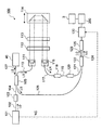
- 1 is a schematic diagram illustrating an example of a configuration of an ophthalmologic imaging apparatus according to an exemplary embodiment.
- 1 is a schematic diagram illustrating an example of a configuration of an ophthalmologic imaging apparatus according to an exemplary embodiment.
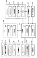
- 1 is a schematic diagram illustrating an example of a configuration of an ophthalmologic imaging apparatus according to an exemplary embodiment.
- 1 is a schematic diagram illustrating an example of a configuration of an ophthalmologic imaging apparatus according to an exemplary embodiment. It is a schematic diagram for explaining an example of processing which an ophthalmologic imaging device concerning an exemplary embodiment performs. It is a schematic diagram for explaining an example of processing which an ophthalmologic imaging device concerning an exemplary embodiment performs.
- the ophthalmologic imaging apparatus can measure the fundus of a living eye using Fourier domain OCT (for example, swept source OCT).
- OCT for example, swept source OCT
- the type of OCT applicable to the embodiment is not limited to the swept source OCT, and may be, for example, a spectral domain OCT or a time domain OCT.
- the application target of the OCT is not limited to the fundus, and may be any part of the eye such as the anterior segment or the vitreous body.
- Example embodiments may be able to process images acquired by modalities other than OCT.
- exemplary embodiments may be capable of processing images acquired by any of a fundus camera, SLO, slit lamp microscope, and ophthalmic surgical microscope.
- An ophthalmologic imaging apparatus may include any of a fundus camera, an SLO, a slit lamp microscope, and a microscope for ophthalmic surgery.
- the image of the subject's eye that can be processed according to the exemplary embodiment may include an image obtained by analyzing an image obtained by any modality.
- analysis images are obtained by analyzing a pseudo-colored image (eg, a segmented pseudo-color image), an image consisting only of a part of the original image (eg, a segment image), and an OCT image.
- a pseudo-colored image eg, a segmented pseudo-color image
- an image consisting only of a part of the original image eg, a segment image
- OCT image OCT image.
- the ophthalmologic imaging apparatus 1 includes a fundus camera unit 2, an OCT unit 100, and an arithmetic and control unit 200.
- the retinal camera unit 2 is provided with an optical system and a mechanism for acquiring a front image of the subject's eye.
- the OCT unit 100 is provided with a part of an optical system and a mechanism for performing the OCT. Another part of the optical system and the mechanism for performing the OCT is provided in the fundus camera unit 2.
- the arithmetic and control unit 200 includes one or more processors that execute various calculations and controls.
- arbitrary elements such as a member for supporting the face of the subject (chin rest, forehead support, etc.) and a lens unit for switching an OCT target site (for example, an anterior segment OCT attachment) And a unit may be provided in the ophthalmologic photographing apparatus 1.
- a “processor” is, for example, a CPU (Central Processing Unit), a GPU (Graphics Processing Unit), an ASIC (Application Specialized Integrated Circuit), a programmable logic device (for example, SPLD (SimpleChip) It means a circuit such as Programmable Logic Device or FPGA (Field Programmable Gate Array).
- the processor realizes the functions according to the embodiment by, for example, reading and executing a program stored in a storage circuit or a storage device.
- the retinal camera unit 2 is provided with an optical system for photographing the fundus oculi Ef of the eye E.
- the acquired image of the fundus oculi Ef (referred to as a fundus image, a fundus photograph, or the like) is a front image such as an observation image or a photographed image.
- the observation image is obtained, for example, by moving image shooting using near-infrared light, and is used for alignment, focusing, tracking, and the like.
- the captured image is, for example, a still image using flash light in a visible region or an infrared region.
- the fundus camera unit 2 includes an illumination optical system 10 and a photographing optical system 30.
- the illumination optical system 10 irradiates the eye E with illumination light.
- the imaging optical system 30 detects the return light of the illumination light from the eye E to be inspected.
- the measurement light from the OCT unit 100 is guided to the eye E through an optical path in the fundus camera unit 2, and the return light is guided to the OCT unit 100 through the same optical path.
- the light (observation illumination light) output from the observation light source 11 of the illumination optical system 10 is reflected by the concave mirror 12, passes through the condenser lens 13, passes through the visible cut filter 14, and becomes near-infrared light. Further, the observation illumination light once converges near the imaging light source 15, is reflected by the mirror 16, and passes through the relay lens system 17, the relay lens 18, the diaphragm 19, and the relay lens system 20. Then, the observation illumination light is reflected at the periphery of the perforated mirror 21 (the area around the perforated portion), passes through the dichroic mirror 46, is refracted by the objective lens 22, and illuminates the eye E (fundus Ef). I do.
- the return light of the observation illumination light from the subject's eye E is refracted by the objective lens 22, passes through the dichroic mirror 46, passes through the hole formed in the central region of the perforated mirror 21, and passes through the dichroic mirror 55.
- the light is reflected by a mirror 32 via a focusing lens 31. Further, this return light passes through the half mirror 33A, is reflected by the dichroic mirror 33, and is imaged on the light receiving surface of the image sensor 35 by the imaging lens 34.
- the image sensor 35 detects return light at a predetermined frame rate.
- the focus (focal position) of the imaging optical system 30 is adjusted so as to match the fundus oculi Ef or the anterior segment.
- the light (photographing illumination light) output from the photographing light source 15 is applied to the fundus oculi Ef through the same path as the observation illumination light.
- the return light of the imaging illumination light from the eye E is guided to the dichroic mirror 33 through the same path as the return light of the observation illumination light, passes through the dichroic mirror 33, is reflected by the mirror 36, and is reflected by the imaging lens 37.
- An image is formed on the light receiving surface of the image sensor 38.
- the liquid crystal display (LCD) 39 displays a fixation target (fixation target image).
- a part of the light beam output from the LCD 39 is reflected by the half mirror 33A, reflected by the mirror 32, passes through the imaging focusing lens 31 and the dichroic mirror 55, and passes through the hole of the perforated mirror 21.
- the light beam that has passed through the hole of the perforated mirror 21 passes through the dichroic mirror 46, is refracted by the objective lens 22, and is projected on the fundus Ef.
- the fixation position of the eye E to be inspected by the fixation target can be changed.
- a fixation position for acquiring an image centered on the macula
- a fixation position for acquiring an image centered on the optic disc a position between the macula and the optic disc.
- a graphical user interface (GUI) for specifying at least one of such typical fixation positions can be provided.
- a GUI or the like for manually moving the fixation position (the display position of the fixation target) can be provided.
- the configuration for presenting the fixation target capable of changing the fixation position to the subject's eye E is not limited to a display device such as an LCD.
- a fixation matrix in which a plurality of light emitting units (light emitting diodes or the like) are arranged in a matrix (array) can be employed instead of a display device.
- the fixation position of the eye E to be inspected by the fixation target can be changed by selectively lighting the plurality of light emitting units.
- one or more movable light emitting units can generate a fixation target whose fixation position can be changed.
- the alignment optical system 50 generates an alignment index used for alignment of the optical system with respect to the eye E to be inspected.
- the alignment light output from the light emitting diode (LED) 51 passes through the stop 52, the stop 53, and the relay lens 54, is reflected by the dichroic mirror 55, passes through the hole of the perforated mirror 21, and passes through the dichroic mirror 46.
- the light is transmitted and projected to the eye E through the objective lens 22.
- Return light (corneal reflected light or the like) of the alignment light from the eye E is guided to the image sensor 35 through the same path as the return light of the observation illumination light.
- Manual alignment or automatic alignment can be performed based on the received light image (alignment index image).
- the alignment index image of the present example is composed of two bright spot images whose positions change depending on the alignment state.
- the two bright spot images are displaced integrally in the xy directions.
- the relative position between the eye E and the optical system changes in the z direction
- the relative position (distance) between the two bright spot images changes.
- the distance between the subject's eye E and the optical system in the z-direction matches the predetermined working distance
- the two bright spot images overlap.
- two bright spot images are presented in or near a predetermined alignment target.
- the two bright spot images overlap and are aligned. Presented in the target.
- the data processing unit 230 detects the positions of the two bright spot images, and the main control unit 211 controls a moving mechanism 150 described below based on the positional relationship between the two bright spot images and the alignment target. .
- the main control unit 211 causes the display unit 241 to display two bright spot images together with the observation image of the eye E, and the user uses the operation unit 242 while referring to the two displayed bright spot images. To operate the moving mechanism 150.
- the focus optical system 60 generates a split index used for focus adjustment for the eye E.
- the focusing optical system 60 is moved along the optical path (illumination optical path) of the illumination optical system 10 in conjunction with the movement of the imaging focusing lens 31 along the optical path (illumination optical path) of the imaging optical system 30.
- the reflection bar 67 is inserted into and removed from the illumination optical path. When performing the focus adjustment, the reflection surface of the reflection bar 67 is arranged obliquely in the illumination optical path.
- Focus light output from the LED 61 passes through a relay lens 62, is split into two light beams by a split indicator plate 63, passes through a two-hole aperture 64, is reflected by a mirror 65, and is reflected by a condensing lens 66 on a reflecting rod 67. Is once imaged on the reflecting surface of and is reflected. Further, the focus light is reflected by the aperture mirror 21 via the relay lens 20, passes through the dichroic mirror 46, and is projected on the eye E through the objective lens 22. The return light of the focus light from the eye E to be inspected (the fundus reflection light or the like) is guided to the image sensor 35 through the same path as the return light of the alignment light. Manual focusing or auto-focusing can be performed based on the received light image (split index image).
- the diopter correction lenses 70 and 71 can be selectively inserted into the photographing optical path between the aperture mirror 21 and the dichroic mirror 55.
- the diopter correction lens 70 is a plus lens (convex lens) for correcting intensity hyperopia.
- the diopter correction lens 71 is a minus lens (concave lens) for correcting strong myopia.
- the dichroic mirror 46 combines the fundus imaging optical path and the OCT optical path (measurement arm).
- the dichroic mirror 46 reflects light in a wavelength band used for OCT and transmits light for fundus imaging.
- the measuring arm is provided with a collimator lens unit 40, a retroreflector 41, a dispersion compensation member 42, an OCT focusing lens 43, an optical scanner 44, and a relay lens 45 in this order from the OCT unit 100 side.
- the retroreflector 41 can be moved in the direction of the arrow shown in FIG. 1, thereby changing the length of the measuring arm.
- the change of the measurement arm length is used for, for example, optical path length correction according to the axial length of the eye, adjustment of the interference state, and the like.
- the dispersion compensating member 42 works together with the dispersion compensating member 113 (described later) disposed on the reference arm to match the dispersion characteristics of the measurement light LS and the reference light LR.
- the OCT focusing lens 43 is moved along the measurement arm to adjust the focus of the measurement arm.
- the movement of the photographing focusing lens 31, the movement of the focusing optical system 60, and the movement of the OCT focusing lens 43 can be controlled in a coordinated manner.
- the optical scanner 44 is disposed substantially at a position optically conjugate with the pupil of the eye E.
- the optical scanner 44 deflects the measurement light LS guided by the measurement arm.
- the optical scanner 44 is a galvano scanner capable of two-dimensional scanning including, for example, a galvanomirror for scanning in the x direction and a galvanomirror for scanning in the y direction.
- the OCT unit 100 is provided with an optical system for applying the swept source OCT.
- This optical system includes an interference optical system.
- This interference optical system divides light from a wavelength-variable light source (wavelength-swept light source) into measurement light and reference light, and superimposes the return light of the measurement light from the eye E and the reference light via the reference optical path. Together, interference light is generated, and this interference light is detected.
- the detection result (detection signal) obtained by the interference optical system is a signal representing the spectrum of the interference light, and is sent to the arithmetic and control unit 200.
- the light source unit 101 includes, for example, a near-infrared tunable laser that changes the wavelength of emitted light at high speed.
- the light L0 output from the light source unit 101 is guided to a polarization controller 103 by an optical fiber 102, and its polarization state is adjusted. Further, the light L0 is guided to the fiber coupler 105 by the optical fiber 104 and split into the measurement light LS and the reference light LR.
- the optical path of the measurement light LS is called a measurement arm or the like, and the optical path of the reference light LR is called a reference arm or the like.
- the reference light LR is guided by the optical fiber 110 to the collimator 111, converted into a parallel light beam, and guided to the retroreflector 114 via the optical path length correction member 112 and the dispersion compensation member 113.
- the optical path length correction member 112 acts to match the optical path length of the reference light LR with the optical path length of the measurement light LS.
- the dispersion compensating member 113 works together with the dispersion compensating member 42 arranged on the measurement arm to match the dispersion characteristics between the reference light LR and the measurement light LS.
- the retro-reflector 114 is movable along the optical path of the reference light LR incident thereon, whereby the length of the reference arm is changed. The change of the reference arm length is used, for example, for correcting the optical path length according to the axial length of the eye and adjusting the interference state.
- the reference light LR that has passed through the Perimeter reflector 114 passes through the dispersion compensating member 113 and the optical path length correcting member 112, is converted from a parallel light beam into a converged light beam by the collimator 116, and is incident on the optical fiber 117.
- the reference light LR that has entered the optical fiber 117 is guided to the polarization controller 118 to adjust its polarization state, is guided to the attenuator 120 through the optical fiber 119, adjusts its light amount, and is transmitted to the fiber coupler 122 through the optical fiber 121. Be guided.
- the measurement light LS generated by the fiber coupler 105 is guided by the optical fiber 127 and converted into a parallel light flux by the collimator lens unit 40, and the retroreflector 41, the dispersion compensating member 42, the OCT focusing lens 43, and the optical scanner 44 Then, the light is reflected by the dichroic mirror 46 via the relay lens 45, refracted by the objective lens 22, and projected to the eye E.
- the measurement light LS is scattered and reflected at various depth positions of the eye E.
- the return light of the measurement light LS from the subject's eye E travels in the same path as the outward path in the opposite direction, is guided to the fiber coupler 105, and reaches the fiber coupler 122 via the optical fiber 128.
- the fiber coupler 122 generates interference light by superimposing the measurement light LS incident via the optical fiber 128 and the reference light LR incident via the optical fiber 121.
- the fiber coupler 122 generates a pair of interference lights LC by splitting the generated interference light at a predetermined split ratio (for example, 1: 1).
- the pair of interference lights LC is guided to the detector 125 through the optical fibers 123 and 124, respectively.
- the detector 125 includes, for example, a balanced photodiode.
- the balanced photodiode has a pair of photodetectors that respectively detect a pair of interference lights LC, and outputs a difference between a pair of detection results obtained by these.
- the detector 125 sends this output (detection signal) to a data acquisition system (DAQ) 130.
- DAQ data acquisition system
- the data acquisition system 130 is supplied with the clock KC from the light source unit 101.
- the clock KC is generated in the light source unit 101 in synchronization with the output timing of each wavelength swept within a predetermined wavelength range by the variable wavelength light source.
- the light source unit 101 for example, splits the light L0 of each output wavelength to generate two split lights, optically delays one of these split lights, synthesizes these split lights, and converts the obtained synthesized light.
- the clock KC is generated based on the detection result.
- the data collection system 130 performs sampling of the detection signal input from the detector 125 based on the clock KC.
- the data collection system 130 sends the result of this sampling to the arithmetic and control unit 200.
- both an element for changing the measurement arm length for example, the retroreflector 41
- an element for changing the reference arm length for example, the retroreflector 114 or the reference mirror
- only one element may be provided.
- the element for changing the difference (optical path length difference) between the measurement arm length and the reference arm length is not limited to these, and may be any element (optical member, mechanism, etc.).
- Control and processing systems> 3 and 4 show configuration examples of a control system and a processing system of the ophthalmologic photographing apparatus 1.
- FIG. The control unit 210, the image construction unit 220, and the data processing unit 230 are provided in the arithmetic and control unit 200, for example.
- the ophthalmologic photographing apparatus 1 may include a communication device for performing data communication with an external device.
- the ophthalmologic photographing apparatus 1 may include a drive device (reader / writer) for performing a process of reading data from a recording medium and a process of writing data to a recording medium.
- Control unit 210 performs various controls.
- Control unit 210 includes a main control unit 211 and a storage unit 212. Further, as shown in FIG. 4, the control unit 210 of the present embodiment includes a scan control unit 213 and a focus control unit 214.
- the main control unit 211 includes a processor and controls each element of the ophthalmologic photographing apparatus 1 (including the elements shown in FIGS. 1 to 4).
- the main control unit 211 is realized by cooperation between hardware including a processor and control software.
- the main control unit 211 can operate the scan control unit 213 and the focus control unit 214 in cooperation (synchronously). Thus, the OCT scan and the focus adjustment are performed cooperatively (synchronously).
- the imaging / focusing drive unit 31A moves the imaging / focusing lens 31 arranged in the imaging optical path and the focus optical system 60 arranged in the illumination optical path.
- the retro-reflector (RR) drive unit 41A moves the retro-reflector 41 provided on the measurement arm under the control of the main control unit 211.
- the OCT focusing drive unit 43A moves the OCT focusing lens 43 arranged on the measurement arm under the control of the main control unit 211.
- the optical scanner 44 provided on the measurement arm operates under the control of the main control unit 211.
- the retro-reflector (RR) driving unit 114A moves the retro-reflector 114 disposed on the reference arm under the control of the main control unit 211.
- Each of the above-described driving units includes an actuator such as a pulse motor that operates under the control of the main control unit 211.
- the moving mechanism 150 moves at least the fundus camera unit 2 three-dimensionally, for example.
- the moving mechanism 150 includes an x stage movable in the ⁇ x direction (lateral direction), an x moving mechanism that moves the x stage, and a y stage movable in the ⁇ y direction (vertical direction).
- Each of these moving mechanisms includes an actuator such as a pulse motor that operates under the control of the main control unit 211.
- the storage unit 212 stores various data.
- the data stored in the storage unit 212 includes an OCT image, a fundus image, eye information to be examined, control parameters, and the like.
- Examinee eye information includes examinee information such as patient ID and name, identification information of left / right eyes, electronic medical record information, and the like.
- the control parameters include, for example, parameters (scan control parameters) used for OCT scan control and parameters (focus control parameters) used for focus (focal position) control.
- the scan control parameter is a parameter indicating the content of control on the optical scanner 44.
- Examples of the scan control parameters include a parameter indicating a scan pattern, a parameter indicating a scan speed, and a parameter indicating a scan interval.
- the scan speed is defined as, for example, the repetition rate of A-scan.
- the scan interval is defined as, for example, an interval between adjacent A scans, that is, an arrangement interval of scan points. The scan pattern will be described later.
- the focus control parameter is a parameter indicating the content of the control for the OCT focus driving unit 43A.
- the focus control parameters include a parameter indicating the focal position of the measurement arm, a parameter indicating the moving speed of the focal position, a parameter indicating the moving acceleration of the focal position, and the like.
- the parameter indicating the focal position is, for example, a parameter indicating the position of the OCT focusing lens 43.
- the parameter indicating the moving speed of the focal position is, for example, a parameter indicating the moving speed of the OCT focusing lens 43.
- the parameter indicating the moving acceleration of the focal position is, for example, a parameter indicating the moving acceleration of the OCT focusing lens 43.
- the moving speed may or may not be constant. The same applies to the movement acceleration.
- the scan control unit 213 controls the optical scanner 44 based on the scan control parameters.
- the scan control unit 213 may further execute control of the light source unit 101. Details of the processing executed by the scan control unit 213 will be described later.
- the scan control unit 213 is included in the main control unit 211.
- the scan control unit 213 is realized by cooperation between hardware including a processor and scan control software.
- the focus control unit 214 controls the OCT focus driving unit 43A based on the focus control parameters. Details of the processing executed by the focus control unit 214 will be described later.
- the focus control unit 214 is included in the main control unit 211.
- the focus control unit 214 is realized by cooperation between hardware including a processor and focus control software.
- the image construction unit 220 includes a processor, and forms OCT image data of the fundus oculi Ef based on a signal (sampling data) input from the data acquisition system 130.
- the OCT image data is, for example, B-scan image data (two-dimensional tomographic image data).
- the processing for forming the OCT image data includes noise removal (noise reduction), filtering, fast Fourier transform (FFT), and the like, similarly to the conventional Fourier domain OCT.
- the image construction unit 220 executes a known process according to the type.
- the image construction unit 220 forms three-dimensional data of the fundus oculi Ef based on the signal input from the data collection system 130.
- the three-dimensional data is three-dimensional image data representing a three-dimensional area (volume) of the fundus oculi Ef.
- the three-dimensional image data means image data in which the positions of pixels are defined by a three-dimensional coordinate system. Examples of three-dimensional image data include stack data and volume data.
- the stack data is image data obtained by three-dimensionally arranging a plurality of tomographic images obtained along a plurality of scan lines based on a positional relationship between the scan lines. That is, the stack data is an image obtained by expressing a plurality of tomographic images originally defined by individual two-dimensional coordinate systems in one three-dimensional coordinate system (that is, embedding them in one three-dimensional space). Data. Alternatively, the stack data is obtained by three-dimensionally arranging a plurality of A-scan data obtained for each of a plurality of two-dimensionally arranged scan points (scan point arrays) based on the positional relationship between these scan points. Image data.
- Volume data is image data in which voxels arranged three-dimensionally are pixels, and is also called voxel data.
- the volume data is formed by applying interpolation processing, voxelization processing, or the like to stack data.
- the image construction unit 220 renders the three-dimensional image data to form a display image.
- Examples of applicable rendering methods include volume rendering, surface rendering, maximum intensity projection (MIP), minimum intensity projection (MinIP), and multi-section reconstruction (MPR).
- the image construction unit 220 can form an OCT front image (OCT en-face image) based on three-dimensional image data. For example, the image construction unit 220 can construct projection data by projecting the three-dimensional image data in the z direction (A line direction, depth direction). Further, the image construction unit 220 can construct a shadowgram by projecting a part of the three-dimensional image data in the z direction.
- OCT front image OCT en-face image
- the partial three-dimensional image data projected to construct a shadowgram is set using, for example, segmentation.
- the segmentation is a process for specifying a partial area in an image.
- the segmentation is used to specify an image region corresponding to a predetermined tissue of the fundus oculi Ef.
- the segmentation is performed by, for example, the image construction unit 220 or the data processing unit 230.
- the ophthalmologic imaging apparatus 1 may be capable of performing OCT-angiography.
- OCT angiography is an imaging technique for constructing an image in which retinal blood vessels and choroidal blood vessels are emphasized (for example, see Japanese Patent Application Laid-Open No. 2015-515894).
- the fundus tissue (structure) does not change with time, but the blood flow portion inside the blood vessel changes with time.
- OCT angiography an image is generated by emphasizing a portion (blood flow signal) where such a temporal change exists.
- OCT angiography is also called OCT motion contrast imaging (motion @ contrast @ imaging). Images acquired by OCT angiography are called angiographic images, angiograms, motion contrast images, and the like.
- the ophthalmologic imaging apparatus 1 When OCT angiography is performed, the ophthalmologic imaging apparatus 1 repeatedly scans the same area of the fundus oculi Ef a predetermined number of times. For example, scanning can be repeatedly performed along a locus between two points on a predetermined scan pattern (for example, a spiral scan pattern).
- the image builder 220 can build a motion contrast image from the data set collected by the data collection system 130 in the repetitive scan.
- This motion contrast image is an angiographic image in which the temporal change of the interference signal caused by the blood flow in the fundus oculi Ef is emphasized and imaged.
- OCT angiography is applied to a three-dimensional region of the fundus oculi Ef, and an image representing a three-dimensional distribution of blood vessels of the fundus oculi Ef is obtained.
- the image constructing unit 220 can construct any two-dimensional angiographic image data and / or any pseudo three-dimensional angiographic image data from the three-dimensional angiographic image data. It is.
- the image construction unit 220 can construct two-dimensional angiographic image data representing an arbitrary cross section of the fundus oculi Ef by applying multi-sectional reconstruction to the three-dimensional angiographic image data.
- the image construction unit 220 is realized by cooperation between hardware including a processor and image construction software.
- the data processing unit 230 includes a processor and applies various types of data processing to the image of the eye E.
- the data processing unit 230 is realized by cooperation between hardware including a processor and data processing software.
- the data processing unit 230 can perform registration (registration) between two images acquired for the fundus oculi Ef.
- the data processing unit 230 can perform registration between the three-dimensional image data acquired by OCT and the front image acquired by the fundus camera unit 2.
- the data processing unit 230 can perform registration between two OCT images acquired by OCT.
- the data processing unit 230 can perform registration between the two front images acquired by the fundus camera unit 2.
- registration can be applied to the analysis result of the OCT image or the analysis result of the front image.
- the registration can be performed by a known method, and includes, for example, feature point extraction and affine transformation.
- the data processing unit 230 of the present embodiment includes a parameter setting unit 231 and a movement detection unit 232.
- the parameter setting unit 231 sets a focus control parameter based on the OCT image of the fundus oculi Ef acquired in advance.
- This OCT image preliminary image
- a focus control parameter is set based on the detected shape.
- the ophthalmologic photographing apparatus 1 can acquire an OCT image used for setting a focus control parameter. For example, the ophthalmologic imaging apparatus 1 can apply a preliminary OCT scan to the eye E before applying the wide-angle OCT scan to the eye E.
- the preparatory OCT scan is performed so as to pass through both the central region and the peripheral region of the wide-angle OCT scan application area.
- the macula area (and its surrounding area) is set as the central area of the fundus oculi Ef, and an area at least a predetermined distance from the macula is set as the peripheral area.
- a preliminary OCT scan for a wide-angle OCT scan of the anterior segment a vertex of the cornea and a region near the vertex are set as the central region of the anterior segment, and a region that is at least a predetermined distance from the vertex of the cornea is a peripheral region.
- the pattern of the preparatory OCT scan may be a scan pattern including a large number of scan points such as a three-dimensional scan (raster scan), but the purpose of the preparatory OCT scan is to define a rough shape of the wide-angle OCT scan application area.
- a relatively simple scan pattern such as B scan (line scan), cross scan, and radial scan is sufficient.
- the image construction unit 220 constructs a preliminary image from data collected by the preliminary OCT scan.
- the preliminary images typically include one or more B-scan images representing one or more cross-sections of the central region and one or more cross-sections of the peripheral region of the wide-angle OCT scan application area.
- the outer edge of the central region and the outer edge and the inner edge of the peripheral region are all circular, but the shapes of the central region and the peripheral region are not limited thereto.
- either the outer edge of the central area and the outer edge or the inner edge of the peripheral area may be rectangular, and may have any shape.
- the outer edge shape and the inner edge shape of the peripheral edge region may be the same or may be different from each other.
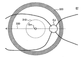
- An example of the preliminary OCT scan shown in FIG. 5A is one B scan 330 that passes through a central region 310 including the macula Em of the fundus oculi Ef and a peripheral region 320 (region indicated by oblique lines) away from the macula Em. .
- Symbol Ed indicates the optic disc.
- one B-scan image representing the section to which the B-scan 330 has been applied is obtained.
- the B-scan image of the present example shows a relative relationship between the depth position (z position) of the central region 310 and the depth position of the peripheral region 320. In this example, a relative depth positional relationship between the center region 310 and the peripheral region 320 is obtained only in the direction in which the B scan 330 is applied.
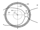
- the example of the preparatory OCT scan shown in FIG. 5B is two B scans 341 and 342 each passing through the central region 310 and the peripheral region 320.
- the two B scans 341 and 342 are orthogonal to each other. That is, the preparatory OCT scan of this example is a cross scan.
- a B-scan image representing a section to which the B-scan 341 has been applied and a B-scan image representing a section to which the B-scan 342 has been applied are obtained.
- Each of the two B-scan images of the present example represents a relative relationship between the depth position (z position) of the central region 310 and the depth position of the peripheral region 320.
- the relative depth position relationship between the center region 310 and the peripheral region 320 in the direction in which the B-scan 341 is applied and the direction in which the B-scan 342 is applied, that is, in two directions orthogonal to each other. can get.
- a radial scan (a plurality of B scans arranged at equal angular intervals) is applied as a preparatory OCT scan
- the center region and the peripheral region are arranged in a plurality of directions arranged at equal angular intervals from each other. Is obtained.
- a three-dimensional scan for example, a raster scan
- the relative depth position between the center region and the peripheral region in any direction on the xy plane A relationship is obtained.
- a relative depth position relationship between the center region and the peripheral region can be obtained in one or more directions according to the scan pattern.
- the pattern of the preparatory OCT scan thus determines the content (direction, etc.) and amount (angle interval, etc.) of the information acquired as the relative depth position relationship. Conversely, the pattern of the preparatory OCT scan can be determined according to the content and amount of information desired to be acquired as the relative depth position relationship.
- the determination of the preliminary OCT scan pattern is performed, for example, in advance or for each inspection.
- the parameter setting unit 231 sets one or more focus control parameters based on the preliminary image.
- the focus control parameter is a parameter indicating the content of control for the OCT focus driving unit 43A, and examples thereof include a parameter indicating the focus position of the measurement arm, a parameter indicating the moving speed of the focus position, and a focus position.
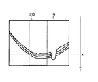
- the preliminary image G is, for example, an image constructed from data collected by the B scan 330 illustrated in FIG. 5A (or the B scan 341 illustrated in FIG. 5B or a similar B scan).
- An area having a contour indicated by a dotted line denoted by reference numeral 310 corresponds to an intersection area (common area) between the central area 310 and the B-scan 330 shown in FIG. 5A.
- the region indicated by oblique lines with the reference numeral 320 corresponds to the intersection region (common region) between the peripheral region 320 and the B scan 330 shown in FIG. 5A.
- the preparatory image G has two peripheral regions 320.
- the symbol Em is an image region of the macula
- the symbol Ed is an image region of the optic disc.
- the parameter setting unit 231 analyzes the central region 310 of the preliminary image G, detects the macula region Em, and specifies its depth position (z coordinate). For this purpose, the parameter setting unit 231 performs, for example, segmentation for specifying the image region of the inner limiting membrane (ILM), shape analysis for detecting the macula region Em from the specified shape (dent) of the inner limiting membrane region, and detection. Calculating the z-coordinate of the pixel at the representative point of the obtained macular region Em.
- the representative point of the macula region Em may be, for example, the center of the macula (fovea, the deepest part of the dent).
- the z coordinate of the macula center obtained by this example and z 1 (see FIG. 6B). Note that the part where the z coordinate is specified is not limited to the center of the macula, and may be any representative point in the central region 310.
- the parameter setting unit 231 analyzes the peripheral region 320 of the preliminary image G, detects an image region of a predetermined tissue (for example, an inner limiting membrane), and specifies a depth position (z coordinate) thereof.
- the parameter setting unit 231 includes, for example, a segmentation for specifying an image region of a predetermined tissue, and a process for obtaining az coordinate of a pixel at a representative point of the specified image region.
- the representative point of the image region of the predetermined tissue may be, for example, the center position of the peripheral region 320 in the B-scan direction or the end point of the peripheral region 320.
- the z-coordinate of the boundary layer among the respective center positions of the two peripheral regions 320 of the preparatory image G is obtained by the present example in the case of the representative point and z 21 and z 22 (see FIG. 6C).
- the parameter setting unit 231 sets a focus control parameter based on the z coordinate (z 1 ) of the representative point of the central area 310 and the z coordinate (z 21 , z 22 ) of the representative point of the peripheral area 320. .
- the parameter setting unit 231 determines the position of the OCT focusing lens 43 corresponding to the z coordinate (z 1 ) of the representative point of the central area 310 and the z coordinate (z 21 and z 22 of the representative point of the peripheral area 320, respectively). ), The position of the OCT focusing lens 43 can be obtained.
- the position of the OCT focusing lens 43 corresponds to the focal position of the measurement arm. This example can be said to be a process for obtaining the absolute position of the OCT focusing lens 43.
- the processing of this example includes, for example, a coherence gate position (arm length, position of the retroreflector 41, position of the retroreflector 114) when the preliminary image G is acquired, and a scale of the z axis (for example, per pixel). Distance).
- the parameter setting unit 231 determines the position (focal position) of the OCT focusing lens 43 corresponding to the z coordinate (z 1 ) of the representative point of the central area 310 and the z coordinate (z 21 and z 22 ) of the representative point of the peripheral area 320.
- the OCT focusing lens 43 (focal position) corresponding to i.
- this example can be said to be a process for obtaining the relative position of the OCT focusing lens 43.
- the processing of this example is executed based on, for example, the scale of the z-axis.
- the parameter setting unit 231 determines the position (focal position) of the OCT focusing lens 43 corresponding to the z coordinate (z 1 ) of the representative point of the central area 310 and the z coordinate (z 21 and z 22 ) of the representative point of the peripheral area 320. ),
- the focus position change range including the position (focus position) of the OCT focusing lens 43 corresponding to (i).
- the focus position change range is a range of the focus position changed by the focus control, and is defined as a moving range of the OCT focusing lens 43, for example.
- the processing of this example is executed based on, for example, the coherence gate position when the preliminary image G is acquired and the scale of the z-axis.
- the parameter setting unit 231 can set the speed at which the focus position of the measurement arm moves.
- the processing of this example is executed based on, for example, the absolute position or relative position of the OCT focusing lens 43 described above, or based on the moving range of the OCT focusing lens 43.
- the parameter setting unit 231 can set the acceleration for moving the focal position of the measurement arm.
- the processing of this example is based on, for example, the absolute position or relative position of the OCT focusing lens 43, based on the moving range of the OCT focusing lens 43, or based on the moving speed of the OCT focusing lens 43. Will be executed.
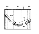
- the focal position moves in the + z direction from the left peripheral region 320 side toward the central region 310 side, and the focal position moves rightward from the central region 310 side.
- the parameter setting unit 231 sets the focus control parameter so that the focal position moves in the ⁇ z direction as going toward the peripheral region 320 side of.
- the parameter setting unit 231 can set information indicating a relationship between a scan control parameter and a focus control parameter based on, for example, any of the above-described examples of the focus control parameter.
- a scan pattern for a wide-angle OCT scan is set.
- the wide-angle OCT scan pattern is set, for example, in advance or for each inspection.
- the wide-angle OCT scan pattern includes a scan pattern including a continuous first partial pattern for the central region of the wide-angle OCT scan application area and a continuous second partial pattern for the peripheral region.
- the first partial pattern is a pattern for continuously scanning at least a part of the central area
- the second partial pattern is a pattern for continuously scanning at least a part of the peripheral area.
- continuous scan means, for example, sequentially scanning a plurality of scan points arranged in a predetermined pattern in accordance with the arrangement order.
- the wide-angle OCT scan pattern may include a curved scan pattern defined by a polar coordinate system having the origin at the center of the wide-angle OCT scan application area.
- the center of the wide-angle OCT scan application area may be, for example, the center of the macula or another part of the fundus. As described above, the center of the wide-angle OCT scan application area may be defined based on the site or tissue of the eye to be inspected, but may be defined based on the ophthalmologic imaging apparatus 1.
- the center of the wide-angle OCT scan application area may be defined as a neutral position (neutral direction) of a variable direction mirror (such as a galvanometer mirror) of the optical scanner 44, or may be defined as an optical axis of the measurement arm (optical axis of the objective lens 22). ) May be defined.
- Examples of curved wide-angle OCT scan patterns defined in a polar coordinate system having the origin at the center of the wide-angle OCT scan application area include a spiral pattern and a concentric pattern.
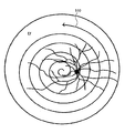
- the wide-angle OCT scan pattern is a spiral scan pattern from the center of the wide-angle OCT scan application area to the outer edge (see the spiral scan pattern 510 shown in FIG. 8A).
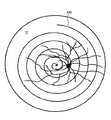
- a spiral scan pattern (see spiral scan pattern 520 shown in FIG. 8B) from the outer edge of the wide-angle OCT scan application area toward the center may be used.
- the spiral scan pattern 510 shown in FIG. 8A has the center of the macula in the central region (not shown) as the scan start point, and passes through the peripheral region (not shown) while increasing the radial radius as the declination changes.
- the scan ends at the outer edge (near).
- the spiral scan pattern 520 shown in FIG. 8B has an outer edge (near) as a scan start point, passes through a peripheral area (not shown) while decreasing a radial radius with a change in declination, and a central area (not shown). To the scan end point set at the center of the macula.
- the spiral interval is drawn coarser than the actual one for the purpose of illustration.
- the intervals between the spirals may be so close that three-dimensional image data can be constructed.
- focus control parameters that can be set by the parameter setting unit 231 when the wide-angle OCT scan pattern is the above-described curved scan pattern (for example, a spiral scan pattern) will be described with reference to FIGS. 9A to 9D. .
- the focus control parameters that can be set by the parameter setting unit 231 are not limited to these examples, and may be any focus control parameters that satisfy the conditions required in the present embodiment.
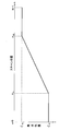
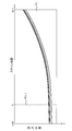
- the horizontal axis of the coordinate system indicates the scan position
- the vertical axis indicates the focus position.
- the focal position on the vertical axis is defined as az coordinate.
- the focus control parameter of FIG. 9A is applicable when a spiral scan pattern from the center of the wide-angle OCT scan application area to the outer edge is employed, for example, like a spiral scan pattern 510 shown in FIG. 8A.
- a description will be given together with the spiral scan pattern 510.
- zeta 11 is either set equal to z 1, or zeta 11 is set substantially equal to z 1.
- zeta 12 is set equal to z 21
- zeta 12 is either set to a value approximately equal to z 21
- zeta 12 is set equal to z 22
- zeta 12 is approximately equal to z 22 either set to, or, zeta 12 is set to a value obtained from both z 21 and z 22.
- the focus control parameters shown in FIG. 9A include coordinates (0, 11 11 ) corresponding to the scan start point and coordinates (N ⁇ 1, 12 12 ) corresponding to the scan end point in the two-dimensional coordinate system (n, z). It can be set as a connected smooth curve (for example, spline curve, Bezier curve).
- the two-dimensional coordinate system (n, z) in the example shown in FIG. 9B is the same as that in the example shown in FIG. 9A.
- the focus control parameter of FIG. 9B can be applied when a spiral scan pattern from the outer edge to the center of the wide-angle OCT scan application area is adopted, for example, like a spiral scan pattern 520 shown in FIG. 8B.
- the example will be described together with the spiral scan pattern 520.
- the focus control parameters shown in FIG. 9B include coordinates (0, 21 21 ) corresponding to the scan start point and coordinates (N ⁇ 1, 22 22 ) corresponding to the scan end point in the two-dimensional coordinate system (n, z). It can be set as a connected smooth curve (for example, spline curve, Bezier curve).
- the two-dimensional coordinate system (n, z) in the example shown in FIG. 9C is the same as that in the example shown in FIG. 9A.
- the focus control parameter of FIG. 9C is applicable when a spiral scan pattern from the center of the wide-angle OCT scan application area to the outer edge is employed, for example, like a spiral scan pattern 510 shown in FIG. 8A.
- a description will be given together with the spiral scan pattern 510.
- the focal position ⁇ 32 is obtained by, for example, any statistical processing.
- the step-like focus control parameter shown in FIG. 9C can be inverted.
- the focus control parameter obtained by the inversion can be applied when a spiral scan pattern from the outer edge to the center of the wide-angle OCT scan application area is adopted, for example, like a spiral scan pattern 520 shown in FIG. 8B.
- a smooth curve for example, a spline curve or a Bezier curve
- a smooth curve for example, a spline curve, Bezier
- connecting the coordinates (n 32 , ⁇ 32 ) and the coordinates (N-1, ⁇ 33 ) to the scan position section n [n 32 , N ⁇ 1].
- the focus control parameter partially replaced with a curve is used as the focus control parameter. It is possible to invert.
- the two-dimensional coordinate system (n, z) in the example shown in FIG. 9D is the same as that in the example shown in FIG. 9A.
- the focus control parameter of FIG. 9D is applicable when a spiral scan pattern from the center of the wide-angle OCT scan application area to the outer edge is employed, for example, like a spiral scan pattern 510 shown in FIG. 8A.
- a description will be given together with the spiral scan pattern 510.
- the focus control parameter shown in FIG. 9D can be inverted.
- the focus control parameter obtained by the inversion can be applied when a spiral scan pattern from the outer edge to the center of the wide-angle OCT scan application area is adopted, for example, like a spiral scan pattern 520 shown in FIG. 8B.
- Curve for example, spline curve, Bezier curve
- the focus control parameter partially replaced with a curve is used as the focus control parameter. It is possible to invert.
- the depth position (z coordinate) of one representative point (the macula center) in the central region 310 is obtained, and this is used as the depth position of the central region 310.
- statistical processing can be applied to two or more depth positions to determine the depth position of the central region.
- the statistical value obtained from two or more depth positions may be, for example, any one of an average value, a weighted average value, an intermediate value, a mode value, a maximum value, and a minimum value. Similar processing can be applied to the case where the depth position of the peripheral area is obtained.
- Information representing a change in the depth position in the central region can be obtained. For example, based on these depth positions, a graph (focus control parameter) representing a curve, linear, or stepwise change in the depth position in the central region can be obtained.
- 9A and 9B are examples of a curve-like change. Although illustration is omitted, as an example of a linear change in the depth position in the central region, the coordinates (0, 31 31 ) and the coordinates (n 31 , 32 32 ) are connected in the two-dimensional coordinate system shown in FIG. 9C.
- the process of setting the focus control parameter by obtaining two or more depth positions in the center region is performed, for example, when the width of the center region (the length in the direction orthogonal to the z direction) is relatively large. It is considered effective when the change in the depth position in the central region is large (for example, when the difference between the maximum depth position and the minimum depth position in the central region is large).
- the parameter setting unit 231 may determine the number of points in the central region for which the depth region is determined according to the width of the central region and / or the magnitude of the change in the depth position in the central region. (And position). Similar processing can be applied to the case where the focus control parameter of the peripheral area is obtained.
- the central region (310) and the peripheral region (320) are separated from each other.
- an annular (annulus) -shaped intermediate region exists between the outer edge of the central region and the inner edge of the peripheral region.
- the outer edge of the central area may coincide with the inner edge of the peripheral area.
- the central region and the peripheral region can be arbitrarily defined.
- the central region and the peripheral region may be defined according to the site of the fundus.
- an area centered on a predetermined part of the fundus (for example, the center of the macula) and within a predetermined first distance from the center can be set as the central area.
- an area that is equal to or longer than a predetermined second distance (which is equal to or longer than the first distance) from the center can be set as the peripheral area.
- the third distance representing the outer edge of the peripheral area may be further set, or the outer edge of the wide-angle OCT scan application area may be set as the outer edge of the peripheral area.
- the distance in this example may be a distance at the fundus, a distance calculated optically, or a standard distance obtained from a model eye or clinical data.
- center region and the peripheral region is a definition corresponding to the OCT scan.
- a first area including the center of the wide-angle OCT scan application area is set as a central area, and a second area located outside the first area is set as a peripheral area.
- a scan pattern composed of a curve such as a spiral scan pattern
- a scan pattern composed of at least a part of a straight line may be employed.
- a spiral scan pattern composed of a plurality of straight lines can be applied.
- the setting of the wide-angle OCT scan pattern and the focus control parameter (and the scan speed) exemplified above includes the setting of the moving speed and / or the moving acceleration of the focal position.
- the slope of the graph indicating the focus control parameter corresponds to the moving speed
- the rate of change of the slope of the graph corresponds to the moving acceleration.
- the focus position (first focus position) applied to the center area is + z side of the focus position (second focus position) applied to the peripheral area.
- the focal length (first focal length) corresponding to the first focal position is set longer than the focal length (second focal length) corresponding to the second focal position. This depends on the shape of the eye to be examined (fundus). However, the first focal length need not be longer than the second focal length.
- the parameter setting unit 231 that can execute the above-described processing is realized by cooperation between hardware including a processor and parameter setting software.
- the ophthalmologic photographing apparatus 1 includes a fundus camera unit 2 that repeatedly photographs the eye E and acquires a time-series image.
- the time-series image acquired by the fundus camera unit 2 is, for example, the above-described observation image.
- the movement detection unit 232 analyzes the observation image acquired by the fundus camera unit 2 and detects the movement of the eye E. For example, the movement detection unit 232 analyzes each image included in the observation image, detects a feature point, and obtains a time-series change in the position of the feature point.
- the feature points may be, for example, the center, center of gravity, and contour of the pupil, and the center, center of gravity, and contour of the iris.
- the scan controller 213 can control the optical scanner 44 based on the output from the movement detector 213 while controlling the optical scanner 44 and the OCT unit 100 according to the wide-angle OCT scan pattern.
- the control of the optical scanner 44 based on the output from the movement detection unit 213 is so-called tracking control.
- Tracking is executed by the following series of processes disclosed in, for example, JP-A-2017-153543.
- the movement detection unit 232 registers any frame (front image) of the observation image acquired by the fundus camera unit 2 as a reference image.
- the movement detection unit 232 obtains a change in the position of the feature point in another frame with respect to the position of the feature point in the reference image. This corresponds to obtaining a time-series change in the position of the feature point, that is, obtaining a displacement between the reference image and another frame. Note that, when the displacement exceeds a threshold value due to blinking or fixation deviation or when the displacement cannot be detected, the movement detection unit 232 can register a frame acquired thereafter as a new reference image. . Further, the method for obtaining the time-series change of the position of the feature point is not limited to this. For example, the displacement of the feature point between two consecutive frames may be sequentially obtained.
- the movement detecting unit 232 sends control information for canceling the time-series change to the scan control unit 213 every time a time-series change in the position of the feature point is obtained.
- the scan control unit 213 corrects the direction of the optical scanner 44 based on the sequentially input control information.
- the movement detection unit 232 is realized by cooperation between hardware including a processor and movement detection software.
- the user interface 240 includes a display unit 241 and an operation unit 242.
- the display unit 241 includes the display device 3.
- the operation unit 242 includes various operation devices and input devices.
- the user interface 240 may include a device in which a display function and an operation function are integrated, such as a touch panel, for example. Embodiments that do not include at least a portion of the user interface 240 can also be constructed.
- the display device may be an external device connected to the ophthalmic imaging apparatus.
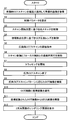
- the ophthalmologic imaging apparatus 1 applies a preliminary OCT scan to the fundus oculi Ef using the optical scanner 44 and the OCT unit 100.
- the image construction unit 220 constructs a preliminary image from data collected by the preliminary OCT scan.
- the preparatory image is sent to the parameter setting unit 231.
- the parameter setting unit 231 sets a focus control parameter based on the preliminary image obtained in step S1.
- the set control parameters are stored in the storage unit 212, for example.
- the ophthalmologic imaging apparatus 1 may set a wide-angle OCT scan application area, a center area, a peripheral area, a scan control parameter, and the like. Any one of these conditions may be a fixed condition, a condition selected from a plurality of options, or a condition manually set by a user.
- the parameter setting unit 231 may set the focus control parameters based on the result of these settings and the preliminary image.
- the central area 310 and the peripheral area 320 shown in FIG. 5A, the spiral scan pattern 510 shown in FIG. 8A, and the focus control parameters shown in FIG. 9A are applied. It is also assumed that the outer edge of the peripheral area 320 defines the outer edge of the wide-angle OCT scan application area.
- the scan control unit 213 specifies a scan start position based on the scan control parameters set in step S2 or earlier, and controls the optical scanner 44 based on the scan start position. Thereby, each galvanomirror included in the optical scanner 44 is arranged in a direction corresponding to the scan start position.
- a fixation target corresponding to a fixation position for acquiring an image centered on the macula is displayed on the LCD 39, and the center of the wide-angle OCT scan application area is set to the center of the macula.
- the macula center is arranged on the optical axis of the measurement arm. Therefore, in this example, each galvanomirror of the optical scanner 44 is arranged at the neutral position.
- the focus control unit 214 specifies an initial focus position in the focus control based on the focus control parameters set in step S2, controls the OCT focus driving unit 43A based on the initial focus position, and controls the OCT focus lens 43. Move.
- the control of the OCT focus driving unit 43A is executed.
- control according to step S4 may be performed before the control according to step S3. Further, the control according to step S3 and the control according to step S4 may be performed in parallel.
- a wide-angle OCT scan start instruction is input to the scan control unit 213 and the focus control unit 214.
- This instruction may be given manually by the user, or the main control unit 211 receives the instruction that a predetermined condition is satisfied (for example, that the control in step S3 and the control in step S4 are completed). It may be performed automatically.
- step S6 Start cooperative execution of scan control and focus control
- the scan control unit 213 and the focus control unit 214 start control in cooperation with each other, so that the wide-angle OCT scan is started.
- the scan control by the scan control unit 213 and the focus control by the focus control unit 214 are executed based on the focus control parameters (the graph indicating the relationship between the scan position n and the focus position z) shown in FIG. 9A. .
- the optical scanner 44 and the OCT unit 100 are controlled so that the A-scan is applied to.
- the OCT focusing drive unit 43A is controlled so that the OCT focusing lens 43 is disposed.
- step S7 Start tracking
- the projection position of the measurement light LS (the A scan application position) is adjusted in accordance with the movement of the eye E to be inspected.
- the tracking for correcting () is started.
- the tracking is executed by the fundus camera unit 2, the movement detection unit 232, the scan control unit 213, and the like in the manner described above. Accordingly, even when the eye E moves during execution of the wide-angle OCT scan, the spiral scan pattern 510 illustrated in FIG. 8A can be applied.
- step S6 ends when the OCT scan along the spiral scan pattern 510 shown in FIG. 8A is performed, for example.
- the OCT scan along the wide-angle OCT scan pattern is executed one or more predetermined times.
- the OCT scan along the spiral scan pattern 510 can be performed two or more times.
- two or more OCT images are constructed from two or more data sets collected by these two or more OCT scans, and the two or more OCT images are combined (averaged). be able to.
- the image construction unit 220 constructs an OCT image from data collected by the wide-angle OCT scan performed in steps S6 to S8.
- the spiral scan pattern 510 shown in FIG. 8A is typically defined using a two-dimensional polar coordinate system (r, ⁇ ).
- the OCT image constructed in step S9 is also defined using the two-dimensional polar coordinate system (r, ⁇ ). That is, the positions of the plurality of A-scan images constituting the OCT image constructed in step S9 are defined using the two-dimensional polar coordinate system (r, ⁇ ).
- step S9 OCT images H 1 shown in FIG. 11 is constructed.
- the definition formula of the spiral scan pattern is not limited to this example, and the coordinate system defining the wide-angle OCT scan pattern and the OCT image is not limited to the two-dimensional polar coordinate system.
- the image construction unit 220 applies coordinate transformation to the OCT image constructed in step S9.
- the image constructing unit 220 determines the eye E to be inspected according to the curved scan pattern.
- An OCT image defined in a polar coordinate system is formed from the data collected by the OCT scan applied to (S9), and the OCT image is converted into an image defined in a three-dimensional orthogonal coordinate system (S10).
- step S9 OCT images H 1 shown in FIG. 11 is constructed
- the image construction unit 220 a two-dimensional polar coordinate system (r, theta) and two-dimensional orthogonal coordinate system (x, y) coordinate conversion formula between the .
- Each OCT image H 2 (m) is a B-scan image along the x direction, and is defined using a two-dimensional orthogonal coordinate system (x, z). Further, M OCT images H 2 (1) to H 2 (M) are arranged along the y direction. Thus, the M OCT images H 2 (1) to H 2 (M) are defined using the three-dimensional orthogonal coordinate system (x, y, z).
- the image construction unit 220 can construct a three-dimensional image from the OCT image after the coordinate transformation obtained in step S10.
- step S10 for example, M OCT images H 2 (1) to H 2 (M), which are stack data, are obtained.
- the image construction unit 220 can construct volume data by voxelizing the M OCT images H 2 (1) to H 2 (M).
- the image construction unit 220 can render the three-dimensional image constructed in step S11.
- the main control unit 211 can cause the display unit 241 to display the obtained rendering image.
- the ophthalmologic imaging apparatus (1) includes a data collection unit, an image construction unit, a focus position changing unit, a scan control unit, and a focus control unit.
- the data collection unit collects data by applying an OCT scan to the eye to be inspected (E).
- the data collection unit includes the OCT unit 100 and elements (such as the retroreflector 41, the OCT focusing lens 43, the optical scanner 44, and the objective lens 22) in the fundus camera unit 2 that constitute a measurement arm. .
- the image construction unit constructs an image from the data collected by the data collection unit.
- the image construction unit includes the image construction unit 220.
- the focus position changing unit is provided on the optical path (measurement arm) of the measurement light projected to the eye E by the data collection unit, and changes the position of the focus of the measurement arm.
- the focus position changing unit includes the OCT focusing lens 43 and the OCT focusing driving unit 43A.
- the scan control unit includes a scan pattern including a continuous first partial pattern for a central region (310) of the OCT scan application area (wide-angle OCT scan application area) and a continuous second partial pattern for a peripheral region (320).
- the data acquisition unit is controlled according to a wide-angle OCT scan pattern).
- the scan control unit includes the scan control unit 213.
- the focus control unit controls the focus position changing unit to apply the first focus position in parallel with the application of the OCT scan to at least a part of the first partial pattern. Further, the focus control unit controls the focal position changing unit to apply a second focal position different from the first focal position in parallel with the application of the OCT scan to at least a part of the second partial pattern.
- the focus control unit includes the focus control unit 214. Further, in the above example, at least a portion of the first partial pattern corresponds to at least a portion of the central region 310, and the first focal position corresponds to the z-coordinate zeta 11 of FIG. 9A, for example. Further, in the above example, at least part of the second partial pattern corresponds to at least a portion of the peripheral region 320 and the second focal position corresponds to the z-coordinate zeta 12 of FIG. 9A, for example.
- a scan pattern including a continuous first partial pattern for the central region and a continuous second partial pattern for the peripheral region can be applied.
- the central region is located at a relatively deep position of the eyeball, and the peripheral region is located at a relatively shallow position. Therefore, the focal position suitable for the central region and the focal position suitable for the peripheral region are different.
- the first focal position is applied to the central region (first partial pattern), and the second focal position is set to the peripheral region (second partial pattern). It is possible to apply. This makes it possible to perform a wide-angle OCT scan while moving the focal position at a practical speed. Therefore, according to the present embodiment, it is possible to acquire a high-quality OCT image while performing a wide-angle OCT scan at a high speed.
- the scan pattern may include a curved scan pattern defined by a polar coordinate system having the origin at the center of the OCT scan application area.
- the structural characteristics and control characteristics of the optical scanner (44), a required scan speed, a required scan density, and the like can be considered.
- the curved scan pattern may be a spiral scan pattern (510) from the center of the OCT scan application area to the outer edge.
- the curved scan pattern may be a spiral scan pattern from the outer edge of the OCT scan application area to the center (520).
- Another example of a curved scan pattern is a concentric scan pattern.
- the image construction unit (220) converts an image (OCT image H 1 ) defined in a polar coordinate system from data collected by an OCT scan applied to the eye to be inspected (E) according to a curved scan pattern. Can be formed. Further, the image construction unit (220) can convert the image (OCT image H 1 ) defined in the polar coordinate system into an image (OCT image H 2 (m)) defined in the three-dimensional orthogonal coordinate system. it can.
- an OCT image defined by a three-dimensional orthogonal coordinate system that can easily perform image processing and analysis from an OCT image obtained using a curved scan pattern. is there.
- the first focal length corresponding to the first focal position applied to the central region (first partial pattern) is the first focal length corresponding to the second focal position applied to the peripheral region (second partial pattern). It may be set longer than the two focal lengths.
- a wide-angle OCT scan can be performed at high speed while changing the focal position according to the shape of the eyeball, and a high-quality OCT image can be obtained.
- the preparatory OCT scan may be applied to the eye (E) by the data collection unit before the wide-angle OCT scan according to the wide-angle OCT scan pattern.
- the image construction unit (220) can construct a preliminary image (G) from the data collected by the preliminary OCT scan.
- the parameter setting unit (231) of the ophthalmologic imaging apparatus (1) according to the present embodiment sets one or more focus control parameters based on the preliminary image (G) constructed by the image construction unit (220). be able to.
- the focus control unit (214) can control the focus position changing unit according to one or more focus control parameters set by the parameter setting unit (231).
- the focus control parameter may be, for example, a graph as shown in FIG. 9A or a numerical value of one or more. As an example of the latter, it may be a numerical value indicating the focus position (e.g., z-coordinate zeta 11 and zeta 12).
- the focus control parameters can be set based on the actual shape of the eye to be inspected (for example, the fundus). Thereby, it is possible to further improve the quality of the acquired OCT image.
- one or more focus control parameters constructed from the preliminary image may include a focus position change range including the first focus position and the second focus position.
- focus control parameters of FIG. 9A for example, contains the focal position changing range [ ⁇ 12, ⁇ 11] as information.
- the range in which the focal position is changed can be set based on the preliminary image (that is, based on the actual shape of the eye to be inspected).
- the one or more focus control parameters constructed from the preliminary images may include at least one of the moving speed and the moving acceleration of the focal position.
- the focus control parameter having a smooth curve shown in FIG. 9A includes, as information, the moving speed and the moving acceleration of the focal position of the measuring arm.
- An ophthalmologic photographing apparatus (1) analyzes a photographing unit (fundus camera unit 2) that repeatedly photographs the eye to be inspected (E) and a time-series image acquired by the photographing unit to move the eye to be inspected. And a movement detection unit (232) for detecting the movement.
- the data collection unit may include an optical scanner (44) for deflecting light for OCT scanning.
- the scan control unit (213) can control the optical scanner (44) based on the output from the movement detection unit (232) while controlling the data collection unit according to the wide-angle OCT scan pattern.
- the OCT scan is applied to the fundus oculi (Ef) is described.
- the same action and effect can be exerted on the anterior eye part (cornea, lens, iris, corner, etc.).
- Embodiments can be configured.
- the focus control parameters are set according to the shape of the part to be subjected to the OCT scan.
- the exemplary embodiment provides a method for controlling an ophthalmic imaging device.
- An ophthalmologic imaging apparatus to which this control method is applied includes a data collection unit that collects data by applying an OCT scan to an eye to be inspected, an image construction unit that constructs an image from the collected data, and an eye to be inspected by the data collection unit. And a focus position changing unit provided on the optical path of the measurement light projected on the optical axis.
- This control method includes a scan control step and a focus control step.
- the scan control step controls the data collection unit according to a scan pattern including a continuous first partial pattern for the central region of the OCT scan application area and a continuous second partial pattern for the peripheral region.
- the focus control step applies the first focal position in parallel with the application of the OCT scan to at least a part of the first partial pattern, and concurrently applies the OCT scan to at least a part of the second partial pattern. Controlling the focal position changing unit to apply a second focal position different from the first focal position.
- the exemplary embodiment provides a program for causing the ophthalmic imaging apparatus to execute such a control method.
- This program can be combined with any of the items described in the exemplary embodiments.
- non-transitory computer readable recording medium on which such a program is recorded.
- This recording medium can be combined with any of the items described in the exemplary embodiments.
- the non-transitory recording medium may be in any form, such as a magnetic disk, an optical disk, a magneto-optical disk, or a semiconductor memory.
- the program, or the recording medium according to the exemplary embodiment it is possible to acquire a high-quality OCT image while performing a wide-angle OCT scan at a high speed.
- an operation and an effect according to a matter combined with the method, the program, or the recording medium according to the exemplary embodiment are exerted.
- Ophthalmic imaging apparatus 100 OCT unit 210 Control unit 211 Main control unit 212 Storage unit 213 Scan control unit 214 Focus control unit 220 Image construction unit 230 Data processing unit 231 Parameter setting unit 232 Movement detection unit 240 User interface 241 Display unit 242 Operation unit
Landscapes
- Health & Medical Sciences (AREA)
- Life Sciences & Earth Sciences (AREA)
- Physics & Mathematics (AREA)
- General Health & Medical Sciences (AREA)
- Engineering & Computer Science (AREA)
- Surgery (AREA)
- Biophysics (AREA)
- Heart & Thoracic Surgery (AREA)
- Medical Informatics (AREA)
- Molecular Biology (AREA)
- Ophthalmology & Optometry (AREA)
- Animal Behavior & Ethology (AREA)
- Biomedical Technology (AREA)
- Public Health (AREA)
- Veterinary Medicine (AREA)
- Nuclear Medicine, Radiotherapy & Molecular Imaging (AREA)
- Radiology & Medical Imaging (AREA)
- General Physics & Mathematics (AREA)
- Signal Processing (AREA)
- Eye Examination Apparatus (AREA)
Abstract
実施形態の眼科撮影装置のデータ収集部は、被検眼にOCTスキャンを適用してデータを収集する。画像構築部は、収集されたデータから画像を構築する。データ収集部により被検眼に投射される測定光の光路には焦点位置変更部が設けられている。スキャン制御部は、OCTスキャン適用エリアの中心領域に対する連続的な第1部分パターンと周縁領域に対する連続的な第2部分パターンとを含むスキャンパターンにしたがってデータ収集部を制御する。フォーカス制御部は、第1部分パターンの少なくとも一部へのOCTスキャンの適用と並行して第1焦点位置を適用し、且つ、第2部分パターンの少なくとも一部へのOCTスキャンの適用と並行して第2焦点位置を適用するように焦点位置変更部を制御する。
Description
この発明は、眼科撮影装置、その制御方法、プログラム、及び記録媒体に関する。
眼科診療において、画像診断や画像解析の重要性が増してきている。特に、光コヒーレンストモグラフィ(OCT)の眼科への応用が、その傾向に拍車をかけている。OCTは被検眼の3次元イメージングや3次元的な構造解析・機能解析を可能とし、例えば様々な計測値の分布を取得するために威力を発揮している。
近年、OCTスキャン範囲の拡大、つまりOCTの広画角化、が進められている。例えば、眼底の中心から周辺までの広い範囲をスキャンするために、光スキャナ(ガルバノミラー等)の偏向角度の拡大や、それに応じた構造・制御・画像化の最適化が施された装置が開発されている(例えば、特許文献1、2を参照)。
眼底の広い範囲にOCTスキャン(一般にラスタースキャン)を適用すると、眼球光学系の収差の影響により、特に眼底中心部から離れた箇所(周辺部と呼ばれる)において画質が劣化する。これは、眼底中心部よりも周辺部において眼球の収差が大きいことに起因する(例えば、非特許文献1を参照)。
このような画質劣化を解消するためにフォーカス制御を行うことが考えられる。しかし、フォーカス制御の速度はOCTスキャンの速度(例えば、Aスキャンの繰り返しレート)よりもかなり遅いため、眼底の広い範囲に高速でラスタースキャンを適用しつつフォーカス制御を行うことは現実的とは言えない。
JAMES POLANS、外4名、「Wide-field optical model of the human eye with asymmetrically tilted and decentered lens that reproduces measured ocular aberrations」、Optica、2015年2月、Vol.2、No.2、p.124-134
この発明の目的は、広角のOCTスキャンを高速で行いつつ高品質のOCT画像を取得することにある。
例示的な実施形態の第1の態様は、被検眼に光コヒーレンストモグラフィ(OCT)スキャンを適用してデータを収集するデータ収集部と、前記データ収集部により収集された前記データから画像を構築する画像構築部と、前記データ収集部により前記被検眼に投射される測定光の光路に設けられた焦点位置変更部と、OCTスキャン適用エリアの中心領域に対する連続的な第1部分パターンと周縁領域に対する連続的な第2部分パターンとを含むスキャンパターンにしたがって前記データ収集部を制御するスキャン制御部と、前記第1部分パターンの少なくとも一部へのOCTスキャンの適用と並行して第1焦点位置を適用し、且つ、前記第2部分パターンの少なくとも一部へのOCTスキャンの適用と並行して前記第1焦点位置と異なる第2焦点位置を適用するように前記焦点位置変更部を制御するフォーカス制御部とを含む眼科撮影装置である。
例示的な実施形態の第2の態様は、第1の態様の眼科撮影装置であって、前記スキャンパターンは、前記OCTスキャン適用エリアの中心を原点とする極座標系で定義される曲線状スキャンパターンを含む。
例示的な実施形態の第3の態様は、第2の態様の眼科撮影装置であって、前記曲線状スキャンパターンは、前記OCTスキャン適用エリアの中心から外縁に向かう渦巻状スキャンパターン、及び、前記OCTスキャン適用エリアの外縁から中心に向かう渦巻状スキャンパターンのいずれかである。
例示的な実施形態の第4の態様は、第2又は第3の態様の眼科撮影装置であって、前記画像構築部は、前記曲線状スキャンパターンにしたがって前記被検眼に適用されたOCTスキャンにより収集されたデータから前記極座標系で定義された画像を形成し、且つ、前記極座標系で定義された当該画像を3次元直交座標系で定義された画像に変換する。
例示的な実施形態の第5の態様は、第1~第4の態様のいずれかの眼科撮影装置であって、前記第1焦点位置に対応する第1焦点距離は、前記第2焦点位置に対応する第2焦点距離よりも長い。
例示的な実施形態の第6の態様は、第1~第5の態様のいずれかの眼科撮影装置であって、前記スキャンパターンにしたがうOCTスキャンの前に、前記データ収集部は、前記被検眼に対して準備的OCTスキャンを適用し、前記画像構築部は、前記準備的OCTスキャンにより収集されたデータから準備的画像を構築し、前記画像構築部により構築された前記準備的画像に基づいて1以上のフォーカス制御パラメータを設定するパラメータ設定部を更に含み、前記フォーカス制御部は、前記パラメータ設定部により設定された前記1以上のフォーカス制御パラメータにしたがって前記焦点位置変更部の制御を実行する。
例示的な実施形態の第7の態様は、第6の態様の眼科撮影装置であって、前記1以上のフォーカス制御パラメータは、前記第1焦点位置及び前記第2焦点位置を含む焦点位置変更範囲を含む。
例示的な実施形態の第8の態様は、第6又は第7の態様の眼科撮影装置であって、前記1以上のフォーカス制御パラメータは、焦点位置の移動速度及び移動加速度の少なくとも一方を含む。
例示的な実施形態の第9の態様は、第1~第8の態様のいずれかの眼科撮影装置であって、前記被検眼を繰り返し撮影する撮影部と、前記撮影部により取得された時系列画像を解析して前記被検眼の移動を検出する移動検出部とを更に含み、前記データ収集部は、OCTスキャンのための光を偏向する光スキャナを含み、前記スキャン制御部は、前記スキャンパターンにしたがって前記データ収集部を制御しつつ、前記移動検出部からの出力に基づき前記光スキャナを制御する。
例示的な実施形態の第10の態様は、被検眼に光コヒーレンストモグラフィ(OCT)スキャンを適用してデータを収集するデータ収集部と、前記データ収集部により収集された前記データから画像を構築する画像構築部と、前記データ収集部により前記被検眼に投射される測定光の光路に設けられた焦点位置変更部とを含む眼科撮影装置を制御する方法であって、OCTスキャン適用エリアの中心領域に対する連続的な第1部分パターンと周縁領域に対する連続的な第2部分パターンとを含むスキャンパターンにしたがって前記データ収集部を制御するスキャン制御ステップと、前記第1部分パターンの少なくとも一部へのOCTスキャンの適用と並行して第1焦点位置を適用し、且つ、前記第2部分パターンの少なくとも一部へのOCTスキャンの適用と並行して前記第1焦点位置と異なる第2焦点位置を適用するように前記焦点位置変更部を制御するフォーカス制御ステップとを含む。
例示的な実施形態の第11の態様は、第10の態様の制御方法をコンピュータに実行させるプログラムである。
例示的な実施形態の第12の態様は、第11の態様のプログラムを記録したコンピュータ可読な非一時的記録媒体である。
例示的な実施形態によれば、広角のOCTスキャンを高速で行いつつ高品質のOCT画像を取得することが可能である。
例示的な実施形態に係る眼科撮影装置、その制御方法、プログラム、及び記録媒体について図面を参照しながら詳細に説明する。本明細書にて引用された文献の開示内容や、その他の任意の公知技術を、実施形態に援用することが可能である。また、特に言及しない限り、「画像データ」とそれに基づく「画像」とを区別しない。同様に、特に言及しない限り、被検眼の「部位」とその「画像」とを区別しない。
例示的な実施形態に係る眼科撮影装置は、フーリエドメインOCT(例えば、スウェプトソースOCT)を利用して生体眼の眼底を計測することが可能である。実施形態に適用可能なOCTのタイプは、スウェプトソースOCTに限定されず、例えばスペクトラルドメインOCT又はタイムドメインOCTであってもよい。また、OCTの適用対象は眼底には限定されず、前眼部や硝子体など眼の任意の部位であってよい。
例示的な実施形態は、OCT以外のモダリティにより取得された画像を処理可能であってよい。例えば、例示的な実施形態は、眼底カメラ、SLO、スリットランプ顕微鏡、及び眼科手術用顕微鏡のいずれかにより取得された画像を処理可能であってよい。例示的な実施形態に係る眼科撮影装置は、眼底カメラ、SLO、スリットランプ顕微鏡、及び眼科手術用顕微鏡のいずれかを含んでいてよい。
例示的な実施形態により処理可能な被検眼の画像は、任意のモダリティにより取得された画像を解析して得られた画像を含んでいてもよい。このような解析画像の例として、擬似カラー化された画像(セグメント化された擬似カラー画像等)、元画像の一部のみからなる画像(セグメント画像等)、OCT画像を解析して得られた組織の厚み分布を表す画像(層厚マップ、層厚グラフ等)、組織の形状を表す画像(曲率マップ等)、病変の分布を表す画像(病変マップ等)などがある。
〈構成〉
図1に示す例示的な実施形態の眼科撮影装置1は、眼底カメラユニット2、OCTユニット100及び演算制御ユニット200を含む。眼底カメラユニット2には、被検眼の正面画像を取得するための光学系や機構が設けられている。OCTユニット100には、OCTを実行するための光学系や機構の一部が設けられている。OCTを実行するための光学系や機構の他の一部は、眼底カメラユニット2に設けられている。演算制御ユニット200は、各種の演算や制御を実行する1以上のプロセッサを含む。これらに加え、被検者の顔を支持するための部材(顎受け、額当て等)や、OCTの対象部位を切り替えるためのレンズユニット(例えば、前眼部OCT用アタッチメント)等の任意の要素やユニットが眼科撮影装置1に設けられてもよい。
図1に示す例示的な実施形態の眼科撮影装置1は、眼底カメラユニット2、OCTユニット100及び演算制御ユニット200を含む。眼底カメラユニット2には、被検眼の正面画像を取得するための光学系や機構が設けられている。OCTユニット100には、OCTを実行するための光学系や機構の一部が設けられている。OCTを実行するための光学系や機構の他の一部は、眼底カメラユニット2に設けられている。演算制御ユニット200は、各種の演算や制御を実行する1以上のプロセッサを含む。これらに加え、被検者の顔を支持するための部材(顎受け、額当て等)や、OCTの対象部位を切り替えるためのレンズユニット(例えば、前眼部OCT用アタッチメント)等の任意の要素やユニットが眼科撮影装置1に設けられてもよい。
本明細書において「プロセッサ」は、例えば、CPU(Central Processing Unit)、GPU(Graphics Processing Unit)、ASIC(Application Specific Integrated Circuit)、プログラマブル論理デバイス(例えば、SPLD(Simple Programmable Logic Device)、CPLD(Complex Programmable Logic Device)、FPGA(Field Programmable Gate Array))等の回路を意味する。プロセッサは、例えば、記憶回路や記憶装置に格納されているプログラムを読み出し実行することで、実施形態に係る機能を実現する。
〈眼底カメラユニット2〉
眼底カメラユニット2には、被検眼Eの眼底Efを撮影するための光学系が設けられている。取得される眼底Efの画像(眼底像、眼底写真等と呼ばれる)は、観察画像、撮影画像等の正面画像である。観察画像は、例えば近赤外光を用いた動画撮影により得られ、アライメント、フォーカシング、トラッキングなどに利用される。撮影画像は、例えば可視領域又は赤外領域のフラッシュ光を用いた静止画像である。
眼底カメラユニット2には、被検眼Eの眼底Efを撮影するための光学系が設けられている。取得される眼底Efの画像(眼底像、眼底写真等と呼ばれる)は、観察画像、撮影画像等の正面画像である。観察画像は、例えば近赤外光を用いた動画撮影により得られ、アライメント、フォーカシング、トラッキングなどに利用される。撮影画像は、例えば可視領域又は赤外領域のフラッシュ光を用いた静止画像である。
眼底カメラユニット2は、照明光学系10と撮影光学系30とを含む。照明光学系10は被検眼Eに照明光を照射する。撮影光学系30は、被検眼Eからの照明光の戻り光を検出する。OCTユニット100からの測定光は、眼底カメラユニット2内の光路を通じて被検眼Eに導かれ、その戻り光は、同じ光路を通じてOCTユニット100に導かれる。
照明光学系10の観察光源11から出力された光(観察照明光)は、凹面鏡12により反射され、集光レンズ13を経由し、可視カットフィルタ14を透過して近赤外光となる。更に、観察照明光は、撮影光源15の近傍にて一旦集束し、ミラー16により反射され、リレーレンズ系17、リレーレンズ18、絞り19、及びリレーレンズ系20を経由する。そして、観察照明光は、孔開きミラー21の周辺部(孔部の周囲の領域)にて反射され、ダイクロイックミラー46を透過し、対物レンズ22により屈折されて被検眼E(眼底Ef)を照明する。観察照明光の被検眼Eからの戻り光は、対物レンズ22により屈折され、ダイクロイックミラー46を透過し、孔開きミラー21の中心領域に形成された孔部を通過し、ダイクロイックミラー55を透過し、撮影合焦レンズ31を経由し、ミラー32により反射される。更に、この戻り光は、ハーフミラー33Aを透過し、ダイクロイックミラー33により反射され、結像レンズ34によりイメージセンサ35の受光面に結像される。イメージセンサ35は、所定のフレームレートで戻り光を検出する。なお、撮影光学系30のフォーカス(焦点位置)は、眼底Ef又は前眼部に合致するように調整される。
撮影光源15から出力された光(撮影照明光)は、観察照明光と同様の経路を通って眼底Efに照射される。被検眼Eからの撮影照明光の戻り光は、観察照明光の戻り光と同じ経路を通ってダイクロイックミラー33まで導かれ、ダイクロイックミラー33を透過し、ミラー36により反射され、結像レンズ37によりイメージセンサ38の受光面に結像される。
液晶ディスプレイ(LCD)39は固視標(固視標画像)を表示する。LCD39から出力された光束は、その一部がハーフミラー33Aに反射され、ミラー32に反射され、撮影合焦レンズ31及びダイクロイックミラー55を経由し、孔開きミラー21の孔部を通過する。孔開きミラー21の孔部を通過した光束は、ダイクロイックミラー46を透過し、対物レンズ22により屈折されて眼底Efに投射される。
LCD39の画面上における固視標画像の表示位置を変更することにより、固視標による被検眼Eの固視位置を変更できる。固視位置の例として、黄斑を中心とする画像を取得するための固視位置や、視神経乳頭を中心とする画像を取得するための固視位置や、黄斑と視神経乳頭との間の位置を中心とする画像を取得するための固視位置や、黄斑から大きく離れた部位(眼底周辺部)の画像を取得するための固視位置などがある。このような典型的な固視位置の少なくとも1つを指定するためのグラフィカルユーザーインターフェース(GUI)等を設けることができる。また、固視位置(固視標の表示位置)をマニュアルで移動するためのGUI等を設けることができる。
固視位置を変更可能な固視標を被検眼Eに提示するための構成はLCD等の表示デバイスには限定されない。例えば、複数の発光部(発光ダイオード等)がマトリクス状(アレイ状)に配列された固視マトリクスを表示デバイスの代わりに採用することができる。この場合、複数の発光部を選択的に点灯させることにより、固視標による被検眼Eの固視位置を変更することができる。他の例として、移動可能な1以上の発光部によって、固視位置を変更可能な固視標を生成することができる。
アライメント光学系50は、被検眼Eに対する光学系のアライメントに用いられるアライメント指標を生成する。発光ダイオード(LED)51から出力されたアライメント光は、絞り52、絞り53、及びリレーレンズ54を経由し、ダイクロイックミラー55により反射され、孔開きミラー21の孔部を通過し、ダイクロイックミラー46を透過し、対物レンズ22を介して被検眼Eに投射される。アライメント光の被検眼Eからの戻り光(角膜反射光等)は、観察照明光の戻り光と同じ経路を通ってイメージセンサ35に導かれる。その受光像(アライメント指標像)に基づいてマニュアルアライメントやオートアライメントを実行できる。
従来と同様に、本例のアライメント指標像は、アライメント状態により位置が変化する2つの輝点像からなる。被検眼Eと光学系との相対位置がxy方向に変化すると、2つの輝点像が一体的にxy方向に変位する。被検眼Eと光学系との相対位置がz方向に変化すると、2つの輝点像の間の相対位置(距離)が変化する。z方向における被検眼Eと光学系との間の距離が既定のワーキングディスタンスに一致すると、2つの輝点像が重なり合う。xy方向において被検眼Eの位置と光学系の位置とが一致すると、所定のアライメントターゲット内又はその近傍に2つの輝点像が提示される。z方向における被検眼Eと光学系との間の距離がワーキングディスタンスに一致し、且つ、xy方向において被検眼Eの位置と光学系の位置とが一致すると、2つの輝点像が重なり合ってアライメントターゲット内に提示される。
オートアライメントでは、データ処理部230が、2つの輝点像の位置を検出し、主制御部211が、2つの輝点像とアライメントターゲットとの位置関係に基づいて後述の移動機構150を制御する。マニュアルアライメントでは、主制御部211が、被検眼Eの観察画像とともに2つの輝点像を表示部241に表示させ、ユーザーが、表示された2つの輝点像を参照しながら操作部242を用いて移動機構150を動作させる。
フォーカス光学系60は、被検眼Eに対するフォーカス調整に用いられるスプリット指標を生成する。撮影光学系30の光路(撮影光路)に沿った撮影合焦レンズ31の移動に連動して、フォーカス光学系60は照明光学系10の光路(照明光路)に沿って移動される。反射棒67は、照明光路に対して挿脱される。フォーカス調整を行う際には、反射棒67の反射面が照明光路に傾斜配置される。LED61から出力されたフォーカス光は、リレーレンズ62を通過し、スプリット指標板63により2つの光束に分離され、二孔絞り64を通過し、ミラー65により反射され、集光レンズ66により反射棒67の反射面に一旦結像されて反射される。更に、フォーカス光は、リレーレンズ20を経由し、孔開きミラー21に反射され、ダイクロイックミラー46を透過し、対物レンズ22を介して被検眼Eに投射される。フォーカス光の被検眼Eからの戻り光(眼底反射光等)は、アライメント光の戻り光と同じ経路を通ってイメージセンサ35に導かれる。その受光像(スプリット指標像)に基づいてマニュアルフォーカシングやオートフォーカシングを実行できる。
孔開きミラー21とダイクロイックミラー55との間の撮影光路に、視度補正レンズ70及び71を選択的に挿入することができる。視度補正レンズ70は、強度遠視を補正するためのプラスレンズ(凸レンズ)である。視度補正レンズ71は、強度近視を補正するためのマイナスレンズ(凹レンズ)である。
ダイクロイックミラー46は、眼底撮影用光路とOCT用光路(測定アーム)とを合成する。ダイクロイックミラー46は、OCTに用いられる波長帯の光を反射し、眼底撮影用の光を透過させる。測定アームには、OCTユニット100側から順に、コリメータレンズユニット40、リトロリフレクタ41、分散補償部材42、OCT合焦レンズ43、光スキャナ44、及びリレーレンズ45が設けられている。
リトロリフレクタ41は、図1に示す矢印の方向に移動可能とされ、それにより測定アームの長さが変更される。測定アーム長の変更は、例えば、眼軸長に応じた光路長補正や、干渉状態の調整などに利用される。
分散補償部材42は、参照アームに配置された分散補償部材113(後述)とともに、測定光LSの分散特性と参照光LRの分散特性とを合わせるよう作用する。
OCT合焦レンズ43は、測定アームのフォーカス調整を行うために測定アームに沿って移動される。撮影合焦レンズ31の移動、フォーカス光学系60の移動、及びOCT合焦レンズ43の移動を連係的に制御することができる。
光スキャナ44は、実質的に、被検眼Eの瞳孔と光学的に共役な位置に配置される。光スキャナ44は、測定アームにより導かれる測定光LSを偏向する。光スキャナ44は、例えば、x方向のスキャンを行うためのガルバノミラーと、y方向のスキャンを行うためのガルバノミラーとを含む、2次元スキャンが可能なガルバノスキャナである。
〈OCTユニット100〉
図2に例示するように、OCTユニット100には、スウェプトソースOCTを適用するための光学系が設けられている。この光学系は干渉光学系を含む。この干渉光学系は、波長可変光源(波長掃引型光源)からの光を測定光と参照光とに分割し、被検眼Eからの測定光の戻り光と参照光路を経由した参照光とを重ね合わせて干渉光を生成し、この干渉光を検出する。干渉光学系により得られた検出結果(検出信号)は、干渉光のスペクトルを表す信号であり、演算制御ユニット200に送られる。
図2に例示するように、OCTユニット100には、スウェプトソースOCTを適用するための光学系が設けられている。この光学系は干渉光学系を含む。この干渉光学系は、波長可変光源(波長掃引型光源)からの光を測定光と参照光とに分割し、被検眼Eからの測定光の戻り光と参照光路を経由した参照光とを重ね合わせて干渉光を生成し、この干渉光を検出する。干渉光学系により得られた検出結果(検出信号)は、干渉光のスペクトルを表す信号であり、演算制御ユニット200に送られる。
光源ユニット101は、例えば、出射光の波長を高速で変化させる近赤外波長可変レーザーを含む。光源ユニット101から出力された光L0は、光ファイバ102により偏波コントローラ103に導かれてその偏光状態が調整される。更に、光L0は、光ファイバ104によりファイバカプラ105に導かれて測定光LSと参照光LRとに分割される。測定光LSの光路は測定アームなどと呼ばれ、参照光LRの光路は参照アームなどと呼ばれる。
参照光LRは、光ファイバ110によりコリメータ111に導かれて平行光束に変換され、光路長補正部材112及び分散補償部材113を経由し、リトロリフレクタ114に導かれる。光路長補正部材112は、参照光LRの光路長と測定光LSの光路長とを合わせるよう作用する。分散補償部材113は、測定アームに配置された分散補償部材42とともに、参照光LRと測定光LSとの間の分散特性を合わせるよう作用する。リトロリフレクタ114は、これに入射する参照光LRの光路に沿って移動可能であり、それにより参照アームの長さが変更される。参照アーム長の変更は、例えば、眼軸長に応じた光路長補正や、干渉状態の調整などに利用される。
リトロリフレクタ114を経由した参照光LRは、分散補償部材113及び光路長補正部材112を経由し、コリメータ116によって平行光束から集束光束に変換され、光ファイバ117に入射する。光ファイバ117に入射した参照光LRは、偏波コントローラ118に導かれてその偏光状態が調整され、光ファイバ119を通じてアッテネータ120に導かれてその光量が調整され、光ファイバ121を通じてファイバカプラ122に導かれる。
一方、ファイバカプラ105により生成された測定光LSは、光ファイバ127により導かれてコリメータレンズユニット40により平行光束に変換され、リトロリフレクタ41、分散補償部材42、OCT合焦レンズ43、光スキャナ44及びリレーレンズ45を経由し、ダイクロイックミラー46により反射され、対物レンズ22により屈折されて被検眼Eに投射される。測定光LSは、被検眼Eの様々な深さ位置において散乱・反射される。測定光LSの被検眼Eからの戻り光は、往路と同じ経路を逆向きに進行してファイバカプラ105に導かれ、光ファイバ128を経由してファイバカプラ122に到達する。
ファイバカプラ122は、光ファイバ128を介して入射された測定光LSと、光ファイバ121を介して入射された参照光LRとを重ね合わせて干渉光を生成する。ファイバカプラ122は、生成された干渉光を所定の分岐比(例えば1:1)で分岐することで一対の干渉光LCを生成する。一対の干渉光LCは、それぞれ光ファイバ123及び124を通じて検出器125に導かれる。
検出器125は、例えばバランスドフォトダイオードを含む。バランスドフォトダイオードは、一対の干渉光LCをそれぞれ検出する一対のフォトディテクタを有し、これらにより得られた一対の検出結果の差分を出力する。検出器125は、この出力(検出信号)をデータ収集システム(DAQ)130に送る。
データ収集システム130には、光源ユニット101からクロックKCが供給される。クロックKCは、光源ユニット101において、波長可変光源により所定の波長範囲内で掃引される各波長の出力タイミングに同期して生成される。光源ユニット101は、例えば、各出力波長の光L0を分岐して2つの分岐光を生成し、これら分岐光の一方を光学的に遅延させ、これら分岐光を合成し、得られた合成光を検出し、その検出結果に基づいてクロックKCを生成する。データ収集システム130は、検出器125から入力される検出信号のサンプリングをクロックKCに基づいて実行する。データ収集システム130は、このサンプリングの結果を演算制御ユニット200に送る。
本例では、測定アーム長を変更するための要素(例えば、リトロリフレクタ41)と、参照アーム長を変更するための要素(例えば、リトロリフレクタ114、又は参照ミラー)との双方が設けられているが、一方の要素のみが設けられていてもよい。また、測定アーム長と参照アーム長との間の差(光路長差)を変更するための要素はこれらに限定されず、任意の要素(光学部材、機構など)であってよい。
〈制御系・処理系〉
眼科撮影装置1の制御系及び処理系の構成例を図3及び図4に示す。制御部210、画像構築部220及びデータ処理部230は、例えば演算制御ユニット200に設けられる。眼科撮影装置1は、外部装置との間でデータ通信をおこなうための通信デバイスを含んでいてもよい。眼科撮影装置1は、記録媒体からデータを読み出す処理や、記録媒体にデータを書き込む処理を行うためのドライブ装置(リーダ/ライタ)を含んでいてもよい。
眼科撮影装置1の制御系及び処理系の構成例を図3及び図4に示す。制御部210、画像構築部220及びデータ処理部230は、例えば演算制御ユニット200に設けられる。眼科撮影装置1は、外部装置との間でデータ通信をおこなうための通信デバイスを含んでいてもよい。眼科撮影装置1は、記録媒体からデータを読み出す処理や、記録媒体にデータを書き込む処理を行うためのドライブ装置(リーダ/ライタ)を含んでいてもよい。
〈制御部210〉
制御部210は、各種の制御を実行する。制御部210は、主制御部211と記憶部212とを含む。また、図4に示すように、本実施形態の制御部210は、スキャン制御部213とフォーカス制御部214とを含む。
制御部210は、各種の制御を実行する。制御部210は、主制御部211と記憶部212とを含む。また、図4に示すように、本実施形態の制御部210は、スキャン制御部213とフォーカス制御部214とを含む。
〈主制御部211〉
主制御部211は、プロセッサを含み、眼科撮影装置1の各要素(図1~図4に示された要素を含む)を制御する。主制御部211は、プロセッサを含むハードウェアと、制御ソフトウェアとの協働によって実現される。
主制御部211は、プロセッサを含み、眼科撮影装置1の各要素(図1~図4に示された要素を含む)を制御する。主制御部211は、プロセッサを含むハードウェアと、制御ソフトウェアとの協働によって実現される。
主制御部211は、スキャン制御部213とフォーカス制御部214とを連係的に(同期的に)動作させることができる。これにより、OCTスキャンとフォーカス調整とが連係的に(同期的に)実行される。
撮影合焦駆動部31Aは、主制御部211の制御の下に、撮影光路に配置された撮影合焦レンズ31と照明光路に配置されたフォーカス光学系60とを移動する。リトロリフレクタ(RR)駆動部41Aは、主制御部211の制御の下に、測定アームに設けられたリトロリフレクタ41を移動する。OCT合焦駆動部43Aは、主制御部211の制御の下に、測定アームに配置されたOCT合焦レンズ43を移動する。測定アームに設けられた光スキャナ44は、主制御部211の制御の下に動作する。リトロリフレクタ(RR)駆動部114Aは、主制御部211の制御の下に、参照アームに配置されたリトロリフレクタ114を移動する。上記した駆動部のそれぞれは、主制御部211の制御の下に動作するパルスモータ等のアクチュエータを含む。
移動機構150は、例えば、少なくとも眼底カメラユニット2を3次元的に移動する。典型的な例において、移動機構150は、±x方向(左右方向)に移動可能なxステージと、xステージを移動するx移動機構と、±y方向(上下方向)に移動可能なyステージと、yステージを移動するy移動機構と、±z方向(奥行き方向)に移動可能なzステージと、zステージを移動するz移動機構とを含む。これら移動機構のそれぞれは、主制御部211の制御の下に動作するパルスモータ等のアクチュエータを含む。
〈記憶部212〉
記憶部212は各種のデータを記憶する。記憶部212に記憶されるデータとしては、OCT画像、眼底像、被検眼情報、制御パラメータなどがある。
記憶部212は各種のデータを記憶する。記憶部212に記憶されるデータとしては、OCT画像、眼底像、被検眼情報、制御パラメータなどがある。
被検眼情報は、患者IDや氏名などの被検者情報や、左眼/右眼の識別情報や、電子カルテ情報などを含む。
制御パラメータは、例えば、OCTスキャンの制御に用いられるパラメータ(スキャン制御パラメータ)と、フォーカス(焦点位置)制御に用いられるパラメータ(フォーカス制御パラメータ)とを含む。
スキャン制御パラメータは、光スキャナ44に対する制御の内容を示すパラメータである。スキャン制御パラメータの例として、スキャンパターンを示すパラメータ、スキャン速度を示すパラメータ、スキャン間隔を示すパラメータなどがある。スキャン速度は、例えば、Aスキャンの繰り返しレートとして定義される。スキャン間隔は、例えば、隣接するAスキャンの間隔、つまりスキャン点の配列間隔、として定義される。スキャンパターンについては後述する。
フォーカス制御パラメータは、OCT合焦駆動部43Aに対する制御の内容を示すパラメータである。フォーカス制御パラメータの例として、測定アームの焦点位置を示すパラメータ、焦点位置の移動速度を示すパラメータ、焦点位置の移動加速度を示すパラメータなどがある。焦点位置を示すパラメータは、例えば、OCT合焦レンズ43の位置を示すパラメータである。焦点位置の移動速度を示すパラメータは、例えば、OCT合焦レンズ43の移動速度を示すパラメータである。焦点位置の移動加速度を示すパラメータは、例えば、OCT合焦レンズ43の移動加速度を示すパラメータである。移動速度は、一定であってもよいし、一定でなくてもよい。移動加速度についても同様である。
〈スキャン制御部213〉
スキャン制御部213は、スキャン制御パラメータに基づいて光スキャナ44を制御する。スキャン制御部213は、光源ユニット101の制御を更に実行してもよい。スキャン制御部213が実行する処理の内容については後述する。スキャン制御部213は主制御部211に含まれる。スキャン制御部213は、プロセッサを含むハードウェアと、スキャン制御ソフトウェアとの協働によって実現される。
スキャン制御部213は、スキャン制御パラメータに基づいて光スキャナ44を制御する。スキャン制御部213は、光源ユニット101の制御を更に実行してもよい。スキャン制御部213が実行する処理の内容については後述する。スキャン制御部213は主制御部211に含まれる。スキャン制御部213は、プロセッサを含むハードウェアと、スキャン制御ソフトウェアとの協働によって実現される。
〈フォーカス制御部214〉
フォーカス制御部214は、フォーカス制御パラメータに基づいてOCT合焦駆動部43Aを制御する。フォーカス制御部214が実行する処理の内容については後述する。フォーカス制御部214は主制御部211に含まれる。フォーカス制御部214は、プロセッサを含むハードウェアと、フォーカス制御ソフトウェアとの協働によって実現される。
フォーカス制御部214は、フォーカス制御パラメータに基づいてOCT合焦駆動部43Aを制御する。フォーカス制御部214が実行する処理の内容については後述する。フォーカス制御部214は主制御部211に含まれる。フォーカス制御部214は、プロセッサを含むハードウェアと、フォーカス制御ソフトウェアとの協働によって実現される。
〈画像構築部220〉
画像構築部220は、プロセッサを含み、データ収集システム130から入力された信号(サンプリングデータ)に基づいて、眼底EfのOCT画像データを形成する。OCT画像データは、例えば、Bスキャン画像データ(2次元断層像データ)である。
画像構築部220は、プロセッサを含み、データ収集システム130から入力された信号(サンプリングデータ)に基づいて、眼底EfのOCT画像データを形成する。OCT画像データは、例えば、Bスキャン画像データ(2次元断層像データ)である。
OCT画像データを形成する処理は、従来のフーリエドメインOCTと同様に、ノイズ除去(ノイズ低減)、フィルタ処理、高速フーリエ変換(FFT)などを含む。他のタイプのOCT装置の場合、画像構築部220は、そのタイプに応じた公知の処理を実行する。
画像構築部220は、データ収集システム130から入力された信号に基づいて、眼底Efの3次元データを形成する。この3次元データは、眼底Efの3次元領域(ボリューム)を表現した3次元画像データである。この3次元画像データは、3次元座標系により画素の位置が定義された画像データを意味する。3次元画像データの例として、スタックデータやボリュームデータがある。
スタックデータは、複数のスキャンラインに沿って得られた複数の断層像を、これらスキャンラインの位置関係に基づき3次元的に配列して得られた画像データである。すなわち、スタックデータは、元々個別の2次元座標系により定義されていた複数の断層像を、1つの3次元座標系により表現する(つまり、1つの3次元空間に埋め込む)ことにより得られた画像データである。或いは、スタックデータは、2次元的に配列された複数のスキャン点(スキャン点アレイ)についてそれぞれ取得された複数のAスキャンデータを、これらスキャン点の位置関係に基づき3次元的に配列して得られた画像データである。
ボリュームデータは、3次元的に配列されたボクセルを画素とする画像データであり、ボクセルデータとも呼ばれる。ボリュームデータは、スタックデータに補間処理やボクセル化処理などを適用することによって形成される。
画像構築部220は、3次元画像データにレンダリングを施して表示用画像を形成する。適用可能なレンダリング法の例として、ボリュームレンダリング、サーフェスレンダリング、最大値投影(MIP)、最小値投影(MinIP)、多断面再構成(MPR)などがある。
画像構築部220は、3次元画像データに基づいてOCT正面画像(OCT en-face画像)を形成することが可能である。例えば、画像構築部220は、3次元画像データをz方向(Aライン方向、深さ方向)に投影してプロジェクションデータを構築することができる。また、画像構築部220は、3次元画像データの一部をz方向に投影してシャドウグラムを構築することができる。
シャドウグラムを構築するために投影される部分的3次元画像データは、例えば、セグメンテーションを利用して設定される。セグメンテーションは、画像中の部分領域を特定する処理である。典型的には、セグメンテーションは、眼底Efの所定組織に相当する画像領域を特定するために利用される。セグメンテーションは、例えば、画像構築部220又はデータ処理部230により実行される。
眼科撮影装置1は、OCT血管造影(OCT-Angiography)を実施可能であってよい。OCT血管造影は、網膜血管や脈絡膜血管が強調された画像を構築するイメージング技術である(例えば、特表2015-515894号公報を参照)。一般に、眼底組織(構造)は時間的に変化しないが、血管内部の血流部分は時間的に変化する。OCT血管造影では、このような時間的変化が存在する部分(血流信号)を強調して画像を生成する。なお、OCT血管造影は、OCTモーションコントラスト撮影(motion contrast imaging)などとも呼ばれる。また、OCT血管造影により取得される画像は、血管造影画像、アンジオグラム、モーションコントラスト画像などと呼ばれる。
OCT血管造影が実施される場合、眼科撮影装置1は、眼底Efの同じ領域を所定回数だけ繰り返しスキャンする。例えば、所定のスキャンパターン(例えば渦巻状スキャンパターン)上の2点間の軌跡に沿って繰り返しスキャンを行うことができる。画像構築部220は、繰り返しスキャンにおいてデータ収集システム130により収集されたデータセットからモーションコントラスト画像を構築することができる。このモーションコントラスト画像は、眼底Efの血流に起因する干渉信号の時間的変化を強調して画像化した血管造影画像である。典型的には、眼底Efの3次元領域に対してOCT血管造影が適用され、眼底Efの血管の3次元的な分布を表す画像が得られる。
OCT血管造影が実施された場合、画像構築部220は、3次元血管造影画像データから、任意の2次元血管造影画像データ及び/又は任意の擬似的3次元血管造影画像データを構築することが可能である。例えば、画像構築部220は、3次元血管造影画像データに多断面再構成を適用することにより、眼底Efの任意の断面を表す2次元血管造影画像データを構築することができる。
画像構築部220は、プロセッサを含むハードウェアと、画像構築ソフトウェアとの協働によって実現される。
〈データ処理部230〉
データ処理部230は、プロセッサを含み、被検眼Eの画像に対して各種のデータ処理を適用する。例えば、データ処理部230は、プロセッサを含むハードウェアと、データ処理ソフトウェアとの協働によって実現される。
データ処理部230は、プロセッサを含み、被検眼Eの画像に対して各種のデータ処理を適用する。例えば、データ処理部230は、プロセッサを含むハードウェアと、データ処理ソフトウェアとの協働によって実現される。
データ処理部230は、眼底Efについて取得された2つの画像の間の位置合わせ(レジストレーション)を行うことができる。例えば、データ処理部230は、OCTで取得された3次元画像データと、眼底カメラユニット2により取得された正面画像との間のレジストレーションを行うことができる。また、データ処理部230は、OCTで取得された2つのOCT画像の間のレジストレーションを行うことができる。また、データ処理部230は、眼底カメラユニット2により取得された2つの正面画像の間のレジストレーションを行うことができる。また、OCT画像の解析結果や、正面画像の解析結果に対してレジストレーションを適用することも可能である。レジストレーションは、公知の手法によって実行可能であり、例えば特徴点抽出とアフィン変換とを含む。
図4に例示するように、本実施形態のデータ処理部230は、パラメータ設定部231と移動検出部232とを含む。
〈パラメータ設定部231〉
パラメータ設定部231は、予め取得された眼底EfのOCT画像に基づいてフォーカス制御パラメータを設定する。このOCT画像(準備的画像)は、広角OCTスキャンの適用エリアの大まかな形状を検出するために用いられ、これにより検出された形状に基づいてフォーカス制御パラメータが設定される。
パラメータ設定部231は、予め取得された眼底EfのOCT画像に基づいてフォーカス制御パラメータを設定する。このOCT画像(準備的画像)は、広角OCTスキャンの適用エリアの大まかな形状を検出するために用いられ、これにより検出された形状に基づいてフォーカス制御パラメータが設定される。
眼科撮影装置1は、フォーカス制御パラメータの設定に用いられるOCT画像を取得することができる。例えば、眼科撮影装置1は、広角OCTスキャンを被検眼Eに適用する前に、被検眼Eに対して準備的OCTスキャンを適用することができる。
準備的OCTスキャンは、広角OCTスキャン適用エリアの中心領域と周縁領域との双方を通過するように実行される。例えば、眼底Efの広角OCTスキャンのための準備的OCTスキャンにおいて、黄斑領域(及びその近傍領域)を眼底Efの中心領域に設定し、且つ、黄斑から所定距離以上離れた領域を周縁領域に設定することができる。また、前眼部の広角OCTスキャンのための準備的OCTスキャンにおいては、角膜頂点及びその近傍領域を前眼部の中心領域に設定し、且つ、角膜頂点から所定距離以上離れた領域を周縁領域に設定することができる。より一般に、被検眼Eの眼軸及びその近傍領域を中心領域に設定し、且つ、眼軸から所定距離以上離れた領域を周縁領域に設定することが可能である。
準備的OCTスキャンのパターンは、3次元スキャン(ラスタースキャン)のように多数のスキャン点を含むスキャンパターンであってもよいが、準備的OCTスキャンの目的が広角OCTスキャン適用エリアの大まかな形状の把握であることを考慮すると、Bスキャン(ラインスキャン)、クロススキャン、ラジアルスキャンのように比較的シンプルなスキャンパターンで十分である。
画像構築部220は、準備的OCTスキャンにより収集されたデータから準備的画像を構築する。準備的画像は、典型的には、広角OCTスキャン適用エリアの中心領域の1以上の断面と周縁領域の1以上の断面とを表す1以上のBスキャン画像を含む。
なお、以下の例では、中心領域の外縁並びに周縁領域の外縁及び内縁がいずれも円形状であるが、中心領域の形状及び周縁領域の形状はこれらに限定されない。例えば、中心領域の外縁並びに周縁領域の外縁及び内縁のいずれかが矩形状であってよく、また、任意形状であってよい。また、周縁領域の外縁形状と内縁形状とが同じでもよいし、互いに異なってもよい。
図5Aに示す準備的OCTスキャンの例は、眼底Efの黄斑Emを含む中心領域310と、黄斑Emから離れた周縁領域320(斜線で示す領域)とを通過する、1つのBスキャン330である。符号Edは視神経乳頭を示す。本例では、Bスキャン330が適用された断面を表す1つのBスキャン画像が得られる。本例のBスキャン画像は、中心領域310の深さ位置(z位置)と周縁領域320の深さ位置との間の相対的な関係を表している。本例では、Bスキャン330が適用された方向についてのみ、中心領域310と周縁領域320との間の相対的深さ位置関係が得られる。
図5Bに示す準備的OCTスキャンの例は、中心領域310と周縁領域320とをそれぞれが通過する2つのBスキャン341及び342である。2つのBスキャン341及び342は、互いに直交している。つまり、本例の準備的OCTスキャンはクロススキャンである。本例では、Bスキャン341が適用された断面を表すBスキャン画像と、Bスキャン342が適用された断面を表すBスキャン画像とが得られる。本例の2つのBスキャン画像のそれぞれは、中心領域310の深さ位置(z位置)と周縁領域320の深さ位置との間の相対的な関係を表している。本例では、Bスキャン341が適用された方向とBスキャン342が適用された方向とについて、つまり互いに直交する2方向について、中心領域310と周縁領域320との間の相対的深さ位置関係が得られる。
図示は省略するが、準備的OCTスキャンとしてラジアルスキャン(等角度間隔で配置された複数のBスキャン)が適用される場合、互いに等角度間隔で配置された複数の方向について、中心領域と周縁領域との間の相対的深さ位置関係が得られる。また、同じく図示は省略するが、準備的OCTスキャンとして3次元スキャン(例えばラスタースキャン)が適用される場合、xy面における任意の方向について、中心領域と周縁領域との間の相対的深さ位置関係が得られる。他のスキャンパターンが適用される場合においても、そのスキャンパターンに応じた1以上の方向について、中心領域と周縁領域との間の相対的深さ位置関係が得られる。
このように準備的OCTスキャンのパターンは、相対的深さ位置関係として取得される情報の内容(方向等)や量(角度間隔等)を決定する。逆に、相対的深さ位置関係として取得したい情報の内容や量に応じて準備的OCTスキャンのパターンを決定することができる。準備的OCTスキャンパターンの決定は、例えば、事前に又は検査毎に行われる。
準備的OCTスキャンにより収集されたデータは画像構築部220に送られ、準備的画像が構築される。パラメータ設定部231は、この準備的画像に基づいて1以上のフォーカス制御パラメータを設定する。前述したように、フォーカス制御パラメータは、OCT合焦駆動部43Aに対する制御の内容を示すパラメータであり、その例として、測定アームの焦点位置を示すパラメータ、焦点位置の移動速度を示すパラメータ、焦点位置の移動加速度を示すパラメータがある。
パラメータ設定部231が実行する処理の例を説明する。準備的画像の例を図6Aに示す。準備的画像Gは、例えば、図5Aに示すBスキャン330(又は、図5Bに示すBスキャン341若しくは同様のBスキャン)で収集されたデータから構築された画像である。符号310が付された点線を輪郭とする領域は、図5Aに示す中心領域310とBスキャン330との交差領域(共通領域)に相当する。符号320が付された斜線で示す領域は、図5Aに示す周縁領域320とBスキャン330との交差領域(共通領域)に相当する。なお、準備的画像Gには周縁領域320が2つ存在する。また、符号Emは黄斑の画像領域であり、符号Edは視神経乳頭の画像領域である。
パラメータ設定部231は、準備的画像Gの中心領域310を解析して黄斑領域Emを検出し、その深さ位置(z座標)を特定する。そのために、パラメータ設定部231は、例えば、内境界膜(ILM)の画像領域を特定するセグメンテーションと、特定された内境界膜領域の形状(凹み)から黄斑領域Emを検出する形状解析と、検出された黄斑領域Emの代表点の画素のz座標を求める処理とを含む。黄斑領域Emの代表点は、例えば、黄斑中心(中心窩、凹みの最深部)であってよい。本例により求められた黄斑中心のz座標をz1とする(図6Bを参照)。なお、z座標が特定される部位は黄斑中心に限定されず、中心領域310内の任意の代表点であってよい。
また、パラメータ設定部231は、準備的画像Gの周縁領域320を解析して所定組織(例えば内境界膜)の画像領域を検出し、その深さ位置(z座標)を特定する。そのために、パラメータ設定部231は、例えば、所定組織の画像領域を特定するセグメンテーションと、特定された画像領域の代表点の画素のz座標を求める処理とを含む。所定組織の画像領域の代表点は、例えば、Bスキャン方向における周縁領域320の中心位置、又は、周縁領域320の端点であってよい。準備的画像Gの2つの周縁領域320のそれぞれの中心位置が代表点である場合に本例により求められた内境界膜のz座標をz21及びz22とする(図6Cを参照)。
更に、パラメータ設定部231は、中心領域310の代表点のz座標(z1)と、周縁領域320の代表点のz座標(z21、z22)とに基づいて、フォーカス制御パラメータを設定する。
例えば、パラメータ設定部231は、中心領域310の代表点のz座標(z1)に対応するOCT合焦レンズ43の位置と、周縁領域320の代表点のz座標(z21及びz22のそれぞれ)に対応するOCT合焦レンズ43の位置とを求めることができる。OCT合焦レンズ43の位置は、測定アームの焦点位置に対応する。本例は、OCT合焦レンズ43の絶対位置を求める処理と言える。本例の処理は、例えば、準備的画像Gが取得されたときのコヒーレンスゲート位置(アーム長、リトロリフレクタ41の位置、リトロリフレクタ114の位置)と、z軸のスケール(例えば、1ピクセル当たりの距離)とに基づいて実行される。
パラメータ設定部231は、中心領域310の代表点のz座標(z1)に対応するOCT合焦レンズ43の位置(焦点位置)と、周縁領域320の代表点のz座標(z21及びz22のそれぞれ)に対応するOCT合焦レンズ43の位置(焦点位置)との間の差分を求めることができる。換言すると、本例は、OCT合焦レンズ43の相対位置を求める処理と言える。本例の処理は、例えば、z軸のスケールに基づいて実行される。
パラメータ設定部231は、中心領域310の代表点のz座標(z1)に対応するOCT合焦レンズ43の位置(焦点位置)と、周縁領域320の代表点のz座標(z21及びz22のそれぞれ)に対応するOCT合焦レンズ43の位置(焦点位置)とを含む、焦点位置変更範囲を求めることができる。焦点位置変更範囲は、フォーカス制御によって変更される焦点位置の範囲であり、例えばOCT合焦レンズ43の移動範囲として定義される。本例の処理は、例えば、準備的画像Gが取得されたときのコヒーレンスゲート位置と、z軸のスケールとに基づいて実行される。
パラメータ設定部231は、測定アームの焦点位置を移動する速度を設定することができる。本例の処理は、例えば、前述したOCT合焦レンズ43の絶対位置若しくは相対位置に基づいて、又は、OCT合焦レンズ43の移動範囲に基づいて、実行される。
パラメータ設定部231は、測定アームの焦点位置を移動する加速度を設定することができる。本例の処理は、例えば、OCT合焦レンズ43の絶対位置若しくは相対位置に基づいて、又は、OCT合焦レンズ43の移動範囲に基づいて、或いは、OCT合焦レンズ43の移動速度に基づいて、実行される。
準備的画像Gが得られた場合、例えば、図7に示すように、左側の周縁領域320側から中心領域310側に向かうにつれて焦点位置が+z方向に移動し、且つ、中心領域310側から右側の周縁領域320側に向かうにつれて焦点位置が-z方向に移動するように、パラメータ設定部231はフォーカス制御パラメータを設定する。
パラメータ設定部231は、例えば上記したフォーカス制御パラメータの例のいずれかに基づいて、スキャン制御パラメータとフォーカス制御パラメータとの関係を表す情報を設定することができる。
その前提として、広角OCTスキャンのためのスキャンパターンが設定される。広角OCTスキャンパターンは、例えば、事前に又は検査毎に設定される。
本実施形態において、広角OCTスキャンパターンは、広角OCTスキャン適用エリアの中心領域に対する連続的な第1部分パターンと,周縁領域に対する連続的な第2部分パターンとを含むスキャンパターンとを含む。第1部分パターンは、中心領域の少なくとも一部を連続的にスキャンするためのパターンであり、第2部分パターンは、周縁領域の少なくとも一部を連続的にスキャンするためのパターンである。ここで、「連続的にスキャンする」とは、例えば、所定パターンで配列された複数のスキャン点をその配列順序にしたがって順次にスキャンすることを意味する。
広角OCTスキャンパターンは、広角OCTスキャン適用エリアの中心を原点とする極座標系で定義される曲線状スキャンパターンを含んでいてよい。広角OCTスキャン適用エリアの中心は、例えば黄斑中心であってよく、眼底の他の部位であってもよい。このように被検眼の部位や組織を基準として広角OCTスキャン適用エリアの中心が定義されてもよいが、眼科撮影装置1を基準としてこれを定義することも可能である。例えば、広角OCTスキャン適用エリアの中心は、光スキャナ44の向き可変ミラー(ガルバノミラー等)のニュートラル位置(ニュートラル向き)として定義されてもよいし、測定アームの光軸(対物レンズ22の光軸)の位置として定義されてもよい。広角OCTスキャン適用エリアの中心を原点とする極座標系で定義される曲線状の広角OCTスキャンパターンの例として、渦巻状パターン、同心円状パターンなどがある。
広角OCTスキャンパターンが上記の曲線状スキャンパターンである場合、この広角OCTスキャンパターンは、広角OCTスキャン適用エリアの中心から外縁に向かう渦巻状スキャンパターン(図8Aに示す渦巻状スキャンパターン510を参照)、又は、広角OCTスキャン適用エリアの外縁から中心に向かう渦巻状スキャンパターン(図8Bに示す渦巻状スキャンパターン520を参照)であってよい。
図8Aに示す渦巻状スキャンパターン510は、中心領域(図示せず)内の黄斑中心をスキャン開始点とし、偏角の変化とともに動径を増加しながら周縁領域(図示せず)を通過して外縁(付近)のスキャン終了点に至る。
図8Bに示す渦巻状スキャンパターン520は、外縁(付近)をスキャン開始点とし、偏角の変化とともに動径を減少しながら周縁領域(図示せず)を通過して中心領域(図示せず)内の黄斑中心に設定されたスキャン終了点に至る。
なお、渦巻状スキャンパターン510及び520のそれぞれでは、図解のために、渦巻の間隔が実際よりも粗に描かれている。実際は、例えば、3次元画像データを構築可能な程度に渦巻の間隔が密であってよい。
広角OCTスキャンパターンが前述の曲線状スキャンパターン(例えば渦巻状スキャンパターン)である場合にパラメータ設定部231により設定可能なフォーカス制御パラメータの幾つかの例を図9A~図9Dを参照しつつ説明する。
なお、パラメータ設定部231により設定可能なフォーカス制御パラメータはこれらの例に限定されず、本実施形態において要求される条件を満足する任意のフォーカス制御パラメータであってよい。
図9Aに示す例において、座標系の横軸はスキャン位置を示し、縦軸は焦点位置を示す。横軸のスキャン位置は、適用されるスキャンパターンにしたがって順序付けされたN個のスキャン点の番号n(n=0,1,2,・・・,N-1)として定義されている。また、縦軸の焦点位置はz座標として定義されている。図9Aのフォーカス制御パラメータは、例えば図8Aに示す渦巻状スキャンパターン510のように、広角OCTスキャン適用エリアの中心から外縁に向かう渦巻状スキャンパターンが採用される場合に適用可能である。以下、例示として、渦巻状スキャンパターン510とともに説明する。
図9Aにおける最初のスキャン位置n=0は、渦巻状スキャンパターン510におけるスキャン開始点(黄斑中心)に相当し、最後のスキャン位置n=N-1は、渦巻状スキャンパターン510におけるスキャン終了点(外縁上の位置又は外縁の近傍位置)に相当する。
スキャン開始位置n=0に割り当てられた焦点位置ζ11は、例えば図6Bに示す中心領域310(例えば黄斑中心)のz座標z1に基づき設定される。例えば、ζ11はz1に等しく設定されるか、或いはζ11はz1にほぼ等しい値に設定される。
スキャン終了位置n=N-1に割り当てられた焦点位置ζ12は、例えば図6Cに示す周縁領域320のz座標z21及びz22の少なくとも一方に基づき設定される。例えば、ζ12はz21に等しく設定されるか、ζ12はz21にほぼ等しい値に設定されるか、ζ12はz22に等しく設定されるか、ζ12はz22にほぼ等しい値に設定されるか、或いは、ζ12はz21及びz22の双方から得られた値に設定される。z21及びz22の双方からζ12を求める場合の例として、z21とz22との平均を算出することや、z21とz22との加重平均を算出することや、z21とz22とのうち大きい方の値又は小さい方の値を選択することなど、任意の統計処理を用いることが可能である。
図9Aに示すフォーカス制御パラメータは、2次元座標系(n,z)においてスキャン開始点に対応する座標(0,ζ11)とスキャン終了点に対応する座標(N-1,ζ12)とを接続する滑らかな曲線(例えば、スプライン曲線、ベジエ曲線)として設定可能である。
図9Bに示す例における2次元座標系(n,z)は、図9Aに示す例のそれと同じである。図9Bのフォーカス制御パラメータは、例えば図8Bに示す渦巻状スキャンパターン520のように、広角OCTスキャン適用エリアの外縁から中心に向かう渦巻状スキャンパターンが採用される場合に適用可能である。以下、例示として、渦巻状スキャンパターン520とともに説明する。
図9Bにおける最初のスキャン位置n=0は、渦巻状スキャンパターン520におけるスキャン開始点(外縁上の位置又は外縁の近傍位置)に相当し、最後のスキャン位置n=N-1は、渦巻状スキャンパターン520におけるスキャン終了点(黄斑中心)に相当する。
スキャン開始位置n=0に割り当てられた焦点位置ζ21は、例えば、図9Aの焦点位置ζ12と同じ要領で設定可能である。また、スキャン終了位置n=N-1に割り当てられた焦点位置ζ22は、例えば、図9Aの焦点位置ζ11と同じ要領で設定可能である。
図9Bに示すフォーカス制御パラメータは、2次元座標系(n,z)においてスキャン開始点に対応する座標(0,ζ21)とスキャン終了点に対応する座標(N-1,ζ22)とを接続する滑らかな曲線(例えば、スプライン曲線、ベジエ曲線)として設定可能である。
図9Cに示す例における2次元座標系(n,z)は、図9Aに示す例のそれと同じである。図9Cのフォーカス制御パラメータは、例えば図8Aに示す渦巻状スキャンパターン510のように、広角OCTスキャン適用エリアの中心から外縁に向かう渦巻状スキャンパターンが採用される場合に適用可能である。以下、例示として、渦巻状スキャンパターン510とともに説明する。
図9Cにおける最初のスキャン位置n=0は、渦巻状スキャンパターン510におけるスキャン開始点(黄斑中心)に相当し、最後のスキャン位置n=N-1は、渦巻状スキャンパターン510におけるスキャン終了点(外縁上の位置又は外縁の近傍位置)に相当する。
スキャン位置の区間n=[0,n31]に割り当てられた焦点位置ζ31は、例えば、図9Aの焦点位置ζ11と同じ要領で設定可能である。また、スキャン位置の区間n=[n32,N-1]に割り当てられた焦点位置ζ33は、例えば、図9Aの焦点位置ζ12と同じ要領で設定可能である。更に、スキャン位置の区間n=(n31,n32)=[n31+1,n32-1]に割り当てられた焦点位置ζ32は、例えば、焦点位置ζ31及びζ33に基づき設定可能である。典型的には、焦点位置ζ32は、例えば任意の統計処理により求められる。求められる統計値の例として、ζ31とζ33との平均、ζ31とζ33との加重平均、ζ31とζ33とのうちの大きい方の値、ζ31とζ33とのうちの小さい方の値などがある。
図9Aに示すフォーカス制御パラメータと図9Bに示すフォーカス制御パラメータとの間の関係と同様に、図9Cに示す階段状のフォーカス制御パラメータを反転することができる。反転により得られたフォーカス制御パラメータは、例えば図8Bに示す渦巻状スキャンパターン520のように、広角OCTスキャン適用エリアの外縁から中心に向かう渦巻状スキャンパターンが採用される場合に適用可能である。
また、図9Cに示すフォーカス制御パラメータに変形を施すことが可能である。例えば、スキャン位置の区間n=[0,n31]に、座標(0,ζ31)と座標(n31,ζ32)とを接続する滑らかな曲線(例えば、スプライン曲線、ベジエ曲線)を割り当てることができる。また、スキャン位置の区間n=[n32,N-1]に、座標(n32,ζ32)と座標(N-1,ζ33)とを接続する滑らかな曲線(例えば、スプライン曲線、ベジエ曲線)を割り当てることができる。例えば図8Bに示す渦巻状スキャンパターン520のように、広角OCTスキャン適用エリアの外縁から中心に向かう渦巻状スキャンパターンが採用される場合、このように一部が曲線に置換されたフォーカス制御パラメータを反転することが可能である。
或いは、スキャン位置の区間n=[0,n31]に、座標(0,ζ31)と座標(n31,ζ32)とを接続する直線(斜線)を割り当てることができる。また、スキャン位置の区間n=[n32,N-1]に、座標(n32,ζ32)と座標(N-1,ζ33)とを接続する直線(斜線)を割り当てることができる。例えば図8Bに示す渦巻状スキャンパターン520のように、広角OCTスキャン適用エリアの外縁から中心に向かう渦巻状スキャンパターンが採用される場合、このように一部が斜線に置換されたフォーカス制御パラメータを反転することが可能である。
図9Dに示す例における2次元座標系(n,z)は、図9Aに示す例のそれと同じである。図9Dのフォーカス制御パラメータは、例えば図8Aに示す渦巻状スキャンパターン510のように、広角OCTスキャン適用エリアの中心から外縁に向かう渦巻状スキャンパターンが採用される場合に適用可能である。以下、例示として、渦巻状スキャンパターン510とともに説明する。
図9Dにおける最初のスキャン位置n=0は、渦巻状スキャンパターン510におけるスキャン開始点(黄斑中心)に相当し、最後のスキャン位置n=N-1は、渦巻状スキャンパターン510におけるスキャン終了点(外縁上の位置又は外縁の近傍位置)に相当する。
スキャン位置の区間n=[0,n41]に割り当てられた焦点位置ζ41は、例えば、図9Aの焦点位置ζ11と同じ要領で設定可能である。また、スキャン位置の区間n=[n42,N-1]に割り当てられた焦点位置ζ42は、例えば、図9Aの焦点位置ζ12と同じ要領で設定可能である。更に、スキャン位置の区間n=(n41,n42)=[n41+1,n42-1]には、座標(n41,ζ41)と座標(n42,ζ42)とを接続する直線が割り当てられている。
図9Aに示すフォーカス制御パラメータと図9Bに示すフォーカス制御パラメータとの間の関係と同様に、図9Dに示すフォーカス制御パラメータを反転することができる。反転により得られたフォーカス制御パラメータは、例えば図8Bに示す渦巻状スキャンパターン520のように、広角OCTスキャン適用エリアの外縁から中心に向かう渦巻状スキャンパターンが採用される場合に適用可能である。
また、図9Dに示すフォーカス制御パラメータに変形を施すことが可能である。例えば、スキャン位置の区間n=(n41,n42)=[n41+1,n42-1]に、座標(n41,ζ41)と座標(n42,ζ42)とを接続する滑らかな曲線(例えば、スプライン曲線、ベジエ曲線)を割り当てることができる。例えば図8Bに示す渦巻状スキャンパターン520のように、広角OCTスキャン適用エリアの外縁から中心に向かう渦巻状スキャンパターンが採用される場合、このように一部が曲線に置換されたフォーカス制御パラメータを反転することが可能である。
パラメータ設定部231が実行する処理の例と、それにより作成されるフォーカス制御パラメータの例とを以上に説明したが、これらは限定を意図するものではなく、各種の変形が許容される。
例えば、図6Bに示す例では、中心領域310内の1つの代表点(黄斑中心)の深さ位置(z座標)を求め、これを中心領域310の深さ位置として用いている。一方、中心領域内の2以上の点のそれぞれの深さ位置を求め、求められた2以上の深さ位置から中心領域の深さ位置を求めることが可能である。例えば、2以上の深さ位置に統計処理を適用して中心領域の深さ位置を求めることができる。2以上の深さ位置から得られる統計値は、例えば、平均値、加重平均値、中間値、最頻値、最大値、及び最小値のいずれかであってよい。周縁領域の深さ位置を求める場合においても、同様の処理を適用することが可能である。
中心領域内の2以上の深さ位置を求める場合において、上記のようにこれら深さ位置から単一の統計値を算出してこれを中心領域の深さ位置として用いる代わりに、これら深さ位置から中心領域内における深さ位置の変化を表す情報を求めることができる。例えば、これら深さ位置に基づいて、中心領域における深さ位置の曲線的、直線的、又は階段的な変化を表すグラフ(フォーカス制御パラメータ)を求めることができる。図9A及び図9Bは、曲線的な変化の例である。図示は省略するが、中心領域における深さ位置の直線的な変化の例として、図9Cに示す2次元座標系において、座標(0,ζ31)と座標(n31,ζ32)とを結ぶ直線を求めることが可能である。また、図示は省略するが、中心領域における深さ位置の階段的な変化の例として、図9Cに示す2次元座標系において、スキャン位置の区間n=[0,n31]に、焦点位置の値がζ31からζ32まで段階的に変化するフォーカス制御パラメータを設定することが可能である。周縁領域のフォーカス制御パラメータを求める場合においても、同様の処理を適用することが可能である。
以上のように、中心領域内の2以上の深さ位置を求めてフォーカス制御パラメータを設定する処理は、例えば、中心領域の幅(z方向に直交する方向における長さ)が比較的広い場合や、中心領域内における深さ位置の変化が大きい場合(例えば、中心領域内における最大深さ位置と最小深さ位置との差が大きい場合)などに有効と考えられる。パラメータ設定部231は、中心領域の幅の大きさに応じて、及び/又は、中心領域内における深さ位置の変化の大きさに応じて、深さ領域が求められる中心領域内の点の個数(及び位置)を決定するように構成されていてよい。周縁領域のフォーカス制御パラメータを求める場合においても、同様の処理を適用することが可能である。
以上に説明した例では、中心領域(310)と周縁領域(320)とが互いに離間している。換言すると、以上に説明した例では、中心領域の外縁と周縁領域の内縁との間に環帯(アニュラス)状の中間領域が存在する。他の例において、中心領域の外縁と周縁領域の内縁とが一致していてもよい。
より一般に、本実施形態において、中心領域及び周縁領域は任意に定義可能である。例えば、中心領域及び周縁領域は、眼底の部位に応じて定義されてよい。その具体例として、眼底の所定部位(例えば、黄斑中心)を中心とし、且つ、この中心から所定の第1距離以内の領域を、中心領域に設定することができる。更に、この中心から所定の第2距離(第1距離以上の距離である)以上の領域を周縁領域に設定することができる。ここで、周縁領域の外縁を表す第3距離を更に設定してもよいし、広角OCTスキャン適用エリアの外縁を周縁領域の外縁に設定してもよい。本例における距離は、眼底における距離でもよいし、光学的に算出される距離でもよいし、模型眼や臨床データから得られる標準的な距離でもよい。
中心領域及び周縁領域の他の定義として、OCTスキャンに応じた定義がある。例えば、広角OCTスキャン適用エリアにおける所定の第1領域を中心領域に設定し、且つ、第2領域と異なる所定の第2領域を周縁領域に設定することが可能である。典型的には、広角OCTスキャン適用エリアの中心を含む第1領域が中心領域に設定され、且つ、この第1領域の外側に位置する第2領域が周縁領域に設定される。
以上に説明した例では、渦巻状スキャンパターンのように曲線からなるスキャンパターンについて特に説明したが、少なくとも一部が直線からなるスキャンパターンを採用することも可能である。例えば、x方向のラインスキャンとy方向のラインスキャンとを交互に組み合わせることによって、複数の直線からなる渦巻状のスキャンパターンを適用することができる。
以上に例示した広角OCTスキャンパターン及びフォーカス制御パラメータ(並びにスキャン速度)の設定は、焦点位置の移動速度及び/又は移動加速度の設定を含む。例えば、図9A~図9Dのそれぞれに例示されたフォーカス制御パラメータにおいて、フォーカス制御パラメータを示すグラフの傾きは移動速度に対応し、グラフの傾きの変化率は移動加速度に対応する。逆に、焦点位置の移動速度及び/又は移動加速度の設定を通じてフォーカス制御パラメータの設定を行うことが可能である。
図9A~図9Dのそれぞれに例示されたフォーカス制御パラメータでは、中心領域に適用される焦点位置(第1焦点位置)は、周縁領域に適用される焦点位置(第2焦点位置)よりも+z側に位置する。つまり、第1焦点位置に対応する焦点距離(第1焦点距離)は、第2焦点位置に対応する焦点距離(第2焦点距離)よりも長く設定されている。これは、被検眼(眼底)の形状に応じたものである。ただし、第1焦点距離が第2焦点距離よりも長い必要はない。
以上のような処理を実行可能なパラメータ設定部231は、プロセッサを含むハードウェアと、パラメータ設定ソフトウェアとの協働によって実現される。
〈移動検出部232〉
眼科撮影装置1は、被検眼Eを繰り返し撮影して時系列画像を取得する眼底カメラユニット2を備える。眼底カメラユニット2により取得される時系列画像は、例えば、前述した観察画像である。
眼科撮影装置1は、被検眼Eを繰り返し撮影して時系列画像を取得する眼底カメラユニット2を備える。眼底カメラユニット2により取得される時系列画像は、例えば、前述した観察画像である。
移動検出部232は、眼底カメラユニット2により取得された観察画像を解析して被検眼Eの移動を検出する。例えば、移動検出部232は、観察画像に含まれる各画像を解析して特徴点を検出し、特徴点の位置の時系列変化を求める。特徴点は、例えば、瞳孔の中心・重心・輪郭、虹彩の中心・重心・輪郭などであってよい。
スキャン制御部213は、広角OCTスキャンパターンにしたがって光スキャナ44及びOCTユニット100を制御しつつ、移動検出部213からの出力に基づき光スキャナ44を制御することができる。移動検出部213からの出力に基づく光スキャナ44の制御は、いわゆるトラッキング制御である。
トラッキングは、例えば特開2017-153543号公報に開示された次の一連の処理により実行される。まず、移動検出部232は、眼底カメラユニット2により取得された観察画像のいずれかのフレーム(正面画像)を基準画像として登録する。
更に、移動検出部232は、基準画像における特徴点の位置に対する、他のフレームにおける特徴点の位置の変化を求める。これは、特徴点の位置の時系列変化を求めること、つまり、基準画像と他のフレームとの間の変位を求めることに相当する。なお、瞬きや固視ズレによって変位が閾値を超えた場合や変位の検知が不可能になった場合、移動検出部232は、その後に取得されたフレームを新たな基準画像として登録することができる。また、特徴点の位置の時系列変化を求める手法はこれに限定されず、例えば、連続する2つのフレームの間における特徴点の変位を順次に求めるようにしてもよい。
移動検出部232は、特徴点の位置の時系列変化が求められる度に、この時系列変化をキャンセルするための制御情報をスキャン制御部213に送る。スキャン制御部213は、逐次に入力される制御情報に基づいて光スキャナ44の向きを補正する。
移動検出部232は、プロセッサを含むハードウェアと、移動検出ソフトウェアとの協働によって実現される。
〈ユーザーインターフェイス240〉
ユーザーインターフェイス240は表示部241と操作部242とを含む。表示部241は表示装置3を含む。操作部242は各種の操作デバイスや入力デバイスを含む。ユーザーインターフェイス240は、例えばタッチパネルのような表示機能と操作機能とが一体となったデバイスを含んでいてもよい。ユーザーインターフェイス240の少なくとも一部を含まない実施形態を構築することも可能である。例えば、表示デバイスは、眼科撮影装置に接続された外部装置であってよい。
ユーザーインターフェイス240は表示部241と操作部242とを含む。表示部241は表示装置3を含む。操作部242は各種の操作デバイスや入力デバイスを含む。ユーザーインターフェイス240は、例えばタッチパネルのような表示機能と操作機能とが一体となったデバイスを含んでいてもよい。ユーザーインターフェイス240の少なくとも一部を含まない実施形態を構築することも可能である。例えば、表示デバイスは、眼科撮影装置に接続された外部装置であってよい。
〈動作〉
眼科撮影装置1の動作について説明する。なお、患者IDの入力、固視標の提示、固視位置の調整、アライメント、フォーカス調整、OCT光路長調整など、従来と同様の準備的な処理は、既になされたものとする。
眼科撮影装置1の動作について説明する。なお、患者IDの入力、固視標の提示、固視位置の調整、アライメント、フォーカス調整、OCT光路長調整など、従来と同様の準備的な処理は、既になされたものとする。
図10を参照しつつ眼科撮影装置1の動作の例を説明する。
(S1:準備的OCTスキャンを眼底に適用して準備的画像を取得)
まず、眼科撮影装置1は、光スキャナ44やOCTユニット100を用いて、眼底Efに準備的OCTスキャンを適用する。画像構築部220は、準備的OCTスキャンにより収集されたデータから準備的画像を構築する。準備的画像は、パラメータ設定部231に送られる。
まず、眼科撮影装置1は、光スキャナ44やOCTユニット100を用いて、眼底Efに準備的OCTスキャンを適用する。画像構築部220は、準備的OCTスキャンにより収集されたデータから準備的画像を構築する。準備的画像は、パラメータ設定部231に送られる。
(S2:制御パラメータを設定)
パラメータ設定部231は、ステップS1で得られた準備的画像に基づいてフォーカス制御パラメータを設定する。設定された制御パラメータは、例えば記憶部212に保存される。
パラメータ設定部231は、ステップS1で得られた準備的画像に基づいてフォーカス制御パラメータを設定する。設定された制御パラメータは、例えば記憶部212に保存される。
なお、ステップS2又はそれより前の段階において、眼科撮影装置1は、広角OCTスキャン適用エリアの設定、中心領域の設定、周縁領域の設定、スキャン制御パラメータの設定などを行ってもよい。なお、これら条件のいずれかは、固定された条件であってもよいし、複数の選択肢から選択された条件であってもよいし、ユーザーが手動で設定した条件であってもよい。パラメータ設定部231は、これら設定の結果と準備的画像とに基づいてフォーカス制御パラメータの設定を実行してもよい。
本例では、図5Aに示す中心領域310及び周縁領域320と、図8Aに示す渦巻状スキャンパターン510と、図9Aに示すフォーカス制御パラメータとが適用されるものとする。また、周縁領域320の外縁が広角OCTスキャン適用エリアの外縁を定義しているものとする。
(S3:スキャン開始位置に基づき光スキャナを制御)
スキャン制御部213は、ステップS2又はそれより前の段階において設定されたスキャン制御パラメータに基づいてスキャン開始位置を特定し、このスキャン開始位置に基づき光スキャナ44を制御する。これにより、光スキャナ44に含まれる各ガルバノミラーが、スキャン開始位置に対応する向きに配置される。
スキャン制御部213は、ステップS2又はそれより前の段階において設定されたスキャン制御パラメータに基づいてスキャン開始位置を特定し、このスキャン開始位置に基づき光スキャナ44を制御する。これにより、光スキャナ44に含まれる各ガルバノミラーが、スキャン開始位置に対応する向きに配置される。
本例では、典型的には、黄斑を中心とする画像を取得するための固視位置に対応する固視標がLCD39に表示され、且つ、広角OCTスキャン適用エリアの中心が黄斑中心に設定される。被検眼Eのアライメント状態及び固視状態が好適であると仮定すると、測定アームの光軸上に黄斑中心が配置される。よって、本例では、光スキャナ44の各ガルバノミラーはニュートラル位置に配置される。
(S4:初期焦点位置に基づきOCT合焦レンズを移動)
フォーカス制御部214は、ステップS2で設定されたフォーカス制御パラメータに基づいてフォーカス制御における初期焦点位置を特定し、この初期焦点位置に基づきOCT合焦駆動部43Aを制御してOCT合焦レンズ43を移動させる。
フォーカス制御部214は、ステップS2で設定されたフォーカス制御パラメータに基づいてフォーカス制御における初期焦点位置を特定し、この初期焦点位置に基づきOCT合焦駆動部43Aを制御してOCT合焦レンズ43を移動させる。
本例では、図9Aに示すスキャン開始位置n=0に対応する焦点位置ζ11が初期焦点位置として特定され、この初期焦点位置ζ11に対応する位置にOCT合焦レンズ43を配置させるようにOCT合焦駆動部43Aの制御が実行される。
なお、ステップS3に係る制御の前にステップS4に係る制御を実行してもよい。また、ステップS3に係る制御とステップS4に係る制御とを並行して行ってもよい。
(S5:広角OCTスキャンの開始指示)
ステップS3に係る制御とステップS4に係る制御とが終了した後、広角OCTスキャンの開始指示がスキャン制御部213及びフォーカス制御部214に入力される。この指示は、ユーザーが手動で行ってもよいし、所定の条件が満足されたこと(例えば、ステップS3に係る制御とステップS4に係る制御とが完了したこと)を受けて主制御部211が自動で行ってもよい。
ステップS3に係る制御とステップS4に係る制御とが終了した後、広角OCTスキャンの開始指示がスキャン制御部213及びフォーカス制御部214に入力される。この指示は、ユーザーが手動で行ってもよいし、所定の条件が満足されたこと(例えば、ステップS3に係る制御とステップS4に係る制御とが完了したこと)を受けて主制御部211が自動で行ってもよい。
(S6:スキャン制御とフォーカス制御との連係的実行を開始)
ステップS5の開始指示を受けて、スキャン制御部213とフォーカス制御部214とが連係的に制御を開始することで、広角OCTスキャンが開始される。
ステップS5の開始指示を受けて、スキャン制御部213とフォーカス制御部214とが連係的に制御を開始することで、広角OCTスキャンが開始される。
本例では、図9Aに示すフォーカス制御パラメータ(スキャン位置nと焦点位置zとの関係を表すグラフ)に基づいて、スキャン制御部213によるスキャン制御とフォーカス制御部214によるフォーカス制御とが実行される。
より詳細に説明すると、スキャン制御部213は、図8Aに示す渦巻状スキャンパターン510に沿って配列された複数のスキャン点(図9Aに示すスキャン位置n=0~N-1)に対して順次にAスキャンを適用するように、光スキャナ44及びOCTユニット100の制御を行う。
これと並行して、フォーカス制御部214は、図9Aに示す各スキャン位置nにAスキャンが適用されるときに、このスキャン位置nに対応する焦点位置z=ζ(n)に応じた位置にOCT合焦レンズ43が配置されるように、OCT合焦駆動部43Aの制御を行う。
これにより、図9Aに示すフォーカス制御パラメータにしたがって焦点位置を移動しつつ、図8Aに示す渦巻状スキャンパターン510にしたがって眼底Efをスキャンすることができる。
(S7:トラッキングを開始)
ステップS6で連係的制御が開始されたことを受けて、又は、この連係的制御の開始前の任意のタイミングで、被検眼Eの動きに合わせて測定光LSの投射位置(Aスキャンの適用位置)を補正するためのトラッキングが開始される。トラッキングは、眼底カメラユニット2、移動検出部232、スキャン制御部213等によって前述した要領で実行される。これにより、広角OCTスキャンの実行中に被検眼Eが動いた場合であっても、図8Aに示す渦巻状スキャンパターン510を適用することが可能である。
ステップS6で連係的制御が開始されたことを受けて、又は、この連係的制御の開始前の任意のタイミングで、被検眼Eの動きに合わせて測定光LSの投射位置(Aスキャンの適用位置)を補正するためのトラッキングが開始される。トラッキングは、眼底カメラユニット2、移動検出部232、スキャン制御部213等によって前述した要領で実行される。これにより、広角OCTスキャンの実行中に被検眼Eが動いた場合であっても、図8Aに示す渦巻状スキャンパターン510を適用することが可能である。
(S8:広角OCTスキャン終了)
ステップS6で開始された広角OCTスキャンは、例えば図8Aに示す渦巻状スキャンパターン510に沿ったOCTスキャンが行われたことを受けて終了となる。
ステップS6で開始された広角OCTスキャンは、例えば図8Aに示す渦巻状スキャンパターン510に沿ったOCTスキャンが行われたことを受けて終了となる。
なお、広角OCTスキャンパターンに沿ったOCTスキャンは、1回以上の所定回数だけ実行される。例えば、渦巻状スキャンパターン510に沿ったOCTスキャンを2回以上実行することができる。この場合、次のステップS9において、これら2回以上のOCTスキャンにより収集された2以上のデータセットから2以上のOCT画像を構築し、且つ、これら2以上のOCT画像を合成(加算平均)することができる。
(S9:広角OCTスキャンパターンに応じたOCT画像を構築)
画像構築部220は、ステップS6~S8で実行された広角OCTスキャンにより収集されたデータからOCT画像を構築する。
画像構築部220は、ステップS6~S8で実行された広角OCTスキャンにより収集されたデータからOCT画像を構築する。
図8Aに示す渦巻状スキャンパターン510は、典型的には、2次元極座標系(r,θ)を用いて定義される。2次元極座標系(r,θ)を用いると、渦巻状スキャンパターン510は、例えば次式により定義される:x=cosθ-θ×sinθ、y=sinθ+θ×cosθ。
この場合、ステップS9で構築されるOCT画像も2次元極座標系(r,θ)を用いて定義される。つまり、ステップS9で構築されるOCT画像を構成する複数のAスキャン画像の位置は、2次元極座標系(r,θ)を用いて定義される。
本例では、図8Aに示す渦巻状スキャンパターン510を構成する複数のAスキャンの位置が、それぞれ、図9Aに示す複数のスキャン位置n=0~N-1に対応するので、ステップS9で構築される複数のAスキャン画像の位置も、それぞれ、複数のスキャン位置n=0~N-1に対応する。例えば、ステップS9によって、図11に示すOCT画像H1が構築される。OCT画像H1は、各スキャン位置n=npに割り当てられたAスキャン画像A(np)により構成されている。なお、各スキャン位置n=npは2次元極座標系(r,θ)を用いて定義されている。
なお、渦巻状スキャンパターンの定義式は本例に限定されず、また、広角OCTスキャンパターンやOCT画像を定義する座標系は2次元極座標系には限定されない。
(S10:OCT画像に座標変換を適用)
画像構築部220は、ステップS9で構築されたOCT画像に座標変換を適用する。
画像構築部220は、ステップS9で構築されたOCT画像に座標変換を適用する。
例えば、OCTスキャン適用エリアの中心を原点とする極座標系で定義された曲線状スキャンパターンを含む広角OCTスキャンパターンが適用される場合、画像構築部220は、この曲線状スキャンパターンにしたがって被検眼Eに適用されたOCTスキャンにより収集されたデータから極座標系で定義されたOCT画像を形成し(S9)、このOCT画像を3次元直交座標系で定義された画像に変換する(S10)。
ステップS9において図11に示すOCT画像H1が構築された場合、画像構築部220は、2次元極座標系(r,θ)と2次元直交座標系(x,y)との間の座標変換式にしたがって、2次元極座標系(r,θ)で定義された各スキャン位置n=npの座標を、2次元直交座標系(x、y)で定義された座標に変換する。この座標変換式は、例えば、前述した(x=cosθ-θ×sinθ、y=sinθ+θ×cosθ)である。
このような座標変換により、例えば、図12に示す一群のOCT画像H2(m)(m=1,2,・・・,M)が得られる。各OCT画像H2(m)は、x方向に沿ったBスキャン画像であり、2次元直交座標系(x,z)を用いて定義されている。更に、M枚のOCT画像H2(1)~H2(M)は、y方向に沿って配列されている。このように、M枚のOCT画像H2(1)~H2(M)は、3次元直交座標系(x,y,z)を用いて定義されている。
(S11:座標変換されたOCT画像から3次元画像を構築)
画像構築部220は、ステップS10において得られた座標変換後のOCT画像から3次元画像を構築することができる。
画像構築部220は、ステップS10において得られた座標変換後のOCT画像から3次元画像を構築することができる。
本例では、ステップS10により、例えば、スタックデータであるM枚のOCT画像H2(1)~H2(M)が得られる。画像構築部220は、M枚のOCT画像H2(1)~H2(M)をボクセル化してボリュームデータを構築することができる。
(S12:3次元画像のレンダリング画像を表示)
画像構築部220は、ステップS11において構築された3次元画像をレンダリングすることができる。主制御部211は、これにより得られたレンダリング画像を表示部241に表示させることができる。
画像構築部220は、ステップS11において構築された3次元画像をレンダリングすることができる。主制御部211は、これにより得られたレンダリング画像を表示部241に表示させることができる。
〈作用・効果〉
例示的な実施形態の作用及び効果について説明する。
例示的な実施形態の作用及び効果について説明する。
例示的な実施形態に係る眼科撮影装置(1)は、データ収集部と、画像構築部と、焦点位置変更部と、スキャン制御部と、フォーカス制御部とを含む。
データ収集部は、被検眼(E)にOCTスキャンを適用してデータを収集する。上記の例において、データ収集部は、OCTユニット100と、測定アームを構成する眼底カメラユニット2内の要素(リトロリフレクタ41、OCT合焦レンズ43、光スキャナ44、対物レンズ22等)とを含む。
画像構築部は、データ収集部により収集されたデータから画像を構築する。上記の例において、画像構築部は画像構築部220を含む。
焦点位置変更部は、データ収集部により被検眼(E)に投射される測定光の光路(測定アーム)に設けられ、測定アームの焦点の位置を変更する。上記の例において、焦点位置変更部は、OCT合焦レンズ43と、OCT合焦駆動部43Aとを含む。
スキャン制御部は、OCTスキャン適用エリア(広角OCTスキャン適用エリア)の中心領域(310)に対する連続的な第1部分パターンと周縁領域(320)に対する連続的な第2部分パターンとを含むスキャンパターン(広角OCTスキャンパターン)にしたがってデータ収集部を制御する。上記の例において、スキャン制御部はスキャン制御部213を含む。
フォーカス制御部は、第1部分パターンの少なくとも一部へのOCTスキャンの適用と並行して第1焦点位置を適用するように焦点位置変更部を制御する。更に、フォーカス制御部は、第2部分パターンの少なくとも一部へのOCTスキャンの適用と並行して第1焦点位置と異なる第2焦点位置を適用するように焦点位置変更部を制御する。上記の例において、フォーカス制御部はフォーカス制御部214を含む。また、上記の例において、第1部分パターンの少なくとも一部は、中心領域310の少なくとも一部に対応し、且つ、第1焦点位置は、例えば図9Aのz座標ζ11に対応する。更に、上記の例において、第2部分パターンの少なくとも一部は、周縁領域320の少なくとも一部に対応し、且つ、第2焦点位置は、例えば図9Aのz座標ζ12に対応する。
このような実施形態によれば、中心領域に対する連続的な第1部分パターンと周縁領域に対する連続的な第2部分パターンとを含むスキャンパターンを適用することができる。眼球の形状(眼底の凹状の湾曲形状)を考慮すると、中心領域は眼球の比較的深い位置に配置され、周縁領域は比較的浅い位置に配置される。よって、中心領域に対して好適な焦点位置と、周縁領域に対して好適な焦点位置とは異なっている。本実施形態は、上記スキャンパターンにしたがうスキャン制御に加え、中心領域(第1部分パターン)に対して第1焦点位置を適用し、周縁領域(第2部分パターン)に対して第2焦点位置を適用することが可能である。これにより、実用的な速さで焦点位置を移動しつつ広角OCTスキャンを行うことが可能になる。したがって、本実施形態によれば、広角OCTスキャンを高速で行いつつ高品質のOCT画像を取得することが可能である。
なお、従来のように広角OCTスキャンにラスタースキャンを適用する場合、中心領域及び周縁領域の双方を幾つかのBスキャンが通過する。このようなBスキャンを高速で行いつつ、第1焦点位置及び第2焦点位置を含む2以上の焦点位置を切り替えて適用することは、実用上不可能である。
本実施形態において、スキャンパターンは、OCTスキャン適用エリアの中心を原点とする極座標系で定義される曲線状スキャンパターンを含んでいてよい。
曲線状スキャンパターンの設定には、例えば、光スキャナ(44)の構造特性や制御特性、要求されるスキャン速度、要求されるスキャン密度などを考慮することができる。
本実施形態において、曲線状スキャンパターンは、OCTスキャン適用エリアの中心から外縁に向かう渦巻状スキャンパターン(510)であってよい。或いは、曲線状スキャンパターンは、OCTスキャン適用エリアの外縁から中心に向かう渦巻状スキャンパターンであってよい(520)。
曲線状スキャンパターンの他の例として、同心円状スキャンパターンがある。
本実施形態において、画像構築部(220)は、曲線状スキャンパターンにしたがって被検眼(E)に適用されたOCTスキャンにより収集されたデータから極座標系で定義された画像(OCT画像H1)を形成することができる。更に、画像構築部(220)は、この極座標系で定義された画像(OCT画像H1)を、3次元直交座標系で定義された画像(OCT画像H2(m))に変換することができる。
このような構成によれば、曲線状スキャンパターンを用いて得られたOCT画像から、画像処理や解析を容易に実施可能な3次元直交座標系で定義されたOCT画像を構築することが可能である。
本実施形態において、中心領域(第1部分パターン)に適用される第1焦点位置に対応する第1焦点距離は、周縁領域(第2部分パターン)に適用される第2焦点位置に対応する第2焦点距離よりも長く設定されていてよい。
このような構成によれば、眼球の形状に合わせて焦点位置を変更しつつ広角OCTスキャンを高速で実施することができ、高品質のOCT画像を取得することが可能となる。
本実施形態に係る眼科撮影装置(1)は、広角OCTスキャンパターンにしたがう広角OCTスキャンの前に、データ収集部により、被検眼(E)に対して準備的OCTスキャンを適用してもよい。準備的OCTスキャンが実施された場合、画像構築部(220)は、準備的OCTスキャンにより収集されたデータから準備的画像(G)を構築することができる。更に、本実施形態に係る眼科撮影装置(1)のパラメータ設定部(231)は、画像構築部(220)により構築された準備的画像(G)に基づいて1以上のフォーカス制御パラメータを設定することができる。加えて、フォーカス制御部(214)は、パラメータ設定部(231)により設定された1以上のフォーカス制御パラメータにしたがって焦点位置変更部の制御を実行することができる。
ここで、フォーカス制御パラメータは、例えば図9Aのようなグラフであってもよいし、1以上の数値であってもよい。後者の例として、焦点位置を示す数値(例えば、z座標ζ11及びζ12)であってよい。
このような構成によれば、被検眼(例えば眼底)の実際の形状に基づいてフォーカス制御パラメータを設定することができる。それにより、取得されるOCT画像の品質の更なる向上を図ることが可能である。
本実施形態において、準備的画像により構築される1以上のフォーカス制御パラメータは、第1焦点位置及び第2焦点位置を含む焦点位置変更範囲を含んでいてよい。上記の例では、例えば図9Aのフォーカス制御パラメータは、焦点位置変更範囲[ζ12,ζ11]を情報として含んでいる。
このような構成によれば、焦点位置を変更する範囲を、準備的画像に基づいて(つまり、被検眼の実際の形状に基づいて)設定することが可能である。
本実施形態において、準備的画像により構築される1以上のフォーカス制御パラメータは、焦点位置の移動速度及び移動加速度の少なくとも一方を含んでいてよい。上記の例では、例えば図9Aに示す滑らかな曲線からなるフォーカス制御パラメータは、測定アームの焦点位置の移動速度や移動加速度を情報として含んでいる。
このような構成によれば、焦点位置の移動速度や移動加速度を、準備的画像に基づいて(つまり、被検眼の実際の形状に基づいて)設定することが可能である。
本実施形態に係る眼科撮影装置(1)は、被検眼(E)を繰り返し撮影する撮影部(眼底カメラユニット2)と、撮影部により取得された時系列画像を解析して被検眼の移動を検出する移動検出部(232)とを更に含んでいてよい。また、データ収集部は、OCTスキャンのための光を偏向する光スキャナ(44)を含んでいてよい。更に、スキャン制御部(213)は、広角OCTスキャンパターンにしたがってデータ収集部を制御しつつ、移動検出部(232)からの出力に基づき光スキャナ(44)を制御することができる。
このような構成によれば、被検眼の動きに合わせて測定光の投射位置を補正するためのトラッキングを行いつつ広角OCTスキャンを実施することが可能である。これにより、広角OCTスキャン中に被検眼が動いたとしても、広角OCTスキャンパターンに応じたスキャンを好適に行うことができる。また、スキャンの中断ややり直しを回避することができる。
上記の例では眼底(Ef)にOCTスキャンを適用する場合を説明しているが、前眼部(角膜、水晶体、虹彩、隅角等)に対して同様の作用及び効果を奏することが可能な実施形態を構成することができる。フォーカス制御パラメータは、OCTスキャンの対象となる部位の形状にしたがって設定される。
例示的な実施形態は、眼科撮影装置を制御する方法を提供する。この制御方法が適用される眼科撮影装置は、被検眼にOCTスキャンを適用してデータを収集するデータ収集部と、収集されたデータから画像を構築する画像構築部と、データ収集部により被検眼に投射される測定光の光路に設けられた焦点位置変更部とを含む。
この制御方法は、スキャン制御ステップと、フォーカス制御ステップとを含む。スキャン制御ステップは、OCTスキャン適用エリアの中心領域に対する連続的な第1部分パターンと周縁領域に対する連続的な第2部分パターンとを含むスキャンパターンにしたがってデータ収集部を制御する。フォーカス制御ステップは、第1部分パターンの少なくとも一部へのOCTスキャンの適用と並行して第1焦点位置を適用し、且つ、第2部分パターンの少なくとも一部へのOCTスキャンの適用と並行して第1焦点位置と異なる第2焦点位置を適用するように焦点位置変更部を制御する。
このような眼科撮影装置の制御方法に対して、例示的な実施形態において説明された事項のいずれかを組み合わせることが可能である。
例示的な実施形態は、このような制御方法を眼科撮影装置に実行させるプログラムを提供する。このプログラムに対して、例示的な実施形態において説明された事項のいずれかを組み合わせることが可能である。
また、このようなプログラムを記録したコンピュータ可読な非一時的記録媒体を作成することが可能である。この記録媒体に対して、例示的な実施形態において説明された事項のいずれかを組み合わせることが可能である。また、この非一時的記録媒体は任意の形態であってよく、その例として、磁気ディスク、光ディスク、光磁気ディスク、半導体メモリなどがある。
例示的な実施形態に係る方法、プログラム、又は記録媒体によれば、広角OCTスキャンを高速で行いつつ高品質のOCT画像を取得することが可能である。また、例示的な実施形態に係る方法、プログラム、又は記録媒体に組み合わされる事項に応じた作用及び効果が奏される。
以上に説明した構成は、この発明の実施態様の例に過ぎない。よって、この発明の要旨の範囲内における任意の変形(省略、置換、付加等)を施すことが可能である。
1 眼科撮影装置
100 OCTユニット
210 制御部
211 主制御部
212 記憶部
213 スキャン制御部
214 フォーカス制御部
220 画像構築部
230 データ処理部
231 パラメータ設定部
232 移動検出部
240 ユーザーインターフェイス
241 表示部
242 操作部
100 OCTユニット
210 制御部
211 主制御部
212 記憶部
213 スキャン制御部
214 フォーカス制御部
220 画像構築部
230 データ処理部
231 パラメータ設定部
232 移動検出部
240 ユーザーインターフェイス
241 表示部
242 操作部
Claims (12)
- 被検眼に光コヒーレンストモグラフィ(OCT)スキャンを適用してデータを収集するデータ収集部と、
前記データ収集部により収集された前記データから画像を構築する画像構築部と、
前記データ収集部により前記被検眼に投射される測定光の光路に設けられた焦点位置変更部と、
OCTスキャン適用エリアの中心領域に対する連続的な第1部分パターンと周縁領域に対する連続的な第2部分パターンとを含むスキャンパターンにしたがって前記データ収集部を制御するスキャン制御部と、
前記第1部分パターンの少なくとも一部へのOCTスキャンの適用と並行して第1焦点位置を適用し、且つ、前記第2部分パターンの少なくとも一部へのOCTスキャンの適用と並行して前記第1焦点位置と異なる第2焦点位置を適用するように前記焦点位置変更部を制御するフォーカス制御部と
を含む眼科撮影装置。 - 前記スキャンパターンは、前記OCTスキャン適用エリアの中心を原点とする極座標系で定義される曲線状スキャンパターンを含む
ことを特徴とする請求項1に記載の眼科撮影装置。 - 前記曲線状スキャンパターンは、前記OCTスキャン適用エリアの中心から外縁に向かう渦巻状スキャンパターン、及び、前記OCTスキャン適用エリアの外縁から中心に向かう渦巻状スキャンパターンのいずれかである
ことを特徴とする請求項2に記載の眼科撮影装置。 - 前記画像構築部は、前記曲線状スキャンパターンにしたがって前記被検眼に適用されたOCTスキャンにより収集されたデータから前記極座標系で定義された画像を形成し、且つ、前記極座標系で定義された当該画像を3次元直交座標系で定義された画像に変換する
ことを特徴とする請求項2又は3に記載の眼科撮影装置。 - 前記第1焦点位置に対応する第1焦点距離は、前記第2焦点位置に対応する第2焦点距離よりも長い
ことを特徴とする請求項1~4のいずれかに記載の眼科撮影装置。 - 前記スキャンパターンにしたがうOCTスキャンの前に、前記データ収集部は、前記被検眼に対して準備的OCTスキャンを適用し、
前記画像構築部は、前記準備的OCTスキャンにより収集されたデータから準備的画像を構築し、
前記画像構築部により構築された前記準備的画像に基づいて1以上のフォーカス制御パラメータを設定するパラメータ設定部を更に含み、
前記フォーカス制御部は、前記パラメータ設定部により設定された前記1以上のフォーカス制御パラメータにしたがって前記焦点位置変更部の制御を実行する
ことを特徴とする請求項1~5のいずれかに記載の眼科撮影装置。 - 前記1以上のフォーカス制御パラメータは、前記第1焦点位置及び前記第2焦点位置を含む焦点位置変更範囲を含む
ことを特徴とする請求項6に記載の眼科撮影装置。 - 前記1以上のフォーカス制御パラメータは、焦点位置の移動速度及び移動加速度の少なくとも一方を含む
ことを特徴とする請求項6又は7に記載の眼科撮影装置。 - 前記被検眼を繰り返し撮影する撮影部と、
前記撮影部により取得された時系列画像を解析して前記被検眼の移動を検出する移動検出部と
を更に含み、
前記データ収集部は、OCTスキャンのための光を偏向する光スキャナを含み、
前記スキャン制御部は、前記スキャンパターンにしたがって前記データ収集部を制御しつつ、前記移動検出部からの出力に基づき前記光スキャナを制御する
ことを特徴とする請求項1~8のいずれかに記載の眼科撮影装置。 - 被検眼に光コヒーレンストモグラフィ(OCT)スキャンを適用してデータを収集するデータ収集部と、前記データ収集部により収集された前記データから画像を構築する画像構築部と、前記データ収集部により前記被検眼に投射される測定光の光路に設けられた焦点位置変更部とを含む眼科撮影装置を制御する方法であって、
OCTスキャン適用エリアの中心領域に対する連続的な第1部分パターンと周縁領域に対する連続的な第2部分パターンとを含むスキャンパターンにしたがって前記データ収集部を制御するスキャン制御ステップと、
前記第1部分パターンの少なくとも一部へのOCTスキャンの適用と並行して第1焦点位置を適用し、且つ、前記第2部分パターンの少なくとも一部へのOCTスキャンの適用と並行して前記第1焦点位置と異なる第2焦点位置を適用するように前記焦点位置変更部を制御するフォーカス制御ステップと
を含む、眼科撮影装置の制御方法。 - 請求項10に記載の眼科撮影装置の制御方法をコンピュータに実行させるプログラム。
- 請求項11に記載のプログラムが記録されたコンピュータ可読な非一時的記録媒体。
Priority Applications (2)
| Application Number | Priority Date | Filing Date | Title |
|---|---|---|---|
| EP19860340.9A EP3851027A4 (en) | 2018-09-12 | 2019-08-07 | OPHTHALMOLOGICAL IMAGING DEVICE, CONTROL METHOD THEREOF, PROGRAM AND STORAGE MEDIA |
| US17/198,299 US12096983B2 (en) | 2018-09-12 | 2021-03-11 | Ophthalmic imaging apparatus, controlling method of the same, and recording medium |
Applications Claiming Priority (2)
| Application Number | Priority Date | Filing Date | Title |
|---|---|---|---|
| JP2018170374A JP2020039667A (ja) | 2018-09-12 | 2018-09-12 | 眼科撮影装置、その制御方法、プログラム、及び記録媒体 |
| JP2018-170374 | 2018-09-12 |
Related Child Applications (1)
| Application Number | Title | Priority Date | Filing Date |
|---|---|---|---|
| US17/198,299 Continuation US12096983B2 (en) | 2018-09-12 | 2021-03-11 | Ophthalmic imaging apparatus, controlling method of the same, and recording medium |
Publications (1)
| Publication Number | Publication Date |
|---|---|
| WO2020054280A1 true WO2020054280A1 (ja) | 2020-03-19 |
Family
ID=69777083
Family Applications (1)
| Application Number | Title | Priority Date | Filing Date |
|---|---|---|---|
| PCT/JP2019/031200 Ceased WO2020054280A1 (ja) | 2018-09-12 | 2019-08-07 | 眼科撮影装置、その制御方法、プログラム、及び記録媒体 |
Country Status (4)
| Country | Link |
|---|---|
| US (1) | US12096983B2 (ja) |
| EP (1) | EP3851027A4 (ja) |
| JP (3) | JP2020039667A (ja) |
| WO (1) | WO2020054280A1 (ja) |
Cited By (1)
| Publication number | Priority date | Publication date | Assignee | Title |
|---|---|---|---|---|
| CN116568202A (zh) * | 2020-12-09 | 2023-08-08 | 株式会社拓普康 | 眼底观察装置 |
Families Citing this family (6)
| Publication number | Priority date | Publication date | Assignee | Title |
|---|---|---|---|---|
| WO2021246291A1 (ja) * | 2020-06-03 | 2021-12-09 | 株式会社ニデック | Octデータ処理装置およびoctデータ処理プログラム |
| JP7640244B2 (ja) | 2020-10-22 | 2025-03-05 | 株式会社トプコン | 眼科装置、その制御方法、プログラム、及び記録媒体 |
| CN113850901B (zh) * | 2021-09-08 | 2025-07-11 | 南方科技大学 | 三维人眼模型构建方法、系统、设备及存储介质 |
| CN113974551A (zh) * | 2021-11-02 | 2022-01-28 | 北京鹰瞳科技发展股份有限公司 | 眼底黄斑动态成像装置 |
| US20230148860A1 (en) * | 2021-11-12 | 2023-05-18 | Topcon Corporation | Apparatus and method for imaging an eye |
| IT202300023895A1 (it) * | 2023-11-13 | 2025-05-13 | Centervue S P A | Apparato d’ispezione del fondo oculare mediante tomografia a coerenza ottica |
Citations (6)
| Publication number | Priority date | Publication date | Assignee | Title |
|---|---|---|---|---|
| WO2001001849A1 (en) * | 1999-07-02 | 2001-01-11 | The University Of Western Australia | Closed loop optical coherence topography |
| JP2010151704A (ja) * | 2008-12-26 | 2010-07-08 | Canon Inc | 光断層画像撮像装置および光断層画像の撮像方法 |
| JP2015085043A (ja) * | 2013-10-31 | 2015-05-07 | 株式会社ニデック | 眼底撮影装置 |
| JP2017047113A (ja) | 2015-09-04 | 2017-03-09 | 株式会社ニデック | 眼科撮影装置および眼科撮影プログラム |
| JP2017086311A (ja) | 2015-11-06 | 2017-05-25 | キヤノン株式会社 | 光断層撮像装置および光断層撮像方法 |
| JP2017153543A (ja) | 2016-02-29 | 2017-09-07 | 株式会社トプコン | 眼科撮影装置 |
Family Cites Families (9)
| Publication number | Priority date | Publication date | Assignee | Title |
|---|---|---|---|---|
| US8223143B2 (en) * | 2006-10-27 | 2012-07-17 | Carl Zeiss Meditec, Inc. | User interface for efficiently displaying relevant OCT imaging data |
| US7872761B2 (en) * | 2007-09-14 | 2011-01-18 | OTI Ophthalmic Techlogies Inc. | Method for reliable optical coherence tomography scans of volumes of retinal tissue |
| DE102010046500A1 (de) * | 2010-09-24 | 2012-03-29 | Carl Zeiss Meditec Ag | Verfahren und Vorrichtung zur Aufnahme und Darstellung eines OCT-Ganzaugenscans |
| US9161035B2 (en) * | 2012-01-20 | 2015-10-13 | Sony Corporation | Flexible band offset mode in sample adaptive offset in HEVC |
| US9357916B2 (en) | 2012-05-10 | 2016-06-07 | Carl Zeiss Meditec, Inc. | Analysis and visualization of OCT angiography data |
| AU2013337653B2 (en) * | 2012-11-02 | 2017-11-30 | Optimedica Corporation | Optical surface identification for laser surgery |
| JP5919175B2 (ja) * | 2012-11-29 | 2016-05-18 | 株式会社トプコン | 光画像計測装置 |
| JP6632266B2 (ja) | 2015-09-04 | 2020-01-22 | キヤノン株式会社 | 撮像装置 |
| US10251549B2 (en) * | 2016-02-07 | 2019-04-09 | Marinko Sarunic | System and method for dynamic focus control |
-
2018
- 2018-09-12 JP JP2018170374A patent/JP2020039667A/ja active Pending
-
2019
- 2019-08-07 WO PCT/JP2019/031200 patent/WO2020054280A1/ja not_active Ceased
- 2019-08-07 EP EP19860340.9A patent/EP3851027A4/en active Pending
-
2021
- 2021-03-11 US US17/198,299 patent/US12096983B2/en active Active
-
2022
- 2022-11-29 JP JP2022190238A patent/JP2023014190A/ja active Pending
-
2024
- 2024-07-09 JP JP2024109964A patent/JP7736870B2/ja active Active
Patent Citations (6)
| Publication number | Priority date | Publication date | Assignee | Title |
|---|---|---|---|---|
| WO2001001849A1 (en) * | 1999-07-02 | 2001-01-11 | The University Of Western Australia | Closed loop optical coherence topography |
| JP2010151704A (ja) * | 2008-12-26 | 2010-07-08 | Canon Inc | 光断層画像撮像装置および光断層画像の撮像方法 |
| JP2015085043A (ja) * | 2013-10-31 | 2015-05-07 | 株式会社ニデック | 眼底撮影装置 |
| JP2017047113A (ja) | 2015-09-04 | 2017-03-09 | 株式会社ニデック | 眼科撮影装置および眼科撮影プログラム |
| JP2017086311A (ja) | 2015-11-06 | 2017-05-25 | キヤノン株式会社 | 光断層撮像装置および光断層撮像方法 |
| JP2017153543A (ja) | 2016-02-29 | 2017-09-07 | 株式会社トプコン | 眼科撮影装置 |
Non-Patent Citations (1)
| Title |
|---|
| JAMES POLANS ET AL.: "Wide-field optical model of the human eye with asymmetrically tilted and decentered lens that reproduces measured ocular aberrations", OPTICA, vol. 2, no. 2, February 2015 (2015-02-01), pages 124 - 134 |
Cited By (3)
| Publication number | Priority date | Publication date | Assignee | Title |
|---|---|---|---|---|
| CN116568202A (zh) * | 2020-12-09 | 2023-08-08 | 株式会社拓普康 | 眼底观察装置 |
| EP4260794A4 (en) * | 2020-12-09 | 2025-02-12 | Topcon Corporation | FUNDUS OBSERVATION DEVICE |
| US12575728B2 (en) | 2020-12-09 | 2026-03-17 | Topcon Corporation | Fundus observation apparatus |
Also Published As
| Publication number | Publication date |
|---|---|
| US12096983B2 (en) | 2024-09-24 |
| JP7736870B2 (ja) | 2025-09-09 |
| JP2023014190A (ja) | 2023-01-26 |
| EP3851027A4 (en) | 2022-06-08 |
| JP2025107432A (ja) | 2025-07-17 |
| EP3851027A1 (en) | 2021-07-21 |
| US20210196116A1 (en) | 2021-07-01 |
| JP2024133106A (ja) | 2024-10-01 |
| JP2020039667A (ja) | 2020-03-19 |
Similar Documents
| Publication | Publication Date | Title |
|---|---|---|
| JP7736870B2 (ja) | 眼科撮影装置 | |
| JP6580448B2 (ja) | 眼科撮影装置及び眼科情報処理装置 | |
| JP2023076659A (ja) | 眼科装置 | |
| JP7378557B2 (ja) | 眼科撮影装置、その制御方法、プログラム、及び記録媒体 | |
| JP7134324B2 (ja) | 眼科撮影装置、その制御方法、プログラム、及び記録媒体 | |
| JP7090438B2 (ja) | 眼科撮影装置、その制御方法、プログラム、及び記録媒体 | |
| JP2022189963A (ja) | 眼科装置 | |
| WO2020066324A1 (ja) | 眼科撮影装置、その制御方法、プログラム、及び記録媒体 | |
| JP2020048730A (ja) | 血流計測装置 | |
| US11311189B2 (en) | Ophthalmic imaging apparatus, controlling method thereof, ophthalmic imaging method, and recording medium | |
| JP2019171221A (ja) | 眼科撮影装置及び眼科情報処理装置 | |
| WO2019150862A1 (ja) | 血流計測装置 | |
| JP7341422B2 (ja) | 走査型イメージング装置、その制御方法、走査型イメージング方法、プログラム、及び記録媒体 | |
| JP7050488B2 (ja) | 眼科撮影装置、その制御方法、プログラム、及び記録媒体 | |
| JP6942627B2 (ja) | 眼科撮影装置、その制御方法、プログラム、及び記録媒体 | |
| JP7325675B2 (ja) | 眼科撮影装置 | |
| JP7855120B2 (ja) | 眼科撮影装置 | |
| JP7281906B2 (ja) | 眼科装置、その制御方法、プログラム、及び記録媒体 | |
| JP7236832B2 (ja) | 眼科撮影装置、その制御方法、プログラム、及び記録媒体 | |
| JP2020031873A (ja) | 眼科装置、その制御方法、プログラム、及び記録媒体 | |
| JP6942626B2 (ja) | 眼科撮影装置、その制御方法、プログラム、及び記録媒体 | |
| JP2023066499A (ja) | 眼科情報処理装置、眼科装置、眼科情報処理方法、及びプログラム | |
| JP2019118422A (ja) | 眼科撮影装置、その制御方法、プログラム、及び記録媒体 | |
| JP2019130044A (ja) | 血流計測装置 |
Legal Events
| Date | Code | Title | Description |
|---|---|---|---|
| 121 | Ep: the epo has been informed by wipo that ep was designated in this application |
Ref document number: 19860340 Country of ref document: EP Kind code of ref document: A1 |
|
| NENP | Non-entry into the national phase |
Ref country code: DE |
|
| ENP | Entry into the national phase |
Ref document number: 2019860340 Country of ref document: EP Effective date: 20210412 |