WO2020054607A1 - 基地局装置、端末装置および通信方法 - Google Patents
基地局装置、端末装置および通信方法 Download PDFInfo
- Publication number
- WO2020054607A1 WO2020054607A1 PCT/JP2019/035162 JP2019035162W WO2020054607A1 WO 2020054607 A1 WO2020054607 A1 WO 2020054607A1 JP 2019035162 W JP2019035162 W JP 2019035162W WO 2020054607 A1 WO2020054607 A1 WO 2020054607A1
- Authority
- WO
- WIPO (PCT)
- Prior art keywords
- srs
- terminal device
- spatial domain
- base station
- filter
- Prior art date
- Legal status (The legal status is an assumption and is not a legal conclusion. Google has not performed a legal analysis and makes no representation as to the accuracy of the status listed.)
- Ceased
Links
Images


Classifications
-
- H—ELECTRICITY
- H04—ELECTRIC COMMUNICATION TECHNIQUE
- H04B—TRANSMISSION
- H04B7/00—Radio transmission systems, i.e. using radiation field
- H04B7/02—Diversity systems; Multi-antenna system, i.e. transmission or reception using multiple antennas
- H04B7/04—Diversity systems; Multi-antenna system, i.e. transmission or reception using multiple antennas using two or more spaced independent antennas
- H04B7/06—Diversity systems; Multi-antenna system, i.e. transmission or reception using multiple antennas using two or more spaced independent antennas at the transmitting station
- H04B7/0686—Hybrid systems, i.e. switching and simultaneous transmission
- H04B7/0695—Hybrid systems, i.e. switching and simultaneous transmission using beam selection
- H04B7/06952—Selecting one or more beams from a plurality of beams, e.g. beam training, management or sweeping
- H04B7/06966—Selecting one or more beams from a plurality of beams, e.g. beam training, management or sweeping using beam correspondence; using channel reciprocity, e.g. downlink beam training based on uplink sounding reference signal [SRS]
-
- H—ELECTRICITY
- H04—ELECTRIC COMMUNICATION TECHNIQUE
- H04B—TRANSMISSION
- H04B7/00—Radio transmission systems, i.e. using radiation field
- H04B7/02—Diversity systems; Multi-antenna system, i.e. transmission or reception using multiple antennas
- H04B7/04—Diversity systems; Multi-antenna system, i.e. transmission or reception using multiple antennas using two or more spaced independent antennas
- H04B7/0413—MIMO systems
- H04B7/0456—Selection of precoding matrices or codebooks, e.g. using matrices antenna weighting
-
- H—ELECTRICITY
- H04—ELECTRIC COMMUNICATION TECHNIQUE
- H04L—TRANSMISSION OF DIGITAL INFORMATION, e.g. TELEGRAPHIC COMMUNICATION
- H04L5/00—Arrangements affording multiple use of the transmission path
- H04L5/003—Arrangements for allocating sub-channels of the transmission path
- H04L5/0053—Allocation of signalling, i.e. of overhead other than pilot signals
-
- H—ELECTRICITY
- H04—ELECTRIC COMMUNICATION TECHNIQUE
- H04W—WIRELESS COMMUNICATION NETWORKS
- H04W16/00—Network planning, e.g. coverage or traffic planning tools; Network deployment, e.g. resource partitioning or cells structures
- H04W16/24—Cell structures
- H04W16/28—Cell structures using beam steering
-
- H—ELECTRICITY
- H04—ELECTRIC COMMUNICATION TECHNIQUE
- H04W—WIRELESS COMMUNICATION NETWORKS
- H04W72/00—Local resource management
- H04W72/04—Wireless resource allocation
- H04W72/044—Wireless resource allocation based on the type of the allocated resource
- H04W72/046—Wireless resource allocation based on the type of the allocated resource the resource being in the space domain, e.g. beams
Definitions
- the present invention relates to a base station device, a terminal device, and a communication method.
- This application claims priority based on Japanese Patent Application No. 2018-172521 for which it applied to Japan on September 14, 2018, and uses the content here.
- one of the targets is to realize ultra-large-capacity communication using a frequency band higher than a frequency band (frequency band) used in LTE (Long Term Evolution).
- Non-Patent Document 2 In order to compensate for path loss, beamforming using a large number of antennas is a promising technique (see Non-Patent Document 2). It has also been proposed to provide a plurality of antennas (antenna panels) in which independent beamforming is set and compensate for path loss by appropriately switching the antennas (see Non-Patent Document 3).
- an object of the present invention is to provide a base station apparatus and a terminal apparatus having a plurality of antenna panels to perform beam sweeping and beamforming with high accuracy. Accordingly, an object of the present invention is to provide a base station device, a terminal device, and a communication method capable of improving frequency use efficiency or throughput.
- the configurations of the base station device, the terminal device, and the communication method according to one aspect of the present invention for solving the above-described problems are as follows.
- a terminal device is a terminal device that communicates with a base station device, and a receiving unit that receives SRS setting information and setting information of a signal in which SRS and spatial correspondence are set. And a transmitting unit for transmitting at least one SRS, wherein the SRS setting information includes information indicating a spatial correspondence of the SRS, and the receiving unit is a signal for setting a spatial correspondence with the SRS.
- the transmission section may include a first spatial domain transmission filter and a second spatial domain reception filter.
- An area transmission filter can be set, and Beam @ Correspondence is set for the first spatial area reception filter and the first spatial area transmission filter, and the second spatial area reception filter is set.
- Beam Correspondence is set for the filter and the second spatial domain transmission filter, and the setting information of the signal for which spatial correspondence is set with the SRS includes the first spatial domain receiving filter and the second spatial domain receiving filter.
- Information for identifying a filter is included, and the transmitting unit, based on information indicating a spatial correspondence of the SRS and a signal for setting the spatial correspondence with the SRS, transmits the SRS to the first spatial domain transmission filter. And the transmission using one or both of the second spatial domain transmission filters.
- the terminal device is described in (1) above, wherein the first spatial domain reception filter is associated with a predetermined TCI-State.
- the terminal device is the terminal device according to (1), wherein the information for identifying the first spatial domain receiving filter and the second spatial domain receiving filter is a predetermined type. Is set in the frequency band of.
- the terminal device is described in (1) above, wherein the SRS setting information can identify the first spatial domain transmission filter and the second spatial domain transmission filter. Information is included.
- the terminal device is the terminal device according to (1), wherein the signal for setting the spatial correspondence with the SRS is an SS / PBCH signal and receives the SS / PBCH signal.
- the filter set at the time of performing is referred to as the first spatial domain reception filter.
- the base station apparatus is a base station apparatus that communicates with the terminal apparatus, and is a base station apparatus that communicates with the terminal apparatus. And a receiving unit that receives at least one SRS.
- the SRS setting information includes information indicating a spatial correspondence of the SRS, and the terminal.
- a first spatial domain receiving filter and a second spatial domain receiving filter can be set, and the terminal apparatus transmits the SRS.
- a first spatial domain transmit filter and a second spatial domain transmit filter can be set, and Beam @ Correspond is assigned to the first spatial domain receive filter and the first spatial domain receive filter.
- nce, and Beam @ Correspondence is set in the second spatial domain reception filter and the second spatial domain reception filter, and the first spatial domain is set in the setting information of the signal in which the spatial correspondence is set with the SRS.
- a receiving filter and information identifying the second spatial domain receiving filter are included.
- a communication method is a communication method for a terminal device that communicates with a base station device, the method including receiving SRS setting information and setting information of a signal for setting spatial correspondence with the SRS. And a transmitting step of transmitting at least one SRS.
- the SRS setting information includes information indicating a spatial correspondence of the SRS, and the receiving step sets the spatial correspondence with the SRS.
- a first spatial domain receiving filter and a second spatial domain receiving filter can be set, and the transmitting step comprises: A domain transmission filter and a second spatial domain transmission filter can be set, and the first spatial domain reception filter and the first spatial domain transmission filter are Beam @ Correspo.
- Beam @ Correspondence is set for the second spatial domain reception filter and the second spatial domain transmission filter
- the first spatial information is included in the setting information of the signal for which the spatial correspondence is set with the SRS.
- a region receiving filter and information for identifying the second spatial region receiving filter are included, and the transmitting step is based on information indicating the spatial correspondence of the SRS and a signal in which the SRS and the spatial correspondence are set.
- the SRS is transmitted using one or both of the first spatial domain transmission filter and the second spatial domain transmission filter.
- a base station device and a terminal device each including a plurality of antenna panels can perform beam sweeping and beamforming with high accuracy, thereby improving frequency use efficiency or throughput. It becomes possible.
- FIG. 1 is a diagram illustrating an example of a communication system according to an embodiment.
- FIG. 4 is a block diagram illustrating a configuration example of a base station device according to the present embodiment.
- FIG. 2 is a block diagram illustrating a configuration example of a terminal device according to the present embodiment.
- FIG. 1 is a diagram illustrating an example of a communication system according to an embodiment.
- FIG. 1 is a diagram illustrating an example of a communication system according to an embodiment.
- the communication system includes a base station device (a transmission device, a cell, a transmission point, a transmission antenna group, a transmission antenna port group, a component carrier, an eNodeB, a transmission point, a transmission / reception point, a transmission panel, an access point) and a terminal device ( Terminal, mobile terminal, receiving point, receiving terminal, receiving device, receiving antenna group, receiving antenna port group, UE, receiving point, receiving panel, station).
- a serving cell A base station device connected to a terminal device (establishing a wireless link) is called a serving cell.
- the base station device and the terminal device according to the present embodiment are also generally referred to as a communication device.
- at least a part of the communication method performed by the base station device can also be performed by the terminal device.
- at least a part of the communication method performed by the terminal device can also be performed by the base station device.
- the base station device and the terminal device according to the present embodiment can communicate in a frequency band requiring a license (license band) and / or in a frequency band not requiring a license (unlicensed band).
- X / Y includes the meaning of “X or Y”. In the present embodiment, “X / Y” includes the meanings of “X and Y”. In the present embodiment, “X / Y” includes the meaning of “X and / or Y”.
- FIG. 1 is a diagram illustrating an example of a communication system according to the present embodiment.
- the communication system according to the present embodiment includes a base station device 1A and a terminal device 2A.
- the coverage 1-1 is a range (communication area) in which the base station device 1A can connect to the terminal device.
- Base station device 1A is also simply referred to as a base station device.
- the terminal device 2A is also simply referred to as a terminal device.
- the following uplink physical channels are used in uplink wireless communication from the terminal device 2A to the base station device 1A.
- the uplink physical channel is used for transmitting information output from an upper layer.
- ⁇ PUCCH Physical Uplink Control Channel
- PUSCH Physical Uplink Shared Channel
- PRACH Physical Random Access Channel
- PUCCH is used to transmit uplink control information (Uplink Control Information: UCI).
- the uplink control information includes ACK (a positive acknowledgment) or NACK (a negative acknowledgment) (ACK / NACK) for downlink data (downlink transport block, Downlink-Shared Channel: DL-SCH).
- ACK / NACK for downlink data is also referred to as HARQ-ACK or HARQ feedback.
- the uplink control information includes channel state information (Channel State Information: CSI) for the downlink. Also, the uplink control information includes a scheduling request (Scheduling Request: SR) used to request resources of the uplink shared channel (Uplink-Shared Channel: UL-SCH).
- the channel state information includes a rank indicator RI (Rank @ Indicator) for specifying a suitable number of spatial multiplexing, a precoding matrix indicator PMI (Precoding @ Matrix @ Indicator) for specifying a suitable precoder, and a channel quality indicator CQI for specifying a suitable transmission rate.
- CSI-RS Reference Signal
- CRI CSI-RS Resource Indicator
- SS Synchronization Signal
- RSRP Reference ⁇ Signal ⁇ Received ⁇ Power
- the channel quality indicator CQI (hereinafter, CQI value) may be a suitable modulation scheme (for example, QPSK, 16QAM, 64QAM, 256QAM, etc.) in a predetermined band (details will be described later), and a coding rate (coding rate). it can.
- the CQI value may be an index (CQI Index) determined by the change method and the coding rate.
- the CQI value can be a value predetermined by the system.
- the CRI indicates a CSI-RS resource having a preferable reception power / reception quality from a plurality of CSI-RS resources.
- the rank index and the precoding quality index can be determined in advance by the system.
- the rank index or the precoding matrix index may be an index determined by the number of spatial multiplexing or precoding matrix information.
- a part or all of the CQI value, the PMI value, the RI value, and the CRI value are also collectively referred to as a CSI value.
- PUSCH is used to transmit uplink data (uplink transport block, UL-SCH). Also, the PUSCH may be used to transmit ACK / NACK and / or channel state information along with uplink data. PUSCH may be used to transmit only uplink control information.
- PU PUSCH is used for transmitting an RRC message.
- the RRC message is information / signal processed in a radio resource control (Radio Resource Control: $ RRC) layer.
- PUSCH is used for transmitting MAC @ CE (Control @ Element).
- MAC @ CE is information / signal processed (transmitted) in a medium access control (MAC: ⁇ Medium ⁇ Access ⁇ Control) layer.
- the power headroom may be included in the MAC @ CE and reported via the PUSCH. That is, the MAC @ CE field may be used to indicate the power headroom level.
- PRACH is used to transmit a random access preamble.
- an uplink reference signal (Uplink Reference Signal: UL RS) is used as an uplink physical signal.
- the uplink physical signal is not used for transmitting information output from the upper layer, but is used by the physical layer.
- the uplink reference signal includes DMRS (Demodulation Reference Signal), SRS (Sounding Reference Signal), and PT-RS (Phase-Tracking reference signal).
- DMRS is related to the transmission of PUSCH or PUCCH.
- the base station apparatus 1A uses the DMRS to correct the propagation path of the PUSCH or the PUCCH.
- the base station apparatus 1A uses the SRS to measure an uplink channel state.
- the SRS is used for uplink observation (sounding).
- PT-RS is used to compensate for phase noise.
- the uplink DMRS is also referred to as uplink DMRS.
- the following downlink physical channels are used in downlink wireless communication from the base station device 1A to the terminal device 2A.
- the downlink physical channel is used for transmitting information output from an upper layer.
- PBCH Physical Broadcast Channel
- PCFICH Physical Control Format Indicator Channel
- PHICH Physical Hybrid automatic repeat request Indicator Channel; HARQ instruction channel
- -PDCCH Physical Downlink Control Channel
- EPDCCH Enhanced Physical Downlink Control Channel
- -PDSCH Physical Downlink Shared Channel
- the PBCH is used to broadcast a master information block (Master Information Block: MIB, Broadcast Channel: BCH) commonly used in the terminal device.
- the PCFICH is used to transmit information indicating a region used for transmission of the PDCCH (for example, the number of OFDM (Orthogonal Frequency Division Multiplexing) symbols).
- MIB is also called minimum system information.
- $ PHICH is used to transmit ACK / NACK for uplink data (transport block, codeword) received by base station apparatus 1A. That is, the PHICH is used to transmit a HARQ indicator (HARQ feedback) indicating ACK / NACK for uplink data. ACK / NACK is also referred to as HARQ-ACK.
- the terminal device 2A notifies the upper layer of the received ACK / NACK.
- the ACK / NACK is ACK indicating that the data was correctly received, NACK indicating that the data was not correctly received, and DTX indicating that there was no corresponding data. If there is no PHICH for the uplink data, the terminal device 2A notifies the upper layer of an ACK.
- PDCCH and EPDCCH are used for transmitting downlink control information (Downlink Control Information: DCI).
- DCI Downlink Control Information
- a plurality of DCI formats are defined for transmission of downlink control information. That is, the field for the downlink control information is defined in the DCI format and mapped to information bits.
- a DCI format 1A used for scheduling one PDSCH (transmission of one downlink transport block) in one cell is defined.
- the DCI format for the downlink includes information on resource allocation of PDSCH, information on MCS (Modulation and Coding Scheme) for PDSCH, and downlink control information such as a TPC command for PUCCH.
- the DCI format for the downlink is also referred to as a downlink grant (or downlink assignment).
- DCI format 0 used for scheduling one PUSCH (transmission of one uplink transport block) in one cell is defined as the DCI format for the uplink.
- the DCI format for the uplink includes information on PUSCH resource allocation, information on the MCS for the PUSCH, and uplink control information such as a TPC command for the PUSCH.
- the DCI format for the uplink is also referred to as an uplink grant (or an uplink assignment).
- the DCI format for the uplink can be used to request downlink channel state information (CSI; Channel ⁇ State ⁇ Information; also referred to as reception quality information).
- CSI downlink channel state information
- reception quality information also referred to as reception quality information
- the DCI format for the uplink can be used for the setting indicating the uplink resource that maps the channel state information report (CSI feedback report) that the terminal device feeds back to the base station device.
- the channel state information report can be used for setting indicating an uplink resource that periodically reports channel state information (Periodic @ CSI).
- the channel state information report can be used for a mode setting (CSI @ report @ mode) for periodically reporting the channel state information.
- the channel state information report can be used for setting indicating an uplink resource for reporting irregular channel state information (Aperiodic @ CSI).
- the channel state information report can be used for a mode setting (CSI @ report @ mode) for reporting the channel state information irregularly.
- the channel state information report can be used for setting indicating an uplink resource for reporting semi-persistent channel state information (semi-persistent CSI).
- the channel state information report can be used for a mode setting (CSI @ report @ mode) for semi-permanently reporting the channel state information.
- the semi-permanent CSI report is a CSI report that is periodically performed during a period in which activation is performed using an upper layer signal or downlink control information and then deactivation is performed.
- the DCI format for the uplink can be used for setting indicating the type of channel state information report that the terminal device feeds back to the base station device.
- the types of the channel state information report include a wideband CSI (for example, Wideband @ CQI) and a narrowband CSI (for example, Subband @ CQI).
- the terminal device When the PDSCH resource is scheduled using the downlink assignment, the terminal device receives the downlink data on the scheduled PDSCH. Further, when a PUSCH resource is scheduled using an uplink grant, the terminal device transmits uplink data and / or uplink control information on the scheduled PUSCH.
- the PDSCH is used for transmitting downlink data (downlink transport block, DL-SCH).
- the PDSCH is used for transmitting a system information block type 1 message.
- the system information block type 1 message is cell-specific (cell-specific) information.
- the PDPDSCH is used for transmitting a system information message.
- the system information message includes a system information block X other than the system information block type 1.
- the system information message is cell-specific (cell-specific) information.
- PD PDSCH is used to transmit an RRC message.
- the RRC message transmitted from the base station device may be common to a plurality of terminal devices in the cell.
- the RRC message transmitted from the base station device 1A may be a message dedicated to a certain terminal device 2A (also referred to as dedicated signaling). That is, user device specific (user device specific) information is transmitted to a certain terminal device using a dedicated message.
- PDSCH is used to transmit MAC @ CE.
- the RRC message and / or the MAC CE are also referred to as higher layer (signaling.
- the PDSCH can also be used to request downlink channel state information.
- the PDSCH can be used to transmit an uplink resource that maps a channel state information report (CSI feedback_report) that is fed back from the terminal device to the base station device.
- CSI feedback_report a channel state information report
- the channel state information report can be used for setting indicating an uplink resource that periodically reports channel state information (Periodic @ CSI).
- the channel state information report can be used for a mode setting (CSI @ report @ mode) for periodically reporting the channel state information.
- the types of downlink channel state information reports include broadband CSI (eg, Wideband CSI) and narrowband CSI (eg, Subband CSI).
- Broadband CSI calculates one piece of channel state information for a system band of a cell.
- the narrowband CSI divides a system band into predetermined units, and calculates one piece of channel state information for the division.
- a synchronization signal (Synchronization signal: SS) and a downlink reference signal (Downlink reference signal: DL RS) are used as downlink physical signals.
- the downlink physical signal is not used for transmitting information output from the upper layer, but is used by the physical layer.
- the synchronization signal includes a primary synchronization signal (Primary @ Synchronization @ Signal: @PSS) and a secondary synchronization signal (Secondary @ Synchronization @ Signal: @SSS).
- the synchronization signal is used by the terminal device to synchronize the downlink frequency domain and the time domain.
- the synchronization signal is used for measuring reception power, reception quality, or a signal-to-interference noise power ratio (Signal-to-Interference noise power Noise Ratio power SINR).
- SINR Signal-to-Interference noise power Noise Ratio power
- the received power measured with the synchronization signal is SS-RSRP (Synchronization Signal-Reference Signal Received Power)
- the reception quality measured with the synchronization signal is SS-RSRQ (Reference Signal Received Quality)
- SINR measured with the synchronization signal is SS-RSRP.
- SINR SINR
- SS-RSRQ is the ratio of SS-RSRP to RSSI.
- RSSI Receiveived ⁇ Signal ⁇ Strength ⁇ Indicator
- RSSI Received ⁇ Signal ⁇ Strength ⁇ Indicator
- the synchronization signal / downlink reference signal is used by the terminal device to perform channel correction of the downlink physical channel.
- the synchronization signal / downlink reference signal is used by the terminal device to calculate downlink channel state information.
- the downlink reference signal includes DMRS (Demodulation Reference Signal; demodulation reference signal), NZP CSI-RS (Non-Zero Power Channel State Information-Reference Signal), and ZP CSI-RS (Zero Power Channel State-Information Reference Signal). Signal), PT-RS, TRS (Tracking Reference Signal).
- the downlink DMRS is also referred to as a downlink DMRS.
- CSI-RS when simply referred to as CSI-RS, it includes NZP @ CSI-RS and / or ZP @ CSI-RS.
- the DMRS is transmitted in a subframe and a band used for transmission of the PDSCH / PBCH / PDCCH / EPDCCH to which the DMRS is related, and is used for demodulating the PDSCH / PBCH / PDCCH / EPDCCH to which the DMRS is related.
- the resources of ⁇ NZP ⁇ CSI-RS are set by the base station device 1A.
- the terminal device 2A performs signal measurement (channel measurement) or interference measurement using NZP @ CSI-RS.
- the NZP @ CSI-RS is used for beam scanning for searching for a suitable beam direction, beam recovery for recovering when reception power / reception quality in the beam direction has deteriorated, and the like.
- the ZP @ CSI-RS resources are set by the base station apparatus 1A.
- Base station apparatus 1A transmits ZP @ CSI-RS with zero output.
- the terminal device 2A measures the interference in the resource corresponding to the ZP @ CSI-RS.
- CSI-IM Interference @ Measurement
- the base station apparatus 1A transmits (sets) NZP @ CSI-RS resource settings for NZP @ CSI-RS resources.
- the NZP @ CSI-RS resource configuration includes one or more NZP @ CSI-RS resource mappings, a CSI-RS resource configuration ID of each NZP @ CSI-RS resource, and part or all of the number of antenna ports.
- the CSI-RS resource mapping is information (for example, resource element) indicating an OFDM symbol and a subcarrier in a slot in which the CSI-RS resource is arranged.
- the CSI-RS resource setting ID is used to specify an NZP @ CSI-RS resource.
- the base station apparatus 1A transmits (sets) CSI-IM resource settings.
- the CSI-IM resource configuration includes one or more CSI-IM resource mappings and a CSI-IM resource configuration ID for each CSI-IM resource.
- the CSI-IM resource mapping is information (for example, a resource element) indicating an OFDM symbol and a subcarrier in a slot in which the CSI-IM resource is arranged.
- the CSI-IM resource setting ID is used to specify a CSI-IM setting resource.
- the CSI-RS is used for measuring received power, received quality, or SINR.
- the received power measured by CSI-RS is also called CSI-RSRP
- the reception quality measured by CSI-RS is also called CSI-RSRQ
- the SINR measured by CSI-RS is also called CSI-SINR.
- CSI-RSRQ is a ratio between CSI-RSRP and RSSI.
- CSI-RS is transmitted regularly / irregularly / semi-permanently.
- a terminal device is set in an upper layer.
- a report setting as a CSI report setting
- a resource setting as a resource setting for measuring CSI
- a measurement link setting for linking the report setting and the resource setting for CSI measurement.
- One or more report settings, resource settings, and measurement link settings are set.
- Report settings include report setting ID, report setting type, codebook setting, CSI report amount, CQI table, group-based beam reporting, CQI number for each report, and part or all of the CQI number for each low rank report.
- the report setting ID is used to specify a report setting.
- the report setting type indicates a regular / irregular / semi-permanent CSI report.
- the CSI report amount indicates the amount (value, type) to be reported, and is, for example, a part or all of CRI, RI, PMI, CQI, or RSRP.
- the CQI table indicates the CQI table when calculating the CQI. ON / OFF (valid / invalid) is set for group-based beam reporting.
- the number of CQIs for each report indicates the maximum number of CSI for each CSI report. Indicates the maximum number of CQIs for each report when the RI is 4 or less. Note that the number of CQIs per report in the low rank may be applied when the number of CQIs per report is 2.
- the codebook setting includes a codebook type and a setting of the codebook.
- the code book type indicates a type 1 code book or a type 2 code book. Further, the codebook setting includes setting of a type 1 codebook or a type 2 codebook.
- the resource setting includes a resource setting ID, a synchronization signal block resource measurement list, a resource setting type, and some or all of one or more resource set settings.
- the resource setting ID is used to specify a resource setting.
- the synchronization signal block resource setting list is a list of resources for which measurement using the synchronization signal is performed.
- the resource configuration type indicates whether the CSI-RS is transmitted periodically, irregularly, or semi-permanently. In the case of a setting for transmitting a CSI-RS semi-permanently, the CSI-RS is transmitted periodically during a period from activation by a signal of an upper layer or downlink control information to deactivation. .
- the resource set setting includes a part or all of information indicating a resource set setting ID, resource repetition, and one or more CSI-RS resources.
- the resource set setting ID is used to specify the resource set setting.
- the resource repetition indicates ON / OFF of the resource repetition in the resource set.
- the resource repetition is ON, it means that the base station apparatus uses a fixed (identical) transmission beam for each of a plurality of CSI-RS resources in the resource set.
- the terminal device assumes that the base station device uses a fixed (identical) transmission beam for each of the plurality of CSI-RS resources in the resource set.
- the information indicating the CSI-RS resource includes one or a plurality of CSI-RS resource setting IDs, and one or a plurality of CSI-IM resource setting IDs.
- the measurement link setting includes part or all of the measurement link setting ID, the report setting ID, and the resource setting ID, and the report setting and the resource setting are linked.
- the measurement link setting ID is used to specify the measurement link setting.
- ⁇ MBSFN (Multimedia Broadcast multicast service single Frequency Network) ⁇ RS is transmitted in the entire band of the subframe used for PMCH transmission.
- MBSFN @ RS is used for demodulating PMCH.
- the PMCH is transmitted on an antenna port used for transmitting MBSFN @ RS.
- downlink physical channels and downlink physical signals are collectively referred to as downlink signals.
- uplink physical channel and the uplink physical signal are collectively referred to as an uplink signal.
- the downlink physical channel and the uplink physical channel are collectively referred to as a physical channel.
- the downlink physical signal and the uplink physical signal are collectively referred to as a physical signal.
- BCH, UL-SCH and DL-SCH are transport channels.
- Channels used in the MAC layer are called transport channels.
- the unit of the transport channel used in the MAC layer is also referred to as a transport block (Transport ⁇ Block: ⁇ TB) or a MAC ⁇ PDU (Protocol ⁇ Data ⁇ Unit).
- the transport block is a unit of data that the MAC layer passes (delivers) to the physical layer. In the physical layer, transport blocks are mapped to codewords, and coding processing and the like are performed for each codeword.
- the base station device can integrate and communicate with a plurality of component carriers (CC; ⁇ Component ⁇ Carrier) for wider band transmission.
- CC component carriers
- SCell Secondary @ Cell
- serving cells are set as a set of serving cells.
- a master cell group MCG; Master Cell Group
- SCG Secondary Cell Group
- the MCG includes a PCell and, optionally, one or more SCells.
- the SCG includes a primary SCell (PSCell) and optionally one or more SCells.
- the base station device can communicate using a radio frame.
- the radio frame is composed of a plurality of subframes (subsections).
- the radio frame length can be 10 milliseconds (ms) and the subframe length can be 1 ms.
- the radio frame is composed of ten subframes.
- a slot is composed of 14 OFDM symbols. Since the OFDM symbol length can change depending on the subcarrier interval, the slot length can also change at the subcarrier interval.
- a minislot is composed of fewer OFDM symbols than slots.
- a slot / minislot can be a scheduling unit. Note that the terminal device can know the slot-based scheduling / mini-slot-based scheduling from the position (arrangement) of the first downlink DMRS. In slot-based scheduling, the first downlink DMRS is placed in the third or fourth symbol of a slot. In the minislot-based scheduling, the first downlink DMRS is arranged in the first symbol of the scheduled data (resource, PDSCH).
- a resource block is defined by 12 consecutive subcarriers.
- a resource element is defined by a frequency domain index (for example, a subcarrier index) and a time domain index (for example, an OFDM symbol index).
- Resource elements are classified as uplink resource elements, downlink elements, flexible resource elements, and reserved resource elements. In the reserved resource element, the terminal device does not transmit an uplink signal and does not receive a downlink signal.
- subcarrier spacing SSC
- SCS subcarrier spacing
- the base station device / terminal device can communicate with a licensed band or an unlicensed band.
- the base station apparatus / terminal apparatus can communicate with at least one SCell operating in the unlicensed band by carrier aggregation with the licensed band being PCell.
- the base station device / terminal device can perform dual connectivity in which the master cell group communicates in the license band and the secondary cell group communicates in the unlicensed band.
- the base station device / terminal device can communicate only with the PCell in the unlicensed band.
- the base station device / terminal device can communicate with CA or DC using only the unlicensed band.
- LAA Licensed-Assisted @ Access
- ULSA unlicensed-standalone access
- LA licensed access
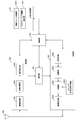
- FIG. 2 is a schematic block diagram showing the configuration of the base station device according to the present embodiment.
- the base station apparatus includes an upper layer processing unit (upper layer processing step) 101, a control unit (control step) 102, a transmitting unit (transmitting step) 103, a receiving unit (receiving step) 104, and a transmitting / receiving antenna. 105 and a measurement unit (measurement step) 106.
- the upper layer processing unit 101 includes a radio resource control unit (radio resource control step) 1011 and a scheduling unit (scheduling step) 1012.
- transmitting section 103 includes coding section (coding step) 1031, modulation section (modulation step) 1032, downlink reference signal generation section (downlink reference signal generation step) 1033, multiplexing section (multiplexing step) 1034, radio A transmission unit (wireless transmission step) 1035 is included.
- the receiving unit 104 includes a wireless receiving unit (wireless receiving step) 1041, a demultiplexing unit (multiplexing / demultiplexing step) 1042, a demodulating unit (demodulating step) 1043, and a decoding unit (decoding step) 1044.
- the upper layer processing unit 101 includes a medium access control (Medium Access Control: MAC) layer, a packet data integration protocol (Packet Data Convergence Protocol: PDCP) layer, a radio link control (Radio Link Control: RLC) layer, and a radio resource control (Radio). Resource Control: RRC) layer processing. Further, upper layer processing section 101 generates information necessary for controlling transmission section 103 and reception section 104 and outputs the information to control section 102.
- Medium Access Control: MAC Medium Access Control
- PDCP Packet Data Convergence Protocol
- RLC Radio Link Control
- Radio Radio Resource Control
- the upper layer processing unit 101 receives information about the terminal device, such as the function of the terminal device (UE capability), from the terminal device. In other words, the terminal device transmits its function to the base station device by a higher layer signal.
- the terminal device such as the function of the terminal device (UE capability)
- the information on the terminal device includes information indicating whether the terminal device supports a predetermined function, or information indicating that the terminal device has completed the introduction and test for the predetermined function.
- whether or not a predetermined function is supported includes whether or not introduction and testing of the predetermined function have been completed.
- the terminal device when the terminal device supports a predetermined function, the terminal device transmits information (parameter) indicating whether the terminal device supports the predetermined function.
- the terminal device does not transmit information (parameter) indicating whether the terminal device supports the predetermined function. That is, whether or not to support the predetermined function is notified by transmitting or not transmitting information (parameter) indicating whether or not to support the predetermined function.
- the information (parameter) indicating whether or not a predetermined function is supported may be notified using one bit of 1 or 0.
- the radio resource control unit 1011 generates downlink data (transport block), system information, an RRC message, a MAC $ CE, etc., arranged in the downlink PDSCH, or obtains the information from an upper node. Radio resource control section 1011 outputs downlink data to transmitting section 103 and outputs other information to control section 102.
- the wireless resource control unit 1011 manages various setting information of the terminal device.
- the scheduling unit 1012 determines the frequency and subframe to which the physical channels (PDSCH and PUSCH) are to be allocated, the coding rate and modulation scheme (or MCS) of the physical channels (PDSCH and PUSCH), the transmission power, and the like.
- the scheduling unit 1012 outputs the determined information to the control unit 102.
- ⁇ Scheduling section 1012 generates information used for physical channel (PDSCH and PUSCH) scheduling based on the scheduling result. Scheduling section 1012 outputs the generated information to control section 102.
- PDSCH and PUSCH physical channel scheduling
- Control section 102 generates a control signal for controlling transmission section 103 and reception section 104 based on information input from upper layer processing section 101.
- the control unit 102 generates downlink control information based on the information input from the upper layer processing unit 101, and outputs the generated downlink control information to the transmission unit 103.
- the transmission unit 103 generates a downlink reference signal according to the control signal input from the control unit 102, and encodes the HARQ indicator, downlink control information, and downlink data input from the upper layer processing unit 101. And modulates the PHICH, PDCCH, EPDCCH, PDSCH, and downlink reference signal, and transmits the signal to the terminal device 2A via the transmission / reception antenna 105.
- the coding unit 1031 performs block coding, convolutional coding, turbo coding, and LDPC (Low Density Parity Check: Low Density Check) on the HARQ indicator, downlink control information, and downlink data input from the upper layer processing unit 101. Encoding is performed using a predetermined encoding method such as parity @ check) encoding or Polar encoding, or encoding is performed using an encoding method determined by the radio resource control unit 1011.
- a predetermined encoding method such as parity @ check
- Polar encoding or encoding is performed using an encoding method determined by the radio resource control unit 1011.
- the modulation unit 1032 converts the coded bits input from the coding unit 1031 into a predetermined value such as BPSK (Binary Phase Shift Keying), QPSK (quadrature Phase Shift Keying), 16 QAM (quadrature amplitude modulation), 64 QAM, or 256 QAM. Alternatively, modulation is performed using the modulation method determined by the radio resource control unit 1011.
- the downlink reference signal generation unit 1033 performs downlink reference to a sequence known to the terminal device 2A, which is obtained by a predetermined rule based on a physical cell identifier (PCI, cell ID) for identifying the base station device 1A and the like. Generate as a signal.
- PCI physical cell identifier
- the multiplexing unit 1034 multiplexes the modulated modulation symbol of each channel, the generated downlink reference signal, and the downlink control information. That is, multiplexing section 1034 arranges the modulated modulation symbol of each channel, the generated downlink reference signal, and the downlink control information in the resource element.
- the radio transmission unit 1035 generates an OFDM symbol by performing an inverse fast Fourier transform (Inverse Fast Fourier Transform: IFFT) on the multiplexed modulation symbol and the like, and adds a cyclic prefix (cyclic prefix: CP) to the OFDM symbol to generate a base.
- IFFT inverse Fast Fourier Transform
- CP cyclic prefix
- Receiving section 104 separates, demodulates, and decodes a received signal received from terminal apparatus 2A via transmission / reception antenna 105 in accordance with the control signal input from control section 102, and outputs the decoded information to upper layer processing section 101. .
- the receiving unit 104 also has a function (step) of performing carrier sense.
- the wireless reception unit 1041 converts an uplink signal received via the transmission / reception antenna 105 into a baseband signal by down-conversion, removes unnecessary frequency components, and amplifies the signal level so that the signal level is appropriately maintained.
- the level is controlled, quadrature demodulation is performed based on the in-phase and quadrature components of the received signal, and the quadrature demodulated analog signal is converted into a digital signal.
- the radio receiving unit 1041 removes a portion corresponding to the CP from the converted digital signal.
- the wireless receiving unit 1041 performs fast Fourier transform (Fast Fourier Transform: FFT) on the signal from which the CP has been removed, extracts a signal in the frequency domain, and outputs the signal to the demultiplexing unit 1042.
- FFT Fast Fourier transform
- the demultiplexing unit 1042 separates the signal input from the radio reception unit 1041 into signals such as PUCCH, PUSCH, and uplink reference signals. This separation is performed based on the radio resource allocation information included in the uplink grant determined by the base station apparatus 1A in advance in the radio resource control unit 1011 and notified to each terminal apparatus 2A.
- the demultiplexing section 1042 compensates for the propagation paths of PUCCH and PUSCH. Also, the demultiplexing section 1042 separates an uplink reference signal.
- the demodulation unit 1043 performs an inverse discrete Fourier transform (Inverse Discrete Fourier Transform: IDFT) on the PUSCH, obtains a modulation symbol, and performs BPSK, QPSK, 16QAM, 64QAM, 256QAM, or the like for each of the PUCCH and PUSCH modulation symbols.
- IDFT inverse discrete Fourier Transform
- the terminal performs demodulation of the received signal using a predetermined or predetermined modulation scheme notified to the terminal apparatus 2A by an uplink grant.
- the decoding unit 1044 converts the demodulated coded bits of the PUCCH and the PUSCH into a predetermined coding scheme, at a predetermined coding rate, or at a coding rate previously notified to the terminal apparatus 2A by the own apparatus through the uplink grant. It performs decoding and outputs the decoded uplink data and uplink control information to the upper layer processing unit 101.
- decoding section 1044 performs decoding using the coded bits held in the HARQ buffer input from higher layer processing section 101 and the coded bits demodulated.
- the measurement unit 106 observes the received signal and obtains various measurement values such as RSRP / RSRQ / RSSI. Further, measuring section 106 obtains reception power, reception quality, and a suitable SRS resource index from the SRS transmitted from the terminal device.
- FIG. 3 is a schematic block diagram illustrating the configuration of the terminal device according to the present embodiment.
- the terminal device includes an upper layer processing unit (upper layer processing step) 201, a control unit (control step) 202, a transmitting unit (transmission step) 203, a receiving unit (receiving step) 204, a measuring unit ( It comprises a (measurement step) 205 and a transmitting / receiving antenna 206.
- the upper layer processing unit 201 is configured to include a radio resource control unit (radio resource control step) 2011 and a scheduling information interpretation unit (scheduling information interpretation step) 2012.
- transmitting section 203 includes coding section (coding step) 2031, modulation section (modulation step) 2032, uplink reference signal generation section (uplink reference signal generation step) 2033, multiplexing section (multiplexing step) 2034, radio A transmission unit (wireless transmission step) 2035 is included.
- the receiving unit 204 includes a wireless receiving unit (wireless receiving step) 2041, a demultiplexing unit (multiplexing / demultiplexing step) 2042, and a signal detecting unit (signal detecting step) 2043.
- the upper layer processing unit 201 outputs the uplink data (transport block) generated by a user operation or the like to the transmission unit 203.
- the upper layer processing unit 201 includes a medium access control (Medium Access Control: MAC) layer, a packet data integration protocol (Packet Data Convergence Protocol: PDCP) layer, a radio link control (Radio Link Control: RLC) layer, and a radio resource control. (Radio ⁇ Resource ⁇ Control: ⁇ RRC) layer processing.
- Medium Access Control Medium Access Control: MAC
- PDCP Packet Data Convergence Protocol
- RLC Radio Link Control
- RRC radio resource control
- the upper layer processing unit 201 outputs information indicating the function of the terminal device supported by the own terminal device to the transmitting unit 203.
- the radio resource control unit 2011 manages various setting information of the terminal device itself. In addition, the radio resource control unit 2011 generates information to be allocated to each uplink channel and outputs the information to the transmission unit 203.
- the radio resource control unit 2011 acquires the setting information transmitted from the base station device and outputs the setting information to the control unit 202.
- the scheduling information interpreting section 2012 interprets the downlink control information received via the receiving section 204 and determines scheduling information. Further, scheduling information interpreting section 2012 generates control information for controlling receiving section 204 and transmitting section 203 based on the scheduling information, and outputs the generated control information to control section 202.
- the control unit 202 generates a control signal for controlling the receiving unit 204, the measuring unit 205, and the transmitting unit 203 based on the information input from the upper layer processing unit 201.
- the control unit 202 outputs the generated control signal to the receiving unit 204, the measuring unit 205, and the transmitting unit 203 to control the receiving unit 204 and the transmitting unit 203.
- the control unit 202 controls the transmitting unit 203 to transmit the CSI / RSRP / RSRQ / RSSI generated by the measuring unit 205 to the base station device.
- Receiving section 204 separates, demodulates, and decodes the received signal received from the base station apparatus via transmission / reception antenna 206 according to the control signal input from control section 202, and outputs the decoded information to upper layer processing section 201. I do.
- the receiving unit 204 also has a function (step) of performing carrier sensing.
- the wireless reception unit 2041 converts the downlink signal received via the transmission / reception antenna 206 into a baseband signal by down-conversion, removes unnecessary frequency components, and increases the amplification level so that the signal level is appropriately maintained. To perform quadrature demodulation based on the in-phase and quadrature components of the received signal, and convert the quadrature-demodulated analog signal into a digital signal.
- the wireless receiving unit 2041 removes a portion corresponding to the CP from the converted digital signal, performs fast Fourier transform on the signal from which the CP has been removed, and extracts a signal in the frequency domain.
- the demultiplexing unit 2042 demultiplexes the extracted signal into a PHICH, a PDCCH, an EPDCCH, a PDSCH, and a downlink reference signal. Further, the demultiplexing unit 2042 compensates for the channels of PHICH, PDCCH, and EPDCCH based on the channel estimation value of the desired signal obtained from the channel measurement, detects downlink control information, and controls the control unit 202. Output. Further, control section 202 outputs the channel estimation values of the PDSCH and the desired signal to signal detection section 2043.
- the signal detection unit 2043 detects a signal using the PDSCH and the channel estimation value, and outputs the signal to the upper layer processing unit 201.
- the measurement unit 205 performs various measurements such as CSI measurement, RRM (Radio Resource Management) measurement, RLM (Radio Link Monitoring) measurement, and obtains CSI / RSRP / RSRQ / RSSI and the like.
- CSI measurement Radio Resource Management
- RLM Radio Link Monitoring
- Transmitting section 203 generates an uplink reference signal according to the control signal input from control section 202, encodes and modulates uplink data (transport block) input from upper layer processing section 201, and performs PUCCH,
- the PUSCH and the generated uplink reference signal are multiplexed and transmitted to the base station apparatus via the transmission / reception antenna 206.
- the coding unit 2031 performs coding such as convolution coding, block coding, turbo coding, LDPC coding, and Polar coding on the uplink control information or the uplink data input from the upper layer processing unit 201.
- Modulating section 2032 modulates the coded bits input from coding section 2031 in a modulation scheme notified by downlink control information such as BPSK, QPSK, 16QAM, 64QAM, or a modulation scheme predetermined for each channel. .
- the uplink reference signal generating unit 2033 uses a physical cell identifier (physical cell identity: referred to as PCI, Cell ID, or the like) for identifying the base station device, a bandwidth in which the uplink reference signal is arranged, and an uplink grant. Based on the notified cyclic shift, the value of the parameter for generating the DMRS sequence, and the like, a sequence determined by a predetermined rule (expression) is generated.
- a physical cell identifier physical cell identity: referred to as PCI, Cell ID, or the like
- the multiplexing unit 2034 multiplexes the PUCCH and PUSCH signals and the generated uplink reference signal for each transmission antenna port. That is, multiplexing section 2034 arranges the PUCCH and PUSCH signals and the generated uplink reference signal in the resource element for each transmission antenna port.
- the radio transmission unit 2035 performs an inverse fast Fourier transform (Inverse Fast Fourier Transform: IFFT) on the multiplexed signal, performs OFDM modulation, generates an OFDMA symbol, adds a CP to the generated OFDMA symbol, Generate a baseband digital signal, convert the baseband digital signal to an analog signal, remove extra frequency components, convert to a carrier frequency by up-conversion, amplify power, output to transmit / receive antenna 206, and transmit I do.
- IFFT inverse Fast Fourier transform
- the terminal device can perform modulation not only in the OFDMA system but also in the SC-FDMA system.
- ultra-wideband transmission utilizing a high frequency band is desired.
- For transmission in a high frequency band it is necessary to compensate for path loss, and beamforming is important.
- an ultra-dense network (Ultra-dense network) in which base station devices are densely arranged. network) is valid.
- SNR signal-to-noise power ratio
- strong interference due to beamforming may come. Therefore, in order to realize ultra-large-capacity communication with all terminal devices in the limited area, interference control (avoidance, suppression, and elimination) in consideration of beamforming and / or cooperative communication of a plurality of base stations are required. Required.
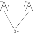
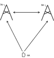
- FIG. 4 shows an example of a downlink communication system according to the present embodiment.
- the communication system shown in FIG. 4 includes a base station device 3A, a base station device 5A, and a terminal device 4A.
- the terminal device 4A can use the base station device 3A and / or the base station device 5A as a serving cell.
- the base station device 3A or the base station device 5A includes a large number of antennas
- the large number of antennas can be divided into a plurality of sub-arrays (panels, sub-panels), and transmission / reception beamforming can be applied to each sub-array.
- each sub-array can include a communication device, and the configuration of the communication device is the same as the configuration of the base station device illustrated in FIG.
- the terminal device 4A can transmit or receive by beamforming.
- the terminal device 4A includes a large number of antennas, the large number of antennas can be divided into a plurality of sub-arrays (panels, sub-panels), and different transmission / reception beamforming can be applied to each sub-array.
- Each sub-array can include a communication device, and the configuration of the communication device is the same as the terminal device configuration shown in FIG. 3 unless otherwise specified.
- the base station devices 3A and 5A are also simply referred to as base station devices.
- the terminal device 4A is also simply referred to as a terminal device.
- the synchronization signal is used to determine a suitable transmission beam for the base station device and a suitable reception beam for the terminal device.
- the base station device transmits a synchronization signal block (SS @ block, SSB) composed of PSS, PBCH, and SSS.
- SS @ block, SSB synchronization signal block
- One or a plurality of synchronization signal blocks are transmitted in the time domain within a synchronization signal block burst set period set by the base station apparatus, and a time index is set for each synchronization signal block.
- the terminal apparatus may determine that the synchronization signal block having the same time index within the synchronization signal block burst set period has a delay spread, a Doppler spread, a Doppler shift, an average gain, an average delay, a spatial reception parameter, and / or a spatial transmission parameter.
- the spatial reception parameters are, for example, the spatial correlation of the channel, the angle of arrival (Angle of Arrival) and the like.
- the spatial transmission parameter is, for example, a spatial correlation of the channel, a transmission angle (Angle of Departure), or the like. That is, the terminal device can assume that the synchronization signal blocks having the same time index are transmitted by the same transmission beam and the synchronization signal blocks having different time indexes are transmitted by different beams within the synchronization signal block burst set period.
- the base station device can know a transmission beam suitable for the terminal device. Further, the terminal device can obtain a reception beam suitable for the terminal device by using the synchronization signal blocks having the same time index in different synchronization signal block burst set periods. For this reason, the terminal device can associate the time index of the synchronization signal block with the reception beam direction and / or the sub-array. In addition, when the terminal device includes a plurality of sub-arrays, when connecting to a different cell, the terminal device may use a different sub-array.
- CSI-RS can be used to determine the preferred transmit beam of the base station device and the preferred receive beam of the terminal device.
- the base station apparatus can set the setting information using the signal of the upper layer.
- the setting information includes a part or all of a resource setting and a report setting.
- the resource configuration includes a resource configuration ID, a resource configuration type, and / or one or more CSI-RS resource set configurations.
- the resource setting ID is used to specify a resource setting.
- the resource setting type indicates an operation in the time domain of the resource setting.
- the resource setting is a setting for transmitting the CSI-RS aperiodicly, a setting for transmitting the CSI-RS periodically, or a semi-persistent CSI-RS. Indicates whether the setting is to send.
- the CSI-RS resource set configuration includes a CSI-RS resource set configuration ID and / or one or more CSI-RS resource configurations.
- the CSI-RS resource set setting ID is used to specify the CSI-RS resource set setting.
- the CSI-RS resource configuration includes a CSI-RS resource configuration ID, a resource configuration type, the number of antenna ports, CSI-RS resource mapping, and a part or all of the power offset between the CSI-RS and PDSCH.
- the CSI-RS resource setting ID is used to specify the CSI-RS resource setting, and the CSI-RS resource is associated with the CSI-RS resource setting ID.
- the CSI-RS resource mapping indicates a resource element (OFDM symbol, subcarrier) in which the CSI-RS in the slot is arranged.
- the resource setting is used for CSI measurement or RRM measurement.
- the terminal device receives the CSI-RS with the set resource, calculates the CSI from the CSI-RS, and reports the CSI to the base station device. Further, when the CSI-RS resource set configuration includes a plurality of CSI-RS resource configurations, the terminal device receives the CSI-RS with the same reception beam on each CSI-RS resource and calculates the CRI. For example, if the CSI-RS resource set configuration includes K (K is an integer of 2 or more) CSI-RS resource configurations, the CRI indicates N preferred CSI-RS resources from the K CSI-RS resources. . Here, N is a positive integer less than K.
- the terminal device should report the CSI-RSRP measured with each CSI-RS resource to the base station device in order to indicate which CSI-RS resource has good quality. Can be. If the base station apparatus transmits the CSI-RS by beamforming (precoding) in different beam directions with the plurality of set CSI-RS resources and transmits the CSI-RS, the base station apparatus suitable for the terminal apparatus based on the CRI reported from the terminal apparatus.
- the transmission beam direction can be known.
- a suitable receiving beam direction of the terminal device can be determined using a CSI-RS resource in which the transmitting beam of the base station device is fixed.
- the base station apparatus transmits, for a certain CSI-RS resource, information indicating whether or not the transmission beam of the base station apparatus is fixed, and / or a period during which the transmission beam is fixed.
- the terminal device can obtain a suitable reception beam direction from CSI-RSs received in different reception beam directions for CSI-RS resources in which the transmission beam is fixed.
- the terminal device may report the CSI-RSRP after determining a suitable reception beam direction.
- the terminal device can select a suitable sub-array when obtaining a suitable reception beam direction.
- the preferred receiving beam direction of the terminal device may be associated with the CRI.
- the base station device can fix the transmission beam using the CSI-RS resource associated with each CRI.
- the terminal device can determine a suitable receiving beam direction for each CRI.
- the base station apparatus can transmit a downlink signal / channel in association with a CRI.
- the terminal device has to receive with the reception beam associated with the CRI.
- different base station apparatuses can transmit CSI-RSs in a plurality of set CSI-RS resources. In this case, the network side can know which base station apparatus has good communication quality from the CRI.
- the terminal device when the terminal device has a plurality of sub-arrays, it is possible to receive signals at a plurality of sub-arrays at the same timing. Therefore, if the base station device transmits a CRI in association with each of a plurality of layers (codewords, transport blocks) in downlink control information or the like, the terminal device uses a sub-array and a reception beam corresponding to each CRI, Multiple layers can be received.
- the terminal device it may not be possible to receive with multiple receive beams.
- the base station apparatus divides a plurality of set CSI-RS resources into groups, and obtains a CRI within the group using the same sub-array. If different sub-arrays are used between groups, the base station apparatus can know a plurality of CRIs that can be set at the same timing.
- the CSI-RS resource group may be a CSI-RS resource set.
- the CRI that can be set at the same timing may be a QCL.
- the terminal device can transmit the CRI in association with the QCL information.
- the base station device may request CSI for each sub-array of the terminal device. In this case, the terminal device reports CSI for each sub-array.
- the terminal device may report only CRIs other than the QCL.
- the report setting is a setting related to the CSI report, and includes a report setting ID, a report setting type, and / or a report value (amount).
- the report setting ID is used to specify the report setting.
- the reported value (amount) is the reported CSI value (amount).
- the report setting type is such that the report setting is a setting for reporting an aperiodic CSI value (amount), a setting for periodically reporting a CSI value (amount), or a semi-persistent. ) Is a setting for reporting the CSI value (amount).
- the base station apparatus When reporting CSI aperiodically or semi-permanently, the base station apparatus transmits a trigger to start reporting the CSI to the terminal apparatus.
- the trigger can be DCI or higher layer signaling.
- a codebook in which candidates for a predetermined precoding (beamforming) matrix (vector) are specified is used.
- the base station device transmits the CSI-RS, and the terminal device obtains a suitable precoding (beamforming) matrix from the codebook and reports it to the base station device as PMI. Thereby, the base station apparatus can know the transmission beam direction suitable for the terminal apparatus.
- the codebook includes a precoding (beamforming) matrix for combining antenna ports and a precoding (beamforming) matrix for selecting antenna ports. When using a codebook for selecting an antenna port, the base station apparatus can use a different transmission beam direction for each antenna port.
- the base station device can know a preferred transmission beam direction.
- the preferred receiving beam of the terminal device may be the receiving beam direction associated with the CRI, or the preferred receiving beam direction may be determined again.
- the receiving beam direction for receiving the CSI-RS is the receiving beam direction associated with the CRI. It is desirable to receive in the direction.
- the terminal device can associate the PMI with the reception beam direction even when using the reception beam direction associated with the CRI.
- each antenna port may be transmitted from a different base station device (cell). In this case, if the terminal device reports the PMI, the base station device can know which base station device (cell) the communication quality is preferable. In this case, the antenna ports of different base station devices (cells) may not be QCLs.
- the CSI report includes a type 1 CSI report and a type 2 CSI report.
- CSI based on the type 1 codebook also referred to as type 1 CSI
- type 2 CSI report CSI based on the type 2 codebook (also referred to as type 2 CSI) is reported.
- the two parts are also referred to as a first part (part 1, CSI part 1) and a second part (part 2, CSI part 2). Note that the first part has a higher priority for CSI reporting than the second part.
- the first part is the sum of the first RI and the second RI (or the second RI), the second CRI, the CQI based on the first CRI and the second CRI. (Or part or all of the second CQI).
- the second part includes a part or all of the first CRI, the first RI, the first CQI, the first PMI, and the second PMI. If the RI is greater than four, the first part includes the sum of the first RI and the second RI (or a second RI), a second CRI, some or all of a second CQI.
- the second part includes a part or all of the first CRI, the first RI, the first CQI, the first PMI, and the second PMI.
- the third part is also called a third part (part 3, CSI part 3).
- the third part has a lower priority than the second part.
- the first part is a sum of the first RI and the second RI (or a second RI), a second CRI, a CQI based on the first CRI and the second CRI (or a second CQI).
- the second part includes the first CRI, the first RI, and some or all of the first CQI.
- the third part includes part or all of the first PMI and the second PMI.
- the terminal device may divide the CSI based on the first CRI and the CSI based on the second CRI into two parts and report the two parts.
- the two parts of the CSI based on the first CRI are also referred to as a first part 1 and a first part 2.
- the two parts of the CSI based on the second CRI are also referred to as a second part 1 and a second part 2.
- the first part 1 includes a part or all of the first CRI, the first RI, and the first CQI.
- the first part 2 includes a first PMI.
- the second part 1 includes a part or all of the second CRI, the second RI, and the second CQI.
- the second part 2 includes a second PMI.
- the priority of CSI can be set higher in the order of the second part 1, the first part 1, the second part 2, and the first part 2.
- the terminal device reports a long-period (with little change) CSI in the second CRI and the first CRI, and the base station device and the terminal device transmit at least the first CRI and the second CRI. Communication can be performed using limited parameters.
- the priority of CSI can be set higher in the order of the second part 1, the second part 2, the first part 1, and the first part 2.
- the terminal device reports the complete CSI in the second CRI with priority, so that the base station device and the terminal device can communicate using detailed parameters related to the second CRI.
- the terminal device 4A may receive an interference signal (adjacent cell interference) from an adjacent cell in addition to the serving cell.
- the interference signal is a PDSCH, PDCCH, or reference signal of a neighboring cell. In this case, removal or suppression of the interference signal in the terminal device is effective.
- E-MMSE Enhanced-Minimum-Mean-Square-Error
- E-MMSE Enhanced-Minimum-Mean-Square-Error
- an interference canceller for generating and removing a replica of the interference signal
- a desired signal And MLD Maximum Likelihood Detection
- R-MLD Reduced complexity- ⁇ ⁇ MLD
- the terminal device needs to know the parameters of the interference signal (adjacent cell). Therefore, the base station device can transmit (set) assist information including parameters of the interference signal (adjacent cell) to the terminal device in order to assist the terminal device in removing or suppressing the interference signal.
- assist information includes, for example, a physical cell ID, a virtual cell ID, a power ratio (power offset) between the reference signal and the PDSCH, a scrambling identity of the reference signal, QCL information (quasi co-location information), CSI-RS resource setting, and CSI.
- the virtual cell ID is an ID virtually assigned to a cell, and there may be cells having the same physical cell ID but different virtual cell IDs.
- the QCL information is information on the QCL for a predetermined antenna port, a predetermined signal, or a predetermined channel.
- the long-term properties include delay spread, Doppler spread, Doppler shift, average gain, average delay, spatial reception parameters, and / or spatial transmission parameters. That is, when two antenna ports are QCLs, the terminal device can regard that the long-term characteristics at those antenna ports are the same.
- the subcarrier interval indicates a subcarrier interval of the interference signal or a candidate of a subcarrier interval that may be used in the band.
- the terminal device need not remove or suppress the interference signal.
- the subcarrier interval candidates that may be used in the band may indicate a commonly used subcarrier interval.
- the normally used subcarrier interval does not have to include a low frequency subcarrier interval used in highly reliable and low delay communication (emergency communication).
- the resource allocation granularity indicates the number of resource blocks for which precoding (beamforming) does not change.
- the DMRS setting indicates the PDSCH mapping type and the additional arrangement of the DMRS. DMRS resource allocation changes according to the PDSCH mapping type. For example, in the PDSCH mapping type A, the DMRS is mapped to the third symbol of the slot.
- the PDSCH mapping type B is mapped to the first OFDM symbol of the allocated PDSCH resource.
- the additional arrangement of the DMRS indicates whether there is an additional DMRS arrangement or the arrangement to be added.
- some or all of the parameters included in the assist information are transmitted (set) by higher layer signals.
- some or all parameters included in the assist information are transmitted as downlink control information.
- the terminal device blindly detects a suitable candidate from the candidates.
- the terminal device performs blind detection on parameters not included in the assist information.
- the surrounding interference situation greatly changes depending on the reception beam directions. For example, an interference signal that was strong in one receive beam direction may be weak in another receive beam direction.
- the assist information of the cell that is unlikely to cause strong interference is not only meaningless, but may cause unnecessary calculation when determining whether or not a strong interference signal is being received. Therefore, it is desirable that the assist information be set for each receiving beam direction.
- the base station apparatus since the base station apparatus does not necessarily know the receiving direction of the terminal apparatus, information relating to the receiving beam direction may be associated with the assist information. For example, since the terminal device can associate the CRI with the reception beam direction, the base station device can transmit (set) one or a plurality of pieces of assist information for each CRI.
- the base station device can transmit (set) one or a plurality of pieces of assist information for each time index of the synchronization signal block. .
- the base station device can transmit (set) one or a plurality of pieces of assist information for each PMI (antenna port number). .
- the base station device transmits one or more pieces of assist information for each index associated with the sub-array of the terminal device (setting )can do.
- the base station apparatus transmits (sets) one or a plurality of pieces of assist information for each piece of information indicating the base station apparatus (transmission / reception point).
- the information indicating the base station device (transmission / reception point) may be a physical cell ID or a virtual cell ID.
- information indicating the DMRS antenna port number or the DMRS antenna group is information indicating the base station device (transmission / reception point).
- the number of pieces of assist information set by the base station apparatus for each CRI can be common.
- the number of pieces of assist information indicates the type of assist information, the number of elements of each piece of assist information (for example, the number of cell ID candidates), and the like.
- a maximum value is set for the number of pieces of assist information set by the base station apparatus for each CRI, and the base station apparatus can set the assist information for each CRI within the range of the maximum value.
- the assist information can be associated with the QCL information. For example, when the base station device transmits (sets) the assist information of a plurality of cells, it is possible to instruct the terminal device which cell is the QCL (or which cell is not the QCL).
- the terminal device removes or suppresses the interference signal using the assist information associated with the CRI used for communication with the serving cell.
- the base station apparatus provides assist information associated with the reception beam direction (CRI / time index of synchronization signal block / PMI / antenna port number / subarray) and reception beam direction (CRI / time index of synchronization signal block / PMI / Assist information that is not associated with the antenna port number / sub-array) may be set.
- the assist information associated with the receiving beam direction and the assist information not associated with the receiving beam direction may be selectively used depending on the capability or category of the terminal device.
- the capabilities and categories of the terminal device may indicate whether the terminal device supports reception beamforming.
- the assist information associated with the receiving beam direction and the assist information not associated with the receiving beam direction may be selectively used in a frequency band.
- the base station device does not set the assist information associated with the reception beam direction at a frequency lower than 6 GHz.
- the base station apparatus sets the assist information associated with the reception beam direction only at a frequency higher than 6 GHz.
- the CRI may be associated with the CSI resource set setting ID.
- the base station device may instruct the CRI together with the CSI resource set setting ID.
- the base station device may set the assist information for each CSI resource set setting ID.
- the base station device requests the neighboring cell measurement from the terminal device to know the neighboring cell related to the receiving beam direction of the terminal device.
- the neighbor cell measurement request includes information related to the reception beam direction of the terminal device and the cell ID.
- the terminal device measures the RSRP / RSRQ / RSSI of the neighbor cell and reports the same to the base station device together with information related to the reception beam direction of the terminal device.
- the information related to the reception beam direction of the terminal device is information indicating a CRI, a time index of a synchronization signal block, a sub-array of the terminal device, or a base station device (transmission / reception point).
- the terminal device when the terminal device moves, the surrounding environment may change every moment. Therefore, it is desirable that the terminal device observe the surrounding channel condition, interference condition, and the like at a predetermined timing and report it to the base station device. Reporting results are reported either on a regular basis or as an event report. In the case of a periodic report, the terminal device periodically measures and reports RSRP / RSRQ based on a synchronization signal or CSI-RS. In the case of reporting by event, an event ID is associated with a condition for reporting. The event IDs include, for example, the following, and a threshold necessary for calculating the condition (threshold 1, threshold 2 if necessary) and an offset value are also set. Event A1: When the measurement result of the serving cell becomes better than the set threshold.
- Event A2 When the measurement result of the serving cell becomes worse than the set threshold.
- Event A3 A case where the measurement result of the adjacent cell is better than the measurement result of PCell / PSCell by the set offset value or more.
- Event A4 When the measurement result of the neighboring cell becomes better than the set threshold value.
- Event A5 A case where the measurement result of PCell / PSCell becomes worse than the set threshold 1 and the measurement result of the adjacent cell becomes better than the set threshold 2.
- Event A6 When the measurement result of the neighboring cell is better than the measurement result of SCell by a set offset value or more.
- Event C1 When the measurement result of the CSI-RS resource becomes better than the set threshold.
- Event C2 A case where the measurement result of the CSI-RS resource is better than the measurement result of the set reference CSI-RS resource by the offset amount or more.
- Event D1 When a measurement result of a CSI-RS resource different from the CRI becomes better than a set threshold.
- Event D2 When the measurement result of the CSI-RS resource related to the CRI becomes worse than the set threshold.
- Event D3 When the measurement result of the reception beam direction not related to the CRI becomes better than the set threshold value.
- Event D4 When the measurement result of the SS block index used for synchronization becomes lower than the set threshold.
- Event D5 When the measurement result of the SS block index not used for synchronization becomes worse than the set threshold.
- Event E1 When the time elapsed since the base station apparatus determined the beam exceeds the threshold.
- Event E2 When the time elapsed since the terminal device determined the beam exceeds the threshold.
- the terminal device When the terminal device reports based on the report settings, the terminal device reports SS-RSRP / SS-RSRQ / CSI-RSRP / CSI-RSRQ / RSSI as a measurement result.
- FIG. 5 shows an example of an uplink communication system according to the present embodiment.
- the communication system illustrated in FIG. 5 includes a base station device 7A, a base station device 9A, and a terminal device 6A.
- the terminal device 6A can use the base station device 7A and / or the base station device 9A as a serving cell.
- the base station device 7A or the base station device 9A includes a large number of antennas
- the large number of antennas can be divided into a plurality of sub-arrays (panels, sub-panels), and transmission / reception beamforming can be applied to each sub-array.
- each sub-array can include a communication device, and the configuration of the communication device is the same as the configuration of the base station device illustrated in FIG.
- the terminal device 6A can transmit or receive by beamforming.
- the terminal device 6A includes a large number of antennas, the large number of antennas can be divided into a plurality of sub-arrays (panels, sub-panels), and different transmission / reception beamforming can be applied to each sub-array.
- Each sub-array can include a communication device, and the configuration of the communication device is the same as the terminal device configuration shown in FIG. 3 unless otherwise specified.
- the base station devices 7A and 9A are also simply referred to as base station devices.
- the terminal device 6A is also simply referred to as a terminal device.
- the SRS is used to determine a preferred transmission beam for the terminal device and a preferred reception beam for the base station device.
- the base station apparatus can transmit (set) the setting information related to the SRS using the signal of the upper layer.
- the setting information includes one or a plurality of SRS resource set settings.
- the SRS resource set configuration includes an SRS resource set configuration ID and / or one or more SRS resource configurations.
- the SRS resource set setting ID is used to specify the SRS resource set setting.
- the SRS resource configuration includes an SRS resource configuration ID, the number of SRS antenna ports, an SRS transmission comb, an SRS resource mapping, an SRS frequency hopping, and an SRS resource configuration type.
- the SRS resource setting ID is used to specify the SRS resource setting.
- the SRS transmission comb indicates the frequency interval of the comb tooth spectrum and the position (offset) within the frequency interval.
- the SRS resource mapping indicates an OFDM symbol position and an OFDM symbol number in which an SRS is arranged in a slot.
- the SRS frequency hopping is information indicating SRS frequency hopping.
- the SRS resource setting type indicates an operation in the time domain of the SRS resource setting. Specifically, the SRS resource setting is a setting for transmitting the SRS aperiodicly, a setting for transmitting the SRS periodically, or a setting for transmitting the SRS semi-persistently. Indicates if there is.
- the terminal apparatus transmits a different transmission beam direction for each SRS resource, and the base station apparatus can determine a suitable SRS resource. If the base station device transmits (instructs) an SRS resource indicator (SRS Resource Indicator: $ SRI), which is information indicating the SRS resource, to the terminal device, the terminal device preferably has a transmission beam direction transmitted by the SRS resource. You can know.
- the base station apparatus can request the terminal apparatus to transmit with the same transmission beam for a predetermined period in order to obtain a suitable reception beam of the base station apparatus. In response to a request from the base station apparatus, the terminal apparatus transmits in the specified SRS resource in the same transmission beam direction as the one transmitted with the specified SRI, for the specified period.
- the terminal device can communicate with a plurality of base station devices (transmission / reception points).
- the terminal device 6A can use the base station device 7A and the base station device 9A as serving cells.
- the transmission beam direction suitable for communication with the base station device 7A and the transmission beam direction suitable for communication with the base station device 9A are likely to be different for the terminal device 6A. Therefore, the terminal device 6A can communicate with the base station device 7A and the base station device 9A at the same timing by transmitting signals in different sub-arrays in different transmission beam directions.
- the terminal device can use a different transmission beam direction for each antenna port.
- the base station apparatus instructs the terminal apparatus to perform transmission with a suitable antenna port number
- the terminal apparatus can know a suitable transmission beam direction.
- the base station device can also instruct the terminal device to transmit PMI (TPMI) using a codebook for selecting an antenna port.
- TPMI PMI
- the base station device can instruct the terminal device which codebook to refer to.
- the terminal device can use the transmission beam direction corresponding to the antenna port number indicated by TPMI with reference to the specified codebook.
- the terminal device has a plurality of sub-arrays and can transmit at the same timing in a plurality of sub-arrays, different antenna port numbers can be assigned to the sub-arrays.
- the terminal device transmits an SRS using a transmission beam from an antenna port of a different sub-array and receives a TPMI from the base station device, the terminal device can know a suitable sub-array and transmission beam direction. Therefore, the terminal device can associate the TPMI with the sub-array and the transmission beam direction.
- a terminal device When a terminal device communicates with a plurality of base station devices (transmission / reception points), the same signal (data) can be transmitted to each base station device (transmission / reception point), and different signals (data) can be transmitted. Can be sent.
- a terminal device communicates with a plurality of base station devices (transmission / reception points) using the same signal (data)
- signals received by the plurality of base station devices (transmission / reception points) are combined to improve reception quality. Therefore, it is desirable that a plurality of base station apparatuses (transmission / reception points) perform reception processing in cooperation.
- the base station apparatus can use DCI for PUSCH scheduling.
- each base station device can transmit DCI for PUSCH scheduling.
- DCI includes SRI and / or TPMI, and a terminal device can know a transmission beam suitable for the base station device.
- the PUSCH can be transmitted to the plurality of base station devices by DCI from one base station device. For example, when DCI includes control information for a plurality of layers (codewords, transport blocks) and SRI and / or TPMI is instructed (set) for each layer, each layer corresponds to each base station apparatus. Is transmitted by a suitable transmission beam.
- the terminal device can transmit different signals (data) to a plurality of base station devices when receiving one DCI.
- the DCI includes control information of one layer, and when a plurality of SRIs and / or TPMIs are instructed (set) for one layer, the terminal device uses one transmission layer with a different layer (the same Data). This allows the terminal device to transmit the same signal (data) to a plurality of base station devices when receiving one DCI.
- each base station device When a terminal device transmits to a plurality of base station devices at the same timing, it is desirable that each base station device knows the communication quality with the terminal device at the same timing. For this reason, the base station apparatus can instruct (trigger) a plurality of SRIs and SRS resources corresponding to each SRI with one DCI. That is, if the terminal device transmits the SRS in the transmission beam direction corresponding to each SRI at the same timing, each base station device can know the communication quality with the terminal device at the same timing.
- the sub-arrays provided in the terminal device use only one transmission beam direction at the same timing, they are transmitted to a plurality of base station devices at different sub-arrays at the same timing.
- the terminal device transmits at the same timing the transmissions corresponding to the two SRIs. May not be possible.
- the base station apparatus can set a plurality of SRS resources in groups and request the terminal apparatus to transmit the SRS using the same sub-array within the group.
- the base station apparatus can know a plurality of SRIs that can be set at the same timing.
- the group of SRS resources may be an SRS resource set.
- SRSs (SRS resources) that can be set at the same timing may not be QCLs.
- the terminal device can transmit the SRS in association with the QCL information. For example, if the terminal device separately transmits the SRS that is the QCL and the SRS that is not the QCL, the base station device does not set the SRI that is the QCL at the same timing, and sets the SRI that is not the QCL at the same timing. Can be. Further, the base station device may request the SRS for each sub-array of the terminal device. In this case, the terminal device transmits an SRS for each sub-array.
- the terminal apparatus when two SRIs that cannot be transmitted at the same timing are instructed from the base station apparatus, the terminal apparatus performs a beam recovery procedure for selecting a transmission beam again for the base station apparatus. Can be requested.
- the beam recovery procedure is a procedure that is performed when tracking of transmission / reception beams between the terminal device and the base station device is lost and communication quality is significantly reduced. It is necessary to acquire the transmission beam of the station device.
- the terminal device according to the present embodiment secures the transmission beam itself, but performs a beam recovery procedure in order to eliminate a state in which two SRIs that cannot be transmitted at the same timing are set. Can be used.
- the terminal device can include a plurality of antennas (antenna panels) in which independent beamforming is set.
- the terminal device according to the present embodiment can use a plurality of antenna panels.
- the terminal device can switch between the plurality of antenna panels and use them.
- the terminal device can perform beam scanning (exploration) with the base station device in order to select beamforming set to the antenna.
- the terminal device according to the present embodiment can transmit an SRS in order to perform the beam scanning.
- the base station apparatus can notify the terminal apparatus of information indicating duality (relationship, reciprocity) related to downlink and uplink propagation (channel) characteristics.
- the base station apparatus can notify the terminal apparatus of information indicating beam correspondence (BeamBeCorrespondence, spatial relation (Spatial relation), spatial relation information (Spatial relation information), reception parameters).
- BeamBeCorrespondence spatial relation (Spatial relation), spatial relation information (Spatial relation information), reception parameters).
- the beam correspondence includes reception beamforming (spatial domain reception filter, reception weight, reception parameter, reception space parameter) used when the terminal apparatus receives a downlink signal, and transmission used when transmitting an uplink signal. It includes information indicating an association with beamforming (spatial domain transmission filter, transmission weight, transmission parameter, transmission spatial parameter).
- the base station apparatus can set beam correspondence for each signal transmitted by the terminal apparatus. For example, the base station device can notify the terminal device of information indicating the beam correspondence to the SRS transmitted by the terminal device.
- the base station device can notify the terminal device of SRS space-related information (SRS-SpatialRelationInfo).
- SRS space-related information indicates a predetermined signal (value, state)
- the terminal device can perform SRS transmission using beamforming associated with the predetermined signal. For example, if the SRS space-related information specifies a synchronization signal (SSB and PBCH), the terminal device can transmit the SRS using the reception beamforming used when receiving the synchronization signal.
- SSB and PBCH synchronization signal
- the base station apparatus transmits space-related information on other signals (eg, PUCCH / PUSCH / RS / RACH) transmitted by the terminal apparatus and other signals (eg, PDCCH / PDSCH / RS) received by the terminal apparatus. Can be notified. That is, the base station device can notify the terminal device of the space-related information of the first signal and the second signal.
- the terminal device receives the spatially related information of the first signal and the second signal, and recognizes that the spatially related information guarantees the spatial relationship between the first signal and the second signal. It is possible to transmit the second signal (or receive the second signal) by using the reception parameter for receiving the first signal (or the transmission parameter for transmitting the first signal).
- the QCL includes at least the following four types, each having different parameters that can be considered the same.
- the base station device and the terminal device can set any one of the following QCL types between antenna ports (or signals associated with the antenna ports), or can set a plurality of QCL types simultaneously. it can.
- QCL type A Doppler shift, Doppler spread, average delay
- QCL type B Doppler shift
- QCL type C Doppler shift, average delay
- D Spatial Rx
- the terminal apparatus can set reception beamforming for receiving the PDSCH.
- the terminal device can acquire information associated with the reception beamforming from the DCI in which the downlink assignment is described.
- the terminal device can acquire a transmission configuration instruction (transmission ⁇ configuration ⁇ indication ⁇ (TCI)) from the DCI.
- TCI indicates information associated with the QCL related to the antenna port from which the PDSCH was transmitted.
- TCI can set reception beamforming for receiving the PDSCH (or the DMRS associated with the PDSCH).
- the terminal device receives the PDSB using the reception beam used when receiving the SSB of the index fed back to the base station device. Can be used. Note that if the DCI is not acquired before the terminal device starts receiving the PDSCH (before the frame including the PDSCH is received by the terminal device) (the scheduling offset value indicating the time difference between the scheduling information and the PDSCH is not sufficient). If the value is less than the predetermined value), the terminal device can receive the PDSCH according to the default setting of TCI default. Note that TCI-default is one of eight TCIs set. Also, when receiving the PDCCH, the terminal device can set the reception beamforming based on the setting of TCI default.
- a codebook in which candidates for a predetermined precoding (beamforming) matrix (vector) are specified is used.
- the base station device transmits the CSI-RS, and the terminal device obtains a suitable precoding (beamforming) matrix from the codebook and reports it to the base station device as PMI. Thereby, the base station apparatus can know the transmission beam direction suitable for the terminal apparatus.
- the codebook includes a precoding (beamforming) matrix for combining antenna ports and a precoding (beamforming) matrix for selecting antenna ports. When using a codebook for selecting an antenna port, the base station apparatus can use a different transmission beam direction for each antenna port.
- the base station device can know a preferred transmission beam direction.
- the preferred receiving beam of the terminal device may be the receiving beam direction associated with the CRI, or the preferred receiving beam direction may be determined again.
- the receiving beam direction for receiving the CSI-RS is the receiving beam direction associated with the CRI. It is desirable to receive in the direction.
- the terminal device can associate the PMI with the reception beam direction even when using the reception beam direction associated with the CRI.
- each antenna port may be transmitted from a different base station device (cell). In this case, if the terminal device reports the PMI, the base station device can know which base station device (cell) the communication quality is preferable. In this case, the antenna ports of different base station devices (cells) may not be QCLs.
- the base station device and the terminal device can transmit and receive signals using a plurality of antenna panels. That is, the base station apparatus and the terminal apparatus can select whether to transmit a predetermined signal using the same spatial domain transmission filter or to transmit using a different spatial domain transmission filter. Similarly, the base station apparatus and the terminal apparatus can select whether to receive a predetermined signal using the same spatial domain reception filter or to transmit using a different spatial domain reception filter.
- the antenna panel can be changed by changing the spatial domain transmission filter (reception filter), but it is not always necessary to change the antenna panel.
- the terminal device under a predetermined condition, when transmitting a predetermined signal, either transmits using the same spatial domain transmission filter or transmits using a different spatial domain transmission filter Can be set.
- the base station apparatus can notify the terminal device of SRS setting information on the SRS transmitted by the terminal device.
- the base station apparatus can include the setting information associated with the spatial domain transmission filter in the SRS setting information.
- the base station device and the terminal device can set information for identifying the spatial domain transmission filter (and the spatial domain reception filter). This allows the base station apparatus and the terminal apparatus to distinguish between the first spatial domain transmission filter and the second spatial domain transmission filter, for example.
- the first spatial domain transmission filter and the second spatial domain transmission filter are desirably filters exhibiting different characteristics, but are not necessarily limited thereto.
- the information for identifying the spatial domain transmission filter can be an identification number (ID). Further, the information for identifying the spatial domain transmission filter (spatial domain reception filter) can be set as scrambling setting information when the base station apparatus notifies the terminal apparatus of the information. Further, the information for identifying the spatial domain transmission filter (spatial domain reception filter) can be a resource position where control information used when the base station apparatus notifies the terminal apparatus of the information is arranged.
- the base station apparatus sets a reference spatial domain receiving filter (first spatial domain receiving filter, default spatial receiving filter) for the terminal device. can do.
- the first spatial domain reception filter may be a spatial domain reception filter in which the terminal device has received the SS / PBCH signal. Further, the first spatial domain reception filter may be a spatial domain reception filter used in TCI Default.
- the first spatial domain reception filter can be set, for example, at the 0th TCI-State among the M TCI-States, or at a predetermined non-zero TCI-State. be able to.
- the first spatial domain reception filter can be set to a predetermined QCL-Type for a predetermined signal (for example, set to QCL-TypeD for a CSI-RS).
- the base station apparatus can set a second spatial domain reception filter different from the first spatial domain reception filter for the terminal apparatus.
- the base station apparatus can set the terminal apparatus to use either the first spatial area reception filter or the second spatial area reception filter for the terminal apparatus.
- the base station device can set the first spatial domain transmission filter in the terminal device.
- the first spatial domain transmission filter may be a spatial domain transmission filter used when the terminal device transmits a signal including information indicating the index of the SS / PBCH signal to the base station device.
- the first spatial domain transmit filter and the first spatial domain receive filter may be Beam Correspondence.
- the second spatial domain transmission filter and the second spatial domain reception filter can be set to Beam @ Correspondence.
- the Beam @ Correspondence described above can be determined by a frequency band in which a terminal device (and a base station device) transmits a signal. For example, when the terminal device transmits (or receives) a signal in a first frequency band of less than 6 GHz and a second frequency band of 27 GHz or more, the first frequency band is a high frequency band.
- the spatial domain transmit filter and the first spatial domain receive filter may be Beam @ Correspondence.
- the base station apparatus can include information for identifying a spatial domain transmission filter in the SRS setting information.
- the terminal device can set a spatial domain transmission filter for transmitting an SRS associated with the SRS configuration information based on information for identifying the spatial domain transmission filter included in the SRS configuration information.
- the base station apparatus can include information for identifying the spatial domain transmission filter associated with the SRS in the signal that triggers the terminal apparatus to transmit the SRS.
- the trigger may be DCI.
- the base station apparatus can include information for identifying the spatial domain transmission filter in the DCI.
- the terminal device When transmitting an SRS, the terminal device according to the present embodiment can transmit the SRS in a resource orthogonal to the SRS transmitted by another terminal device.
- the terminal device can generate the SRS as a signal having a comb-like spectrum, and transmit the SRS from a frequency starting point different from the SRS transmitted by another terminal device.
- the terminal device can spread and transmit the SRS with an orthogonal cover code (OCC) different from other terminal devices.
- OCC orthogonal cover code
- the orthogonal resources from which the terminal device transmits the SRS can be set by the base station device.
- the base station apparatus can set information associated with the spatial domain transmission filter for each orthogonal resource.
- each bit information can further include information indicating a spatial domain transmission filter. If there are four OCC patterns to perform, the base station apparatus can notify the terminal apparatus which OCC to use by using 2-bit bit information. At this time, for example, the bit information is "00". , The spatial domain transmission filter can be set to “0”, and when the bit information indicates “01”, the spatial domain transmission filter can be set to “1”. This is the same when the terminal device orthogonalizes the SRS in the frequency domain or when the terminal device orthogonalizes the SRS by phase rotation.
- the terminal device can transmit a plurality of SRSs in the same OFDM symbol. At this time, when transmitting a plurality of SRSs, the terminal apparatus can transmit with the same spatial domain transmission filter or with different spatial domain transmission filters. When instructing a terminal device to simultaneously transmit a plurality of SRSs, the base station apparatus can set transmission using the same spatial domain transmission filter or configure transmission using a different spatial domain transmission filter. You can also.
- the base station apparatus can set SRS spatial correspondence for the terminal apparatus.
- the signal for which the spatial correspondence of the SRS is set can be, for example, an SS / PBCH signal, an NZP @ CSI-RS, a periodic SRS, a PDCCH signal, a PDSCH signal, and a DMRS.
- the terminal device uses the spatial domain reception filter used when the SS / PBCH signal is received as a spatial domain transmission filter that transmits the SRS. be able to.
- the base station apparatus sets information for identifying a spatial domain reception filter for a signal (for example, an SS / PBCH signal, an NZP @ CSI-RS, a periodically transmitted SRS) related to spatial correspondence with the SRS. be able to.
- the base station device can notify the terminal device of CSI-RS setting information that is setting information related to the CSI-RS.
- the base station device includes the CSI-RS setting information in the CSI-RS setting information. May be included to identify the spatial domain receive filter that receives the filter.
- the base station apparatus can set the spatial domain transmission filter for transmitting the SRS by the terminal apparatus.
- the terminal apparatus When notifying the base station apparatus of the index of the SS / PBCH signal and the information indicating the resource of the NZP @ CSI-RS, the terminal apparatus receives the SS / PBCH signal and the NZP @ CSI-RS. It can be notified whether the area reception filter is the first spatial area reception filter or the second spatial area reception filter. The terminal device can notify the base station device whether or not the spatial domain reception filter when receiving the signal is the first spatial domain reception filter.
- the base station apparatus can set SRS transmission using a different spatial domain transmission filter for a terminal apparatus that sets periodic SRS transmission.
- the base station apparatus can set the terminal apparatus to switch the spatial domain transmission filter every time a periodic SRS is transmitted.
- the base station apparatus sets the first spatial-domain transmission filter for the terminal apparatus, where n is a natural number and the terminal apparatus transmits the 2 (n-1) -th SRS, and the terminal apparatus sets 2n-1.
- the SRS to transmit the second time can be set to transmit the second spatial domain transmission filter.
- the base station apparatus can set, for the terminal apparatus, simultaneous reception of signals for which spatial correspondence with the SRS is set by a plurality of spatial domain reception filters.
- the base station apparatus can include, in the CSI-RS setting information, information indicating whether to perform simultaneous reception using a plurality of spatial domain reception filters.
- the plurality of spatial domain receiving filters include a first spatial domain receiving filter.
- the terminal device feeds back feedback information calculated based on the CSI-RS received by different spatial domain reception filters to the base station device, any one of the spatial domain reception filters used for reception of the CSI-RS is used.
- Information may be included in the feedback information.
- the terminal device can include, in the feedback information, information indicating whether the spatial domain reception filter used for receiving the CSI-RS is the first spatial domain reception filter.
- the methods described above can be linked between frequencies.
- information for the base station apparatus and the terminal apparatus to identify the spatial domain transmission filter and the spatial domain receiving filter may be common between CCs or between BWPs.
- the terminal apparatus can use the identification performed for a spatial domain reception filter set in the terminal apparatus in another BWP.
- the base station apparatus can notify the terminal apparatus of information indicating whether to permit or prohibit the identification of a common spatial area reception filter in a plurality of BWPs.
- the method described above allows the terminal device to apply different spatial domain transmission filters to a plurality of SRSs. This operation is performed according to the number of ranks that the terminal device can transmit. You can decide whether to do it or not. [2. Common to all embodiments]
- the program that operates on the device according to the present invention may be a program that controls a central processing unit (CPU) or the like to cause a computer to function so as to realize the functions of the embodiment according to the present invention.
- the program or information handled by the program is temporarily stored in a volatile memory such as a Random Access Memory (RAM), a non-volatile memory such as a flash memory, a Hard Disk Drive (HDD), or another storage device system.
- RAM Random Access Memory
- HDD Hard Disk Drive
- a program for realizing the functions of the embodiment according to the present invention may be recorded on a computer-readable recording medium.
- the program may be realized by causing a computer system to read and execute the program recorded on the recording medium.
- the “computer system” is a computer system built in the device, and includes an operating system and hardware such as peripheral devices.
- the “computer-readable recording medium” is a semiconductor recording medium, an optical recording medium, a magnetic recording medium, a medium that dynamically holds a program for a short time, or another computer-readable recording medium. Is also good.
- Each functional block or various features of the device used in the above-described embodiment may be implemented or executed by an electric circuit, for example, an integrated circuit or a plurality of integrated circuits.
- An electrical circuit designed to perform the functions described herein may be a general purpose processor, digital signal processor (DSP), application specific integrated circuit (ASIC), field programmable gate array (FPGA), or other Logic devices, discrete gate or transistor logic, discrete hardware components, or a combination thereof.
- a general purpose processor may be a microprocessor, or may be a conventional processor, controller, microcontroller, or state machine.
- the above-described electric circuit may be constituted by a digital circuit, or may be constituted by an analog circuit.
- one or more aspects of the present invention can use a new integrated circuit based on the technology.
- the present invention is not limited to the above embodiment.
- an example of the device is described.
- the present invention is not limited to this, and stationary or non-movable electronic devices installed indoors and outdoors, for example, AV devices, kitchen devices, It can be applied to terminal devices or communication devices such as cleaning / washing equipment, air conditioning equipment, office equipment, vending machines, and other living equipment.
- the present invention is suitable for use in a base station device, a terminal device, and a communication method.
Landscapes
- Engineering & Computer Science (AREA)
- Signal Processing (AREA)
- Computer Networks & Wireless Communication (AREA)
- Mobile Radio Communication Systems (AREA)
Abstract
高精度にビームフォーミングを実施し、周波数利用効率を向上することが可能な基地局装置、端末装置及び通信方法を提供する。本発明の一態様に係る端末装置は、SRS設定情報と、SRSと空間対応が設定される信号の設定情報を受信し、前記SRS設定情報には前記SRSの空間対応を示す情報が含まれ、複数の空間領域受信フィルタが設定可能であり、複数の空間領域送信フィルタが設定可能であり、前記SRSと空間対応が設定される信号の設定情報には前記複数の空間領域受信フィルタが識別される情報が含まれ、前記SRSの空間対応を示す情報と前記SRSと空間対応が設定される信号に基づいて、前記SRSを前記空間領域送信フィルタと前記第2の空間領域送信で送信する。
Description
本発明は、基地局装置、端末装置および通信方法に関する。本願は、2018年9月14日に日本に出願された特願2018-172521号に基づき優先権を主張し、その内容をここに援用する。
2020年頃の商業サービス開始を目指し、第5世代移動無線通信システム(5Gシステム)に関する研究・開発活動が盛んに行なわれている。最近、国際標準化機関である国際電気通信連合 無線通信部門(International Telecommunication Union Radio communications Sector:ITU-R)より、5Gシステムの標準方式(International mobile telecommunication - 2020 and beyond:IMT-2020)に関するビジョン勧告が報告された(非特許文献1参照)。
通信システムがデータトラフィックの急増に対処していく上で、周波数資源の確保は重要な課題である。そこで5Gでは、LTE(Long term evolution)で用いられた周波数バンド(周波数帯域)よりも高周波数帯を用いて超大容量通信を実現することがターゲットの1つとなっている。
しかしながら、高周波数帯を用いる無線通信では、パスロスが問題となる。パスロスを補償するために、多数のアンテナによるビームフォーミングが有望な技術となっている(非特許文献2参照)。また、独立なビームフォーミングが設定された複数のアンテナ(アンテナパネル)を備え、該アンテナを適切に切り替えることにより、パスロスを補償することも考えられている(非特許文献3参照)。
"IMT Vision - Framework and overall objectives of the future development of IMT for 2020 and beyond," Recommendation ITU-R M.2083-0, Sept. 2015.
E. G. Larsson, O. Edfors, F. Tufvesson, and T. L. Marzetta, "Massive MIMO for next generation wireless system," IEEE Commun. Mag., vol.52, no. 2, pp. 186-195, Feb. 2014.
3GPP RP-181453, "Enhancement on MIMO for NR," June 2018.
しかしながら、複数のアンテナパネルを備えた基地局装置および端末装置がビームフォーミング伝送を行なう場合、お互いに今考慮しているアンテナパネルが何れかであることを正しく認識できていない場合、ビームスイープが正しく実施されないという問題がある。
本発明の一態様はこのような事情を鑑みてなされたものであり、その目的は、複数のアンテナパネルを備えた基地局装置および端末装置が、高精度にビームスイープおよびビームフォーミングを実施することにより、周波数利用効率又はスループットを向上することが可能な基地局装置、端末装置及び通信方法を提供することにある。
上述した課題を解決するための本発明の一態様に係る基地局装置、端末装置及び通信方法の構成は、次の通りである。
(1)すなわち、本発明の一態様に係る端末装置は、基地局装置と通信する端末装置であって、SRS設定情報と、SRSと空間対応が設定される信号の設定情報を受信する受信部と、少なくとも1つのSRSを送信する送信部と、を備え、前記SRS設定情報には、前記SRSの空間対応を示す情報が含まれ、前記受信部は、前記SRSと空間対応が設定される信号を受信する場合、第1の空間領域受信フィルタと第2の空間領域受信フィルタが設定可能であり、前記送信部は、前記SRSを送信する場合、第1の空間領域送信フィルタと第2の空間領域送信フィルタが設定可能であり、前記第1の空間領域受信フィルタと前記第1の空間領域送信フィルタはBeam Correspondenceが設定され、前記第2の空間領域受信フィルタと前記第2の空間領域送信フィルタはBeam Correspondenceが設定され、前記SRSと空間対応が設定される信号の設定情報には、前記第1の空間領域受信フィルタと、前記第2の空間領域受信フィルタが識別される情報が含まれ、前記送信部は、前記SRSの空間対応を示す情報と、前記SRSと空間対応が設定される信号に基づいて、前記SRSを前記第1の空間領域送信フィルタと前記第2の空間領域送信フィルタの何れか、もしくは両方を用いて送信する。
(2)また、本発明の一態様に係る端末装置は、上記(1)に記載され、前記第1の空間領域受信フィルタは、所定のTCI-Stateと関連付けられている。
(3)また、本発明の一態様に係る端末装置は、上記(1)に記載され、前記第1の空間領域受信フィルタと、前記第2の空間領域受信フィルタが識別される情報は、所定の周波数バンドにおいて設定される。
(4)また、本発明の一態様に係る端末装置は、上記(1)に記載され、前記SRS設定情報は、前記第1の空間領域送信フィルタと前記第2の空間領域送信フィルタを識別可能な情報が含まれる。
(5)また、本発明の一態様に係る端末装置は、上記(1)に記載され、前記SRSと空間対応が設定される信号は、SS/PBCH信号であり、前記SS/PBCH信号を受信するときに設定したフィルタを、前記第1の空間領域受信フィルタとする。
(6)また、本発明の一態様に係る基地局装置は、端末装置と通信する基地局装置であって、端末装置と通信する基地局装置であって、SRS設定情報と、SRSと空間対応が設定される信号の設定情報を送信する受信部と、少なくとも1つのSRSを受信する受信部と、を備え、前記SRS設定情報には、前記SRSの空間対応を示す情報が含まれ、前記端末装置は、前記SRSと空間対応が設定される信号を受信する場合、第1の空間領域受信フィルタと第2の空間領域受信フィルタが設定可能であり、前記端末装置は、前記SRSを送信する場合、第1の空間領域送信フィルタと第2の空間領域送信フィルタが設定可能であり、前記第1の空間領域受信フィルタと前記第1の空間領域受信フィルタにBeam Correspondenceを設定し、前記第2の空間領域受信フィルタと前記第2の空間領域受信フィルタにBeam Correspondenceを設定し、前記SRSと空間対応が設定される信号の設定情報に、前記第1の空間領域受信フィルタと、前記第2の空間領域受信フィルタが識別される情報を含める。
(7)また、本発明の一態様に係る通信方法は、基地局装置と通信する端末装置の通信方法であって、SRS設定情報と、SRSと空間対応が設定される信号の設定情報を受信する受信ステップと、少なくとも1つのSRSを送信する送信ステップと、を備え、前記SRS設定情報には、前記SRSの空間対応を示す情報が含まれ、前記受信ステップは、前記SRSと空間対応が設定される信号を受信する場合、第1の空間領域受信フィルタと第2の空間領域受信フィルタが設定可能であり、前記送信ステップは、前記送信部は、前記SRSを送信する場合、第1の空間領域送信フィルタと第2の空間領域送信フィルタが設定可能であり、前記第1の空間領域受信フィルタと前記第1の空間領域送信フィルタはBeam Correspondenceが設定され、前記第2の空間領域受信フィルタと前記第2の空間領域送信フィルタはBeam Correspondenceが設定され、前記SRSと空間対応が設定される信号の設定情報には、前記第1の空間領域受信フィルタと、前記第2の空間領域受信フィルタが識別される情報が含まれ、前記送信ステップは、前記SRSの空間対応を示す情報と、前記SRSと空間対応が設定される信号に基づいて、前記SRSを前記第1の空間領域送信フィルタと前記第2の空間領域送信フィルタの何れか、もしくは両方を用いて送信する。
本発明の一態様によれば、複数のアンテナパネルを備えた基地局装置および端末装置が、高精度にビームスイープおよびビームフォーミングを実施することができるから、周波数利用効率又はスループットを向上することが可能となる。
本実施形態における通信システムは、基地局装置(送信装置、セル、送信点、送信アンテナ群、送信アンテナポート群、コンポーネントキャリア、eNodeB、送信ポイント、送受信ポイント、送信パネル、アクセスポイント)および端末装置(端末、移動端末、受信点、受信端末、受信装置、受信アンテナ群、受信アンテナポート群、UE、受信ポイント、受信パネル、ステーション)を備える。また端末装置と接続している(無線リンクを確立している)基地局装置をサービングセルと呼ぶ。
本実施形態における基地局装置及び端末装置を、総じて通信装置とも呼称する。本実施形態において基地局装置が実施する通信方法の少なくとも一部は、端末装置も実施することができる。同様に、本実施形態において端末装置が実施する通信方法の少なくとも一部は、基地局装置も実施することができる。
本実施形態における基地局装置及び端末装置は、免許が必要な周波数帯域(ライセンスバンド)及び/又は免許不要の周波数帯域(アンライセンスバンド)で通信することができる。
本実施形態において、“X/Y”は、“XまたはY”の意味を含む。本実施形態において、“X/Y”は、“XおよびY”の意味を含む。本実施形態において、“X/Y”は、“Xおよび/またはY”の意味を含む。
[1.第1の実施形態]
図1は、本実施形態に係る通信システムの例を示す図である。図1に示すように、本実施形態における通信システムは、基地局装置1A、端末装置2Aを備える。また、カバレッジ1-1は、基地局装置1Aが端末装置と接続可能な範囲(通信エリア)である。また基地局装置1Aを単に基地局装置とも呼ぶ。また端末装置2Aを単に端末装置とも呼ぶ。
図1は、本実施形態に係る通信システムの例を示す図である。図1に示すように、本実施形態における通信システムは、基地局装置1A、端末装置2Aを備える。また、カバレッジ1-1は、基地局装置1Aが端末装置と接続可能な範囲(通信エリア)である。また基地局装置1Aを単に基地局装置とも呼ぶ。また端末装置2Aを単に端末装置とも呼ぶ。
図1において、端末装置2Aから基地局装置1Aへの上りリンクの無線通信では、以下の上りリンク物理チャネルが用いられる。上りリンク物理チャネルは、上位層から出力された情報を送信するために使用される。
・PUCCH(Physical Uplink Control Channel)
・PUSCH(Physical Uplink Shared Channel)
・PRACH(Physical Random Access Channel)
・PUCCH(Physical Uplink Control Channel)
・PUSCH(Physical Uplink Shared Channel)
・PRACH(Physical Random Access Channel)
PUCCHは、上りリンク制御情報(Uplink Control Information: UCI)を送信するために用いられる。ここで、上りリンク制御情報は、下りリンクデータ(下りリンクトランスポートブロック、Downlink-Shared Channel: DL-SCH)に対するACK(a positive acknowledgement)またはNACK(a negative acknowledgement)(ACK/NACK)を含む。下りリンクデータに対するACK/NACKを、HARQ-ACK、HARQフィードバックとも称する。
また、上りリンク制御情報は、下りリンクに対するチャネル状態情報(Channel State Information: CSI)を含む。また、上りリンク制御情報は、上りリンク共用チャネル(Uplink-Shared Channel: UL-SCH)のリソースを要求するために用いられるスケジューリング要求(Scheduling Request: SR)を含む。前記チャネル状態情報は、好適な空間多重数を指定するランク指標RI(Rank Indicator)、好適なプレコーダを指定するプレコーディング行列指標PMI(Precoding Matrix Indicator)、好適な伝送レートを指定するチャネル品質指標CQI(Channel Quality Indicator)、好適なCSI-RSリソースを示すCSI-RS(Reference Signal、参照信号)リソース指標CRI(CSI-RS Resource Indicator)、CSI-RS又はSS(Synchronization Signal; 同期信号)により測定されたRSRP(Reference Signal Received Power)などが該当する。
前記チャネル品質指標CQIは(以下、CQI値)、所定の帯域(詳細は後述)における好適な変調方式(例えば、QPSK、16QAM、64QAM、256QAMなど)、符号化率(coding rate)とすることができる。CQI値は、前記変更方式や符号化率により定められたインデックス(CQI Index)とすることができる。前記CQI値は、予め当該システムで定めたものをすることができる。
前記CRIは、複数のCSI-RSリソースから受信電力/受信品質が好適なCSI-RSリソースを示す。
なお、前記ランク指標、前記プレコーディング品質指標は、予めシステムで定めたものとすることができる。前記ランク指標や前記プレコーディング行列指標は、空間多重数やプレコーディング行列情報により定められたインデックスとすることができる。なお、前記CQI値、PMI値、RI値及びCRI値の一部又は全部をCSI値とも総称する。
PUSCHは、上りリンクデータ(上りリンクトランスポートブロック、UL-SCH)を送信するために用いられる。また、PUSCHは、上りリンクデータと共に、ACK/NACKおよび/またはチャネル状態情報を送信するために用いられても良い。また、PUSCHは、上りリンク制御情報のみを送信するために用いられても良い。
また、PUSCHは、RRCメッセージを送信するために用いられる。RRCメッセージは、無線リソース制御(Radio Resource Control: RRC)層において処理される情報/信号である。また、PUSCHは、MAC CE(Control Element)を送信するために用いられる。ここで、MAC CEは、媒体アクセス制御(MAC: Medium Access Control)層において処理(送信)される情報/信号である。
例えば、パワーヘッドルームは、MAC CEに含まれ、PUSCHを経由して報告されても良い。すなわち、MAC CEのフィールドが、パワーヘッドルームのレベルを示すために用いられても良い。
PRACHは、ランダムアクセスプリアンブルを送信するために用いられる。
また、上りリンクの無線通信では、上りリンク物理信号として上りリンク参照信号(Uplink Reference Signal: UL RS)が用いられる。上りリンク物理信号は、上位層から出力された情報を送信するためには使用されないが、物理層によって使用される。ここで、上りリンク参照信号には、DMRS(Demodulation Reference Signal)、SRS(Sounding Reference Signal)、PT-RS(Phase-Tracking reference signal)が含まれる。
DMRSは、PUSCHまたはPUCCHの送信に関連する。例えば、基地局装置1Aは、PUSCHまたはPUCCHの伝搬路補正を行なうためにDMRSを使用する。例えば、基地局装置1Aは、上りリンクのチャネル状態を測定するためにSRSを使用する。またSRSは上りリンクの観測(サウンディング)に用いられる。またPT-RSは位相雑音を補償するために用いられる。なお、上りリンクのDMRSを上りリンクDMRSとも呼ぶ。
図1において、基地局装置1Aから端末装置2Aへの下りリンクの無線通信では、以下の下りリンク物理チャネルが用いられる。下りリンク物理チャネルは、上位層から出力された情報を送信するために使用される。
・PBCH(Physical Broadcast Channel;報知チャネル)
・PCFICH(Physical Control Format Indicator Channel;制御フォーマット指示チャネル)
・PHICH(Physical Hybrid automatic repeat request Indicator Channel;HARQ指示チャネル)
・PDCCH(Physical Downlink Control Channel;下りリンク制御チャネル)
・EPDCCH(Enhanced Physical Downlink Control Channel;拡張下りリンク制御チャネル)
・PDSCH(Physical Downlink Shared Channel;下りリンク共有チャネル)
PBCHは、端末装置で共通に用いられるマスターインフォメーションブロック(Master Information Block: MIB, Broadcast Channel: BCH)を報知するために用いられる。PCFICHは、PDCCHの送信に用いられる領域(例えば、OFDM(Orthogonal Frequency Division Multiplexing;直交周波数分割多重)シンボルの数)を指示する情報を送信するために用いられる。なお、MIBは最小システムインフォメーションとも呼ぶ。
PHICHは、基地局装置1Aが受信した上りリンクデータ(トランスポートブロック、コードワード)に対するACK/NACKを送信するために用いられる。すなわち、PHICHは、上りリンクデータに対するACK/NACKを示すHARQインディケータ(HARQフィードバック)を送信するために用いられる。また、ACK/NACKは、HARQ-ACKとも呼称する。端末装置2Aは、受信したACK/NACKを上位レイヤに通知する。ACK/NACKは、正しく受信されたことを示すACK、正しく受信しなかったことを示すNACK、対応するデータがなかったことを示すDTXである。また、上りリンクデータに対するPHICHが存在しない場合、端末装置2AはACKを上位レイヤに通知する。
PDCCHおよびEPDCCHは、下りリンク制御情報(Downlink Control Information: DCI)を送信するために用いられる。ここで、下りリンク制御情報の送信に対して、複数のDCIフォーマットが定義される。すなわち、下りリンク制御情報に対するフィールドがDCIフォーマットに定義され、情報ビットへマップされる。
例えば、下りリンクに対するDCIフォーマットとして、1つのセルにおける1つのPDSCH(1つの下りリンクトランスポートブロックの送信)のスケジューリングに使用されるDCIフォーマット1Aが定義される。
例えば、下りリンクに対するDCIフォーマットには、PDSCHのリソース割り当てに関する情報、PDSCHに対するMCS(Modulation and Coding Scheme)に関する情報、PUCCHに対するTPCコマンドなどの下りリンク制御情報が含まれる。ここで、下りリンクに対するDCIフォーマットを、下りリンクグラント(または、下りリンクアサインメント)とも称する。
また、例えば、上りリンクに対するDCIフォーマットとして、1つのセルにおける1つのPUSCH(1つの上りリンクトランスポートブロックの送信)のスケジューリングに使用されるDCIフォーマット0が定義される。
例えば、上りリンクに対するDCIフォーマットには、PUSCHのリソース割り当てに関する情報、PUSCHに対するMCSに関する情報、PUSCHに対するTPCコマンドなど上りリンク制御情報が含まれる。上りリンクに対するDCIフォーマットを、上りリンクグラント(または、上りリンクアサインメント)とも称する。
また、上りリンクに対するDCIフォーマットは、下りリンクのチャネル状態情報(CSI;Channel State Information。受信品質情報とも称する。)を要求(CSI request)するために用いることができる。
また、上りリンクに対するDCIフォーマットは、端末装置が基地局装置にフィードバックするチャネル状態情報報告(CSI feedback report)をマップする上りリンクリソースを示す設定のために用いることができる。例えば、チャネル状態情報報告は、定期的にチャネル状態情報(Periodic CSI)を報告する上りリンクリソースを示す設定のために用いることができる。チャネル状態情報報告は、定期的にチャネル状態情報を報告するモード設定(CSI report mode)のために用いることができる。
例えば、チャネル状態情報報告は、不定期なチャネル状態情報(Aperiodic CSI)を報告する上りリンクリソースを示す設定のために用いることができる。チャネル状態情報報告は、不定期的にチャネル状態情報を報告するモード設定(CSI report mode)のために用いることができる。
例えば、チャネル状態情報報告は、半永続的なチャネル状態情報(semi-persistent CSI)を報告する上りリンクリソースを示す設定のために用いることができる。チャネル状態情報報告は、半永続的にチャネル状態情報を報告するモード設定(CSI report mode)のために用いることができる。なお、半永続的なCSI報告は、上位層の信号又は下りリンク制御情報でアクティベーションされてからデアクティベーションされる期間に、周期的にCSI報告ことである。
また、上りリンクに対するDCIフォーマットは、端末装置が基地局装置にフィードバックするチャネル状態情報報告の種類を示す設定のために用いることができる。チャネル状態情報報告の種類は、広帯域CSI(例えばWideband CQI)と狭帯域CSI(例えば、Subband CQI)などがある。
端末装置は、下りリンクアサインメントを用いてPDSCHのリソースがスケジュールされた場合、スケジュールされたPDSCHで下りリンクデータを受信する。また、端末装置は、上りリンクグラントを用いてPUSCHのリソースがスケジュールされた場合、スケジュールされたPUSCHで上りリンクデータおよび/または上りリンク制御情報を送信する。
PDSCHは、下りリンクデータ(下りリンクトランスポートブロック、DL-SCH)を送信するために用いられる。また、PDSCHは、システムインフォメーションブロックタイプ1メッセージを送信するために用いられる。システムインフォメーションブロックタイプ1メッセージは、セルスペシフィック(セル固有)な情報である。
また、PDSCHは、システムインフォメーションメッセージを送信するために用いられる。システムインフォメーションメッセージは、システムインフォメーションブロックタイプ1以外のシステムインフォメーションブロックXを含む。システムインフォメーションメッセージは、セルスペシフィック(セル固有)な情報である。
また、PDSCHは、RRCメッセージを送信するために用いられる。ここで、基地局装置から送信されるRRCメッセージは、セル内における複数の端末装置に対して共通であっても良い。また、基地局装置1Aから送信されるRRCメッセージは、ある端末装置2Aに対して専用のメッセージ(dedicated signalingとも称する)であっても良い。すなわち、ユーザ装置スペシフィック(ユーザ装置固有)な情報は、ある端末装置に対して専用のメッセージを使用して送信される。また、PDSCHは、MAC CEを送信するために用いられる。
ここで、RRCメッセージおよび/またはMAC CEを、上位層の信号(higher layer signaling)とも称する。
また、PDSCHは、下りリンクのチャネル状態情報を要求するために用いることができる。また、PDSCHは、端末装置が基地局装置にフィードバックするチャネル状態情報報告(CSI feedback report)をマップする上りリンクリソースを送信するために用いることができる。例えば、チャネル状態情報報告は、定期的にチャネル状態情報(Periodic CSI)を報告する上りリンクリソースを示す設定のために用いることができる。チャネル状態情報報告は、定期的にチャネル状態情報を報告するモード設定(CSI report mode)のために用いることができる。
下りリンクのチャネル状態情報報告の種類は広帯域CSI(例えばWideband CSI)と狭帯域CSI(例えば、Subband CSI)がある。広帯域CSIは、セルのシステム帯域に対して1つのチャネル状態情報を算出する。狭帯域CSIは、システム帯域を所定の単位に区分し、その区分に対して1つのチャネル状態情報を算出する。
また、下りリンクの無線通信では、下りリンク物理信号として同期信号(Synchronization signal: SS)、下りリンク参照信号(Downlink Reference Signal: DL RS)が用いられる。下りリンク物理信号は、上位層から出力された情報を送信するためには使用されないが、物理層によって使用される。なお、同期信号には、プライマリ同期信号(Primary Synchronization Signal: PSS)とセカンダリ同期信号(Secondary Synchronization Signal: SSS)がある。
同期信号は、端末装置が、下りリンクの周波数領域および時間領域の同期を取るために用いられる。また、同期信号は受信電力、受信品質又は信号対干渉雑音電力比(Signal-to-Interference and Noise power Ratio: SINR)を測定するために用いられる。なお、同期信号で測定した受信電力をSS-RSRP(Synchronization Signal - Reference Signal Received Power)、同期信号で測定した受信品質をSS-RSRQ(Reference Signal Received Quality)、同期信号で測定したSINRをSS-SINRとも呼ぶ。なお、SS-RSRQはSS-RSRPとRSSIの比である。RSSI(Received Signal Strength Indicator)はある観測期間におけるトータルの平均受信電力である。また、同期信号/下りリンク参照信号は、端末装置が、下りリンク物理チャネルの伝搬路補正を行なうために用いられる。例えば、同期信号/下りリンク参照信号は、端末装置が、下りリンクのチャネル状態情報を算出するために用いられる。
ここで、下りリンク参照信号には、DMRS(Demodulation Reference Signal;復調参照信号)、NZP CSI-RS(Non-Zero Power Channel State Information - Reference Signal)、ZP CSI-RS(Zero Power Channel State Information - Reference Signal)、PT-RS、TRS(Tracking Reference Signal)が含まれる。なお、下りリンクのDMRSを下りリンクDMRSとも呼ぶ。なお、以降の実施形態で、単にCSI-RSといった場合、NZP CSI-RS及び/又はZP CSI-RSを含む。
DMRSは、DMRSが関連するPDSCH/PBCH/PDCCH/EPDCCHの送信に用いられるサブフレームおよび帯域で送信され、DMRSが関連するPDSCH/PBCH/PDCCH/EPDCCHの復調を行なうために用いられる。
NZP CSI-RSのリソースは、基地局装置1Aによって設定される。例えば、端末装置2Aは、NZP CSI-RSを用いて信号の測定(チャネルの測定)又は干渉の測定を行なう。またNZP CSI-RSは、好適なビーム方向を探索するビーム走査やビーム方向の受信電力/受信品質が劣化した際にリカバリするビームリカバリ等に用いられる。ZP CSI-RSのリソースは、基地局装置1Aによって設定される。基地局装置1Aは、ZP CSI-RSをゼロ出力で送信する。例えば、端末装置2Aは、ZP CSI-RSが対応するリソースにおいて干渉の測定を行なう。なお、ZP CSI-RSが対応する干渉測定するためのリソースをCSI-IM(Interference Measurement)リソースとも呼ぶ
基地局装置1Aは、NZP CSI-RSのリソースのためにNZP CSI-RSリソース設定を送信(設定)する。NZP CSI-RSリソース設定は、1又は複数のNZP CSI-RSリソースマッピング、各々のNZP CSI-RSリソースのCSI-RSリソース設定ID、アンテナポート数の一部又は全部を含む。CSI-RSリソースマッピングは、CSI-RSリソースが配置されるスロット内のOFDMシンボル、サブキャリアを示す情報(例えばリソースエレメント)である。CSI-RSリソース設定IDは、NZP CSI-RSリソースを特定するために用いられる。
基地局装置1Aは、CSI-IMリソース設定を送信(設定)する。CSI-IMリソース設定は、1又は複数のCSI-IMリソースマッピング、各々のCSI-IMリソースに対するCSI-IMリソース設定IDを含む。CSI-IMリソースマッピングは、CSI-IMリソースが配置されるスロット内のOFDMシンボル、サブキャリアを示す情報(例えばリソースエレメント)である。CSI-IMリソース設定IDは、CSI-IM設定リソースを特定するために用いられる。
またCSI-RSは、受信電力、受信品質、又はSINRの測定に用いられる。CSI-RSで測定した受信電力をCSI-RSRP、CSI-RSで測定した受信品質をCSI-RSRQ、CSI-RSで測定したSINRをCSI-SINRとも呼ぶ。なお、CSI-RSRQは、CSI-RSRPとRSSIとの比である。
またCSI-RSは、定期的/非定期的/半永続的に送信される。
CSIに関して、端末装置は上位層で設定される。例えば、CSIレポートの設定であるレポート設定、CSIを測定するためのリソースの設定であるリソース設定、CSI測定のためにレポート設定とリソース設定をリンクさせる測定リンク設定がある。また、レポート設定、リソース設定及び測定リンク設定は、1又は複数設定される。
レポート設定は、レポート設定ID、レポート設定タイプ、コードブック設定、CSIレポート量、CQIテーブル、グループベースドビームレポーティング、レポート毎のCQI数、低ランクにおけるレポート毎のCQI数の一部又は全部を含む。レポート設定IDはレポート設定を特定するために用いられる。レポート設定タイプは、定期的/非定期的/半永続的なCSIレポートを示す。CSIレポート量は、報告する量(値、タイプ)を示し、例えばCRI、RI、PMI、CQI、又はRSRPの一部又は全部である。CQIテーブルは、CQIを計算するときのCQIテーブルを指示する。グループベースドビームレポーティングは、ON/OFF(有効/無効)が設定される。レポート毎のCQI数はCSIレポート毎のCSIの最大数を示す。RIが4以下の場合におけるレポート毎のCQI数の最大数を示す。なお、低ランクにおけるレポート毎のCQI数は、レポート毎のCQI数が2のときに適用されてもよい。コードブック設定は、コードブックタイプ及びそのコードブックの設定を含む。コードブックタイプはタイプ1コードブック又はタイプ2コードブックを示す。また、コードブック設定は、タイプ1コードブック又はタイプ2コードブックの設定を含む。
リソース設定は、リソース設定ID、同期信号ブロックリソース測定リスト、リソース設定タイプ、1又は複数のリソースセット設定の一部又は全部を含む。リソース設定IDはリソース設定を特定するために用いられる。同期信号ブロックリソース設定リストは、同期信号を用いた測定が行われるリソースのリストである。リソース設定タイプは、CSI-RSが定期的、非定期的又は半永続的に送信されるかを示す。なお、半永続的にCSI-RSを送信する設定の場合、上位層の信号又は下りリンク制御情報でアクティベーションされてからデアクティベーションされるまでの期間に、周期的にCSI-RSが送信される。
リソースセット設定は、リソースセット設定ID、リソース繰返し、1又は複数のCSI-RSリソースを示す情報の一部又は全部を含む。リソースセット設定IDは、リソースセット設定を特定するために用いられる。リソース繰返しは、リソースセット内で、リソース繰返しのON/OFFを示す。リソース繰返しがONの場合、基地局装置はリソースセット内の複数のCSI-RSリソースの各々で固定(同一)の送信ビームを用いることを意味する。言い換えると、リソース繰返しがONの場合、端末装置は基地局装置がリソースセット内の複数のCSI-RSリソースの各々で固定(同一)の送信ビームを用いていることを想定する。リソース繰返しがOFFの場合、基地局装置はリソースセット内の複数のCSI-RSリソースの各々で固定(同一)の送信ビームを用いないことを意味する。言い換えると、リソース繰返しがOFFの場合、端末装置は基地局装置がリソースセット内の複数のCSI-RSリソースの各々で固定(同一)の送信ビームを用いていないことを想定する。CSI-RSリソースを示す情報は、1又は複数のCSI-RSリソース設定ID、1又は複数のCSI-IMリソース設定IDを含む。
測定リンク設定は、測定リンク設定ID、レポート設定ID、リソース設定IDの一部又は全部を含み、レポート設定とリソース設定がリンクされる。測定リンク設定IDは測定リンク設定を特定するために用いられる。
MBSFN(Multimedia Broadcast multicast service Single Frequency Network) RSは、PMCHの送信に用いられるサブフレームの全帯域で送信される。MBSFN RSは、PMCHの復調を行なうために用いられる。PMCHは、MBSFN RSの送信に用いられるアンテナポートで送信される。
ここで、下りリンク物理チャネルおよび下りリンク物理信号を総称して、下りリンク信号とも称する。また、上りリンク物理チャネルおよび上りリンク物理信号を総称して、上りリンク信号とも称する。また、下りリンク物理チャネルおよび上りリンク物理チャネルを総称して、物理チャネルとも称する。また、下りリンク物理信号および上りリンク物理信号を総称して、物理信号とも称する。
また、BCH、UL-SCHおよびDL-SCHは、トランスポートチャネルである。MAC層で用いられるチャネルを、トランスポートチャネルと称する。また、MAC層で用いられるトランスポートチャネルの単位を、トランスポートブロック(Transport Block: TB)、または、MAC PDU(Protocol Data Unit)とも称する。トランスポートブロックは、MAC層が物理層に渡す(deliverする)データの単位である。物理層において、トランスポートブロックはコードワードにマップされ、コードワード毎に符号化処理などが行なわれる。
また、キャリアアグリゲーション(CA; Carrier Aggregation)をサポートしている端末装置に対して、基地局装置は、より広帯域伝送のため複数のコンポーネントキャリア(CC; Component Carrier)を統合して通信することができる。キャリアアグリゲーションでは、1つのプライマリセル(PCell;Primary Cell)及び1または複数のセカンダリセル(SCell;Secondary Cell)がサービングセルの集合として設定される。
また、デュアルコネクティビティ(DC; Dual Connectivity)では、サービングセルのグループとして、マスターセルグループ(MCG; Master Cell Group)とセカンダリセルグループ(SCG; Secondary Cell Group)が設定される。MCGはPCellとオプションで1又は複数のSCellから構成される。またSCGはプライマリSCell(PSCell)とオプションで1又は複数のSCellから構成される。
基地局装置は無線フレームを用いて通信することができる。無線フレームは複数のサブフレーム(サブ区間)から構成される。フレーム長を時間で表現する場合、例えば、無線フレーム長は10ミリ秒(ms)、サブフレーム長は1msとすることができる。この例では無線フレームは10個のサブフレームで構成される。
またスロットは、14個のOFDMシンボルで構成される。OFDMシンボル長はサブキャリア間隔によって変わり得るため、サブキャリア間隔でスロット長も代わり得る。またミニスロットは、スロットよりも少ないOFDMシンボルで構成される。スロット/ミニスロットは、スケジューリング単位になることができる。なお端末装置は、スロットベーススケジューリング/ミニスロットベーススケジューリングは、最初の下りリンクDMRSの位置(配置)によって知ることができる。スロットベーススケジューリングでは、スロットの3番目又は4番目のシンボルに最初の下りリンクDMRSが配置される。またミニスロットベーススケジューリングでは、スケジューリングされたデータ(リソース、PDSCH)の最初のシンボルに最初の下りリンクDMRSが配置される。
またリソースブロックは、12個の連続するサブキャリアで定義される。またリソースエレメントは、周波数領域のインデックス(例えばサブキャリアインデックス)と時間領域のインデックス(例えばOFDMシンボルインデックス)で定義される。リソースエレメントは、上りリンクリソースエレメント、下りリンクエレメント、フレキシブルリソースエレメント、予約されたリソースエレメントとして分類される。予約されたリソースエレメントでは、端末装置は、上りリンク信号を送信しないし、下りリンク信号を受信しない。
また複数のサブキャリア間隔(Subcarrier spacing: SCS)がサポートされる。例えばSCSは、15/30/60/120/240/480 kHzである。
基地局装置/端末装置はライセンスバンド又はアンライセンスバンドで通信することができる。基地局装置/端末装置は、ライセンスバンドがPCellとなり、アンライセンスバンドで動作する少なくとも1つのSCellとキャリアアグリゲーションで通信することができる。また、基地局装置/端末装置は、マスターセルグループがライセンスバンドで通信し、セカンダリセルグループがアンライセンスバンドで通信する、デュアルコネクティビティで通信することができる。また、基地局装置/端末装置は、アンライセンスバンドにおいて、PCellのみで通信することができる。また、基地局装置/端末装置は、アンライセンスバンドのみでCA又はDCで通信することができる。なお、ライセンスバンドがPCellとなり、アンライセンスバンドのセル(SCell、PSCell)を、例えばCA、DCなどでアシストして通信することを、LAA(Licensed-Assisted Access)とも呼ぶ。また、基地局装置/端末装置がアンライセンスバンドのみで通信することを、アンライセンススタンドアロンアクセス(ULSA;Unlicensed-standalone access)とも呼ぶ。また、基地局装置/端末装置がライセンスバンドのみで通信することを、ライセンスアクセス(LA;Licensed Access)とも呼ぶ。
図2は、本実施形態における基地局装置の構成を示す概略ブロック図である。図2に示すように、基地局装置は、上位層処理部(上位層処理ステップ)101、制御部(制御ステップ)102、送信部(送信ステップ)103、受信部(受信ステップ)104と送受信アンテナ105、測定部(測定ステップ)106を含んで構成される。また、上位層処理部101は、無線リソース制御部(無線リソース制御ステップ)1011、スケジューリング部(スケジューリングステップ)1012を含んで構成される。また、送信部103は、符号化部(符号化ステップ)1031、変調部(変調ステップ)1032、下りリンク参照信号生成部(下りリンク参照信号生成ステップ)1033、多重部(多重ステップ)1034、無線送信部(無線送信ステップ)1035を含んで構成される。また、受信部104は、無線受信部(無線受信ステップ)1041、多重分離部(多重分離ステップ)1042、復調部(復調ステップ)1043、復号部(復号ステップ)1044を含んで構成される。
上位層処理部101は、媒体アクセス制御(Medium Access Control: MAC)層、パケットデータ統合プロトコル(Packet Data Convergence Protocol: PDCP)層、無線リンク制御(Radio Link Control: RLC)層、無線リソース制御(Radio Resource Control: RRC)層の処理を行なう。また、上位層処理部101は、送信部103および受信部104の制御を行なうために必要な情報を生成し、制御部102に出力する。
上位層処理部101は、端末装置の機能(UE capability)等、端末装置に関する情報を端末装置から受信する。言い換えると、端末装置は、自身の機能を基地局装置に上位層の信号で送信する。
なお、以下の説明において、端末装置に関する情報は、その端末装置が所定の機能をサポートするかどうかを示す情報、または、その端末装置が所定の機能に対する導入およびテストの完了を示す情報を含む。なお、以下の説明において、所定の機能をサポートするかどうかは、所定の機能に対する導入およびテストを完了しているかどうかを含む。
例えば、端末装置が所定の機能をサポートする場合、その端末装置はその所定の機能をサポートするかどうかを示す情報(パラメータ)を送信する。端末装置が所定の機能をサポートしない場合、その端末装置はその所定の機能をサポートするかどうかを示す情報(パラメータ)を送信しない。すなわち、その所定の機能をサポートするかどうかは、その所定の機能をサポートするかどうかを示す情報(パラメータ)を送信するかどうかによって通知される。なお、所定の機能をサポートするかどうかを示す情報(パラメータ)は、1または0の1ビットを用いて通知してもよい。
無線リソース制御部1011は、下りリンクのPDSCHに配置される下りリンクデータ(トランスポートブロック)、システムインフォメーション、RRCメッセージ、MAC CEなどを生成、又は上位ノードから取得する。無線リソース制御部1011は、下りリンクデータを送信部103に出力し、他の情報を制御部102に出力する。また、無線リソース制御部1011は、端末装置の各種設定情報の管理をする。
スケジューリング部1012は、物理チャネル(PDSCHおよびPUSCH)を割り当てる周波数およびサブフレーム、物理チャネル(PDSCHおよびPUSCH)の符号化率および変調方式(あるいはMCS)および送信電力などを決定する。スケジューリング部1012は、決定した情報を制御部102に出力する。
スケジューリング部1012は、スケジューリング結果に基づき、物理チャネル(PDSCHおよびPUSCH)のスケジューリングに用いられる情報を生成する。スケジューリング部1012は、生成した情報を制御部102に出力する。
制御部102は、上位層処理部101から入力された情報に基づいて、送信部103および受信部104の制御を行なう制御信号を生成する。制御部102は、上位層処理部101から入力された情報に基づいて、下りリンク制御情報を生成し、送信部103に出力する。
送信部103は、制御部102から入力された制御信号に従って、下りリンク参照信号を生成し、上位層処理部101から入力されたHARQインディケータ、下りリンク制御情報、および、下りリンクデータを、符号化および変調し、PHICH、PDCCH、EPDCCH、PDSCH、および下りリンク参照信号を多重して、送受信アンテナ105を介して端末装置2Aに信号を送信する。
符号化部1031は、上位層処理部101から入力されたHARQインディケータ、下りリンク制御情報、および下りリンクデータを、ブロック符号化、畳み込み符号化、ターボ符号化、LDPC(低密度パリティチェック:Low density parity check)符号化、Polar符号化等の予め定められた符号化方式を用いて符号化を行なう、または無線リソース制御部1011が決定した符号化方式を用いて符号化を行なう。変調部1032は、符号化部1031から入力された符号化ビットをBPSK(Binary Phase Shift Keying)、QPSK(quadrature Phase Shift Keying)、16QAM(quadrature amplitude modulation)、64QAM、256QAM等の予め定められた、または無線リソース制御部1011が決定した変調方式で変調する。
下りリンク参照信号生成部1033は、基地局装置1Aを識別するための物理セル識別子(PCI、セルID)などを基に予め定められた規則で求まる、端末装置2Aが既知の系列を下りリンク参照信号として生成する。
多重部1034は、変調された各チャネルの変調シンボルと生成された下りリンク参照信号と下りリンク制御情報とを多重する。つまり、多重部1034は、変調された各チャネルの変調シンボルと生成された下りリンク参照信号と下りリンク制御情報とをリソースエレメントに配置する。
無線送信部1035は、多重された変調シンボルなどを逆高速フーリエ変換(Inverse Fast Fourier Transform: IFFT)してOFDMシンボルを生成し、OFDMシンボルにサイクリックプレフィックス(cyclic prefix: CP)を付加してベースバンドのディジタル信号を生成し、ベースバンドのディジタル信号をアナログ信号に変換し、フィルタリングにより余分な周波数成分を除去し、搬送周波数にアップコンバートし、電力増幅し、送受信アンテナ105に出力して送信する。この時の送信電力は制御部102経由で設定された情報に基づく。
受信部104は、制御部102から入力された制御信号に従って、送受信アンテナ105を介して端末装置2Aから受信した受信信号を分離、復調、復号し、復号した情報を上位層処理部101に出力する。なお、受信部104はキャリアセンスを実施する機能(ステップ)も備える。
無線受信部1041は、送受信アンテナ105を介して受信された上りリンクの信号を、ダウンコンバートによりベースバンド信号に変換し、不要な周波数成分を除去し、信号レベルが適切に維持されるように増幅レベルを制御し、受信された信号の同相成分および直交成分に基づいて、直交復調し、直交復調されたアナログ信号をディジタル信号に変換する。
無線受信部1041は、変換したディジタル信号からCPに相当する部分を除去する。無線受信部1041は、CPを除去した信号に対して高速フーリエ変換(Fast Fourier Transform: FFT)を行い、周波数領域の信号を抽出し多重分離部1042に出力する。
多重分離部1042は、無線受信部1041から入力された信号をPUCCH、PUSCH、上りリンク参照信号などの信号に分離する。なお、この分離は、予め基地局装置1Aが無線リソース制御部1011で決定し、各端末装置2Aに通知した上りリンクグラントに含まれる無線リソースの割り当て情報に基づいて行なわれる。
また、多重分離部1042は、PUCCHとPUSCHの伝搬路の補償を行なう。また、多重分離部1042は、上りリンク参照信号を分離する。
復調部1043は、PUSCHを逆離散フーリエ変換(Inverse Discrete Fourier Transform: IDFT)し、変調シンボルを取得し、PUCCHとPUSCHの変調シンボルそれぞれに対して、BPSK、QPSK、16QAM、64QAM、256QAM等の予め定められた、または自装置が端末装置2Aに上りリンクグラントで予め通知した変調方式を用いて受信信号の復調を行なう。
復号部1044は、復調されたPUCCHとPUSCHの符号化ビットを、予め定められた符号化方式の、予め定められた、又は自装置が端末装置2Aに上りリンクグラントで予め通知した符号化率で復号を行ない、復号した上りリンクデータと、上りリンク制御情報を上位層処理部101へ出力する。PUSCHが再送信の場合は、復号部1044は、上位層処理部101から入力されるHARQバッファに保持している符号化ビットと、復調された符号化ビットを用いて復号を行なう。
測定部106は、受信信号を観測し、RSRP/RSRQ/RSSIなどの様々な測定値を求める。また測定部106は、端末装置から送信されたSRSから受信電力、受信品質、好適なSRSリソースインデックスを求める。
図3は、本実施形態における端末装置の構成を示す概略ブロック図である。図3に示すように、端末装置は、上位層処理部(上位層処理ステップ)201、制御部(制御ステップ)202、送信部(送信ステップ)203、受信部(受信ステップ)204、測定部(測定ステップ)205と送受信アンテナ206を含んで構成される。また、上位層処理部201は、無線リソース制御部(無線リソース制御ステップ)2011、スケジューリング情報解釈部(スケジューリング情報解釈ステップ)2012を含んで構成される。また、送信部203は、符号化部(符号化ステップ)2031、変調部(変調ステップ)2032、上りリンク参照信号生成部(上りリンク参照信号生成ステップ)2033、多重部(多重ステップ)2034、無線送信部(無線送信ステップ)2035を含んで構成される。また、受信部204は、無線受信部(無線受信ステップ)2041、多重分離部(多重分離ステップ)2042、信号検出部(信号検出ステップ)2043を含んで構成される。
上位層処理部201は、ユーザの操作等によって生成された上りリンクデータ(トランスポートブロック)を、送信部203に出力する。また、上位層処理部201は、媒体アクセス制御(Medium Access Control: MAC)層、パケットデータ統合プロトコル(Packet Data Convergence Protocol: PDCP)層、無線リンク制御(Radio Link Control: RLC)層、無線リソース制御(Radio Resource Control: RRC)層の処理を行なう。
上位層処理部201は、自端末装置がサポートしている端末装置の機能を示す情報を、送信部203に出力する。
無線リソース制御部2011は、自端末装置の各種設定情報の管理をする。また、無線リソース制御部2011は、上りリンクの各チャネルに配置される情報を生成し、送信部203に出力する。
無線リソース制御部2011は、基地局装置から送信された設定情報を取得し、制御部202に出力する。
スケジューリング情報解釈部2012は、受信部204を介して受信した下りリンク制御情報を解釈し、スケジューリング情報を判定する。また、スケジューリング情報解釈部2012は、スケジューリング情報に基づき、受信部204、および送信部203の制御を行なうために制御情報を生成し、制御部202に出力する。
制御部202は、上位層処理部201から入力された情報に基づいて、受信部204、測定部205および送信部203の制御を行なう制御信号を生成する。制御部202は、生成した制御信号を受信部204、測定部205および送信部203に出力して受信部204、および送信部203の制御を行なう。
制御部202は、測定部205が生成したCSI/RSRP/RSRQ/RSSIを基地局装置に送信するように送信部203を制御する。
受信部204は、制御部202から入力された制御信号に従って、送受信アンテナ206を介して基地局装置から受信した受信信号を、分離、復調、復号し、復号した情報を上位層処理部201に出力する。なお、受信部204はキャリアセンスを実施する機能(ステップ)も備える。
無線受信部2041は、送受信アンテナ206を介して受信した下りリンクの信号を、ダウンコンバートによりベースバンド信号に変換し、不要な周波数成分を除去し、信号レベルが適切に維持されるように増幅レベルを制御し、受信した信号の同相成分および直交成分に基づいて、直交復調し、直交復調されたアナログ信号をディジタル信号に変換する。
また、無線受信部2041は、変換したディジタル信号からCPに相当する部分を除去し、CPを除去した信号に対して高速フーリエ変換を行い、周波数領域の信号を抽出する。
多重分離部2042は、抽出した信号をPHICH、PDCCH、EPDCCH、PDSCH、および下りリンク参照信号に、それぞれ分離する。また、多重分離部2042は、チャネル測定から得られた所望信号のチャネルの推定値に基づいて、PHICH、PDCCH、およびEPDCCHのチャネルの補償を行ない、下りリンク制御情報を検出し、制御部202に出力する。また、制御部202は、PDSCHおよび所望信号のチャネル推定値を信号検出部2043に出力する。
信号検出部2043は、PDSCH、チャネル推定値を用いて、信号検出し、上位層処理部201に出力する。
測定部205は、CSI測定、RRM(Radio Resource Management)測定、RLM(Radio Link Monitoring)測定などの各種測定を行い、CSI/RSRP/RSRQ/RSSIなどを求める。
送信部203は、制御部202から入力された制御信号に従って、上りリンク参照信号を生成し、上位層処理部201から入力された上りリンクデータ(トランスポートブロック)を符号化および変調し、PUCCH、PUSCH、および生成した上りリンク参照信号を多重し、送受信アンテナ206を介して基地局装置に送信する。
符号化部2031は、上位層処理部201から入力された上りリンク制御情報又は上りリンクデータを畳み込み符号化、ブロック符号化、ターボ符号化、LDPC符号化、Polar符号化等の符号化を行う。
変調部2032は、符号化部2031から入力された符号化ビットをBPSK、QPSK、16QAM、64QAM等の下りリンク制御情報で通知された変調方式または、チャネル毎に予め定められた変調方式で変調する。
上りリンク参照信号生成部2033は、基地局装置を識別するための物理セル識別子(physical cell identity: PCI、Cell IDなどと称される)、上りリンク参照信号を配置する帯域幅、上りリンクグラントで通知されたサイクリックシフト、DMRSシーケンスの生成に対するパラメータの値などを基に、予め定められた規則(式)で求まる系列を生成する。
多重部2034は、PUCCHとPUSCHの信号と生成した上りリンク参照信号を送信アンテナポート毎に多重する。つまり、多重部2034は、PUCCHとPUSCHの信号と生成した上りリンク参照信号を送信アンテナポート毎にリソースエレメントに配置する。
無線送信部2035は、多重された信号を逆高速フーリエ変換(Inverse Fast Fourier Transform: IFFT)して、OFDM方式の変調を行い、OFDMAシンボルを生成し、生成されたOFDMAシンボルにCPを付加し、ベースバンドのディジタル信号を生成し、ベースバンドのディジタル信号をアナログ信号に変換し、余分な周波数成分を除去し、アップコンバートにより搬送周波数に変換し、電力増幅し、送受信アンテナ206に出力して送信する。
なお、端末装置はOFDMA方式に限らず、SC-FDMA方式の変調を行うことができる。
超高精細映像伝送など、超大容量通信が要求される場合、高周波数帯を活用した超広帯域伝送が望まれる。高周波数帯における伝送は、パスロスを補償することが必要であり、ビームフォーミングが重要となる。また、ある限定されたエリアに複数の端末装置が存在する環境において、各端末装置に対して超大容量通信が要求される場合、基地局装置を高密度に配置した超高密度ネットワーク(Ultra-dense network)が有効である。しかしながら、基地局装置を高密度に配置した場合、SNR(信号対雑音電力比:Signal to noise power ratio)は大きく改善するものの、ビームフォーミングによる強い干渉が到来する可能性がある。従って、限定エリア内のあらゆる端末装置に対して、超大容量通信を実現するためには、ビームフォーミングを考慮した干渉制御(回避、抑圧、除去)、及び/又は、複数の基地局の協調通信が必要となる。
図4は、本実施形態に係る下りリンクの通信システムの例を示す。図4に示す通信システムは基地局装置3A、基地局装置5A、端末装置4Aを備える。端末装置4Aは、基地局装置3A及び/又は基地局装置5Aをサービングセルとすることができる。また基地局装置3A又は基地局装置5Aが多数のアンテナを備えている場合、多数のアンテナを複数のサブアレー(パネル、サブパネル)に分けることができ、サブアレー毎に送信/受信ビームフォーミングを適用できる。この場合、各サブアレーは通信装置を備えることができ、通信装置の構成は特に断りがない限り、図2で示した基地局装置構成と同様である。また端末装置4Aが複数のアンテナを備えている場合、端末装置4Aはビームフォーミングにより送信又は受信することができる。また、端末装置4Aが多数のアンテナを備えている場合、多数のアンテナを複数のサブアレー(パネル、サブパネル)に分けることができ、サブアレー毎に異なる送信/受信ビームフォーミングを適用できる。各サブアレーは通信装置を備えることができ、通信装置の構成は特に断りがない限り、図3で示した端末装置構成と同様である。なお、基地局装置3A、基地局装置5Aを単に基地局装置とも呼ぶ。なお、端末装置4Aを単に端末装置とも呼ぶ。
基地局装置の好適な送信ビーム、端末装置の好適な受信ビームを決定するために、同期信号が用いられる。基地局装置は、PSS、PBCH、SSSで構成される同期信号ブロック(SS block、SSB)を送信する。なお、基地局装置が設定する同期信号ブロックバーストセット周期内で、同期信号ブロックは、時間領域に1又は複数個送信され、各々の同期信号ブロックには、時間インデックスが設定される。端末装置は、同期信号ブロックバーストセット周期内で同じ時間インデックスの同期信号ブロックは、遅延スプレッド、ドップラースプレッド、ドップラーシフト、平均利得、平均遅延、空間的な受信パラメータ、及び/又は空間的な送信パラメータが同じとみなせるような、ある程度同じ位置(quasi co-located: QCL)から送信されたと見なしてよい。なお、空間的な受信パラメータは、例えば、チャネルの空間相関、到来角(Angle of Arrival)などである。また空間的な送信パラメータは、例えば、チャネルの空間相関、送信角(Angle of Departure)などである。つまり端末装置は、同期信号ブロックバーストセット周期内で同じ時間インデックスの同期信号ブロックは同じ送信ビームで送信され、異なる時間インデックスの同期信号ブロックは異なるビームで送信されたと想定することができる。従って、端末装置が同期信号ブロックバーストセット周期内の好適な同期信号ブロックの時間インデックスを示す情報を基地局装置に報告すれば、基地局装置は端末装置に好適な送信ビームを知ることができる。また、端末装置は、異なる同期信号ブロックバーストセット周期で同じ時間インデックスの同期信号ブロックを用いて端末装置に好適な受信ビームを求めることができる。このため、端末装置は、同期信号ブロックの時間インデックスと受信ビーム方向及び/又はサブアレーを関連付けることができる。なお、端末装置は、複数のサブアレーを備えている場合、異なるセルと接続するときは、異なるサブアレーを用いるとしてもよい。
また、好適な基地局装置の送信ビームと好適な端末装置の受信ビームを決定するために、CSI-RSを用いることができる。基地局装置は、上位層の信号で設定情報を設定することができる。例えば、設定情報は、リソース設定、報告設定の一部又は全部を含む。
リソース設定は、リソース設定ID、リソース設定タイプ、及び/又は、1又は複数のCSI-RSリソースセット設定を含む。リソース設定IDは、リソース設定を特定するために用いられる。リソース設定タイプは、リソース設定の時間領域の動作を示す。具体的には、リソース設定が非周期的(aperiodic)にCSI-RSを送信する設定、周期的(periodic)にCSI-RSを送信する設定、又は半永続的(semi-persistent)にCSI-RSを送信する設定であるかを示す。CSI-RSリソースセット設定は、CSI-RSリソースセット設定ID、及び/又は、1又は複数のCSI-RSリソース設定を含む。CSI-RSリソースセット設定IDは、CSI-RSリソースセット設定を特定するために用いられる。CSI-RSリソース設定は、CSI-RSリソース設定ID、リソース設定タイプ、アンテナポート数、CSI-RSリソースマッピング、CSI-RSとPDSCHの電力オフセットの一部又は全部を含む。CSI-RSリソース設定IDは、CSI-RSリソース設定を特定するために用いられ、CSI-RSリソース設定IDでCSI-RSリソースが関連付けられる。CSI-RSリソースマッピングは、スロット内のCSI-RSが配置されるリソースエレメント(OFDMシンボル、サブキャリア)を示す。
リソース設定は、CSI測定又はRRM測定に用いられる。端末装置は、設定されたリソースでCSI-RSを受信し、CSI-RSからCSIを算出し、基地局装置に報告する。また、CSI-RSリソースセット設定が複数のCSI-RSリソース設定を含む場合、端末装置は、各々のCSI-RSリソースで同じ受信ビームでCSI-RSを受信し、CRIを計算する。例えば、CSI-RSリソースセット設定がK(Kは2以上の整数)個のCSI-RSリソース設定を含む場合、CRIはK個のCSI-RSリソースから好適なN個のCSI-RSリソースを示す。ただし、NはK未満の正の整数である。またCRIが複数のCSI-RSリソースを示す場合、どのCSI-RSリソースの品質が良いかを示すために、端末装置は各CSI-RSリソースで測定したCSI-RSRPを基地局装置に報告することができる。基地局装置は、複数設定したCSI-RSリソースで各々異なるビーム方向でCSI-RSをビームフォーミング(プリコーディング)して送信すれば、端末装置から報告されたCRIにより端末装置に好適な基地局装置の送信ビーム方向を知ることができる。一方、好適な端末装置の受信ビーム方向は、基地局装置の送信ビームが固定されたCSI-RSリソースを用いて決定できる。例えば、基地局装置は、あるCSI-RSリソースに対して、基地局装置の送信ビームが固定されているか否かを示す情報、及び/又は、送信ビームが固定されている期間を送信する。端末装置は、送信ビームが固定されているCSI-RSリソースにおいて、各々異なる受信ビーム方向で受信したCSI-RSから好適な受信ビーム方向を求めることができる。なお、端末装置は、好適な受信ビーム方向を決定した後、CSI-RSRPを報告してもよい。なお、端末装置が複数のサブアレーを備えている場合、端末装置は、好適な受信ビーム方向を求める際に、好適なサブアレーを選択することができる。なお、端末装置の好適な受信ビーム方向は、CRIと関連付けられても良い。また端末装置が複数のCRIを報告した場合、基地局装置は、各CRIと関連付けられたCSI-RSリソースで送信ビームを固定することができる。このとき、端末装置は、CRI毎に、好適な受信ビーム方向を決定することができる。例えば、基地局装置は下りリンク信号/チャネルとCRIを関連付けて送信することができる。このとき、端末装置は、CRIと関連付けられた受信ビームで受信しなければならない。また、設定された複数のCSI-RSリソースにおいて、異なる基地局装置がCSI-RSを送信することができる。この場合、CRIによりどの基地局装置からの通信品質が良いかをネットワーク側が知ることができる。また、端末装置が複数のサブアレーを備えている場合、同じタイミングで複数のサブアレーで受信することができる。従って、基地局装置が下りリンク制御情報などで複数レイヤ(コードワード、トランスポートブロック)の各々にCRIを関連付けて送信すれば、端末装置は、各CRIに対応するサブアレー、受信ビームを用いて、複数レイヤを受信することができる。ただし、アナログビームを用いる場合、1つのサブアレーで同じタイミングで用いられる受信ビーム方向が1つであるとき、端末装置の1つのサブアレーに対応する2つのCRIが同時に設定された場合に、端末装置は複数の受信ビームで受信することができない可能性がある。この問題を回避するために、例えば、基地局装置は設定した複数のCSI-RSリソースをグループ分けし、グループ内は、同じサブアレーを用いてCRIを求める。またグループ間で異なるサブアレーを用いれば、基地局装置は同じタイミングで設定することができる複数のCRIを知ることができる。なお、CSI-RSリソースのグループは、CSI-RSリソースセットでもよい。なお、同じタイミングで設定できるCRIをQCLであるとしてもよい。このとき、端末装置は、QCL情報と関連付けてCRIを送信することができる。例えば、端末装置は、QCLであるCRIとQCLではないCRIを区別して報告すれば、基地局装置はQCLであるCRIは同じタイミングに設定せず、QCLではないCRIは同じタイミングに設定する、ことができる。また、基地局装置は、端末装置のサブアレー毎にCSIを要求してもよい。この場合、端末装置は、サブアレー毎にCSIを報告する。なお、端末装置は複数のCRIを基地局装置に報告する場合、QCLでないCRIのみを報告しても良い。
報告設定は、CSI報告に関する設定であり、報告設定ID、報告設定タイプ、及び/又は報告値(量)を含む。報告設定IDは、報告設定を特定するために用いられる。報告値(量)は報告するCSI値(量)である。報告設定タイプは、報告設定が、非周期的(aperiodic)にCSI値(量)を報告する設定、周期的(periodic)にCSI値(量)を報告する設定、又は半永続的(semi-persistent)にCSI値(量)を報告する設定である。
非周期的もしくは半永続的にCSIを報告する場合、基地局装置は端末装置に対して、当該CSIの報告を開始させるトリガを送信する。該トリガは、DCIであることが出来るし、上位レイヤのシグナリングとすることができる。
また、好適な基地局装置の送信ビームを決定するために、所定のプリコーディング(ビームフォーミング)行列(ベクトル)の候補が規定されたコードブックが用いられる。基地局装置はCSI-RSを送信し、端末装置はコードブックの中から好適なプリコーディング(ビームフォーミング)行列を求め、PMIとして基地局装置に報告する。これにより、基地局装置は、端末装置にとって好適な送信ビーム方向を知ることができる。なお、コードブックにはアンテナポートを合成するプリコーディング(ビームフォーミング)行列と、アンテナポートを選択するプリコーディング(ビームフォーミング)行列がある。アンテナポートを選択するコードブックを用いる場合、基地局装置はアンテナポート毎に異なる送信ビーム方向を用いることができる。従って、端末装置がPMIとして好適なアンテナポートを報告すれば、基地局装置は好適な送信ビーム方向を知ることができる。なお、端末装置の好適な受信ビームは、CRIに関連付けられた受信ビーム方向でもよいし、再度好適な受信ビーム方向を決定しても良い。アンテナポートを選択するコードブックを用いる場合に、端末装置の好適な受信ビーム方向がCRIに関連付けられた受信ビーム方向とする場合、CSI-RSを受信する受信ビーム方向はCRIに関連付けられた受信ビーム方向で受信することが望ましい。なお、端末装置は、CRIに関連付けられた受信ビーム方向を用いる場合でも、PMIと受信ビーム方向を関連付けることができる。また、アンテナポートを選択するコードブックを用いる場合、各々のアンテナポートは異なる基地局装置(セル)から送信されても良い。この場合、端末装置がPMIを報告すれば、基地局装置はどの基地局装置(セル)との通信品質が好適かを知ることができる。なお、この場合、異なる基地局装置(セル)のアンテナポートはQCLではないとすることができる。
PUSCHでCSIが報告される場合、又はPUCCHでサブバンドCSIが報告される場合、CSIは2つのパートに分割されて報告される。また、CSI報告は、タイプ1CSI報告とタイプ2CSI報告がある。タイプ1CSI報告では、タイプ1コードブックに基づくCSI(タイプ1CSIとも呼ぶ)が報告される。タイプ2CSI報告では、タイプ2コードブックに基づくCSI(タイプ2CSIとも呼ぶ)が報告される。また、2つのパートを第1のパート(パート1、CSIパート1)、第2のパート(パート2、CSIパート2)とも呼ぶ。なお、第1のパートは第2のパートよりもCSI報告の優先度は高い。例えば、RIが4以下の場合、第1のパートは第1のRIと第2のRIの合計(又は第2のRI)、第2のCRI、第1のCRI及び第2のCRIに基づくCQI(又は第2のCQI)の一部又は全部を含む。第2のパートは第1のCRI、第1のRI、第1のCQI、第1のPMI、第2のPMIの一部又は全部を含む。RIが4よりも大きい場合、第1のパートは、第1のRIと第2のRIの合計(又は第2のRI)、第2のCRI、第2のCQIの一部又は全部を含む。第2のパートは、第1のCRI、第1のRI、第1のCQI、第1のPMI、第2のPMIの一部又は全部を含む。なお、CSIを3つに分割しても良い。3つ目のパートを第3のパート(パート3、CSIパート3)とも呼ぶ。第3のパートは第2のパートよりも優先度は低い。このとき、第1のパートは第1のRIと第2のRIの合計(又は第2のRI)、第2のCRI、第1のCRI及び第2のCRIに基づくCQI(又は第2のCQI)の一部又は全部を含む。第2のパートは第1のCRI、第1のRI、第1のCQIの一部又は全部を含む。第3のパートは、第1のPMI、第2のPMIの一部又は全部を含む。
なお、端末装置は、第1のCRIに基づくCSIと第2のCRIに基づくCSIの各々で2つのパートに分割して報告しても良い。なお、第1のCRIに基づくCSIの2つのパートを第1のパート1、第1のパート2とも呼ぶ。また、第2のCRIに基づくCSIの2つのパートを第2のパート1、第2のパート2とも呼ぶ。なお、第1のパート1は、第1のCRI、第1のRI、第1のCQIの一部又は全部を含む。また、第1のパート2は、第1のPMIを含む。また、第2のパート1は、第2のCRI、第2のRI、第2のCQIの一部又は全部を含む。また、第2のパート2は、第2のPMIを含む。なお、CSIの優先度は、第2のパート1、第1のパート1、第2のパート2、第1のパート2の順に高く設定することができる。このとき、端末装置は第2のCRI及び第1のCRIで長周期(変化の少ない)なCSIを報告することになり、基地局装置及び端末装置は第1のCRI及び第2のCRIに関する最低限のパラメータを用いて通信することができる。また、CSIの優先度は、第2のパート1、第2のパート2、第1のパート1、第1のパート2の順に高く設定することができる。このとき、端末装置は第2のCRIにおける完全なCSIを優先的に報告することで、基地局装置及び端末装置は第2のCRIに関する詳細なパラメータを用いて通信することができる。
端末装置4Aは、サービングセルに加え、隣接セルからの干渉信号(隣接セル干渉)を受信する可能性がある。干渉信号は、隣接セルのPDSCH、PDCCH、又は参照信号である。この場合、端末装置における干渉信号の除去又は抑圧が有効である。干渉信号を除去又は抑圧する方式として、干渉信号のチャネルを推定して線形ウェイトにより抑圧するE-MMSE(Enhanced - Minimum Mean Square Error)、干渉信号のレプリカを生成して除去する干渉キャンセラ、所望信号と干渉信号の送信信号候補を全探索して所望信号を検出するMLD(Maximum Likelihood Detection)、送信信号候補を削減してMLDよりも低演算量にしたR-MLD(Reduced complexity - MLD)などが適用できる。これらの方式を適用するためには、干渉信号のチャネル推定、干渉信号の復調、又は干渉信号の復号が必要となる。そのため、効率的に干渉信号を除去又は抑圧するために、端末装置は干渉信号(隣接セル)のパラメータを知る必要がある。そこで、基地局装置は、端末装置による干渉信号の除去又は抑圧を支援するために、干渉信号(隣接セル)のパラメータを含むアシスト情報を端末装置に送信(設定)することができる。アシスト情報は1又は複数設定される。アシスト情報は、例えば、物理セルID、仮想セルID、参照信号とPDSCHの電力比(電力オフセット)、参照信号のスクランブリングアイデンティティ、QCL情報(quasi co-location information)、CSI-RSリソース設定、CSI-RSアンテナポート数、サブキャリア間隔、リソース割当て粒度、リソース割当て情報、DMRS設定、DMRSアンテナポート番号、レイヤ数、TDD DL/UL構成、PMI、RI、変調方式、MCS(Modulation and coding scheme)の一部又は全部を含む。なお、仮想セルIDはセルに仮想的に割当てられたIDであり、物理セルIDは同じで仮想セルIDは異なるセルがあり得る。QCL情報は、所定のアンテナポート、所定の信号、又は所定のチャネルに対するQCLに関する情報である。2つのアンテナポートにおいて、一方のアンテナポート上のシンボルが搬送されるチャネルの長区間特性が、もう一方のアンテナポート上のシンボルが搬送されるチャネルから推測できる場合、それらのアンテナポートはQCLであると呼称される。長区間特性は、遅延スプレッド、ドップラースプレッド、ドップラーシフト、平均利得、平均遅延、空間的な受信パラメータ、及び/又は空間的な送信パラメータを含む。すなわち、2つのアンテナポートがQCLである場合、端末装置はそれらのアンテナポートにおける長区間特性が同じであると見なすことができる。サブキャリア間隔は、干渉信号のサブキャリア間隔、又はそのバンドで使用する可能性のあるサブキャリア間隔の候補を示す。なお、アシスト情報に含まれるサブキャリア間隔とサービングセルとの通信で用いるサブキャリア間隔が異なる場合は、端末装置は干渉信号を除去又は抑圧しなくてもよい。そのバンドで使用する可能性のあるサブキャリア間隔の候補は、通常用いられるサブキャリア間隔を示しても良い。例えば、通常用いられるサブキャリア間隔には、高信頼・低遅延通信(緊急通信)に用いられるような低頻度のサブキャリア間隔は含まなくても良い。リソース割当て粒度は、プリコーディング(ビームフォーミング)が変わらないリソースブロック数を示す。DMRS設定は、PDSCHマッピングタイプ、DMRSの追加配置を示す。PDSCHマッピングタイプによってDMRSリソース割当ては変わる。例えば、PDSCHマッピングタイプAは、スロットの第3シンボルにDMRSはマッピングされる。また、例えば、PDSCHマッピングタイプBは割当てられたPDSCHリソースの最初のOFDMシンボルにマッピングされる。DMRSの追加配置は、追加のDMRS配置があるか否か、又は追加される配置を示す。なお、アシスト情報に含まれる一部又は全部のパラメータは上位層の信号で送信(設定)される。また、アシスト情報に含まれる一部又は全部のパラメータは下りリンク制御情報で送信される。また、アシスト情報に含まれる各々のパラメータが複数の候補を示す場合、端末装置は候補の中から好適なものをブラインド検出する。また、アシスト情報に含まれないパラメータは、端末装置がブラインド検出する。
端末装置は複数の受信ビーム方向を用いて通信する場合、受信ビーム方向によって、周囲の干渉状況は大きく変化する。例えば、ある受信ビーム方向では強かった干渉信号が別の受信ビーム方向では弱くなることがあり得る。強い干渉になる可能性が低いセルのアシスト情報は、意味がないだけではなく、強い干渉信号を受信しているか否かを判断する際に無駄な計算をしてしまう可能性がある。従って、上記アシスト情報は受信ビーム方向ごとに設定されることが望ましい。ただし、基地局装置は端末装置の受信方向を必ずしも知らないため、受信ビーム方向に関連する情報とアシスト情報を関連付ければよい。例えば、端末装置は、CRIと受信ビーム方向を関連付けることができるため、基地局装置はCRI毎に1又は複数のアシスト情報を送信(設定)することができる。また、端末装置は同期信号ブロックの時間インデックスと受信ビーム方向を関連付けることができるため、基地局装置は、同期信号ブロックの時間インデックスごとに1又は複数のアシスト情報を送信(設定)することができる。また、端末装置は、PMI(アンテナポート番号)と受信ビーム方向を関連付けることができるため、基地局装置はPMI(アンテナポート番号)毎に1又は複数のアシスト情報を送信(設定)することができる。また、端末装置が複数のサブアレーを備える場合、サブアレー毎に受信ビーム方向が変わる可能性が高いため、基地局装置は端末装置のサブアレーと関連するインデックス毎に1又は複数のアシスト情報を送信(設定)することができる。また、複数の基地局装置(送受信ポイント)と端末装置が通信する場合、端末装置は各々の基地局装置(送受信ポイント)と異なる受信ビーム方向で通信する可能性が高い。そのため、基地局装置は、基地局装置(送受信ポイント)を示す情報ごとに1又は複数のアシスト情報を送信(設定)する。基地局装置(送受信ポイント)を示す情報は、物理セルID又は仮想セルIDとしてもよい。また、基地局装置(送受信ポイント)で異なるDMRSアンテナポート番号を用いる場合、DMRSアンテナポート番号やDMRSアンテナグループを示す情報が基地局装置(送受信ポイント)を示す情報となる。
なお、基地局装置がCRI毎に設定するアシスト情報の数は、共通とすることができる。ここで、アシスト情報の数は、アシスト情報の種類や、各アシスト情報の要素数(例えば、セルIDの候補数)等を指す。また、基地局装置がCRI毎に設定するアシスト情報の数は、最大値が設定され、基地局装置は該最大値の範囲内で該アシスト情報を各CRIに設定することができる。
なお、端末装置の受信ビーム方向が変わる場合、送信アンテナはQCLではない可能性が高い。従って、上記アシスト情報はQCL情報と関連付けることができる。例えば、基地局装置が複数セルのアシスト情報を送信(設定)した場合、QCLであるセル(又はQCLでないセル)を端末装置に指示することができる。
なお、端末装置はサービングセルとの通信に用いるCRIと関連付けられているアシスト情報を用いて、干渉信号を除去又は抑圧する。
また基地局装置は、受信ビーム方向(CRI/同期信号ブロックの時間インデックス/PMI/アンテナポート番号/サブアレー)に関連付けられたアシスト情報と、受信ビーム方向(CRI/同期信号ブロックの時間インデックス/PMI/アンテナポート番号/サブアレー)に関連付けられないアシスト情報を設定しても良い。また、受信ビーム方向に関連付けられたアシスト情報と、受信ビーム方向に関連付けられないアシスト情報は、端末装置のケーパビリティやカテゴリで選択的に用いられても良い。端末装置のケーパビリティやカテゴリは、端末装置が受信ビームフォーミングをサポートしているか否かを示しても良い。また、受信ビーム方向に関連付けられたアシスト情報と、受信ビーム方向に関連付けられないアシスト情報は、周波数バンドで選択的に用いられても良い。例えば、基地局装置は、6GHzよりも低い周波数では、受信ビーム方向に関連付けられたアシスト情報を設定しない。また、例えば、基地局装置は、6GHzよりも高い周波数でのみ受信ビーム方向に関連付けられたアシスト情報を設定する。
なお、CRIはCSIリソースセット設定IDと関連付けられても良い。基地局装置は、CRIを端末装置に指示する場合、CSIリソースセット設定IDと共にCRIを指示してもよい。なお、CSIリソースセット設定IDが1つのCRI又は1つの受信ビーム方向と関連付けられる場合、基地局装置はCSIリソースセット設定ID毎にアシスト情報を設定してもよい。
基地局装置は、端末装置の受信ビーム方向に関連する隣接セルを知るために、端末装置に隣接セル測定を要求する。隣接セル測定要求は、端末装置の受信ビーム方向に関連する情報とセルIDを含む。端末装置は、隣接セル測定要求を受信した場合、隣接セルのRSRP/RSRQ/RSSIを測定し、端末装置の受信ビーム方向に関連する情報と共に基地局装置に報告する。なお、端末装置の受信ビーム方向に関連する情報は、CRI、同期信号ブロックの時間インデックス、端末装置のサブアレー、又は基地局装置(送受信ポイント)を示す情報である。
また、端末装置が移動する場合、周囲の環境は時々刻々と変わる可能性がある。従って、端末装置は、所定のタイミングで周囲のチャネル状況、干渉状況などを観測し、基地局装置に報告することが望ましい。報告結果は、定期的な報告かイベントによる報告で報告される。定期的な報告の場合、端末装置は、定期的に同期信号又はCSI-RSによるRSRP/RSRQを測定して報告する。イベントによる報告の場合、イベントIDと報告に係る条件が関連付けられる。イベントIDは、例えば、次のようなものがあり、条件の計算に必要な閾値(必要な場合は、閾値1、閾値2)やオフセット値も設定される。
イベントA1:サービングセルの測定結果が設定された閾値よりも良くなった場合。
イベントA2:サービングセルの測定結果が設定された閾値よりも悪くなった場合。
イベントA3:隣接セルの測定結果がPCell/PSCellの測定結果よりも設定されたオフセット値以上に良くなった場合。
イベントA4:隣接セルの測定結果が設定された閾値よりも良くなった場合。
イベントA5:PCell/PSCellの測定結果が設定された閾値1よりも悪くなり、隣接セルの測定結果が設定された閾値2よりも良くなった場合。
イベントA6:隣接セルの測定結果がSCellの測定結果よりも設定されたオフセット値以上に良くなった場合。
イベントC1:CSI-RSリソースでの測定結果が、設定された閾値よりも良くなった場合。
イベントC2:CSI-RSリソースでの測定結果が、設定された参照CSI-RSリソースでの測定結果よりもオフセット量以上に良くなった場合。
イベントD1:CRIとは異なるCSI-RSリソースの測定結果が設定された閾値よりも良くなった場合。
イベントD2:CRIと関連するCSI-RSリソースの測定結果が設定された閾値よりも悪くなった場合。
イベントD3:CRIと関連していない受信ビーム方向の測定結果が設定された閾値よりも良くなった場合。
イベントD4:同期に用いているSSブロックインデックスの測定結果が設定された閾値よりも悪くなった場合。
イベントD5:同期に用いていないSSブロックインデックスの測定結果が設定された閾値よりも悪くなった場合。
イベントE1:基地局装置がビームを決定してから経過した時間が、閾値を超えた場合。イベントE2:端末装置がビームを決定してから経過した時間が、閾値を超えた場合。
端末装置は、報告設定に基づいて報告する場合、測定結果として、SS-RSRP/SS-RSRQ/CSI-RSRP/CSI-RSRQ/RSSIを報告する。
図5は、本実施形態に係る上りリンクの通信システムの例を示す。図5に示す通信システムは、基地局装置7A、基地局装置9A、端末装置6Aを備える。端末装置6Aは、基地局装置7A及び/又は基地局装置9Aをサービングセルとすることができる。また基地局装置7A又は基地局装置9Aが多数のアンテナを備えている場合、多数のアンテナを複数のサブアレー(パネル、サブパネル)に分けることができ、サブアレー毎に送信/受信ビームフォーミングを適用できる。この場合、各サブアレーは通信装置を備えることができ、通信装置の構成は特に断りがない限り、図2で示した基地局装置構成と同様である。また端末装置6Aが複数のアンテナを備えている場合、端末装置6Aはビームフォーミングにより送信又は受信することができる。また、端末装置6Aが多数のアンテナを備えている場合、多数のアンテナを複数のサブアレー(パネル、サブパネル)に分けることができ、サブアレー毎に異なる送信/受信ビームフォーミングを適用できる。各サブアレーは通信装置を備えることができ、通信装置の構成は特に断りがない限り、図3で示した端末装置構成と同様である。なお、基地局装置7A、基地局装置9Aを単に基地局装置とも呼ぶ。なお、端末装置6Aを単に端末装置とも呼ぶ。
上りリンクにおいて、端末装置の好適な送信ビームと基地局装置の好適な受信ビームを決定するために、SRSが用いられる。基地局装置は上位層の信号でSRSに関する設定情報を送信(設定)することができる。設定情報は、1又は複数のSRSリソースセット設定を含む。SRSリソースセット設定は、SRSリソースセット設定ID、及び/又は、1又は複数のSRSリソース設定、を含む。SRSリソースセット設定IDは、SRSリソースセット設定を特定するために用いられる。SRSリソース設定は、SRSリソース設定ID、SRSアンテナポート数、SRS送信コーム(Comb)、SRSリソースマッピング、SRS周波数ホッピング、SRSリソース設定タイプ、を含む。SRSリソース設定IDは、SRSリソース設定を特定するために用いられる。SRS送信コームは、櫛の歯状スペクトルの周波数間隔及び周波数間隔内の位置(オフセット)を示す。SRSリソースマッピングは、スロット内でSRSが配置されるOFDMシンボル位置及びOFDMシンボル数を示す。SRS周波数ホッピングは、SRSの周波数ホッピングを示す情報である。SRSリソース設定タイプは、SRSリソース設定の時間領域での動作を示す。具体的には、SRSリソース設定が非周期的(aperiodic)にSRSを送信する設定、周期的(periodic)にSRSを送信する設定、又は半永続的(semi-persistent)にSRSを送信する設定であるかを示す。
端末装置は、複数のSRSリソースが設定された場合、各々のSRSリソースで異なる送信ビーム方向で送信すれば、基地局装置は好適なSRSリソースを判定できる。基地局装置は、そのSRSリソースを示す情報であるSRSリソース指標(SRS Resource Indicator: SRI)を端末装置に送信(指示)すれば、端末装置はそのSRSリソースで送信した送信ビーム方向が好適であると知ることができる。なお、基地局装置は、基地局装置の好適な受信ビームを求めるために、所定の期間同じ送信ビームで送信することを端末装置に要求することができる。端末装置は、基地局装置からの要求に従い、指示された期間、指示されたSRSリソースで、指示されたSRIで送信したものと同じ送信ビーム方向で送信する。
端末装置は、複数のサブアレーを備えている場合、複数の基地局装置(送受信ポイント)と通信することができる。図5の例では、端末装置6Aは、基地局装置7A及び基地局装置9Aをサービングセルとすることができる。この場合、端末装置6Aにとって、基地局装置7Aとの通信に好適な送信ビーム方向と基地局装置9Aとの通信に好適な送信ビーム方向は異なる可能性が高い。従って、端末装置6Aは異なるサブアレーで各々異なる送信ビーム方向で送信すれば、同じタイミングで基地局装置7Aと基地局装置9Aと通信することができる。
端末装置は、あるSRSリソースにおいて、複数アンテナポートでSRSを送信する場合、各々のアンテナポートで異なる送信ビーム方向を用いることができる。この場合、基地局装置は好適なアンテナポート番号での送信を端末装置に指示すれば、端末装置は好適な送信ビーム方向を知ることができる。なお、基地局装置は、アンテナポートを選択するコードブックを用いて、端末装置に送信PMI(TPMI)を指示することもできる。基地局装置は、どのコードブックを参照するかを端末装置に指示することができる。端末装置は、指示されたコードブックを参照して、TPMIで示されたアンテナポート番号に対応する送信ビーム方向を用いることができる。
端末装置は、複数のサブアレーを備える場合で、複数のサブアレーで同じタイミングで送信できる場合、サブアレー間で異なるアンテナポート番号を付けることができる。このとき、端末装置がサブアレーの異なるアンテナポートから送信ビームを用いてSRSを送信し、基地局装置からTPMIを受信すれば、端末装置は好適なサブアレー及び送信ビーム方向を知ることができる。従って、端末装置は、TPMIとサブアレー及び送信ビーム方向を関連付けることができる。
なお、端末装置が複数の基地局装置(送受信ポイント)と通信する場合、各々の基地局装置(送受信ポイント)に対して同じ信号(データ)を送信することができるし、異なる信号(データ)を送信することができる。端末装置が同じ信号(データ)を用いて複数の基地局装置(送受信ポイント)と通信する場合、複数の基地局装置(送受信ポイント)で受信した信号は、合成することで受信品質を向上させることができるため、複数の基地局装置(送受信ポイント)で協調して受信処理をすることが望ましい。
基地局装置はPUSCHのスケジューリングのためにDCIを用いることができる。端末装置が複数の基地局装置と通信する場合、各基地局装置がPUSCHのスケジューリングのためのDCIを送信することができる。DCIは、SRI及び/又はTPMIを含み、端末装置はその基地局装置にとって好適な送信ビームを知ることができる。また、端末装置が複数の基地局装置と通信する場合、1つの基地局装置からのDCIで複数の基地局装置にPUSCHを送信することができる。例えば、DCIは複数レイヤ(コードワード、トランスポートブロック)に対する制御情報が含まれていて、各レイヤに対してSRI及び/又はTPMIが指示(設定)されている場合、各レイヤは各基地局装置に好適な送信ビームで送信される。これにより、端末装置は、1つのDCIを受信した場合に、複数の基地局装置に対して、異なる信号(データ)を送信することができる。また、DCIは1レイヤの制御情報が含まれていて、1レイヤに対して複数のSRI及び/又はTPMIが指示(設定)されている場合、端末装置は異なる送信ビームを用いて1レイヤ(同じデータ)を送信する。これにより、端末装置は、1つのDCIを受信した場合に、複数の基地局装置に対して、同じ信号(データ)を送信することができる。
端末装置が複数の基地局装置に対して、同じタイミングで送信する場合、各基地局装置は端末装置との間の通信品質を同じタイミングで知ることが望ましい。このため、基地局装置は、1つのDCIで複数のSRI及び各々のSRIに対応するSRSリソースを指示(トリガ)することができる。つまり、端末装置は、同じタイミングで各々のSRIに対応する送信ビーム方向でSRSを送信すれば、各基地局装置は同じタイミングで端末装置との間の通信品質を知ることができる。
端末装置が備えるサブアレーが、同じタイミングで1つの送信ビーム方向のみを用いられる場合、複数の基地局装置に対して異なるサブアレーで同じタイミングで送信する。このとき、基地局装置から1つのDCIで2つのSRIが指示(設定)されたとき、2つのSRIが同じサブアレーに関連付けられている場合、端末装置は同じタイミングで2つのSRIに対応する送信が実行できない可能性がある。この問題を回避するために、例えば、基地局装置は複数のSRSリソースをグループ分けして設定し、グループ内は、同じサブアレーを用いてSRSを送信するように端末装置に要求することができる。またグループ間で異なるサブアレーを用いれば、基地局装置は同じタイミングで設定することができる複数のSRIを知ることができる。なお、SRSリソースのグループは、SRSリソースセットでもよい。なお、同じタイミングで設定できるSRS(SRSリソース)はQCLではないとしてもよい。このとき、端末装置は、QCL情報と関連付けてSRSを送信することができる。例えば、端末装置は、QCLであるSRSとQCLではないSRSを区別して送信すれば、基地局装置はQCLであるSRIは同じタイミングに設定せず、QCLではないSRIは同じタイミングに設定する、ことができる。また、基地局装置は、端末装置のサブアレー毎にSRSを要求してもよい。この場合、端末装置は、サブアレー毎にSRSを送信する。
なお、端末装置は、基地局装置より同じタイミングで送信することが出来ない2つのSRIが指示された場合、端末装置は、基地局装置に対して、再び送信ビーム選択を行なうビームリカバリの手続きを要求することができる。該ビームリカバリ手続きは、端末装置が基地局装置との間で送受信ビームのトラッキングが外れてしまい、通信品質が著しく低下した場合に行われる手続きであり、端末装置は、予め新たな接続先(基地局装置の送信ビーム)を取得している必要がある。本実施形態に係る端末装置は、送信ビーム自体は確保している状態であるが、同じタイミングで送信することが出来ない2つのSRIが設定されている状態を解消するために、ビームリカバリの手続きを用いることができる。
本実施形態に係る端末装置は、独立なビームフォーミングが設定された複数のアンテナ(アンテナパネル)を備えることができる。本実施形態に係る端末装置は、複数のアンテナパネルを用いることができる。当然、端末装置は、該複数のアンテナパネルを切り替えて用いることができるが、アンテナパネルの選択を適切に行わない場合、特に高周波伝送においては、伝送品質が著しく低下してしまう。そこで、端末装置は該アンテナに設定されるビームフォーミングを選択するために、基地局装置との間でビーム走査(探査)を行なうことができる。本実施形態に係る端末装置は、該ビーム走査を行なうために、SRSを送信することができる。
本実施形態に係る基地局装置は、端末装置に対して、下りリンクと上りリンクの伝搬(チャネル)特性に関する双対性(関係性、相反性)を示す情報を通知することができる。伝搬特性に関する情報として、基地局装置はビーム対応(Beam Correspondence、空間関連(Spatial relation)、空間関連情報(Spatial relation information)、受信パラメータ)を示す情報を端末装置に通知することができる。ここで、ビーム対応は、端末装置が下りリンク信号を受信する際に用いる受信ビームフォーミング(空間領域受信フィルタ、受信重み、受信パラメータ、受信空間パラメータ)と、上りリンク信号を送信する際に用いる送信ビームフォーミング(空間領域送信フィルタ、送信重み、送信パラメータ、送信空間パラメータ)との間の関連性を示す情報を含む。
基地局装置はビーム対応を端末装置が送信する信号毎に設定することができる。例えば、基地局装置は、端末装置が送信するSRSに対するビーム対応を示す情報を、端末装置に通知することができる。基地局装置は、端末装置に対してSRS空間関連情報(SRS-SpatialRelationInfo)を通知することができる。該SRS空間関連情報が所定の信号(値、状態)を示す場合、端末装置は該所定の信号に関連付けられたビームフォーミングを用いて、SRSの送信を行なうことができる。例えば、SRS空間関連情報が同期信号(SSBおよびPBCH)を指定している場合、端末装置は、該同期信号を受信する際に用いた受信ビームフォーミングを用いてSRSを送信することができる。同様に、基地局装置は、端末装置が送信する他の信号(例えば、PUCCH/PUSCH/RS/RACH等)や端末装置が受信する他の信号(例えば、PDCCH/PDSCH/RS)に関する空間関連情報を通知できる。すなわち、基地局装置は、第1の信号と第2の信号の空間関連情報を端末装置に通知できる。端末装置は第1の信号と第2の信号の空間関連情報を受信し、該空間関連情報が第1の信号と第2の信号との間で空間関連が保証されていることを認識した場合、第1の信号を受信した受信パラメータ(もしくは第1の信号を送信した送信パラメータ)を用いて、第2の信号を送信する(もしくは第2の信号を受信する)ことが可能となる。
QCLは少なくとも以下の4つのタイプを含み、それぞれ同じとみなせるパラメータが異なる。基地局装置および端末装置は、アンテナポート間(もしくはアンテナポートに関連付けられる信号)に対して、以下の何れか1つのQCLタイプを設定することができるし、複数のQCLタイプを同時に設定することもできる。
QCL type A:Doppler shift、Doppler spread、average delay、delay spread
QCL type B:Doppler shift、Doppler spread
QCL type C:Doppler shift、average delay
QCL type D:Spatial Rx
QCL type A:Doppler shift、Doppler spread、average delay、delay spread
QCL type B:Doppler shift、Doppler spread
QCL type C:Doppler shift、average delay
QCL type D:Spatial Rx
端末装置は、下りリンクアサインメントを用いてPDSCHのリソースがスケジュールされた場合、該PDSCHを受信するための受信ビームフォーミングを設定することができる。このとき、端末装置は該下りリンクアサインメントが記載されているDCIから該受信ビームフォーミングに関連付けられた情報を取得することができる。例えば、端末装置は送信設定指示(transmission configuration indication (TCI))を該DCIより取得することができる。TCIはPDSCHが送信されたアンテナポートに係るQCLに関連付けられた情報を示す。端末装置は、TCIを読み取ることで、PDSCH(もしくはPDSCHに関連付けられたDMRS)を受信するための受信ビームフォーミングを設定することができる。例えば、TCIにSSBとPDSCHに関連付けられたDMRSが受信パラメータに関してQCLと設定されている場合、端末装置は基地局装置にフィードバックしたインデックスのSSBを受信する際に用いた受信ビームを、PDSCHの受信に用いることができる。なお、端末装置がPDSCHの受信を開始する前に(PDSCHを含むフレームが端末装置に受信される前に)DCIの取得が間に合わない場合(スケジューリング情報とPDSCHとの時間差を示すスケジューリングオフセットの値が所定の値未満であった場合)、端末装置はデフォルト設定であるTCI defaultに従って、PDSCHを受信することができる。なお、TCI-defaultは、8個設定されるTCIの1つである。また、端末装置は、PDCCHを受信する場合はTCI defaultの設定に基づいて、受信ビームフォーミングを設定することができる。
また、好適な基地局装置の送信ビームを決定するために、所定のプリコーディング(ビームフォーミング)行列(ベクトル)の候補が規定されたコードブックが用いられる。基地局装置はCSI-RSを送信し、端末装置はコードブックの中から好適なプリコーディング(ビームフォーミング)行列を求め、PMIとして基地局装置に報告する。これにより、基地局装置は、端末装置にとって好適な送信ビーム方向を知ることができる。なお、コードブックにはアンテナポートを合成するプリコーディング(ビームフォーミング)行列と、アンテナポートを選択するプリコーディング(ビームフォーミング)行列がある。アンテナポートを選択するコードブックを用いる場合、基地局装置はアンテナポート毎に異なる送信ビーム方向を用いることができる。従って、端末装置がPMIとして好適なアンテナポートを報告すれば、基地局装置は好適な送信ビーム方向を知ることができる。なお、端末装置の好適な受信ビームは、CRIに関連付けられた受信ビーム方向でもよいし、再度好適な受信ビーム方向を決定しても良い。アンテナポートを選択するコードブックを用いる場合に、端末装置の好適な受信ビーム方向がCRIに関連付けられた受信ビーム方向とする場合、CSI-RSを受信する受信ビーム方向はCRIに関連付けられた受信ビーム方向で受信することが望ましい。なお、端末装置は、CRIに関連付けられた受信ビーム方向を用いる場合でも、PMIと受信ビーム方向を関連付けることができる。また、アンテナポートを選択するコードブックを用いる場合、各々のアンテナポートは異なる基地局装置(セル)から送信されても良い。この場合、端末装置がPMIを報告すれば、基地局装置はどの基地局装置(セル)との通信品質が好適かを知ることができる。なお、この場合、異なる基地局装置(セル)のアンテナポートはQCLではないとすることができる。
先に説明しているが、本実施形態に係る基地局装置および端末装置は、複数のアンテナパネルを用いて信号を送信および受信することができる。すなわち、基地局装置および端末装置は、所定の信号に対して、同じ空間領域送信フィルタを用いて送信するか、異なる空間領域送信フィルタを用いて送信するかを選択することができる。同様に、基地局装置および端末装置は、所定の信号に対して、同じ空間領域受信フィルタを用いて受信するか、異なる空間領域受信フィルタを用いて送信するかを選択することができる。なお、空間領域送信フィルタ(受信フィルタ)を変更することで、アンテナパネルを変更することができるが、必ずしもアンテナパネルを変更する必要はない。
本実施形態に係る端末装置は、所定の条件下において、所定の信号を送信する際に、同じ空間領域送信フィルタを用いて送信するか、異なる空間領域送信フィルタを用いて送信するかのいずれかを設定されることができる。
本実施形態に係る基地局装置は、端末装置が送信するSRSに関するSRS設定情報を端末装置に通知することができる。本実施形態に係る基地局装置は該SRS設定情報に、空間領域送信フィルタに関連付けられた設定情報を含めることができる。基地局装置および端末装置は、空間領域送信フィルタ(および空間領域受信フィルタ)を識別する情報を設定することができる。これによって、基地局装置および端末装置は例えば、第1の空間領域送信フィルタと第2の空間領域送信フィルタを区別することができる。第1の空間領域送信フィルタと第2の空間領域送信フィルタは、異なる特性を発揮するフィルタであることが望ましいが、必ずしもこれに限定されない。
空間領域送信フィルタ(空間領域受信フィルタ)を識別する情報は識別番号(ID)とすることができる。また、空間領域送信フィルタ(空間領域受信フィルタ)を識別する情報は、当該の情報を基地局装置が端末装置に通知する際のスクランブリングの設定情報とすることができる。また、空間領域送信フィルタ(空間領域受信フィルタ)を識別する情報は、当該の情報を基地局装置が端末装置に通知する際に用いる制御情報を配置するリソース位置とすることができる。
空間領域送信フィルタ(空間領域受信フィルタ)を識別するために、基地局装置は、端末装置に対して、基準となる空間領域受信フィルタ(第1の空間領域受信フィルタ、デフォルト空間受信フィルタ)を設定することができる。第1の空間領域受信フィルタは、端末装置がSS/PBCH信号を受信した空間領域受信フィルタとすることができる。また、第1の空間領域受信フィルタは、TCI Defaultで用いられる空間領域受信フィルタとすることができる。第1の空間領域受信フィルタは、例えば、M個のTCI-Stateのうち、第0番目のTCI-Stateで設定されることができるし、0以外の所定の番号のTCI-Stateで設定されることができる。また、第1の空間領域受信フィルタは、所定の信号に対して、所定のQCL-Typeに設定される(例えば、CSI-RSに対して、QCL-TypeDと設定される)ことができる。基地局装置は、端末装置に対して、第1の空間領域受信フィルタとは異なる第2の空間領域受信フィルタを設定することができる。基地局装置は端末装置に対して、第1の空間領域受信フィルタを用いるか、第2の空間領域受信フィルタを用いるかのいずれかを、端末装置に設定することができる。同様に、基地局装置は、第1の空間領域送信フィルタを端末装置に設定することができる。第1の空間領域送信フィルタは端末装置がSS/PBCH信号のインデックスを示す情報を含む信号を基地局装置に送信した際に用いた空間領域送信フィルタとすることができる。
第1の空間領域送信フィルタと第1の空間領域受信フィルタはBeam Correspondenceとすることができる。また、第2の空間領域送信フィルタと第2の空間領域受信フィルタはBeam Correspondenceとすることができる。上述するBeam Correspondenceは、端末装置(および基地局装置)が信号を送信する周波数バンドによって決定されることができる。例えば、6GHz未満の第1の周波数バンドと、27GHz以上の第2の周波数バンドで端末装置が信を送信(もしくは受信)する場合、高周波数帯である、第2の周波数バンドにおいて、第1の空間領域送信フィルタと第1の空間領域受信フィルタはBeam Correspondenceとすることができる。
本実施形態に係る基地局装置は、該SRS設定情報に、空間領域送信フィルタを識別する情報を含めることができる。端末装置は、該SRS設定情報に含まれる該空間領域送信フィルタを識別する情報に基づいて、該SRS設定情報に関連付けられたSRSを送信する際の空間領域送信フィルタを設定することができる。
本実施形態に係る基地局装置は、端末装置に対してSRSの送信を促すトリガとなる信号に、該SRSに関連付けられた空間領域送信フィルタを識別する情報を含めることができる。該トリガはDCIとすることができる。基地局装置は、該DCIに対して、空間領域送信フィルタを識別する情報を含めることができる。
本実施形態に係る端末装置は、SRSを送信する際に、他の端末装置が送信するSRSに対して直交するリソースにおいてSRSを送信することができる。端末装置は、SRSに櫛の歯状のスペクトルを備える信号として生成し、他の端末装置が送信するSRSとは異なる周波数開始点から該SRSを送信することができる。また、端末装置は、SRSを他の端末装置とは異なる直交カバー符号(OCC)によって拡散し、送信することができる。端末装置がSRSを送信する直交リソースは、基地局装置によって設定されることができる。基地局装置は、端末装置に対してSRSを送信する直交リソースを設定する際に、直交リソース毎に、空間領域送信フィルタに関連付けられた情報を設定することができる。例えば、基地局装置は、端末装置に対して、SRSを拡散するOCCをビット情報によって通知する場合、各ビット情報に、更に空間領域送信フィルタを示す情報を含めることができる、例えば、SRSを拡散するOCCが4パターンあった場合、基地局装置は、2ビットのビット情報によって、いずれのOCCを用いるかを端末装置に通知することが出来るが、このとき、例えば、該ビット情報が“00”を示す場合は、空間領域送信フィルタは“0”、該ビット情報が“01”を示す場合は、空間領域送信フィルタは“1”といったように、空間領域送信フィルタを設定することができる。このことは、端末装置がSRSを周波数領域において直交させる場合や、位相回転によって直交させる場合も同様である。
端末装置は、複数のSRSを同じOFDMシンボルで送信することができる。このとき、端末装置は、複数のSRSを送信する場合に、同じ空間領域送信フィルタで送信することもできるし、異なる空間領域送信フィルタで送信することができる。基地局装置は、端末装置に複数のSRSの同時送信を指示する場合に、同じ空間領域送信フィルタで送信することを設定することもできるし、異なる空間領域送信フィルタで送信することを設定することもできる。
基地局装置は、端末装置に対して、SRSの空間対応を設定することができる。SRSの空間対応が設定される信号は、例えば、SS/PBCH信号、NZP CSI-RS、周期的SRS、PDCCH信号、PDSCH信号、DMRSとすることができる。例えば、SRSがSS/PBCH信号に対して空間対応と設定された場合、端末装置は、SS/PBCH信号を受信した際に用いた空間領域受信フィルタを、SRSを送信する空間領域送信フィルタとして用いることができる。基地局装置は、SRSとの空間対応に関連する信号(例えば、SS/PBCH信号、NZP CSI-RS、周期的に送信されるSRS)に対して、空間領域受信フィルタを識別する情報を設定することができる。例えば、基地局装置は、CSI-RSに関する設定情報であるCSI-RS設定情報を端末装置に通知することができるが、このとき、基地局装置は、CSI-RS設定情報に、該CSI-RSを受信する空間領域受信フィルタを識別する情報を含めることができる。基地局装置は、SRSに空間対応となるCSI-RSを適切に設定することで、端末装置がSRSを送信する空間領域送信フィルタを設定することができる。
端末装置は、基地局装置に対して、SS/PBCH信号のインデックスやNZP CSI-RSのリソースを示す情報を通知する際に、当該のSS/PBCH信号およびNZP CSI-RSを受信した際の空間領域受信フィルタが、第1の空間領域受信フィルタであるか、第2の空間領域受信フィルタであるかを通知することができる。端末装置は、当該の信号を受信した際の空間領域受信フィルタが、第1の空間領域受信フィルタであるか否かを基地局装置に通知することができる。
基地局装置は、周期的なSRSの送信を設定する端末装置に対して、異なる空間領域送信フィルタによるSRSの送信を設定することができる。例えば、基地局装置は端末装置に対して、周期的なSRSを送信する毎に、空間領域送信フィルタを切り替えることを設定することができる。例えば、基地局装置は、端末装置に対して、nを自然数として、端末装置が2(n-1)番目に送信するSRSは第1の空間領域送信フィルタを設定し、端末装置が2n-1番目に送信するSRSは第2の空間領域送信フィルタを送信するように設定することができる。
基地局装置は、端末装置に対して、SRSとの空間対応が設定される信号の、複数の空間領域受信フィルタによる同時受信を設定することができる。例えば、基地局装置は、CSI-RS設定情報に、複数の空間領域受信フィルタによる同時受信を行なうか否かを示す情報を含めることができる。該複数の空間領域受信フィルタには第1の空間領域受信フィルタが含まれる。端末装置は異なる空間領域受信フィルタによって受信したCSI-RSに基づいて計算されるフィードバック情報を、基地局装置にフィードバックする際に、該CSI-RSの受信に用いた空間領域受信フィルタの何れか1つを示す情報を該フィードバック情報に含めることができる。端末装置は、該フィードバック情報に、該CSI-RSの受信に用いた空間領域受信フィルタが、第1の空間領域受信フィルタであるか否かを示す情報を含めることができる。
上述してきた方法は、周波数間で関連付けられることができる。例えば、基地局装置および端末装置が空間領域送信フィルタおよび空間領域受信フィルタを識別する情報は、CC間、もしくはBWP間で共通であってもよい。例えば、端末装置は、基地局装置に対して初期接続を行なったBWPにおいて、自装置に設定する空間領域受信フィルタに対して行った識別は、他のBWPにおいても用いることができる。また、基地局装置は、端末装置が複数のBWPにおいて、共通の空間領域受信フィルタの識別を行なうことを許可するか、禁止するかを示す情報を、端末装置に通知することができる。
なお、上述してきた方法によって、端末装置は、複数のSRSに対して、異なる空間領域送信フィルタを適用することが可能となるが、この動作は、端末装置が送信可能なランク数に応じて、行なうか否かを決定することができる。
[2.全実施形態共通]
[2.全実施形態共通]
本発明に関わる装置で動作するプログラムは、本発明に関わる実施形態の機能を実現するように、Central Processing Unit(CPU)等を制御してコンピュータを機能させるプログラムであっても良い。プログラムあるいはプログラムによって取り扱われる情報は、一時的にRandom Access Memory(RAM)などの揮発性メモリあるいはフラッシュメモリなどの不揮発性メモリやHard Disk Drive(HDD)、あるいはその他の記憶装置システムに格納される。
尚、本発明に関わる実施形態の機能を実現するためのプログラムをコンピュータが読み取り可能な記録媒体に記録しても良い。この記録媒体に記録されたプログラムをコンピュータシステムに読み込ませ、実行することによって実現しても良い。ここでいう「コンピュータシステム」とは、装置に内蔵されたコンピュータシステムであって、オペレーティングシステムや周辺機器等のハードウェアを含むものとする。また、「コンピュータが読み取り可能な記録媒体」とは、半導体記録媒体、光記録媒体、磁気記録媒体、短時間動的にプログラムを保持する媒体、あるいはコンピュータが読み取り可能なその他の記録媒体であっても良い。
また、上述した実施形態に用いた装置の各機能ブロック、または諸特徴は、電気回路、たとえば、集積回路あるいは複数の集積回路で実装または実行され得る。本明細書で述べられた機能を実行するように設計された電気回路は、汎用用途プロセッサ、デジタルシグナルプロセッサ(DSP)、特定用途向け集積回路(ASIC)、フィールドプログラマブルゲートアレイ(FPGA)、またはその他のプログラマブル論理デバイス、ディスクリートゲートまたはトランジスタロジック、ディスクリートハードウェア部品、またはこれらを組み合わせたものを含んでよい。汎用用途プロセッサは、マイクロプロセッサであってもよいし、従来型のプロセッサ、コントローラ、マイクロコントローラ、またはステートマシンであっても良い。前述した電気回路は、デジタル回路で構成されていてもよいし、アナログ回路で構成されていてもよい。また、半導体技術の進歩により現在の集積回路に代替する集積回路化の技術が出現した場合、本発明の一又は複数の態様は当該技術による新たな集積回路を用いることも可能である。
なお、本願発明は上述の実施形態に限定されるものではない。実施形態では、装置の一例を記載したが、本願発明は、これに限定されるものではなく、屋内外に設置される据え置き型、または非可動型の電子機器、たとえば、AV機器、キッチン機器、掃除・洗濯機器、空調機器、オフィス機器、自動販売機、その他生活機器などの端末装置もしくは通信装置に適用出来る。
以上、この発明の実施形態に関して図面を参照して詳述してきたが、具体的な構成はこの実施形態に限られるものではなく、この発明の要旨を逸脱しない範囲の設計変更等も含まれる。また、本発明は、請求項に示した範囲で種々の変更が可能であり、異なる実施形態にそれぞれ開示された技術的手段を適宜組み合わせて得られる実施形態についても本発明の技術的範囲に含まれる。また、上記各実施形態に記載された要素であり、同様の効果を奏する要素同士を置換した構成も含まれる。
本発明は、基地局装置、端末装置および通信方法に用いて好適である。
Claims (7)
- 基地局装置と通信する端末装置であって、
SRS設定情報と、SRSと空間対応が設定される信号の設定情報を受信する受信部と、
少なくとも1つのSRSを送信する送信部と、を備え、
前記SRS設定情報には、前記SRSの空間対応を示す情報が含まれ、
前記受信部は、前記SRSと空間対応が設定される信号を受信する場合、第1の空間領域受信フィルタと第2の空間領域受信フィルタが設定可能であり、
前記送信部は、前記SRSを送信する場合、第1の空間領域送信フィルタと第2の空間領域送信フィルタが設定可能であり、
前記第1の空間領域受信フィルタと前記第1の空間領域送信フィルタはBeam Correspondenceが設定され、
前記第2の空間領域受信フィルタと前記第2の空間領域送信フィルタはBeam Correspondenceが設定され、
前記SRSと空間対応が設定される信号の設定情報には、前記第1の空間領域受信フィルタと、前記第2の空間領域受信フィルタが識別される情報が含まれ、
前記送信部は、前記SRSの空間対応を示す情報と、前記SRSと空間対応が設定される信号に基づいて、前記SRSを前記第1の空間領域送信フィルタと前記第2の空間領域送信フィルタの何れか、もしくは両方を用いて送信する、端末装置。 - 前記第1の空間領域受信フィルタは、所定のTCI-Stateと関連付けられている、請求項1に記載の端末装置。
- 前記第1の空間領域受信フィルタと、前記第2の空間領域受信フィルタが識別される情報は、所定の周波数バンドにおいて設定される、請求項1に記載の端末装置。
- 前記SRS設定情報は、前記第1の空間領域送信フィルタと前記第2の空間領域送信フィルタを識別可能な情報が含まれる、請求項1に記載の端末装置。
- 前記SRSと空間対応が設定される信号は、SS/PBCH信号であり、
前記SS/PBCH信号を受信するときに設定したフィルタを、前記第1の空間領域受信フィルタとする、請求項1に記載の端末装置。 - 端末装置と通信する基地局装置であって、
SRS設定情報と、SRSと空間対応が設定される信号の設定情報を送信する受信部と、
少なくとも1つのSRSを受信する受信部と、を備え、
前記SRS設定情報には、前記SRSの空間対応を示す情報が含まれ、
前記端末装置は、前記SRSと空間対応が設定される信号を受信する場合、第1の空間領域受信フィルタと第2の空間領域受信フィルタが設定可能であり、
前記端末装置は、前記SRSを送信する場合、第1の空間領域送信フィルタと第2の空間領域送信フィルタが設定可能であり、
前記第1の空間領域受信フィルタと前記第1の空間領域受信フィルタにBeam Correspondenceを設定し、
前記第2の空間領域受信フィルタと前記第2の空間領域受信フィルタにBeam Correspondenceを設定し、
前記SRSと空間対応が設定される信号の設定情報に、前記第1の空間領域受信フィルタと、前記第2の空間領域受信フィルタが識別される情報を含める、基地局装置。 - 基地局装置と通信する端末装置の通信方法であって、
SRS設定情報と、SRSと空間対応が設定される信号の設定情報を受信する受信ステップと、
少なくとも1つのSRSを送信する送信ステップと、を備え、
前記SRS設定情報には、前記SRSの空間対応を示す情報が含まれ、
前記受信ステップは、前記SRSと空間対応が設定される信号を受信する場合、第1の空間領域受信フィルタと第2の空間領域受信フィルタが設定可能であり、
前記送信ステップは、前記SRSを送信する場合、第1の空間領域送信フィルタと第2の空間領域送信フィルタが設定可能であり、
前記第1の空間領域受信フィルタと前記第1の空間領域送信フィルタはBeam Correspondenceが設定され、
前記第2の空間領域受信フィルタと前記第2の空間領域送信フィルタはBeam Correspondenceが設定され、
前記SRSと空間対応が設定される信号の設定情報には、前記第1の空間領域受信フィルタと、前記第2の空間領域受信フィルタが識別される情報が含まれ、
前記送信ステップは、前記SRSの空間対応を示す情報と、前記SRSと空間対応が設定される信号に基づいて、前記SRSを前記第1の空間領域送信フィルタと前記第2の空間領域送信フィルタの何れか、もしくは両方を用いて送信する、通信方法。
Priority Applications (3)
| Application Number | Priority Date | Filing Date | Title |
|---|---|---|---|
| CN201980059851.4A CN113169779B (zh) | 2018-09-14 | 2019-09-06 | 终端装置以及通信方法 |
| EP19859168.7A EP3852282A4 (en) | 2018-09-14 | 2019-09-06 | BASE STATION DEVICE, TERMINAL DEVICE AND COMMUNICATION METHOD |
| US17/275,161 US12016005B2 (en) | 2018-09-14 | 2019-09-06 | Terminal device, and communication method for sounding reference signal transmission using spatial domain filter settings |
Applications Claiming Priority (2)
| Application Number | Priority Date | Filing Date | Title |
|---|---|---|---|
| JP2018-172521 | 2018-09-14 | ||
| JP2018172521A JP2020047983A (ja) | 2018-09-14 | 2018-09-14 | 基地局装置、端末装置および通信方法 |
Publications (1)
| Publication Number | Publication Date |
|---|---|
| WO2020054607A1 true WO2020054607A1 (ja) | 2020-03-19 |
Family
ID=69778022
Family Applications (1)
| Application Number | Title | Priority Date | Filing Date |
|---|---|---|---|
| PCT/JP2019/035162 Ceased WO2020054607A1 (ja) | 2018-09-14 | 2019-09-06 | 基地局装置、端末装置および通信方法 |
Country Status (5)
| Country | Link |
|---|---|
| US (1) | US12016005B2 (ja) |
| EP (1) | EP3852282A4 (ja) |
| JP (1) | JP2020047983A (ja) |
| CN (1) | CN113169779B (ja) |
| WO (1) | WO2020054607A1 (ja) |
Cited By (2)
| Publication number | Priority date | Publication date | Assignee | Title |
|---|---|---|---|---|
| US20220095340A1 (en) * | 2020-09-23 | 2022-03-24 | Samsung Electronics Co., Ltd. | Channel access response in uplink transmission |
| WO2022160302A1 (zh) * | 2021-01-29 | 2022-08-04 | 华为技术有限公司 | 一种天线面板状态的传输方法和装置 |
Families Citing this family (14)
| Publication number | Priority date | Publication date | Assignee | Title |
|---|---|---|---|---|
| WO2019221549A1 (ko) * | 2018-05-18 | 2019-11-21 | 엘지전자 주식회사 | 무선 통신 시스템에서 채널 상태 정보를 보고하는 방법 및 그 장치 |
| US11743004B2 (en) * | 2019-11-15 | 2023-08-29 | Qualcomm Incorporated | Extended demodulation reference signal scrambling identifier for demodulation reference signal communication |
| KR20220099548A (ko) * | 2019-11-18 | 2022-07-13 | 퀄컴 인코포레이티드 | 향상된 주파수 도메인 부분적 상호성 다운링크에 대한 주파수 도메인 상관 피드백 |
| EP4593302A3 (en) * | 2020-02-13 | 2025-08-06 | Telefonaktiebolaget LM Ericsson (publ) | Pusch reliability enhancements with multiple trps |
| US12143948B2 (en) * | 2020-04-28 | 2024-11-12 | Samsung Electronics Co., Ltd. | Method and apparatus for indication and transmission of downlink signal/channel for initial access |
| US20230199681A1 (en) * | 2020-05-08 | 2023-06-22 | Lg Electronics Inc. | Method and apparatus for initial beam alignment in wireless communication system |
| CN111758272B (zh) * | 2020-05-22 | 2023-09-26 | 北京小米移动软件有限公司 | Srs资源配置方法、srs资源确定方法和装置 |
| US11765705B2 (en) * | 2020-09-17 | 2023-09-19 | Qualcomm Incorporated | Methods and apparatus for configuring RB sets |
| US11582765B2 (en) * | 2021-01-15 | 2023-02-14 | T-Mobile Innovations Llc | Determining radio signal metrics for specified resource blocks |
| EP4304234A4 (en) * | 2021-03-05 | 2024-11-20 | Ntt Docomo, Inc. | COMMUNICATION DEVICE AND COMMUNICATION METHOD |
| US12232184B2 (en) * | 2021-08-25 | 2025-02-18 | Qualcomm Incorporated | Uplink beam sweeping during random access procedures |
| CN118251943A (zh) * | 2021-11-15 | 2024-06-25 | 上海诺基亚贝尔股份有限公司 | 用于探测参考信号传输的回退行为 |
| US12490198B2 (en) * | 2023-03-06 | 2025-12-02 | Qualcomm Incorporated | Downlink power control in wireless communications |
| US12562788B2 (en) * | 2024-06-28 | 2026-02-24 | Tarana Wireless, Inc. | Systems and methods for spatial compatibility determination and weight generation using beamformed sounding signals |
Citations (1)
| Publication number | Priority date | Publication date | Assignee | Title |
|---|---|---|---|---|
| JP2018172521A (ja) | 2017-03-31 | 2018-11-08 | 東レ株式会社 | ポリアミド樹脂組成物およびその成形品 |
Family Cites Families (33)
| Publication number | Priority date | Publication date | Assignee | Title |
|---|---|---|---|---|
| JP2019054304A (ja) * | 2016-01-26 | 2019-04-04 | シャープ株式会社 | 基地局装置、端末装置および通信方法 |
| CN107734650B (zh) * | 2016-08-10 | 2020-03-06 | 电信科学技术研究院 | 一种上行传输方法、网络侧设备及终端 |
| CN109890080B (zh) * | 2016-11-03 | 2020-03-20 | 华为技术有限公司 | 一种信息传输方法及设备 |
| US10320061B2 (en) * | 2016-12-16 | 2019-06-11 | Futurewei Technologies, Inc. | High dimensional (HiDi) radio environment characterization and representation |
| WO2018127181A1 (zh) | 2017-01-06 | 2018-07-12 | 华为技术有限公司 | 一种信号传输方法和装置 |
| CN114204968A (zh) * | 2017-01-06 | 2022-03-18 | 华为技术有限公司 | 一种信号传输方法和装置 |
| CN110168947B (zh) * | 2017-01-08 | 2021-08-27 | Lg 电子株式会社 | 在无线通信系统中的上行链路发送/接收方法及其装置 |
| US10560851B2 (en) * | 2017-01-13 | 2020-02-11 | Samsung Electronics Co., Ltd. | Method and apparatus for uplink beam management in next generation wireless systems |
| US10433312B2 (en) | 2017-02-05 | 2019-10-01 | Lg Electronics Inc. | Method of performing uplink transmission in wireless communication system and apparatus therefor |
| US20180227035A1 (en) * | 2017-02-09 | 2018-08-09 | Yu-Hsin Cheng | Method and apparatus for robust beam acquisition |
| CN108134659B (zh) * | 2017-08-11 | 2021-01-15 | 中兴通讯股份有限公司 | 参数配置、功率确定方法及装置、通信节点 |
| CN109392144B (zh) * | 2017-08-11 | 2023-10-03 | 华为技术有限公司 | 通信方法和通信设备 |
| US11121897B2 (en) * | 2017-09-08 | 2021-09-14 | Apple Inc. | System and method for PUCCH transmission scheme |
| US20200213053A1 (en) * | 2017-09-11 | 2020-07-02 | Robert Mark Harrison | Precoding and multi-layer transmission using reference signal resource subsets |
| US10965421B2 (en) * | 2017-11-16 | 2021-03-30 | Lg Electronics Inc. | Method for transmitting and receiving uplink phase tracking reference signal and devices supporting the same |
| CN111771349B (zh) * | 2018-02-15 | 2023-05-30 | 瑞典爱立信有限公司 | 针对半持久性srs的空间关系的有效mac ce指示 |
| JP2019179983A (ja) * | 2018-03-30 | 2019-10-17 | シャープ株式会社 | 基地局装置、端末装置、通信方法、および、集積回路 |
| JP2019179982A (ja) * | 2018-03-30 | 2019-10-17 | シャープ株式会社 | 基地局装置、端末装置、通信方法、および、集積回路 |
| JP2019179981A (ja) * | 2018-03-30 | 2019-10-17 | シャープ株式会社 | 基地局装置、端末装置、通信方法、および、集積回路 |
| JP2019179984A (ja) * | 2018-03-30 | 2019-10-17 | シャープ株式会社 | 基地局装置、端末装置、通信方法、および、集積回路 |
| RU2755825C1 (ru) * | 2018-04-04 | 2021-09-22 | Идак Холдингз, Инк. | Указание луча для технологии новой радиосвязи 5g |
| EP3567967B1 (en) * | 2018-05-10 | 2021-02-24 | ASUSTek Computer Inc. | Method and apparatus for beam indication for uplink transmission in a wireless communication system |
| JP7413274B2 (ja) * | 2018-05-10 | 2024-01-15 | 富士通株式会社 | ビーム指示方法、装置及びシステム |
| US10887843B2 (en) * | 2018-05-11 | 2021-01-05 | Lenovo (Singapore) Pte. Ltd. | Method and apparatus for transmitting an uplink transmission based on a pathloss estimate |
| US11729782B2 (en) * | 2018-06-11 | 2023-08-15 | Apple Inc. | Enhanced uplink beam management |
| CN112368967A (zh) * | 2018-06-28 | 2021-02-12 | 中兴通讯股份有限公司 | 使用参考信号映射的传输链路配置 |
| US11140711B2 (en) * | 2018-08-08 | 2021-10-05 | Acer Incorporated | Method for downlink reception and user equipment using the same |
| CN112534892B (zh) * | 2018-08-09 | 2024-08-13 | 联想(新加坡)私人有限公司 | 用于上行链路传输功率分配的装置及其方法 |
| CN114900891A (zh) * | 2018-08-17 | 2022-08-12 | 成都华为技术有限公司 | 信号传输的方法和通信装置 |
| US20210184819A1 (en) * | 2018-08-27 | 2021-06-17 | Ntt Docomo, Inc. | User terminal and radio communication method |
| US11050525B2 (en) * | 2018-09-27 | 2021-06-29 | Huawei Technologies Co., Ltd. | System and method for control and data channel reliability enhancement using multiple diversity domains |
| US11700604B2 (en) * | 2018-09-28 | 2023-07-11 | Intel Corporation | Systems, methods, and devices for PUSCH default beam in multi-panel operation |
| US11490269B2 (en) * | 2019-07-22 | 2022-11-01 | Qualcomm Incorporated | Techniques for beam sweep power control in wireless communication systems |
-
2018
- 2018-09-14 JP JP2018172521A patent/JP2020047983A/ja active Pending
-
2019
- 2019-09-06 EP EP19859168.7A patent/EP3852282A4/en not_active Withdrawn
- 2019-09-06 CN CN201980059851.4A patent/CN113169779B/zh active Active
- 2019-09-06 WO PCT/JP2019/035162 patent/WO2020054607A1/ja not_active Ceased
- 2019-09-06 US US17/275,161 patent/US12016005B2/en active Active
Patent Citations (1)
| Publication number | Priority date | Publication date | Assignee | Title |
|---|---|---|---|---|
| JP2018172521A (ja) | 2017-03-31 | 2018-11-08 | 東レ株式会社 | ポリアミド樹脂組成物およびその成形品 |
Non-Patent Citations (10)
| Title |
|---|
| "Enhancement on MIMO for NR", 3GPP RP-181453, June 2018 (2018-06-01) |
| "IMT Vision-Framework and overall objectives of the future development of IMT for 2020 and beyond", RECOMMENDATION ITU-R M. 2083-0, September 2015 (2015-09-01) |
| CMCC: "Enhancements on multi-beam operation[ online", 3GPP TSG RAN WG1 ADHOC_NR_AH_1901, RL-1900419, 12 January 2019 (2019-01-12), XP051576028, Retrieved from the Internet <URL:http://www.3gpp.org/ftp/tsg_ran/WG1_RL1/TSGR1_AH/NR_AH_1901/Docs/R1-1900419.zip> * |
| E. G. LARSSONO. EDFORSF. TUFVESSONT. L. MARZETTA: "Massive MIMO for next generation wireless system", IEEE COMMUN. MAG., vol. 52, no. 2, February 2014 (2014-02-01), pages 186 - 195 |
| ERICSSON: "Interim draft TS38331 v15.2.0[ online", 3GPP TSG RAN WG2 #102, R2-1809240, 7 June 2018 (2018-06-07), pages 216 - 222, XP051520563, Retrieved from the Internet <URL:http://www.3gpp.org/ftp/tsg_ran/WG2_RL2/TSGR2_102/Docs/R2-1809240.zip> * |
| HUAWEI ET AL.: "Discussion on panel-based UL beam selection[ online", 3GPP TSG RAN WG1 #94, RL-1809122, vol. 3, 11 August 2018 (2018-08-11), XP051516491, Retrieved from the Internet <URL:http://www.3gpp.org/ftp/tsg_ran/WG1_RL1/TSGR1_94/Docs/Rl-1809122.zip> * |
| HUAWEI ET AL.: "Remaining issue for beam management[ online", 3GPP TSG RAN WG1 #92B, RL-1803636, vol. 2.2, 7 April 2018 (2018-04-07), XP051412934, Retrieved from the Internet <URL:http://www.3gpp.org/ftp/tsg_ran/WG1_RL1/TSGR1_92b/Docs/Rl-1803636.zip>> * |
| NOKIA ET AL.: "Enhancements on Multi-beam Operation[ online", 3GPP TSG RAN WG1 #95 RL-1813490, 3 November 2018 (2018-11-03), XP051479829, Retrieved from the Internet <URL:http://www.3gpp.org/ftp/tsg_ran/WG1_RL1/TSGR1_95/Docs/Rl-1813490.zip> * |
| NOKIA ET AL.: "On Spatial Relation between UL and DL Beams [ online", 3GPP TSG RAN WG1 #93, RL-1807194, 12 May 2018 (2018-05-12), XP051442391, Retrieved from the Internet <URL:http://www.3gpp.org/ftp/tsg_ran/WG1_RL1/TSGR1_93/Docs/Rl-1807194.zip> * |
| See also references of EP3852282A4 |
Cited By (3)
| Publication number | Priority date | Publication date | Assignee | Title |
|---|---|---|---|---|
| US20220095340A1 (en) * | 2020-09-23 | 2022-03-24 | Samsung Electronics Co., Ltd. | Channel access response in uplink transmission |
| US11956778B2 (en) * | 2020-09-23 | 2024-04-09 | Samsung Electronics Co., Ltd. | Channel access response in uplink transmission |
| WO2022160302A1 (zh) * | 2021-01-29 | 2022-08-04 | 华为技术有限公司 | 一种天线面板状态的传输方法和装置 |
Also Published As
| Publication number | Publication date |
|---|---|
| EP3852282A4 (en) | 2022-07-06 |
| CN113169779B (zh) | 2024-07-05 |
| US20220201672A1 (en) | 2022-06-23 |
| JP2020047983A (ja) | 2020-03-26 |
| CN113169779A (zh) | 2021-07-23 |
| EP3852282A1 (en) | 2021-07-21 |
| US12016005B2 (en) | 2024-06-18 |
Similar Documents
| Publication | Publication Date | Title |
|---|---|---|
| JP6933785B2 (ja) | 端末装置および通信方法 | |
| US12016005B2 (en) | Terminal device, and communication method for sounding reference signal transmission using spatial domain filter settings | |
| CN111557107B (zh) | 基站装置、终端装置以及通信方法 | |
| WO2019111619A1 (ja) | 端末装置、基地局装置および通信方法 | |
| WO2019156085A1 (ja) | 基地局装置、端末装置および通信方法 | |
| WO2019130938A1 (ja) | 基地局装置、端末装置および通信方法 | |
| CN112956234A (zh) | 终端装置以及通信方法 | |
| WO2020003897A1 (ja) | 基地局装置、端末装置および通信方法 | |
| WO2019065189A1 (ja) | 基地局装置、端末装置および通信方法 | |
| WO2020054606A1 (ja) | 基地局装置、端末装置および通信方法 | |
| JP2021044598A (ja) | 基地局装置、端末装置および通信方法 | |
| WO2019130847A1 (ja) | 基地局装置、端末装置および通信方法 | |
| WO2019156082A1 (ja) | 通信装置および通信方法 | |
| US20200220680A1 (en) | Base station apparatus, terminal apparatus, and communication method | |
| WO2020050000A1 (ja) | 基地局装置、端末装置および通信方法 | |
| WO2020004070A1 (ja) | 通信装置および通信方法 | |
| JP2020107951A (ja) | 基地局装置、端末装置および通信方法 | |
| WO2019111589A1 (ja) | 基地局装置、端末装置および通信方法 | |
| JP2020072373A (ja) | 端末装置および通信方法 | |
| WO2019111590A1 (ja) | 基地局装置、端末装置および通信方法 |
Legal Events
| Date | Code | Title | Description |
|---|---|---|---|
| 121 | Ep: the epo has been informed by wipo that ep was designated in this application |
Ref document number: 19859168 Country of ref document: EP Kind code of ref document: A1 |
|
| NENP | Non-entry into the national phase |
Ref country code: DE |
|
| ENP | Entry into the national phase |
Ref document number: 2019859168 Country of ref document: EP Effective date: 20210414 |