WO2020054614A1 - 経路切替装置および経路切替方法 - Google Patents
経路切替装置および経路切替方法 Download PDFInfo
- Publication number
- WO2020054614A1 WO2020054614A1 PCT/JP2019/035191 JP2019035191W WO2020054614A1 WO 2020054614 A1 WO2020054614 A1 WO 2020054614A1 JP 2019035191 W JP2019035191 W JP 2019035191W WO 2020054614 A1 WO2020054614 A1 WO 2020054614A1
- Authority
- WO
- WIPO (PCT)
- Prior art keywords
- submarine cable
- optical
- switch
- optical fiber
- signal
- Prior art date
- Legal status (The legal status is an assumption and is not a legal conclusion. Google has not performed a legal analysis and makes no representation as to the accuracy of the status listed.)
- Ceased
Links
Images
Classifications
-
- H—ELECTRICITY
- H04—ELECTRIC COMMUNICATION TECHNIQUE
- H04B—TRANSMISSION
- H04B10/00—Transmission systems employing electromagnetic waves other than radio-waves, e.g. infrared, visible or ultraviolet light, or employing corpuscular radiation, e.g. quantum communication
- H04B10/03—Arrangements for fault recovery
-
- H—ELECTRICITY
- H04—ELECTRIC COMMUNICATION TECHNIQUE
- H04B—TRANSMISSION
- H04B10/00—Transmission systems employing electromagnetic waves other than radio-waves, e.g. infrared, visible or ultraviolet light, or employing corpuscular radiation, e.g. quantum communication
- H04B10/03—Arrangements for fault recovery
- H04B10/038—Arrangements for fault recovery using bypasses
-
- H—ELECTRICITY
- H04—ELECTRIC COMMUNICATION TECHNIQUE
- H04B—TRANSMISSION
- H04B10/00—Transmission systems employing electromagnetic waves other than radio-waves, e.g. infrared, visible or ultraviolet light, or employing corpuscular radiation, e.g. quantum communication
- H04B10/29—Repeaters
- H04B10/291—Repeaters in which processing or amplification is carried out without conversion of the main signal from optical form
-
- H—ELECTRICITY
- H04—ELECTRIC COMMUNICATION TECHNIQUE
- H04B—TRANSMISSION
- H04B3/00—Line transmission systems
- H04B3/02—Details
- H04B3/44—Arrangements for feeding power to a repeater along the transmission line
-
- H—ELECTRICITY
- H04—ELECTRIC COMMUNICATION TECHNIQUE
- H04J—MULTIPLEX COMMUNICATION
- H04J14/00—Optical multiplex systems
- H04J14/02—Wavelength-division multiplex systems
- H04J14/0287—Protection in WDM systems
- H04J14/0289—Optical multiplex section protection
-
- H—ELECTRICITY
- H04—ELECTRIC COMMUNICATION TECHNIQUE
- H04Q—SELECTING
- H04Q11/00—Selecting arrangements for multiplex systems
- H04Q11/0001—Selecting arrangements for multiplex systems using optical switching
- H04Q11/0062—Network aspects
-
- H—ELECTRICITY
- H04—ELECTRIC COMMUNICATION TECHNIQUE
- H04Q—SELECTING
- H04Q11/00—Selecting arrangements for multiplex systems
- H04Q11/0001—Selecting arrangements for multiplex systems using optical switching
- H04Q11/0062—Network aspects
- H04Q2011/0079—Operation or maintenance aspects
- H04Q2011/0081—Fault tolerance; Redundancy; Recovery; Reconfigurability
Definitions
- the present invention relates to an optical submarine cable system, and particularly to a submarine equipment.
- a configuration in which a branch unit and a ROADM (Reconfigurable Optical Add / Drop Multiplexer) unit are connected is often used as a device for branching a part of the wavelength-multiplexed optical signal to a branch station side. Since the branch unit and the ROADM unit cannot be integrally configured due to the limitation of the size of the casing of the submarine equipment, a configuration in which a ROADM unit connected via a submarine cable is arranged near the branch unit may be used. .
- Submarine equipment such as branch units and ROADM units operate on the basis of power supplied from a land terminal via a submarine cable feeder. Therefore, in order to continuously perform communication in the optical submarine cable system, it is necessary to stably supply power to each submarine device.
- the submarine cable laid on the seabed may be damaged, and power supply via the damaged submarine cable may be stopped. Even when the submarine cable is damaged or the like, it is desirable that the operation of each submarine device be continued according to the state of the failure. For this reason, a technology for continuing the operation of the submarine equipment when the submarine cable is damaged or the like has been developed.
- a technique for continuing the operation of the submarine equipment according to the state of the failure when the submarine cable is damaged or the like for example, a technique disclosed in Patent Document 1 is disclosed.
- Patent Document 1 relates to a power supply system that supplies power to submarine equipment from a branch station side and a trunk station side.
- the power supply system of Patent Document 1 when a failure occurs in the power supply function on the trunk station side, power is supplied from the branch station side, and communication is continued by operating submarine equipment in which no failure has occurred.
- Patent Document 1 is not sufficient in the following points.
- a failure may also occur in the submarine cable between the branch unit and the ROADM unit.
- the communication between the trunk station and the branch station may not be performed due to the initialization of the switch element even though the ROADM unit and the like are operable.
- the technique disclosed in Patent Document 1 is not sufficient as a technique for, when a submarine cable is damaged or the like, appropriately operating submarine equipment in accordance with a failure occurrence state and continuing communication.
- the object of the present invention is to provide a path switching device that can continue communication by an operation according to the state of occurrence of a failure when a failure occurs in a submarine cable, in order to solve the above-described problem.
- the path switching device of the present invention includes first switching means, second switching means, detection means, and control means.
- the first switching means connects the optical fiber of the first submarine cable to either a predetermined optical path or the optical fiber of the third submarine cable connected to the optical add / drop multiplexer by a first switch.
- the second switching means may be any one of an optical fiber of the second submarine cable and a predetermined optical path connected to the first switch or an optical fiber of the third submarine cable connected to the optical add / drop multiplexer.
- the connection to the heel is switched by a second switch.
- the detecting means detects a state of an optical signal input from the optical add / drop multiplexer to the second switch via the optical fiber of the third submarine cable.
- the control means operates based on electric power supplied via a power supply line of the first submarine cable or the second submarine cable, and controls switching of the first switch and the second switch. Further, the control means controls the first switch and the second switch based on the detection state of the optical signal by the detection means 3.
- the path switching method of the present invention switches the connection between an optical fiber of a first submarine cable and one of a predetermined optical path or an optical fiber of a third submarine cable connected to an optical add / drop multiplexer. Connect to switch.
- the path switching method according to the present invention includes the steps of: connecting an optical fiber of a second submarine cable to a predetermined optical path connected to the first switch or an optical fiber of a third submarine cable connected to an optical add / drop multiplexer; A second switch for switching connection with any of them is connected.
- the path switching method according to the present invention detects the state of an optical signal input from the optical add / drop multiplexer to the second switch via the optical fiber of the third submarine cable.
- the path switching method according to the present invention provides a first switch and a second switch based on power supplied via a feed line of a first submarine cable or a second submarine cable based on a detection state of an optical signal. Toggle switch.
- communication can be continued by an operation according to a failure occurrence state.
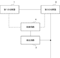
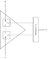
- FIG. 1 shows an outline of the configuration of the path switching device of the present embodiment.
- the path switching device according to the present embodiment includes a first switch 1, a second switch 2, a detection circuit 3, and a control circuit 4.
- the first switch 1 is an example of a first switch.
- the second switch 2 is an example of a second switching unit.
- the detection circuit 3 is an example of a detection unit.
- the control circuit 4 is an example of a control unit.
- the first switch 1 switches the connection between the optical fiber of the first submarine cable and the optical fiber of the third submarine cable connected to a predetermined optical path or an optical add / drop multiplexer by a first switch. Switch by.
- the second switch 2 is configured to connect an optical fiber of the second submarine cable to a predetermined optical path connected to the first switch or an optical fiber of the third submarine cable connected to the optical add / drop multiplexer. The connection to either of them is switched by the second switch.
- the detection circuit 3 detects the state of an optical signal input from the optical add / drop multiplexer to the second switch via the optical fiber of the third submarine cable.
- the control circuit 4 operates based on electric power supplied via a power supply line of the first submarine cable or the second submarine cable, and controls switching of the first switch and the second switch. Further, the control circuit 4 controls the first switch and the second switch based on the detection state of the optical signal by the detection circuit 3.
- the path switching device detects the state of the optical signal input from the optical add / drop multiplexer to the second switch, and controls the first switch and the second switch by the control circuit 4. Further, the control circuit 4 controls the switch by operating based on the power supplied through the power supply line of the first submarine cable or the second submarine cable. Therefore, the path switching device according to the present embodiment operates even when power is not supplied from the optical add / drop multiplexer, and can perform switch switching according to the state of the optical signal. As a result, when the path switching device of the present embodiment is used, communication can be continued by an operation according to the failure occurrence state.
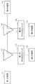
- FIG. 2 shows the outline of the configuration of the optical submarine cable system of the present embodiment.
- the optical submarine cable system according to the present embodiment is configured as an optical communication network that transmits wavelength-multiplexed optical signals.
- the optical submarine cable system according to the present embodiment includes a branch unit and a ROADM (Reconfigurable Optical Add / Drop Multiplexer) unit, has a branch structure, and is configured as a network for performing communication between a plurality of terminal stations.
- ROADM Reconfigurable Optical Add / Drop Multiplexer
- the optical submarine cable system includes a first terminal station 11, a second terminal station 12, a third terminal station 13, a fourth terminal station 14, a first branch unit 15, A second branch unit 16, a first ROADM unit 17, and a second ROADM unit 18 are provided.
- the submarine cable between the first terminal station 11 and the fourth terminal station 14 forms a trunk line.
- a second terminal station 12 and a third terminal station 13 are connected to a branch line branched from the trunk line. That is, in the optical submarine cable system of the present embodiment, the first terminal station 11 and the fourth terminal station 14 function as trunk stations, and the second terminal station 12 and the third terminal station 13 function as branch stations. .
- Each terminal is installed on land. Further, each branch unit and each ROADM unit are installed as submarine equipment. The terminal station and the branch unit, the branch unit and the ROADM unit, and the ROADM unit and the terminal station are connected via submarine cables.
- the submarine cable is composed of an optical fiber and a feed line.
- the optical fiber has a plurality of cores and transmits an optical signal bidirectionally.
- the first terminal station 11, the second terminal station 12, the third terminal station 13, and the fourth terminal station 14 include an optical terminal device, a power supply device, and a monitoring device.
- the optical terminal device transmits and receives a wavelength multiplexed signal to and from another terminal via a submarine cable.
- the power supply device supplies power to each submarine device via a power supply line of the submarine cable.
- the monitoring device monitors a communication state of the optical signal in the transmission path.
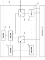
- FIG. 3 shows a configuration of the branch unit 20 used as the first branch unit 15 and the second branch unit 16.
- the branch unit 20 includes a control circuit 21, a drive circuit 22, a first optical switch 23, a second optical switch 24, an optical coupler 25, a photoelectric conversion unit 26, and a switching circuit 27.
- the control circuit 21 controls the drive circuit 22 to switch the optical switch.
- the control circuit 21 operates based on the power supplied through the power supply line of the trunk line.
- the drive circuit 22 switches between the first optical switch 23 and the second optical switch 24.
- the control circuit 21 and the drive circuit 22 are configured using a semiconductor device such as an FPGA (Field Programmable Gate Array).
- the control circuit 21 and the drive circuit 22 may be configured to execute each processing by executing a computer program on a CPU (Central Processing Unit).
- the first optical switch 23 and the second optical switch 24 switch the path of the optical signal.
- the first optical switch 23 connects a path connected to the optical fiber on the trunk station side to a path on either the second optical switch 24 side or the branch station side.
- the second optical switch 24 connects the path connected to the optical fiber on the trunk station side to either the first optical switch 23 side or the path on the branch station side.
- a switch using MEMS Micro Electro Mechanical Systems
- the functions of the first optical switch 23 and the second optical switch 24 of the present embodiment correspond to the first switching unit 1 and the second switching unit 2 of the first embodiment, respectively.
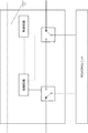
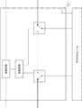
- FIGS. 4 and 5 are diagrams schematically showing the states of the optical switches and the paths connected thereto.
- trunk lines A and B are connected to each other by an optical switch. Therefore, the wavelength multiplexed signals input from the A side and the B side are output to the other side without passing through the ROADM unit. Therefore, the terminal stations connected to the A side and the B side cannot communicate with the terminal station connected to the C side. Further, the terminal station connected to the C side cannot communicate with another terminal station.
- the A and B sides of the trunk line and the C side of the branch line are connected by an optical switch. Therefore, the wavelength multiplexed signals input from the A side, the B side and the C side are input to the ROADM unit and are distributed to each path according to the wavelength setting.
- the optical coupler 25 branches an optical signal input from the trunk station side.
- the optical coupler 25 outputs the branched optical signal to the second optical switch 24 and the photoelectric conversion unit 26.
- the branching ratio in the optical coupler 25 is set such that the optical power of the optical signal output to the second optical switch 24 is large enough to maintain the transmission quality of the optical signal.
- the photoelectric conversion unit 26 converts an optical signal input from the optical coupler 25 into an electric signal.
- the photoelectric conversion unit 26 is configured using a photodiode.
- the photoelectric conversion unit 26 outputs an electric signal converted from the optical signal to the switching circuit 27. Further, the functions of the optical coupler 25 and the photoelectric conversion unit 26 of the present embodiment correspond to the detection unit 3 of the first embodiment.
- the switching circuit 27 outputs a signal for switching the switch to the first optical switch 23 and the second optical switch 24 when no electric signal is input.
- the first optical switch 23 connects the path on the trunk station side to the path on the second optical switch 24 side.
- the second optical switch 24 connects to the path on the trunk station side and the path on the first optical switch 23 side.
- the functions of the control circuit 21, the drive circuit 22, and the switching circuit 27 of the present embodiment correspond to the control unit 4 of the first embodiment.
- the first optical switch 23 of the first branch unit 15 connects the path on the first terminal station 11 side to the path on the first ROADM unit 17 side.
- the second optical switch 24 of the first branch unit 15 connects the path on the second branch unit 16 side to the path on the first ROADM unit 17 side.
- the first optical switch 23 of the second branch unit 16 connects the path on the first branch unit 15 side to the path on the second ROADM unit 18 side.
- the second optical switch 24 of the second branch unit 16 connects the path on the fourth terminal station 14 side to the path on the second ROADM unit 18 side.
- the wavelength division multiplexed signal output from the first terminal station 11 is sent to the fourth terminal station 14.
- the wavelength multiplexed signal output from the first terminal station 11 is sent to the first ROADM unit 17 via the first branch unit 15.
- the first ROADM unit 17 separates the optical signal of the wavelength group to be sent to the second terminal station 12 from the wavelength multiplexed signal, Output. Further, the first ROADM unit 17 combines the optical signals transmitted to the third terminal station 13 and the fourth terminal station 14 from the optical signals transmitted from the second terminal station 12 with the wavelength multiplexed signal. Waves.
- the first ROADM unit 17 sends the wavelength multiplexed signal to the first branch unit 15.
- the first branch unit 15 sends the wavelength multiplexed signal to the second branch unit 16.
- the wavelength multiplexed signal input to the second branch unit 16 is sent to the second ROADM unit 18.
- the second ROADM unit 18 separates the optical signal of the wavelength group to be sent to the third terminal station 13 from the wavelength multiplexed signal, Output. Further, the second ROADM unit 18 multiplexes the optical signal transmitted to the fourth terminal station 14 from the optical signals transmitted from the third terminal station 13 into a wavelength multiplexed signal. When the optical signal sent from the third terminal station 13 is multiplexed with the wavelength multiplexed signal, the second ROADM unit 18 sends the wavelength multiplexed signal to the second branch unit 16.
- the wavelength division multiplexed signal input to the second branch unit 16 is sent to the fourth terminal station 14.
- the wavelength multiplexed signal is transmitted in the same way on the reverse route.
- the first ROADM unit 17 cannot receive power supply from the trunk line.
- the first ROADM unit 17 can operate based on power supplied from the second terminal 12 of the branch line.
- the wavelength division multiplexed signal branched by the optical coupler 25 is input to the photoelectric conversion unit 26. Therefore, switching of the switch element of the first branch unit 15 is not performed. Therefore, transmission / reception of the wavelength multiplex signal between the terminal stations is continued in the same manner as in the normal state.
- the wavelength multiplexed signal output from the first ROADM unit 17 is not input to the first branch unit 15. Therefore, no optical signal is sent from the optical coupler 25 to the photoelectric conversion unit 26.
- the switching circuit 27 outputs a signal requesting switching of a switch to the drive circuit 22 when the electric signal input from the photoelectric conversion unit 26 becomes equal to or less than the reference.
- the drive circuit 22 switches between the first optical switch 23 and the second optical switch 24.
- the drive circuit 22 controls the first optical switch 23 to connect the path on the first terminal 11 side to the path on the second optical switch 24 side.
- the drive circuit 22 controls the second optical switch 24 to connect the path on the fourth terminal station 14 side to the path on the first optical switch 23 side. At this time, the path on the fourth terminal station 14 side and the path on the first ROADM unit 17 side are disconnected.
- signals can be transmitted and received between the first terminal station 11, the third terminal station 13, and the fourth terminal station 14.
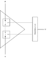
- FIG. 6 shows an example of the configuration of a branch unit when the control circuit receives power supply from the branch line side.
- the trunk line is designed to be connected when power is not supplied due to an abnormality in the branch-side power supply line.
- the state in which the trunk lines are connected to each other is initialized, and the switch is initialized when power is not supplied.
- the branch unit and the ROADM unit cannot communicate with each other, so that the branch station cannot communicate with another terminal station.
- FIG. 7 shows an example of the configuration of a branch unit when the control circuit receives power supply from the trunk side.
- the control circuit that operates with the power supplied from the trunk side operates normally, so that the switch is connected between the trunk side and the branch side.
- the terminal station on the trunk side and the terminal station on the branch side can continue communication.
- a communication fault occurs because the terminal station on the trunk side and the terminal station on the branch side are connected in a state where no fault is detected and no optical signal is transmitted. appear.
- the optical submarine cable system when the power supply from the ground of the branch unit to the point of failure disappears, if the communication of the optical signal is normally performed, the path from the branch unit to the ROADM unit is changed. The state of the switching optical switch is maintained. Since the control circuit of the branch unit according to the present embodiment is supplied with power from the trunk side, the state of the switch can be maintained even if a failure occurs on the branch side. Further, an optical signal input from the branch side is monitored, and switch control for disconnecting the branch side is performed only when the optical signal cannot be detected. Therefore, in the present embodiment, it is possible to avoid a state of trying to communicate with the branch side despite the occurrence of a failure, and to continue the communication on the trunk side normally.
- the branch unit of the optical submarine cable system according to the present embodiment controls the switch element by the electric power supplied through the feeder line on the trunk side. Therefore, even when an abnormality occurs in the branch-side power supply line, the state of the switch element can be maintained. Therefore, when an abnormality occurs only in the power supply line and the optical signal can be transmitted normally through the optical fiber, the communication can be normally continued.
- the optical coupler monitors an optical signal input from the branch side. When the optical signal cannot be detected, a switch is switched to connect the trunk sides. Therefore, the optical submarine cable system of the present embodiment can continue communication on the trunk side even if an abnormality occurs on the branch side. As a result, the optical submarine cable system according to the present embodiment can continue communication by an operation according to the state of occurrence of the failure.
Landscapes
- Engineering & Computer Science (AREA)
- Computer Networks & Wireless Communication (AREA)
- Signal Processing (AREA)
- Physics & Mathematics (AREA)
- Electromagnetism (AREA)
- Optical Communication System (AREA)
Abstract
障害の発生状態に応じた動作により通信を継続することができる経路切替装置を提供するため、経路切替装置を、第1の切替器1と、第2の切替器2と、検出回路3と、制御回路4を備える構成とする。第1の切替器1は、第1の海底ケーブルと、所定の光経路または光分岐挿入装置と接続されている第3の海底ケーブルのいずれかとの接続を第1のスイッチで切り替える。第2の切替器2は、第2の海底ケーブルと、第1のスイッチと接続している所定の光経路または光分岐挿入装置と接続されている第3の海底ケーブルのいずれかとの接続を第2のスイッチで切り替える。検出回路3は、第3の海底ケーブルを介して入力される光信号の状態を検出する。制御回路4は、第1の海底ケーブルまたは第2の海底ケーブルを介して供給される電力を元にスイッチの切り替えを制御する。制御回路4は、光信号の検出状態に基づいてスイッチを制御する。
Description
本発明は、光海底ケーブルシステムに関するものであり、特に、海底機器に関するものである。
光海底ケーブルシステムでは、波長多重化された光信号の一部をブランチ局側に分岐する装置として、ブランチユニットとROADM(Reconfigurable Optical Add / Drop Multiplexer)ユニットを接続する構成が用いられることが多い。ブランチユニットとROADMユニットは、海底機器の筐体の大きさの制限から一体構成にできないため、ブランチユニットの近傍に、海底ケーブルを介して接続されたROADMユニットを配置する構成が用いられることがある。
ブランチユニットやROADMユニット等の海底機器は、陸上の端局から海底ケーブルの給電線を介して供給される電力を元に動作する。そのため、光海底ケーブルシステムにおいて通信を継続的に行うためには、各海底機器に安定して電力を供給する必要がある。しかし、海底に敷設されている海底ケーブルは損傷することもあり、損傷した海底ケーブルを介した電力の供給が止まる恐れがある。海底ケーブルの損傷等が発生した場合にも、障害の発生状態に応じて各海底機器の動作を継続させることが望ましい。そのため、海底ケーブルの損傷等が発生した場合に海底機器の動作を継続させる技術の開発が行われている。そのような、海底ケーブルの損傷等が発生した場合に、障害の発生状態に応じて海底機器の動作を継続させる技術としては、例えば、特許文献1のような技術が開示されている。
特許文献1は、ブランチ局側とトランク局側から海底機器に電力を供給する給電システムに関するものである。特許文献1の給電システムは、トランク局側の給電機能に障害が生じた際に、ブランチ局側から給電を行い、障害が生じていない海底機器の動作をさせることで通信を継続させている。
しかしながら、特許文献1の技術は次のような点で十分ではない。トランク側とブランチ側を接続する部分に、ブランチユニットとROADMユニットの接続に海底ケーブルを用いたような構成では、ブランチユニットとROADMユニット間の海底ケーブルにも障害が起こり得る。そのような場合に、ROADMユニット等が動作可能にも関わらず、スイッチ素子の初期化等により、トランク局とブランチ局間の通信が行えなくなる恐れがある。そのため、特許文献1の技術は、海底ケーブルの損傷等が発生した場合に、障害の発生状態に応じて海底機器を適切に動作させて通信を継続するための技術としては十分ではない。
本発明は、上記の課題を解決するため、海底ケーブルに障害が発生した際に、障害の発生状態に応じた動作によって通信を継続することができる経路切替装置を提供することを目的としている。
上記の課題を解決するため、本発明の経路切替装置は、第1の切替手段と、第2の切替手段と、検出手段と、制御手段を備えている。第1の切替手段は、第1の海底ケーブルの光ファイバと、所定の光経路または光分岐挿入装置と接続されている第3の海底ケーブルの光ファイバのいずれかとの接続を第1のスイッチによって切り替える。第2の切替手段は、第2の海底ケーブルの光ファイバと、第1のスイッチと接続している所定の光経路または光分岐挿入装置と接続されている第3の海底ケーブルの光ファイバのいずれかとの接続を第2のスイッチによって切り替える。検出手段は、光分岐挿入装置から第3の海底ケーブルの光ファイバを介して第2のスイッチに入力される光信号の状態を検出する。制御手段は、第1の海底ケーブルまたは第2の海底ケーブルの給電線を介して供給される電力を元に動作し、第1のスイッチおよび第2のスイッチの切り替えを制御する。また、制御手段は、検出手段3による光信号の検出状態に基づいて、第1のスイッチおよび第2のスイッチを制御する。
本発明の経路切替方法は、第1の海底ケーブルの光ファイバと、所定の光経路または光分岐挿入装置と接続されている第3の海底ケーブルの光ファイバのいずれかとの接続を切り替える第1のスイッチとを接続する。本発明の経路切替方法は、第2の海底ケーブルの光ファイバと、第1のスイッチと接続している所定の光経路または光分岐挿入装置と接続されている第3の海底ケーブルの光ファイバのいずれかとの接続を切り替える第2のスイッチとを接続する。本発明の経路切替方法は、光分岐挿入装置から第3の海底ケーブルの光ファイバを介して第2のスイッチに入力される光信号の状態を検出する。本発明の経路切替方法は、光信号の検出状態に基づいて、第1の海底ケーブルまたは第2の海底ケーブルの給電線を介して供給される電力を元に、第1のスイッチおよび第2のスイッチを切り替える。
本発明によると、障害の発生状態に応じた動作によって通信を継続することができる。
(第1の実施形態)
本発明の第1の実施形態について図を参照して詳細に説明する。図1は、本実施形態の経路切替装置の構成の概要を示したものである。本実施形態の経路切替装置は、第1の切替器1と、第2の切替器2と、検出回路3と、制御回路4を備えている。第1の切替器1は、第1の切替手段の一例である。第2の切替器2は、第2の切替手段の一例である。検出回路3は、検出手段の一例である。制御回路4は、制御手段の一例である。第1の切替器1は、第1の海底ケーブルの光ファイバと、所定の光経路または光分岐挿入装置と接続されている第3の海底ケーブルの光ファイバのいずれかとの接続を第1のスイッチによって切り替える。第2の切替器2は、第2の海底ケーブルの光ファイバと、第1のスイッチと接続している所定の光経路または光分岐挿入装置と接続されている第3の海底ケーブルの光ファイバのいずれかとの接続を第2のスイッチによって切り替える。検出回路3は、光分岐挿入装置から第3の海底ケーブルの光ファイバを介して第2のスイッチに入力される光信号の状態を検出する。制御回路4は、第1の海底ケーブルまたは第2の海底ケーブルの給電線を介して供給される電力を元に動作し、第1のスイッチおよび第2のスイッチの切り替えを制御する。また、制御回路4は、検出回路3による光信号の検出状態に基づいて、第1のスイッチおよび第2のスイッチを制御する。
本発明の第1の実施形態について図を参照して詳細に説明する。図1は、本実施形態の経路切替装置の構成の概要を示したものである。本実施形態の経路切替装置は、第1の切替器1と、第2の切替器2と、検出回路3と、制御回路4を備えている。第1の切替器1は、第1の切替手段の一例である。第2の切替器2は、第2の切替手段の一例である。検出回路3は、検出手段の一例である。制御回路4は、制御手段の一例である。第1の切替器1は、第1の海底ケーブルの光ファイバと、所定の光経路または光分岐挿入装置と接続されている第3の海底ケーブルの光ファイバのいずれかとの接続を第1のスイッチによって切り替える。第2の切替器2は、第2の海底ケーブルの光ファイバと、第1のスイッチと接続している所定の光経路または光分岐挿入装置と接続されている第3の海底ケーブルの光ファイバのいずれかとの接続を第2のスイッチによって切り替える。検出回路3は、光分岐挿入装置から第3の海底ケーブルの光ファイバを介して第2のスイッチに入力される光信号の状態を検出する。制御回路4は、第1の海底ケーブルまたは第2の海底ケーブルの給電線を介して供給される電力を元に動作し、第1のスイッチおよび第2のスイッチの切り替えを制御する。また、制御回路4は、検出回路3による光信号の検出状態に基づいて、第1のスイッチおよび第2のスイッチを制御する。
本実施形態の経路切替装置は、光分岐挿入装置から第2のスイッチに入力される光信号の状態を検出し、制御回路4によって第1のスイッチおよび第2のスイッチの制御を行っている。また、制御回路4は、第1の海底ケーブルまたは第2の海底ケーブルの給電線を介して供給される電力を元に動作してスイッチの制御を行っている。よって、本実施形態の経路切替装置は、光分岐挿入装置側からの電力の供給がない状態でも動作し、光信号の状態に応じたスイッチの切り替えを行うことができる。その結果、本実施形態の経路切替装置を用いると、障害の発生状態に応じた動作によって通信を継続することができる。
(第2の実施形態)
本発明の第2の実施形態について図を参照して詳細に説明する。図2は、本実施形態の光海底ケーブルシステムの構成の概要を示したものである。本実施形態の光海底ケーブルシステムは、波長多重化された光信号を伝送する光通信ネットワークとして構成されている。本実施形態の光海底ケーブルシステムは、ブランチユニットとROADM(Reconfigurable Optical Add / Drop Multiplexer)ユニットを備え、分岐構造を有し、複数の端局間で通信を行うネットワークとして構成されている。
本発明の第2の実施形態について図を参照して詳細に説明する。図2は、本実施形態の光海底ケーブルシステムの構成の概要を示したものである。本実施形態の光海底ケーブルシステムは、波長多重化された光信号を伝送する光通信ネットワークとして構成されている。本実施形態の光海底ケーブルシステムは、ブランチユニットとROADM(Reconfigurable Optical Add / Drop Multiplexer)ユニットを備え、分岐構造を有し、複数の端局間で通信を行うネットワークとして構成されている。
本実施形態の光海底ケーブルシステムは、第1の端局11と、第2の端局12と、第3の端局13と、第4の端局14と、第1のブランチユニット15と、第2のブランチユニット16と、第1のROADMユニット17と、第2のROADMユニット18を備えている。
本実施形態の光海底ケーブルシステムは、第1の端局11と、第4の端局14間の海底ケーブルがトランクラインを形成している。また、トランクラインから分岐したブランチラインに第2の端局12と、第3の端局13が接続されている。すなわち、本実施形態の光海底ケーブルシステムでは、第1の端局11および第4の端局14がトランク局、第2の端局12および第3の端局13がブランチ局としての機能を有する。
各端局は、陸上に設置されている。また、各ブランチユニットおよび各ROADMユニットは、海底機器として設置されている。端局とブランチユニットの間、ブランチユニットとROADMユニットの間、および、ROADMユニットと端局の間は、それぞれ海底ケーブルを介して接続されている。海底ケーブルは、光ファイバおよび給電線によって構成されている。光ファイバは、複数のコアを有し、双方向に光信号を伝送する。
第1の端局11、第2の端局12、第3の端局13および第4の端局14は、光端局装置、給電装置および監視装置を備えている。光端局装置は、海底ケーブルを介して他の端局との間で波長多重信号の送受信を行う。給電装置は、海底ケーブルの給電線を介して各海底機器に電源を供給する。監視装置は、伝送路における光信号の通信状態を監視する。
第1のブランチユニット15および第2のブランチユニット16の構成について説明する。図3は、第1のブランチユニット15および第2のブランチユニット16として用いられるブランチユニット20の構成を示したものである。
ブランチユニット20は、制御回路21と、駆動回路22と、第1の光スイッチ23と、第2の光スイッチ24と、光カプラ25と、光電変換部26と、切替回路27を備えている。
制御回路21は、駆動回路22を制御して光スイッチの切り替えを行う。制御回路21は、トランクラインの給電線を介して供給される電源を元に動作する。
駆動回路22は、第1の光スイッチ23および第2の光スイッチ24の切り替えを行う。制御回路21および駆動回路22は、FPGA(Field Programmable Gate Array)等の半導体装置を用いて構成されている。制御回路21および駆動回路22は、CPU(Central Processing Unit)上でコンピュータプログラムを実行することで各処理を行う構成であってもよい。
第1の光スイッチ23および第2の光スイッチ24は、光信号の経路を切り替える。第1の光スイッチ23は、トランク局側の光ファイバと接続されている経路を、第2の光スイッチ24側またはブランチ局側のいずれかの経路と接続する。また、第2の光スイッチ24は、トランク局側の光ファイバと接続されている経路を、第1の光スイッチ23側またはブランチ局側のいずれかの経路と接続する。光スイッチには、例えば、MEMS(Micro Electro Mechanical Systems)を用いたスイッチが用いられる。また、本実施形態の第1の光スイッチ23および第2の光スイッチ24の機能は、第1の実施形態の第1の切替手段1および第2の切替手段2にそれぞれ相当する。
図4および図5は光スイッチの状態と接続されている経路を模式的に示した図である。図4は、互いにトランクラインのAとBが光スイッチによって接続されている。そのため、A側およびB側から入力された波長多重信号は、ROADMユニットを介さずにもう一方の側に出力されている。そのため、A側およびB側に接続されている端局は、C側に接続されている端局とは通信を行うことはできない。また、C側に接続されている端局は、他の端局と通信を行うことはできない。
図5は、トランクラインのA側、B側とブランチラインのC側が光スイッチによって接続されている。そのため、A側、B側およびC側から入力された波長多重信号は、ROADMユニットに入力され、波長設定に応じて各経路に振り分けられる。
光カプラ25は、トランク局側から入力される光信号を分岐する。光カプラ25は、分岐した光信号を第2の光スイッチ24および光電変換部26に出力する。光カプラ25における分岐比は、第2の光スイッチ24側に出力される光信号の光パワーが、光信号の伝送品質を維持する上で十分な大きさとなるように設定されている。
光電変換部26は、光カプラ25から入力される光信号を電気信号に変換する。光電変換部26は、フォトダイオードを用いて構成されている。光電変換部26は、光信号から変換した電気信号を切替回路27に出力する。また、本実施形態の光カプラ25および光電変換部26の機能は、第1の実施形態の検出手段3に相当する。
切替回路27は、電気信号が入力されないとき、第1の光スイッチ23および第2の光スイッチ24にスイッチを切り替える信号を出力する。スイッチを切り替える信号が入力されたとき、第1の光スイッチ23は、トランク局側の経路と、第2の光スイッチ24側の経路を接続する。また、スイッチを切り替える信号が入力されたとき、第2の光スイッチ24は、トランク局側の経路と、第1の光スイッチ23側の経路と接続する。また、本実施形態の制御回路21、駆動回路22および切替回路27の機能は、第1の実施形態の制御手段4に相当する。
本実施形態の光海底ケーブルシステムの動作について説明する。始めに、正常時の動作について説明する。
正常時、第1のブランチユニット15の第1の光スイッチ23は、第1の端局11側の経路と第1のROADMユニット17側の経路とを接続している。また、第1のブランチユニット15の第2の光スイッチ24は、第2のブランチユニット16側の経路と第1のROADMユニット17側の経路とを接続している。
正常時、第2のブランチユニット16の第1の光スイッチ23は、第1のブランチユニット15側の経路と第2のROADMユニット18側の経路とを接続している。また、第2のブランチユニット16の第2の光スイッチ24は、第4の端局14側の経路と第2のROADMユニット18側の経路とを接続している。
第1の端局11から出力された波長多重信号が第4の端局14に送られる場合を例に説明する。第1の端局11から出力された波長多重信号は、第1のブランチユニット15を介して、第1のROADMユニット17に送られる。波長多重信号が入力されると、第1のROADMユニット17は、波長多重信号のうち第2の端局12に送る波長群の光信号を分離し、第2の端局12側の光ファイバに出力する。また、第1のROADMユニット17は、第2の端局12から送られてくる光信号のうち、第3の端局13および第4の端局14に送られる光信号を波長多重信号に合波する。第2の端局12から送られてくる光信号を波長多重信号に合波すると、第1のROADMユニット17は、波長多重信号を第1のブランチユニット15に送る。
第1のROADMユニット17から波長多重信号が入力されると、第1のブランチユニット15は、波長多重信号を第2のブランチユニット16に送る。
第2のブランチユニット16に入力された波長多重信号は、第2のROADMユニット18に送られる。
波長多重信号が入力されると、第2のROADMユニット18は、波長多重信号のうち第3の端局13に送る波長群の光信号を分離し、第3の端局13側の光ファイバに出力する。また、第2のROADMユニット18は、第3の端局13から送られてくる光信号のうち、第4の端局14に送られる光信号を波長多重信号に合波する。第3の端局13から送られてくる光信号を波長多重信号に合波すると、第2のROADMユニット18は、波長多重信号を第2のブランチユニット16に送る。
第2のブランチユニット16に入力された波長多重信号は、第4の端局14に送られる。また、第4の端局14から第1の端局11に波長多重信号が送られる場合には、波長多重信号は、上記の逆の経路で同様に伝送される。
次に、ブランチユニットとROADMユニットの間の海底ケーブルに異常が生じた際の動作について説明する。第1のブランチユニット15と第1のROADMユニット17の間を接続する海底ケーブルに異常が生じた場合を例に説明する。始めに給電線のみに異常が生じた場合について説明する。
第1のブランチユニット15の給電線に異常が生じると、第1のROADMユニット17は、トランクラインからの電源の供給を受けられなくなる。第1のROADMユニット17は、ブランチラインの第2の端局12から供給される電源を元に動作することができる。また、このとき、光カプラ25において分岐された波長多重信号が光電変換部26に入力される。そのため、第1のブランチユニット15のスイッチ素子の切り替えは、行われない。よって、端局間の波長多重信号の送受信は、正常時と同じように継続される。
次に、光ファイバに異常が生じた場合を例に説明する。光ファイバに異常が生じると、第1のROADMユニット17から出力された波長多重信号は、第1のブランチユニット15に入力されない。よって、光カプラ25から光電変換部26に光信号が送られなくなる。切替回路27は、光電変換部26から入力される電気信号が基準以下になると、駆動回路22にスイッチの切り替えを要求する信号を出力する。スイッチの切り替えを要求する信号を受け取ると、駆動回路22は、第1の光スイッチ23および第2の光スイッチ24の切り替えを行う。駆動回路22は、第1の光スイッチ23を制御して第1の端局11側の経路と第2の光スイッチ24側の経路を接続する。このとき、第1の端局11側の経路と第1のROADMユニット17側の経路は、切断された状態となる。また、駆動回路22は、第2の光スイッチ24を制御し第4の端局14側の経路と第1の光スイッチ23側の経路を接続する。このとき、第4の端局14側の経路と第1のROADMユニット17側の経路は、切断された状態となる。
第1の光スイッチ23および第2の光スイッチ24が行われると、第1の端局11、第3の端局13および第4の端局14間での信号の送受信が可能になる。
図6は、制御回路がブランチライン側から電力の供給を受ける場合のブランチユニットの構成の例を示したものである。図6のような構成では、ブランチ側の給電線に異常が生じて電力が供給されないとき、トランクライン同士を接続するように設計される。図6のような構成では、トランクライン同士を接続する状態が初期設定とされ、電力が供給されないときスイッチは初期化される。初期化された際にブランチユニットとROADMユニットは通信を行うことができないので、ブランチ局は他の端局と通信を行うことができない。
図7は、制御回路がトランク側から電力の供給を受ける場合のブランチユニットの構成の例を示したものである。図7のような構成では、ブランチ側の給電線に障害が生じても、トランク側から供給される電力で動作する制御回路は、正常に動くため、スイッチをトランク側とブランチ側とが接続している状態で維持する。このとき、光ファイバが正常な場合には、トランク側の端局と、ブランチ側の端局は通信を継続することができる。一方で、光ファイバに障害が生じている場合には、障害が検知されずに光信号が伝送されない状態でトランク側の端局と、ブランチ側の端局が接続されているため通信の障害が発生する。
一方で、本実施形態の光海底ケーブルシステムは、ブランチユニットのアースから障害点までの給電がなくなった場合に、光信号の通信が正常にできていれば、ブランチユニットからROADMユニットへの経路を切り替える光スイッチの状態を維持している。本実施形態のブランチユニットの制御回路は、トランク側から電力の供給を受けているので、ブランチ側で障害が生じてもスイッチの状態を維持することができる。また、ブランチ側から入力される光信号を監視し、光信号を検出できないときにのみブランチ側を切り離すスイッチ制御を行っている。そのため、本実施形態では、障害が生じているにも関わらずブランチ側と通信を行おうとする状態を避け、トランク側での通信を正常に継続することができる。
本実施形態の光海底ケーブルシステムのブランチユニットは、トランク側の給電線を介して供給される電力によってスイッチ素子の制御を行っている。そのため、ブランチ側の給電線に異常が生じた際にもスイッチ素子の状態を維持することができる。そのため、給電線のみに異常が生じ、光ファイバで正常に光信号を伝送できる場合には、正常に通信を継続することができる。また、光カプラでブランチ側から入力される光信号を監視し、光信号を検出できないとき、スイッチを切り替えてトランク側どうしを接続している。そのため、本実施形態の光海底ケーブルシステムは、ブランチ側で異常が生じてもトランク側の通信を継続することができる。その結果、本実施形態の光海底ケーブルシステムは、障害の発生状態に応じた動作によって通信を継続することができる。
以上、上述した実施形態を模範的な例として本発明を説明した。しかしながら、本発明は、上述した実施形態には限定されない。即ち、本発明は、本発明のスコープ内において、当業者が理解し得る様々な態様を適用することができる。
この出願は、2018年9月10日に出願された日本出願特願2018-168969を基礎とする優先権を主張し、その開示の全てをここに取り込む。
1 第1の切替器
2 第2の切替器
3 検出回路
4 制御回路
11 第1の端局
12 第2の端局
13 第3の端局
14 第4の端局
15 第1のブランチユニット
16 第2のブランチユニット
17 第1のROADMユニット
18 第2のROADMユニット
20 ブランチユニット
21 制御回路
22 駆動回路
23 第1の光スイッチ
24 第2の光スイッチ
25 光カプラ
26 光電変換部
27 切替回路
2 第2の切替器
3 検出回路
4 制御回路
11 第1の端局
12 第2の端局
13 第3の端局
14 第4の端局
15 第1のブランチユニット
16 第2のブランチユニット
17 第1のROADMユニット
18 第2のROADMユニット
20 ブランチユニット
21 制御回路
22 駆動回路
23 第1の光スイッチ
24 第2の光スイッチ
25 光カプラ
26 光電変換部
27 切替回路
Claims (10)
- 第1の海底ケーブルの光ファイバと、所定の光経路または光分岐挿入装置と接続されている第3の海底ケーブルの光ファイバのいずれかとの接続を第1のスイッチによって切り替える第1の切替手段と、
第2の海底ケーブルの光ファイバと、前記第1のスイッチと接続している前記所定の光経路または前記光分岐挿入装置と接続されている前記第3の海底ケーブルの光ファイバのいずれかとの接続を第2のスイッチによって切り替える第2の切替手段と、
前記光分岐挿入装置から前記第3の海底ケーブルの光ファイバを介して前記第2のスイッチに入力される光信号の状態を検出する検出手段と、
前記第1の海底ケーブルまたは前記第2の海底ケーブルの給電線を介して供給される電力を元に動作し、前記第1のスイッチおよび前記第2のスイッチの切り替えを制御する制御手段と
を備え、
前記制御手段は、前記検出手段による前記光信号の検出状態に基づいて、前記第1のスイッチおよび前記第2のスイッチを制御することを特徴とする経路切替装置。 - 前記制御手段は、前記検出手段が前記光信号を検出しているとき、前記第1のスイッチが前記第1の海底ケーブルの光ファイバと、前記第3の海底ケーブルの光ファイバとを接続し、前記第2のスイッチが前記第2の海底ケーブルの光ファイバと、前記第3の海底ケーブルの光ファイバとを接続するように制御し、
前記検出手段が前記光信号を検出できないとき、前記第1の海底ケーブルの光ファイバと、前記第2の海底ケーブルの光ファイバが前記所定の光経路を介して接続されるように前記第1のスイッチおよび前記第2のスイッチを制御することを特徴とする請求項1記載の経路切替装置。 - 前記第3の海底ケーブルの光ファイバを介して入力される波長多重信号を分岐する分岐手段と、
前記分岐手段によって分岐された波長多重信号を電気信号に変換する光電変換手段と
をさらに備え、
前記検出手段は、前記光電変換手段から出力される前記電気信号を基に前記光信号の状態を検出することを特徴とする請求項1または2に記載の経路切替装置。 - 請求項1から3いずれかに記載の経路切替装置と、
前記第3の海底ケーブルを介して前記経路切替装置と接続された光分岐挿入装置と
を備えることを特徴とする海底分岐装置。 - 前記経路切替装置は、前記第1の海底ケーブルおよび前記第2の海底ケーブルを介してトランクラインに接続され、前記第3の海底ケーブルを介してブランチラインに接続されていることを特徴とする請求項4に記載の海底分岐装置。
- 請求項4または5いずれかに記載の海底分岐装置と、
前記第1の海底ケーブルを介して波長多重信号の送受信および電力の供給を行う第1の端局と、
前記第3の海底ケーブルを介して波長多重信号の送受信および電力の供給を行う第2の端局と
を備えることを特徴とする光海底ケーブルシステム。 - 前記海底分岐装置は、前記第1の端局から送信された波長多重信号のうち第1の波長群の信号を分岐して前記第2の端局に送信し、前記第2の端局から入力される第2の波長群の信号を前記波長多重信号に挿入して出力することを特徴とする請求項6に記載の光海底ケーブルシステム。
- 第1の海底ケーブルの光ファイバと、所定の光経路または光分岐挿入装置と接続されている第3の海底ケーブルの光ファイバのいずれかとの接続を切り替える第1のスイッチとを接続し、
第2の海底ケーブルの光ファイバと、前記第1のスイッチと接続している前記所定の光経路または前記光分岐挿入装置と接続されている前記第3の海底ケーブルの光ファイバのいずれかとの接続を切り替える第2のスイッチとを接続し、
前記光分岐挿入装置から前記第3の海底ケーブルの光ファイバを介して前記第2のスイッチに入力される光信号の状態を検出し、
前記光信号の検出状態に基づいて、前記第1の海底ケーブルまたは前記第2の海底ケーブルの給電線を介して供給される電力を元に、前記第1のスイッチおよび前記第2のスイッチを切り替えることを特徴とする経路切替方法。 - 前記光信号を検出しているとき、前記第1のスイッチが前記第1の海底ケーブルの光ファイバと、前記第3の海底ケーブルの光ファイバとを接続し、前記第2のスイッチが前記第2の海底ケーブルの光ファイバと、前記第3の海底ケーブルの光ファイバとを接続し、
前記光信号を検出できないとき、前記第1の海底ケーブルの光ファイバと、前記第2の海底ケーブルの光ファイバが前記所定の光経路を介して接続されるように前記第1のスイッチおよび前記第2のスイッチを切り替えることを特徴とする請求項8に記載の経路切替方法。 - 前記第3の海底ケーブルの光ファイバを介して入力される波長多重信号を分岐し、
分岐した前記波長多重信号を電気信号に変換し、
変換した前記電気信号を基に前記光信号の状態を検出することを特徴とする請求項8または9に記載の経路切替方法。
Priority Applications (4)
| Application Number | Priority Date | Filing Date | Title |
|---|---|---|---|
| EP19859430.1A EP3852285A4 (en) | 2018-09-10 | 2019-09-06 | PATH SWITCHING APPARATUS AND PATH SWITCHING METHOD |
| US17/274,305 US20210336694A1 (en) | 2018-09-10 | 2019-09-06 | Path switching apparatus and path switching method |
| JP2020545991A JPWO2020054614A1 (ja) | 2018-09-10 | 2019-09-06 | 経路切替装置および経路切替方法 |
| CN201980058729.5A CN112740575A (zh) | 2018-09-10 | 2019-09-06 | 路径切换设备及路径切换方法 |
Applications Claiming Priority (2)
| Application Number | Priority Date | Filing Date | Title |
|---|---|---|---|
| JP2018-168969 | 2018-09-10 | ||
| JP2018168969 | 2018-09-10 |
Publications (1)
| Publication Number | Publication Date |
|---|---|
| WO2020054614A1 true WO2020054614A1 (ja) | 2020-03-19 |
Family
ID=69778326
Family Applications (1)
| Application Number | Title | Priority Date | Filing Date |
|---|---|---|---|
| PCT/JP2019/035191 Ceased WO2020054614A1 (ja) | 2018-09-10 | 2019-09-06 | 経路切替装置および経路切替方法 |
Country Status (5)
| Country | Link |
|---|---|
| US (1) | US20210336694A1 (ja) |
| EP (1) | EP3852285A4 (ja) |
| JP (1) | JPWO2020054614A1 (ja) |
| CN (1) | CN112740575A (ja) |
| WO (1) | WO2020054614A1 (ja) |
Cited By (2)
| Publication number | Priority date | Publication date | Assignee | Title |
|---|---|---|---|---|
| CN113473269A (zh) * | 2020-03-31 | 2021-10-01 | 萨伯康姆有限责任公司 | 三条海底光纤光缆之间的成对路由 |
| WO2022055910A1 (en) * | 2020-09-11 | 2022-03-17 | Nec Laboratories America, Inc. | Three-way branching unit switch module having small footprint |
Families Citing this family (1)
| Publication number | Priority date | Publication date | Assignee | Title |
|---|---|---|---|---|
| US12340791B1 (en) * | 2021-06-10 | 2025-06-24 | Amazon Technologies, Inc. | Enhanced voice-based presentation of user sentiment |
Citations (7)
| Publication number | Priority date | Publication date | Assignee | Title |
|---|---|---|---|---|
| WO2012144585A1 (ja) * | 2011-04-20 | 2012-10-26 | 日本電気株式会社 | Oadm機能をもつ分岐装置及び波長多重光ネットワークシステム並びにその方法 |
| WO2016092806A1 (ja) * | 2014-12-10 | 2016-06-16 | 日本電気株式会社 | 給電路分岐装置及び給電路分岐方法 |
| WO2016147610A1 (ja) * | 2015-03-16 | 2016-09-22 | 日本電気株式会社 | 拡張分岐装置及び拡張分岐装置の制御方法 |
| WO2016181642A1 (ja) | 2015-05-12 | 2016-11-17 | 日本電気株式会社 | 給電路切替装置、給電路切替システムおよび給電路切替方法 |
| JP2017508331A (ja) * | 2013-12-25 | 2017-03-23 | ▲ホア▼▲ウェイ▼海洋網絡有限公司 | 光挿入分岐マルチプレクサ分岐ユニット |
| WO2017141855A1 (ja) * | 2016-02-17 | 2017-08-24 | 日本電気株式会社 | 接地回路及び接地方法 |
| JP2018168969A (ja) | 2017-03-30 | 2018-11-01 | リンナイ株式会社 | 三方弁 |
Family Cites Families (4)
| Publication number | Priority date | Publication date | Assignee | Title |
|---|---|---|---|---|
| EP2770654A4 (en) * | 2012-06-15 | 2014-12-17 | Huawei Marine Networks Co Ltd | EMERGENCY RECOVERY METHOD, DEVICE AND SYSTEM FOR AN OPTICAL COMMUNICATION SYSTEM |
| EP2738959B1 (en) * | 2012-11-30 | 2017-08-09 | Alcatel Lucent | System and method for providing underwater communication data |
| CN104518828B (zh) * | 2013-09-30 | 2017-06-06 | 华为海洋网络有限公司 | 海底分支单元及海缆终端设备 |
| EP3176616A1 (en) * | 2015-12-04 | 2017-06-07 | Xtera Communications Limited | Optical branching unit |
-
2019
- 2019-09-06 EP EP19859430.1A patent/EP3852285A4/en not_active Withdrawn
- 2019-09-06 US US17/274,305 patent/US20210336694A1/en not_active Abandoned
- 2019-09-06 CN CN201980058729.5A patent/CN112740575A/zh active Pending
- 2019-09-06 JP JP2020545991A patent/JPWO2020054614A1/ja active Pending
- 2019-09-06 WO PCT/JP2019/035191 patent/WO2020054614A1/ja not_active Ceased
Patent Citations (7)
| Publication number | Priority date | Publication date | Assignee | Title |
|---|---|---|---|---|
| WO2012144585A1 (ja) * | 2011-04-20 | 2012-10-26 | 日本電気株式会社 | Oadm機能をもつ分岐装置及び波長多重光ネットワークシステム並びにその方法 |
| JP2017508331A (ja) * | 2013-12-25 | 2017-03-23 | ▲ホア▼▲ウェイ▼海洋網絡有限公司 | 光挿入分岐マルチプレクサ分岐ユニット |
| WO2016092806A1 (ja) * | 2014-12-10 | 2016-06-16 | 日本電気株式会社 | 給電路分岐装置及び給電路分岐方法 |
| WO2016147610A1 (ja) * | 2015-03-16 | 2016-09-22 | 日本電気株式会社 | 拡張分岐装置及び拡張分岐装置の制御方法 |
| WO2016181642A1 (ja) | 2015-05-12 | 2016-11-17 | 日本電気株式会社 | 給電路切替装置、給電路切替システムおよび給電路切替方法 |
| WO2017141855A1 (ja) * | 2016-02-17 | 2017-08-24 | 日本電気株式会社 | 接地回路及び接地方法 |
| JP2018168969A (ja) | 2017-03-30 | 2018-11-01 | リンナイ株式会社 | 三方弁 |
Non-Patent Citations (1)
| Title |
|---|
| See also references of EP3852285A4 * |
Cited By (2)
| Publication number | Priority date | Publication date | Assignee | Title |
|---|---|---|---|---|
| CN113473269A (zh) * | 2020-03-31 | 2021-10-01 | 萨伯康姆有限责任公司 | 三条海底光纤光缆之间的成对路由 |
| WO2022055910A1 (en) * | 2020-09-11 | 2022-03-17 | Nec Laboratories America, Inc. | Three-way branching unit switch module having small footprint |
Also Published As
| Publication number | Publication date |
|---|---|
| US20210336694A1 (en) | 2021-10-28 |
| EP3852285A1 (en) | 2021-07-21 |
| JPWO2020054614A1 (ja) | 2021-08-30 |
| EP3852285A4 (en) | 2021-11-17 |
| CN112740575A (zh) | 2021-04-30 |
Similar Documents
| Publication | Publication Date | Title |
|---|---|---|
| CN106664151B (zh) | 光通信设备、光通信系统以及光通信方法 | |
| US10349153B2 (en) | Optical multiplexing and demultiplexing device, and method of controlling optical multiplexing and demultiplexing device | |
| US10484086B2 (en) | Optical branching unit | |
| CN107534461B (zh) | 供电路径切换装置、供电路径切换系统和供电路径切换方法 | |
| CN111295851B (zh) | 海底光学通信系统和海底分支装置 | |
| JP7024858B2 (ja) | 海底分岐装置、光海底ケーブルシステム及び光通信方法 | |
| WO2020054614A1 (ja) | 経路切替装置および経路切替方法 | |
| JP7597297B2 (ja) | 海底電力ルーティングデバイスおよび海底ケーブル分岐アーキテクチャ | |
| JP4376263B2 (ja) | 光波長多重システム | |
| JP4973557B2 (ja) | ポイントtoマルチポイント光通信システム | |
| US9872090B2 (en) | Wavelength redundancy device and wavelength redundancy method | |
| CN113841345B (zh) | 汇接设备和海底线缆系统 | |
| JP5365721B2 (ja) | 局回線終端装置 | |
| WO2014010151A1 (ja) | 波長分割多重通信装置及び光ネットワークシステム | |
| US12439187B2 (en) | Optical branching/coupling device and method for controlling same | |
| US20250105939A1 (en) | Optical splitting/coupling device, optical submarine cable system, and optical splitting/coupling method | |
| JP3123510B2 (ja) | 光adm装置の監視方法並びにこれを用いた光adm装置 | |
| JPS6362424A (ja) | 伝送方式 | |
| CN114223152A (zh) | 海底设备、海底设备监视方法和光学通信系统 | |
| HK1136637A1 (en) | Hybrid switch for optical networks | |
| HK1136637B (zh) | 用於光網絡的混合開關 |
Legal Events
| Date | Code | Title | Description |
|---|---|---|---|
| 121 | Ep: the epo has been informed by wipo that ep was designated in this application |
Ref document number: 19859430 Country of ref document: EP Kind code of ref document: A1 |
|
| ENP | Entry into the national phase |
Ref document number: 2020545991 Country of ref document: JP Kind code of ref document: A |
|
| NENP | Non-entry into the national phase |
Ref country code: DE |
|
| ENP | Entry into the national phase |
Ref document number: 2019859430 Country of ref document: EP Effective date: 20210412 |