WO2020054650A1 - インホイールモータ駆動装置 - Google Patents
インホイールモータ駆動装置 Download PDFInfo
- Publication number
- WO2020054650A1 WO2020054650A1 PCT/JP2019/035329 JP2019035329W WO2020054650A1 WO 2020054650 A1 WO2020054650 A1 WO 2020054650A1 JP 2019035329 W JP2019035329 W JP 2019035329W WO 2020054650 A1 WO2020054650 A1 WO 2020054650A1
- Authority
- WO
- WIPO (PCT)
- Prior art keywords
- gear
- input
- output
- side intermediate
- wheel
- Prior art date
- Legal status (The legal status is an assumption and is not a legal conclusion. Google has not performed a legal analysis and makes no representation as to the accuracy of the status listed.)
- Ceased
Links
Images

Classifications
-
- H—ELECTRICITY
- H02—GENERATION; CONVERSION OR DISTRIBUTION OF ELECTRIC POWER
- H02K—DYNAMO-ELECTRIC MACHINES
- H02K7/00—Arrangements for handling mechanical energy structurally associated with dynamo-electric machines, e.g. structural association with mechanical driving motors or auxiliary dynamo-electric machines
- H02K7/14—Structural association with mechanical loads, e.g. with hand-held machine tools or fans
-
- B—PERFORMING OPERATIONS; TRANSPORTING
- B60—VEHICLES IN GENERAL
- B60K—ARRANGEMENT OR MOUNTING OF PROPULSION UNITS OR OF TRANSMISSIONS IN VEHICLES; ARRANGEMENT OR MOUNTING OF PLURAL DIVERSE PRIME-MOVERS IN VEHICLES; AUXILIARY DRIVES FOR VEHICLES; INSTRUMENTATION OR DASHBOARDS FOR VEHICLES; ARRANGEMENTS IN CONNECTION WITH COOLING, AIR INTAKE, GAS EXHAUST OR FUEL SUPPLY OF PROPULSION UNITS IN VEHICLES
- B60K7/00—Disposition of motor in, or adjacent to, traction wheel
- B60K7/0007—Disposition of motor in, or adjacent to, traction wheel the motor being electric
-
- B—PERFORMING OPERATIONS; TRANSPORTING
- B60—VEHICLES IN GENERAL
- B60K—ARRANGEMENT OR MOUNTING OF PROPULSION UNITS OR OF TRANSMISSIONS IN VEHICLES; ARRANGEMENT OR MOUNTING OF PLURAL DIVERSE PRIME-MOVERS IN VEHICLES; AUXILIARY DRIVES FOR VEHICLES; INSTRUMENTATION OR DASHBOARDS FOR VEHICLES; ARRANGEMENTS IN CONNECTION WITH COOLING, AIR INTAKE, GAS EXHAUST OR FUEL SUPPLY OF PROPULSION UNITS IN VEHICLES
- B60K17/00—Arrangement or mounting of transmissions in vehicles
- B60K17/04—Arrangement or mounting of transmissions in vehicles characterised by arrangement, location or kind of gearing
- B60K17/043—Transmission unit disposed in on near the vehicle wheel, or between the differential gear unit and the wheel
-
- F—MECHANICAL ENGINEERING; LIGHTING; HEATING; WEAPONS; BLASTING
- F16—ENGINEERING ELEMENTS AND UNITS; GENERAL MEASURES FOR PRODUCING AND MAINTAINING EFFECTIVE FUNCTIONING OF MACHINES OR INSTALLATIONS; THERMAL INSULATION IN GENERAL
- F16H—GEARING
- F16H1/00—Toothed gearings for conveying rotary motion
- F16H1/02—Toothed gearings for conveying rotary motion without gears having orbital motion
- F16H1/20—Toothed gearings for conveying rotary motion without gears having orbital motion involving more than two intermeshing members
-
- F—MECHANICAL ENGINEERING; LIGHTING; HEATING; WEAPONS; BLASTING
- F16—ENGINEERING ELEMENTS AND UNITS; GENERAL MEASURES FOR PRODUCING AND MAINTAINING EFFECTIVE FUNCTIONING OF MACHINES OR INSTALLATIONS; THERMAL INSULATION IN GENERAL
- F16H—GEARING
- F16H55/00—Elements with teeth or friction surfaces for conveying motion; Worms, pulleys or sheaves for gearing mechanisms
- F16H55/02—Toothed members; Worms
- F16H55/08—Profiling
-
- F—MECHANICAL ENGINEERING; LIGHTING; HEATING; WEAPONS; BLASTING
- F16—ENGINEERING ELEMENTS AND UNITS; GENERAL MEASURES FOR PRODUCING AND MAINTAINING EFFECTIVE FUNCTIONING OF MACHINES OR INSTALLATIONS; THERMAL INSULATION IN GENERAL
- F16H—GEARING
- F16H55/00—Elements with teeth or friction surfaces for conveying motion; Worms, pulleys or sheaves for gearing mechanisms
- F16H55/02—Toothed members; Worms
- F16H55/14—Construction providing resilience or vibration-damping
- F16H55/16—Construction providing resilience or vibration-damping relating to teeth only
-
- F—MECHANICAL ENGINEERING; LIGHTING; HEATING; WEAPONS; BLASTING
- F16—ENGINEERING ELEMENTS AND UNITS; GENERAL MEASURES FOR PRODUCING AND MAINTAINING EFFECTIVE FUNCTIONING OF MACHINES OR INSTALLATIONS; THERMAL INSULATION IN GENERAL
- F16H—GEARING
- F16H57/00—General details of gearing
- F16H57/0006—Vibration-damping or noise reducing means specially adapted for gearings
-
- H—ELECTRICITY
- H02—GENERATION; CONVERSION OR DISTRIBUTION OF ELECTRIC POWER
- H02K—DYNAMO-ELECTRIC MACHINES
- H02K21/00—Synchronous motors having permanent magnets; Synchronous generators having permanent magnets
- H02K21/12—Synchronous motors having permanent magnets; Synchronous generators having permanent magnets with stationary armatures and rotating magnets
- H02K21/14—Synchronous motors having permanent magnets; Synchronous generators having permanent magnets with stationary armatures and rotating magnets with magnets rotating within the armatures
-
- H—ELECTRICITY
- H02—GENERATION; CONVERSION OR DISTRIBUTION OF ELECTRIC POWER
- H02K—DYNAMO-ELECTRIC MACHINES
- H02K7/00—Arrangements for handling mechanical energy structurally associated with dynamo-electric machines, e.g. structural association with mechanical driving motors or auxiliary dynamo-electric machines
- H02K7/10—Structural association with clutches, brakes, gears, pulleys or mechanical starters
- H02K7/116—Structural association with clutches, brakes, gears, pulleys or mechanical starters with gears
-
- B—PERFORMING OPERATIONS; TRANSPORTING
- B60—VEHICLES IN GENERAL
- B60K—ARRANGEMENT OR MOUNTING OF PROPULSION UNITS OR OF TRANSMISSIONS IN VEHICLES; ARRANGEMENT OR MOUNTING OF PLURAL DIVERSE PRIME-MOVERS IN VEHICLES; AUXILIARY DRIVES FOR VEHICLES; INSTRUMENTATION OR DASHBOARDS FOR VEHICLES; ARRANGEMENTS IN CONNECTION WITH COOLING, AIR INTAKE, GAS EXHAUST OR FUEL SUPPLY OF PROPULSION UNITS IN VEHICLES
- B60K7/00—Disposition of motor in, or adjacent to, traction wheel
- B60K2007/0038—Disposition of motor in, or adjacent to, traction wheel the motor moving together with the wheel axle
-
- B—PERFORMING OPERATIONS; TRANSPORTING
- B60—VEHICLES IN GENERAL
- B60K—ARRANGEMENT OR MOUNTING OF PROPULSION UNITS OR OF TRANSMISSIONS IN VEHICLES; ARRANGEMENT OR MOUNTING OF PLURAL DIVERSE PRIME-MOVERS IN VEHICLES; AUXILIARY DRIVES FOR VEHICLES; INSTRUMENTATION OR DASHBOARDS FOR VEHICLES; ARRANGEMENTS IN CONNECTION WITH COOLING, AIR INTAKE, GAS EXHAUST OR FUEL SUPPLY OF PROPULSION UNITS IN VEHICLES
- B60K7/00—Disposition of motor in, or adjacent to, traction wheel
- B60K2007/0061—Disposition of motor in, or adjacent to, traction wheel the motor axle being parallel to the wheel axle
-
- H—ELECTRICITY
- H02—GENERATION; CONVERSION OR DISTRIBUTION OF ELECTRIC POWER
- H02K—DYNAMO-ELECTRIC MACHINES
- H02K2213/00—Specific aspects, not otherwise provided for and not covered by codes H02K2201/00 - H02K2211/00
- H02K2213/03—Machines characterised by numerical values, ranges, mathematical expressions or similar information
-
- Y—GENERAL TAGGING OF NEW TECHNOLOGICAL DEVELOPMENTS; GENERAL TAGGING OF CROSS-SECTIONAL TECHNOLOGIES SPANNING OVER SEVERAL SECTIONS OF THE IPC; TECHNICAL SUBJECTS COVERED BY FORMER USPC CROSS-REFERENCE ART COLLECTIONS [XRACs] AND DIGESTS
- Y02—TECHNOLOGIES OR APPLICATIONS FOR MITIGATION OR ADAPTATION AGAINST CLIMATE CHANGE
- Y02T—CLIMATE CHANGE MITIGATION TECHNOLOGIES RELATED TO TRANSPORTATION
- Y02T10/00—Road transport of goods or passengers
- Y02T10/60—Other road transportation technologies with climate change mitigation effect
- Y02T10/64—Electric machine technologies in electromobility
Definitions
- the present invention relates to an in-wheel motor drive device that is arranged in an inner space area of a wheel and drives the wheel.
- an in-wheel motor driving device mounted in a wheel of a wheel is known.
- miniaturization and weight reduction are important issues because an increase in weight leads to an increase in unsprung load of a vehicle, which deteriorates running stability and NVH characteristics (noise, vibration, and harshness). is there.
- NVH characteristics noise, vibration, and harshness
- a motor alone is used to generate torque required for driving a vehicle, a large and heavy motor is required. Therefore, in the in-wheel motor drive device, by increasing the torque of the motor by using a speed reduction mechanism, a sufficient torque can be obtained even with a small motor, so that the size and weight of the motor are reduced.
- Japanese Patent Application Laid-Open Publication No. H11-163873 discloses an input shaft coaxially connected to a motor rotation shaft and having an input gear, and coaxially connected to an inner ring of a wheel hub bearing to output.
- a three-axis parallel shaft gear reduction mechanism including an output shaft having gears, a first intermediate gear meshing with the input gear, and an intermediate shaft having a second intermediate gear meshing with the output gear is disclosed.
- a helical gear is used as a gear constituting the speed reduction mechanism.
- Helical gears are superior to spur gears in that the number of simultaneously meshing teeth is increased and the tooth contact is dispersed, so that noise is quiet and torque fluctuation is small.
- the transmission error of meshing between gears is not limited to an in-wheel motor drive device, and is also applied to a drive device such as a so-called on-board type electric vehicle drive device provided with an electric motor on a vehicle body and a transmission mounted on a gasoline engine vehicle. Can occur as well.
- these driving devices are generally mounted on the vehicle body via a vibration isolating member such as a rubber bush, so that the vibration generated from the driving device is hardly transmitted to the vehicle body.
- the in-wheel motor drive device is mounted on wheels, vibration generated by the in-wheel motor drive device is easily transmitted to the vehicle body via a suspension or the like.
- an object of the present invention to provide an in-wheel motor drive device that can reduce the transmission error of meshing engagement between gears, realize low vibration, and ensure durability and miniaturization.
- the present invention provides an in-wheel motor drive device including an electric motor unit, a wheel bearing unit, and a speed reducer unit that transmits the rotation of the electric motor unit to the wheel bearing unit at a reduced speed.
- the reduction gear unit rotates integrally with the rotation shaft of the electric motor unit, and has an input shaft having an input gear, an output shaft having an output gear that rotates integrally with the rotation shaft of the wheel bearing unit, and an input gear.
- An input gear, an output gear, an input-side intermediate gear, and an output-side parallel gear reduction mechanism having three or more axes including an input-side intermediate gear that meshes with an output gear and an intermediate shaft that has an output-side intermediate gear that meshes with the output gear.
- the intermediate gear is a helical gear, and the output gear and the output-side intermediate gear are composed of larger modules than the input gear and the input-side intermediate gear, and the input gear and the output gear are more than the output gear and the output-side intermediate gear.
- Input side intermediate teeth But it consists of a large twist angle, than the input gear and the input-side intermediate gear, output gear and the output-side intermediate gear, characterized in that it is composed of a large effective tooth height.
- the method of reducing the size of the module can reduce the transmission error of meshing, but has a concern that the durability is reduced because the teeth are reduced.
- a large load acts on the second-stage gear (output gear and output-side intermediate gear) whose rotation is reduced more than that of the first-stage gear (input gear and input-side intermediate gear). It is necessary to increase the strength. Therefore, by making the second stage gear larger than the first stage gear as in the present invention, the durability of the second stage gear can be ensured.
- the first stage gear has a smaller load acting than the second stage gear, it is possible to reduce the size of the module preferentially and reduce the mesh transmission error.
- the method of increasing the torsion angle can reduce the meshing transmission error, but also increases the axial component of the load acting on the tooth surface. It is not preferable from the viewpoint of durability to make the torsion angle of the gear larger than that of the gear at the stage. Therefore, it is possible to avoid a large axial load from acting on the second-stage gear by setting the first-stage gear to a larger torsion angle than the second-stage gear as in the present invention. it can. On the other hand, since the first stage gear has a smaller load acting than the second stage gear, it is possible to preferentially increase the torsion angle and reduce the mesh transmission error.
- the method of increasing the effective tooth height can reduce the transmission error of meshing, but tends to make the tooth tip thinner, so there is a concern that the durability is reduced.
- increasing the effective tooth length in particular, makes the tooth tip narrower. Therefore, from the viewpoint of durability, the effective tooth height of the first-stage gear must be increased. Is not preferred. Therefore, as in the present invention, the second stage gear is preferentially made to have a larger effective tooth height than the first stage gear, so that the durability of the first stage gear is ensured and the second stage gear is secured. The transmission error of meshing of the gears can be reduced.
- the transmission error of the meshing is ensured while ensuring the durability. It is possible to reduce. Also, such adjustments of the module, the torsion angle, and the effective tooth length element do not affect the axial dimension of the gear, so that changing these elements also increases the axial dimension. Absent. Therefore, the size of the in-wheel motor driving device can be reduced.
- the front meshing pressure angle it is preferable to make the front meshing pressure angle smaller than that in the first stage gear in order to reduce the thinning of the tooth tip caused by increasing the effective tooth height. This makes it possible to alleviate the taper of the tooth tip of the second stage gear and improve the durability of the gear. Further, by reducing the front meshing pressure angle, the meshing transmission error of the second gear can be reduced.
- FIG. 3 is a vertical cross-sectional view of the in-wheel motor driving device when viewed along a line PP in FIG. 2.
- FIG. 2 is a cross-sectional view of the in-wheel motor driving device when viewed from the line QQ in FIG. 1. It is a figure which shows the gear by which a module differs. It is a figure which shows and compares gears with different helix angles. It is a figure which shows gears with different effective tooth heights in comparison. It is a top view showing the schematic structure of the electric vehicle carrying the in-wheel motor drive.
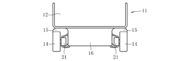
- FIG. 7 is a rear sectional view showing the electric vehicle of FIG. 6.
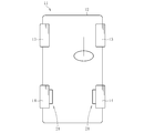
- FIG. 6 is a schematic plan view of the electric vehicle 11 on which the in-wheel motor drive device 21 is mounted
- FIG. 7 is a schematic sectional view of the electric vehicle 11 as viewed from the rear.
- the electric vehicle 11 includes a chassis 12, a front wheel 13 as a steering wheel, a rear wheel 14 as a driving wheel, and an in-wheel motor driving device 21 that transmits driving force to the rear wheel 14.
- the rear wheel 14 is housed inside a wheel housing 15 of the chassis 12 and is fixed to a lower portion of the chassis 12 via a suspension 16.
- the suspension device 16 supports the rear wheel 14 with a suspension arm extending left and right, and also absorbs vibration received by the rear wheel 14 from the ground by a strut including a coil spring and a shock absorber to suppress the vibration of the chassis 12.
- a stabilizer is provided at a connection portion between the left and right suspension arms to suppress a tilt of the vehicle body during turning or the like.
- the suspension device 16 is of an independent suspension type in which the left and right wheels are moved up and down independently in order to improve the ability to follow the unevenness of the road surface and efficiently transmit the driving force of the rear wheel 14 to the road surface.
- the electric vehicle 11 is provided with the in-wheel motor drive device 21 for driving the right and left rear wheels 14 inside the wheel housing 15, thereby eliminating the need to provide a motor, a drive shaft, a differential gear mechanism, and the like on the chassis 12. Therefore, there is an advantage that a large cabin space can be secured and the rotation of the left and right rear wheels 14 can be controlled.
- the overall configuration of the in-wheel motor drive device 21 will be described with reference to FIGS.
- the side (left side in FIG. 1) that is closer to the outside in the vehicle width direction is called the outboard side, and the side closer to the center (see FIG. 1). 1 is called the inboard side.
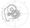
- FIG. 1 is a longitudinal sectional view of the in-wheel motor drive device taken along line PP of FIG. 2, and FIG. 2 is a cross-sectional view of the in-wheel motor drive device taken along line QQ of FIG. FIG.
- the in-wheel motor drive device 21 includes an electric motor unit A that generates a driving force, a speed reducer unit B that reduces the speed of rotation of the electric motor unit A, and outputs a signal. And a wheel bearing portion C for transmitting the output to the rear wheel 14 as a drive wheel.
- the electric motor section A, the speed reducer section B, and the wheel bearing section C are housed in the casing 22 respectively.
- the casing 22 may have an integral structure as shown in FIG. 1 or may have a dividable structure.
- the electric motor portion A includes a stator 23 fixed to the casing 22, a rotor 24 arranged to face the stator 23 radially inward with a gap, and a rotor 24 arranged radially inward of the rotor 24 and integrated with the rotor 24. It comprises a radial gap type electric motor 26 having a rotating motor rotating shaft 25.
- the motor rotation shaft 25 can rotate at a high speed of about ten thousandths of a minute.
- the stator 23 is configured by winding a coil around a magnetic core, and the rotor 24 is configured by a permanent magnet or the like.
- the electric motor unit A may be an axial gap type.
- the motor rotating shaft 25 has one end in the axial direction (the left side in FIG. 1) with the rolling bearing 40 and the other end in the axial direction (the right side in FIG. 1) with the rolling bearing 41 with respect to the casing 22. Each is rotatably supported.
- the reduction gear unit B is constituted by a three-shaft, two-stage parallel shaft gear reduction mechanism 39 having an input shaft 27, an intermediate shaft 28, and an output shaft 29 arranged in parallel with each other.
- the input shaft 27 is provided with an input gear 30, and the output shaft 29 is provided with an output gear 35.
- the intermediate shaft 28 is provided with an input-side intermediate gear 31 that meshes with the input gear 30 and an output-side intermediate gear 32 that meshes with the output gear 35.
- the input shaft 27 is rotatably supported by the casing 22 by two rolling bearings 42 and 43 provided on both sides of the input gear 30 in the axial direction.
- the intermediate shaft 28 is rotatably supported on the casing 22 by the two rolling bearings 44 and 45 in a state where the input side intermediate gear 31 is arranged on the inboard side and the output side intermediate gear 32 is arranged on the outboard side. Have been.
- the output shaft 29 is rotatably supported by the casing 22 by two rolling bearings 46 and 47 provided on both sides of the output gear 35 in the axial direction.
- these rolling bearings 40 to 47 it is preferable to use a bearing capable of receiving both a radial load and a thrust load, for example, a deep groove ball bearing.
- the rolling bearing 44 on the inboard side is on the outboard side (the output side intermediate gear 32 side).
- the rolling bearing 44 on the inboard side is on the outboard side (the output side intermediate gear 32 side).
- the large-diameter rolling bearing 44 is disposed in the inner-side concave portion 33 provided in the input-side intermediate gear 31.
- the two rolling bearings 46 and 47 for supporting the output shaft 29 are opposite to the rolling bearings 44 and 45 for supporting the intermediate shaft 28, and the rolling bearing 47 on the outboard side is more suitable for the rolling on the inboard side.
- the inner diameter and the outer diameter are larger than those of the bearing 46.
- the large-diameter rolling bearing 47 is disposed in the inner-side concave portion 34 provided on the output gear 35.
- the input shaft 27 is connected to the motor rotation shaft 25 so as to be integrally rotatable by spline fitting (including serration fitting).
- the output shaft 29 is integrally and rotatably connected to a hub wheel 60 constituting a rotation shaft of the wheel bearing portion C by spline fitting (including serration fitting).
- the wheel bearing portion C is composed of an inner ring rotating type wheel bearing 50.
- the wheel bearing 50 is a double-row angular ball bearing mainly including an inner member 61 including a hub wheel 60 and an inner ring 52, an outer ring 53, a plurality of balls 56, and a retainer (not shown).
- An inner raceway surface 54 is formed on each of the outer circumferences of the hub wheel 60 and the inner race 52, and a double-row outer raceway surface 55 is formed on the inner circumference of the outer race 53 in correspondence with each inner raceway surface 54. .
- a ball 56 is arranged between the inner raceway surface 54 and the outer raceway surface 55 facing each other so as to roll.
- a flange portion 60a for mounting a wheel is formed on the outer periphery of the hub wheel 60 on the outboard side.
- a brake disk and a wheel are mounted on the wheel mounting flange portion 60a.
- the inner ring 52 is fitted to the small-diameter stepped portion on the inboard side of the hub wheel 60, and the caulked portion 60 b of the hub wheel 60 is pressed against the inner ring 52.
- the caulked portion 60b is formed by caulking the inboard end of the hub wheel 60 after the inner ring 52 is fitted to the hub wheel 60.
- the inner ring 52 is positioned in the axial direction, and a preload is applied to the wheel bearing 50.
- the outer ring 53 is fastened and fixed to the casing 22 via the attachment 72 with the bolt 71.
- the outer ring 53 is also fastened and fixed to a mounting portion 73 to a suspension device by bolts.
- the rotational motion of the motor rotation shaft 25 is reduced in two steps, so that the amplified torque can be transmitted to the rear wheel 14. It is possible to use a small electric motor.
- the electric motor can be downsized by using an electric motor that rotates at a high speed of about ten thousand thousands of rotations per minute. As a result, a compact in-wheel motor driving device can be realized, and an electric vehicle having excellent running stability and NVH characteristics while suppressing unsprung weight can be obtained.
- the reduction ratio between the input gear 30 and the input-side intermediate gear 31 and the reduction ratio between the output-side intermediate gear 32 and the output gear 35 are both 2.5 or more and 7 or less. Is set. Each reduction ratio between these gears is set to a value close to each other. For example, the ratio between the reduction ratios is 0.5 or more and 2 or less, preferably 0.8 or more and 1.2 or less.
- the respective axis centers O1, O2, and O3 of the input shaft 27, the intermediate shaft 28, and the output shaft 29 form a vertex of a triangle. Are located.
- the shaft centers O1, O2, and O3 of the shafts 27, 28, and 29 are arranged in a triangular shape, the size of the outer peripheral contour of the in-wheel motor drive device 21 is reduced. Thereby, the in-wheel motor drive device 21 can be mounted in the rear wheel 70 of the existing internal combustion engine (see FIG. 2).
- a helical gear (external car) is used for the input gear 30, the input-side intermediate gear 31, the output-side intermediate gear 32, and the output gear 35.
- Helical gears are more effective than spur gears in that the number of meshing teeth increases simultaneously and the tooth contact is dispersed, so that noise is quiet and torque fluctuation is small.
- meshing transmission errors occur due to various factors such as the shape and elastic deformation of the tooth surface, processing errors of the gear shaft, clearances and elastic deformation of the bearings supporting the gear shaft, etc. I do. Since the mesh transmission error causes vibration, it is an important issue to reduce the mesh transmission error, particularly in an in-wheel motor drive device in which vibration is easily transmitted to the vehicle body side as compared with other vehicle drive devices.
- the meshing ratio of the helical gear is represented by the total meshing ratio ( ⁇ ) which is the sum of the front meshing ratio ( ⁇ a) and the overlapping meshing ratio ( ⁇ b) as shown in the following equation (1). .
- the front mesh ratio ( ⁇ a) is a value obtained by dividing the mesh length on the action line in front of the gear by the normal pitch, and is expressed by the following equation (2).
- da1 is a small diameter gear tip circle diameter
- da2 is a large diameter gear tip circle diameter
- db1 is a small diameter gear base circle diameter
- db2 is a large diameter gear base circle diameter
- a is a center-to-center distance
- ⁇ ′t is a front meshing pressure angle
- mt is a front module.
- the overlap mesh ratio ( ⁇ b) is a value obtained by dividing the tooth width by the pitch in the tooth width direction, and is represented by the following equation (3).
- b is the tooth width
- ⁇ is the torsion angle
- mt is the front module.
- the following methods (a) to (c) can be used to increase the front meshing ratio ( ⁇ a).
- A) Reduce the size of the gear module. (Increase the number of teeth.)
- B) Reduce the front meshing pressure angle.
- C) Increase the effective tooth length that effectively acts on meshing. (Increase the tip circle diameter.)
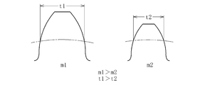
- the method of “reducing the size of the gear module” described in the above (a) and (d) will be examined. Since the module has a value obtained by dividing the pitch circle diameter of the gear by the number of teeth, the module can be made smaller by increasing the number of teeth with the same pitch circle diameter. However, as a matter of course, as the module becomes smaller, the size of the tooth alone also becomes smaller. As shown in FIG. 3, the teeth of the small module m2 have a smaller tooth thickness than the teeth of the large module m1 (t1> t2). Therefore, reducing the size of the module reduces the durability of the gear. Connect. Therefore, the module cannot be set to a value smaller than the value that satisfies the gear strength.
- the second-stage gears are more than the first-stage gears (the input gear 30 and the input-side intermediate gear 31).
- the second stage gear since a large load acts due to the reduction in rotation, it is necessary to obtain the strength of the gear in the second gear rather than in the first gear. In view of these circumstances, it is preferable to make the second stage gear larger than the first stage gear in order to ensure the durability of the gear.
- the method of “enlarging the torsion angle” described in the above (f) will be examined.
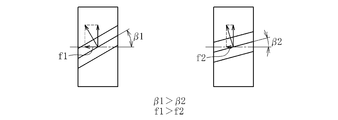
- the torsion angle is increased, the direction of the load applied to the tooth surface of the helical gear changes, so that the magnitude of the axial component of the load changes. That is, as shown in FIG. 4, when the torsion angle increases ( ⁇ 1> ⁇ 2), the axial component of the load applied to the tooth surface increases (f1> f2).
- the axial components of the load generated in each of the first-stage gear and the second-stage gear are received by each of the rolling bearings supporting the input shaft 27, the intermediate shaft 28, and the output shaft 29. Is increased, the axial load applied to the rolling bearing increases accordingly.
- the rolling bearing may be damaged.
- the rolling elements may ride on the end of the transfer surface excessively, which may cause early wear and breakage. Therefore, it can be said that increasing the torsion angle is more preferable for the first stage gear receiving a small load than for the second stage gear receiving a large load.
- the relationship between the first-stage gear and the second-stage gear is set as follows.
- the module considering that the second-stage gear receives a larger load than the first-stage gear, in order to ensure the durability of the second-stage gear, the module should be used as compared with the first-stage gear.
- the second stage gear is set as a large module. In other words, since the first-stage gear receives a smaller load than the second-stage gear, the module can be preferentially reduced in size. Therefore, by making the first stage gear smaller than the second stage gear, the front meshing ratio ( ⁇ a) and the overlap meshing ratio ( ⁇ b) can be preferentially increased.
- the first stage gear is set to a larger torsion angle than the second stage gear.
- ⁇ b overlapping mesh ratio
- the second stage gear having the larger module is less likely to cause a decrease in strength due to the thinner tooth tip than the first stage gear having the smaller module, so that the second stage gear has the first stage gear.
- the effective tooth length is set to be larger than that of the gear. This makes it possible to preferentially increase the front meshing ratio ( ⁇ a) of the second-stage gear while suppressing a decrease in the strength of the first-stage gear.
- the present embodiment by setting the module, the torsion angle, and the effective tooth height of the first-stage gear and the second-stage gear as described above, the durability of the gears and the rolling bearings is ensured. In addition, it is possible to effectively increase the front meshing ratio ( ⁇ a) and the overlap meshing ratio ( ⁇ b), and reduce the meshing transmission error. As a result, the vibration caused by the meshing transmission error can be suppressed, and the in-wheel motor drive device excellent in reducing the vibration can be provided. Further, since the adjustment of the module, the torsion angle, and the effective tooth length do not affect the axial dimension of the gear, the axial dimension does not increase due to the change of these elements, and It is also possible to reduce the size of the wheel motor driving device.
- the tooth tip becomes thinner (decrease in durability) due to the increase in the effective tooth height
- the gear tip of the second stage gear whose effective tooth height is increased becomes thinner.
- the front meshing pressure angle of the second-stage gear it is preferable to set the front meshing pressure angle of the second-stage gear to be smaller than that of the first-stage gear in order to alleviate the thinning of the tooth tip and improve the durability.
- the front meshing ratio ( ⁇ a) of the second stage gear is increased, and the meshing transmission error can be reduced. If there is no particular concern about the durability of the second stage gear, the first stage gear and the second stage gear may be set to the same front meshing pressure angle.
- the present invention is not limited to the above-described embodiments, and it is needless to say that the present invention can be embodied in various forms without departing from the gist of the present invention. It is.
- a three-axis two-stage reduction mechanism having three parallel shafts of the input shaft 27, the intermediate shaft 28, and the output shaft 29 has been described as an example.
- the present invention employs two or more intermediate shafts 28.
- the present invention is also applicable to a reduction mechanism having four or more axes.
Landscapes
- Engineering & Computer Science (AREA)
- General Engineering & Computer Science (AREA)
- Mechanical Engineering (AREA)
- Chemical & Material Sciences (AREA)
- Combustion & Propulsion (AREA)
- Transportation (AREA)
- Power Engineering (AREA)
- Gear Transmission (AREA)
- Connection Of Motors, Electrical Generators, Mechanical Devices, And The Like (AREA)
- Arrangement Or Mounting Of Propulsion Units For Vehicles (AREA)
Abstract
入力歯車30、出力歯車35、入力側中間歯車31及び出力側中間歯車32は、はすば歯車であって、入力歯車30及び入力側中間歯車31よりも、出力歯車35及び出力側中間歯車32が、大きいモジュールで構成され、出力歯車35及び出力側中間歯車32よりも、入力歯車30及び入力側中間歯車31が、大きいねじれ角で構成され、入力歯車30及び入力側中間歯車31よりも、出力歯車35及び出力側中間歯車32が、大きい有効歯丈で構成されている。
Description
本発明は、車輪の内空領域に配置されて当該車輪を駆動するインホイールモータ駆動装置に関する。
車輪を駆動する駆動装置として、車輪のホイール内に搭載されるインホイールモータ駆動装置が知られている。
インホイールモータ駆動装置においては、その重量の増加が走行安定性やNVH特性(騒音・振動・ハーシュネス)を悪化させる車両のばね下荷重の増加に繋がるため、小型化や軽量化は重要な課題である。一方で、モータ単体で車両の駆動に必要なトルクを発生させようとすると、大型で大重量のモータが必要となる。そのため、インホイールモータ駆動装置においては、減速機構を用いてモータのトルクを増大させることで、小型のモータでも十分なトルクが得られるようにして小型化及び軽量化が図られている。
このようなインホイールモータ駆動装置に用いられる減速機構として、下記特許文献1には、モータ回転軸と同軸に連結し入力歯車を有する入力軸と、車輪ハブ軸受部の内輪と同軸に連結し出力歯車を有する出力軸と、入力歯車と噛み合う第1中間歯車、及び、出力歯車と噛み合う第2中間歯車を有する中間軸とを備える、3軸の平行軸歯車減速機構が開示されている。
上記特許文献1に記載の減速機構においては、減速機構を構成する歯車に、はすば歯車を用いている。はすば歯車は、平歯車に比べて、同時に噛み合う歯数が増え、歯当たりが分散されるので音が静かであり、トルク変動が少ない点で優れている。
しかしながら、このような、はすば歯車を用いた減速機構においても、歯面の形状や弾性変形、歯車軸の加工誤差、歯車軸を支持している軸受の隙間や弾性変形などの種々の要因により、互いに噛み合う歯車同士の間で噛み合い伝達誤差(駆動歯車に対する被駆動歯車の相対的回転の遅れや進み)が発生する。噛み合い伝達誤差が大きくなると、これに伴って生じる振動や騒音も大きくなるため、乗り心地が悪化するだけでなく、振動によって部品が劣化したり破損したりする虞がある。
また、歯車同士の噛み合い伝達誤差は、インホイールモータ駆動装置に限らず、車体に電動モータを設けた所謂オンボードタイプの電動車両駆動装置や、ガソリンエンジン車に搭載されるトランスミッションなどの駆動装置においても同様に生じ得る。しかしながら、これらの駆動装置は、一般的にゴムブッシュなどの防振部材を介して車体に搭載されるため、駆動装置から発生した振動は車体側に伝達されにくい構成となっている。これに対して、インホイールモータ駆動装置は、車輪に取り付けられるため、インホイールモータ駆動装置で発生した振動はサスペンション等を介して車体側に伝達されやすい構成となっている。
以上のことから、特にインホイールモータ駆動装置においては、NVH特性を向上させるうえで、その振動を低減することが非常に重要であり、そのために、歯車同士の噛み合い伝達誤差を低減するための対策が求められる。
そこで、本発明は、歯車同士の噛み合い伝達誤差を低減して低振動化を実現できると共に、耐久性の確保及び小型化が可能なインホイールモータ駆動装置を提供することを目的とする。
上記課題を解決するため、本発明は、電動モータ部と、車輪用軸受部と、電動モータ部の回転を車輪用軸受部へ減速して伝達する減速機部とを備えたインホイールモータ駆動装置において、減速機部は、電動モータ部の回転軸と一体に回転し、入力歯車を有する入力軸と、車輪用軸受部の回転軸と一体に回転し、出力歯車を有する出力軸と、入力歯車と噛み合う入力側中間歯車、及び、出力歯車と噛み合う出力側中間歯車を有する中間軸とを備えた3軸以上の平行軸歯車減速機構であり、入力歯車、出力歯車、入力側中間歯車及び出力側中間歯車は、はすば歯車であって、入力歯車及び入力側中間歯車よりも、出力歯車及び出力側中間歯車が、大きいモジュールで構成され、出力歯車及び出力側中間歯車よりも、入力歯車及び入力側中間歯車が、大きいねじれ角で構成され、入力歯車及び入力側中間歯車よりも、出力歯車及び出力側中間歯車が、大きい有効歯丈で構成されていることを特徴とする。
はすば歯車同士の噛み合い伝達誤差を低減する方法としては、歯車のモジュールを小さくする方法、ねじれ角を大きくする方法、有効歯丈を大きくする方法がある。
まず、モジュールを小さくする方法は、噛み合い伝達誤差を低減できる一方で、歯が小さくなるため、耐久性が低下する懸念がある。ここで、1段目の歯車(入力歯車及び入力側中間歯車)よりも回転が減速される2段目の歯車(出力歯車及び出力側中間歯車)においては、大きな荷重が作用するため、歯車の強度を高くする必要がある。そのため、本発明のように、1段目の歯車よりも2段目の歯車を大きいモジュールとすることで、2段目の歯車の耐久性を確保することができる。一方、1段目の歯車は、2段目の歯車よりも作用する荷重が小さいので、優先的にモジュールを小さくして、噛み合い伝達誤差を低減することが可能である。
次に、ねじれ角を大きくする方法は、噛み合い伝達誤差を低減できる一方で、歯面に作用する荷重の軸方向成分が大きくなるため、特に大きな荷重が作用する2段目の歯車においては、1段目の歯車に比べて歯車のねじれ角を大きくすることは耐久性の観点から好ましくない。従って、本発明のように、2段目の歯車よりも1段目の歯車を大きいねじれ角とすることで、2段目の歯車に対して大きな軸方向荷重が作用するのを回避することができる。一方、1段目の歯車は、2段目の歯車よりも作用する荷重が小さいので、優先的にねじれ角を大きくして、噛み合い伝達誤差を低減することができる。
最後に、有効歯丈を大きくする方法は、噛み合い伝達誤差を低減できる一方で、歯先が細くなる傾向にあるので、耐久性が低下する懸念がある。上記のように、モジュールを小さくした1段目の歯車においては、有効歯丈を大きくすると、特に歯先が細くなるため、耐久性の観点から1段目の歯車の有効歯丈を大きくすることは好ましくない。そのため、本発明のように、1段目の歯車よりも2段目の歯車を優先的に大きい有効歯丈とすることで、1段目の歯車の耐久性を確保しつつ、2段目の歯車の噛み合い伝達誤差を低減することができる。
このように、本発明においては、1段目の歯車と2段目の歯車の、モジュール、ねじれ角、有効歯丈について上記の如く設定することで、耐久性を確保しつつ、噛み合い伝達誤差を低減することが可能である。また、このようなモジュール、ねじれ角、有効歯丈の各要素の調整は、歯車の軸方向寸法に影響を与えるものではないので、これらの要素を変更することに伴う軸方向寸法の増大も生じない。このため、インホイールモータ駆動装置の小型化も図ることが可能である。
さらに、2段目の歯車においては、有効歯丈を大きくすることに伴う歯先の細りを緩和するために、1段目の歯車よりも正面噛み合い圧力角を小さくすることが好ましい。これにより、2段目の歯車の歯先の細りを緩和し、歯車の耐久性を向上させることが可能である。また、正面噛み合い圧力角を小さくすることで、2段目の歯車の噛み合い伝達誤差を低減することもできる。
本発明によれば、耐久性の確保と小型化を図りつつ、歯車同士の噛み合い伝達誤差を低減して低振動化を実現することができる。
以下、添付の図面に基づき、本発明について説明する。なお、本発明を説明するための各図面において、同一の機能もしくは形状を有する部材や構成部品等の構成要素については、判別が可能な限り同一符号を付すことにより一度説明した後ではその説明を省略する。
図6は、インホイールモータ駆動装置21を搭載した電気自動車11の概略平面図、図7は、電気自動車11を後方から見た概略断面図である。
図6に示すように、電気自動車11は、シャシー12と、操舵輪としての前輪13と、駆動輪としての後輪14と、後輪14に駆動力を伝達するインホイールモータ駆動装置21とを装備する。図7に示すように、後輪14は、シャシー12のホイールハウジング15の内部に収容され、懸架装置(サスペンション)16を介してシャシー12の下部に固定されている。
懸架装置16は、左右に延びるサスペンションアームにより後輪14を支持すると共に、コイルスプリングとショックアブソーバとを含むストラットにより、後輪14が地面から受ける振動を吸収してシャシー12の振動を抑制する。左右のサスペンションアームの連結部分には、旋回時などの車体の傾きを抑制するスタビライザが設けられている。懸架装置16は、路面の凹凸に対する追従性を向上させ、後輪14の駆動力を効率よく路面に伝達するために、左右の車輪を独立して上下させる独立懸架式としている。
電気自動車11は、ホイールハウジング15の内部に、左右それぞれの後輪14を駆動するインホイールモータ駆動装置21を設けることによって、シャシー12上にモータ、ドライブシャフト及びデファレンシャルギヤ機構などを設ける必要がなくなるので、客室スペースを広く確保でき、かつ、左右の後輪14の回転をそれぞれ制御することができるという利点を有する。
この実施形態の特徴的な構成を説明する前にインホイールモータ駆動装置21の全体構成を図1及び図2に基づいて説明する。以下の説明では、インホイールモータ駆動装置21を車両に搭載した状態で、車両の車幅方向の外側寄りとなる側(図1において左側)をアウトボード側と称し、中央寄りとなる側(図1において右側)をインボード側と称する。
図1は、図2のP-P線で矢視したインホイールモータ駆動装置の縦断面図であり、図2は、図1のQ-Q線で矢視したインホイールモータ駆動装置の横断面図である。
図1に示すように、インホイールモータ駆動装置21は、駆動力を発生させる電動モータ部Aと、電動モータ部Aの回転を減速して出力する減速機部Bと、減速機部Bからの出力を駆動輪としての後輪14に伝達する車輪用軸受部Cとを備えている。電動モータ部A、減速機部B、及び車輪用軸受部Cは、それぞれケーシング22内に収容されている。ケーシング22は、図1に示すように一体構造とするほか、分割可能な構造にすることもできる。
電動モータ部Aは、ケーシング22に固定されたステータ23と、ステータ23の径方向内側に隙間をもって対向するように配置されたロータ24と、ロータ24の径方向内側に配置されてロータ24と一体回転するモータ回転軸25とを備えたラジアルギャップ型の電動モータ26で構成されている。モータ回転軸25は、毎分一万数千回転程度で高速回転可能である。ステータ23は磁性体コアにコイルを巻回することによって構成され、ロータ24は永久磁石等で構成されている。なお、電動モータ部Aは、アキシャルギャップ型であってもよい。
モータ回転軸25は、その軸方向一方側の端部(図1の左側)が転がり軸受40により、軸方向他方側の端部(図1の右側)が転がり軸受41により、ケーシング22に対してそれぞれ回転自在に支持されている。
減速機部Bは、互いに平行に配置された入力軸27と中間軸28と出力軸29とを備える3軸2段の平行軸歯車減速機構39で構成されている。入力軸27には入力歯車30が設けられ、出力軸29には出力歯車35が設けられている。また、中間軸28には、入力歯車30と噛み合う入力側中間歯車31と、出力歯車35と噛み合う出力側中間歯車32とが設けられている。
入力軸27は、入力歯車30の軸方向両側に設けられた2つの転がり軸受42,43によってケーシング22に対して回転自在に支持されている。中間軸28は、入力側中間歯車31をインボード側に配置し、出力側中間歯車32をアウトボード側に配置した状態で、2つの転がり軸受44,45によってケーシング22に対して回転自在に支持されている。また、出力軸29は、出力歯車35の軸方向両側に設けられた2つの転がり軸受46,47によってケーシング22に対して回転自在に支持されている。これらの転がり軸受40~47としては、ラジアル荷重とスラスト荷重の双方を受けることができる軸受、例えば深溝玉軸受を用いることが好ましい。
本実施形態では、中間軸28を支持する2つの転がり軸受44,45のうち、インボード側(入力側中間歯車31側)の転がり軸受44の方が、アウトボード側(出力側中間歯車32側)の転がり軸受45よりも大きい内径寸法及び外径寸法に形成されている。また、この大径の転がり軸受44は、入力側中間歯車31に設けられた内径側凹部33に配置されている。
出力軸29を支持する2つの転がり軸受46,47は、上記中間軸28を支持する転がり軸受44,45の関係とは逆に、アウトボード側の転がり軸受47の方が、インボード側の転がり軸受46よりも大きい内径寸法及び外径寸法に形成されている。また、この大径の転がり軸受47は、出力歯車35に設けられた内径側凹部34に配置されている。
入力軸27は、モータ回転軸25に対して、スプライン嵌合(セレーション嵌合を含む。)によって一体に回転可能に連結されている。一方、出力軸29は、車輪用軸受部Cの回転軸を構成するハブ輪60に対して、スプライン嵌合(セレーション嵌合も含む。)によって一体に回転可能に連結されている。
車輪用軸受部Cは、内輪回転タイプの車輪用軸受50で構成される。車輪用軸受50は、ハブ輪60と内輪52とからなる内方部材61と、外輪53と、複数の玉56及び保持器(図示省略)を主な構成とする複列アンギュラ玉軸受である。
ハブ輪60と内輪52との外周には、それぞれ内側軌道面54が形成され、外輪53の内周には、各内側軌道面54に対応して複列の外側軌道面55が形成されている。互いに対向する内側軌道面54と外側軌道面55との間には、玉56が転動可能に配置されている。
ハブ輪60のアウトボード側の外周には車輪取り付け用のフランジ部60aが形成されている。また、図示は省略するが、車輪取り付け用のフランジ部60aには、ブレーキディスク及びホイールが取り付けられる。一方、ハブ輪60のインボード側の小径段部には内輪52が嵌合され、内輪52に対してハブ輪60の加締め部60bが押し当てられている。加締め部60bは、ハブ輪60に対する内輪52の嵌合後にハブ輪60のインボード側端部が加締められることで形成される。加締め部60bが形成されることによって、内輪52の軸方向の位置決めを行うと共に車輪用軸受50に予圧が付与されている。
外輪53は、アタッチメント72を介してケーシング22にボルト71で締結固定されている。また、外輪53は、ボルトにより懸架装置への取り付け部73に対しても締結固定されている。
モータ回転軸25が回転すると、これと一体に入力軸27が回転し、その回転運動は互いに噛み合う入力歯車30と入力側中間歯車31との間で伝達されて中間軸28が回転する。そして、中間軸28の回転運動が互いに噛み合う出力側中間歯車32と出力歯車35との間で伝達され、出力軸29が回転する。このとき、回転運動は、入力歯車30からこれよりも歯数の多い入力側中間歯車31に伝達されることで減速され、さらに、出力側中間歯車32からこれよりも歯数の多い出力歯車35に伝達されることで減速される。
このように、本実施形態では、モータ回転軸25の回転運動が二段階に減速されることで、増幅されたトルクを後輪14へと伝達することができるので、低トルクかつ高回転型の小型電動モータを使用することが可能である。例えば、減速機部Bの減速比を11とした場合、毎分一万数千回転程度の高速回転の電動モータを使用することにより電動モータを小型化することができる。これにより、コンパクトなインホイールモータ駆動装置を実現することができ、ばね下重量を抑えて走行安定性及びNVH特性に優れた電気自動車を得ることができる。
本実施形態では、入力歯車30と入力側中間歯車31との間での減速比と、出力側中間歯車32と出力歯車35との間での減速比は、いずれも2.5以上7以下に設定されている。これらの歯車間での各減速比は、互いに近い値に設定され、例えば、減速比同士の比は0.5以上2以下、好ましくは0.8以上1.2以下であるのがよい。
また、本実施形態では、図2に示すように、軸方向から見て、入力軸27、中間軸28、出力軸29のそれぞれの軸中心O1,O2,O3が、三角形の頂点を成すように配置されている。このように、各軸27,28,29の軸中心O1,O2,O3が三角形状に配置されていることで、インホイールモータ駆動装置21の外周輪郭の小型化が図られている。これにより、既存の内燃機関の後輪のホイール70内にインホイールモータ駆動装置21を装着できるようにしている(図2参照)。
また、本実施形態では、入力歯車30、入力側中間歯車31、出力側中間歯車32及び出力歯車35に、はすば歯車(外画車)を用いている。はすば歯車は、平歯車に比べて、同時に噛合う歯数が増え、歯当たりが分散されるので音が静かで、トルク変動が少ない点で有効である。
しかしながら、はずば歯車を用いたとしても、歯面の形状や弾性変形、歯車軸の加工誤差、歯車軸を支持している軸受の隙間や弾性変形などの種々の要因により、噛み合い伝達誤差が発生する。噛み合い伝達誤差は振動の要因となるため、特に他の車両駆動装置に比べて車体側へ振動が伝達しやすいインホイールモータ駆動装置においては、噛み合い伝達誤差を低減することは重要な課題である。
噛み合い伝達誤差を小さくする方法として、歯車同士の噛み合い率を大きくする方法がある。噛み合い率を大きくすると、トルクによる歯車荷重が分散され、歯車同士の噛み合いにおけるトルク変動が小さくなるため、噛み合い伝達誤差を小さくすることができる。
ここで、はすば歯車における噛み合い率は、下記式(1)に示すように、正面噛み合い率(εa)と重なり噛み合い率(εb)との和である全噛み合い率(ε)によって表される。
正面噛み合い率(εa)は、歯車正面における作用線上の噛み合い長さを法線ピッチで除した値であり、下記式(2)により表される。式(2)中の、da1は小径歯車歯先円直径、da2は大径歯車歯先円直径、db1は小径歯車基礎円直径、db2は大径歯車基礎円直径、aは中心間距離、αtは正面圧力角、α´tは正面噛み合い圧力角、mtは正面モジュールである。

一方、重なり噛み合い率(εb)は、歯幅を歯幅方向のピッチで除した値であり、下記式(3)により表される。式(3)中の、bは歯幅、βはねじれ角、mtは正面モジュールである。

全噛み合い率(ε)を大きくするには、正面噛み合い率(εa)と重なり噛み合い率(εb)の少なくとも一方を大きくする必要がある。
正面噛み合い率(εa)を大きくする方法としては、次の(a)~(c)の方法が挙げられる。
(a)歯車のモジュールを小さくする。(歯数を多くする。)
(b)正面噛み合い圧力角を小さくする。
(c)噛み合いに有効に作用する有効歯丈を大きくする。(歯先円直径を大きくする。)
(a)歯車のモジュールを小さくする。(歯数を多くする。)
(b)正面噛み合い圧力角を小さくする。
(c)噛み合いに有効に作用する有効歯丈を大きくする。(歯先円直径を大きくする。)
一方、重なり噛み合い率(εb)を大きくする方法としては、次の(d)~(f)の方法が挙げられる。
(d)歯車のモジュールを小さくする。(歯数を多くする。)
(e)噛み合いに有効に作用する有効歯幅を大きくする。
(f)ねじれ角を大きくする。
(d)歯車のモジュールを小さくする。(歯数を多くする。)
(e)噛み合いに有効に作用する有効歯幅を大きくする。
(f)ねじれ角を大きくする。
以上の(a)~(f)に挙げられる方法を採用することで、正面噛み合い率(εa)及び重なり噛み合い率(εb)を大きくし、噛み合い伝達誤差を小さくすることが可能である。ただし、(a)~(f)に示される各要素は、歯車における噛み合い率のほか、歯車のサイズや強度、歯車に作用する荷重などにも影響を及ぼすため、インホイールモータ駆動装置における耐久性や小型化及び軽量化の観点も踏まえて検討する必要がある。
まず、上記(a)及び(d)に挙げられる「歯車のモジュールを小さくする」方法について検討する。モジュールは歯車のピッチ円直径を歯数で除した値であるので、同じピッチ円直径で歯数を多くすることによりモジュールを小さくすることができる。しかし、当然ながらモジュールが小さくなると、歯単体の大きさも小さくなる。図3に示すように、小さいモジュールm2の歯は、大きいモジュールm1の歯に比べて歯厚が小さくなるので(t1>t2)、モジュールを小さくすることは、歯車の耐久性が低下することに繋がる。従って、歯車の強度を満足する値よりも小さな値のモジュールに設定することはできない。特に、本実施形態のような3軸2段の減速機構においては、1段目の歯車(入力歯車30及び入力側中間歯車31)よりも2段目の歯車(出力歯車35及び出力側中間歯車32)において、回転が減速されることにより大きな荷重が作用するため、1段目の歯車よりも2段目の歯車において歯車の強度が得られるようにする必要がある。これらの事情を踏まえると、歯車の耐久性を確保するため、1段目の歯車よりも2段目の歯車を大きいモジュールとすることが好ましい。
また、モジュールを小さくすることに伴う耐久性低下を補填するため、上記(e)に挙げられる「有効歯幅を大きくする」方法を採用することも考えられる。有効歯幅を大きくすれば、歯車に作用する荷重を分散させることができるので、耐久性を向上させることができる。しかしながら、有効歯幅を大きくすると、歯車の軸方向寸法が大きくなってしまう。従って、「有効歯幅を大きくする」方法は、インホイールモータ駆動装置の小型化の観点からは採用し難い。
次に、上記(f)に挙げられる「ねじれ角を大きくする」方法について検討する。ねじれ角を大きくすると、はすば歯車の歯面が受ける荷重の方向が変化するため、荷重の軸方向成分の大きさが変化する。すなわち、図4に示すように、ねじれ角が大きくなると(β1>β2)、歯面が受ける荷重の軸方向成分が大きくなる(f1>f2)。本実施形態では、1段目の歯車と2段目の歯車のそれぞれにおいて生じる荷重の軸方向成分は、入力軸27、中間軸28、出力軸29を支持する各転がり軸受が受けるので、ねじれ角を大きくすると、その分だけ転がり軸受が受ける軸方向荷重も大きくなる。また、上述のように、本実施形態では、1段目の歯車よりも2段目の歯車において大きな荷重が作用するため、特に2段目の歯車のねじれ角を大きくしすぎると、転がり軸受の転動体が転送面の端部に過度に乗り上げるなどして早期に摩耗や破損が生じる虞がある。従って、ねじれ角を大きくするのは、受ける荷重の大きい2段目の歯車よりは、受ける荷重の小さい1段目の歯車の方が好ましいと言える。
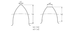
最後に、上記(b)に挙げられる「正面噛み合い圧力角を小さくする」方法と、上記(c)に挙げられる「有効歯丈を大きくする」方法とについて検討する。有効歯丈がモジュールの2.25倍に設定されたものが一般的に「並歯」と呼ばれる通常歯丈の歯車である。これに対して、有効歯丈がモジュールの2.25倍よりも大きい値に設定されたものが所謂「高歯」である。歯車をこのような「高歯」にすることで、歯先円直径が大きくなり、噛み合い長さが大きくなるので、正面噛み合い率(εa)を大きくすることが可能である。しかしながら、図5に示すように、有効歯丈を大きくすると(h1>h2)、歯先の頂部幅(トップランド)が小さくなるため(w1<w2)、歯車の耐久性が低下し、歯先が破損する虞がある。ここで、歯先の細りに対する対策として、上記(b)に挙げられる「歯車の正面噛み合い圧力角を小さくする」方法を採用すれば、歯先の細りを緩和することができるので、正面噛み合い率(εa)を大きくしながら、歯車の耐久性を向上させることが可能である。しかしながら、それでも、特にモジュールを小さくした場合(歯を小さくした場合)は、有効歯丈を大きくすると、歯先の頂部幅はより一層小さくなるので、破損の虞が増すことになる。従って、上述のように、1段目の歯車よりも2段目の歯車の方が大きいモジュールとすることが好ましいとすると、モジュールの小さい1段目の歯車については、有効歯丈を大きくしない方が好ましいと言える。
以上の検討結果を踏まえ、本実施形態では、1段目の歯車と2段目の歯車との関係について以下のように設定している。
まず、モジュールについては、1段目の歯車よりも2段目の歯車の方が大きな荷重を受けることを考慮し、2段目の歯車の耐久性を確保するため、1段目の歯車よりも2段目の歯車を大きいモジュールに設定している。言い換えれば、1段目の歯車は2段目の歯車よりも受ける荷重が小さいので、優先的にモジュールを小さくすることができる。従って、1段目の歯車については、2段目の歯車よりも小さいモジュールにすることで、正面噛み合い率(εa)及び重なり噛み合い率(εb)を優先的に大きくすることができる。
次に、ねじれ角については、1段目の歯車よりも2段目の歯車の方が大きな荷重を受けることを考慮し、2段目の歯車を支持する転がり軸受の摩耗や破損を抑制するため、2段目の歯車よりも1段目の歯車を大きいねじれ角に設定している。これにより、2段目の歯車を支持する転がり軸受の摩耗や破損を抑制しつつ、1段目の歯車については、重なり噛み合い率(εb)を優先的に大きくすることができる。
有効歯丈については、モジュールの大きい2段目の歯車の方がモジュールの小さい1段目の歯車よりも歯先が細くなることによる強度低下が生じにくいので、2段目の歯車を1段目の歯車よりも有効歯丈を大きく設定している。これにより、1段目の歯車の強度低下を抑制しつつ、2段目の歯車については、正面噛み合い率(εa)を優先的に大きくすることができる。
このように、本実施形態では、1段目の歯車と2段目の歯車の、モジュール、ねじれ角、有効歯丈について上記の如く設定することで、歯車や転がり軸受の耐久性を確保しつつ、正面噛み合い率(εa)や重なり噛み合い率(εb)を効果的に大きくし、噛み合い伝達誤差を低減することが可能となる。これにより、噛み合い伝達誤差に起因する振動を抑制することができ、低振動化に優れたインホイールモータ駆動装置を提供できるようになる。また、モジュール、ねじれ角、有効歯丈の各要素の調整は、歯車の軸方向寸法に影響を与えるものではないので、これらの要素を変更することに伴う軸方向寸法の増大も生じず、インホイールモータ駆動装置の小型化も図ることが可能である。
また、有効歯丈を大きくすることに伴う歯先の細り(耐久性の低下)が懸念される場合は、正面噛み合い圧力角を小さくすることにより、歯先の細りを緩和することが可能である。特に、有効歯丈を大きくする2段目の歯車については、歯先が細くなることが考えられる。加えて、2段目の歯車には1段目の歯車よりも大きな荷重が作用するため、歯先が細くなることによる破損が懸念される。よって、2段目の歯車については、歯先の細りを緩和し耐久性を向上させるために、1段目の歯車よりも小さい正面噛み合い圧力角に設定することが好ましい。また、正面噛み合い圧力角を小さくすることで、2段目の歯車においては、正面噛み合い率(εa)が大きくなり、噛み合い伝達誤差を低減することができる。なお、2段目の歯車の耐久性について特に懸念がない場合は、1段目の歯車と2段目の歯車を同じ正面噛み合い圧力角に設定してもよい。
以上、本発明の実施形態について説明したが、本発明は上述の実施形態に何ら限定されるものではなく、本発明の要旨を逸脱しない範囲内において、さらに種々なる形態で実施し得ることは勿論である。
上述の実施形態では、入力軸27と中間軸28と出力軸29の3つの平行な軸を備える3軸2段の減速機構を例に説明したが、本発明は、中間軸28を2つ以上備える4軸以上の減速機構にも適用可能である。
21 インホイールモータ駆動装置
27 入力軸
28 中間軸
29 出力軸
30 入力歯車
31 入力側中間歯車
32 出力側中間歯車
35 出力歯車
39 平行軸歯車減速機構
A 電動モータ部
B 減速機部
C 車輪用軸受部
27 入力軸
28 中間軸
29 出力軸
30 入力歯車
31 入力側中間歯車
32 出力側中間歯車
35 出力歯車
39 平行軸歯車減速機構
A 電動モータ部
B 減速機部
C 車輪用軸受部
Claims (2)
- 電動モータ部と、車輪用軸受部と、前記電動モータ部の回転を前記車輪用軸受部へ減速して伝達する減速機部とを備えたインホイールモータ駆動装置において、
前記減速機部は、前記電動モータ部の回転軸と一体に回転し、入力歯車を有する入力軸と、前記車輪用軸受部の回転軸と一体に回転し、出力歯車を有する出力軸と、前記入力歯車と噛み合う入力側中間歯車、及び、前記出力歯車と噛み合う出力側中間歯車を有する中間軸とを備えた3軸以上の平行軸歯車減速機構であり、
前記入力歯車、前記出力歯車、前記入力側中間歯車及び前記出力側中間歯車は、はすば歯車であって、
前記入力歯車及び前記入力側中間歯車よりも、前記出力歯車及び前記出力側中間歯車が、大きいモジュールで構成され、
前記出力歯車及び前記出力側中間歯車よりも、前記入力歯車及び前記入力側中間歯車が、大きいねじれ角で構成され、
前記入力歯車及び前記入力側中間歯車よりも、前記出力歯車及び前記出力側中間歯車が、大きい有効歯丈で構成されていることを特徴とするインホイールモータ駆動装置。 - 前記出力歯車及び前記出力側中間歯車よりも、前記入力歯車及び前記入力側中間歯車が、小さい正面噛み合い圧力角で構成されている請求項1に記載のインホイールモータ駆動装置。
Priority Applications (3)
| Application Number | Priority Date | Filing Date | Title |
|---|---|---|---|
| EP19858831.1A EP3851310A4 (en) | 2018-09-10 | 2019-09-09 | IN-WHEEL MOTOR DRIVE DEVICE |
| CN201980058904.0A CN112672903B (zh) | 2018-09-10 | 2019-09-09 | 轮内电动机驱动装置 |
| US17/268,332 US11679663B2 (en) | 2018-09-10 | 2019-09-09 | In-wheel motor drive device |
Applications Claiming Priority (2)
| Application Number | Priority Date | Filing Date | Title |
|---|---|---|---|
| JP2018-168800 | 2018-09-10 | ||
| JP2018168800A JP7048460B2 (ja) | 2018-09-10 | 2018-09-10 | インホイールモータ駆動装置 |
Publications (1)
| Publication Number | Publication Date |
|---|---|
| WO2020054650A1 true WO2020054650A1 (ja) | 2020-03-19 |
Family
ID=69778319
Family Applications (1)
| Application Number | Title | Priority Date | Filing Date |
|---|---|---|---|
| PCT/JP2019/035329 Ceased WO2020054650A1 (ja) | 2018-09-10 | 2019-09-09 | インホイールモータ駆動装置 |
Country Status (5)
| Country | Link |
|---|---|
| US (1) | US11679663B2 (ja) |
| EP (1) | EP3851310A4 (ja) |
| JP (1) | JP7048460B2 (ja) |
| CN (1) | CN112672903B (ja) |
| WO (1) | WO2020054650A1 (ja) |
Families Citing this family (3)
| Publication number | Priority date | Publication date | Assignee | Title |
|---|---|---|---|---|
| US11446996B2 (en) * | 2019-11-04 | 2022-09-20 | Toyota Motor Engineering & Manufacturing North America, Inc. | Selectively movable electric propulsion motor and method for positioning the same |
| IT202000006940A1 (it) * | 2020-04-02 | 2021-10-02 | Brist Axle Systems S R L | Sospensione indipendente |
| JP2023004083A (ja) * | 2021-06-25 | 2023-01-17 | ナブテスコ株式会社 | 減速機、及び、回転装置 |
Citations (2)
| Publication number | Priority date | Publication date | Assignee | Title |
|---|---|---|---|---|
| JP2018071686A (ja) * | 2016-10-31 | 2018-05-10 | Ntn株式会社 | インホイールモータ駆動装置 |
| JP2018114834A (ja) | 2017-01-18 | 2018-07-26 | Ntn株式会社 | インホイールモータ駆動装置 |
Family Cites Families (16)
| Publication number | Priority date | Publication date | Assignee | Title |
|---|---|---|---|---|
| US5087229A (en) * | 1991-05-06 | 1992-02-11 | General Motors Corporation | Independently suspended steerable motor wheel apparatus |
| US8002060B2 (en) * | 2006-02-17 | 2011-08-23 | Honda Motor Co., Ltd. | Vehicle wheel driving apparatus and electric motor |
| JP4225342B2 (ja) * | 2006-10-04 | 2009-02-18 | トヨタ自動車株式会社 | インホイールモータ構造 |
| JP5413633B2 (ja) * | 2007-10-19 | 2014-02-12 | アイシン・エィ・ダブリュ株式会社 | ハイブリッド駆動装置 |
| JP5565388B2 (ja) * | 2011-03-28 | 2014-08-06 | アイシン・エィ・ダブリュ株式会社 | インホイールモータ駆動装置 |
| JP5809927B2 (ja) * | 2011-10-28 | 2015-11-11 | Ntn株式会社 | インホイールモータ駆動装置 |
| JP6192921B2 (ja) * | 2012-11-08 | 2017-09-06 | Ntn株式会社 | モータ搭載自動車の低温時駆動制御装置 |
| KR101441813B1 (ko) * | 2013-06-25 | 2014-09-18 | 현대위아 주식회사 | 전기자동차의 후륜 구동장치 |
| JP2015110962A (ja) * | 2013-12-06 | 2015-06-18 | 日産自動車株式会社 | ギヤカップリング及びこれを備えた車両用ホイール駆動装置 |
| KR101538080B1 (ko) * | 2013-12-10 | 2015-07-20 | 현대모비스 주식회사 | 인휠 어셈블리 및 이를 구비하는 차량 |
| CN104776163A (zh) * | 2015-04-16 | 2015-07-15 | 凤阳县鼎盛矿山设备有限公司 | 立轴式二级圆柱齿轮减速器 |
| JP6853622B2 (ja) * | 2015-09-29 | 2021-03-31 | Ntn株式会社 | インホイールモータ駆動装置、およびインホイールモータ駆動装置とサスペンション装置の連結構造 |
| JP2017065671A (ja) | 2015-09-30 | 2017-04-06 | Ntn株式会社 | インホイールモータ駆動装置 |
| JP2018009638A (ja) * | 2016-07-13 | 2018-01-18 | Ntn株式会社 | 遊星歯車装置 |
| JP2018070095A (ja) * | 2016-11-04 | 2018-05-10 | Ntn株式会社 | インホイールモータ駆動装置 |
| CN108223699A (zh) * | 2018-01-31 | 2018-06-29 | 上齿集团有限公司 | 新能源电动物流车后桥驱动主减速器 |
-
2018
- 2018-09-10 JP JP2018168800A patent/JP7048460B2/ja not_active Expired - Fee Related
-
2019
- 2019-09-09 WO PCT/JP2019/035329 patent/WO2020054650A1/ja not_active Ceased
- 2019-09-09 EP EP19858831.1A patent/EP3851310A4/en not_active Withdrawn
- 2019-09-09 CN CN201980058904.0A patent/CN112672903B/zh active Active
- 2019-09-09 US US17/268,332 patent/US11679663B2/en active Active
Patent Citations (2)
| Publication number | Priority date | Publication date | Assignee | Title |
|---|---|---|---|---|
| JP2018071686A (ja) * | 2016-10-31 | 2018-05-10 | Ntn株式会社 | インホイールモータ駆動装置 |
| JP2018114834A (ja) | 2017-01-18 | 2018-07-26 | Ntn株式会社 | インホイールモータ駆動装置 |
Non-Patent Citations (1)
| Title |
|---|
| See also references of EP3851310A4 |
Also Published As
| Publication number | Publication date |
|---|---|
| US11679663B2 (en) | 2023-06-20 |
| CN112672903A (zh) | 2021-04-16 |
| EP3851310A1 (en) | 2021-07-21 |
| JP2020040489A (ja) | 2020-03-19 |
| JP7048460B2 (ja) | 2022-04-05 |
| EP3851310A4 (en) | 2022-06-01 |
| CN112672903B (zh) | 2024-09-10 |
| US20210316605A1 (en) | 2021-10-14 |
Similar Documents
| Publication | Publication Date | Title |
|---|---|---|
| US10938272B2 (en) | In-wheel motor drive device | |
| WO2020054650A1 (ja) | インホイールモータ駆動装置 | |
| WO2021095418A1 (ja) | インホイールモータ駆動装置 | |
| US10933737B2 (en) | In-wheel motor drive device | |
| JP6781608B2 (ja) | インホイールモータ駆動装置 | |
| CN111703293A (zh) | 轮内电动机驱动装置 | |
| JP7126908B2 (ja) | 電動車両駆動装置及びインホイールモータ駆動装置 | |
| US10894473B2 (en) | In-wheel motor drive device | |
| US11662010B2 (en) | Vehicle drive device | |
| WO2021176951A1 (ja) | インホイールモータ駆動装置 | |
| JP2020046055A (ja) | インホイールモータ駆動装置 | |
| JP2018070095A (ja) | インホイールモータ駆動装置 | |
| JP2017003048A (ja) | 車両用モータ駆動装置 |
Legal Events
| Date | Code | Title | Description |
|---|---|---|---|
| 121 | Ep: the epo has been informed by wipo that ep was designated in this application |
Ref document number: 19858831 Country of ref document: EP Kind code of ref document: A1 |
|
| NENP | Non-entry into the national phase |
Ref country code: DE |
|
| ENP | Entry into the national phase |
Ref document number: 2019858831 Country of ref document: EP Effective date: 20210412 |