WO2020059205A1 - 光コネクタシステム及びシャッター付き光コネクタ - Google Patents
光コネクタシステム及びシャッター付き光コネクタ Download PDFInfo
- Publication number
- WO2020059205A1 WO2020059205A1 PCT/JP2019/019614 JP2019019614W WO2020059205A1 WO 2020059205 A1 WO2020059205 A1 WO 2020059205A1 JP 2019019614 W JP2019019614 W JP 2019019614W WO 2020059205 A1 WO2020059205 A1 WO 2020059205A1
- Authority
- WO
- WIPO (PCT)
- Prior art keywords
- optical connector
- shutter
- housing
- guide portion
- optical
- Prior art date
- Legal status (The legal status is an assumption and is not a legal conclusion. Google has not performed a legal analysis and makes no representation as to the accuracy of the status listed.)
- Ceased
Links
Images


Classifications
-
- G—PHYSICS
- G02—OPTICS
- G02B—OPTICAL ELEMENTS, SYSTEMS OR APPARATUS
- G02B6/00—Light guides; Structural details of arrangements comprising light guides and other optical elements, e.g. couplings
- G02B6/24—Coupling light guides
- G02B6/36—Mechanical coupling means
- G02B6/38—Mechanical coupling means having fibre to fibre mating means
- G02B6/3807—Dismountable connectors, i.e. comprising plugs
- G02B6/3833—Details of mounting fibres in ferrules; Assembly methods; Manufacture
- G02B6/3847—Details of mounting fibres in ferrules; Assembly methods; Manufacture with means preventing fibre end damage, e.g. recessed fibre surfaces
- G02B6/3849—Details of mounting fibres in ferrules; Assembly methods; Manufacture with means preventing fibre end damage, e.g. recessed fibre surfaces using mechanical protective elements, e.g. caps, hoods, sealing membranes
-
- G—PHYSICS
- G02—OPTICS
- G02B—OPTICAL ELEMENTS, SYSTEMS OR APPARATUS
- G02B6/00—Light guides; Structural details of arrangements comprising light guides and other optical elements, e.g. couplings
- G02B6/24—Coupling light guides
- G02B6/36—Mechanical coupling means
- G02B6/38—Mechanical coupling means having fibre to fibre mating means
- G02B6/3807—Dismountable connectors, i.e. comprising plugs
- G02B6/381—Dismountable connectors, i.e. comprising plugs of the ferrule type, e.g. fibre ends embedded in ferrules, connecting a pair of fibres
- G02B6/3825—Dismountable connectors, i.e. comprising plugs of the ferrule type, e.g. fibre ends embedded in ferrules, connecting a pair of fibres with an intermediate part, e.g. adapter, receptacle, linking two plugs
-
- G—PHYSICS
- G02—OPTICS
- G02B—OPTICAL ELEMENTS, SYSTEMS OR APPARATUS
- G02B6/00—Light guides; Structural details of arrangements comprising light guides and other optical elements, e.g. couplings
- G02B6/24—Coupling light guides
- G02B6/36—Mechanical coupling means
- G02B6/38—Mechanical coupling means having fibre to fibre mating means
- G02B6/3807—Dismountable connectors, i.e. comprising plugs
- G02B6/3873—Connectors using guide surfaces for aligning ferrule ends, e.g. tubes, sleeves, V-grooves, rods, pins, balls
- G02B6/3885—Multicore or multichannel optical connectors, i.e. one single ferrule containing more than one fibre, e.g. ribbon type
-
- G—PHYSICS
- G02—OPTICS
- G02B—OPTICAL ELEMENTS, SYSTEMS OR APPARATUS
- G02B6/00—Light guides; Structural details of arrangements comprising light guides and other optical elements, e.g. couplings
- G02B6/24—Coupling light guides
- G02B6/36—Mechanical coupling means
- G02B6/40—Mechanical coupling means having fibre bundle mating means
- G02B6/406—Mechanical coupling means having fibre bundle mating means of the ferrule type, connecting a plurality of pairs of ferrules
Definitions
- the present invention relates to an optical connector system and an optical connector with a shutter.
- Patent Document 1 describes an optical connector in which a shutter is provided in an insertion port.
- the mating optical connector when the mating optical connector is inserted into the insertion slot, the mating optical connector comes into contact with the shutter, and the shutter is pushed open.
- An object of the present invention is to provide an optical connector with a shutter capable of suppressing intrusion of dust.
- a main invention for achieving the above object is an optical connector system including a first optical connector and a second optical connector connected to the first optical connector, wherein the first optical connector has a first shutter. Wherein the first shutter falls down to the side of the second optical connector and opens when the first shutter comes into contact with the second optical connector.
- dust adhering to the outer surface of the shutter can be suppressed from entering the inside of the optical connector.
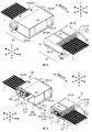
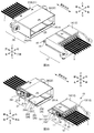
- FIG. 1A and 1B are perspective views of the optical connector system according to the first embodiment.
- 2A and 2B are perspective views of the optical connector system according to the first embodiment as viewed from another angle.
- 3A and 3B are perspective views of the optical connector system with the shutter opened.
- 4A and 4B are perspective views of the optical connector system with the shutter opened, as viewed from another angle.
- FIG. 5A is a sectional view of the vicinity of the first shutter 15 and the first housing 12 of the present embodiment.
- FIG. 5B is a cross-sectional view of the vicinity of the first shutter 15 and the first housing 12 of the reference example.
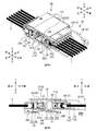
- 6A and 6B are explanatory diagrams of a state where the second shutter 25 has begun to open.
- FIGS. 7A and 7B are explanatory diagrams of a state where the first shutter 15 has begun to open.
- FIGS. 8A and 8B are explanatory diagrams illustrating a state in which the first optical connector 10 and the second optical connector 20 are further brought close to each other after the second shutter 25 is opened.
- FIG. 9A and FIG. 9B are explanatory diagrams of a state when the first optical connector 10 and the second optical connector 20 are connected.
- An optical connector system comprising a first optical connector and a second optical connector connected to the first optical connector, wherein the first optical connector has a first shutter, and the first shutter is An optical connector system which is characterized in that it comes into contact with the second optical connector and falls down to the side of the second optical connector and opens. According to such an optical connector system, dust adhering to the outer surface of the first shutter can be suppressed from entering the inside of the first optical connector.
- the first shutter has a main body, a rotating shaft, and a contact portion, and the contact portion is disposed on a side opposite to the main body when viewed from the rotating shaft, and the contact portion is It is preferable that the first shutter is rotated about the rotation axis by being pressed from the second optical connector, and the main body is tilted toward the second optical connector and opened. Thus, when the first optical connector and the second optical connector are connected, the first shutter can be tilted toward the second optical connector and opened.
- the second optical connector has a second shutter.
- the first optical connector is provided inside the second housing of the second optical connector. It is desirable that the first housing of the optical connector be inserted. Thereby, it is possible to prevent dust from entering the inside of the second optical connector.
- the first optical connector has a projection
- the second optical connector has a second shutter
- the projection is After the second shutter is pushed open, it is desirable that the first shutter be opened. Thereby, the first shutter is easily opened.
- the second optical connector has a second shutter, It is preferable that when the first optical connector and the second optical connector are brought close to each other, the outer surface of the first shutter and the outer surface of the second shutter come into contact with each other. Thus, dust adhering to the outer surface of the first shutter can be sandwiched between the first shutter and the second shutter, and the inside of the second optical connector can be prevented from being contaminated with dust.
- the first shutter has a first guide section
- the second shutter has a second guide section.
- the first optical connector is brought into contact with the first guide section and the second guide section. It is desirable that relative movement in the width direction between the first optical connector and the second optical connector be restricted. Thereby, the displacement in the width direction between the first optical connector and the second optical connector can be suppressed.
- One of the first guide portion and the second guide portion is a linear convex portion, and the other is a linear concave portion, and the convex portion is provided when the first shutter and the second shutter are closed.
- the concave portion extends along a direction perpendicular to the attaching / detaching direction and the width direction, and in a state where the first shutter and the second shutter are opened, the convex portion and the concave portion are along the attaching / detaching direction. It is desirable. Thereby, the movement of the first optical connector and the second optical connector in the attaching / detaching direction can be guided by the first guide portion and the second guide portion.
- the first optical connector has a first housing having the first shutter, and an outer guide portion is formed on an outer surface of the first housing, and a position of the outer guide portion in the width direction is provided. Is preferably common to the position of the first guide portion in the width direction. Accordingly, the movement of the first optical connector and the second optical connector in the attaching / detaching direction can be guided by the second guide portion that guides the first guide portion and the outer guide portion.
- the first optical connector preferably has a first housing, and the first housing preferably has a step portion for receiving an end of the first shutter in a closed state. Thereby, invasion of dust can be suppressed.
- an inclined surface is formed at an inner end of the first shutter in a closed state. This can prevent the first shutter from being caught inside the second optical connector.
- the second optical connector has a first housing portion that houses the first shutter of the first optical connector.
- the first shutter of the first optical connector that is opened outward can be accommodated inside the second optical connector.
- An optical connector with a shutter comprising: a ferrule, a housing for accommodating the ferrule, and a shutter for closing an opening of the housing, wherein the shutter is tilted and opened to the other optical connector side.
- 1A and 1B are perspective views of the optical connector system according to the first embodiment.
- 2A and 2B are perspective views of the optical connector system according to the first embodiment as viewed from another angle.
- 3A and 3B are perspective views of the optical connector system with the shutter opened.
- 4A and 4B are perspective views of the optical connector system with the shutter opened, as viewed from another angle.
- each direction is defined as shown in FIG. 1A.
- the direction in which the first optical connector 10 and the second optical connector 20 are connected or disconnected is referred to as a “detachment direction”.
- the side of the second optical connector 20 in the attaching / detaching direction is referred to as “front”, and the opposite side is referred to as “rear”.
- the side of the first optical connector 10 in the attaching / detaching direction is referred to as “front” and the opposite side is referred to as “back”.
- the direction parallel to the rotation axis of the shutter (the first rotation axis 152 and the second rotation axis 252) is referred to as a “width direction” or a “left-right direction”, and when viewed from behind (or viewed from the near side). ) Is defined as “right” and the opposite side is defined as “left”. Further, a direction perpendicular to the attaching / detaching direction and the width direction is referred to as a “vertical direction”.
- the optical connector system of the present embodiment has a first optical connector 10 and a second optical connector 20.
- the optical fiber 1 of the first optical connector 10 and the optical fiber 1 of the second optical connector 20 are optically connected.
- the first optical connector 10 and the second optical connector 20 are optical connectors with shutters.
- the first optical connector 10 may be constituted by an optical connector with a shutter
- the second optical connector 20 may not be an optical connector with a shutter (the second optical connector 20 may not have the second shutter 25).
- the first optical connector 10 is a plug-side connector and a male connector here. However, the first optical connector 10 may be a receptacle-side connector instead of a plug-side connector.
- the first optical connector 10 has a plurality of first optical modules 11 and a first housing 12. In other words, the first optical connector 10 has a plurality of first ferrules 11A and a first housing 12.
- the first optical module 11 is a module attached to the end of the optical fiber 1 (here, an optical fiber tape).
- the first optical module 11 has a first ferrule 11A and a first holding mechanism 11B.
- the first ferrule 11A is a member (ferrule) for holding an end of the optical fiber 1.
- the first ferrule 11A is an MT type optical connector (F12 type optical connector specified in JIS C5981) here.
- the first holding mechanism 11B is a mechanism that presses the first ferrule 11A to the front side and holds the first ferrule 11A in the first housing 12 (specifically, the first inner housing 13) so as to be able to retreat.
- the first holding mechanism 11B is configured by, for example, a pin clamp, a spring, a spring push, or the like. Note that the first optical connector 10 may not include the first holding mechanism 11B as long as the first optical connector 10 includes the plurality of first ferrules 11A.
- the plurality of first optical modules 11 are arranged side by side along the width direction. Therefore, the plurality of first ferrules 11A are also arranged along the width direction.
- the first housing 12 is a member that houses the first optical module 11 (or the first ferrule 11A).
- the first housing 12 has a first inner housing 13 and a first outer housing 14.
- the first housing 12 may be composed of one part.
- the first inner housing 13 is a member that houses the first optical module 11 (or the first ferrule 11A).
- the first outer housing 14 is a member that houses the first inner housing 13.
- the first outer housing 14 is a wide rectangular tubular member.
- the optical fiber 1 extends from the rear side of the first outer housing 14 having a rectangular tube shape, and the front end of the optical fiber 1 is held by the first ferrule 11A.
- the first housing 12 (specifically, the first outer housing 14) has a first shutter 15.
- the first shutter 15 is a member that closes an opening on the front side of the first outer housing 14 having a rectangular cylindrical shape. Since the first shutter 15 closes the front side of the first housing 12, it is possible to prevent dust from adhering to the first ferrule 11A. As shown in FIGS. 3B, 4A, and 4B, the first shutter 15 can be opened outward by falling outward (front side; side of the second optical connector 20).
- the first shutter 15 is a plate-shaped member. The first shutter 15 is perpendicular to the attaching / detaching direction when the first shutter 15 is closed, and is parallel to the up / down direction when the first shutter 15 is open.
- dust may adhere to the outer surface of the first shutter 15 closing the opening of the first housing 12. If the first shutter 15 is opened so as to fall inward, dust adhering to the outer surface may enter the inside of the first optical connector 10 and adhere to the first ferrule 11A (the first optical connector 10 may be attached to the first ferrule 11A). Garbage can be contaminated). On the other hand, in the present embodiment, since the first shutter 15 can be tilted outward (to the front side; the side of the second optical connector 20) and opened, dust attached to the first shutter 15 is removed from the first optical connector 10. Intrusion into the inside can be suppressed.
- the outer surface of the opened first shutter 15 faces the side opposite to the side of the second ferrule 21A of the second optical connector 20 (described later: FIG. 8A). And FIG. 8B), and the insertion of the first shutter 15 to which dust adheres into the second optical connector 20 is permitted. Further, as described later, in the present embodiment, dust attached to the first shutter 15 is in a state of being sandwiched between the first shutter 15 and the second shutter 25 (see FIG. 7B described later). Since the dust adhering to the first shutter 15 is suppressed from adhering to the second ferrule 21A of the second optical connector 20, the first shutter 15 is allowed to fall down to the second optical connector 20 and open. ing.
- the first shutter 15 can be tilted outward (toward the front side; the side of the second optical connector 20) and opened, the distance between the first shutter 15 and the first ferrule 11A in the front-rear direction is reduced.
- a second shutter 25 described later falls down and opens inward, it is necessary to arrange the second shutter 25 and the second ferrule 21A apart in the front-rear direction. For this reason, the first shutter 25 is required.
- the first shutter 15 has a first main body 151, a first rotation shaft 152, and a contact part 153.
- the first main body 151 is a plate-like part that forms the main body of the first shutter 15. When the first shutter 15 is closed, the front opening of the first outer housing 14 having the shape of a rectangular tube is closed.
- a first guide 151A is formed on an outer surface (a front surface; a surface facing the second optical connector 20) of the first main body 151.
- the first guide portion 151A is a portion that suppresses a displacement in the width direction of the first optical connector 10 with respect to the second optical connector 20 (a relative movement in the width direction between the first optical connector 10 and the second optical connector 20). Is the part that regulates).
- the first guide portion 151A is a portion that guides the first optical connector 10 to the second optical connector 20 so as to be movable in the attaching / detaching direction.
- the first guide portion 151A is formed as a linear concave portion (groove portion).
- the first guide portion 151A can be formed as a linear convex portion (in this case, the second guide portion 251A is formed as a linear concave portion).
- the linear first guide portion 151A has a shape along the up-down direction (the direction perpendicular to the attaching / detaching direction and the width direction) when the first shutter 15 is closed. When the first shutter 15 is open, the linear first guide portion 151A is in the attaching / detaching direction.
- the first rotation shaft 152 is a portion that becomes the rotation shaft of the first shutter 15.
- the first rotation shaft 152 is formed along the width direction.
- the first rotation shaft 152 is formed at the lower front edge of the first housing 12.
- a closing force is applied to the first shutter 15 by a first spring (not shown) provided on the first rotating shaft 152.
- the contact portion 153 is a portion that comes into contact with the second optical connector 20.
- the contact portion 153 is disposed on the side opposite to the first main body 151 when viewed from the first rotation shaft 152.
- the contact portion 153 has a shape protruding downward from the first rotation shaft 152.
- the contact portion 153 is pressed rearward, the first shutter 15 rotates about the first rotation shaft 152, and the first shutter 15 can be tilted forward and opened.
- the contact portion 153 contacts the second optical connector 20 and is pressed rearward from the second optical connector 20, As a result, the first shutter 15 falls forward and opens.
- the first housing 12 further has a protrusion 16.
- the protruding portions 16 are portions that protrude forward (toward the second optical connector 20) from the left and right edges of the first housing 12.
- the protruding portion 16 is disposed so as to protrude forward from the first shutter 15.
- the first housing 12 further has a first outer guide portion 17.
- the first outer guide portion 17 is a guide portion formed on an outer surface (here, a lower surface) of the first housing 12 (here, the first outer housing 14).
- the first outer guide portion 17 is a portion that suppresses a displacement in the width direction of the first optical connector 10 with respect to the second optical connector 20 (relative movement in the width direction between the first optical connector 10 and the second optical connector 20). Is the part that regulates).
- the first outer guide portion 17 is a portion that guides the first optical connector 10 to the second optical connector 20 so as to be movable in the attaching / detaching direction.
- the first outer guide portion 17 is formed as a linear concave portion.
- the first outer guide portion 17 can be formed as a linear convex portion.
- the linear first guide portion 151A has a shape along the attaching / detaching direction.
- the position of the first outer guide portion 17 in the width direction is common to the position of the first guide portion 151A of the first shutter 15 in the width direction. Thereby, the first optical connector 10 can be guided by the same guide portion (the second guide portion 251A).
- FIG. 5A is a cross-sectional view of the vicinity of the first shutter 15 and the first housing 12 of the present embodiment.
- a step portion 141 is formed at the upper front edge of the first housing 12.
- the step portion 141 is a step-shaped portion for accommodating the end of the first shutter 15 in a closed state.
- the step portion 141 has a stopper surface 141A and an upper facing surface 141B.
- the stopper surface 141A is a surface serving as a stopper of the first shutter 15 that is in contact with the first shutter 15 and is urged in the closing direction.
- the stopper surface 141A is configured as a surface perpendicular to the attaching / detaching direction.
- the upper facing surface 141B is a surface facing the end (upper edge) of the first shutter 15.
- the upper facing surface 141B is a surface that is perpendicular to the up-down direction and that faces downward.
- a part of the upper front edge of the first housing 12 projects forward from the stopper surface 141A, and the lower surface of the portion projecting forward from the stopper surface 141A forms an upper facing surface 141B. I have.
- FIG. 5B is a cross-sectional view of the vicinity of the first shutter 15 and the first housing 12 of the reference example.
- a step portion 141 is not formed on the upper front edge of the first housing 12. That is, in the reference example, the upper facing surface 141B is not formed.
- the upper facing surface 141B is disposed so as to cover the gap between the first shutter 15 and the stopper surface 141A from above.
- the gap (dust entry route) between the first shutter 15 and the first housing 12 (the step portion 141) can be lengthened, and the dust entry route can be increased. Since it can be bent, intrusion of dust from a gap can be suppressed.
- a first inclined surface 151B is formed at an end (upper edge) of the first shutter 15.
- the first inclined surface 151B is arranged at an inner end (upper rear edge) of the first shutter 15 when the first shutter 15 is closed. That is, the first inclined surface 151B is a surface facing rearward and upward when the first shutter 15 is closed. Therefore, the first inclined surface 151B faces forward and upward when the first shutter 15 is open (see the dotted line in FIG. 5A). Accordingly, when the first optical connector 10 and the second optical connector 20 are connected, the first shutter 15 can be prevented from being caught inside the second optical connector 20 (see FIG. 8B described later).
- the second optical connector 20 is a connector on the receptacle side here, and is a female connector. However, the second optical connector 20 may be a plug connector instead of a receptacle connector.
- the second optical connector 20 has a plurality of second optical modules 21 and a second housing 22. In other words, the second optical connector 20 has a plurality of second ferrules 21A and a second housing 22.
- the second optical module 21 is a module attached to the end of the optical fiber 1 (here, an optical fiber tape).
- the second optical module 21 has a plurality of second ferrules 21A and a second holding mechanism 21B.
- the structure of the second optical module 21 is almost the same as the structure of the first optical module 11.
- the second optical connector 20 may not include the second holding mechanism 21B as long as the second optical connector 20 includes a plurality of second ferrules 21A.
- the plurality of second optical modules 21 are arranged side by side along the width direction. For this reason, the second ferrule 21A is also arranged along the width direction.
- Each second ferrule 21A is connected to each first ferrule 11A of the first optical connector 10.
- the second housing 22 is a member that houses the second optical module 21 (or the second ferrule 21A).
- the second housing 22 has a second inner housing 23 and a second outer housing 24.
- the second housing 22 may be composed of one part.
- the second inner housing 23 is a member that houses the second optical module 21.
- the second outer housing 24 is a member that houses the second inner housing 23.
- the second outer housing 24 is a wide rectangular tubular member.
- the optical fiber 1 extends from the inner side of the second cylindrical outer housing 24, and the front end of the optical fiber 1 is held by the second ferrule 21A.
- the first housing 12 (the first outer housing 14) of the first optical connector 10 is inserted inside the second housing 22 (the second outer housing 24) in the shape of a rectangular tube.
- the second optical connector 20 is a female connector
- the first optical connector 10 is a male connector.
- the second housing 22 (specifically, the second outer housing 24) has a second shutter 25.
- the second shutter 25 is a member that closes the front opening of the second outer housing 24 having a rectangular cylindrical shape. By the second shutter 25 closing the front side of the second housing 22, it is possible to prevent dust from adhering to the second ferrule 21A.
- the second shutter 25 is arranged on the back side of the front edge of the opening of the second housing 22 having a rectangular cylindrical shape. For this reason, the edge of the opening of the second housing 22 having a rectangular cylindrical shape protrudes forward from the second shutter 25. As shown in FIG. 3A, the second shutter 25 can be tilted inward (backward) and opened.
- the second shutter 25 is a plate-shaped member, and is perpendicular to the attaching / detaching direction when the second shutter 25 is closed, and parallel to the attaching / detaching direction when the second shutter 25 is open.
- the second shutter 25 has a second main body 251 and a second rotation shaft 252.
- the second main body part 251 is a plate-shaped part that constitutes the main body of the second shutter 25, and is a part that closes the front opening of the second outer housing 24 having a rectangular cylindrical shape.
- the second rotation axis 252 is a part that becomes the rotation axis of the second shutter 25.
- the second rotation shaft 252 is formed along the width direction.
- the second rotation shaft 252 is formed on the lower surface of the inner wall of the second housing 22.
- a second spring (not shown) provided on the second rotating shaft 252 urges the second shutter 25 with a force in the closing direction.
- the second rotation shaft 252 is disposed below the first rotation shaft 152 (see FIG. 6B described later).
- the second rotation shaft 252 is disposed on the back side of the front edge (the edge of the opening) of the second outer housing 24. Therefore, when the second shutter 25 contacts the first optical connector 10 and opens, the first housing 12 is fitted inside the second housing 22 (described later).
- a second guide portion 251A is formed on the outer surface of the second shutter 25 (a surface on the near side; a surface facing the first optical connector 10).
- the second guide part 251A is a part that suppresses the displacement of the second optical connector 20 in the width direction with respect to the first optical connector 10. That is, the second guide portion 251A is a portion that, together with the first guide portion 151A, regulates relative movement in the width direction between the first optical connector 10 and the second optical connector 20.
- the second guide part 251A is a part that guides the second optical connector 20 to the first optical connector 10 so as to be movable in the attaching / detaching direction.
- the second guide part 251A is a part that guides the movement of the first optical connector 10 and the second optical connector 20 in the attaching and detaching direction together with the first guide part 151A.
- the second guide portion 251A is formed as a linear convex portion (projecting ridge).
- the second guide portion 251A can be formed as a linear concave portion (in this case, the first guide portion 151A is formed as a linear convex portion).
- the linear second guide portion 251A has a shape along the vertical direction (the direction perpendicular to the attaching / detaching direction and the width direction).
- the linear second guide portion 251A follows the mounting / removing direction.
- the second housing 22 (the second outer housing 24) has a second housing portion 262.
- the second housing 262 is a housing (housing space) for housing the second shutter 25.
- the second housing portion 262 is disposed inside the second outer housing 24 having a rectangular cylindrical shape, and is formed on the inner side of the second rotation shaft 252. When the second shutter 25 is opened (falls inward), the second shutter 25 is housed in the second housing part 262.
- the second housing 22 (the second outer housing 24) has a first housing portion 261.
- the first housing 261 is a housing (housing space) for housing the first shutter 15 of the first optical connector 10.
- the first housing portion 261 that houses the first shutter 15 of the first optical connector 10 is formed in the second optical connector 20. Will be.
- the first housing part 261 is formed between the second inner housing 23 of the second optical connector 20 and the inner surface of the second outer housing 24.
- the first accommodating portion 261 is arranged on the back side of the second ferrule 21A.
- ⁇ Operation description> 6A and 6B are explanatory diagrams of a state where the second shutter 25 has begun to open.
- the first optical connector 10 (specifically, the protruding portion 16) contacts the second shutter 25 of the second optical connector 20, and The shutter 25 is pushed open.
- the second shutter 25 is arranged on the back side of the front edge of the opening of the rectangular cylindrical second housing 22. Therefore, when the first optical connector 10 comes into contact with the second shutter 25, the first housing 12 (the first outer housing 14) of the first optical connector 10 is inserted inside the second housing 22 having a rectangular tube shape. It is in a state. That is, when the second shutter 25 is opened, the first housing 12 is fitted inside the second housing 22. Therefore, when the second shutter 25 is opened, the opening of the second housing 22 is closed by the first housing 12 of the first optical connector 10, so that dust inside the second optical connector 20 is not present. Can be suppressed from entering.
- the first housing 12 of the first optical connector 10 is formed with a protruding portion 16 protruding forward.
- the protruding portion 16 is disposed so as to protrude forward from the first shutter 15.
- the first main body 151 of the first shutter 15 comes into contact with the second shutter 25. It becomes difficult to fall to the front side (it becomes difficult to open).
- the contact portion 153 of the first shutter 15 comes into contact with the second shutter 25, the second shutter 25 has already begun to open. Since the first shutter 151 is not in contact with the second shutter 25, the first shutter 15 can easily fall forward (open easily).
- FIGS. 7A and 7B are explanatory diagrams of a state where the first shutter 15 has begun to open.
- the second shutter 25 starts to open (see FIGS. 6A and 6B)
- the first optical connector 10 and the second optical connector 20 are further brought close to each other, as shown in FIGS. 7A and 7B
- the second optical connector 20 (specifically, the lower portion of the second shutter 25) contacts the contact portion 153 of the first shutter 15, the contact portion 153 is pressed rearward, and the first shutter 15 is centered on the first rotation shaft 152. And the first shutter 15 falls forward and opens.
- the second rotation shaft 252 is arranged below the first rotation shaft 152.
- the first shutter 15 falls down while contacting the second shutter 25. For this reason, even if dust adheres to the first shutter 15, the dust is trapped between the first shutter 15 and the second shutter 25, so that the dust adhered to the first shutter 15 Adhesion to the second ferrule 21A of the two-optical connector 20 can be suppressed. For this reason, in the present embodiment, the first shutter 15 is allowed to tilt and open toward the second optical connector 20. Further, in the present embodiment, even if dust adheres to the second shutter 25, the dust is sandwiched between the first shutter 15 and the second shutter 25. It is possible to prevent dust adhering to the second shutter 25 from adhering to the second ferrule 21 ⁇ / b> A of the second optical connector 20 when it is opened to the side.
- the first guide portion 151A is formed on the outer surface of the first shutter 15 (the front surface of the first main body 151; the surface facing the second optical connector 20).
- a second guide portion 251A is formed on an outer surface of the second optical member (a surface on the near side of the second main body portion 251; a surface facing the first optical connector 10).
- the first guide portion 151A and the second guide portion 251A are formed as linear concave portions and convex portions perpendicular to the width direction. For this reason, as shown in FIGS.
- the first guide portion 151A and the second guide portion 251A can suppress the displacement in the width direction between the first optical connector 10 and the second optical connector 20.
- FIGS. 8A and 8B are explanatory diagrams showing a state where the first optical connector 10 and the second optical connector 20 are further brought close to each other after the second shutter 25 is opened.
- the second shutter 25 is moved by the first optical connector 10.
- the second shutter 25 is housed in the second housing portion 262 of the second housing 22.
- the first optical connector 10 and the second optical connector 20 are further brought closer from the state in which the second shutter 25 is accommodated in the second accommodating portion 262 (the state in which the second shutter 25 is open)
- the first optical connector The inside 10 moves inside the second housing 22 so as to slide on the upper surface of the second shutter 25 (the upper surface in a state where the second shutter 25 is tilted).
- the second housing portion 262 is provided. It is held in a state of being accommodated. Since the first shutter 15 keeps the contact portion 153 in contact with the second optical connector 20 (the upper surface of the second shutter 25 and the inner surface of the second housing 22), the first shutter 15 is in a state where rotation in the closing direction is restricted. , Will be held open.
- the first guide 151A and the second guide 251A are formed as linear concaves and convexes.
- the first guide portion 151A and the second guide portion 251A extend in the vertical direction (the direction perpendicular to the attaching / detaching direction and the width direction) when the first shutter 15 and the second shutter 25 are closed.
- the shutter 15 and the second shutter 25 are open, they are in the mounting / removing direction.
- the linear first guide portion 151A and the second guide portion 251A are connected to the first optical connector 10. It is possible to guide the movement of the first optical connector 10 and the second optical connector 20 in the attaching / detaching direction while suppressing the displacement in the width direction with respect to the second optical connector 20.
- the first outer guide portion 17 is formed on the lower surface of the first housing 12 (the surface facing the second shutter 25 housed in the second housing portion 262).
- the first outer guide portion 17 is formed as a linear recess similarly to the first guide portion 151A, and the position of the first outer guide portion 17 in the width direction is the position of the first guide portion 151A in the width direction. (See FIG. 4A).
- the movement of the first optical connector 10 and the second optical connector 20 in the attaching / detaching direction is guided using the second guide portion 251A fitted to the first guide portion 151A and the first outer guide portion 17. be able to.
- the inner dimension of the second housing 22 (the dimension between the upper and lower inner surfaces of the second outer housing 24) is slightly larger than the outer dimension of the first housing 12.
- the first shutter 15 does not completely open (a state parallel to the attaching / detaching direction), and the plate-like first shutter 15 slightly moves in the attaching / detaching direction. May tilt. Then, it is conceivable that the end (upper edge) of the first shutter 15 inclined as described above is caught by the second optical module 21 or the second inner housing 23.
- a first inclined surface 151B is formed in the first main body 151 of the first shutter 15.
- the first inclined surface 151B is disposed at an inner end (upper rear edge) of the first shutter 15; In the open state, it is arranged so as to face forward and upward (see the dotted line in FIG. 5A).
- the first inclined surface 151B is not in contact with the second optical module 21, Since the first shutter 15 can be guided to the lower side of the second inner housing 23, it is possible to prevent the end of the first shutter 15 from being caught on the second optical module 21 or the second inner housing 23.
- FIGS. 9A and 9B are explanatory diagrams of a state when the first optical connector 10 and the second optical connector 20 are connected.
- first ferrule 11A and the second ferrule 11A The first optical connector 10 and the second optical connector 20 are connected in a state where the first optical connector 10 and the second optical connector 20 are in contact with each other.
- first coupling mechanism (not shown) of the first housing 12 and the second coupling mechanism (not shown) of the second housing 22 are coupled, whereby the first ferrule 11A and the second ferrule 21A are respectively connected. It is held in a state where the springs are pressed against each other and abutted against each other.
- the first shutter 15 of the first optical connector 10 is connected to the first housing portion of the second optical connector 20. 261.
- the first housing portion 261 for housing the first shutter 15 of the first optical connector 10 includes the first housing portion 261.
- the second housing portion 262 for housing the second shutter 25 is provided with the second optical connector 20 having the second shutter 25 (specifically, the second external connector 20). Housing 24).
Landscapes
- Physics & Mathematics (AREA)
- General Physics & Mathematics (AREA)
- Optics & Photonics (AREA)
- Mechanical Coupling Of Light Guides (AREA)
- Optical Couplings Of Light Guides (AREA)
Abstract
【課題】シャッターの外面に付着したゴミが光コネクタの内部へ侵入することを抑制する。 【解決手段】本開示に係る光コネクタシステムは、第1光コネクタと、前記第1光コネクタと接続する第2光コネクタとを備えている。前記第1光コネクタは、第1シャッターを有する。前記第1シャッターは、前記第2光コネクタに接触することによって、前記第2光コネクタの側に倒れて開く。
Description
本発明は、光コネクタシステム及びシャッター付き光コネクタに関する。
特許文献1には、シャッターが挿入口に設けられた光コネクタが記載されている。特許文献1記載の光コネクタでは、相手側の光コネクタを挿入口に挿入させたときに、相手側の光コネクタがシャッターに接触し、シャッターが押し開かれることになる。
特許文献1記載のシャッターは、相手側の光コネクタによって押し開かれることになるため、シャッターが内側に倒れることになる。但し、シャッターの外面にはゴミが付着することがあり、シャッターが内側に倒れると、光コネクタの内部にゴミが侵入するおそれがある。
本発明は、ゴミの侵入を抑制可能なシャッター付き光コネクタを提供することを目的とする。
上記目的を達成するための主たる発明は、第1光コネクタと、前記第1光コネクタと接続する第2光コネクタとを備えた光コネクタシステムであって、前記第1光コネクタは、第1シャッターを有し、前記第1シャッターは、前記第2光コネクタに接触することによって、前記第2光コネクタの側に倒れて開くことを特徴とする光コネクタシステムである。
本発明の他の特徴については、後述する明細書及び図面の記載により明らかにする。
本発明によれば、シャッターの外面に付着したゴミが光コネクタの内部へ侵入することを抑制できる。
後述する明細書及び図面の記載から、少なくとも以下の事項が明らかとなる。
第1光コネクタと、前記第1光コネクタと接続する第2光コネクタとを備えた光コネクタシステムであって、前記第1光コネクタは、第1シャッターを有し、前記第1シャッターは、前記第2光コネクタに接触することによって、前記第2光コネクタの側に倒れて開くことを特徴とする光コネクタシステムが明らかとなる。このような光コネクタシステムによれば、第1シャッターの外面に付着したゴミが第1光コネクタの内部に侵入することを抑制できる。
前記第1シャッターは、本体部と、回転軸と、接触部とを有し、前記接触部は、前記回転軸から見て前記本体部とは反対側に配置されており、前記接触部が前記第2光コネクタから押圧されることによって、前記第1シャッターが前記回転軸で回転し、前記本体部が前記第2光コネクタの側に倒れて開くことが望ましい。これにより、第1光コネクタと第2光コネクタとを接続するときに、第1シャッターを第2光コネクタの側に倒して開くことができる。
前記第2光コネクタは、第2シャッターを有し、前記第2シャッターが前記第1光コネクタに接触して押し開かれたとき、前記第2光コネクタの第2ハウジングの内側に、前記第1光コネクタの第1ハウジングが挿入された状態になっていることが望ましい。これにより、第2光コネクタの内部にゴミが侵入することを抑制できる。
前記第1光コネクタは、突起部を有し、前記第2光コネクタは、第2シャッターを有し、前記第1光コネクタと前記第2光コネクタとを近接させたとき、前記突起部が前記第2シャッターを押し開いた後、前記第1シャッターが開くことが望ましい。これにより、第1シャッターが開き易くなる。
前記第2光コネクタは、第2シャッターを有し、
前記第1光コネクタと前記第2光コネクタとを近接させたとき、前記第1シャッターの外面と前記第2シャッターの外面とが接触することが望ましい。これにより、第1シャッターの外面に付着したゴミを第1シャッターと第2シャッターとの間に挟み込むことができ、第2光コネクタの内部をゴミで汚染することを抑制できる。
前記第1光コネクタと前記第2光コネクタとを近接させたとき、前記第1シャッターの外面と前記第2シャッターの外面とが接触することが望ましい。これにより、第1シャッターの外面に付着したゴミを第1シャッターと第2シャッターとの間に挟み込むことができ、第2光コネクタの内部をゴミで汚染することを抑制できる。
前記第1シャッターは、第1ガイド部を有し、前記第2シャッターは、第2ガイド部を有し、前記第1ガイド部と前記第2ガイド部と接触することによって、前記第1光コネクタと前記第2光コネクタとの幅方向の相対移動が規制されることが望ましい。これにより、第1光コネクタと第2光コネクタとの幅方向の位置ずれを抑制できる。
前記第1ガイド部及び前記第2ガイド部の一方は、線状の凸部であり、他方は線状の凹部であり、前記第1シャッター及び前記第2シャッターが閉じた状態では、前記凸部及び前記凹部は、着脱方向及び幅方向に対して垂直な方向に沿っており、前記第1シャッター及び前記第2シャッターが開いた状態では、前記凸部及び前記凹部は、着脱方向に沿っていることが望ましい。これにより、第1ガイド部及び第2ガイド部によって、第1光コネクタと第2光コネクタとの着脱方向の移動をガイドすることができる。
前記第1光コネクタは、前記第1シャッターを有する第1ハウジングを有しており、前記第1ハウジングの外面には、外側ガイド部が形成されており、前記外側ガイド部の前記幅方向の位置は、前記第1ガイド部の前記幅方向の位置と共通であることが望ましい。これにより、第1ガイド部をガイドする第2ガイド部と外側ガイド部とによって、第1光コネクタと第2光コネクタとの着脱方向の移動をガイドすることができる。
前記第1光コネクタは、第1ハウジングを有しており、前記第1ハウジングは、閉じた状態の前記第1シャッターの端部を収容する段差部を有することが望ましい。これにより、ゴミの侵入を抑制できる。
閉じた状態の前記第1シャッターの内側の端部に、傾斜面が形成されていることが望ましい。これにより、第1シャッターが第2光コネクタの内部で引っ掛かることを抑制できる。
前記第2光コネクタは、前記第1光コネクタの第1シャッターを収容する第1収容部を有することが望ましい。これにより、外側に開いた第1光コネクタの第1シャッターを第2光コネクタの内部に収容できる。
フェルールと、前記フェルールを収容するハウジングと、前記ハウジングの開口部を塞ぐシャッターと、を備え、前記シャッターは、相手方の光コネクタの側に倒れて開くことを特徴とするシャッター付き光コネクタが明らかとなる。このようなシャッター付き光コネクタによれば、シャッターの外面に付着したゴミが光コネクタの内部に侵入することを抑制できる。
===第1実施形態===
図1A及び図1Bは、第1実施形態の光コネクタシステムの斜視図である。図2A及び図2Bは、第1実施形態の光コネクタシステムを別の角度から見た斜視図である。図3A及び図3Bは、シャッターを開いた状態での光コネクタシステムの斜視図である。図4A及び図4Bは、シャッターを開いた状態での光コネクタシステムを別の角度から見た斜視図である。
図1A及び図1Bは、第1実施形態の光コネクタシステムの斜視図である。図2A及び図2Bは、第1実施形態の光コネクタシステムを別の角度から見た斜視図である。図3A及び図3Bは、シャッターを開いた状態での光コネクタシステムの斜視図である。図4A及び図4Bは、シャッターを開いた状態での光コネクタシステムを別の角度から見た斜視図である。
以下の説明では、図1Aに示すように各方向を定義する。第1光コネクタ10及び第2光コネクタ20を接続又は抜去させる方向を「着脱方向」とする。第1光コネクタ10の説明において、着脱方向における第2光コネクタ20の側を「前」とし、逆側を「後」とする。第2光コネクタ20の説明において、着脱方向における第1光コネクタ10の側を「手前」とし、逆側を「奥」とする。また、シャッターの回転軸(第1回転軸152、第2回転軸252)に平行な方向を「幅方向」又は「左右方向」とし、後から前を見たとき(又は手前から奥を見たとき)の右側を「右」とし、逆側を「左」とする。また、着脱方向及び幅方向に垂直な方向を「上下方向」とする。
本実施形態の光コネクタシステムは、第1光コネクタ10と、第2光コネクタ20とを有する。第1光コネクタ10と第2光コネクタ20とを接続すると、第1光コネクタ10の光ファイバ1と、第2光コネクタ20の光ファイバ1とが光接続されることになる。後述するように、第1光コネクタ10及び第2光コネクタ20は、シャッター付き光コネクタである。なお、第1光コネクタ10がシャッター付き光コネクタで構成され、第2光コネクタ20がシャッター付き光コネクタではなくても良い(第2シャッター25を有していなくても良い)。
第1光コネクタ10は、ここでは、プラグ側コネクタであり、雄型コネクタである。但し、第1光コネクタ10が、プラグ側コネクタではなくレセプタクル側コネクタでも良い。第1光コネクタ10は、複数の第1光モジュール11と、第1ハウジング12とを有する。言い換えると、第1光コネクタ10は、複数の第1フェルール11Aと、第1ハウジング12とを有する。
第1光モジュール11は、光ファイバ1(ここでは光ファイバテープ)の終端に取り付けられたモジュールである。第1光モジュール11は、第1フェルール11Aと、第1保持機構11Bとを有する。第1フェルール11Aは、光ファイバ1の端部を保持する部材(フェルール)である。第1フェルール11Aは、ここではMT形光コネクタ(JIS C5981に制定されるF12形光コネクタ)である。第1保持機構11Bは、第1フェルール11Aを前側に押圧しつつ後退可能に第1ハウジング12(詳しくは、第1内部ハウジング13)に保持する機構である。第1保持機構11Bは、例えば、ピンクランプ、スプリング、スプリングプッシュなどによって構成されている。なお、第1光コネクタ10は、複数の第1フェルール11Aを備えた構成であれば、第1保持機構11Bを備えていなくても良い。
複数の第1光モジュール11は、幅方向に沿って並んで配置されている。このため、複数の第1フェルール11Aも、幅方向に沿って配置されている。
第1ハウジング12は、第1光モジュール11(若しくは第1フェルール11A)を収容する部材である。ここでは、第1ハウジング12は、第1内部ハウジング13と、第1外部ハウジング14とを有する。但し、第1ハウジング12が1部品で構成されていても良い。第1内部ハウジング13は、第1光モジュール11(若しくは第1フェルール11A)を収容する部材である。第1外部ハウジング14は、第1内部ハウジング13を収容する部材である。第1外部ハウジング14は、幅広の角筒状の部材である。角筒状の第1外部ハウジング14の後側から光ファイバ1が延び出ており、この光ファイバ1の前端が第1フェルール11Aに保持されている。
第1ハウジング12(詳しくは第1外部ハウジング14)は、第1シャッター15を有する。第1シャッター15は、角筒状の第1外部ハウジング14の前側の開口部を塞ぐ部材である。第1シャッター15が第1ハウジング12の前側を塞ぐことによって、第1フェルール11Aにゴミが付着することを抑制できる。図3B、図4A及び図4Bに示すように、第1シャッター15は、外側(前側;第2光コネクタ20の側)に倒れて開くことができる。第1シャッター15は、板状の部材であり、第1シャッター15が閉じた状態では着脱方向に垂直であり、第1シャッター15が開いた状態では上下方向に平行である。
ところで、第1ハウジング12の開口部を塞ぐ第1シャッター15の外面には、ゴミが付着することがある。そして、仮に第1シャッター15が内側に倒れるように開くと、外面に付着したゴミが第1光コネクタ10の内部に侵入し、第1フェルール11Aに付着するおそれがある(第1光コネクタ10がゴミで汚染されるおそれがある)。これに対し、本実施形態では、第1シャッター15が外側(前側;第2光コネクタ20の側)に倒れて開くことができるため、第1シャッター15に付着したゴミが第1光コネクタ10の内部に侵入することを抑制できる。なお、第1シャッター15が外側に倒れて開くと、開いた状態の第1シャッター15の外面は、第2光コネクタ20の第2フェルール21Aの側とは反対側を向くため(後述:図8A及び図8B参照)、ゴミの付着した第1シャッター15が第2光コネクタ20の内部に挿入されることは許容されている。更に、後述するように、本実施形態では、第1シャッター15に付着したゴミは、第1シャッター15と第2シャッター25との間に挟み込まれた状態になるため(後述:図7B参照)、第1シャッター15に付着したゴミが第2光コネクタ20の第2フェルール21Aに付着することが抑制されているので、第1シャッター15が第2光コネクタ20の側に倒れて開くことが許容されている。
また、本実施形態では、第1シャッター15が外側(前側;第2光コネクタ20の側)に倒れて開くことができるため、第1シャッター15と第1フェルール11Aとの前後方向の間隔を狭めることができる(これに対し、後述する第2シャッター25は内側に倒れて開くため、第2シャッター25と第2フェルール21Aとは前後方向に離して配置する必要がある。このため、第1シャッター15が外側(前側;第2光コネクタ20の側)に倒れて開く構造を採用することによって、第1光コネクタ10の前後方向の寸法を狭めることができる。
第1シャッター15は、第1本体部151と、第1回転軸152と、接触部153とを有する。
第1本体部151は、第1シャッター15の本体を構成する板状の部位である。第1シャッター15が閉じたとき、角筒状の第1外部ハウジング14の前側の開口部を塞ぐことになる。第1本体部151の外面(前側の面;第2光コネクタ20に向いた面)には、第1ガイド部151Aが形成されている。第1ガイド部151Aは、第2光コネクタ20に対する第1光コネクタ10の幅方向の位置ずれを抑制する部位である(第1光コネクタ10と第2光コネクタ20との幅方向の相対移動を規制する部位である)。また、第1ガイド部151Aは、第2光コネクタ20に対して第1光コネクタ10を着脱方向に移動可能にガイドする部位である。ここでは、第1ガイド部151Aは、線状の凹部(溝部)として形成されている。但し、第1ガイド部151Aは、線状の凸部として形成することも可能である(この場合、第2ガイド部251Aを線状の凹部として形成することになる)。線状の第1ガイド部151Aは、第1シャッター15が閉じた状態では上下方向(着脱方向及び幅方向に対して垂直な方向)に沿った形状をしている。第1シャッター15が開いた状態では、線状の第1ガイド部151Aは、着脱方向に沿うことになる。
第1回転軸152は、第1シャッター15の回転軸となる部位である。第1回転軸152は、幅方向に沿って形成されている。ここでは、第1回転軸152は、第1ハウジング12の下側の前縁に形成されている。なお、第1回転軸152に設けられた第1バネ(不図示)によって、第1シャッター15には閉じる方向の力が付勢されている。
接触部153は、第2光コネクタ20と接触する部位である。接触部153は、第1回転軸152から見て第1本体部151とは反対側に配置されている。ここでは接触部153は、第1回転軸152から下側に向かって突出した形状をしている。接触部153が後側に押圧されると、第1シャッター15が第1回転軸152を中心にして回転し、第1シャッター15が前側に倒れて開くことができる。後述するように、第1光コネクタ10と第2光コネクタ20とを接続するときに、接触部153は、第2光コネクタ20に接触して、第2光コネクタ20から後側に押圧され、これにより、第1シャッター15が前側に倒れて開くことになる。
第1ハウジング12は、突出部16を更に有する。突出部16は、第1ハウジング12の左右の縁から前側(第2光コネクタ20の側)に突出した部位である。突出部16は、第1シャッター15よりも前側に突出して配置されている。これにより、第1光コネクタ10と第2光コネクタ20とを接続するときに、第1シャッター15が第2シャッター25に接触するよりも先に、突出部16が第2光コネクタ20の第2シャッター25に接触することになる(後述)。
第1ハウジング12は、第1外側ガイド部17を更に有する。第1外側ガイド部17は、第1ハウジング12(ここでは第1外部ハウジング14)の外面(ここでは下面)に形成されたガイド部である。第1外側ガイド部17は、第2光コネクタ20に対する第1光コネクタ10の幅方向の位置ずれを抑制する部位である(第1光コネクタ10と第2光コネクタ20との幅方向の相対移動を規制する部位である)。また、第1外側ガイド部17は、第2光コネクタ20に対して第1光コネクタ10を着脱方向に移動可能にガイドする部位である。ここでは、第1外側ガイド部17は、線状の凹部として形成されている。但し、第1外側ガイド部17は、線状の凸部として形成することも可能である。線状の第1ガイド部151Aは、着脱方向に沿った形状をしている。
第1外側ガイド部17の幅方向の位置は、第1シャッター15の第1ガイド部151Aの幅方向の位置と共通である。これにより、同じガイド部(第2ガイド部251A)によって第1光コネクタ10をガイドさせることが可能になる。
図5Aは、本実施形態の第1シャッター15及び第1ハウジング12の近傍の断面図である。
第1ハウジング12の上側の前縁には、段差部141が形成されている。段差部141は、閉じた状態の第1シャッター15の端部を収容するための段差形状の部位である。段差部141は、ストッパー面141Aと、上対向面141Bとを有する。ストッパー面141Aは、第1シャッター15に接触して、閉じる方向に付勢されている第1シャッター15のストッパーとなる面である。ストッパー面141Aは、着脱方向に垂直な面で構成されている。上対向面141Bは、第1シャッター15の端部(上縁)と対向する面である。上対向面141Bは、上下方向に垂直な面であり、下側を向いた面である。本実施形態では、第1ハウジング12の上側の前縁の一部がストッパー面141Aよりも前側に突出しており、ストッパー面141Aよりも前側に突出した部位の下面によって上対向面141Bが構成されている。
図5Bは、参考例の第1シャッター15及び第1ハウジング12の近傍の断面図である。参考例では、第1ハウジング12の上側の前縁には、段差部141が形成されていない。つまり、参考例では、上対向面141Bが形成されていない。参考例では、第1シャッター15とストッパー面141Aとの間に隙間ができると、その隙間からゴミが第1光コネクタ10の内部に侵入し易い構造となる。
これに対し、図5Aに示す本実施形態では、上対向面141Bが、第1シャッター15とストッパー面141Aとの隙間を上側から覆うように配置されている。このため、仮に第1シャッター15とストッパー面141Aとの間に隙間ができたとしても、第1シャッター15とストッパー面141Aとの隙間からゴミが侵入することを抑制できる。また、本実施形態では、段差部141が形成されることによって、第1シャッター15と第1ハウジング12(段差部141)との隙間(ゴミの侵入経路)を長くできるとともに、ゴミの侵入経路を屈曲させることができるため、隙間からのゴミの侵入を抑制できる。
これに対し、図5Aに示す本実施形態では、上対向面141Bが、第1シャッター15とストッパー面141Aとの隙間を上側から覆うように配置されている。このため、仮に第1シャッター15とストッパー面141Aとの間に隙間ができたとしても、第1シャッター15とストッパー面141Aとの隙間からゴミが侵入することを抑制できる。また、本実施形態では、段差部141が形成されることによって、第1シャッター15と第1ハウジング12(段差部141)との隙間(ゴミの侵入経路)を長くできるとともに、ゴミの侵入経路を屈曲させることができるため、隙間からのゴミの侵入を抑制できる。
また、本実施形態では、図5Aに示すように、第1シャッター15の端部(上縁)に第1傾斜面151Bが形成されている。第1傾斜面151Bは、第1シャッター15が閉じた状態では、第1シャッター15の内側の端部(上後縁)に配置されている。つまり、第1傾斜面151Bは、第1シャッター15が閉じた状態では、後上を向いた面になっている。このため、第1傾斜面151Bは、第1シャッター15が開いた状態では、前上を向いた状態になる(図5Aの点線参照)。これにより、第1光コネクタ10と第2光コネクタ20とを接続させるときに、第1シャッター15が第2光コネクタ20の内部で引っ掛かることを抑制できる(後述:図8B参照)。
第2光コネクタ20は、ここではレセプタクル側コネクタであり、雌型コネクタである。但し、第2光コネクタ20が、レセプタクル側コネクタではなくプラグ側コネクタでも良い。第2光コネクタ20は、複数の第2光モジュール21と、第2ハウジング22とを有する。言い換えると、第2光コネクタ20は、複数の第2フェルール21Aと、第2ハウジング22とを有する。
第2光モジュール21は、光ファイバ1(ここでは光ファイバテープ)の終端に取り付けられたモジュールである。第2光モジュール21は、複数の第2フェルール21Aと、第2保持機構21Bとを有する。第2光モジュール21の構造は、第1光モジュール11の構造とほぼ同じである。なお、第2光コネクタ20は、複数の第2フェルール21Aを備えた構成であれば、第2保持機構21Bを備えていなくても良い。複数の第2光モジュール21は、幅方向に沿って並んで配置されている。このため、第2フェルール21Aも、幅方向に沿って配置されている。それぞれの第2フェルール21Aは、第1光コネクタ10のそれぞれの第1フェルール11Aと接続されることになる。
第2ハウジング22は、第2光モジュール21(若しくは第2フェルール21A)を収容する部材である。ここでは、第2ハウジング22は、第2内部ハウジング23と、第2外部ハウジング24とを有する。第2ハウジング22が1部品で構成されていても良い。第2内部ハウジング23は、第2光モジュール21を収容する部材である。第2外部ハウジング24は、第2内部ハウジング23を収容する部材である。第2外部ハウジング24は、幅広の角筒状の部材である。角筒状の第2外部ハウジング24の奥側から光ファイバ1が延び出ており、この光ファイバ1の手前側の端部が第2フェルール21Aに保持されている。
本実施形態では、角筒状の第2ハウジング22(第2外部ハウジング24)の内側に、第1光コネクタ10の第1ハウジング12(第1外部ハウジング14)が挿入されることになる。このため、本実施形態では、第2光コネクタ20が雌型コネクタであり、第1光コネクタ10が雄型コネクタとなる。
第2ハウジング22(詳しくは第2外部ハウジング24)は、第2シャッター25を有する。第2シャッター25は、角筒状の第2外部ハウジング24の前側の開口部を塞ぐ部材である。第2シャッター25が第2ハウジング22の前側を塞ぐことによって、第2フェルール21Aにゴミが付着することを抑制できる。第2シャッター25は、角筒状の第2ハウジング22の開口部の手前側の縁よりも奥側に配置されている。このため、角筒状の第2ハウジング22の開口部の縁は、第2シャッター25よりも手前側に突出している。図3Aに示すように、第2シャッター25は、内側(奥側)に倒れて開くことができる。第2シャッター25は、板状の部材であり、第2シャッター25が閉じた状態では着脱方向に垂直であり、第2シャッター25が開いた状態では着脱方向に平行である。
第2シャッター25は、第2本体部251と、第2回転軸252とを有する。第2本体部251は、第2シャッター25の本体を構成する板状の部位であり、角筒状の第2外部ハウジング24の前側の開口部を塞ぐ部位である。第2回転軸252は、第2シャッター25の回転軸となる部位である。第2回転軸252は、幅方向に沿って形成されている。ここでは、第2回転軸252は、第2ハウジング22の内壁の下面に形成されている。なお、第2回転軸252に設けられた第2バネ(不図示)によって、第2シャッター25には閉じる方向の力が付勢されている。
本実施形態では、第2回転軸252は、第1回転軸152よりも下側に配置されている(後述する図6B参照)。また、第2回転軸252は、第2外部ハウジング24の手前側の縁(開口部の縁)よりも奥側に配置されている。このため、第2シャッター25が第1光コネクタ10に接触して開くときには、第2ハウジング22の内側に第1ハウジング12が嵌合した状態になっている(後述)。
第2シャッター25の外面(手前側の面;第1光コネクタ10に向いた面)には、第2ガイド部251Aが形成されている。第2ガイド部251Aは、第1光コネクタ10に対する第2光コネクタ20の幅方向の位置ずれを抑制する部位である。つまり、第2ガイド部251Aは、第1ガイド部151Aとともに、第1光コネクタ10と第2光コネクタ20との幅方向の相対移動を規制する部位である。また、第2ガイド部251Aは、第1光コネクタ10に対して第2光コネクタ20を着脱方向に移動可能にガイドする部位である。つまり、第2ガイド部251Aは、第1ガイド部151Aとともに、第1光コネクタ10と第2光コネクタ20との着脱方向の移動をガイドする部位である。ここでは、第2ガイド部251Aは、線状の凸部(凸条)として形成されている。但し、第2ガイド部251Aは、線状の凹部として形成することも可能である(この場合、第1ガイド部151Aを線状の凸部として形成することになる)。線状の第2ガイド部251Aは、第2シャッター25が閉じた状態では上下方向(着脱方向及び幅方向に対して垂直な方向)に沿った形状をしている。第2シャッター25が開いた状態では、線状の第2ガイド部251Aは、着脱方向に沿うことになる。
第2ハウジング22(第2外部ハウジング24)は、第2収容部262を有する。第2収容部262は、第2シャッター25を収容するための収容部(収容空間)である。第2収容部262は、角筒状の第2外部ハウジング24の内側に配置されており、第2回転軸252の奥側に形成されている。第2シャッター25が開いたとき(内側に倒れたとき)、第2シャッター25が第2収容部262に収容されることになる。
また、第2ハウジング22(第2外部ハウジング24)は、第1収容部261を有する。第1収容部261は、第1光コネクタ10の第1シャッター15を収容するための収容部(収容空間)である。本実施形態では、第1光コネクタ10の第1シャッター15が外側に倒れるため、第1光コネクタ10の第1シャッター15を収容する第1収容部261が、第2光コネクタ20に形成されることになる。第1収容部261は、第2光コネクタ20の第2内部ハウジング23と第2外部ハウジング24の内面との間に形成される。第1収容部261は、第2フェルール21Aよりも奥側に配置されることになる。第1光コネクタ10と第2光コネクタ20とが接続されると、開いた状態の第1シャッター15が、第2光コネクタ20の第1収容部261に収容されることになる(後述)。
<動作説明>
図6A及び図6Bは、第2シャッター25の開き始めた様子の説明図である。
図6A及び図6Bは、第2シャッター25の開き始めた様子の説明図である。
第1光コネクタ10と第2光コネクタ20とを接続するために近接させると、第1光コネクタ10(詳しくは突出部16)が第2光コネクタ20の第2シャッター25に接触し、第2シャッター25が押し開かれる。
本実施形態では、第2シャッター25は、角筒状の第2ハウジング22の開口部の手前側の縁よりも奥側に配置されている。このため、第1光コネクタ10が第2シャッター25に接触したとき、角筒状の第2ハウジング22の内側に第1光コネクタ10の第1ハウジング12(第1外部ハウジング14)が挿入された状態になっている。つまり、第2シャッター25が開いたときには、第2ハウジング22の内側に第1ハウジング12が嵌合した状態になっている。したがって、第2シャッター25が開いたときには、第2ハウジング22の開口部が第1光コネクタ10の第1ハウジング12によって塞がれた状態になっているため、第2光コネクタ20の内部にゴミが侵入することを抑制できる。
また、本実施形態では、第1光コネクタ10の第1ハウジング12には、前側に突出した突出部16が形成されている。この突出部16は、第1シャッター15よりも前側に突出して配置されている。これにより、第1光コネクタ10と第2光コネクタ20とを接続するときに、第1シャッター15が第2シャッター25に接触するよりも先に、突出部16が第2光コネクタ20の第2シャッター25に接触し、第2シャッター25が押し開かれることになる。つまり、本実施形態では、第2シャッター25が開き始めた後に、第1シャッター15が開くことになる(言い換えると、第1シャッター15が開く前に、第2シャッター25が先に開き始めることになる)。仮に第2シャッター25が開く前に第2シャッター25が第1シャッター15と接触すると、第1シャッター15の第1本体部151が第2シャッター25に接触した状態になるため、第1シャッター15が前側に倒れ難くなってしまう(開き難くなってしまう)。これに対し、本実施形態では、第1シャッター15の接触部153が第2シャッター25に接触するときには、既に第2シャッター25が開き始めた状態であるため、第1シャッター15の第1本体部151が第2シャッター25に接触していないので、第1シャッター15が前側に倒れ易くなる(開き易くなる)。
図7A及び図7Bは、第1シャッター15の開き始めた様子の説明図である。
第2シャッター25が開き始めた後(図6A及び図6B参照)、更に第1光コネクタ10と第2光コネクタ20とを接続するために近接させると、図7A及び図7Bに示すように、第2光コネクタ20(詳しくは第2シャッター25の下部)が第1シャッター15の接触部153に接触し、接触部153が後側に押圧され、第1シャッター15が第1回転軸152を中心にして回転し、第1シャッター15が前側に倒れて開くことになる。
本実施形態では、第2回転軸252が、第1回転軸152よりも下側に配置されている。これにより、第1シャッター15が前側に倒れて第2シャッター25と接触し、更に第1シャッター15が前側に倒れると、第2シャッター25が第1シャッター15とともに奥側に倒れることが可能である。
本実施形態では、図7Bに示すように、第1シャッター15が、第2シャッター25に接触しながら倒れる。このため、仮に第1シャッター15にゴミが付着していても、第1シャッター15と第2シャッター25との間にゴミが挟み込まれた状態になるため、第1シャッター15に付着したゴミが第2光コネクタ20の第2フェルール21Aに付着することを抑制できる。このため、本実施形態では、第1シャッター15が第2光コネクタ20の側に倒れて開くことが許容されている。また、本実施形態では、仮に第2シャッター25にゴミが付着していても、第1シャッター15と第2シャッター25との間にゴミが挟み込まれた状態になるため、第2シャッター25が奥側に倒れて開いたときに、第2シャッター25に付着したゴミが第2光コネクタ20の第2フェルール21Aに付着することを抑制できる。
また、本実施形態では、第1シャッター15の外面(第1本体部151の前側の面;第2光コネクタ20に向いた面)に第1ガイド部151Aが形成されており、第2シャッター25の外面(第2本体部251の手前側の面;第1光コネクタ10に向いた面)に第2ガイド部251Aが形成されている。第1ガイド部151A及び第2ガイド部251Aは、幅方向に垂直な線状の凹部及び凸部として形成されている。このため、図7A及び図7Bに示すように、第1ガイド部151A及び第2ガイド部251Aが接触すると、凹部と凸部が嵌合し、第1光コネクタ10と第2光コネクタ20との幅方向の相対移動が規制される。このように、本実施形態では、第1ガイド部151A及び第2ガイド部251Aによって、第1光コネクタ10と第2光コネクタ20との幅方向の位置ずれを抑制することができる。
図8A及び図8Bは、第2シャッター25が開いた後、更に第1光コネクタ10と第2光コネクタ20とを近接させている様子の説明図である。
前述の図7A及び図7Bに示す状態から更に第1光コネクタ10と第2光コネクタ20とを近接させると、図8A及び図8Bに示すように、第2シャッター25が第1光コネクタ10によって押し倒されて、第2シャッター25が第2ハウジング22の第2収容部262に収容される。また、第2シャッター25が第2収容部262に収容された状態(第2シャッター25が開いた状態)から更に第1光コネクタ10と第2光コネクタ20とを近接させると、第1光コネクタ10が、第2シャッター25の上面(倒れた状態での上面)をスライドするように、第2ハウジング22の内部を移動する。第2シャッター25は、第2ハウジング22(第2外部ハウジング24)と第2光コネクタ20(第1シャッター15や第1外部ハウジング14)とに挟まれた状態になるため、第2収容部262に収容された状態で保持される。第1シャッター15は、接触部153が第2光コネクタ20(第2シャッター25の上面や第2ハウジング22の内面)に接触し続けるため、閉じる方向に回転することが規制された状態になるため、開いた状態で保持されることになる。
本実施形態では、第1ガイド部151A及び第2ガイド部251Aは、線状の凹部及び凸部として形成されている。この第1ガイド部151A及び第2ガイド部251Aは、第1シャッター15及び第2シャッター25が閉じた状態では上下方向(着脱方向及び幅方向に垂直な方向)に沿っているが、第1シャッター15及び第2シャッター25が開いた状態では、着脱方向に沿っている。このため、図8A及び図8Bに示すように、第1シャッター15及び第2シャッター25が開いた状態では、線状の第1ガイド部151A及び第2ガイド部251Aが、第1光コネクタ10と第2光コネクタ20との幅方向の位置ずれを抑制しつつ、第1光コネクタ10と第2光コネクタ20との着脱方向の移動をガイドすることができる。
加えて、本実施形態では、第1ハウジング12の下面(第2収容部262に収容されている第2シャッター25と対向する面)には、第1外側ガイド部17が形成されている。この第1外側ガイド部17は、第1ガイド部151Aと同様に線状の凹部として形成されており、第1外側ガイド部17の幅方向の位置は、第1ガイド部151Aの幅方向の位置と共通である(図4A参照)。これにより、第1ガイド部151Aと嵌合する第2ガイド部251Aと、第1外側ガイド部17とを用いて、第1光コネクタ10と第2光コネクタ20との着脱方向の移動をガイドすることができる。
ところで、第2ハウジング22の内寸(第2外部ハウジング24の上下の内面の間の寸法)は、第1ハウジング12の外寸よりも若干大きい。このように、あそびがある状態であるため、第1シャッター15が完全に開いた状態(着脱方向に平行な状態)にならずに、板状の第1シャッター15が着脱方向に対して僅かに傾斜することがある。そして、このように傾斜した第1シャッター15の端部(上縁)が、第2光モジュール21や第2内部ハウジング23に引っ掛かってしまうことが考えられる。
これに対し、本実施形態では、第1シャッター15の第1本体部151に第1傾斜面151Bが形成されている。この第1傾斜面151Bは、第1シャッター15が閉じた状態では第1シャッター15の内側の端部(上後縁)に配置されているため、第1傾斜面151Bは、第1シャッター15が開いた状態では、前上を向くように配置されることになる(図5Aの点線参照)。これにより、仮に傾斜した第1シャッター15の端部(第1傾斜面151B)が第2光モジュール21や第2内部ハウジング23に接触しても、第1傾斜面151Bが第2光モジュール21や第2内部ハウジング23の下側に第1シャッター15を誘導することができるため、第1シャッター15の端部が第2光モジュール21や第2内部ハウジング23に引っ掛かることを抑制できる。
これに対し、本実施形態では、第1シャッター15の第1本体部151に第1傾斜面151Bが形成されている。この第1傾斜面151Bは、第1シャッター15が閉じた状態では第1シャッター15の内側の端部(上後縁)に配置されているため、第1傾斜面151Bは、第1シャッター15が開いた状態では、前上を向くように配置されることになる(図5Aの点線参照)。これにより、仮に傾斜した第1シャッター15の端部(第1傾斜面151B)が第2光モジュール21や第2内部ハウジング23に接触しても、第1傾斜面151Bが第2光モジュール21や第2内部ハウジング23の下側に第1シャッター15を誘導することができるため、第1シャッター15の端部が第2光モジュール21や第2内部ハウジング23に引っ掛かることを抑制できる。
図9A及び図9Bは、第1光コネクタ10と第2光コネクタ20とを接続させたときの様子の説明図である。
第1シャッター15及び第2シャッター25が開いた後、更に第1光コネクタ10と第2光コネクタ20とを近接させると、図9A及び図9Bに示すように、第1フェルール11Aと第2フェルール21Aとが突き合わされた状態で、第1光コネクタ10と第2光コネクタ20が接続される。このとき、第1ハウジング12の第1結合機構(不図示)と第2ハウジング22の第2結合機構(不図示)とが結合し、これにより、第1フェルール11A及び第2フェルール21Aが、それぞれスプリングによって押圧されながら突き合わされた状態で保持されている。
第1光コネクタ10と第2光コネクタ20とを接続させたとき、図9A及び図9Bに示すように、第1光コネクタ10の第1シャッター15は、第2光コネクタ20の第1収容部261に収容されている。本実施形態では、第1シャッター15が外側(前側;第2光コネクタ20の側)に倒れて開くため、第1光コネクタ10の第1シャッター15を収容する第1収容部261は、第1光コネクタ10に配置されるのではなく、第2光コネクタ20に配置されることになる。なお、第2シャッター25は、内側(奥側)に倒れて開くため、第2シャッター25を収容する第2収容部262は、第2シャッター25を有する第2光コネクタ20(詳しくは第2外部ハウジング24)に配置されている。
===その他===
上記の実施形態は、本発明の理解を容易にするためのものであり、本発明を限定して解釈するためのものではない。本発明は、その趣旨を逸脱することなく、変更・改良され得ると共に、本発明には、その等価物が含まれることは言うまでもない。
上記の実施形態は、本発明の理解を容易にするためのものであり、本発明を限定して解釈するためのものではない。本発明は、その趣旨を逸脱することなく、変更・改良され得ると共に、本発明には、その等価物が含まれることは言うまでもない。
1 光ファイバ、
10 第1光コネクタ、11 第1光モジュール、
11A 第1フェルール、11B 第1保持機構、
12 第1ハウジング、13 第1内部ハウジング、
14 第1外部ハウジング、141 段差部、
141A ストッパー面、141B 上対向面、
15 第1シャッター、151 第1本体部、
151A 第1ガイド部、151B 第1傾斜面、
152 第1回転軸、153 接触部、
16 突出部、17 第1外側ガイド部、
20 第2光コネクタ、21 第2光モジュール、
21A 第2フェルール、21B 第2保持機構、
22 第2ハウジング、23 第2内部ハウジング、
24 第2外部ハウジング、25 第2シャッター、
251 第2本体部、251A 第2ガイド部、
252 第2回転軸、
261 第1収容部、262 第2収容部
Claims (12)
- 第1光コネクタと、
前記第1光コネクタと接続する第2光コネクタと
を備えた光コネクタシステムであって、
前記第1光コネクタは、第1シャッターを有し、
前記第1シャッターは、前記第2光コネクタに接触することによって、前記第2光コネクタの側に倒れて開く
ことを特徴とする光コネクタシステム。 - 請求項1に記載の光コネクタシステムであって、
前記第1シャッターは、本体部と、回転軸と、接触部とを有し、
前記接触部は、前記回転軸から見て前記本体部とは反対側に配置されており、
前記接触部が前記第2光コネクタから押圧されることによって、前記第1シャッターが前記回転軸で回転し、前記本体部が前記第2光コネクタの側に倒れて開くことを特徴とする光コネクタシステム。 - 請求項2に記載の光コネクタシステムであって、
前記第2光コネクタは、第2シャッターを有し、
前記第2シャッターが前記第1光コネクタに接触して押し開かれたとき、前記第2光コネクタの第2ハウジングの内側に、前記第1光コネクタの第1ハウジングが挿入された状態になっていることを特徴とする光コネクタシステム。 - 請求項2又は3のいずれかに記載の光コネクタシステムであって、
前記第1光コネクタは、突起部を有し、
前記第2光コネクタは、第2シャッターを有し、
前記第1光コネクタと前記第2光コネクタとを近接させたとき、前記突起部が前記第2シャッターを押し開いた後、前記第1シャッターが開くことを特徴とする光コネクタシステム。 - 請求項1~4のいずれかに記載の光コネクタシステムであって、
前記第2光コネクタは、第2シャッターを有し、
前記第1光コネクタと前記第2光コネクタとを近接させたとき、前記第1シャッターの外面と前記第2シャッターの外面とが接触することを特徴とする光コネクタシステム。 - 請求項5に記載の光コネクタシステムであって
前記第1シャッターは、第1ガイド部を有し、
前記第2シャッターは、第2ガイド部を有し、
前記第1ガイド部と前記第2ガイド部と接触することによって、前記第1光コネクタと前記第2光コネクタとの幅方向の相対移動が規制されることを特徴とする光コネクタシステム。 - 請求項6に記載の光コネクタシステムであって、
前記第1ガイド部及び前記第2ガイド部の一方は、線状の凸部であり、他方は線状の凹部であり、
前記第1シャッター及び前記第2シャッターが閉じた状態では、前記凸部及び前記凹部は、着脱方向及び幅方向に対して垂直な方向に沿っており、
前記第1シャッター及び前記第2シャッターが開いた状態では、前記凸部及び前記凹部は、着脱方向に沿っていることを特徴とする光コネクタシステム。 - 請求項7に記載の光コネクタシステムであって、
前記第1光コネクタは、前記第1シャッターを有する第1ハウジングを有しており、
前記第1ハウジングの外面には、外側ガイド部が形成されており、
前記外側ガイド部の前記幅方向の位置は、前記第1ガイド部の前記幅方向の位置と共通であることを特徴とする光コネクタシステム。 - 請求項1~8のいずれかに記載の光コネクタシステムであって、
前記第1光コネクタは、第1ハウジングを有しており、
前記第1ハウジングは、閉じた状態の前記第1シャッターの端部を収容する段差部を有することを特徴とする光コネクタシステム。 - 請求項1~9のいずれかに記載の光コネクタシステムであって、
閉じた状態の前記第1シャッターの内側の端部に、傾斜面が形成されていることを特徴とする光コネクタシステム。 - 請求項1~10のいずれかに記載の光コネクタシステムであって、
前記第2光コネクタは、前記第1光コネクタの第1シャッターを収容する第1収容部を有することを特徴とする光コネクタシステム。 - フェルールと、
前記フェルールを収容するハウジングと、
前記ハウジングの開口部を塞ぐシャッターと、
を備え、
前記シャッターは、相手方の光コネクタの側に倒れて開くことを特徴とするシャッター付き光コネクタ。
Priority Applications (3)
| Application Number | Priority Date | Filing Date | Title |
|---|---|---|---|
| EP19863490.9A EP3855226B1 (en) | 2018-09-18 | 2019-05-17 | Optical connector system and shutter-equipped optical connector |
| US17/259,765 US11372170B2 (en) | 2018-09-18 | 2019-05-17 | Optical connector system and shutter-equipped optical connector |
| CN201980043757.XA CN112368618A (zh) | 2018-09-18 | 2019-05-17 | 光连接器系统以及带有快门的光连接器 |
Applications Claiming Priority (2)
| Application Number | Priority Date | Filing Date | Title |
|---|---|---|---|
| JP2018-173409 | 2018-09-18 | ||
| JP2018173409A JP6724094B2 (ja) | 2018-09-18 | 2018-09-18 | 光コネクタシステム及びシャッター付き光コネクタ |
Publications (1)
| Publication Number | Publication Date |
|---|---|
| WO2020059205A1 true WO2020059205A1 (ja) | 2020-03-26 |
Family
ID=69886878
Family Applications (1)
| Application Number | Title | Priority Date | Filing Date |
|---|---|---|---|
| PCT/JP2019/019614 Ceased WO2020059205A1 (ja) | 2018-09-18 | 2019-05-17 | 光コネクタシステム及びシャッター付き光コネクタ |
Country Status (5)
| Country | Link |
|---|---|
| US (1) | US11372170B2 (ja) |
| EP (1) | EP3855226B1 (ja) |
| JP (1) | JP6724094B2 (ja) |
| CN (1) | CN112368618A (ja) |
| WO (1) | WO2020059205A1 (ja) |
Cited By (3)
| Publication number | Priority date | Publication date | Assignee | Title |
|---|---|---|---|---|
| WO2022108788A1 (en) * | 2020-11-17 | 2022-05-27 | Commscope Technologies Llc | Multi-fiber connector system having fiber holders with individual shutters |
| TWI824607B (zh) * | 2021-07-13 | 2023-12-01 | 日商京瓷股份有限公司 | 光連接器系統 |
| EP4305476A4 (en) * | 2021-03-09 | 2025-01-08 | OneSubsea IP UK Limited | FIBER OPTIC WET MATING CONNECTOR SYSTEM |
Families Citing this family (2)
| Publication number | Priority date | Publication date | Assignee | Title |
|---|---|---|---|---|
| CN111630422B (zh) | 2018-01-17 | 2023-01-31 | 美国康涅克有限公司 | 用于光纤连接器及适配器的双互锁快门系统 |
| WO2026048161A1 (ja) * | 2024-08-30 | 2026-03-05 | 株式会社フジクラ | 車載用光コネクタユニット |
Citations (7)
| Publication number | Priority date | Publication date | Assignee | Title |
|---|---|---|---|---|
| JPH08138785A (ja) * | 1994-11-10 | 1996-05-31 | Yazaki Corp | シャッター機構付コネクタ |
| JPH09214147A (ja) * | 1996-02-07 | 1997-08-15 | Casio Comput Co Ltd | 電子機器の二重蓋構造 |
| JP2004240162A (ja) * | 2003-02-06 | 2004-08-26 | Honda Tsushin Kogyo Co Ltd | シャッタ付き光コネクタ |
| JP2013007841A (ja) * | 2011-06-23 | 2013-01-10 | Canare Electric Co Ltd | シャッター付きコネクタ、及びコネクタ装置 |
| JP2017026956A (ja) | 2015-07-27 | 2017-02-02 | 株式会社フジクラ | 光コネクタシステム、プラグ側光コネクタ及びレセプタクル側光コネクタ |
| WO2017081298A1 (en) * | 2015-11-13 | 2017-05-18 | CommScope Connectivity Belgium BVBA | Shutter system for a fiber optic adapter |
| WO2017126188A1 (ja) * | 2016-01-20 | 2017-07-27 | 株式会社フジクラ | 開閉シャッター付きコネクタ対 |
Family Cites Families (6)
| Publication number | Priority date | Publication date | Assignee | Title |
|---|---|---|---|---|
| JP3753688B2 (ja) * | 2002-10-04 | 2006-03-08 | 日本航空電子工業株式会社 | 光コネク夕 |
| WO2013126068A1 (en) * | 2012-02-24 | 2013-08-29 | Hewlett-Packard Development Company, L.P. | Optical blind-mate connector |
| TWI563747B (en) * | 2012-11-29 | 2016-12-21 | Hon Hai Prec Ind Co Ltd | Usb connector |
| AU2016352929B2 (en) * | 2015-11-13 | 2021-07-29 | CommScope Connectivity Belgium BVBA | Adapter shutter with integrated connector lock |
| US9645326B1 (en) | 2016-05-26 | 2017-05-09 | Hewlett Packard Enterprise Development Lp | Optical connector with a movable cleaning element |
| CN111630422B (zh) * | 2018-01-17 | 2023-01-31 | 美国康涅克有限公司 | 用于光纤连接器及适配器的双互锁快门系统 |
-
2018
- 2018-09-18 JP JP2018173409A patent/JP6724094B2/ja active Active
-
2019
- 2019-05-17 WO PCT/JP2019/019614 patent/WO2020059205A1/ja not_active Ceased
- 2019-05-17 EP EP19863490.9A patent/EP3855226B1/en active Active
- 2019-05-17 CN CN201980043757.XA patent/CN112368618A/zh active Pending
- 2019-05-17 US US17/259,765 patent/US11372170B2/en active Active
Patent Citations (7)
| Publication number | Priority date | Publication date | Assignee | Title |
|---|---|---|---|---|
| JPH08138785A (ja) * | 1994-11-10 | 1996-05-31 | Yazaki Corp | シャッター機構付コネクタ |
| JPH09214147A (ja) * | 1996-02-07 | 1997-08-15 | Casio Comput Co Ltd | 電子機器の二重蓋構造 |
| JP2004240162A (ja) * | 2003-02-06 | 2004-08-26 | Honda Tsushin Kogyo Co Ltd | シャッタ付き光コネクタ |
| JP2013007841A (ja) * | 2011-06-23 | 2013-01-10 | Canare Electric Co Ltd | シャッター付きコネクタ、及びコネクタ装置 |
| JP2017026956A (ja) | 2015-07-27 | 2017-02-02 | 株式会社フジクラ | 光コネクタシステム、プラグ側光コネクタ及びレセプタクル側光コネクタ |
| WO2017081298A1 (en) * | 2015-11-13 | 2017-05-18 | CommScope Connectivity Belgium BVBA | Shutter system for a fiber optic adapter |
| WO2017126188A1 (ja) * | 2016-01-20 | 2017-07-27 | 株式会社フジクラ | 開閉シャッター付きコネクタ対 |
Non-Patent Citations (1)
| Title |
|---|
| See also references of EP3855226A4 |
Cited By (4)
| Publication number | Priority date | Publication date | Assignee | Title |
|---|---|---|---|---|
| WO2022108788A1 (en) * | 2020-11-17 | 2022-05-27 | Commscope Technologies Llc | Multi-fiber connector system having fiber holders with individual shutters |
| EP4305476A4 (en) * | 2021-03-09 | 2025-01-08 | OneSubsea IP UK Limited | FIBER OPTIC WET MATING CONNECTOR SYSTEM |
| US12287517B2 (en) | 2021-03-09 | 2025-04-29 | Onesubsea Ip Uk Limited | Fibre optic wet mate connector system |
| TWI824607B (zh) * | 2021-07-13 | 2023-12-01 | 日商京瓷股份有限公司 | 光連接器系統 |
Also Published As
| Publication number | Publication date |
|---|---|
| EP3855226B1 (en) | 2026-02-18 |
| US20210341683A1 (en) | 2021-11-04 |
| EP3855226A4 (en) | 2022-06-08 |
| EP3855226A1 (en) | 2021-07-28 |
| CN112368618A (zh) | 2021-02-12 |
| US11372170B2 (en) | 2022-06-28 |
| JP2020046493A (ja) | 2020-03-26 |
| JP6724094B2 (ja) | 2020-07-15 |
Similar Documents
| Publication | Publication Date | Title |
|---|---|---|
| WO2020059205A1 (ja) | 光コネクタシステム及びシャッター付き光コネクタ | |
| JP6400892B2 (ja) | Lc形光コネクタの防塵シャッタ内蔵アダプタ | |
| CN102099720B (zh) | 光适配器 | |
| KR101607906B1 (ko) | 셔터 달린 lc 어댑터 | |
| US20220244466A1 (en) | Dual interlocking shutter system for a fiber optic connector and adapter | |
| US7284912B2 (en) | Multi fiber optical interconnect system, with push—push type insertion/withdrawal mechanism, MT-type connector and shuttered adapter and method for using same | |
| CN101105556B (zh) | 具有遮光部件且尺寸可减小的光学连接部件 | |
| JP2008527442A (ja) | プッシュ−プッシュ式挿入/引抜き機構、mt型コネクタ、及びシャッタ付きアダプタを備える多芯光ファイバ相互接続システム、並びにその使用方法 | |
| CN1955773A (zh) | 具有遮光器且可以被设计成小尺寸的光学连接装置 | |
| JP2012037652A (ja) | 光コネクタ、取り外し治具、及び光コネクタの取り外し構造 | |
| CN103026557A (zh) | 光电复合连接器及其插座 | |
| JP6543326B1 (ja) | 光コネクタ | |
| US8523458B2 (en) | Fiber optic interface device with bent optical path | |
| JP5097068B2 (ja) | 光レセプタクル | |
| US20210199895A1 (en) | Optical connector system | |
| WO2020059208A1 (ja) | 光コネクタシステム | |
| CA2593676C (en) | Optical connection component which has a shutter member and which can be reduced in size | |
| JP2008083086A (ja) | 光コンセント用防塵カバー |
Legal Events
| Date | Code | Title | Description |
|---|---|---|---|
| 121 | Ep: the epo has been informed by wipo that ep was designated in this application |
Ref document number: 19863490 Country of ref document: EP Kind code of ref document: A1 |
|
| NENP | Non-entry into the national phase |
Ref country code: DE |
|
| ENP | Entry into the national phase |
Ref document number: 2019863490 Country of ref document: EP Effective date: 20210419 |
|
| WWG | Wipo information: grant in national office |
Ref document number: 2019863490 Country of ref document: EP |