WO2020059212A1 - 制御装置、制御方法、及びプログラム - Google Patents
制御装置、制御方法、及びプログラム Download PDFInfo
- Publication number
- WO2020059212A1 WO2020059212A1 PCT/JP2019/021061 JP2019021061W WO2020059212A1 WO 2020059212 A1 WO2020059212 A1 WO 2020059212A1 JP 2019021061 W JP2019021061 W JP 2019021061W WO 2020059212 A1 WO2020059212 A1 WO 2020059212A1
- Authority
- WO
- WIPO (PCT)
- Prior art keywords
- packet
- dns
- application
- control device
- proxy
- Prior art date
- Legal status (The legal status is an assumption and is not a legal conclusion. Google has not performed a legal analysis and makes no representation as to the accuracy of the status listed.)
- Ceased
Links
Images









Classifications
-
- H—ELECTRICITY
- H04—ELECTRIC COMMUNICATION TECHNIQUE
- H04L—TRANSMISSION OF DIGITAL INFORMATION, e.g. TELEGRAPHIC COMMUNICATION
- H04L61/00—Network arrangements, protocols or services for addressing or naming
- H04L61/45—Network directories; Name-to-address mapping
- H04L61/4505—Network directories; Name-to-address mapping using standardised directories; using standardised directory access protocols
- H04L61/4511—Network directories; Name-to-address mapping using standardised directories; using standardised directory access protocols using domain name system [DNS]
-
- H—ELECTRICITY
- H04—ELECTRIC COMMUNICATION TECHNIQUE
- H04L—TRANSMISSION OF DIGITAL INFORMATION, e.g. TELEGRAPHIC COMMUNICATION
- H04L45/00—Routing or path finding of packets in data switching networks
- H04L45/02—Topology update or discovery
-
- H—ELECTRICITY
- H04—ELECTRIC COMMUNICATION TECHNIQUE
- H04L—TRANSMISSION OF DIGITAL INFORMATION, e.g. TELEGRAPHIC COMMUNICATION
- H04L45/00—Routing or path finding of packets in data switching networks
- H04L45/42—Centralised routing
-
- H—ELECTRICITY
- H04—ELECTRIC COMMUNICATION TECHNIQUE
- H04L—TRANSMISSION OF DIGITAL INFORMATION, e.g. TELEGRAPHIC COMMUNICATION
- H04L45/00—Routing or path finding of packets in data switching networks
- H04L45/74—Address processing for routing
- H04L45/741—Routing in networks with a plurality of addressing schemes, e.g. with both IPv4 and IPv6
-
- H—ELECTRICITY
- H04—ELECTRIC COMMUNICATION TECHNIQUE
- H04L—TRANSMISSION OF DIGITAL INFORMATION, e.g. TELEGRAPHIC COMMUNICATION
- H04L67/00—Network arrangements or protocols for supporting network services or applications
- H04L67/50—Network services
- H04L67/56—Provisioning of proxy services
-
- H—ELECTRICITY
- H04—ELECTRIC COMMUNICATION TECHNIQUE
- H04L—TRANSMISSION OF DIGITAL INFORMATION, e.g. TELEGRAPHIC COMMUNICATION
- H04L67/00—Network arrangements or protocols for supporting network services or applications
- H04L67/50—Network services
- H04L67/56—Provisioning of proxy services
- H04L67/568—Storing data temporarily at an intermediate stage, e.g. caching
-
- G—PHYSICS
- G06—COMPUTING OR CALCULATING; COUNTING
- G06F—ELECTRIC DIGITAL DATA PROCESSING
- G06F9/00—Arrangements for program control, e.g. control units
- G06F9/06—Arrangements for program control, e.g. control units using stored programs, i.e. using an internal store of processing equipment to receive or retain programs
- G06F9/44—Arrangements for executing specific programs
- G06F9/455—Emulation; Interpretation; Software simulation, e.g. virtualisation or emulation of application or operating system execution engines
-
- H—ELECTRICITY
- H04—ELECTRIC COMMUNICATION TECHNIQUE
- H04L—TRANSMISSION OF DIGITAL INFORMATION, e.g. TELEGRAPHIC COMMUNICATION
- H04L61/00—Network arrangements, protocols or services for addressing or naming
- H04L61/59—Network arrangements, protocols or services for addressing or naming using proxies for addressing
Definitions
- the present invention relates to a technique for speeding up access from a user terminal to a server or the like on a network.
- SaaS Software-as-a-Service
- SD-WAN Software-defined WAN
- ONUG Open Networking User Group
- the Local Breakout is such that when accessing SaaS at a branch site, a specific data flow is identified using a Deep ⁇ Packet ⁇ Inspection (DPI) engine, and the identified data flow is directly transmitted from the branch site to the Internet.
- DPI Deep ⁇ Packet ⁇ Inspection
- the present invention has been made in view of the above points, and has as its object to provide a technology that enables a user terminal performing communication via a closed network to access a predetermined server on the Internet at a high speed.
- a control device that is connected to a plurality of networks and distributes a packet received from a user terminal to any one of the plurality of networks
- a DNS control unit that receives a DNS inquiry packet transmitted from the user terminal, and distributes the DNS inquiry packet to one of the plurality of networks based on an inquiry target of the DNS inquiry packet
- a receiving unit that receives the packet, determines a destination of the packet based on a destination address of the packet, and transmits the packet to the determined destination.
- a technology that enables a user terminal performing communication via a closed network to access a predetermined server on the Internet at a high speed.
- FIG. 1 is an overall configuration diagram of a system according to an embodiment of the present invention.
- FIG. 2 is a functional configuration diagram of the access device 100 according to the first embodiment. 2 is a hardware configuration diagram of the access device 100.
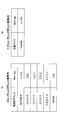
- FIG. FIG. 7 is a diagram illustrating an example of information stored in an application management DB.
- FIG. 4 is a diagram illustrating an example of information stored in an application cache.
- FIG. 7 is a diagram illustrating an example of information stored in a DNS distribution policy management DB.
- FIG. 4 is a diagram illustrating an example of information stored in an IP routing policy management DB and an application routing policy management DB.
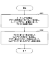
- 5 is a flowchart of management flow control according to the first embodiment. 5 is a flowchart of data flow control according to the first embodiment.
- FIG. 9 is a configuration diagram of a DNS control unit when rewriting a DNS inquiry destination. It is a figure showing an example of information stored in application routing policy management DB at the time of rewriting the address of a DNS inquiry. It is a flowchart of the data flow control in the case of rewriting the address of the inquiry of DNS. 11 is a flowchart in a case where an application cache is updated as needed using a DNS inquiry result.
- FIG. 14 is a diagram illustrating an application cache when the application cache is updated as needed using a DNS inquiry result.
- FIG. 9 is a functional configuration diagram of an access device 100 according to a second embodiment.
- FIG. 4 is a diagram illustrating an example of information stored in an IP routing policy management DB and an application routing policy management DB.
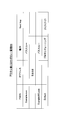
- FIG. 7 is a diagram illustrating an example of information stored in a proxy distribution policy management DB. It is a flow chart of management flow control in a 2nd embodiment. 9 is a flowchart of data flow control according to the second embodiment.
- FIG. 11 is a diagram illustrating an example of information stored in a proxy distribution policy management DB when an application cache is used.
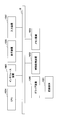
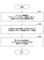
- FIG. 9 is a diagram for explaining a regular update of an application management DB. It is a flowchart of a regular update of an application management DB.
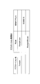
- FIG. 4 is a diagram illustrating an example of information stored in an application cache.
- GeoDNS is an abbreviation for Domain Name System.
- a proxy (which may be referred to as a proxy device or a proxy server) is installed between a user terminal and a SaaS server, and communication is performed via the proxy.
- a proxy device or a proxy server is installed between a user terminal and a SaaS server, and communication is performed via the proxy.
- a large amount of TCP sessions may be consumed at the time of use. Therefore, SaaS may not be used comfortably due to the processing limit of the proxy due to an increase in sessions.
- the existing proxy in order to bypass the proxy for the SaaS traffic, the existing proxy must periodically check the destination of the SaaS communication separately from the SD-WAN device. It must be reflected in the Proxy Auto Configuration (PAC) file, and the PAC file must also be distributed to all end users. Therefore, the operation load may increase.
- PAC Proxy Auto Configuration
- the access device 100 is connected to the closed network 20 and the Internet 30, but this is merely an example. Similar control may be performed between two networks other than the closed network 20 and the Internet 30. Further, the access device 100 may be connected to a plurality of three or more networks and distribute packets to any one of the plurality of networks.
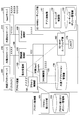
- FIG. 1 shows the overall configuration of a system according to an embodiment of the present invention.
- an access device 100 connected to a user terminal 10, a closed network 20, and the Internet 30 is provided.
- the access device 100 is a device that receives the access from the user terminal 10 and connects the user terminal 10 to a device on the closed network 20 or a device on the Internet 30 to perform communication.
- the access device 100 may be referred to as a SaaS access speed-up device.
- the access device 100 is a device that performs various controls on the data flow, it may be referred to as a control device.
- the closed network 20 is, for example, an intra-company network that connects a plurality of companies.
- the access device 100 is, for example, a device installed at each branch site in a corporate network of a global company.
- a basic configuration of the access device 100 will be described as a first embodiment, and a configuration in which a proxy control unit is added to the access device 100 of the first embodiment will be described as a second embodiment. I do.
- FIG. 2 illustrates a functional configuration diagram of the access device 100 according to the first embodiment.
- the access device 100 includes a command receiving unit 110, a DNS control unit 120, a common application management unit 130, an SD-WAN routing unit 140, and a plurality of IFs (interfaces).
- FIG. 2 shows, as examples of the plurality of IFs, a closed network connection IF 150 for connecting to a closed network, an Internet connection IF 160 for connecting to the Internet, and a LAN-IF 170 for connecting to a LAN. IP addresses are assigned to the closed network connection IF 150 and the Internet connection IF 160 as shown.
- the internal DNS server 210 is connected to the closed network connection IF 150
- the external DNS server 310 and the SaaS server 320 are connected to the Internet connection IF 160
- the user terminal 10 is connected to the LAN-IF 170.
- Each server is assigned an IP address as shown.
- the IP address is not fixed, and changes at any time.
- the IF is not limited to a physical port, but may be a logical port for terminating a tunnel such as IPsec.
- the common application management unit 130 is provided in each access device, but instead, the common application management unit 130 is provided outside the access device 100, and a plurality of access devices are provided. The devices may be installed as commonly available devices. Details of each unit of the access device 100 will be described later.
- the access device 100 may be a system configured by a plurality of computers (including a communication device or the like) or may be a device realized by one computer. Further, the computer may be a physical machine or a virtual machine. Further, access device 100 may be realized by a dedicated hardware circuit that executes the processing described in the present embodiment.
- the access device 100 executes a program corresponding to a process performed by the access device 100 using hardware resources such as a CPU and a memory built in the computer. It can be realized by:
- the above-mentioned program can be recorded on a computer-readable recording medium (a portable memory or the like) and can be stored or distributed. Further, the above program can be provided through a network such as the Internet or electronic mail.
- FIG. 3 is a diagram showing an example of a hardware configuration of the computer.
- the computer in FIG. 3 includes a drive device 1000, an auxiliary storage device 1002, a memory device 1003, a CPU 1004, an interface device 1005, a display device 1006, an input device 1007, and the like, which are interconnected by a bus B.
- the program for realizing the processing in the computer is provided by a recording medium 1001 such as a CD-ROM or a memory card.
- a recording medium 1001 such as a CD-ROM or a memory card.
- the program is installed from the recording medium 1001 to the auxiliary storage device 1002 via the drive device 1000.
- the program need not always be installed from the recording medium 1001, and may be downloaded from another computer via a network.
- the auxiliary storage device 1002 stores installed programs and also stores necessary files and data.
- the memory device 1003 reads the program from the auxiliary storage device 1002 and stores it when there is an instruction to start the program.
- the CPU 1004 implements functions related to the access device 100 according to a program stored in the memory device 1003.
- the interface device 1005 is used as an interface for connecting to a network, and functions as an input unit and an output unit via the network.
- the display device 1006 displays a GUI (Graphical User Interface) or the like by a program.
- the input device 157 includes a keyboard, a mouse, buttons, a touch panel, and the like, and is used to input various operation instructions.
- the common application management unit 130 has an application management DB and an application cache (may be referred to as an application table).
- FIG. 4 shows an example of information stored in the application management DB
- FIG. 5 shows an example of information stored in the application cache.
- the application management DB is a DB that manages various SaaS communication patterns.
- the application management DB has columns such as an application name, an FQDN, and a destination IP address.
- FIG. 4 is an example, and the configuration of the application management DB is not limited to that shown in FIG.
- a destination port number may be included in addition to the application name, FQDN, and destination IP address in FIG.
- other parameters for specifying the SaaS application may be included.
- the destination FQDN is “Example. com or Example 365. com or the destination IP address is B. B. B. This indicates that there are three types of communication patterns, B / B.
- the application cache records the IP address of the SaaS destination server that the access device 100 knows at the moment.
- the application cache columns include, for example, an application name and a destination IP address, but are not limited thereto.
- FIG. 5A shows that the destination IP address whose application name is “Example” is “B. B. B. B shows the case where it is grasped.
- FIG. 5B shows, for example, a case where the destination IP address whose application name is “Example” is “B. B. B. After being recognized as A.B, A.B is set as the destination IP address of “Example”.
- A. A. A shows a case where A is detected.
- the DNS control unit 120 includes a DNS distribution unit 121 and a DNS distribution policy management unit 122.
- the DNS allocation unit 121 allocates a DNS inquiry (may be referred to as a DNS inquiry packet) according to a DNS allocation policy managed by the DNS allocation policy management unit 122. That is, the destination of the DNS inquiry is determined according to the DNS distribution policy, and the DNS inquiry is transmitted to the destination.
- a DNS inquiry packet may be referred to as a DNS inquiry packet
- the DNS assignment policy management unit 122 has a DNS assignment policy management DB shown in FIG.
- the DNS distribution policy management DB is a DB that stores information that defines operations to be performed in response to a DNS inquiry.
- FIG. com or Example 365. com in response to a DNS query including the FQDN of Y. Y. Y forwards to the external DNS server 310 and other inquiries define an operation of forwarding to the internal DNS server 210 as Default.
- the SD-WAN routing unit 140 includes an application detection unit 141, a routing control unit 142, and a routing policy management unit 143.
- the application detection 141 checks the data flow routed by the SD-WAN routing unit 140 (more specifically, the packets constituting the data flow) to detect the destination or source application of the data flow.
- the routing control unit 142 executes packet routing according to the routing policy managed by the routing policy management unit 143.
- the routing policy management unit 143 has an IP routing policy management DB and an application routing policy management DB.
- FIG. 7A shows an example of information stored in the IP routing policy management DB
- FIG. 7B shows an example of information stored in the application routing policy management DB.
- the $ IP routing policy management DB corresponds to a routing table of a normal router, and stores a destination IP address and Next @ Hop as shown in FIG.
- the application routing policy management DB is a database that stores information that defines a routing control method for a target application.
- FIG. 7B shows, as an example, information that defines a routing operation for transferring the SaaS flow of the target application “Example” to a local Next @ hop (Internet connection IF (JJJJ)). ing.
- FIG. 7A shows that the IP routing policy management DB has a destination IP address and a Next @ hop column
- FIG. 7B shows that the application routing policy management DB has a target application and a Next @ hop column. Although shown, these are examples.
- Each of the IP routing policy management DB and the application routing policy management DB may include a communication source IP address and a port number.
- control of a management flow operations for setting / updating a DB
- control of a data flow operations when the user terminal 10 performs communication
- Target designation The instruction receiving unit 110 receives designation of a target SaaS to be subjected to Local Breakout from the user, and instructs the DNS control unit 120 and the SD-WAN routing unit 140 based on the received content.
- the DNS control unit 120 collects information necessary for Local Breakout for the target SaaS from the common application management unit 130, and updates the DNS distribution policy management DB (for example, FIG. 6). .
- the information required for the Local Breakout for the target SaaS is, for example, one or more FQDNs (FQDN list) corresponding to the target SaaS.
- the DNS control unit 120 associates the FQDN in the acquired FQDN list with the assumed operation, and stores the FQDN in the DNS distribution policy management DB.
- the Next-hop at the time of Local Breakout is assumed to be the IP address (YYYYY) of the external DNS server 310 set in advance. Inquiries about other FQDNs assume the IP address (XXXXX) of the internal DNS server 210.
- the FQDN of the target SaaS in the DNS inquiry is “Example. com, information corresponding to the operation of forwarding the DNS inquiry to the IP address (YYYY) is recorded.
- the SD-WAN routing unit 140 updates the application routing policy management DB (for example, FIG. 7B). Specifically, as shown in FIG. 7B, information in which the target SaaS is associated with a predefined Next hop address is recorded.
- Example 1 of data flow control Next, the operation of the access device 100 in the data flow control example 1 will be described along the procedure of the flowchart in FIG.
- the address of the DNS server in the user terminal 10 is set in the DNS control unit 120 (ZZZZ) of the access device 100.
- the routing control unit 142 receives the DNS query transmitted from the user terminal 10, and, in accordance with the IP routing policy management DB (eg, FIG. 7A), performs the same operation as a normal router.
- the corresponding inquiry is transferred to the DNS control unit 120.
- the DNS distribution unit 121 of the DNS control unit 120 receives the DNS inquiry.
- DNS query retransfers The DNS distribution unit 121 in the DNS control unit 120 retransfers the received DNS query in accordance with the DNS distribution policy management DB (eg, FIG. 6).
- the DNS allocation unit 121 transfers the DNS inquiry to the external DNS server 310 (YYYY) according to the DNS allocation policy management DB (FIG. 6). Other DNS queries are forwarded to the internal DNS server 210 according to Default.
- the destination of the DNS inquiry may be changed to the transfer destination IP address by providing the inquiry destination change unit 123 described later.
- the user terminal 10 receives the IP address sent from the DNS server and starts data communication with the IP address as a destination.
- the application detection unit 141 of the SD-WAN routing unit 140 detects a specific SaaS data flow, and updates an application cache (eg, FIG. 5) using the destination IP address of the flow.
- an application cache eg, FIG. 5
- As a method of detecting the SaaS data flow by the application detection unit 141 for example, there is a method of extracting from the HTTP / HTTPs Header, but the method is not limited thereto.
- the routing control unit 142 controls the routing of the SaaS data flow using the application routing policy management DB (for example, FIG. 7B) and the application cache (for example, FIG. 5). For example, if the target SaaS is Example. com in the application cache. com as the destination address for A. A. After A is recorded, the routing control unit 142 determines that the destination is A.A. A. A. When the packet A is received, the target SaaS is understood to be “Example” by referring to the application cache, and the packet is transferred to the Internet connection IF 160 (JJJJ) by referring to the application routing policy management DB. .J).
- the DNS control unit 120 includes an inquiry destination change unit 123 in addition to the DNS allocation unit 121 and the DNS allocation policy management unit 122.
- a routing policy for a DNS inquiry is newly added to the application routing policy management DB.
- This routing policy is a policy in which DNS inquiry traffic is specified by a port number (eg, 53) and Next @ hop is set to the DNS control unit 120 (ZZZZ).
- the routing control unit 142 Upon receiving the DNS inquiry, the routing control unit 142 transmits the DNS inquiry to the DNS control unit 120 (ZZZZ) in accordance with the DNS-related policy in the application routing policy management DB (FIG. 11). ).
- DNS Query Retransfer The DNS distribution unit 121 of the DNS control unit 120 retransmits the received DNS inquiry according to the DNS distribution policy management unit 122. Inquiries other than the target SaaS are re-transferred to the internal DNS server 210 (XXXX) according to the default.
- the application detection unit 141 analyzes the packet to identify the SaaS application corresponding to the data flow relating to the packet, and updates the application cache (for example, FIG. 5).
- the application cache may be updated using the result of the DNS inquiry.
- the SaaS application can be identified by First @ packet.
- a DNS inquiry is transferred to the external DNS server 310, and the routing control unit 142 receives an inquiry result (an IP address corresponding to FQDN) sent from the external DNS server 310.
- the routing control unit 142 updates the application cache using the result of the inquiry.
- Example. com query result is A. A. A. A
- Example 365. com is C.com. C. C. C
- the routing control unit 142 receives the respective query results, the application cache is updated as shown in FIG. That is, A. A. A. A record and C.A. C. C. The record of C is added.
- Example. com and Example 365. All of the application names of “com” are identified as “Example”.
- Routing Control Thereafter, when the routing control unit 142 receives the data flow of the corresponding SaaS, the routing control unit 142 uses the application routing policy management DB (for example, FIG. 7B) and the application cache (for example, FIG. 14). Controls the routing of the flow.
- the application routing policy management DB for example, FIG. 7B
- the application cache for example, FIG. 14
- the routing control unit 142 searches the application cache using the destination IP address of the data flow, and if there is a record that hits, the routing control unit 142 uses the application name (target SaaS name) of the record to search the application routing policy management DB. Next @ hop of the target SaaS is searched. As a result, the routing control unit 142 transfers the flow to the IP address described in Next @ hop.
- FIG. 15 illustrates a functional configuration diagram of the access device 100 according to the second embodiment.
- the access device 100 according to the second embodiment has a configuration in which a proxy control unit 180 is added to the access device 100 according to the first embodiment.
- FIG. 15 shows the internal proxy server 220.
- the IP address of the proxy control unit 180 is Z ′. Z '. Z '. Z ', and the IP address of the internal proxy server 220 is Z1. Z1. Z1. Z1.
- the proxy control unit 180 has a proxy distribution unit 181 and a proxy distribution policy management unit 182.
- the proxy assignment policy management unit 182 has a proxy assignment policy management DB.
- FIG. 17 shows an example of information stored in the proxy distribution policy management DB.
- the proxy distribution policy management DB is a DB that stores information defining each FQDN and a proxy control operation for an IP address.
- the proxy distribution unit 181 performs traffic distribution control according to the information of the proxy distribution policy management DB. For example, the proxy distribution unit 181 determines that the destination FQDN is “Example. When a packet that is “com” is received, the packet is made to be a proxy pass-through. In the case of Default, proxy chaining is performed with the internal proxy (Z1.Z1.Z1.Z1).
- the instruction receiving unit 110 receives the specification of the target SaaS to be subjected to Local Breakout from the user, and instructs the proxy control unit 180 based on the received content.
- the proxy control unit 180 collects information necessary for Local Breakout for the target SaaS from the application management DB of the common application management unit 130, and updates the proxy distribution policy management DB.
- the information required for the Local Breakout for the target SaaS is, for example, one or more FQDNs (FQDN list) and one or more IP addresses (IP address list) corresponding to the target SaaS.
- the proxy control unit 180 associates the obtained FQDN list and the IP address list with the expected operation, and stores the list in the proxy distribution policy management DB.
- Next-hop in the case where no pass-through is performed is the IP address (Z1.Z1.Z1.Z1) of the internal DNS server 220 that is the destination of the proxy chain set in advance. .
- the routing control unit 142 receives traffic for the proxy control unit 180 (here, a SaaS access request), and stores the IP routing policy management DB of the routing policy management unit 143 (for example, FIG. According to a)), the traffic is transferred to the proxy control unit 180 (Z'.Z'.Z'.Z ').
- the proxy distribution unit 181 in the proxy control unit 180 receives the traffic (SaaS access request).
- the proxy distribution unit 181 temporarily terminates the received SaaS access request, and performs proxy control for accessing the corresponding SaaS in accordance with the proxy distribution policy management DB (FIG. 17).
- Example. com is passed through according to the operation definition of FIG.
- the proxy control unit 180 is used as a starting point to execute a DNS inquiry.
- the DNS inquiry operation and a series of subsequent operations are the same as those described above.
- the DNS inquiry is sent from the proxy control unit 180 to the routing control unit 142, and sent from the routing control unit 140 to the DNS control unit 120.
- the proxy control unit 180 requests the internal proxy server 220 to access the data flow in order to chain the data flow to the internal proxy server 220.
- the following format is considered as an example of the contents of the request.
- the proxy control unit 180 collects necessary information from the application management DB of the common application management unit 130, but in addition to (or instead of) collecting information from the application cache. It may be.
- FIG. 20 shows an example of the proxy distribution policy management DB 182 updated using information collected from the application cache.
- the proxy control unit 180 collects not only the FQDN list and the IP address corresponding to the target SaaS from the application management DB, but also the already cached IP addresses from the application cache, and assigns those IP addresses to the proxy distribution policy management. Link with the operation assumed in the DB. Further, the proxy distribution policy management unit 182 periodically synchronizes with the common application management unit 130, and always holds the latest information of the application management DB and the application cache.
- the operation based on the correct IP address can be executed by holding the latest information in the application cache as described above.
- the common application management unit 130 periodically inquires (polls) whether the external application management server 400 has a DB update.
- the common application management unit 130 may periodically update the application cache.
- the application cache holds a timer value for each record.
- the common application management unit 130 monitors the application cache and automatically deletes the record when the time of the timer value elapses without being updated from the time when the data of the record is set.
- the DNS control unit 120 follows the control of the data flow of the specific SaaS while referring to the common application management unit 130, and determines and controls the optimal exit of the DNS traffic related thereto.
- the proxy control unit 180 performs routing control so as to bypass the existing proxy for the data flow of the specific SaaS while referring to the common application management unit 130.
- the IP address of the SaaS server which is the result of the DNS inquiry performed via the DNS control unit 120, is reflected in the application cache as needed, and the specific SaaS can be identified using the SaaS server IP of the access destination. .
- the specific SaaS can be identified by First @ Packet using the latest DNS inquiry result.
- a control device that is connected to a plurality of networks and distributes a packet received from a user terminal to one of the plurality of networks, A DNS control unit that receives a DNS inquiry packet transmitted from the user terminal, and distributes the DNS inquiry packet to one of the plurality of networks based on an inquiry target of the DNS inquiry packet; A routing unit that receives a packet, determines a destination of the packet based on a destination address of the packet, and transmits the packet to the determined destination.
- the control device includes an application table that stores information that associates a destination address of a packet with an application of a destination of the packet, The routing unit recognizes an application corresponding to a destination address of the received packet by referring to the application table, and routes the packet to any one of the plurality of networks according to a policy predetermined for the application.
- the control device according to claim 1 wherein the control device distributes the data to the net.
- the routing unit updates the application table using an inquiry target of the DNS inquiry packet and an address received as a response to the inquiry. (Section 4) 4.
- the control device has a timer value for each record, and deletes a record whose timer value period has elapsed. 5.
- the control device according to any one of claims 1 to 4, wherein the DNS control unit rewrites a destination address of the DNS inquiry packet according to a destination of the DNS inquiry packet.
- the control device is connected to a predetermined proxy device, the control device, The control according to any one of claims 1 to 5, further comprising: a proxy control unit that determines whether to transmit the packet to the proxy device based on an application to which the received packet is accessed. apparatus.
- the proxy control unit Providing a proxy distribution table that records destination addresses and operations for each application, and by referring to the proxy distribution table, determines whether to transmit a packet to the proxy device, The control device according to claim 6, wherein the control device updates the proxy distribution table using the application table.
- the control device includes: An application management database that manages application information; The control device according to any one of claims 1 to 7, further comprising: a management unit that updates the application management database by periodically accessing an external application management server.
- (Section 9) A control method executed by a control device that is connected to a plurality of networks and distributes a packet received from a user terminal to one of the plurality of networks, Receiving a DNS inquiry packet transmitted from the user terminal, and distributing the DNS inquiry packet to one of the plurality of networks based on an inquiry target of the DNS inquiry packet; Receiving the packet, determining the destination of the packet based on the destination address of the packet, and transmitting the packet to the determined destination.
- (Section 10) A program for causing a computer to function as each section in the control device according to any one of the first to eighth aspects.
- Reference Signs List 10 User terminal 20 Closed network 30 Internet 100 Access device 110 Command receiving unit 120 DNS control unit 121 DNS distribution unit 122 DNS distribution policy management unit 123 Inquiry destination change unit 130 Common application management unit 140 SD-WAN routing unit 141 Application detection unit 142 Routing control unit 143 Routing policy management unit 150 Closed network connection IF 160 Internet connection IF 170 LAN-IF 180 Proxy control unit 181 Proxy distribution unit 182 Proxy distribution policy management unit 210 Internal DNS server 220 Internal proxy server 310 External DNS server 320 SaaS server 400 External application management server 1000 Drive device 1001 Recording medium 1002 Auxiliary storage device 1003 Memory device 1004 CPU 1005 Interface device 1006 Display device 1007 Input device
Landscapes
- Engineering & Computer Science (AREA)
- Computer Networks & Wireless Communication (AREA)
- Signal Processing (AREA)
- Data Exchanges In Wide-Area Networks (AREA)
Abstract
複数の網に接続され、ユーザ端末から受信したパケットを当該複数の網のうちのいずれかの網に振り分ける制御装置において、前記ユーザ端末から送信されたDNS問い合わせパケットを受信し、当該DNS問い合わせパケットの問い合わせ対象に基づいて、当該DNS問い合わせパケットを前記複数の網のうちのいずれかの網に振り分けるDNS制御部と、パケットを受信し、当該パケットの宛先アドレスに基づいて当該パケットの送信先を決定し、決定された送信先に当該パケットを送信するルーティング部とを備える。
Description
本発明は、ユーザ端末からネットワーク上のサーバなどへのアクセスを高速化する技術に関連するものである。
近年、Software-as-a-Service(SaaS)の利用が爆発的に普及してきた。一方、SaaSでは、元々LAN環境での利用を想定して設計されていたアプリケーションがCloud上で提供されるため、そのパフォーマンスはネットワークの遅延や品質に左右され、特に企業がグローバル展開するほどネットワークの遅延や品質の影響が大きくなる。
現状では、閉域網である企業ネットワークはSaaS利用に向けて設計されていない。例えば、多くの企業ネットワークではインターネットへの接続点は限られているので、インターネットを経由するSaaS接続が遠回りになってしまう。
また、企業ネットワーク内の通信である拠点間の通信とSaaS向けの通信とを同一回線に重畳する場合、拠点間などで回線の帯域が圧迫される。2020年ごろには半分以上の企業がネットワークに関連するSaaS利用上の問題を抱えるという予測もある。
北米の大手金融/流通/小売りなどの企業のIT責任者を中心に立ち上げたONUG(Open Networking User Group)という団体でSD-WAN(Software-defined WAN)の技術が提唱されてきた。現在のWANコストの削減、運用の簡略化、品質の向上などを狙い、多くの企業が市販のSD-WANソリューションを導入し始めた。SD-WANの利用において、一番有望視されているユースケースがSaaSアクセスを中心としたLocal Breakoutと言われている。
Local Breakoutとは、ブランチ拠点において、SaaSにアクセスする際に、特定のデータフローをDeep Packet Inspection(DPI)エンジンを用いて識別し、識別された該当データフローをブランチ拠点からインターネットに直接流すようにルーティングを制御する仕組みである。
SD-WAN Customer Premises Equipment(CPE)の利用により、Local Breakoutを実現し、SaaS向けのトラフィックをブランチ拠点からインターネットに直接流すことによって、上記の様々な問題の解決が期待されている。
しかし、従来のSD-WAN技術を用いたSaaSアクセス方法は実際の利用シーンに最適化されていない場合が多いため、ユーザ端末からSaaSサーバへのアクセスに遅延が生じるなどの課題がある。
本発明は上記の点に鑑みてなされたものであり、閉域網を介した通信を行うユーザ端末が、インターネット上の所定のサーバに高速にアクセスすることを可能とする技術を提供することを目的とする。
開示の技術によれば、複数の網に接続され、ユーザ端末から受信したパケットを当該複数の網のうちのいずれかの網に振り分ける制御装置であって、
前記ユーザ端末から送信されたDNS問い合わせパケットを受信し、当該DNS問い合わせパケットの問い合わせ対象に基づいて、当該DNS問い合わせパケットを前記複数の網のうちのいずれかの網に振り分けるDNS制御部と、
パケットを受信し、当該パケットの宛先アドレスに基づいて当該パケットの送信先を決定し、決定された送信先に当該パケットを送信するルーティング部と
を備える制御装置が提供される。
前記ユーザ端末から送信されたDNS問い合わせパケットを受信し、当該DNS問い合わせパケットの問い合わせ対象に基づいて、当該DNS問い合わせパケットを前記複数の網のうちのいずれかの網に振り分けるDNS制御部と、
パケットを受信し、当該パケットの宛先アドレスに基づいて当該パケットの送信先を決定し、決定された送信先に当該パケットを送信するルーティング部と
を備える制御装置が提供される。
開示の技術によれば、閉域網を介した通信を行うユーザ端末が、インターネット上の所定のサーバに高速にアクセスすることを可能とする技術が提供される。
以下、図面を参照して本発明の実施形態を説明する。以下で説明する実施形態は一例に過ぎず、本発明が適用される実施の形態は、以下の実施形態に限られるわけではない。
(課題について)
まず、実施の形態で説明するアクセス装置100により解決される課題について説明する。なお、以下の3つの課題は例であり、アクセス装置100により解決される課題は下記の課題に限られない。
まず、実施の形態で説明するアクセス装置100により解決される課題について説明する。なお、以下の3つの課題は例であり、アクセス装置100により解決される課題は下記の課題に限られない。
(1)DNSについての課題
多くのSaaSはどの地域のユーザにも最大限のパフォーマンスでサービスを提供するため、GeoDNS技術を採用している。GeoDNSの利用により、DNSサーバに問い合わせたクライアントの物理的な位置に応じて、最寄りのSaaSのサーバのIPアドレスを応答することができる。なお、DNSはDomain Name Systemの略である。
多くのSaaSはどの地域のユーザにも最大限のパフォーマンスでサービスを提供するため、GeoDNS技術を採用している。GeoDNSの利用により、DNSサーバに問い合わせたクライアントの物理的な位置に応じて、最寄りのSaaSのサーバのIPアドレスを応答することができる。なお、DNSはDomain Name Systemの略である。
ただし、企業ユーザがデータセンタなどの主要拠点に内部DNSサーバを設置し、外部DNSサーバへの問い合わせを当該主要拠点からブレークアウトさせている設計が多い。そのため、SaaSアクセスに関するDNSトラフィックは、データセンタなどの主要拠点からインターネットに出るの対し、データフローはブランチ拠点(例:データセンタと異なる国に設置された拠点)からインターネットに出ることになり、両者の出口が合致していない。その結果、せっかくSaaSに関する特定のデータフローをブランチ拠点にてブレークアウトしているのに、主要拠点からDNS問い合わせをした結果、主要拠点の最寄りのSaaSサーバにアクセスしてしまい、期待されている遅延の改善効果が見られない場合がある。
(2)プロキシについての課題
ユーザ端末とSaaSサーバとの間にプロキシ(プロキシ装置、プロキシサーバなどと称してもよい)を設置して、プロキシを経由して通信を行うことが多い。しかし、SaaSの種類によって、利用時にTCPセッションを大量に消費する場合もあるため、セッション増によるプロキシの処理限界により、SaaSが快適に利用できないことがある。
ユーザ端末とSaaSサーバとの間にプロキシ(プロキシ装置、プロキシサーバなどと称してもよい)を設置して、プロキシを経由して通信を行うことが多い。しかし、SaaSの種類によって、利用時にTCPセッションを大量に消費する場合もあるため、セッション増によるプロキシの処理限界により、SaaSが快適に利用できないことがある。
そこで、既存のプロキシをバイパスし、処理負荷を軽減することが求められている。従来方式では、SaaSトラフィックに対して、プロキシをバイパスさせるために、SD-WAN装置とは別に、既存のプロキシにおいて、SaaS向けの通信の宛先を定期的にチェックしなければならず、その結果をプロキシ自動設定(PAC)ファイルに反映し、当該PACファイルをまたすべてのエンドユーザに配布しなければならない。従って、運用負荷が増加する場合がある。
(3)パケット識別遅延の課題
また、従来のSD-WAN装置のDPIエンジンにおいて、HTTP/HTTPsのハンドシェイクのやり取りを解析し、その中で抽出したSaaSのドメインネームを用いてアクセス先のSaaSを判別する方法が採用されている。しかし、この方法では最初に到着したパケット(First Packet)にてSaaSを識別することが困難であるため、該当SaaSの最初のフローが主要拠点から出てしまう場合がある。
また、従来のSD-WAN装置のDPIエンジンにおいて、HTTP/HTTPsのハンドシェイクのやり取りを解析し、その中で抽出したSaaSのドメインネームを用いてアクセス先のSaaSを判別する方法が採用されている。しかし、この方法では最初に到着したパケット(First Packet)にてSaaSを識別することが困難であるため、該当SaaSの最初のフローが主要拠点から出てしまう場合がある。
以下、本発明の実施の形態として、上記課題を解決する技術について詳細に説明する。なお、本実施の形態では、アクセス装置100が閉域網20、及びインターネット30に接続されるが、この形態は一例に過ぎない。閉域網20及びインターネット30以外の2網間で同様の制御がされてもよい。また、アクセス装置100は3つ以上の複数の網に接続されて、パケットを当該複数の網のうちのいずれかの網に振り分けることとしてもよい。
(システム構成)
図1に本発明の実施の形態におけるシステムの全体構成を示す。図1に示すとおり、ユーザ端末10、閉域網20、及びインターネット30と接続されるアクセス装置100が備えられる。アクセス装置100は、ユーザ端末10からのアクセスを受けて、ユーザ端末10を、閉域網20上の装置、あるいは、インターネット30上の装置に接続させ、通信を行う装置である。なお、アクセス装置100を、SaaSアクセス高速化装置と称してもよい。また、アクセス装置100は、データフローに対する種々の制御を実施する装置なので、これを制御装置と称してもよい。
図1に本発明の実施の形態におけるシステムの全体構成を示す。図1に示すとおり、ユーザ端末10、閉域網20、及びインターネット30と接続されるアクセス装置100が備えられる。アクセス装置100は、ユーザ端末10からのアクセスを受けて、ユーザ端末10を、閉域網20上の装置、あるいは、インターネット30上の装置に接続させ、通信を行う装置である。なお、アクセス装置100を、SaaSアクセス高速化装置と称してもよい。また、アクセス装置100は、データフローに対する種々の制御を実施する装置なので、これを制御装置と称してもよい。
閉域網20は、例えば企業の複数拠点を接続する企業内の網である。アクセス装置100は、例えば、グローバル企業の企業ネットワークにおけるブランチ拠点毎に設置される装置である。
以下、アクセス装置100の構成と動作を詳細に説明する。以下では、アクセス装置100の基本的な構成を第1の実施の形態として説明し、第1の実施の形態のアクセス装置100にプロキシ制御部が追加された構成を第2の実施の形態として説明する。
(第1の実施の形態)
<装置構成>
図2に、第1の実施の形態におけるアクセス装置100の機能構成図を示す。図2に示すように、アクセス装置100は、指令受信部110、DNS制御部120、共通アプリケーション管理部130、SD-WANルーティング部140、複数のIF(インタフェース)を有する。
<装置構成>
図2に、第1の実施の形態におけるアクセス装置100の機能構成図を示す。図2に示すように、アクセス装置100は、指令受信部110、DNS制御部120、共通アプリケーション管理部130、SD-WANルーティング部140、複数のIF(インタフェース)を有する。
複数のIFの例として、図2には、閉域網に接続するための閉域網接続IF150、インターネットに接続するためのInternet接続IF160、LANに接続するためのLAN-IF170が示されている。閉域網接続IF150及びInternet接続IF160には図示のとおりにIPアドレスが割り当てられている。
図示のとおり、閉域網接続IF150には内部DNSサーバ210が接続され、Internet接続IF160には、外部DNSサーバ310及びSaaSサーバ320が接続され、LAN-IF170にはユーザ端末10が接続されている。また、各サーバには図示のとおりのIPアドレスが割り当てられている。本実施の形態におけるSaaSサーバ320に関して、IPアドレスは固定ではなく、随時IPアドレスが変わる。
なお、IFは、物理ポートに限らず、IPsecなどのトンネルを終端する論理ポートであってもよい。また、本実施の形態では、例として、共通アプリケーション管理部130を各アクセス装置に備えることとしているが、これに代えて、共通アプリケーション管理部130を、アクセス装置100の外部に備え、複数のアクセス装置が共通に利用可能なものとして設置してもよい。アクセス装置100の各部の詳細については後述する。
アクセス装置100は、複数のコンピュータ(通信装置なども含む)により構成されるシステムであってもよいし、1つのコンピュータで実現される装置であってもよい。また、当該コンピュータは物理マシンであってもよいし仮想マシンであってもよい。また、アクセス装置100が、本実施の形態で説明する処理を実行する専用ハードウェア回路で実現されてもよい。
アクセス装置100がコンピュータで実現される場合において、アクセス装置100は、コンピュータに内蔵されるCPUやメモリ等のハードウェア資源を用いて、アクセス装置100で実施される処理に対応するプログラムを実行することによって実現することが可能である。上記プログラムは、コンピュータが読み取り可能な記録媒体(可搬メモリ等)に記録して、保存したり、配布したりすることが可能である。また、上記プログラムをインターネットや電子メール等、ネットワークを通して提供することも可能である。
図3は、上記コンピュータのハードウェア構成例を示す図である。図3のコンピュータは、それぞれバスBで相互に接続されているドライブ装置1000、補助記憶装置1002、メモリ装置1003、CPU1004、インタフェース装置1005、表示装置1006、及び入力装置1007等を有する。
当該コンピュータでの処理を実現するプログラムは、例えば、CD-ROM又はメモリカード等の記録媒体1001によって提供される。プログラムを記憶した記録媒体1001がドライブ装置1000にセットされると、プログラムが記録媒体1001からドライブ装置1000を介して補助記憶装置1002にインストールされる。但し、プログラムのインストールは必ずしも記録媒体1001より行う必要はなく、ネットワークを介して他のコンピュータよりダウンロードするようにしてもよい。補助記憶装置1002は、インストールされたプログラムを格納すると共に、必要なファイルやデータ等を格納する。
メモリ装置1003は、プログラムの起動指示があった場合に、補助記憶装置1002からプログラムを読み出して格納する。CPU1004は、メモリ装置1003に格納されたプログラムに従って、アクセス装置100に係る機能を実現する。インタフェース装置1005は、ネットワークに接続するためのインタフェースとして用いられ、ネットワークを介した入力手段及び出力手段として機能する。表示装置1006はプログラムによるGUI(Graphical User Interface)等を表示する。入力装置157はキーボード及びマウス、ボタン、又はタッチパネル等で構成され、様々な操作指示を入力させるために用いられる。
以下、アクセス装置100の各部の構成、動作を詳細に説明する。
<共通アプリケーション管理部130>
共通アプリケーション管理部130は、アプリケーション管理DBとアプリケーションキャッシュ(アプリケーションテーブルと称してもよい)を有する。図4に、アプリケーション管理DBに格納される情報の例を示し、図5に、アプリケーションキャッシュに格納される情報の例を示す。
共通アプリケーション管理部130は、アプリケーション管理DBとアプリケーションキャッシュ(アプリケーションテーブルと称してもよい)を有する。図4に、アプリケーション管理DBに格納される情報の例を示し、図5に、アプリケーションキャッシュに格納される情報の例を示す。
アプリケーション管理DBは様々なSaaSの通信パターンを管理するDBであり、図4に示す例では、アプリケーション管理DBのカラムとして、アプリケーション名、FQDN、宛先IPアドレスなどを有する。図4は例であり、アプリケーション管理DBの構成は図4に示すものに限られない。例えば、図4のアプリケーション名、FQDN、宛先IPアドレスに加えて、宛先ポート番号を含めてもよい。また、SaaSアプリを特定するその他のパラメータを含めてもよい。
図4に示す情報は、アプリケーション名が「Example」のSaaSに関しては、宛先のFQDNがExample.comもしくは、Example365.comもしくは、宛先IPアドレスがB.B.B.B/Bの3種類の通信パターンがあることを示す。
アプリケーションキャッシュは、現時点においてアクセス装置100が把握しているSaaSの宛先サーバのIPアドレスを記録する。図5に示すように、アプリケーションキャッシュのカラムとしては、例えば、アプリケーション名と宛先IPアドレスを有するが、これに限られるわけではない。また、図5(a)は、アプリケーション名が「Example」の宛先IPアドレスがB.B.B.Bとして把握された場合を示している。図5(b)は、例えば、アプリケーション名が「Example」の宛先IPアドレスがB.B.B.Bとして把握された後、「Example」の宛先IPアドレスとしてA.A.A.Aが検知された場合を示している。
<DNS制御部120>
図2に示したように、DNS制御部120は、DNS振り分け部121とDNS振り分けポリシー管理部122を有する。
図2に示したように、DNS制御部120は、DNS振り分け部121とDNS振り分けポリシー管理部122を有する。
DNS振り分け部121は、DNS振り分けポリシー管理部122が管理するDNS振り分けポリシーに従って、DNS問い合わせ(DNS問い合わせパケットと称してもよい)を振り分ける。つまり、当該DNS振り分けポリシーに従って、DNS問い合わせの送信先を決定し、その送信先に向けてDNS問い合わせを送信する。
DNS振り分けポリシー管理部122は、図6に示すDNS振り分けポリシー管理DBを有する。DNS振り分けポリシー管理DBは、DNS問い合わせに対して、実行する動作を定義する情報を格納するDBである。図6に示す例では、Example.comあるいはExample365.comのFQDNが含まれるDNS問い合わせに対して、IPアドレスがY.Y.Y.Yの外部DNSサーバ310にForwardし、その他の問い合わせは、Defaultとして内部DNSサーバ210にForwardする動作を定義している。
<SD-WANルーティング部140>
図2に示したように、SD-WANルーティング部140は、アプリ検知部141、ルーティング制御部142、ルーティングポリシー管理部143を有する。
図2に示したように、SD-WANルーティング部140は、アプリ検知部141、ルーティング制御部142、ルーティングポリシー管理部143を有する。
アプリ検知141は、SD-WANルーティング部140によりルーティングされるデータフロー(より詳細にはデータフローを構成するパケット)を調べることにより、そのデータフローの宛先あるいは送信元のアプリケーションを検知する。ルーティング制御部142は、ルーティングポリシー管理部143に管理されているルーティングポリシーに従ってパケットのルーティングを実行する。
ルーティングポリシー管理部143は、IPルーティングポリシー管理DBとアプリルーティングポリシー管理DBとを有する。図7(a)に、IPルーティングポリシー管理DBに格納される情報の例を示し、図7(b)に、アプリルーティングポリシー管理DBに格納される情報の例を示す。
IPルーティングポリシー管理DBは、通常のルータのルーティングテーブルに相当し、図7(a)に示すとおり、宛先IPアドレスとNext Hopを格納している。
アプリルーティングポリシー管理DBは対象アプリに対するルーティング制御方法を定義する情報を格納するDBである。図7(b)には、一例として対象アプリ「Example」のSaaSフローをローカルにあるNext hop(Internet接続IF(J.J.J.J))に転送するルーティング動作を定義する情報が示されている。
図7(a)はIPルーティングポリシー管理DBが宛先IPアドレスとNext hopのカラムを有することを示し、図7(b)はアプリルーティングポリシー管理DBが対象アプリと、Next hopのカラムを有することを示しているが、これらは一例である。IPルーティングポリシー管理DBとアプリルーティングポリシー管理DBのそれぞれにおいて、通信元のIPアドレスや、ポート番号などを含めてもよい。
以下、アクセス装置100の基本的な動作として、DBの設定/更新などのための動作(マネジメントフローの制御と呼ぶ)と、ユーザ端末10が通信を行う際の動作(データフローの制御と呼ぶ)について説明する。
<マネジメントフローの制御>
図8に示すフローチャートの手順に沿ってマネジメントフローの制御におけるアクセス装置100の動作について説明する。
図8に示すフローチャートの手順に沿ってマネジメントフローの制御におけるアクセス装置100の動作について説明する。
S101)対象指定
指示受信部110は、ユーザからLocal breakoutさせる対象SaaSの指定を受信し、受信内容に基づいてDNS制御部120と、SD-WANルーティング部140にそれぞれ指示をする。
指示受信部110は、ユーザからLocal breakoutさせる対象SaaSの指定を受信し、受信内容に基づいてDNS制御部120と、SD-WANルーティング部140にそれぞれ指示をする。
S102)DNS振り分けポリシー管理DB更新
DNS制御部120は、共通アプリケーション管理部130から、対象SaaSに対するLocal breakoutのために必要な情報を収集し、DNS振り分けポリシー管理DB(例:図6)を更新する。
DNS制御部120は、共通アプリケーション管理部130から、対象SaaSに対するLocal breakoutのために必要な情報を収集し、DNS振り分けポリシー管理DB(例:図6)を更新する。
対象SaaSに対するLocal breakoutのために必要な情報は、例えば、対象SaaSに対応する1つ又は複数のFQDN(FQDN一覧)である。DNS制御部120は、取得したFQDN一覧におけるFQDNを想定される動作と紐付け、DNS振り分けポリシー管理DBに格納する。
本実施の形態では、Local breakoutの際のNext-hopは事前に設定された外部DNSサーバ310のIPアドレス(Y.Y.Y.Y)を想定する。それ以外のFQDNに関する問い合わせは内部DNSサーバ210のIPアドレス(X.X.X.X)を想定する。
例えば、図6の最初のレコードには、DNS問い合わせにおける対象SaaSのFQDNがExample.comである場合において、当該DNS問い合わせをIPアドレス(Y.Y.Y.Y)にFowardする動作に対応する情報が記録される。
S103)アプリルーティングポリシー管理DB更新
SD-WANルーティング部140は、アプリルーティングポリシー管理DB(例:図7(b))を更新する。具体的には、図7(b)に示すように、対象SaaSと事前に定義されているNext hopアドレスとを紐付けた情報を記録する。
SD-WANルーティング部140は、アプリルーティングポリシー管理DB(例:図7(b))を更新する。具体的には、図7(b)に示すように、対象SaaSと事前に定義されているNext hopアドレスとを紐付けた情報を記録する。
<データフローの制御例1>
次に、データフローの制御例1におけるアクセス装置100の動作について、図9のフローチャートの手順に沿って説明する。データフローの制御例1では、ユーザ端末10でのDNSサーバのアドレスがアクセス装置100のDNS制御部120(Z.Z.Z.Z)に設定されている。
次に、データフローの制御例1におけるアクセス装置100の動作について、図9のフローチャートの手順に沿って説明する。データフローの制御例1では、ユーザ端末10でのDNSサーバのアドレスがアクセス装置100のDNS制御部120(Z.Z.Z.Z)に設定されている。
S201)DNS問い合わせ受信/転送
ルーティング制御部142は、ユーザ端末10から送信されたDNS問い合わせを受信し、IPルーティングポリシー管理DB(例:図7(a))に従って、通常のルータと同様にして、該当問い合わせをDNS制御部120に転送する。DNS制御部120のDNS振り分け部121がDNS問い合わせを受信する。
ルーティング制御部142は、ユーザ端末10から送信されたDNS問い合わせを受信し、IPルーティングポリシー管理DB(例:図7(a))に従って、通常のルータと同様にして、該当問い合わせをDNS制御部120に転送する。DNS制御部120のDNS振り分け部121がDNS問い合わせを受信する。
S202)DNS問い合わせ再転送
DNS制御部120におけるDNS振り分け部121は、受信したDNS問い合わせをDNS振り分けポリシー管理DB(例:図6)に従って再転送する。
DNS制御部120におけるDNS振り分け部121は、受信したDNS問い合わせをDNS振り分けポリシー管理DB(例:図6)に従って再転送する。
例えば、該当DNS問い合わせに含まれるFQDNが、対象SaaSのExample.comである場合において、DNS振り分け部121は、DNS振り分けポリシー管理DB(図6)に従って、当該DNS問い合わせを外部DNSサーバ310(Y.Y.Y.Y)に転送される。その他のDNS問い合わせはDefaultに従って、内部DNSサーバ210に転送される。なお、データフローの制御例1においても、後述する問い合わせ先変更部123を備えることで、DNS問い合わせの宛先を転送先のIPアドレスに変更してもよい。
その後、ユーザ端末10は、該当DNSサーバから送出されたIPアドレスを受信し、当該IPアドレスを宛先とするデータ通信を開始する。
S203)データフロー検知
DNSの問い合わせ実施後、ユーザ端末10によるデータ通信が開始されると、対象SaaSのデータフローがLAN-IF170により受信され、SD-WANルーティング部140に送信される。
DNSの問い合わせ実施後、ユーザ端末10によるデータ通信が開始されると、対象SaaSのデータフローがLAN-IF170により受信され、SD-WANルーティング部140に送信される。
SD-WANルーティング部140のアプリ検知部141は特定のSaaSのデータフローを検知し、該当フローの宛先IPアドレスを用いて、アプリケーションキャッシュ(例:図5)を更新する。アプリ検知部141によるSaaSデータフローの検知方法として、例えばHTTP/HTTPsのHeaderから抽出する方法があるが、それに限らない。
S204)ルーティング制御
ルーティング制御部142は、アプリルーティングポリシー管理DB(例:図7(b))と、アプリケーションキャッシュ(例:図5)を用いて、SaaSデータフローのルーティングを制御する。例えば、対象SaaSがExample.comの場合、アプリケーションキャッシュにExample.comに対する宛先アドレスとしてA.A.A.Aが記録された後、ルーティング制御部142は、宛先がA.A.A.Aであるパケットを受信すると、アプリケーションキャッシュを参照することで、対象SaaSがExampleであることを把握し、アプリルーティングポリシー管理DBを参照することで、当該パケットをInternet接続IF160(J.J.J.J)に転送する。
ルーティング制御部142は、アプリルーティングポリシー管理DB(例:図7(b))と、アプリケーションキャッシュ(例:図5)を用いて、SaaSデータフローのルーティングを制御する。例えば、対象SaaSがExample.comの場合、アプリケーションキャッシュにExample.comに対する宛先アドレスとしてA.A.A.Aが記録された後、ルーティング制御部142は、宛先がA.A.A.Aであるパケットを受信すると、アプリケーションキャッシュを参照することで、対象SaaSがExampleであることを把握し、アプリルーティングポリシー管理DBを参照することで、当該パケットをInternet接続IF160(J.J.J.J)に転送する。
S205)ルーティング制御
その後、同じデータフローが発生した場合、アプリ検知部141を経由することなく、アプリケーションキャッシュを用いることでルーティングの制御を実行することが可能となる。
その後、同じデータフローが発生した場合、アプリ検知部141を経由することなく、アプリケーションキャッシュを用いることでルーティングの制御を実行することが可能となる。
<データフローの制御例2>
次に、データフローの制御例2として、ユーザ端末10でのDNSサーバのアドレスが内部DNSサーバ210(X.X.X.X)と設定されるケースについて、データフローの制御例1と異なる点を説明する。
次に、データフローの制御例2として、ユーザ端末10でのDNSサーバのアドレスが内部DNSサーバ210(X.X.X.X)と設定されるケースについて、データフローの制御例1と異なる点を説明する。
データフローの制御例2では、図10に示すように、DNS制御部120は、DNS振り分け部121とDNS振り分けポリシー管理部122に加えて、問い合わせ先変更部123を有する。
また、図11に示すように、アプリルーティングポリシー管理DBにDNS問い合わせに対するルーティングポリシーを新たに追加する。このルーティングポリシーは、ポート番号(例:53)でDNS問い合わせトラフィックを特定し、Next hopをDNS制御部120(Z.Z.Z.Z)とするポリシーである。
この場合のデータフローの制御を図12のフローチャートの手順に沿って説明する。
S301)DNS問い合わせ受信/転送
ルーティング制御部142は、DNS問い合わせを受信すると、アプリルーティングポリシー管理DB(図11)におけるDNSに関するポリシーに従って、当該DNS問い合わせをDNS制御部120(Z.Z.Z.Z)に転送する。
ルーティング制御部142は、DNS問い合わせを受信すると、アプリルーティングポリシー管理DB(図11)におけるDNSに関するポリシーに従って、当該DNS問い合わせをDNS制御部120(Z.Z.Z.Z)に転送する。
S302)DNS問い合わせ再転送
DNS制御部120におけるDNS振り分け部121は、受信したDNS問い合わせをDNS振り分けポリシー管理部122に従って再転送する。対象SaaS以外の問い合わせはDefaultに従って、内部DNSサーバ210(X.X.X.X)に再転送される。
DNS制御部120におけるDNS振り分け部121は、受信したDNS問い合わせをDNS振り分けポリシー管理部122に従って再転送する。対象SaaS以外の問い合わせはDefaultに従って、内部DNSサーバ210(X.X.X.X)に再転送される。
S303)宛先アドレス変更
一方、対象SaaSのDNS問い合わせは、宛先を問い合わせ先変更部123によって変更した上で再転送する。変更先となるDNS問い合わせの宛先アドレスは事前に設定されるものとし、例として外部DNSサーバ310のIPアドレス(Y.Y.Y.Y)が変更先として設定される。以降の処理はデータフローの制御例1と同様である。
一方、対象SaaSのDNS問い合わせは、宛先を問い合わせ先変更部123によって変更した上で再転送する。変更先となるDNS問い合わせの宛先アドレスは事前に設定されるものとし、例として外部DNSサーバ310のIPアドレス(Y.Y.Y.Y)が変更先として設定される。以降の処理はデータフローの制御例1と同様である。
<DNSの問い合わせの結果を用いたアプリケーションキャッシュの更新>
上述した例では、アプリ検知部141がパケットを解析することにより当該パケットに係るデータフローに対応するSaaSアプリケーションを識別し、アプリケーションキャッシュ(例:図5)を更新していた。この方法に代えて(あるいはこの方法に加えて)、DNSの問い合わせ結果を用いてアプリケーションキャッシュを更新してもよい。
上述した例では、アプリ検知部141がパケットを解析することにより当該パケットに係るデータフローに対応するSaaSアプリケーションを識別し、アプリケーションキャッシュ(例:図5)を更新していた。この方法に代えて(あるいはこの方法に加えて)、DNSの問い合わせ結果を用いてアプリケーションキャッシュを更新してもよい。
DNSの問い合わせの結果を用いて、アプリケーションキャッシュを随時更新する機能を持たせることで、First packetでSaaSアプリケーションの識別が可能となる。
この場合のアクセス装置100の動作を図13のフローチャートの手順に沿って説明する。
S401)アプリケーションキャッシュ更新
例えば、DNS問い合わせが外部DNSサーバ310に転送され、外部DNSサーバ310から送出される問い合わせ結果(FQDNに対応するIPアドレス)をルーティング制御部142が受信する。ルーティング制御部142は、当該問い合わせ結果を用いてアプリケーションキャッシュを更新する。
例えば、DNS問い合わせが外部DNSサーバ310に転送され、外部DNSサーバ310から送出される問い合わせ結果(FQDNに対応するIPアドレス)をルーティング制御部142が受信する。ルーティング制御部142は、当該問い合わせ結果を用いてアプリケーションキャッシュを更新する。
例えば、Example.comの問い合わせ結果がA.A.A.Aであり、Example365.comの問い合わせ結果がC.C.C.Cであるとし、ルーティング制御部142がそれぞれの問い合わせ結果を受信した場合、図14に示すように、アプリケーションキャッシュが更新される。つまり、A.A.A.Aのレコードと、C.C.C.Cのレコードが追加される。なお、本実施の形態におけるExample.comとExample365.comのアプリケーション名はいずれも「Example」として識別される。
S402)ルーティング制御
その後、ルーティング制御部142が、該当SaaSのデータフローを受信した場合、アプリルーティングポリシー管理DB(例:図7(b))と、アプリケーションキャッシュ(例:図14)を用いて、該当フローのルーティングを制御する。
その後、ルーティング制御部142が、該当SaaSのデータフローを受信した場合、アプリルーティングポリシー管理DB(例:図7(b))と、アプリケーションキャッシュ(例:図14)を用いて、該当フローのルーティングを制御する。
具体的には、ルーティング制御部142は、データフローの宛先IPアドレスでアプリケーションキャッシュを検索し、ヒットするレコードがある場合、当該レコードのアプリケーション名(対象SaaS名)を用いてアプリルーティングポリシー管理DBで当該対象SaaSのNext hopを検索する。その結果、ルーティング制御部142はNext hopに記載されているIPアドレスに該当フローを転送する。
(第2の実施の形態)
次に、第2の実施の形態を説明する。ここでは、第1の実施の形態と異なる点を主に説明する。
次に、第2の実施の形態を説明する。ここでは、第1の実施の形態と異なる点を主に説明する。
<装置構成>
図15に、第2の実施の形態におけるアクセス装置100の機能構成図を示す。図15に示すように、第2の実施の形態におけるアクセス装置100は、第1の実施の形態におけるアクセス装置100に対してプロキシ制御部180が追加された構成である。また、図15には、内部プロキシサーバ220が示されている。図示するように、ここではプロキシ制御部180のIPアドレスはZ'.Z'.Z'.Z'であり、内部プロキシサーバ220のIPアドレスはZ1.Z1.Z1.Z1である。
図15に、第2の実施の形態におけるアクセス装置100の機能構成図を示す。図15に示すように、第2の実施の形態におけるアクセス装置100は、第1の実施の形態におけるアクセス装置100に対してプロキシ制御部180が追加された構成である。また、図15には、内部プロキシサーバ220が示されている。図示するように、ここではプロキシ制御部180のIPアドレスはZ'.Z'.Z'.Z'であり、内部プロキシサーバ220のIPアドレスはZ1.Z1.Z1.Z1である。
図15に示すとおり、プロキシ制御部180は、プロキシ振り分け部181とプロキシ振り分けポリシー管理部182を有する。
第2の実施の形態では、プロキシ制御部180までトラフィックをルーティングさせるため、図16(a)に示すように、ルーティングポリシー管理部143におけるIPルーティングポリシー管理DBに新たにZ'.Z'.Z'.Z'に関するポリシーを追加する。
また、プロキシ振り分けポリシー管理部182はプロキシ振り分けポリシー管理DBを有する。図17に、プロキシ振り分けポリシー管理DBに格納される情報の例を示す。図17に示すように、プロキシ振り分けポリシー管理DBは、各FQDNと、IPアドレスに対するプロキシの制御動作を定義する情報を格納したDBである。
プロキシ振り分け部181は、プロキシ振り分けポリシー管理DBの情報に従って、トラフィックの振り分け制御を実行する。例えば、プロキシ振り分け部181は、宛先のFQDNがExample.comであるパケットを受信した場合、当該パケットをプロキシパススルーとさせる。Defaultの場合、内部プロキシ(Z1.Z1.Z1.Z1)とプロキシチェーニングを実施する。
<マネジメントフローの制御>
図18に示すフローチャートの手順に沿って、プロキシ制御部180の追加に伴って追加される制御フローについて説明する。
図18に示すフローチャートの手順に沿って、プロキシ制御部180の追加に伴って追加される制御フローについて説明する。
S501)対象指定
まず、指示受信部110は、ユーザからLocal breakoutさせる対象SaaSの指定を受信し、受信内容に基づいてプロキシ制御部180に指示をする。
まず、指示受信部110は、ユーザからLocal breakoutさせる対象SaaSの指定を受信し、受信内容に基づいてプロキシ制御部180に指示をする。
S502)プロキシ振り分けポリシー管理DB更新
プロキシ制御部180は、共通アプリケーション管理部130のアプリケーション管理DBから、対象SaaSに対するLocal breakoutのために必要な情報を収集し、プロキシ振り分けポリシー管理DBを更新する。
プロキシ制御部180は、共通アプリケーション管理部130のアプリケーション管理DBから、対象SaaSに対するLocal breakoutのために必要な情報を収集し、プロキシ振り分けポリシー管理DBを更新する。
対象SaaSに対するLocal breakoutのために必要な情報は、例えば、対象SaaSに対応する1つ又は複数のFQDN(FQDN一覧)と1つ又は複数のIPアドレス(IPアドレス一覧)である。プロキシ制御部180は、取得したFQDN一覧とIPアドレス一覧を、想定される動作と紐付け、プロキシ振り分けポリシー管理DBに格納する。
図17に示すように、パススルーしない場合(Defaultの場合)におけるNext-hopは、事前に設定されたプロキシチェーニングの先となる内部DNSサーバ220のIPアドレス(Z1.Z1.Z1.Z1)としている。
<データフローの制御>
次に、データフローの制御におけるアクセス装置100の動作について、図19のフローチャートの手順に沿って説明する。
次に、データフローの制御におけるアクセス装置100の動作について、図19のフローチャートの手順に沿って説明する。
S601)トラフィック受信/転送
ルーティング制御部142は、プロキシ制御部180向けのトラフィック(ここでは、SaaSアクセス要求とする)を受信し、ルーティングポリシー管理部143のIPルーティングポリシー管理DB(例:図16(a))に従って、トラフィックをプロキシ制御部180(Z'.Z'.Z'.Z')に転送する。プロキシ制御部180におけるプロキシ振り分け部181がトラフィック(SaaSアクセス要求)を受信する。
ルーティング制御部142は、プロキシ制御部180向けのトラフィック(ここでは、SaaSアクセス要求とする)を受信し、ルーティングポリシー管理部143のIPルーティングポリシー管理DB(例:図16(a))に従って、トラフィックをプロキシ制御部180(Z'.Z'.Z'.Z')に転送する。プロキシ制御部180におけるプロキシ振り分け部181がトラフィック(SaaSアクセス要求)を受信する。
S602)トラフィック受信/転送
プロキシ振り分け部181は、受信したSaaSアクセス要求を一旦終端し、プロキシ振り分けポリシー管理DB(図17)に従って、該当SaaSにアクセスするためのプロキシ制御を行う。
プロキシ振り分け部181は、受信したSaaSアクセス要求を一旦終端し、プロキシ振り分けポリシー管理DB(図17)に従って、該当SaaSにアクセスするためのプロキシ制御を行う。
一例として、Example.comにアクセスする要求に関して、図17の動作定義に従って、パススルーとさせる。パススルーの場合、プロキシ制御部180が起点となって、DNSの問い合わせを実施する。DNSの問い合わせ動作や、その後の一連の動作はこれまでの説明と同様である。なお、この場合のDNS問い合わせは、プロキシ制御部180からルーティング制御部142に送られ、ルーティング制御部140からDNS制御部120に送られる。
一方、対象SaaSアクセス以外のデータフローに関しては、Defaultに該当し、内部プロキシサーバ220とチェーニングさせるために、プロキシ制御部180は、内部プロキシサーバ220に該当データフローのアクセスを要求する。要求の中身の一例として以下の様式が考えられる。
[IP header(抜粋)]
Src IP:Z'.Z'.Z'.Z'
Dst IP:Z1.Z1.Z1.Z1
[TCP header(抜粋)]
Src port:26001
Dst port:443
[Http request(抜粋)]
GET https://www.example.com
上記の要求によって、該当のデータフローについては、内部プロキシサーバ220がユーザ端末10に対するプロキシとなって動作を行う。
Src IP:Z'.Z'.Z'.Z'
Dst IP:Z1.Z1.Z1.Z1
[TCP header(抜粋)]
Src port:26001
Dst port:443
[Http request(抜粋)]
GET https://www.example.com
上記の要求によって、該当のデータフローについては、内部プロキシサーバ220がユーザ端末10に対するプロキシとなって動作を行う。
<情報収集方法の他の例>
上記のマネジメントフローの例では、プロキシ制御部180が共通アプリケーション管理部130のアプリケーション管理DBから必要な情報を収集するとしたが、それに加えて(又はそれに代えて)、アプリケーションキャッシュから情報を収集することとしてもよい。図20に、アプリケーションキャッシュから収集した情報も利用して更新したプロキシ振り分けポリシー管理DB182の例を示す。
上記のマネジメントフローの例では、プロキシ制御部180が共通アプリケーション管理部130のアプリケーション管理DBから必要な情報を収集するとしたが、それに加えて(又はそれに代えて)、アプリケーションキャッシュから情報を収集することとしてもよい。図20に、アプリケーションキャッシュから収集した情報も利用して更新したプロキシ振り分けポリシー管理DB182の例を示す。
この場合、プロキシ制御部180は、アプリケーション管理DBから対象SaaSに対応するFQDN一覧とIPアドレスに加えて、アプリケーションキャッシュから既にキャッシングされているIPアドレスも収集し、それらのIPアドレスをプロキシ振り分けポリシー管理DBにおいて想定される動作と紐付ける。また、プロキシ振り分けポリシー管理部182は定期的に共通アプリケーション管理部130と同期し、常にアプリケーション管理DBと、アプリケーションキャッシュの最新情報を保持する。
SaaSサーバのIPアドレスが随時変更されることから、上記のようにアプリケーションキャッシュの最新情報を保持することで、正確なIPアドレスに基づいた動作を実行できる。
<アプリケーション管理DB、アプリケーションキャッシュの定期更新について>
第1の実施の形態と第2の実施の形態に共通の動作として、図21に示すように、外部アプリケーション管理サーバ400から情報を取得することにより、共通アプリケーション管理部130が、アプリケーション管理DBを定期的に更新することとしてもよい。この場合の動作を図22のフローチャートを参照して説明する。なお、外部アプリケーション管理サーバ400には最新の情報が格納されているものとする。
第1の実施の形態と第2の実施の形態に共通の動作として、図21に示すように、外部アプリケーション管理サーバ400から情報を取得することにより、共通アプリケーション管理部130が、アプリケーション管理DBを定期的に更新することとしてもよい。この場合の動作を図22のフローチャートを参照して説明する。なお、外部アプリケーション管理サーバ400には最新の情報が格納されているものとする。
S701)ポーリング
共通アプリケーション管理部130は、定期的に外部アプリケーション管理サーバ400にDBのアップデートがあるかどうかの問い合わせ(ポーリング)を行う。
共通アプリケーション管理部130は、定期的に外部アプリケーション管理サーバ400にDBのアップデートがあるかどうかの問い合わせ(ポーリング)を行う。
S702)更新
共通アプリケーション管理部130は、アップデートがあったことを検知すると、最新のデータを受信し、アプリケーション管理DBを更新する。
共通アプリケーション管理部130は、アップデートがあったことを検知すると、最新のデータを受信し、アプリケーション管理DBを更新する。
また、共通アプリケーション管理部130は、アプリケーションキャッシュを定期的に更新してもよい。この場合、図23に示すように、アプリケーションキャッシュはレコード毎にタイマー値を保持する。共通アプリケーション管理部130は、アプリケーションキャッシュを監視し、レコードのデータが設定された時点から更新されずにタイマー値の期間が経過した時点で当該レコードを自動的に削除する。
SaaSサーバのIPアドレスは固定されておらず、随時変更されることから、上記のように更新機構を設けることで、正確なIPアドレスに基づいた動作を実行できる。
(実施の形態の効果等)
以上説明したように、本発明の実施の形態に係るアクセス装置100においては、SD-WANルーティング部140に加えて、共通アプリケーション管理部130と、DNS制御部120と、プロキシ制御部180を設けることとした。
以上説明したように、本発明の実施の形態に係るアクセス装置100においては、SD-WANルーティング部140に加えて、共通アプリケーション管理部130と、DNS制御部120と、プロキシ制御部180を設けることとした。
DNS制御部120は共通アプリケーション管理部130を参照しながら、特定SaaSのデータフローの制御に追随し、それに関するDNSトラフィックの最適出口を判断・制御する。同様に、プロキシ制御部180は、共通アプリケーション管理部130を参照しながら、特定SaaSのデータフロー対し、既存プロキシを迂回させるようにルーティング制御を行う。さらに、DNS制御部120を経由して行われたDNSの問い合わせ結果であるSaaSサーバのIPアドレスをアプリケーションキャッシュに随時反映し、アクセス先のSaaSサーバIPを用いて、特定SaaSを識別することができる。
上記のような構成を備えるアクセス装置100により、特定SaaSのデータフローをブランチ拠点から直接にブレークアウトさせる際に、該当SaaSアクセスに関するDNSトラフィックや、プロキシへのルーティングをそれに合わせて連動的に制御することが可能となり、該当SaaSへの最適アクセスが実現される。
すなわち、DNSフローとデータフローの出口を一致させることによって、ブランチ拠点の最寄りのSaaSサーバへアクセスすることが可能となる。また、既存プロキシをバイパスすることによって、該当SaaSアクセスに起因するプロキシ処理負荷を軽減することが期待できる。さらに、最新のDNSの問い合わせ結果を用いて、First Packetで特定SaaSを識別できる。
(実施の形態のまとめ)
以上、説明したとおり、本実施の形態により、少なくとも下記の制御装置、制御方法、及びプログラムが提供される。
(第1項)
複数の網に接続され、ユーザ端末から受信したパケットを当該複数の網のうちのいずれかの網に振り分ける制御装置であって、
前記ユーザ端末から送信されたDNS問い合わせパケットを受信し、当該DNS問い合わせパケットの問い合わせ対象に基づいて、当該DNS問い合わせパケットを前記複数の網のうちのいずれかの網に振り分けるDNS制御部と、
パケットを受信し、当該パケットの宛先アドレスに基づいて当該パケットの送信先を決定し、決定された送信先に当該パケットを送信するルーティング部と
を備える制御装置。
(第2項)
前記制御装置は、パケットの宛先アドレスと当該パケットの宛先のアプリケーションとを対応付けた情報を格納するアプリケーションテーブルを備え、
前記ルーティング部は、前記アプリケーションテーブルを参照することにより、受信したパケットの宛先アドレスに対応するアプリケーションを把握し、当該アプリケーションに対して予め定められたポリシーに従って当該パケットを前記複数の網のうちのいずれかの網に振り分ける
第1項に記載の制御装置。
(第3項)
前記ルーティング部は、前記DNS問い合わせパケットの問い合わせ対象と、問い合わせの応答として受信したアドレスとを用いて前記アプリケーションテーブルを更新する
第2項に記載の制御装置。
(第4項)
前記アプリケーションテーブルは、レコード毎にタイマー値を有し、当該タイマー値の期間が経過したレコードを削除する
第2項又は第3項の制御装置。
(第5項)
前記DNS制御部は、前記DNS問い合わせパケットの宛先アドレスを、当該DNS問い合わせパケットの振り分け先に応じて書き換える
第1項ないし第4項のうちいずれか1項に記載の制御装置。
(第6項)
前記制御装置は所定のプロキシ装置に接続されており、前記制御装置は、
受信したパケットのアクセス先のアプリケーションに基づいて、当該パケットを前記プロキシ装置に送信するか否かを決定するプロキシ制御部
を更に備える第1項ないし第5項のうちいずれか1項に記載の制御装置。
(第7項)
前記プロキシ制御部は、
アプリケーション毎の宛先アドレスと動作とを記録したプロキシ振り分けテーブルを備え、当該プロキシ振り分けテーブルを参照することにより、パケットを前記プロキシ装置に送信するか否かの決定を行い、
前記アプリケーションテーブルを利用して前記プロキシ振り分けテーブルを更新する
第2項ないし第4項のうちいずれか1項に従属する第6項に記載の制御装置。
(第8項)
前記制御装置は、
アプリケーションの情報を管理するアプリケーション管理データベースと、
外部のアプリケーション管理サーバに定期的にアクセスすることにより、前記アプリケーション管理データベースを更新する管理部と
を備える第1項ないし第7項のうちいずれか1項に記載の制御装置。
(第9項)
複数の網に接続され、ユーザ端末から受信したパケットを当該複数の網のうちのいずれかの網に振り分ける制御装置が実行する制御方法であって、
前記ユーザ端末から送信されたDNS問い合わせパケットを受信し、当該DNS問い合わせパケットの問い合わせ対象に基づいて、当該DNS問い合わせパケットを前記複数の網のうちのいずれかの網に振り分けるステップと、
パケットを受信し、当該パケットの宛先アドレスに基づいて当該パケットの送信先を決定し、決定された送信先に当該パケットを送信するステップと
を備える制御方法。
(第10項)
コンピュータを、第1項ないし第8項のうちいずれか1項に記載の制御装置における各部として機能させるためのプログラム。
以上、説明したとおり、本実施の形態により、少なくとも下記の制御装置、制御方法、及びプログラムが提供される。
(第1項)
複数の網に接続され、ユーザ端末から受信したパケットを当該複数の網のうちのいずれかの網に振り分ける制御装置であって、
前記ユーザ端末から送信されたDNS問い合わせパケットを受信し、当該DNS問い合わせパケットの問い合わせ対象に基づいて、当該DNS問い合わせパケットを前記複数の網のうちのいずれかの網に振り分けるDNS制御部と、
パケットを受信し、当該パケットの宛先アドレスに基づいて当該パケットの送信先を決定し、決定された送信先に当該パケットを送信するルーティング部と
を備える制御装置。
(第2項)
前記制御装置は、パケットの宛先アドレスと当該パケットの宛先のアプリケーションとを対応付けた情報を格納するアプリケーションテーブルを備え、
前記ルーティング部は、前記アプリケーションテーブルを参照することにより、受信したパケットの宛先アドレスに対応するアプリケーションを把握し、当該アプリケーションに対して予め定められたポリシーに従って当該パケットを前記複数の網のうちのいずれかの網に振り分ける
第1項に記載の制御装置。
(第3項)
前記ルーティング部は、前記DNS問い合わせパケットの問い合わせ対象と、問い合わせの応答として受信したアドレスとを用いて前記アプリケーションテーブルを更新する
第2項に記載の制御装置。
(第4項)
前記アプリケーションテーブルは、レコード毎にタイマー値を有し、当該タイマー値の期間が経過したレコードを削除する
第2項又は第3項の制御装置。
(第5項)
前記DNS制御部は、前記DNS問い合わせパケットの宛先アドレスを、当該DNS問い合わせパケットの振り分け先に応じて書き換える
第1項ないし第4項のうちいずれか1項に記載の制御装置。
(第6項)
前記制御装置は所定のプロキシ装置に接続されており、前記制御装置は、
受信したパケットのアクセス先のアプリケーションに基づいて、当該パケットを前記プロキシ装置に送信するか否かを決定するプロキシ制御部
を更に備える第1項ないし第5項のうちいずれか1項に記載の制御装置。
(第7項)
前記プロキシ制御部は、
アプリケーション毎の宛先アドレスと動作とを記録したプロキシ振り分けテーブルを備え、当該プロキシ振り分けテーブルを参照することにより、パケットを前記プロキシ装置に送信するか否かの決定を行い、
前記アプリケーションテーブルを利用して前記プロキシ振り分けテーブルを更新する
第2項ないし第4項のうちいずれか1項に従属する第6項に記載の制御装置。
(第8項)
前記制御装置は、
アプリケーションの情報を管理するアプリケーション管理データベースと、
外部のアプリケーション管理サーバに定期的にアクセスすることにより、前記アプリケーション管理データベースを更新する管理部と
を備える第1項ないし第7項のうちいずれか1項に記載の制御装置。
(第9項)
複数の網に接続され、ユーザ端末から受信したパケットを当該複数の網のうちのいずれかの網に振り分ける制御装置が実行する制御方法であって、
前記ユーザ端末から送信されたDNS問い合わせパケットを受信し、当該DNS問い合わせパケットの問い合わせ対象に基づいて、当該DNS問い合わせパケットを前記複数の網のうちのいずれかの網に振り分けるステップと、
パケットを受信し、当該パケットの宛先アドレスに基づいて当該パケットの送信先を決定し、決定された送信先に当該パケットを送信するステップと
を備える制御方法。
(第10項)
コンピュータを、第1項ないし第8項のうちいずれか1項に記載の制御装置における各部として機能させるためのプログラム。
以上、本実施の形態について説明したが、本発明はかかる特定の実施形態に限定されるものではなく、特許請求の範囲に記載された本発明の要旨の範囲内において、種々の変形・変更が可能である。
本特許出願は2018年9月20日に出願した日本国特許出願第2018-176630号に基づきその優先権を主張するものであり、日本国特許出願第2018-176630号の全内容を本願に援用する。
10 ユーザ端末
20 閉域網
30 インターネット
100 アクセス装置
110 指令受信部
120 DNS制御部
121 DNS振り分け部
122 DNS振り分けポリシー管理部
123 問い合わせ先変更部
130 共通アプリケーション管理部
140 SD-WANルーティング部
141 アプリ検知部
142 ルーティング制御部
143 ルーティングポリシー管理部
150 閉域網接続IF
160 Internet接続IF
170 LAN-IF
180 プロキシ制御部
181 プロキシ振り分け部
182 プロキシ振り分けポリシー管理部
210 内部DNSサーバ
220 内部プロキシサーバ
310 外部DNSサーバ
320 SaaSサーバ
400 外部アプリケーション管理サーバ
1000 ドライブ装置
1001 記録媒体
1002 補助記憶装置
1003 メモリ装置
1004 CPU
1005 インターフェース装置
1006 表示装置
1007 入力装置
20 閉域網
30 インターネット
100 アクセス装置
110 指令受信部
120 DNS制御部
121 DNS振り分け部
122 DNS振り分けポリシー管理部
123 問い合わせ先変更部
130 共通アプリケーション管理部
140 SD-WANルーティング部
141 アプリ検知部
142 ルーティング制御部
143 ルーティングポリシー管理部
150 閉域網接続IF
160 Internet接続IF
170 LAN-IF
180 プロキシ制御部
181 プロキシ振り分け部
182 プロキシ振り分けポリシー管理部
210 内部DNSサーバ
220 内部プロキシサーバ
310 外部DNSサーバ
320 SaaSサーバ
400 外部アプリケーション管理サーバ
1000 ドライブ装置
1001 記録媒体
1002 補助記憶装置
1003 メモリ装置
1004 CPU
1005 インターフェース装置
1006 表示装置
1007 入力装置
Claims (10)
- 複数の網に接続され、ユーザ端末から受信したパケットを当該複数の網のうちのいずれかの網に振り分ける制御装置であって、
前記ユーザ端末から送信されたDNS問い合わせパケットを受信し、当該DNS問い合わせパケットの問い合わせ対象に基づいて、当該DNS問い合わせパケットを前記複数の網のうちのいずれかの網に振り分けるDNS制御部と、
パケットを受信し、当該パケットの宛先アドレスに基づいて当該パケットの送信先を決定し、決定された送信先に当該パケットを送信するルーティング部と
を備える制御装置。 - 前記制御装置は、パケットの宛先アドレスと当該パケットの宛先のアプリケーションとを対応付けた情報を格納するアプリケーションテーブルを備え、
前記ルーティング部は、前記アプリケーションテーブルを参照することにより、受信したパケットの宛先アドレスに対応するアプリケーションを把握し、当該アプリケーションに対して予め定められたポリシーに従って当該パケットを前記複数の網のうちのいずれかの網に振り分ける
請求項1に記載の制御装置。 - 前記ルーティング部は、前記DNS問い合わせパケットの問い合わせ対象と、問い合わせの応答として受信したアドレスとを用いて前記アプリケーションテーブルを更新する
請求項2に記載の制御装置。 - 前記アプリケーションテーブルは、レコード毎にタイマー値を有し、当該タイマー値の期間が経過したレコードを削除する
請求項2又は3の制御装置。 - 前記DNS制御部は、前記DNS問い合わせパケットの宛先アドレスを、当該DNS問い合わせパケットの振り分け先に応じて書き換える
請求項1ないし4のうちいずれか1項に記載の制御装置。 - 前記制御装置は所定のプロキシ装置に接続されており、前記制御装置は、
受信したパケットのアクセス先のアプリケーションに基づいて、当該パケットを前記プロキシ装置に送信するか否かを決定するプロキシ制御部
を更に備える請求項1ないし5のうちいずれか1項に記載の制御装置。 - 前記プロキシ制御部は、
アプリケーション毎の宛先アドレスと動作とを記録したプロキシ振り分けテーブルを備え、当該プロキシ振り分けテーブルを参照することにより、パケットを前記プロキシ装置に送信するか否かの決定を行い、
前記アプリケーションテーブルを利用して前記プロキシ振り分けテーブルを更新する
請求項2ないし4のうちいずれか1項に従属する請求項6に記載の制御装置。 - 前記制御装置は、
アプリケーションの情報を管理するアプリケーション管理データベースと、
外部のアプリケーション管理サーバに定期的にアクセスすることにより、前記アプリケーション管理データベースを更新する管理部と
を備える請求項1ないし7のうちいずれか1項に記載の制御装置。 - 複数の網に接続され、ユーザ端末から受信したパケットを当該複数の網のうちのいずれかの網に振り分ける制御装置が実行する制御方法であって、
前記ユーザ端末から送信されたDNS問い合わせパケットを受信し、当該DNS問い合わせパケットの問い合わせ対象に基づいて、当該DNS問い合わせパケットを前記複数の網のうちのいずれかの網に振り分けるステップと、
パケットを受信し、当該パケットの宛先アドレスに基づいて当該パケットの送信先を決定し、決定された送信先に当該パケットを送信するステップと
を備える制御方法。 - コンピュータを、請求項1ないし8のうちいずれか1項に記載の制御装置における各部として機能させるためのプログラム。
Priority Applications (3)
| Application Number | Priority Date | Filing Date | Title |
|---|---|---|---|
| CN201980059108.9A CN112673597A (zh) | 2018-09-20 | 2019-05-28 | 控制装置、控制方法及程序 |
| US17/273,508 US11689458B2 (en) | 2018-09-20 | 2019-05-28 | Control device, control method, and program |
| EP19861745.8A EP3836497A4 (en) | 2018-09-20 | 2019-05-28 | CONTROL DEVICE, CONTROL METHOD AND PROGRAM |
Applications Claiming Priority (2)
| Application Number | Priority Date | Filing Date | Title |
|---|---|---|---|
| JP2018176630A JP6766110B2 (ja) | 2018-09-20 | 2018-09-20 | 制御装置、制御方法、及びプログラム |
| JP2018-176630 | 2018-09-20 |
Publications (1)
| Publication Number | Publication Date |
|---|---|
| WO2020059212A1 true WO2020059212A1 (ja) | 2020-03-26 |
Family
ID=69886880
Family Applications (1)
| Application Number | Title | Priority Date | Filing Date |
|---|---|---|---|
| PCT/JP2019/021061 Ceased WO2020059212A1 (ja) | 2018-09-20 | 2019-05-28 | 制御装置、制御方法、及びプログラム |
Country Status (5)
| Country | Link |
|---|---|
| US (1) | US11689458B2 (ja) |
| EP (1) | EP3836497A4 (ja) |
| JP (1) | JP6766110B2 (ja) |
| CN (1) | CN112673597A (ja) |
| WO (1) | WO2020059212A1 (ja) |
Cited By (1)
| Publication number | Priority date | Publication date | Assignee | Title |
|---|---|---|---|---|
| CN114640628A (zh) * | 2020-12-16 | 2022-06-17 | 中国移动通信有限公司研究院 | 一种路由策略配置方法、装置、设备及存储介质 |
Families Citing this family (9)
| Publication number | Priority date | Publication date | Assignee | Title |
|---|---|---|---|---|
| CN109889499B (zh) * | 2019-01-17 | 2021-01-12 | Oppo广东移动通信有限公司 | 报文发送方法及相关装置 |
| US12020217B2 (en) | 2020-11-11 | 2024-06-25 | Cdk Global, Llc | Systems and methods for using machine learning for vehicle damage detection and repair cost estimation |
| US12045212B2 (en) | 2021-04-22 | 2024-07-23 | Cdk Global, Llc | Systems, methods, and apparatuses for verifying entries in disparate databases |
| US11803535B2 (en) | 2021-05-24 | 2023-10-31 | Cdk Global, Llc | Systems, methods, and apparatuses for simultaneously running parallel databases |
| KR102567139B1 (ko) * | 2021-07-28 | 2023-08-14 | 에스케이텔레콤 주식회사 | 엣지 플랫폼 관리장치 및 엣지 플랫폼 관리장치의 동작 방법 |
| US20230344710A1 (en) * | 2022-04-22 | 2023-10-26 | Cdk Global, Llc | Centralized configuration for a distributed system |
| US12277306B2 (en) | 2022-05-03 | 2025-04-15 | Cdk Global, Llc | Cloud service platform integration with dealer management systems |
| US11983145B2 (en) | 2022-08-31 | 2024-05-14 | Cdk Global, Llc | Method and system of modifying information on file |
| JP7688198B1 (ja) * | 2024-04-30 | 2025-06-03 | 古河ネットワークソリューション株式会社 | プロキシサーバ配下における通信可視化装置、通信可視化方法、及び通信可視化プログラム |
Citations (5)
| Publication number | Priority date | Publication date | Assignee | Title |
|---|---|---|---|---|
| JPS5832970B2 (ja) | 1971-12-07 | 1983-07-16 | ヤマグチ ミツハル | シレツニナラツテ ゼンメンオドウジ ニ セツサツデキル ハミガキソウチ |
| JP2005159986A (ja) * | 2003-11-28 | 2005-06-16 | Nec Corp | 通信システム、通信端末及びそれらに用いる通信メディア選択方法並びにそのプログラム |
| JP2005229309A (ja) * | 2004-02-12 | 2005-08-25 | Toshiba Corp | 通信経路設定装置、通信経路設定方法および通信経路設定プログラム |
| JP2005236480A (ja) * | 2004-02-18 | 2005-09-02 | Nec Corp | 情報通信端末装置、ネットワーク経路選択方法及びネットワーク経路選択プログラム |
| JP2018176630A (ja) | 2017-04-19 | 2018-11-15 | 旭化成株式会社 | 印刷版用感光性樹脂構成体 |
Family Cites Families (13)
| Publication number | Priority date | Publication date | Assignee | Title |
|---|---|---|---|---|
| CN100375470C (zh) | 2003-11-18 | 2008-03-12 | 株式会社东芝 | 设置通信路径的设备和方法 |
| CN1937570A (zh) * | 2005-09-23 | 2007-03-28 | 株式会社日立制作所 | 路由选择控制装置、方法和系统 |
| JP5521538B2 (ja) | 2009-12-25 | 2014-06-18 | 日本電気株式会社 | 基地局装置、基地局の制御方法、及びプログラム |
| JP5590323B2 (ja) * | 2010-11-18 | 2014-09-17 | 住友電気工業株式会社 | ネットワーク接続装置、アドレス情報管理装置、ネットワークシステム、ネットワーク接続方法およびネットワーク接続プログラム |
| US9515988B2 (en) * | 2011-10-26 | 2016-12-06 | Aruba Networks, Inc. | Device and method for split DNS communications |
| WO2013069161A1 (ja) * | 2011-11-11 | 2013-05-16 | 富士通株式会社 | ルーティング方法およびネットワーク伝送装置 |
| US9749174B1 (en) | 2012-04-06 | 2017-08-29 | Appcelerator, Inc. | System and method for dynamic allocation of cloud resources |
| JP6007644B2 (ja) * | 2012-07-31 | 2016-10-12 | 富士通株式会社 | 通信装置、プログラムおよびルーティング方法 |
| JP5832970B2 (ja) | 2012-08-21 | 2015-12-16 | 日本電信電話株式会社 | Dnsサーバクライアントシステム及びdnsクエリ応答制御方法 |
| US20150012664A1 (en) * | 2013-07-03 | 2015-01-08 | Cisco Technology, Inc. | Routing data based on a naming service |
| TWI513239B (zh) * | 2014-09-03 | 2015-12-11 | Hon Hai Prec Ind Co Ltd | 網路設備及其進行路由轉發的方法 |
| KR101702102B1 (ko) * | 2015-08-13 | 2017-02-13 | 주식회사 케이티 | 인터넷 연결 장치, 중앙 관리 서버 및 인터넷 연결 방법 |
| CN108141409B (zh) * | 2015-10-14 | 2020-12-01 | Ntt通信公司 | 通信系统、地址通知装置、通信控制装置、终端、通信方法以及程序 |
-
2018
- 2018-09-20 JP JP2018176630A patent/JP6766110B2/ja active Active
-
2019
- 2019-05-28 CN CN201980059108.9A patent/CN112673597A/zh active Pending
- 2019-05-28 WO PCT/JP2019/021061 patent/WO2020059212A1/ja not_active Ceased
- 2019-05-28 US US17/273,508 patent/US11689458B2/en active Active
- 2019-05-28 EP EP19861745.8A patent/EP3836497A4/en active Pending
Patent Citations (5)
| Publication number | Priority date | Publication date | Assignee | Title |
|---|---|---|---|---|
| JPS5832970B2 (ja) | 1971-12-07 | 1983-07-16 | ヤマグチ ミツハル | シレツニナラツテ ゼンメンオドウジ ニ セツサツデキル ハミガキソウチ |
| JP2005159986A (ja) * | 2003-11-28 | 2005-06-16 | Nec Corp | 通信システム、通信端末及びそれらに用いる通信メディア選択方法並びにそのプログラム |
| JP2005229309A (ja) * | 2004-02-12 | 2005-08-25 | Toshiba Corp | 通信経路設定装置、通信経路設定方法および通信経路設定プログラム |
| JP2005236480A (ja) * | 2004-02-18 | 2005-09-02 | Nec Corp | 情報通信端末装置、ネットワーク経路選択方法及びネットワーク経路選択プログラム |
| JP2018176630A (ja) | 2017-04-19 | 2018-11-15 | 旭化成株式会社 | 印刷版用感光性樹脂構成体 |
Non-Patent Citations (1)
| Title |
|---|
| ANONYMOUS: "About Internet breakout", 21 May 2018 (2018-05-21), pages 1 - 4, XP055778741, Retrieved from the Internet <URL:https://bonseed.hatenadiary.jp/entry/2018/05/21/232337> [retrieved on 20190729] * |
Cited By (1)
| Publication number | Priority date | Publication date | Assignee | Title |
|---|---|---|---|---|
| CN114640628A (zh) * | 2020-12-16 | 2022-06-17 | 中国移动通信有限公司研究院 | 一种路由策略配置方法、装置、设备及存储介质 |
Also Published As
| Publication number | Publication date |
|---|---|
| EP3836497A1 (en) | 2021-06-16 |
| US11689458B2 (en) | 2023-06-27 |
| JP2020048127A (ja) | 2020-03-26 |
| CN112673597A (zh) | 2021-04-16 |
| US20210359940A1 (en) | 2021-11-18 |
| EP3836497A4 (en) | 2022-04-06 |
| JP6766110B2 (ja) | 2020-10-07 |
Similar Documents
| Publication | Publication Date | Title |
|---|---|---|
| JP2020048127A (ja) | 制御装置、制御方法、及びプログラム | |
| US12425366B2 (en) | Establishing and using a tunnel from an origin server in a distributed edge compute and routing service | |
| US11863448B2 (en) | Method and apparatus for traffic optimization in virtual private networks (VPNs) | |
| EP2323346A1 (en) | Adaptive multi-interface use for content networking | |
| CN102195882B (zh) | 根据数据流应用类型选路的方法及装置 | |
| US11743236B2 (en) | Generating an application-based proxy auto configuration | |
| US20130176861A1 (en) | Control apparatus, a communication system, a communication method and a recording medium having recorded thereon a communication program | |
| CN107613037B (zh) | 一种域名重定向方法和系统 | |
| WO2013069161A1 (ja) | ルーティング方法およびネットワーク伝送装置 | |
| WO2017177437A1 (zh) | 一种域名解析方法、装置及系统 | |
| US10764234B2 (en) | Method and system for host discovery and tracking in a network using associations between hosts and tunnel end points | |
| EP3133798A1 (en) | Management device, control device, and managment method | |
| CN114039906B (zh) | 流量引导方法、电子设备及可读存储介质 | |
| JP2016019270A (ja) | 通信方法及び通信プログラム | |
| AU2015313050B2 (en) | Control device, control system, control method, and control program | |
| US20190068494A1 (en) | Methods and Apparatuses for Routing Data Packets in a Network Topology | |
| US20180048620A1 (en) | Name identification device, name identification method, and recording medium | |
| JP6007644B2 (ja) | 通信装置、プログラムおよびルーティング方法 | |
| JP6979494B2 (ja) | 制御装置、制御方法、及びプログラム | |
| US10958580B2 (en) | System and method of performing load balancing over an overlay network | |
| JP2012213081A (ja) | トラフィックエンジニアリング装置、トラフィックエンジニアリング方法およびプログラム | |
| JP7302730B2 (ja) | 経路情報管理装置、経路情報管理方法及びプログラム | |
| JPWO2006098043A1 (ja) | ネットワークシステム及びネットワーク接続機器 | |
| EP4531368A1 (en) | Methods for controlling network traffic with a subscriber-aware disaggregator and methods thereof | |
| Silva et al. | Software-defined networking with services oriented by domain names |
Legal Events
| Date | Code | Title | Description |
|---|---|---|---|
| 121 | Ep: the epo has been informed by wipo that ep was designated in this application |
Ref document number: 19861745 Country of ref document: EP Kind code of ref document: A1 |
|
| ENP | Entry into the national phase |
Ref document number: 2019861745 Country of ref document: EP Effective date: 20210309 |
|
| NENP | Non-entry into the national phase |
Ref country code: DE |