WO2020059853A1 - 光コネクタ用清掃具 - Google Patents
光コネクタ用清掃具 Download PDFInfo
- Publication number
- WO2020059853A1 WO2020059853A1 PCT/JP2019/036962 JP2019036962W WO2020059853A1 WO 2020059853 A1 WO2020059853 A1 WO 2020059853A1 JP 2019036962 W JP2019036962 W JP 2019036962W WO 2020059853 A1 WO2020059853 A1 WO 2020059853A1
- Authority
- WO
- WIPO (PCT)
- Prior art keywords
- cleaning
- optical connector
- head
- reel
- cleaning body
- Prior art date
- Legal status (The legal status is an assumption and is not a legal conclusion. Google has not performed a legal analysis and makes no representation as to the accuracy of the status listed.)
- Ceased
Links
Images





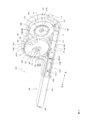
Classifications
-
- G—PHYSICS
- G02—OPTICS
- G02B—OPTICAL ELEMENTS, SYSTEMS OR APPARATUS
- G02B6/00—Light guides; Structural details of arrangements comprising light guides and other optical elements, e.g. couplings
- G02B6/24—Coupling light guides
- G02B6/36—Mechanical coupling means
- G02B6/38—Mechanical coupling means having fibre to fibre mating means
- G02B6/3807—Dismountable connectors, i.e. comprising plugs
- G02B6/3833—Details of mounting fibres in ferrules; Assembly methods; Manufacture
- G02B6/3866—Devices, tools or methods for cleaning connectors
-
- B—PERFORMING OPERATIONS; TRANSPORTING
- B08—CLEANING
- B08B—CLEANING IN GENERAL; PREVENTION OF FOULING IN GENERAL
- B08B1/00—Cleaning by methods involving the use of tools
- B08B1/30—Cleaning by methods involving the use of tools by movement of cleaning members over a surface
-
- B—PERFORMING OPERATIONS; TRANSPORTING
- B08—CLEANING
- B08B—CLEANING IN GENERAL; PREVENTION OF FOULING IN GENERAL
- B08B7/00—Cleaning by methods not provided for in a single other subclass or a single group in this subclass
- B08B7/0028—Cleaning by methods not provided for in a single other subclass or a single group in this subclass by adhesive surfaces
-
- B—PERFORMING OPERATIONS; TRANSPORTING
- B08—CLEANING
- B08B—CLEANING IN GENERAL; PREVENTION OF FOULING IN GENERAL
- B08B2240/00—Type of materials or objects being cleaned
- B08B2240/02—Optical fibers or optical fiber connectors
Definitions
- the present invention relates to an optical connector cleaning tool for cleaning an end face of a ferrule of an optical connector.
- an optical connector cleaning tool for cleaning an optical connector there is known an optical connector cleaning tool that moves a nonwoven fabric in a state where the nonwoven fabric is in contact with an end surface of a ferrule of the optical connector (for example, see Patent Documents 1 and 2). .
- the optical connector cleaning tool described above removes dust located on the end face of the ferrule of the optical connector with a cloth.
- this cleaning tool for an optical connector since the end face of the ferrule is wiped with a cloth, a member such as a ferrule of the optical connector may be charged. For this reason, there is a possibility that dust may be attracted to the end face of the ferrule of the optical connector due to charging, or an electrical defect may occur. Further, when the ferrule end face is wiped with a cloth, dust may be rubbed on the ferrule end face of the optical connector, and the ferrule end face may be damaged.
- the present invention has been made in view of the above points, and an object of the present invention is to provide a cleaning tool for an optical connector, which is unlikely to cause charging and can accurately remove dust.
- the features of the optical connector cleaning tool according to the present invention include: A main body in which a supply holding body that has a layer capable of holding a contaminant and is held so as to be capable of supplying a cleaning body for cleaning an end face of the optical connector is stored; A cleaning head in which a cleaning body supplied from the main body is positioned, the cleaning head being held at a fixed holding position with respect to the main body, The cleaning head can be displaceable from a first position to a second position different from the first position with respect to the cleaning head while maintaining a state of being engaged with the optical connector.
- a control body A supply mechanism that transmits an operation in which the control body is displaced from the first position to the second position to the cleaning body to displace the cleaning body and supply the cleaning body to the cleaning head,
- the cleaning head is separated from an end face of the optical connector, While the control body is displaced from the first position to the second position, the cleaning body is displaced by the supply mechanism,
- the cleaning head contacts the end face of the optical connector.
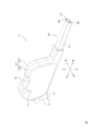
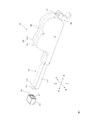
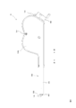
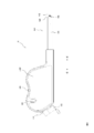
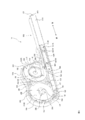
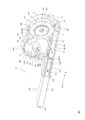
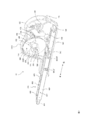
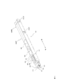
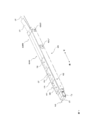
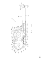
- FIG. 1 is a perspective view showing an overall outline of a cleaning tool 10 and an optical connector OC according to the present embodiment. It is a side view which shows the left side of the cleaning tool 10 by this Embodiment. It is a side view showing the right side of cleaning implement 10 by this embodiment. It is a perspective view showing the state where right housing 110R of cleaning implement 10 by this embodiment was removed. It is a perspective view showing the state where left housing 110L of cleaning implement 10 by this embodiment was removed.
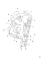
- FIG. 3 is a perspective view showing a state in which a supply reel 200 and a take-up reel 300 of the cleaning tool 10 according to the present embodiment are removed.
- FIG. 3 is a perspective view illustrating a configuration of a head unit 400 (a head unit 400 and a head holding body 420) of the cleaning tool 10 according to the present embodiment. It is a perspective view showing a course of cleaning object CT in head part 400 of cleaning implement 10 by this embodiment.
- FIG. 4 is a cross-sectional view illustrating a path of a cleaning body CT in a head unit 400 of the cleaning tool 10 according to the present embodiment. It is sectional drawing which shows the change of the movement of the winding control body 500 of the cleaning tool 10 by this Embodiment.
- a cleaning body for example, described later for cleaning an end face of an optical connector (for example, an end face ES of a ferrule FE of the optical connector described later) having a layer (for example, a resin layer RL described later) capable of holding a contaminant.
- a main body for example, a housing 100 and the like described later in which a supply holding body (for example, a supply reel 200 and the like described below) is held so as to be capable of supplying a cleaning body CT and the like.
- the cleaning head can be displaceable from a first position to a second position different from the first position with respect to the cleaning head while maintaining a state of being engaged with the optical connector.
- a control body for example, a winding control body 500 described later
- a supply mechanism for example, a rack 536 and a ratchet gear to be described later
- the optical connector cleaning tool includes a main body, a cleaning head, and a supply mechanism.
- the main body houses the supply holder for the cleaning element.
- the cleaning body is a member for cleaning the end face of the optical connector.
- the cleaning body has a layer capable of holding the contaminant (hereinafter, referred to as a holdable layer). By pressing the holdable layer against the end face of the optical connector, contaminants (such as dust) present on the end face of the optical connector can be transferred to the holdable layer, and the contaminant can be removed from the end face of the optical connector. .
- the cleaning member is held in the supply holding member so that the cleaning member can be supplied (can be sent out).
- the cleaning body preferably has a long shape. Further, the cleaning body preferably has flexibility. For example, it can be formed into a tape shape or a thread shape.
- the cleaning body may be any one that can be stored in the supply holding body so that it can be supplied.
- the size and shape of the cleaning body can be appropriately selected as long as it can supply the cleaning head from the main body and clean the end face of the optical connector.
- the cleaning head is separated from the main body and held at a fixed holding position with respect to the main body.
- the cleaning head is held at a fixed position with respect to the main body.
- the cleaning head supplied from the main body is positioned on the cleaning head.
- the control body can be engaged with the optical connector.
- the control body can be engaged with the optical connector.
- the control body can be displaced with respect to the cleaning head from a first position to a second position. The first position and the second position are separated from each other. The control body only needs to be able to be displaced relative to the cleaning head, and need not be displaced for the optical connector.
- the supply mechanism transmits the operation of the control body displacing from the first position to the second position to the cleaning body.
- the cleaning body is displaced by the transmitted operation and supplied to the cleaning head.
- the cleaning head When the control body is at the first position, the cleaning head is separated from the end face of the optical connector. That is, when the control body is at the first position, the optical connector has not yet been cleaned by the cleaning body.
- the cleaning head when the control body is located at the first position, the cleaning head is separated from the end face of the optical connector, and the cleaning head is moved from the first position to the second position.
- the cleaning head comes into contact with the end face of the optical connector when the cleaning body is located at the second position.
- the cleaning head when the control body is located at the first position, the cleaning head is separated from the end face of the optical connector, and when the control body is located at the second position, the cleaning head may be in contact with the end face of the optical connector; The cleaning head may gradually approach the end face of the connector while the control body is displaced from the first position to the second position.
- the second embodiment is the first embodiment, A head holder (for example, a head holder 420 described later) provided at a fixed position with respect to the main body and having a fixed shape, The cleaning head is provided at a fixed position of the head holder, and is held at the holding position with respect to the main body.
- a head holder for example, a head holder 420 described later
- the cleaning head is provided at a fixed position of the head holder, and is held at the holding position with respect to the main body.
- the head holder has a certain shape. That is, the shape of the head holder does not change due to the displacement of the control body or the supply mechanism, and the shape does not change over time. Further, it is preferable that the head holder has a certain size.
- the head holder is provided at a substantially constant position with respect to the main body. That is, the position of the head holder does not change due to the displacement of the control body or the supply mechanism, and the position does not change over time.
- the cleaning head is provided at a fixed position on the head holder. By doing so, the cleaning head is held at a fixed holding position with respect to the main body. Therefore, the cleaning head maintains a state where it is held at a fixed holding position with respect to the main body even when the control body is displaced and when the supply mechanism is operating.
- the cleaning head is disposed so as to protrude from the head holder and be exposed.
- the head holder may be configured separately from the main body or may be configured integrally. When configured separately, assembly and maintenance can be facilitated. When integrated, the assembling step can be omitted.
- the third embodiment is the same as the second embodiment, The head holder guides the cleaning body supplied from the main body linearly toward the cleaning head.
- the head holder also functions as a guide member for guiding the cleaning body from the main body to the cleaning head. Since the cleaning body has a layer capable of holding the contaminant, it is necessary to prevent the cleaning body from being contaminated before being guided to the cleaning head. Therefore, the head holder guides the cleaning body in a straight line (flat shape) without being curved or bent before being guided by the cleaning head. By doing so, the cleaning head can be supplied to the cleaning head in the shortest time and without contact with the head holder or other members, and contamination of the cleaning body can be prevented.
- a fourth embodiment is the third embodiment, A collection holder (e.g., a take-up reel 300 described later) that collects and holds the cleaning body supplied to the cleaning head;
- the supply mechanism transmits the operation of the control body to the collection holder, causes the collection holder to collect the cleaning body, pulls the cleaning body with the collection of the cleaning body, and moves the cleaning head from the main body. Supply the cleaning body to.
- the collection holder collects and holds the cleaning element supplied to the cleaning head. Further, the supply mechanism transmits the operation of the control body to the collection holder, causes the collection holder to collect the cleaning body, and pulls the cleaning body along with the collection operation of the cleaning body. That is, first, the supply mechanism transmits the operation of the control body to the collection holder, and the collection holder collects the cleaning body. The cleaning body is towed by the recovery operation of the cleaning body, and the towing operation is transmitted to the supply holding body via the cleaning body, and the cleaning body held by the supply holding body is supplied toward the cleaning head. Note that the cleaning body is preferably formed integrally and continuously from the supply holding body to the collection holding body via the cleaning head.
- the cleaning body is supplied from the supply holder to the cleaning head, and after the contaminant is transferred by cleaning the end face of the optical connector, the cleaning body is recovered from the cleaning head and held by the recovery holder.
- the cleaning body having the clean and holdable layer is supplied to the cleaning head, and the contaminated body is transferred by the cleaning of the end face of the optical connector, and the contaminated cleaning body is collected in the collection holding body. Therefore, a clean cleaning body can always be positioned on the cleaning head.
- the fifth embodiment is a modification of the first embodiment, Further provided is an urging force generating means (for example, a coil spring 140 and the like described below) for applying an urging force for returning the control body to a first position (for example, a maximum front position MF and the like described below) to the control body,
- the urging force generating means is arranged at a position separated from a moving path of the cleaning body.
- the urging force generating means returns the control body to the home position by applying the urging force to the control body.
- the urging force generating means is arranged at a position separated from the movement path of the cleaning body.
- the movement path of the cleaning body is a path from the supply holding body to the collection holding body via the cleaning head.
- the urging force generating means By disposing the urging force generating means at a position separated from the movement path of the cleaning body, it is possible to prevent contaminants generated by the operation of the urging force generating means from adhering to the holdable layer or the like of the cleaning body and hold the cleaning body.
- the layers can be supplied to the cleaning head while maintaining the cleanliness of the layers.
- the urging force generating means is disposed at a position separated from the head holder. Contaminants generated by the operation of the urging force generating means are less likely to reach the head holder and can be prevented from adhering to the holdable layer of the cleaning body.
- the cleaning body is preferably long and flexible, and may be in the form of a film, a nonwoven fabric, a woven fabric, or the like.
- the cleaning body may be any that can transfer and remove contaminants.
- the cleaning body is preferably formed integrally and continuously along the longitudinal direction.
- the cleaning body preferably has a coating film that covers the holdable layer in a releasable manner.
- the supply holder only needs to be housed so that the cleaning body can be sent out.
- the supply holder stores the cleaning body in the housing space and sends the cleaning body out of the housing space.
- the supply holding member is a rotating member that is rotatable around a first rotation axis (for example, a rear protruding portion 118 described later).
- the cleaning body is wound around and held by the supply holder, and is unwound according to the rotation of the supply holder, and is gradually sent out from the supply holder.
- the layer capable of holding the contaminants is covered by the adjacently overlapping cleaning elements. As the cleaning element is unwound, the adjacent cleaning elements are separated to expose a layer capable of holding the contaminant.
- the recovery holder only needs to store and recover the cleaning body.
- the collection holding body is stored in a housing space for housing the cleaning body.
- the collection holder is a rotating body that can rotate about a second rotation axis (for example, a front protrusion 116 described later) different from the first rotation axis.
- the second axis of rotation is located at a distance from the first axis of rotation.
- the second rotation axis is preferably parallel to the first rotation axis. Note that the first rotation axis and the second rotation axis may be coaxial.
- the supply holder and the recovery holder are arranged in parallel with each other.
- the supply holding body can send out the cleaning body, and the collection holding body is any as long as it can accommodate the cleaning body. Good.
- the cleaning body is gradually wound and collected according to the rotation of the supply holding body.
- the head holder has an elongated shape, and the head holder is disposed so as to protrude from the main body, and a position that protrudes from the main body and is most distant is a holding position for holding the cleaning head.
- the cleaning head can be brought closer to the optical connector through a gap between various cables such as an optical cable provided.
- the head holder has a hollow shape
- a cleaning body is movably arranged inside the head holder
- the control body can be displaced along the longitudinal direction of the head holder and outside the head holder. Since the cleaning body is disposed inside the head holding body and the control body is displaced outside the head holding body, the operation of the control body does not contaminate the cleaning body and can maintain the cleanliness of the holdable layer. it can.
- the control body preferably has a long shape.
- the head holder has two paths: a supply path in which the cleaning element sent from the supply element moves toward the cleaning head, and a collection path in which the cleaning element moves through the cleaning head toward the collection element.
- a supply path in which the cleaning element sent from the supply element moves toward the cleaning head and a collection path in which the cleaning element moves through the cleaning head toward the collection element.
- the supply path and the recovery path are located in parallel.
- that the supply path and the recovery path in the head holder are parallel means that the fluctuation width of the interval between the supply path and the recovery path in the head holder is the moving distance of the supply path and the recovery path. Means that the variation rate with respect to the moving distance is within 1/10 (1/10).
- the head holder can be made thinner, and in an environment where a large number of cables such as optical cables are arranged. Even so, the cleaning head can be brought closer to the optical connector by utilizing the gap between the cables.
- the urging force generating unit is disposed at a position separated from the movement path of the cleaning body. More specifically, the urging force generating means is arranged at a different position from the head holder. More specifically, the urging force generating means is arranged at a position separated from the supply path and the recovery path in the head holder.
- the urging force generating means is arranged at a position separated from the cleaning head with the head holder interposed therebetween.
- the urging force generating means and the cleaning head are arranged at positions separated from each other with the head holder interposed therebetween. Even when a contaminant is generated by the operation of the urging force generating means, the contaminant is less likely to reach the cleaning head, and the cleaning body supplied to the cleaning head can be kept clean.
- the urging force generating means is arranged at a position parallel to a line connecting the first rotation axis of the supply holding body and the second rotation axis of the collection holding body and adjacent to the supply holding body and the collection holding body.
- the longitudinal direction of the head holder and the control body is parallel to a line connecting the first rotation axis of the supply holder and the second rotation axis of the recovery holder.
- the head holder and the controller are coaxially arranged.
- the direction of displacement of the urging force generating means is the same as the direction of displacement of the control body.
- the urging force generated in the urging force generating means can be transmitted to the control body accurately.
- FIG. 1 is a perspective view schematically showing the entire cleaning tool 10 according to the present embodiment.
- FIG. 2 is a perspective view showing the general outline of the cleaning tool 10 according to the present embodiment and the optical connector OC.
- FIG. 3 is a side view showing the left side surface of the cleaning tool 10 according to the present embodiment.
- FIG. 4 is a side view showing the right side surface of the cleaning tool 10 according to the present embodiment.
- FIG. 5 is a perspective view showing a state where the right housing 110R of the cleaning tool 10 according to the present embodiment is removed.
- FIG. 6 is a perspective view showing a state where the left housing 110L of the cleaning tool 10 according to the present embodiment is removed.
- FIG. 7 is a perspective view showing a state where the supply reel 200 and the take-up reel 300 of the cleaning tool 10 according to the present embodiment are removed.
- FIG. 8 is a perspective view showing a configuration of right housing 110R of cleaning tool 10 according to the present embodiment.
- FIG. 9 is a perspective view showing a configuration of left housing 110L of cleaning tool 10 according to the present embodiment.
- FIG. 10 is a perspective view showing the configuration of the head 400 (the head 400 and the head holder 420) of the cleaning tool 10 according to the present embodiment.
- FIG. 11 is a perspective view showing a path of the cleaning body CT in the head unit 400 of the cleaning tool 10 according to the present embodiment. 5 to 9, the cap 160 is omitted for simplicity.
- the cleaning tool 10 is a cleaning tool (cleaning tool) for the optical connector for cleaning the end face of the ferrule of the optical connector using the cleaning body CT.
- the side and direction in which the cleaning head 410 of the cleaning tool 10 is located is referred to as a front side and a front direction
- the side and direction in which the housing 100 is located are referred to as a rear side and a rear direction
- the front-rear direction may be referred to as the longitudinal direction of the head unit 400.
- the right side or direction from the rear side to the front side is referred to as right side or right direction
- the left side or direction from the rear side to the front side is referred to as left side.
- a supply reel 200 described later is located upstream, and a take-up reel 300 is located downstream.
- the cleaning body CT is long and flexible, and has at least a resin layer.
- the resin layer can remove dirt such as dust by contacting the connector end surface and the guide pins GP.
- the cleaning body CT has, for example, an integral and continuous shape such as a tape shape or a thread shape.
- the width of the cleaning body CT is not particularly limited, but may be at least the width of the end surface ES of the ferrule FE of the optical connector to be cleaned or the width including the guide pins GP.
- the thickness of the cleaning body CT is not particularly limited, but may be, for example, 0.05 mm to 2 mm.
- the cleaning body CT may be a resin layer alone or may be laminated on a base material. Further, a release film may be laminated.
- the base material can be used as a support material when the cleaning body CT cannot be supported only by the resin layer.
- the release film can be used to protect the cleaning surface of the cleaning body CT from dirt and damage while the cleaning tool 10 of the present invention is not used.
- the cleaning body CT is sent to the cleaning body head, and is brought into contact with the end surface ES of the ferrule FE of the optical connector and the guide pins GP on the cleaning body head.
- the base material is laminated on the surface of the resin layer in contact with the cleaning body head.
- the release film is laminated on the surface of the resin layer on the side opposite to the substrate. The release film is peeled off before the cleaning body CT reaches the cleaning body head, and is removed from the cleaning body CT.
- the resin layer is not particularly limited as long as dirt can be removed by contact with the end surface ES of the ferrule FE of the optical connector and the guide pin GP.
- an adhesive, a resin foam (foam), and the guide pin GP are embedded.
- a resin, a nonwoven fabric, a woven fabric, or the like having flexibility to pierce or penetrate.
- the material of the adhesive known materials can be used, and examples thereof include a rubber-based adhesive, an acrylic-based adhesive, a silicone-based adhesive, and a urethane-based adhesive.
- These pressure-sensitive adhesives may contain additives such as tackifiers and fillers.
- Known pressure-sensitive adhesives have the advantage that they are readily available and can easily modify the adhesion and the effect of preventing adhesive residue.
- the adhesive may be an adhesive as long as it has a function of attaching dirt to the cleaning body CT by contact, and for example, an olefin-based adhesive having weak tackiness may be used. It is preferable that the adhesive is one that suppresses or prevents contamination of the connector end face such as adhesive residue when the adhesive comes into contact with the connector end face and the guide pin GP.
- a known resin foam (foam) can be used.
- the mechanism by which dirt can be captured on the cleaning surface formed by the resin foam (foam) needs to be verified for elucidation. For example, dirt pressed against the flexible cleaning surface is buried in the resin foam (foam) ( As an example, it is conceivable that the film is hardly detached from the cleaning surface due to being partially buried, and is captured by the resin foam (foam).
- the material of the resin foam (foam) is not particularly limited, and a known material can be used.
- resin foam containing urethane resin, (meth) acrylic resin, saturated polyester resin, vinyl acetate resin, vinyl chloride resin, epoxy resin, olefin resin, styrene resin, melamine resin, urea resin phenol resin, silicone resin, etc. (Foam).
- urethane foam is preferred because of its excellent flexibility and low compression set.
- a (meth) acrylic foam because it is excellent in strength, lightweight and heat insulating.
- a resin foam (foam) is used by mixing a urethane foam and a (meth) acrylic foam
- the properties of the urethane foam and the properties of the acrylic foam are adjusted according to the mixing ratio according to the application. This is preferable because it can be adjusted.
- the structure of the cells contained in the resin foam (foam) is not particularly limited, and a known structure can be used.
- a closed cell structure in which each cell exists independently in the resin foam (foam) or an open cell structure in which each cell is continuously connected in the resin foam (foam) Can have.
- the open-cell structure includes a case in which each bubble is connected by a communicating through-hole and a case in which the walls of closed cells are broken to be connected.
- a resin foam (foam) having an open-cell structure is preferable because the guide pins GP can easily pierce or penetrate the resin foam (foam) and can efficiently remove dust.
- the method for producing the resin foam (foam) is not particularly limited, and the foam can be produced by a known method.
- the resin foam (foam) may be of any of the production methods of chemical foaming and physical foaming, and may be an open cell foam in which closed cells are formed, and then the cells are physically pulverized and communicated.
- the method for producing a foam disclosed in Japanese Patent Application Laid-Open No. 2012-56985 is suitable.
- a known resin can be used as the resin having flexibility, and examples thereof include a polyurethane resin and a polyacryl resin. Further, a gel material obtained by gelling them can be included. As the gel material, a soft polyurethane resin generally called a polyurethane gel can be used. The gel material is easily deformed, and at the same time, the guide pin GP can be easily embedded, pierced, or penetrated. In this case, even when the adhesive strength of the gel material is weak, dirt can be removed from the end face of the optical connector and the guide pins GP by burying effect due to the softness of the soft polyurethane and by piercing or penetrating.
- the gel material is slightly sticky, it is easy to attach and detach the optical connector, there is no adhesive residue, etc., and the surface of the soft polyurethane with dirt attached is cleaned with a dust-free cloth wetted with water, Reusable.
- a flexible composition disclosed in JP-A-2001-316448 can be suitably used.
- the material of the base material is not particularly limited, and a known material can be used.
- synthetic resins resins such as natural resins, rubbers such as natural rubbers and synthetic rubbers, and natural fibers, synthetic fibers, fibers, and paper formed in a sheet shape can be used. Any of these materials can be used as long as the effects of the present invention are not impaired.
- an extruded resin sheet, narrow cutting of a resin sheet, twisting of fibers, knitting of fibers (such as a mesh material or a woven fabric), a laminated cloth, a nonwoven fabric, and paper can be used.
- a mesh material having a mesh structure with a mesh size of about 0.5 to 2.0 mm can be used.
- the base material is preferably an olefin-based or polyvinyl chloride-based synthetic resin.
- the guide pin GP penetrates the cleaning body CT when the cleaning body CT and the optical connector come into contact with each other, it is preferable to use a structure that allows easy penetration or a base material that is easy to penetrate.
- a braided fiber, a laminated cloth, a nonwoven fabric, or the like formed in a net shape can be suitably used.
- a part of the resin layer can be made to enter (impregnate) the voids in the substrate. .
- the adhesion between the base material and the resin layer becomes strong. Therefore, when removing the end face ES and the guide pin GP of the ferrule FE of the optical connector from the cleaning body CT, the resin layer is detached from the base material and adheres to the end face ES and the guide pin GP of the ferrule FE of the optical connector.
- adhesive residue hardly occurs.
- ⁇ Paper, non-woven fabric, woven fabric or resin film can be suitably used as the base material that is easily penetrated.
- the resin that can be easily penetrated is not particularly limited, but a resin such as a polyolefin resin such as a polyethylene resin which breaks easily after exhibiting a certain elongation, or a uniaxially or biaxially stretched polypropylene resin (PP)
- PP polypropylene resin
- a resin that has been subjected to easy-cutting processing such as polyethylene or polyethylene terephthalate resin (PET) can be suitably used.
- a known material can be used for the release film, and is not particularly limited. It is sufficient that the surface on the resin layer side of a sheet-like material such as a resin film or paper is subjected to a peeling process.
- the release processing is not particularly limited, and examples thereof include a method of applying a release agent such as dimethylsiloxane.
- the cleaning tool 10 mainly includes a housing 100, a supply reel 200, a take-up reel 300, a head unit 400, and a take-up control body 500.
- the housing 100, the supply reel 200, the take-up reel 300, the head unit 400, and the take-up control body 500 are formed of an ABS resin (acrylonitrile, butadiene, styrene copolymer synthetic resin), a POM (polyacetal) resin, or the like.
- the housing 100 rotatably holds the supply reel 200 and the take-up reel 300.
- the housing 100 stores the supply reel 200 and the take-up reel 300 along the front-rear direction.
- the take-up reel 300 is located on the front side, and the supply reel 200 is located on the rear side.
- the housing 100 has an elongated shape as a whole.
- the housing 100 has a recess 150 in a region between the supply reel 200 and the take-up reel 300, so that the operator's finger can be easily engaged and the operation of the operator can be performed accurately.
- the housing 100 has a right housing 110R and a left housing 110L.
- the housing that forms the right part of the housing 100 is the right housing, and the housing that forms the left part of the housing 100 is the left housing.
- the right housing 110R has a locking claw 154, and the left housing 110L has a locking hole 152.
- the outer shape of the right housing 110R and the outer shape of the left housing 110L are formed substantially line-symmetrically.
- the right housing 110R and the left housing 110L face each other, and the locking claws of the right housing 110R are locked in the locking holes of the left housing 110L, whereby the housing 100 can be integrally formed.
- Right housing 110R is a housing that constitutes a right side portion of the housing 100.
- ⁇ Guiding groove 112R Two guide grooves 112R are formed in the lower portion of the right housing 110R. By engaging the guide groove 112R with the guide ridge 512R formed on the right side surface of the winding control body 500, the winding control body 500 can be moved while being guided in the front-rear direction.
- the stopper 114RF is arranged at the front of the lower part of the right housing 110R, and the stopper 114RR is arranged at the rear of the lower part of the right housing 110R.
- the stopper 114RF defines a maximum front position MF of the winding control body 500, and the stopper 114RR defines a maximum rear position MR of the winding control body 500.
- the stopper 114RF and the stopper 114RR are engaged with the movement control hole 514R formed on the right side of the winding control body 500 to stop the winding control body 500 at the maximum front position MF (FIG. 13A described later). State) or the winding control body 500 can be stopped at the maximum rear position MR (the state of FIG. 14 described later).
- the stopper 114RF is engaged with a front locking hole 424RF formed on the right side surface of the head holder 420, and the stopper 114RR is formed on the rear side hole formed on the right side surface of the head holder 420.
- the head holder 420 is locked to the housing 100 by engaging with the locking hole 424RR.
- ⁇ Front protrusion 116 and rear protrusion 118 (rotatably held)>
- the front protrusion 116 and the rear protrusion 118 are formed to protrude rightward.
- the through-hole 330 of the take-up reel 300 is inserted into the front protrusion 116, and the front protrusion 116 holds the take-up reel 300 rotatably.
- the through-hole 230 of the supply reel 200 is inserted into the rear protrusion 118, and the rear protrusion 118 rotatably holds the supply reel 200.
- the remaining amount confirmation window 120 is a through hole for visually confirming the amount (remaining amount) of the remaining cleaning body CT wound around the supply reel 200. The operator can check the remaining amount of the cleaning body CT and proceed with the operation.
- the pawl holding portion 122R is formed in a concave shape (dent shape), and can accommodate and hold the fixed end portion 192 of the take-up reel pawl 190.
- the fixed end 192 of the take-up reel pawl 190 is fixed to the pawl holding portion 122R.
- the spring holding portion 124R faces the spring holding portion 124L described later, and holds the coil spring 140 so as to be able to expand and contract. In particular, even when the coil spring 140 is contracted, the coil spring 140 can be stably held by maintaining the cylindrical shape.
- the spring engagement housing portion 128 accommodates a spring engagement portion 126 formed in the left housing 110L described later. By covering the spring locking portion 126 with the spring locking housing portion 128, the fixed end 142 of the coil spring 140 locked by the spring locking portion 126 can be prevented from coming off the spring locking portion 126.
- ⁇ Left housing 110L >> ⁇ Guiding groove 112L>
- Two guide grooves 112L are formed in the lower portion of the left housing 110L.
- the guide groove 112L is engaged with the guide protrusion 512L formed on the left side surface of the winding control body 500, so that the winding control body 500 can be moved while being guided in the front-rear direction.
- the stopper 114LF is arranged at the front of the lower part of the left housing 110L, and the stopper 114LR is arranged at the rear of the lower part of the left housing 110L.
- the maximum front position MF and the maximum rear position MR of the winding control body 500 are defined.
- the stopper 114LF defines a maximum front position MF of the winding control body 500
- the stopper 114LR defines a maximum rear position MR of the winding control body 500.
- the stopper 114LF and the stopper 114LR engage with a movement control hole 514L formed on the left side of the winding control body 500 to stop the winding control body 500 at the maximum front position MF, or to wind at the maximum rear position MR.
- the control body 500 can be stopped.
- the stopper 114LF is engaged with a front locking hole 424LF formed on the left side surface of the head holder 420, and the stopper 114LR is formed on the rear side hole formed on the left side surface of the head holder 420.
- the head holder 420 is locked to the housing 100 by engaging the locking holes 424LR.
- the pawl holding portion 122L is formed in a concave shape (recessed shape), and can house and hold the fixed end portion 182 of the supply reel pawl 180.
- the fixed end 182 of the supply reel pawl 180 is fixed to the pawl holding part 122L.
- the spring holding portion 124L faces the spring holding portion 124R and holds the coil spring 140 so as to be able to expand and contract.
- the spring locking portion 126 locks the fixed end 142 of the coil spring 140.
- the spring locking portion 126 can stably hold the coil spring 140 even when the coil spring 140 expands and contracts.
- the spring engagement portion 126 is housed in the spring engagement housing portion 128 formed on the right housing 110R described above.
- the fixed end 142 of the coil spring 140 can be prevented from coming off the spring locking portion 126.
- a cleaning body guide roller 130 is rotatably provided between the supply reel 200 and the take-up reel 300.
- the cleaning body guide roller 130 has a substantially cylindrical shape.
- the cleaning body guide roller 130 contacts the cleaning body CT and curves the cleaning body CT to change the moving direction of the cleaning body CT.
- the cleaning body CT sent from the supply reel 200 can be changed in a certain direction and guided toward the cleaning head 410.
- the cleaning body CT can be stably sent out toward the cleaning head 410 without depending on the remaining amount of the cleaning body CT wound on the supply reel 200. .
- the coil spring 140 is a spring formed in a coil shape, and is formed to be extendable and contractible. In each of the figures, the coil spring 140 is shown in a cylindrical shape for simplicity. The coil spring 140 generates an urging force according to the state of expansion and contraction.
- the coil spring 140 has two ends, a fixed end 142 and a moving end 144. The fixed end 142 is locked by the spring locking portion 126 of the left housing 110L. The moving end 144 is engaged with the coil spring pressing portion 540 of the winding control body 500. When the winding control body 500 moves to the rear side, the coil spring 140 contracts, and when the winding control body 500 moves to the front side, the coil spring 140 expands. The coil spring 140 applies an urging force to the winding control body 500.
- the supply reel pawl 180 has a leaf spring structure, and has a fixed end 182 and a leaf spring 184.
- the fixed end 182 is fixed to the pawl holding part 122L of the left housing 110L.
- the leaf spring portion 184 has a long shape, and can be elastically deformed by bending in a direction perpendicular to the longitudinal direction.
- the distal end of the leaf spring portion 184 has an engagement end 186.
- the engagement end 186 has a bent shape.
- the engagement end 186 engages with the ratchet gear 222 of the pinion body 220 of the supply reel 200.
- the leaf spring portion 184 functions as a ratchet claw. The ratchet mechanism by the leaf spring 184 will be described later.
- the take-up reel pawl 190 has a leaf spring structure, and has a fixed end 192 and a leaf spring 194.
- the fixed end 192 is fixed to the pawl holding portion 122R of the right housing 110R.
- the leaf spring portion 194 has a long shape, and can be elastically deformed by bending in a direction perpendicular to the longitudinal direction.
- a leaf spring portion 194 has an engagement end 196 at a tip thereof.
- the engagement end 196 has a bent shape.
- the engagement end 196 is engaged with the ratchet gear 322 of the pinion body 320 of the take-up reel 300.
- the leaf spring portion 194 functions as a ratchet claw. The ratchet mechanism by the leaf spring portion 194 will be described later.
- the cap 160 is a cover for detachably covering the cleaning head 410. By covering the cleaning head 410 with the cap 160, contamination of the resin layer RL of the cleaning body CT can be prevented. Further, a cap holding portion 170 is formed at a rear portion of the housing 100. When performing a cleaning operation with the cleaning tool 10, it is necessary to remove the cap 160 from the cleaning head 410. By attaching the removed cap 160 to the cap holding portion 170, the operator can clean the cap 160 without holding the cap 160 by hand, thereby simplifying the cleaning operation.
- the supply reel 200 mainly has a left supply reel frame 210L and a right supply reel frame 210R. An unused cleaning body CT is wound between the left supply reel frame 210L and the right supply reel frame 210R so that it can be sent out (suppliable).
- the left supply reel frame 210L has a substantially disk shape.
- the left supply reel frame 210L mainly has a pinion body 220, a fixing portion 224, and a through hole 230.
- the left supply reel frame 210L has a pinion body 220.
- the pinion body 220 is formed outside the left supply reel frame 210L (on the side facing the left housing 110L).
- the pinion body 220 has a substantially cylindrical shape with a low height.
- the pinion body 220 is formed coaxially with the left supply reel frame 210L.
- a ratchet gear (ratchet gear) 222 is formed along the outer peripheral surface of the pinion body 220.
- the ratchet gear 222 is constituted by a row of teeth having an asymmetric tooth surface.
- the teeth of the ratchet gear 222 have a tooth surface with a small pressure angle (a tooth surface with a steep inclination (a large inclination)) (hereinafter referred to as a large inclined tooth surface) and a tooth surface with a large pressure angle (an inclined surface). (Hereinafter referred to as a small inclined tooth surface).
- the engagement surface is constituted by the large inclined tooth surface, and the slip surface and the sliding surface are constituted by the small inclined tooth surface.
- the rotation direction in which the rotation of the supply reel 200 is permitted (rotation permission direction) and the rotation direction in which the rotation of the supply reel 200 is prohibited (rotation prohibition direction) can be defined by the inclination of the tooth surface.
- the ratchet gear 222 and the engagement end 186 of the supply reel pawl 180 constitute a ratchet mechanism (return preventing mechanism).
- the supply reel 200 permits rotation in a first rotation direction (for example, clockwise) (rotation permission direction), while a second rotation direction (for example, a rotation direction opposite to the first rotation direction). , Counterclockwise) can be prohibited (rotation prohibited direction).
- a first rotation direction for example, clockwise
- a second rotation direction for example, a rotation direction opposite to the first rotation direction
- Counterclockwise can be prohibited (rotation prohibited direction).
- the fixing portion 224 is formed to protrude from the center of the left supply reel frame 210L. In the supply reel 200, the fixed portion 224 is disposed toward the right supply reel frame 210R.
- the fixing portion 224 has a gap (not shown (similar to a gap 326 of the fixing portion 324 of the take-up reel 300 described later)), and a first end (not shown) on the longitudinal side of the cleaning body CT. The cleaning body CT is fixed by being held in the gap.
- a flat portion 228 is formed at the tip of the fixing portion 224, and can hold the right supply reel frame 210R.
- a through hole 230 is formed in the center of the left supply reel frame 210L, and the rear protrusion 118 of the right housing 110R is inserted into the through hole 230.
- the right supply reel frame 210R has a substantially disk shape.
- a circular through-hole 232 is formed at the center of the right supply reel frame 210R, and the fixing portion 224 of the left supply reel frame 210L is inserted into the through-hole 232.
- the cleaning body CT is wound around a gap between the left supply reel frame 210L and the right supply reel frame 210R. By rotating the supply reel 200, the unused cleaning body CT wound on the supply reel 200 can be gradually sent out and sent out toward the cleaning head 410.
- the adhesive resin layer is covered by the cleaning body CT that is adjacently overlapped.
- the cleaning body CT that has been adjacently overlapped is separated and the adhesive resin layer is exposed.
- Take-up reel 300 >>>>
- the take-up reel 300 has a right take-up reel frame 310R.
- the used cleaning body CT is wound around the take-up reel 300.
- Right take-up reel frame 310R has a substantially disk shape.
- the right take-up reel frame 310 ⁇ / b> R mainly has a pinion body 320, a fixing portion 324, and a through hole 330.
- the right take-up reel frame 310R has a pinion body 320.
- the pinion body 320 is formed outside the right take-up reel frame 310R (on the side facing the right housing 110R).
- the pinion body 320 has a substantially cylindrical shape with a low height.
- the pinion body 320 is formed coaxially integrally with the right take-up reel frame 310R.
- a ratchet gear (ratchet gear) 322 is formed along the outer peripheral surface of the pinion body 320.
- the ratchet gear 322 is constituted by a row of teeth having an asymmetric tooth surface.
- the teeth of the ratchet gear 322 are constituted by a tooth surface with a small pressure angle (a steep tooth surface) and a tooth surface with a large pressure angle (a steep tooth surface) across the tooth tip.
- the rotation direction in which rotation of the take-up reel 300 is permitted (rotation permission direction) and the rotation direction in which rotation is prohibited (rotation prohibition direction) can be defined by the inclination of the tooth surface.
- the ratchet gear 322 and the engaging end 196 of the take-up reel pawl 190 constitute a ratchet mechanism (return preventing mechanism).
- the take-up reel 300 allows rotation in a first rotation direction (for example, clockwise) (rotation permission direction), while rotating in a second rotation direction (direction opposite to the first rotation direction). For example, it is possible to prohibit (counterclockwise) rotation (rotation prohibition direction).
- the fixing portion 324 is formed to protrude from the center of the right take-up reel frame 310R. In the take-up reel 300, the fixing portion 324 is arranged toward the left housing 110L. The fixing portion 324 has a gap 326, and the cleaning body CT is fixed by sandwiching a second end (not shown) on the long side of the cleaning body CT in the gap 326. A through-hole 330 is formed in the center of the right take-up reel frame 310R, and the front protrusion 116 of the right housing 110R is inserted into the through-hole 330.
- the left take-up reel frame does not exist, but a left take-up reel frame may be provided.
- a left take-up reel frame may be provided.
- the head section 400 is disposed so as to protrude forward from the housing 100.
- the head section 400 has a cleaning head 410 and a head holder 420.
- the cleaning head 410 has a contact portion 412 for bringing the cleaning body CT into contact with the end surface ES of the ferrule FE of the optical connector.
- the contact portion 412 has a size and a shape corresponding to the end surface ES of the ferrule FE of the optical connector.
- the contact portion 412 is formed with two receiving holes 414 for receiving two guide pins GP protruding from the end surface ES of the ferrule FE of the optical connector.
- the resin layer RL of the cleaning body CT can reach the root of the guide pin GP on the end surface ES of the ferrule FE of the optical connector, and dust near the root of the guide pin GP can be accurately removed. Can be removed. The removal of dust adhering to the vicinity of the root of the guide pin GP will be described later in detail (see FIGS. 16 and 17 described later).
- the cleaning head 410 has a long, thin and flat rectangular parallelepiped shape.
- the cleaning head 410 is held at a predetermined position on a front end 426 of a head holder 420 described later.
- the cleaning body CT sent out from the supply reel is guided by the contact portion 412 and positioned at the contact portion 412.
- the cleaning head 410 can be provided detachably on the head holder 420. Depending on the end surface ES of the ferrule FE of the optical connector, the corresponding cleaning head 410 can be appropriately replaced.
- the resin layer RL of the cleaning body CT positioned at the contact portion 412 is opposed to the end face ES of the ferrule FE of the optical connector, and the resin layer RL is brought into contact with the end face ES of the ferrule FE of the optical connector.
- dust existing on the end surface ES of the ferrule FE of the optical connector is transferred to the resin layer RL.
- dust on the end surface ES of the ferrule FE of the optical connector can be removed.
- the cleaning body CT is wound up from the contact portion 412 toward the take-up reel 300. The displacement of the cleaning body CT will be described later in detail.
- the head holder 420 has a long and constant shape. Specifically, the head holder 420 has a long rectangular tube shape, and has a hollow structure.
- the head holding body 420 movably accommodates the cleaning body CT from the supply reel 200 to the take-up reel 300. Specifically, the head holding body 420 can move the cleaning body CT until it is sent out from the supply reel 200 and is taken up by the take-up reel 300 via the contact section 412 of the cleaning head 410 described above. To accommodate.
- a holding hole 422 is formed on the side surface of the front part of the head holder 420.
- a pin 416 formed on the cleaning head 410 is inserted into the holding hole 422. In this manner, the cleaning head 410 can be held at a fixed position on the head holder 420.
- Two locking holes 424RF and 424RR are formed on the right side surface of the rear part of the head holder 420.
- the locking hole 424RF is formed on the front side
- the locking hole 424RR is formed on the rear side.
- the front locking hole 424RF engages with the stopper 114RF of the right housing 110R
- the rear locking hole 424RR engages with the stopper 114RR of the right housing 110R.
- two locking holes 424LF and 424LR are formed on the left side surface of the rear part of the head holder 420.
- the locking hole 424LF is formed on the front side
- the locking hole 424LR is formed on the rear side.
- the front locking hole 424LF engages with the stopper 114LF of the left housing 110L
- the rear locking hole 424LR engages with the stopper 114LR of the left housing 110L.
- the head portion 400 can be held at a fixed position of the housing 100.
- the cleaning head 410 has a fixed shape and is held at a fixed position of a head holder 420 locked at a fixed position with respect to the housing 100. Therefore, the cleaning head 410 is always located at a fixed position with respect to the housing 100. That is, the cleaning head 410 does not move relative to the housing 100 before, during, and after the cleaning operation, and is always at a fixed position with respect to the housing 100 and the head holder 420. Will be retained. Since the cleaning head 410 is held at a fixed position with respect to the housing 100 and the head holding body 420, the cleaning body CT supplied to the abutting portion 412 of the cleaning head 410 can be used for the ferrule FE of the optical connector. The end surface ES can be pressed with a constant force, and the dust on the end surface ES can be stably removed without depending on the skill of the operator.
- the front end of the cleaning head 410 protrudes from the head holder 420, and the contact portion 412 of the cleaning head 410 is disposed at a position protruding from the head holder 420.
- the cleaning body CT is exposed to the outside, and the cleaning body CT supplied to the abutting portion 412 can be accurately brought into contact with the end surface ES of the ferrule FE of the optical connector.
- the resin layer RL of the cleaning body CT can be less likely to be contaminated.
- the cap 160 described above can be attached to the cleaning head 410, and when the cleaning tool 10 is not used, the resin layer RL of the cleaning body CT can be prevented from being contaminated, and a clean state can be maintained.
- a movable control body 510 described later is arranged outside the head holder 420, and the head holder 420 functions as a partition. For example, even when dust is generated due to sliding (movement) of the control main body 510, the dust can be blocked by the head holder 420 and made difficult to enter the inside of the head holder 420, and contamination of the resin layer RL can be reduced. Can be prevented.
- the coil spring 140 for driving the control body 510 is disposed at the rear of the housing 100, that is, at a position separated from the head holder 420, and dust is generated by expansion and contraction of the coil spring 140. Even in this case, contamination of the resin layer RL can be prevented.
- the coil spring 140 disposed at the rear of the housing 100 is housed inside the spring holding portions 124L and 124R, and the spring holding portions 124L and 124R function as partition walls, and dust due to expansion and contraction of the coil spring 140 spreads. Can be prevented.
- the head holder 420 has three openings 428 along the moving direction of the cleaning body CT.
- the head holder 420 has a so-called lightened shape.
- the take-up control body 500 has a control main body 510, a control end face 520, a take-up extending part 530, and a coil spring pressing part 540.
- the control main body 510 has a long and substantially rectangular tube shape, and penetrates in the longitudinal direction. That is, the control main body 510 has a hollow structure, and the above-described head unit 400 (the head holder 420 and the cleaning head 410) is housed inside the control main body 510.
- the control main body 510 can move along the longitudinal direction of the head unit 400 with respect to the head unit 400 housed inside.
- the control body 510 can move outside the head section 400 along the longitudinal direction of the head section 400, and the movement of the control body 510 causes the entire winding control body 500 to move relative to the head section 400 and the housing 100. Accordingly, the head 400 can move along the longitudinal direction.
- the operation and operation of the winding control body 500 will be described later.
- Two guide ridges 512R are formed on the right side surface of the control main body 510.
- the two guide projections 512R have a long ridge shape.
- the two guide ridges 512R are formed in two places along the longitudinal direction of the control main body 510, parallel to each other, at the upper part and the lower part of the right side surface of the control main body 510.
- Two guide ridges 512L are formed on the left side surface of the control body 510.
- the two guide projections 512L have a long ridge-like shape.
- the two guide ridges 512R are formed in parallel with each other along the longitudinal direction of the control main body 510, at two locations: an upper portion and a lower portion on the left side surface of the control main body 510.
- a long movement control hole 514R is formed on the right side surface of the control main body 510.
- the movement control hole 514R has a substantially elliptical through-hole shape.
- the movement control hole 514R is formed between two elongated guide ridges 512R along the longitudinal direction of the control main body 510.
- a long movement control hole 514L is formed on the left side surface of the control body 510.
- the movement control hole 514L has a shape of a substantially elliptical through-hole.
- the movement control hole 514L is formed between two elongated guide projections 512L along the longitudinal direction of the control main body 510.
- the movement control hole 514R and the movement control hole 514L are formed on the right side surface and the left side surface of the control main body 510 so as to face each other.
- Control end surface 520 is an end face formed at the front end of the control main body 510.
- the control end surface 520 faces the housing end surface OS of the optical connector OC, abuts against the housing end surface OS, and is formed to be able to engage with the housing end surface OS.
- the control end surface 520 is turned on by the light.
- the cleaning tool 10 is positioned so as to face the housing end face OS of the connector OC, and is brought close to the control end face 520 until it comes into contact (engagement) with the housing end face OS of the optical connector OC.
- the control main body 510 when the operator applies a force to the cleaning tool 10 while maintaining the state in which the control end surface 520 of the control main body 510 is in contact with (engagement with) the housing end surface OS of the optical connector OC, the control main body 510 becomes: While being pressed by the housing end face OS, it relatively moves to the rear of the housing 100, and the contact part 412 of the cleaning head 410 approaches the end face ES of the ferrule FE of the optical connector OC.
- the cleaning body CT is newly sent out from the supply reel 200, and the cleaning body CT supplied to the contact portion 412 of the cleaning head 410 moves. .
- the control main body 510 moves relatively further to the rear of the housing 100, and the abutting portion 412 of the cleaning head 410 is moved to the end face of the ferrule FE of the optical connector OC. It comes closer to the ES and makes contact.
- the control body 510 further moves to the rear of the housing 100, the cleaning body CT is newly sent out from the supply reel 200, and the clean resin layer RL of the cleaning body CT is supplied to the contact portion 412 of the cleaning head 410. Is done.
- the operator applies a force to the cleaning tool 10 to push the cleaning tool 10 into the optical connector OC, thereby cleaning the contact portion 412 of the cleaning head 410 while approaching the end surface ES of the ferrule FE of the optical connector OC.
- the body CT is sent out from the supply reel 200, and the clean resin layer RL of the cleaning body CT can always be brought into contact with the end surface ES of the ferrule FE.
- the specific operations of the cleaning head 410, the control body 510, and the cleaning body CT will be described later with reference to FIGS.
- the control main body 510 moves relatively to the housing 100 and the head part 400, but the contact part 412 of the cleaning head 410 is moved to the ferrule of the optical connector OC.
- the state is engaged with the end surface ES of the FE, and the winding control body 500 and the control main body 510 are in a state of being stationary with respect to the optical connector OC.
- the housing 100 and the head unit 400 move toward the optical connector OC.
- the winding extension 530 extends from the control body 510 toward the winding reel 300.
- the winding extending portion 530 has a curved portion 532 and a rack forming portion 534.
- the curved portion 532 has a shape curved approximately 90 degrees.
- the curved portion 532 protrudes substantially perpendicularly to the longitudinal direction of the head portion 400, curves approximately 90 degrees, and extends substantially parallel to the longitudinal direction of the head portion 400 toward the take-up reel 300.
- the curved portion 532 is formed of a material that can be elastically deformed, and can be appropriately elastically deformed.
- the rack forming portion 534 is connected to the curved portion 532 and has a substantially linear and long shape.
- the rack forming section 534 has a rack (a row of teeth whose teeth are arranged in a plane) 536 formed along the longitudinal direction of the head section 400.
- the rack 536 engages with the ratchet gear 322 of the take-up reel 300.
- the rack forming section 534 can also move in the front-rear direction.
- the take-up reel 300 can be rotated by moving the rack forming section 534 in the front-rear direction. Operations of the control main body 510 and the take-up reel 300 will be described later in detail.
- a coil spring pressing portion 540 is formed at the rear end of the winding control body 500.
- the moving end 144 of the coil spring 140 is engaged with the coil spring pressing portion 540.
- the side portion of the coil spring 140 is supported by the spring holding portion 124L and the spring holding portion 124R, and the coil spring 140 is stretchably held between the coil spring pressing portion 540 and the spring engaging portion 126 of the left housing 110L.
- control main body 510 has a hollow structure, and is housed inside the control main body 510 in the above-described head unit 400 (the head holder 420 and the cleaning head 410).
- the control main body 510 can move outside the head unit 400 with respect to the head unit 400 housed inside. Specifically, when the operator pushes the cleaning tool 10 into the optical connector OC, the control main body 510 is engaged with the housing end surface OS of the optical connector OC, and the control body 510 is moved in the longitudinal direction of the head section 400 (that is, the cleaning body CT). The control body 510 can be moved along the front-back direction).
- FIG. 13A shows a state when the control main body 510 is located at the forefront side.
- the control main body 510 is locked by the stopper 114RF and the stopper 114LF, and the control main body 510 is located at the foremost side.
- the maximum front position MF is the home position of the control main body 510.
- FIG. 13B shows a state where the control main body 510 has moved slightly backward from the maximum forward position MF.
- the control main body 510 is controlled. 510 is pressed by the housing end face OS and moves from the maximum front position MF toward the rear of the housing 100.
- control main body 510 moves to the rear side, a part of the control main body 510 is housed inside the housing 100, and a part of the head holding body 420 is exposed from the control main body 510, and the contact of the cleaning head 410 is prevented.
- the contact portion 412 approaches the end surface ES of the ferrule FE of the optical connector OC.
- FIG. 14 shows that when the movement control hole 514R is engaged with the stopper 114RR and the movement control hole 514L is engaged with the stopper 114LR, the control body 510 is locked by the stopper 114RR and the stopper 114LR, and It is located on the rear side (maximum rear position MR). Thus, the control main body 510 can be stopped at the maximum rear position MR. By stopping the control body 510 at the maximum rear position MR, even when the operator tries to strongly press the ferrule FE of the optical connector OC by increasing the force for pushing the cleaning tool 10 into the optical connector OC, the ferrule FE is not used. Can be prevented from being damaged.
- the coil spring 140 is provided at the rear of the control main body 510, and the coil spring 140 applies an urging force to the control main body 510.
- the control main body 510 can move to the maximum front position MF and return to the home position by the urging force of the coil spring 140.
- the winding control body 500 can move between the maximum front position MF and the maximum rear position MR.
- the control main body 510 has the extending portion 530 for winding, and the extending portion 530 for winding has the rack 536 formed thereon.
- the rack 536 is engaged with the ratchet gear 322 of the take-up reel 300.
- the take-up reel pawl 190 has a leaf spring portion 194, and the leaf spring portion 194 has an engaging end 196 formed therein.
- This engagement end 196 also engages with the ratchet gear 322 of the take-up reel 300. That is, the ratchet gear 322 of the take-up reel 300 is engaged with two members, the rack 536 of the control body 510 and the engaging end 196 of the take-up reel pawl 190.
- the operation of the take-up reel 300 can be controlled. FIG.
- FIG. 15 is a schematic diagram showing a state of engagement between the rack 536 and the ratchet gear 322 and an engagement between the engagement end 196 and the ratchet gear 322.
- the rack 536 is covered by the winding extending portion 530 (see FIGS. 13 and 14), the rack 536 is illustrated in FIG. 15 for the sake of explanation.
- a rack-and-pinion mechanism is configured by the rack 536 of the winding extension 530 and the ratchet gear 322 of the winding reel 300, and converts a linear motion into a rotary motion to transmit the motion.
- the winding control body 500 moves forward, the inclined small tooth surface of the rack 536 of the winding extension 530 comes into contact with the inclined small tooth surface of the ratchet gear 322 of the winding reel 300. Further, as the take-up control body 500 moves, the take-up extension 530 slides on the teeth of the ratchet gear 322 and is pressed by the teeth of the ratchet gear 322 to be gradually elastically deformed. When the rack 536 of the winding extension 530 passes through the tooth tip of the ratchet gear 322, the elastic deformation is released and returns to the original shape.
- the supply reel pawl 180 has the leaf spring portion 184, and the engagement end 186 is formed in the leaf spring portion 184 (see FIG. 6).
- a ratchet gear 222 is provided on the supply reel 200.
- the engagement end 186 of the leaf spring portion 184 engages with the ratchet gear 222 of the supply reel 200.
- the engagement between the ratchet gear 222 and the engagement end 186 constitutes a reverse prevention mechanism.
- the take-up control body 500 moves forward by the urging force of the coil spring 140 without rotating the take-up reel 300 (FIG. 15 and FIG. 13 (b) arrow B1). Therefore, the winding control body 500 can be returned to the home position while maintaining the wound state without releasing the cleaning body CT wound on the winding reel 300 (FIG. 13A). State).
- the cleaning body CT contaminated with dust can be prevented from returning to the cleaning head 410.
- the take-up control body 500 is positioned at the maximum front position MF by the stoppers 114RF and 114LF, and is positioned at the maximum rear position MR by the stoppers 114RR and 114LR. For this reason, the take-up control body 500 can always be moved by a certain length (refer to FL in FIGS. 13A and 14), and the feed length of the cleaning body CT can be made constant.
- a clean resin layer RL can always be supplied to the contact portion 412 of the cleaning head 410 without depending on the skill or skill of the person.
- ⁇ path of cleaning body CT >>>
- the cleaning body CT is wound, and the resin layer RL of the cleaning body CT is covered by the adjacent cleaning body CT. Therefore, the resin layer RL of the cleaning body CT is not contaminated.
- the supply reel 200 is held by the housing 100, and the cleaning body CT sent out from the supply reel 200 is accommodated in the housing 100 and the head holding body 420 until reaching the cleaning head 410, and the resin layer RL of the cleaning body CT Can be kept clean.
- the cleaning body CT When the cleaning body CT is sent from the supply reel 200, the winding is released and the resin layer RL of the cleaning body CT is exposed. After being sent out from the reel 200, it is preferable that the resin layer RL of the cleaning body CT goes straight and reaches the cleaning head 410 without contacting any member. On the surface on the opposite side of the resin layer RL, the path of the cleaning body CT can be appropriately changed by a roller, a guide, or the like. Further, even when the resin layer RL of the cleaning body CT comes into contact with the member, the resin layer RL of the cleaning body CT can be kept clean by using a clean member.
- the take-up reel 300 rotates in the winding direction at a rotation angle corresponding to the movement of the control main body 510. (Arrow A2 in FIG. 13B).
- the cleaning body CT is pulled by the rotation of the take-up reel 300 (arrow A3 in FIG. 13B) and wound around the take-up reel 300.
- the operator increases the force on the cleaning tool 10 to bring the contact portion 412 of the cleaning head 410 closer to the end face ES of the ferrule FE of the optical connector, and moves the resin layer RL of the cleaning body CT to the ferrule of the optical connector.
- the resin layer RL of the cleaning body CT By pressing against the end surface ES of the FE, dust on the end surface ES of the ferrule FE of the optical connector is transferred to the resin layer RL, and the end surface ES of the ferrule FE of the optical connector can be cleaned.
- the cleaning body CT is continuously pulled by the relative movement of the control main body 510. That is, until the contact portion 412 of the cleaning head 410 reaches the end surface ES of the ferrule FE of the optical connector OC, the control body 510 continues to move and the cleaning body CT is pulled. Therefore, before the resin layer RL of the cleaning body CT is pressed against the end surface ES of the ferrule FE of the optical connector, the cleaning body CT located at the contact portion 412 of the cleaning head 410 is removed from the contact portion 412. It moves to the separated position, and the clean resin layer RL of the cleaning body CT is newly supplied to the contact part 412 and positioned. That is, a clean resin layer RL of the cleaning body CT can be newly supplied to the contact portion 412 before the resin layer RL of the cleaning body CT comes into contact with the end surface ES of the ferrule FE of the optical connector.
- the operator weakens the force on the cleaning tool 10 and relatively moves the control main body 510 forward by the urging force of the coil spring 140 to return to the home position.
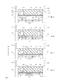
- FIGS. 16A to 16D are cross-sectional views showing a process of cleaning the end surface ES of the ferrule FE of the optical connector by using the cleaning tool 10. For example, it can be used for cleaning MPO connectors and the like.
- FIGS. 16A to 16D show a relative positional relationship between the ferrule FE and the cleaning body CT in the cleaning process.
- the ends of twelve optical fibers OF are provided side by side on the ferrule FE.
- two guide pins GP are provided to protrude vertically (in a direction away from the end surface ES) from the end surface ES of the ferrule FE with the twelve optical fibers OF interposed therebetween.
- the operator grips the cleaning tool 10 and brings the cleaning head 410 of the cleaning tool 10 into close proximity to the opening OP of the optical connector OC as shown in FIG.
- a force is applied to the cleaning tool 10 by engaging the control end face 520 of the control main body 510 with the housing end face OS of the optical connector OC.
- the cleaning head 410 can be inserted into the opening OP of the optical connector OC while the control main body 510 is housed in the housing 100, and the contact portion 412 of the head section 400 is connected to the ferrule of the optical connector OC. It can be close to the end surface ES of the FE.
- the resin layer RL of the cleaning body CT can be brought into close contact with the end face ES of the ferrule FE. The specific process will be described below.
- the resin layer RL of the cleaning body CT faces at a position separated from the end surface ES of the ferrule FE. .
- the control end face 520 of the control body 510 engages with the housing end face OS of the optical connector OC.
- the resin layer RL of the cleaning body CT of the contact part 412 of the head part 400 approaches the end face ES of the ferrule FE of the optical connector OC.
- the resin layer RL of the cleaning body CT comes into contact with the tip portions of the two guide pins GP of the ferrule FE, and is elastically deformed by being pressed by the two guide pins GP.
- the resin layer RL of the cleaning body CT further approaches the end surface ES of the ferrule FE of the optical connector OC.
- the resin layer RL is pressed by the two guide pins GP and starts to cover the two guide pins GP by the urging force (restoring force) generated on the resin layer RL.
- the resin layer RL reaches the end face ES of the ferrule FE, as shown in FIG.
- the portion elastically deformed by the contact of the two guide pins GP is covered with the resin layer RL to the root of the two guide pins GP by the urging force (restoring force) generated on the resin layer RL.
- the resin layer RL can be brought into close contact with the entire end face ES of the ferrule FE without forming a gap between the resin layer RL and the end face ES of the ferrule FE. Can be.
- the entire dust on the end face ES of the ferrule FE can be transferred by the adhesive force of the resin layer RL. Adhered to the surface by electrostatic force. Dust adhering around the roots of the two guide pins GP and on the two guide pins GP can also be removed by being transferred by the adhesive force of the resin layer RL.
- the elastic modulus and hardness of the resin layer RL By appropriately selecting the elastic modulus and hardness of the resin layer RL, the entire two guide pins GP can be covered with the resin layer RL using the urging force (restoring force) of the resin layer RL.
- the cleaning head 410 has an accommodation hole 414 for accommodating two guide pins GP.
- the resin layer RL reaches the end surface ES of the ferrule FE, the resin layer RL is formed together with the entire guide pin GP. Is accommodated in the accommodation hole 414.
- dust can be accurately removed even in the ferrule FE in which the guide pin GP is formed.
- the resin layer RL can also be accommodated in the accommodation hole 414, the deformation of the resin layer RL due to the urging force (restoring force) is not hindered, and the entire guide pin GP can be covered with the resin layer RL.
- FIGS. 16 (a) to 16 (d) show that the resin layer RL is elastically deformed according to the shape and size of the two guide pins GP without being punctured by the two guide pins GP.
- the resin layer RL may be plastically deformed.
- FIGS. 17A to 17D are diagrams illustrating an example in which the resin layer RL is plastically deformed. Whether the resin layer RL is elastically deformed or plastically deformed may be determined as appropriate, such as the Shore A hardness of the resin layer RL.
- FIG. 17A shows the same state as FIG. 16A.
- the resin layer RL is punctured by the two guide pins GP and becomes plastic. It is deformed and piercing starts from the beginning of contact with the two guide pins GP.
- FIG. 17C plastic deformation further progresses, and the two guide pins GP are gradually pierced by the resin layer RL.
- FIG. 17D the cleaning body CT reaches the end face ES of the ferrule FE while the resin layer RL is plastically deformed.
- the resin layer RL of the cleaning body CT can be attached to the roots of the two guide pins GP. Also in this case, dust adhering around the roots of the two guide pins GP and the two guide pins GP can be removed by being transferred by the adhesive force of the resin layer RL.
- the cleaning member CT may be provided with a release film.
- the release film is a film for covering the resin layer RL, and by providing the release film, the adhesiveness of the resin layer RL can be maintained or contamination can be prevented.
- the cleaning body CT When a release film is provided on the cleaning body CT, the cleaning body CT is wound around the supply reel 200 together with the release film, and when the cleaning body CT is sent from the supply reel 200, the release film can be peeled off and supplied to the cleaning head 410. .
- the peeling of the release film can be facilitated by reducing the radius of curvature and bending the cleaning body CT to increase the degree of bending of the cleaning body CT. Further, it is preferable to provide a release film storage reel for storing the release film that has been released. It is possible to prevent the peeled release film from coming into contact with the resin layer RL again and hindering the smooth movement of the cleaning body CT. Further, it is possible to prevent the adhesiveness of the resin layer RL from being lowered or the cleanliness from being lowered by the contact of the peeled release film.
- a discharge hole may be provided so that the film is discharged from the housing 100 together with the release. It is not necessary to secure a space for providing a peeling film accommodation reel, and by making the housing 100 smaller, the entire cleaning tool 10 can be reduced in size. Further, a cutter for cutting the discharged release film may be provided in the discharge hole.
- the accommodation hole 414 for accommodating the two guide pins GP is provided, but the accommodation hole 414 may not be provided.
- the contact portion 412 can be formed in a flat shape without the accommodation hole 414, and in the case of the ferrule FE having no guide pin GP, the resin layer RL is pressed with a uniform pressing force on the entire end surface ES of the ferrule FE. can do.
- FIG. 18 is a perspective view showing a state where the supply reel 200 and the take-up reel 3000 of the cleaning tool 100 are removed.
- the cleaning tool 100 shown in FIG. 18 has the same configuration except that the take-up reel 3000 is different from the take-up reel 300 of the cleaning tool 10.
- the take-up reel 300 of the cleaning tool 10 has only the right take-up reel frame 310R.
- the take-up reel 3000 has a right take-up reel frame 310R and a left take-up reel frame 310L.
- the cleaning body CT can be held between the right take-up reel frame 310R and the left take-up reel frame 310L. Therefore, when the cleaning body CT having a long shape is wound, the cleaning body CT can be prevented from meandering, and the cleaning body CT can be accurately wound on the winding reel 3000. It is possible to prevent the cleaning bodies CT from being entangled by the take-up reel 3000 beforehand, so that the cleaning bodies CT can be wound up to the end, and waste can be prevented.
- the supply reel 200 includes the right supply reel frame 210R and the left supply reel frame 210L in both the cleaning tool 10 and the cleaning tool 100. For this reason, the cleaning body CT can be supplied to the cleaning head 410 in a stable posture, contact with other members or the like can be prevented, and the cleaning body CT can be supplied to the cleaning head 410 in a clean state.
- the resin layer forming the cleaning body CT is a polyurethane resin
- the Asker C hardness of the resin layer of the cleaning body CT is preferably 40 to 90, and more preferably 65 to 85.
- the Asker C hardness of the resin layer of the cleaning body CT is within the above range, the shape of the surface to be cleaned can be followed, and the performance of collecting contaminants increases.
- the shape of the guide pin can be followed, and the cleaning effect of the guide pin and the connection end face of the optical connector can be significantly improved.
- the Asker C hardness of the resin layer of the cleaning body CT is measured by the method described in JIS K7312: 1996 “Physical test method of thermosetting polyurethane elastomer molded article”. The measurement is performed using an Asker rubber hardness tester type C. In the measurement, the resin layer of the cleaning body CT stored for 24 hours in an environment of 25 ° C. and 50% RH after the curing of the polyurethane resin is completed is used.
- the tensile strength of the resin layer of the cleaning body CT is preferably 0.55 to 30 MPa, more preferably 0.6 to 30 MPa, and particularly preferably 0.65 to 22 MPa.
- the elongation at break of the resin layer of the cleaning body CT is preferably 100 to 150 mm, more preferably 105 to 140 mm.
- the shape of the surface to be cleaned can be followed, and the performance of collecting contaminants increases.
- the shape of the guide pin can be followed, and the cleaning effect of the guide pin and the connection end face of the optical connector can be significantly improved.
- the elongation at break of the resin layer of the cleaning body CT is preferably 200 to 700%, and more preferably 400 to 650%.
- the shape of the surface to be cleaned can be followed, and the performance of collecting contaminants is improved.
- the shape of the guide pin can be followed, and the cleaning effect of the guide pin and the connection end face of the optical connector can be significantly improved.
- the tensile strength of the resin layer of the cleaning body CT is measured by a measuring method using a dumbbell test piece described in JIS K7312: 1996 “Vulcanized rubber and thermoplastic rubber—How to determine tensile properties”.
- the shape of the dumbbell test piece is a dumbbell-shaped No. 3 test piece.
- the measurement is performed using a material testing machine.
- the crosshead speed of the material testing machine is 100 mm / min.
- Tensile strength, elongation at break and elongation at break can be measured simultaneously.
- the tear strength of the resin layer of the cleaning body CT is preferably 3N to 30N, and more preferably 5N to 16N.
- the tear strength of the resin layer of the cleaning body CT is within such a range, the shape of the surface to be cleaned can be followed, and the performance of collecting contaminants is improved.
- a guide pin is used for the connection end face of an optical connector for an optical fiber having a projection, the shape of the guide pin can be followed, and the cleaning effect of the guide pin and the connection end face of the optical connector can be significantly improved.
- the tear strength of the resin layer of the cleaning body CT is measured by a measuring method using an angle type test piece described in JIS K7312: 1996 “Vulcanized rubber and thermoplastic rubber-Determination of tear strength”. The measurement is performed using a material testing machine. The crosshead speed of the material testing machine is 100 mm / min.
- the hysteresis loss of the resin layer of the cleaning body CT is preferably 3 to 60% or less, more preferably 5 to 50%.
- the shape of the surface to be cleaned can be followed, and the performance of collecting contaminants is improved.
- the shape of the guide pin can be followed, and the cleaning effect of the guide pin and the connection end face of the optical connector can be significantly improved.
- the hysteresis loss of the cleaning body CT is measured by the method described in JIS K7312: 1996 “Physical test method of thermosetting polyurethane elastomer molded article”. The measurement is performed by a tensile hysteresis test using a material testing machine.
- the test piece shall be a dumbbell-shaped No. 3 test piece.
- the crosshead speed of the material testing machine was set to 1000 mm / min, and the hysteresis loss after 30 cycles of tension / compression was measured.
- the cleaning body CT can follow the shape of the surface to be cleaned, and is particularly used for a connection end face of an optical connector for an optical fiber having a protruding guide pin.
- the cleaning effect on the guide pin and the optical connector connection end face is extremely high.
- the cleaning effect can be significantly improved.
- the polyurethane resin is formed from a polyurethane resin composition having a polyol and a polyisocyanate, and the composition may contain other components.
- the number of hydroxyl groups (hereinafter sometimes referred to as the number of functional groups) contained in one molecule of the polyol is preferably 2 to 5, more preferably 2 to 3.
- the number of hydroxyl groups of the polyol is within such a range, a polyurethane resin material having good elongation, hardly breaking, and having high shape following properties can be obtained.
- a plurality of types of polyols are contained as the polyol, a value obtained by multiplying the ratio of each polyol by the number of hydroxyl groups of each polyol is calculated, and by adding those values, the number of hydroxyl groups of the polyol can be calculated.
- the number average molecular weight of the polyol is preferably 100 to 6000.
- the number average molecular weight of the polyol is in such a range, it is possible to obtain a polyurethane resin material which has good elongation, is hardly broken, and has a high shape following property.
- polyols are not particularly limited, but include polyester polyols, polycarbonate polyols, polyether polyols, polyester ether polyols, polydiene-based polyols, hydrogenated polydiene polyols, and polymer polyols thereof.
- the polyol may be used alone, or two or more kinds may be used.
- polyester polyol examples include a polyester polyol obtained by a dehydration-condensation reaction between a polyol and a polycarboxylic acid, and a polyester polyol obtained by ring-opening polymerization of a lactone monomer such as ⁇ -caprolactone and methylvalerolactone.
- the polyol forming the polyester polyol is not particularly limited.
- the polyol include ethylene glycol, 1,3-propylene glycol, 1,2-propylene glycol, 1,3-butanediol, 1,4-butanediol, 1,5-pentanediol, and 1,6-hexanediol.
- the polycarboxylic acid forming the polyester polyol is not particularly limited as long as it has a plurality of carboxyl groups in its molecular structure.
- polycarboxylic acids include aliphatic polycarboxylic acids such as succinic acid, adipic acid, sebacic acid and azelaic acid; aromatic polycarboxylic acids such as phthalic acid, terephthalic acid, isophthalic acid and naphthalenedicarboxylic acid; hexahydrophthalic acid Acids, alicyclic polycarboxylic acids such as hexahydroterephthalic acid and hexahydroisophthalic acid; and acid esters thereof. These can be used alone or in combination of two or more.
- polycarbonate polyol examples include ethylene glycol, 1,2-propylene glycol, 1,3-propylene glycol, 1,3-butanediol, 1,4-butanediol, 1,5-pentanediol, and 1,6-hexane.
- Polyhydric alcohols such as diol, 3-methyl-1,5-pentanediol, neopentyl glycol, 1,8-octanediol, 1,9-nonanediol and diethylene glycol, and diethylene carbonate, dimethyl carbonate, diethyl carbonate and the like. And those obtained by reacting
- polyether polyols examples include, for example, polyethylene glycol, polypropylene glycol, polytetramethylene ether glycol, and the like obtained by polymerizing cyclic ethers such as ethylene oxide, propylene oxide, and tetrahydrofuran, and copolyethers thereof. Further, it can also be obtained by polymerizing the above cyclic ether using a polyhydric alcohol such as glycerin or trimethylolethane.
- polyester ether polyol examples include those obtained by a dehydration condensation reaction between a polycarboxylic acid and a glycol such as diethylene glycol or an adduct of propylene oxide.
- polycarboxylic acid forming the polyester ether polyol examples include aliphatic polycarboxylic acids such as succinic acid, adipic acid, sebacic acid and azelaic acid; and aromatic polycarboxylic acids such as phthalic acid, terephthalic acid, isophthalic acid and naphthalenedicarboxylic acid.
- the polymer polyol is obtained by polymerizing an ethylenically unsaturated monomer in the polyol.
- Acrylic monomers for example, alkyl (meth) acrylates such as (meth) acrylonitrile and methyl methacrylate (the alkyl moiety may have 1 to 20 or more carbon atoms); Hydrocarbon-based monomers, for example, aromatic unsaturated hydrocarbons such as styrene, aliphatic unsaturated hydrocarbons such as ⁇ -olefins and butadiene (alkenes and alkadienes having 2 to 20 or more carbon atoms); And a combination of two or more of these [eg, a combination of acrylonitrile / styrene (weight ratio 100/0 to 80/20)]; Is mentioned.
- alkyl (meth) acrylates such as (meth) acrylonitrile and methyl methacrylate (the alkyl moiety may have 1 to 20 or more carbon atoms)
- Hydrocarbon-based monomers for example, aromatic unsaturated hydrocarbons such as styrene, aliphatic unsatur
- polystyrene resin material which has good elongation, is hardly broken, and has high shape following properties.
- the specific polyisocyanate is not particularly limited, and may be a bifunctional polyisocyanate or a trifunctional or higher polyisocyanate.
- the polyisocyanate may be a modified product or derivative of these polyisocyanates. Further, one or more isocyanates can be used in combination.
- the polyisocyanate preferably contains an aromatic and an aliphatic one, and more preferably contains an aromatic one.
- Polyisocyanates include 4,4'-diphenylmethane diisocyanate (4,4'-MDI), 2,4'-diphenylmethane dianate (2,4'-MDI), and 2,2'-diphenylmethane diisocyanate (2,2'- MDI), hydrogenated MDI, monomeric diphenylmethane diisocyanate (monomeric MDI), and hexamethylene diisocyanate.
- NCO% of the polyisocyanate is preferably 10 to 70, more preferably 20 to 60, and particularly preferably 30 to 55.
- the polyurethane resin composition containing such a component is formed into a sheet or the like, it is cured by light or heat to produce a resin layer.
- a member that can come into contact with the cleaning body CT preferably contains a filler.
- Some members may contain a filler, or all members may contain a filler.
- each member may be formed so as to include a filler in only a part of the region, or may be formed so that the entire member includes the filler.
- the filler When the member that can come into contact with the cleaning body CT contains a filler, the filler is exposed at a portion of the member that can come into contact with the cleaning body CT (a surface that can come into contact with the cleaning body CT), whereby irregularities are formed. Alternatively, unevenness is formed along the filler embedded in the thick part of the member. The unevenness prevents the cleaning body CT from being in close contact with the member, so that the cleaning body CT can be smoothly fed out.
- the method of including such a filler in each member is not particularly limited, and (1) a method in which the filler is kneaded in advance when manufacturing the member, and (2) a viscosity of the member surface by heat, a solvent, or the like. And (3) a method of applying an adhesive or a resin material containing the filler to the surface of the member while the surface of the member is lowered.
- the material of the filler is not particularly limited, and a resin filler or an inorganic filler can be used. Where a material for forming a member is easily charged negatively, when a filler that is relatively easily charged positively is introduced, charging of the member is prevented, and the close contact between the cleaning member CT and the member is prevented. It can be fed out smoothly. From such a viewpoint, the filler is preferably a POM filler, a PP filler, a PET filler, an acrylic resin filler, or a glass filler, and more preferably a glass filler. One type of filler may be used alone, or two or more types may be used.
- the particle size of such a filler is not particularly limited, it can be, for example, 0.1 to 1000 ⁇ m, preferably 1 to 100 ⁇ m.
- the member that can come into contact with the cleaning body CT may roughen a portion that can come into contact with the cleaning body CT, or may provide unevenness by the constituent member itself. Thereby, close contact between the cleaning body CT and the member is prevented, and the cleaning body CT can be smoothly fed.
- the predetermined cleaning tool described in the present embodiment has a form in which a used cleaning body CT can be replaced and a form in which a used cleaning body CT cannot be replaced (disposable form). Both are included.
- the cleaning body CT can be replaced by a conventionally known method.
- the used cleaning body CT may be used for each supply reel and / or take-up reel. May be replaceable.
- the present invention can be understood as a predetermined cleaning body CT suitable for use in a predetermined optical connector cleaning tool having a predetermined mechanism.
- a predetermined optical connector cleaning tool having a predetermined mechanism is capable of replacing the cleaning body CT, it is possible to understand that the replacement cleaning body CT is also included in the present invention.
- the present invention can be a predetermined optical connector cleaning tool suitable for using the predetermined cleaning body CT.
- Example 1 >>>> A mixture of 10% by mass of an ester diol having a number average molecular weight of 1500, 80% by mass of an ether diol having a number average molecular weight of 2,000, and 10% by mass of an ether triol having a number average molecular weight of 1500 was prepared and used as a main ingredient. A mixture of monomeric diphenylmethane diisocyanate carbodiimide-modified isocyanate, an ether-based triol having a number-average molecular weight of 3000, and an ester-based diol having a number-average molecular weight of 500 is reacted at 80 ° C. for 2 hours to obtain a prepolymer having an NCO of about 18.9%.
- the curing agent is transferred to a container, and the main agent is weighed such that the hydroxyl group of the polyol of the main agent and the isocyanate group of the polyisocyanate of the curing agent have an equivalent ratio of 1.2 (equivalent of isocyanate group / equivalent of hydroxyl group), and stirred. While dripping into the curing agent. After completion of the dropwise addition, a catalyst (0.3 g of dibutyltin dilaurate) was added, and the mixture was sufficiently mixed and then defoamed under vacuum to obtain a mixture according to Example 1.
- a cleaning body CT for cleaning performance evaluation was manufactured as follows.
- the obtained mixed solution is flowed on the non-release surface of a 25 ⁇ m-thick PET film (Toray Film Processing; Therapy BKE-RX) subjected to a release treatment, and an applicator (Film Applicator No. 350FA; Coating Tester Kogyo) is used. It was used as a film having a thickness of 350 ⁇ m.
- the film was heated in a drying oven at 100 ° C. for 60 minutes to cause a urethanization reaction and complete the curing.
- the cleaning body CT as a sheet-like material having a thickness of 350 ⁇ m was obtained.
- the PET film was used as a base material of the cleaning body CT.
- a cleaning body CT for evaluating physical properties of resin layer (sample for evaluating physical properties)
- a cleaning body CT physical property evaluation sample
- the obtained mixed solution is poured on a release surface of a 25 ⁇ m-thick PET film (Toray Film Processing; Therapy BKE-RX) subjected to a release treatment, and an applicator (Film Applicator No. 350FA; Coating Tester Kogyo) is used.
- an applicator Frm Applicator No. 350FA; Coating Tester Kogyo
- Into a film having a thickness of 350 ⁇ m The film was heated in a drying oven at 100 ° C. for 60 minutes to cause a urethanization reaction and complete the curing.
- the measurement was carried out using a material tester AGS-X (load cell: 5 kN) manufactured by Shimadzu Corporation to separate and separate the resin layer from the base material, and the measurement was performed using a single resin layer.
- the crosshead speed of the material testing machine was set to 100 mm / min, and the tensile strength, elongation at break, and elongation at break were measured from the load when the sample broke and the amount of displacement of the crosshead.
- the measurement was carried out using a material testing machine AGS-X (load cell: 5 kN) manufactured by Shimadzu Corporation with a single resin layer separated and separated from the base material. The crosshead speed of the material testing machine was measured at 100 mm / min.
- the hysteresis loss was measured according to the measurement method using a dumbbell test piece described in JIS K7312: 1996 “Physical test method of thermosetting polyurethane elastomer molded article”.
- a resin layer (a sheet having a thickness of 350 ⁇ m) of each cleaning body CT was formed into a dumbbell-shaped No. 3 test piece shape to prepare a dumbbell test piece.
- the measurement was carried out using a material testing machine AGS-X (load cell: 5 kN) manufactured by Shimadzu Corporation with a single resin layer separated and separated from the base material.
- the hysteresis loss after 30 cycles of tension / compression was measured with the crosshead speed of the material testing machine set to 1000 mm / min.
- the displacement and load of the crosshead were measured and measured from the load and displacement curves after the cycle test.
- the measurement was performed using Manta + manufactured by Sumix.
- the determination of the pin transfer property and the dust removal property was performed as follows. :: The dust on the guide pin and the connector connection end face was completely removed. :: Some dust remained on the connection end face, but dust on the fiber was removed, and no problem occurred in the connection itself. X: The dust was not completely removed.
- the transferability of the fiber portion was evaluated by the following method.
- For evaluation use an MPO jumper cord manufactured by Ogimin Sangyo Co., Ltd., with 12 MPO on both ends, OM3 cord type, 1 m in total length, flat polishing or APC 8 degree polishing, male-female, and paper powder on the connection point in advance.
- AC dust FINE were attached to form a connector for evaluation. After the connecting end face of the connector (including the optical fiber part) was brought into contact with the surface of each contaminant collector, the surface of the optical fiber part of the connecting end face of the connector was observed to confirm the presence or absence of foreign matter and transcripts. .
- the optical fiber of the connector was observed using Manta + manufactured by Sumix.
- the transferability of the optical fiber part was determined as follows. A: Dust in the optical fiber portion was completely removed. :: Some dust remained on the connection end face, but dust on the fiber was removed, and no problem occurred in the connection itself. X: The dust was not completely removed.
- the cleaning body CT according to each embodiment is actually incorporated in the cleaning tool 10 and used, it is possible to easily collect the contaminants on the end face of the optical connector without obstructing the operation of the cleaning tool. I was assured.
Landscapes
- Physics & Mathematics (AREA)
- General Physics & Mathematics (AREA)
- Optics & Photonics (AREA)
- Mechanical Coupling Of Light Guides (AREA)
- Cleaning In General (AREA)
Abstract
【課題】 帯電を生じさせ難く光コネクタの端面に位置する塵埃を的確に除去できる光コネクタ用清掃具を提供する。 【解決手段】 汚染体を保持可能な層を有し光コネクタの端面を清掃するための清掃体が供給可能に保持される供給保持体が収納される本体と、前記本体から供給された清掃体が位置づけられる清掃ヘッドであって、前記本体に対して一定の保持位置に保持された清掃ヘッドと、前記光コネクタと係合可能であり、かつ、前記光コネクタと係合した状態を維持しつつ前記清掃ヘッドに対して第1の位置から前記第1の位置と異なる第2の位置まで変位可能な制御体と、前記制御体が前記第1の位置から前記第2の位置まで変位する動作を清掃体に伝達して清掃体を変位させて前記清掃ヘッドに供給する供給機構と、を備え、前記制御体が前記第1の位置に位置するときには、前記清掃ヘッドは前記光コネクタの端面から離隔し、前記制御体が前記第1の位置から前記第2の位置に変位する間に、前記供給機構によって清掃体が変位し、前記制御体が前記第2の位置に位置するときには、前記清掃ヘッドが前記光コネクタの端面と接触する。
Description
光コネクタのフェルールの端面を清掃するための光コネクタ用清掃具に関する。
光コネクタを清掃するための光コネクタ用清掃具として、不織布を光コネクタのフェルールの端面に当接させた状態にして不織布を移動させるものが知られている(例えば、特許文献1及び2参照)。
光ファイバを光コネクタに接続するときには、光ファイバ端面を光コネクタのフェルールの端面と向かい合わせにする。このため、光コネクタのフェルールの端面や光ファイバ端面に塵埃が付着していたときには、伝送損失が増大することになる。このようなことから、光コネクタ用清掃具を用いて光コネクタのフェルールの端面を清掃する必要がある。
前述した光コネクタ用清掃具は、光コネクタのフェルールの端面に位置する塵埃を布によって除去するものである。この光コネクタ用清掃具では、フェルールの端面を布で掃拭するため、光コネクタのフェルールなどの部材が帯電する場合がある。このため、帯電により、光コネクタのフェルールの端面に塵埃が引き寄せられたり、電気的な不具合を生じさせたりする可能性が生じた。さらに、布でフェルール端面を掃拭した際に塵埃が光コネクタのフェルールの端面に擦られて、フェルール端面が傷つけられる場合もあった。
本発明は、上述の点に鑑みてなされたものであり、その目的とするところは、帯電を生じさせ難く塵埃を的確に除去できる光コネクタ用清掃具を提供することにある。
本発明による光コネクタ用清掃具の特徴は、
汚染体を保持可能な層を有し光コネクタの端面を清掃するための清掃体が供給可能に保持される供給保持体が収納される本体と、
前記本体から供給された清掃体が位置づけられる清掃ヘッドであって、前記本体に対して一定の保持位置に保持された清掃ヘッドと、
前記光コネクタと係合可能であり、かつ、前記光コネクタと係合した状態を維持しつつ前記清掃ヘッドに対して第1の位置から前記第1の位置と異なる第2の位置まで変位可能な制御体と、
前記制御体が前記第1の位置から前記第2の位置まで変位する動作を清掃体に伝達して清掃体を変位させて前記清掃ヘッドに供給する供給機構と、を備え、
前記制御体が前記第1の位置に位置するときには、前記清掃ヘッドは前記光コネクタの端面から離隔し、
前記制御体が前記第1の位置から前記第2の位置に変位する間に、前記供給機構によって清掃体が変位し、
前記制御体が前記第2の位置に位置するときには、前記清掃ヘッドが前記光コネクタの端面と接触する。
汚染体を保持可能な層を有し光コネクタの端面を清掃するための清掃体が供給可能に保持される供給保持体が収納される本体と、
前記本体から供給された清掃体が位置づけられる清掃ヘッドであって、前記本体に対して一定の保持位置に保持された清掃ヘッドと、
前記光コネクタと係合可能であり、かつ、前記光コネクタと係合した状態を維持しつつ前記清掃ヘッドに対して第1の位置から前記第1の位置と異なる第2の位置まで変位可能な制御体と、
前記制御体が前記第1の位置から前記第2の位置まで変位する動作を清掃体に伝達して清掃体を変位させて前記清掃ヘッドに供給する供給機構と、を備え、
前記制御体が前記第1の位置に位置するときには、前記清掃ヘッドは前記光コネクタの端面から離隔し、
前記制御体が前記第1の位置から前記第2の位置に変位する間に、前記供給機構によって清掃体が変位し、
前記制御体が前記第2の位置に位置するときには、前記清掃ヘッドが前記光コネクタの端面と接触する。
帯電を生じさせ難く光コネクタの端面に位置する塵埃を的確に除去できる。
<<<<本実施の形態の概要>>>>
<<第1の実施の態様>>
第1の実施の態様によれば、
汚染体を保持可能な層(例えば、後述する樹脂層RLなど)を有し光コネクタの端面(例えば、後述する光コネクタのフェルールFEの端面ESなど)を清掃するための清掃体(例えば、後述する清掃体CTなど)が供給可能に保持される供給保持体(例えば、後述する供給リール200など)が収納される本体(例えば、後述するハウジング100など)と、
前記本体から供給された清掃体が位置づけられる清掃ヘッドであって、前記本体に対して一定の保持位置に保持された清掃ヘッド(例えば、後述する清掃ヘッド410など)と、
前記光コネクタと係合可能であり、かつ、前記光コネクタと係合した状態を維持しつつ前記清掃ヘッドに対して第1の位置から前記第1の位置と異なる第2の位置まで変位可能な制御体(例えば、後述する巻取制御体500など)と、
前記制御体が前記第1の位置から前記第2の位置まで変位する動作を清掃体に伝達して清掃体を変位させて前記清掃ヘッドに供給する供給機構(例えば、後述するラック536及びラチェット歯車322など)と、を備え、
前記制御体が前記第1の位置に位置するときには、前記清掃ヘッドは前記光コネクタの端面から離隔し、
前記制御体が前記第1の位置から前記第2の位置に変位する間に、前記供給機構によって清掃体が変位し、
前記制御体が前記第2の位置に位置するときには、前記清掃ヘッドが前記光コネクタの端面と接触する光コネクタ用清掃具(例えば、後述する清掃具10など)が提供される。
<<第1の実施の態様>>
第1の実施の態様によれば、
汚染体を保持可能な層(例えば、後述する樹脂層RLなど)を有し光コネクタの端面(例えば、後述する光コネクタのフェルールFEの端面ESなど)を清掃するための清掃体(例えば、後述する清掃体CTなど)が供給可能に保持される供給保持体(例えば、後述する供給リール200など)が収納される本体(例えば、後述するハウジング100など)と、
前記本体から供給された清掃体が位置づけられる清掃ヘッドであって、前記本体に対して一定の保持位置に保持された清掃ヘッド(例えば、後述する清掃ヘッド410など)と、
前記光コネクタと係合可能であり、かつ、前記光コネクタと係合した状態を維持しつつ前記清掃ヘッドに対して第1の位置から前記第1の位置と異なる第2の位置まで変位可能な制御体(例えば、後述する巻取制御体500など)と、
前記制御体が前記第1の位置から前記第2の位置まで変位する動作を清掃体に伝達して清掃体を変位させて前記清掃ヘッドに供給する供給機構(例えば、後述するラック536及びラチェット歯車322など)と、を備え、
前記制御体が前記第1の位置に位置するときには、前記清掃ヘッドは前記光コネクタの端面から離隔し、
前記制御体が前記第1の位置から前記第2の位置に変位する間に、前記供給機構によって清掃体が変位し、
前記制御体が前記第2の位置に位置するときには、前記清掃ヘッドが前記光コネクタの端面と接触する光コネクタ用清掃具(例えば、後述する清掃具10など)が提供される。
光コネクタ用清掃具は、本体と清掃ヘッドと供給機構とを備える。
本体は、清掃体の供給保持体が収納される。清掃体は、光コネクタの端面を清掃するための部材である。清掃体は、汚染体を保持可能な層(以下、保持可能層と称する)を有する。光コネクタの端面に保持可能層を押圧することで、光コネクタの端面に存在する汚染体(塵埃など)を保持可能層に転着させて、光コネクタの端面から汚染体を除去することができる。供給保持体には、清掃体が供給可能(送り出し可能)に保持される。
清掃体は、長尺な形状を有するものが好ましい。また、清掃体は、可撓性を有するものが好ましい。例えば、テープ状や糸状の形状にすることができる。清掃体は、供給保持体に供給可能に収納できるものであればよい。清掃体の大きさ及び形状は、本体から清掃ヘッドに供給して光コネクタの端面を清掃できるものであれば、適宜に選択することができる。
清掃ヘッドは、本体から離隔しかつ本体に対して一定の保持位置に保持される。清掃ヘッドは、本体に対して不動の位置に保持されている。清掃ヘッドには、本体から供給された清掃体が位置づけられる。このようにしたことで、清掃作業の際に、清掃ヘッドは、本体との相対位置や相対距離がほとんど変化しないので、光コネクタ用清掃具(本体や清掃ヘッドなど)を一定の姿勢に保ちつつ、光コネクタの端面に清掃体を押圧することができ、光コネクタの端面から汚染体を保持可能層に的確に転着させることができる。
制御体は、光コネクタと係合することができる。例えば、操作者が光コネクタ用清掃具を光コネクタに近づけることで、制御体を光コネクタに係合させることができる。制御体は、清掃ヘッドに対して第1の位置から第2の位置まで変位することができる。第1の位置及び第2の位置は、互いに離隔している。制御体は、清掃ヘッドに対して相対的に変位できればよく、光コネクタに対しては、変位しなくてもよい。
供給機構は、制御体が第1の位置から第2の位置まで変位する動作を清掃体に伝達する。清掃体は、伝達された動作によって変位して清掃ヘッドに供給される。
制御体が第1の位置に位置するときには、清掃ヘッドは光コネクタの端面から離隔する。すなわち、制御体が第1の位置に位置するときには、未だ、清掃体によって光コネクタを清掃する状態にはなっていない。
制御体が第1の位置から第2の位置に変位する間に、供給機構によって清掃体が変位する。制御体が第1の位置から第2の位置までの間に、清掃体が変位し、清浄な清掃体を清掃ヘッドに供給することができる。
制御体が前記第2の位置に位置するときに、清掃ヘッドが光コネクタの端面と接触するので、清浄な清掃体を光コネクタの端面に接触させて光コネクタの端面を清掃することができる。
すなわち、第1の実施の態様による光コネクタ用清掃具は、制御体が第1の位置に位置するときには、清掃ヘッドは光コネクタの端面から離隔しており、第1の位置から第2の位置に変位する間に清掃体を変位させ、第2の位置に位置するときには、清掃ヘッドは光コネクタの端面と接触する。
制御体が変位することで、供給機構を介して制御体の動作を清掃体に伝達し、本体から清掃体が清掃ヘッドに供給される。
また、制御体が第1の位置に位置するときには、清掃ヘッドは光コネクタの端面から離隔し、制御体が第2の位置に位置するときには、清掃ヘッドは光コネクタの端面と接触すればよく、制御体が第1の位置から第2の位置に変位する間に、清掃ヘッドが徐々にコネクタの端面に近づいてもよい。
<<第2の実施の態様>>
第2の実施の態様は、第1の実施の態様において、
前記本体に対して一定の位置に設けられ一定の形状を有するヘッド保持体(例えば、後述するヘッド保持体420など)を、更に備え、
前記清掃ヘッドは、前記ヘッド保持体の一定の位置に設けられて、前記本体に対して前記保持位置に保持される。
第2の実施の態様は、第1の実施の態様において、
前記本体に対して一定の位置に設けられ一定の形状を有するヘッド保持体(例えば、後述するヘッド保持体420など)を、更に備え、
前記清掃ヘッドは、前記ヘッド保持体の一定の位置に設けられて、前記本体に対して前記保持位置に保持される。
ヘッド保持体は、一定の形状を有する。すなわち、ヘッド保持体は、制御体の変位や供給機構などによって形状が変化することはなく、時間的に形状が変化することはない。また、ヘッド保持体は、一定の大きさを有するのが好ましい。
さらに、ヘッド保持体は、本体に対してほぼ一定の位置に設けられている。すなわち、ヘッド保持体は、制御体の変位や供給機構などによって位置が変化することはなく、時間的に位置が変化することはない。
清掃ヘッドは、ヘッド保持体の一定の位置に設けられる。このようにしたことにより、清掃ヘッドは、本体に対して一定の保持位置に保持されることになる。したがって、制御体が変位している状態においても、供給機構が動作している状態においても、清掃ヘッドは、本体に対して一定の保持位置に保持された状態を維持する。清掃ヘッドは、ヘッド保持体から突出し露出して配置される。
なお、ヘッド保持体は、本体と別体に構成されても一体に構成されてもよい。別体に構成したときには、組み立てやメンテナンスを容易にすることができる。一体に構成したときには、組み立て工程を省くことができる。
<<第3の実施の態様>>
第3の実施の態様は、第2の実施の態様において、
前記ヘッド保持体は、前記本体から供給される清掃体を前記清掃ヘッドに向かって直線状に案内する。
第3の実施の態様は、第2の実施の態様において、
前記ヘッド保持体は、前記本体から供給される清掃体を前記清掃ヘッドに向かって直線状に案内する。
ヘッド保持体は、清掃体を本体から清掃ヘッドに案内するための案内部材としても機能する。清掃体は、汚染体を保持可能な層を有するため、清掃ヘッドに案内されるまでの過程で汚染されないようにする必要がある。このため、ヘッド保持体は、清掃ヘッドに案内されるまでに、清掃体を湾曲させたり屈曲させたりすることなく、直線状(平面状)に案内する。このようにすることで、最短でかつヘッド保持体や他の部材などの接触がないようにして清掃ヘッドに供給することができ、清掃体の汚染を防止することができる。
<<第4の実施の態様>>
第4の実施の態様は、第3の実施の態様において、
前記清掃ヘッドに供給された清掃体を回収して保持する回収保持体(例えば、後述する巻取リール300など)をさらに備え、
前記供給機構は、前記制御体の動作を前記回収保持体を伝達して前記回収保持体に清掃体を回収させ、清掃体の回収に伴って清掃体を牽引して、前記本体から前記清掃ヘッドに清掃体を供給する。
第4の実施の態様は、第3の実施の態様において、
前記清掃ヘッドに供給された清掃体を回収して保持する回収保持体(例えば、後述する巻取リール300など)をさらに備え、
前記供給機構は、前記制御体の動作を前記回収保持体を伝達して前記回収保持体に清掃体を回収させ、清掃体の回収に伴って清掃体を牽引して、前記本体から前記清掃ヘッドに清掃体を供給する。
回収保持体は、清掃ヘッドに供給された清掃体を回収して保持する。さらに、供給機構は、制御体の動作を回収保持体に伝達し回収保持体によって清掃体を回収させ、この清掃体の回収動作に伴って清掃体を牽引する。すなわち、まず、供給機構が、制御体の動作を回収保持体に伝達し、回収保持体は清掃体を回収する。清掃体の回収動作によって清掃体が牽引されて、牽引動作が、清掃体を介して供給保持体に伝達されて、供給保持体に保持されている清掃体が清掃ヘッド向かって供給される。なお、清掃体は、供給保持体から清掃ヘッドを経て回収保持体に至るまで一体に連続的に形成されているものが好ましい。清掃体は、供給保持体から清掃ヘッドに供給され、光コネクタの端面の清掃によって、汚染体が転着された後に、清掃ヘッドから回収されて回収保持体に保持される。このようにすることで、清浄な状態の保持可能層を有する清掃体を清掃ヘッドに供給し、光コネクタの端面の清掃によって汚染体が転着されて汚染された清掃体を回収保持体に回収するので、清浄な清掃体を清掃ヘッドに常に位置づけることができる。
<<第5の実施の態様>>
第5の実施の態様は、第1の実施の態様において、
前記制御体を第1の位置(例えば、後述する最大前方位置MFなど)に戻すための付勢力を前記制御体に加える付勢力発生手段(例えば、後述するコイルバネ140など)を更に備え、
前記付勢力発生手段は、清掃体の移動経路から離隔した位置に配置されている。
第5の実施の態様は、第1の実施の態様において、
前記制御体を第1の位置(例えば、後述する最大前方位置MFなど)に戻すための付勢力を前記制御体に加える付勢力発生手段(例えば、後述するコイルバネ140など)を更に備え、
前記付勢力発生手段は、清掃体の移動経路から離隔した位置に配置されている。
付勢力発生手段は、付勢力を制御体に加えることで、制御体をホームポジションに戻す。付勢力発生手段は、清掃体の移動経路から離隔した位置に配置されている。清掃体の移動経路は、供給保持体から清掃ヘッドを経て回収保持体に至るまでの経路である。
付勢力発生手段を、清掃体の移動経路から離隔した位置に配置することで、付勢力発生手段の動作によって生ずる汚染体が清掃体の保持可能層等に付着することを防止して、保持可能層等の清浄性を維持して、清掃ヘッドに供給することができる。
さらに、付勢力発生手段を、ヘッド保持体から離隔した位置に配置するのが好ましい。付勢力発生手段の動作によって生ずる汚染体が、ヘッド保持体に到達しにくくして清掃体の保持可能層等に付着することを防止することができる。
<<第6の実施の態様>>
清掃体は、長尺で可撓性を有するものが好ましくフィルム状、不織布状、織布状等であってもよい。清掃体は、汚染物を転着させて除去できるものであれよい。また、清掃体は、長手方向に沿って一体で連続的に形成されているものが好ましい。さらにまた、清掃体は、保持可能層を被覆する被覆フィルムを剥離可能に有するものが好ましい。
清掃体は、長尺で可撓性を有するものが好ましくフィルム状、不織布状、織布状等であってもよい。清掃体は、汚染物を転着させて除去できるものであれよい。また、清掃体は、長手方向に沿って一体で連続的に形成されているものが好ましい。さらにまた、清掃体は、保持可能層を被覆する被覆フィルムを剥離可能に有するものが好ましい。
<<第7の実施の態様>>
供給保持体は、清掃体を送り出し可能に収容されていればよい。供給保持体は、清掃体を収容空間に蓄えておき、清掃体を収容空間から送り出す。さらに、供給保持体は、第1の回転軸(例えば、後述する後側突出部118など)を中心に回転可能な回転体であるのが好ましい。清掃体は、供給保持体に巻回されて保持されており、供給保持体の回転に従って巻回が解かれ供給保持体から徐々に送り出される。供給保持体に巻回されて保持されているときには、汚染体を保持可能な層は、隣接して重なっている清掃体によって覆われている。清掃体の巻回が解かれることで、隣接して重なっていた清掃体が離隔して汚染体を保持可能な層が露出する。
供給保持体は、清掃体を送り出し可能に収容されていればよい。供給保持体は、清掃体を収容空間に蓄えておき、清掃体を収容空間から送り出す。さらに、供給保持体は、第1の回転軸(例えば、後述する後側突出部118など)を中心に回転可能な回転体であるのが好ましい。清掃体は、供給保持体に巻回されて保持されており、供給保持体の回転に従って巻回が解かれ供給保持体から徐々に送り出される。供給保持体に巻回されて保持されているときには、汚染体を保持可能な層は、隣接して重なっている清掃体によって覆われている。清掃体の巻回が解かれることで、隣接して重なっていた清掃体が離隔して汚染体を保持可能な層が露出する。
<<第8の実施の態様>>
回収保持体は、清掃体を収容して回収できばよい。回収保持体は、清掃体を収容するための収容空間に蓄える。さらに、回収保持体は、第1の回転軸と異なる第2の回転軸(例えば、後述する前側突出部116など)を中心に回転可能な回転体であるのが好ましい。第2の回転軸は、第1の回転軸から離隔した位置にあるのが好ましい。また、第2の回転軸は、第1の回転軸と平行であるのが好ましい。なお、第1の回転軸と第2の回転軸とが同軸であってもよい。第1の回転軸と第2の回転軸とが同軸である場合には、供給保持体と回収保持体とは互いに平行に並んで配置される。なお、第1の回転軸と第2の回転軸とが平行に配置されていなくても、供給保持体は清掃体を送り出すことができ、回収保持体は、清掃体を収容できるものであればよい。清掃体は、供給保持体の回転に従って徐々に巻回されて回収される。
回収保持体は、清掃体を収容して回収できばよい。回収保持体は、清掃体を収容するための収容空間に蓄える。さらに、回収保持体は、第1の回転軸と異なる第2の回転軸(例えば、後述する前側突出部116など)を中心に回転可能な回転体であるのが好ましい。第2の回転軸は、第1の回転軸から離隔した位置にあるのが好ましい。また、第2の回転軸は、第1の回転軸と平行であるのが好ましい。なお、第1の回転軸と第2の回転軸とが同軸であってもよい。第1の回転軸と第2の回転軸とが同軸である場合には、供給保持体と回収保持体とは互いに平行に並んで配置される。なお、第1の回転軸と第2の回転軸とが平行に配置されていなくても、供給保持体は清掃体を送り出すことができ、回収保持体は、清掃体を収容できるものであればよい。清掃体は、供給保持体の回転に従って徐々に巻回されて回収される。
<<第9の実施の態様>>
ヘッド保持体は、長尺な形状を有し、ヘッド保持体は、本体から突出して配置され、本体から突出して最も離隔した位置が、清掃ヘッドを保持するための保持位置である。配設されてる光ケーブルなどの各種のケーブル類の隙間から清掃ヘッドを光コネクタに近づけることができる。
ヘッド保持体は、長尺な形状を有し、ヘッド保持体は、本体から突出して配置され、本体から突出して最も離隔した位置が、清掃ヘッドを保持するための保持位置である。配設されてる光ケーブルなどの各種のケーブル類の隙間から清掃ヘッドを光コネクタに近づけることができる。
<<第10の実施の態様>>
ヘッド保持体は、中空の形状を有し、
ヘッド保持体の内側に清掃体が移動可能に配置され、
制御体は、ヘッド保持体の長手方向に沿ってかつヘッド保持体の外側を変位することができる。ヘッド保持体の内側に清掃体が配置され、ヘッド保持体の外側を制御体が変位するので、制御体の操作によって、清掃体を汚染させることがなく、保持可能層の清浄性を保つことができる。制御体は、長尺な形状を有するのが好ましい。
ヘッド保持体は、中空の形状を有し、
ヘッド保持体の内側に清掃体が移動可能に配置され、
制御体は、ヘッド保持体の長手方向に沿ってかつヘッド保持体の外側を変位することができる。ヘッド保持体の内側に清掃体が配置され、ヘッド保持体の外側を制御体が変位するので、制御体の操作によって、清掃体を汚染させることがなく、保持可能層の清浄性を保つことができる。制御体は、長尺な形状を有するのが好ましい。
<<第11の実施の態様>>
ヘッド保持体は、供給保持体から送り出された清掃体が清掃ヘッドに向って移動する供給経路と、清掃ヘッドを経由した清掃体が回収保持体に向かって移動する回収経路との双方の経路を有する。ヘッド保持体の内部においては、供給経路と回収経路とは平行に位置する。なお、本実施の形態において、ヘッド保持体において供給経路と回収経路とが平行であるとは、ヘッド保持体における供給経路と回収経路との間隔の変動幅が、供給経路の移動距離及び回収経路の移動距離に対する変動率が、10分の1(1/10)内にあることをいう。
ヘッド保持体は、供給保持体から送り出された清掃体が清掃ヘッドに向って移動する供給経路と、清掃ヘッドを経由した清掃体が回収保持体に向かって移動する回収経路との双方の経路を有する。ヘッド保持体の内部においては、供給経路と回収経路とは平行に位置する。なお、本実施の形態において、ヘッド保持体において供給経路と回収経路とが平行であるとは、ヘッド保持体における供給経路と回収経路との間隔の変動幅が、供給経路の移動距離及び回収経路の移動距離に対する変動率が、10分の1(1/10)内にあることをいう。
すなわち、(ヘッド保持体における供給経路と回収経路との最大間隔-ヘッド保持体における供給経路と回収経路との最小間隔)/(供給経路の移動距離)≦1/10、及び(ヘッド保持体における供給経路と回収経路との最大間隔-ヘッド保持体における供給経路と回収経路との最小間隔)/(回収経路の移動距離)≦1/10が成立すれば、供給経路と回収経路とは平行である。ヘッド保持体における供給経路と回収経路との最大間隔は、例えば、後述する図12に示すDXであり、ヘッド保持体における供給経路と回収経路との最小間隔は、例えば、後述する図12に示すDNである。また、供給経路の移動距離や回収経路の移動距離は、例えば、後述する図12に示すLNである。
このように、ヘッド保持体において清掃体の供給経路と回収経路とを平行にしたことにより、ヘッド保持体を細くすることができ、光ケーブルなどの多数のケーブル類が配置されているような環境であっても、ケーブル類の隙間を利用して清掃ヘッドを光コネクタに近づけることができる。
<<第12の実施の態様>>
前述したように、付勢力発生手段は、清掃体の移動経路から離隔した位置に配置されている。より具体的には、付勢力発生手段は、ヘッド保持体とは異なる位置に配置される。より詳細には、付勢力発生手段は、ヘッド保持体における供給経路及び回収経路から離隔した位置に配置されている。
前述したように、付勢力発生手段は、清掃体の移動経路から離隔した位置に配置されている。より具体的には、付勢力発生手段は、ヘッド保持体とは異なる位置に配置される。より詳細には、付勢力発生手段は、ヘッド保持体における供給経路及び回収経路から離隔した位置に配置されている。
付勢力発生手段は、ヘッド保持体を挟んで清掃ヘッドから離隔して位置に配置されている。言い換えれば、付勢力発生手段と清掃ヘッドとは、ヘッド保持体を挟んで離隔した位置に配置される。付勢力発生手段の動作によって汚染体が発生する場合であっても、汚染体が清掃ヘッドに到達しにくくして清掃ヘッドに供給された清掃体を清浄に保つことができる。
さらに、付勢力発生手段は、供給保持体の第1の回転軸と回収保持体の第2の回転軸とを結ぶ線に平行に、かつ供給保持体及び回収保持体に隣接した位置に配置される。
ヘッド保持体及び制御体の長手方向は、供給保持体の第1の回転軸と回収保持体の第2の回転軸とを結ぶ線に平行である。ヘッド保持体及び制御体は同軸に配置される。
さらにまた、付勢力発生手段の変位方向は、制御体の変位方向と同じである。付勢力発生手段に生ずる付勢力を制御体に的確に伝達させることができる。
<<<<<本実施の形態の詳細>>>>>
以下に、実施の形態について図面に基づいて説明する。
以下に、実施の形態について図面に基づいて説明する。
図1は、本実施の形態による清掃具10の全体の概略を示す斜視図である。図2は、本実施の形態による清掃具10の全体の概略と光コネクタOCとを示す斜視図である。図3は、本実施の形態による清掃具10の左側面を示す側面図である。図4は、本実施の形態による清掃具10の右側面を示す側面図である。図5は、本実施の形態による清掃具10の右ハウジング110Rを外した状態を示す斜視図である。図6は、本実施の形態による清掃具10の左ハウジング110Lを外した状態を示す斜視図である。図7は、本実施の形態による清掃具10の供給リール200及び巻取リール300を外した状態を示す斜視図である。図8は、本実施の形態による清掃具10の右ハウジング110Rの構成を示す斜視図である。図9は、本実施の形態による清掃具10の左ハウジング110Lの構成を示す斜視図である。図10は、本実施の形態による清掃具10のヘッド部400(ヘッド部400及びヘッド保持体420)の構成を示す斜視図である。図11は、本実施の形態による清掃具10のヘッド部400における清掃体CTの経路を示す斜視図である。なお、図5~図9では、簡便のため、キャップ160を省略して示した。
<<<<清掃具10>>>>
清掃具10は、清掃体CTを用いて、光コネクタのフェルールの端面を清掃するための光コネクタ用の清掃具(清掃工具)である。
清掃具10は、清掃体CTを用いて、光コネクタのフェルールの端面を清掃するための光コネクタ用の清掃具(清掃工具)である。
<<<方向>>>
本明細書で用いる方向について、説明する(図1及び図2参照)。
本明細書で用いる方向について、説明する(図1及び図2参照)。
<前・後・長手>
清掃具10の清掃ヘッド410が位置する側や方向を前側や前方向とし、ハウジング100が位置する側や方向を後側や後方向とする。なお、前後方向は、ヘッド部400の長手方向と称する場合もある。
清掃具10の清掃ヘッド410が位置する側や方向を前側や前方向とし、ハウジング100が位置する側や方向を後側や後方向とする。なお、前後方向は、ヘッド部400の長手方向と称する場合もある。
<右・左>
後側から前側に向かって右の側や方向を右側や右方向と称し、後側から前側に向かって左の側や方向を左側と称する。
後側から前側に向かって右の側や方向を右側や右方向と称し、後側から前側に向かって左の側や方向を左側と称する。
<下・上>
また、コイルバネ140が位置する側や方向を下側や下方向や下部と称し、供給リール200や巻取リール300が位置する側や方向を上側や上方向や上部と称する。
<上流・下流>
清掃体CTを送り出して供給する側を上流と称し、清掃体CTが巻き取られる側が下流と称する。後述する供給リール200が上流となり、巻取リール300が下流となる。
また、コイルバネ140が位置する側や方向を下側や下方向や下部と称し、供給リール200や巻取リール300が位置する側や方向を上側や上方向や上部と称する。
<上流・下流>
清掃体CTを送り出して供給する側を上流と称し、清掃体CTが巻き取られる側が下流と称する。後述する供給リール200が上流となり、巻取リール300が下流となる。
<清掃体CT>
清掃体CTは、長尺で可撓性を有し、少なくとも樹脂層を有しており、樹脂層が、コネクタ端面及びガイドピンGPに接触することで塵埃などの汚れを除去することができる。清掃体CTは、例えば、テープ状の形状や糸状などの一体で連続した形状を有する。
清掃体CTは、長尺で可撓性を有し、少なくとも樹脂層を有しており、樹脂層が、コネクタ端面及びガイドピンGPに接触することで塵埃などの汚れを除去することができる。清掃体CTは、例えば、テープ状の形状や糸状などの一体で連続した形状を有する。
清掃体CTの幅は、特に限定されないが、少なくとも清掃対象である、光コネクタのフェルールFEの端面ESの幅以上か、または、さらにガイドピンGPを含んだ幅以上とすることができる。
清掃体CTの厚みは、特に限定されないが、例えば、0.05mm~2mmとすることができる。
清掃体CTは、樹脂層単独であってもよく、基材上に積層されていてもよい。また、剥離フィルムが積層されていてもよい。基材は、樹脂層だけで清掃体CTとして支持ができない場合に、支持材として用いることができる。剥離フィルムは、本発明の清掃具10を使用していない期間に、清掃体CTの清掃面を汚れや破損から保護するために用いることができる。
前記清掃体CTは、清掃体ヘッドに送られ、清掃体ヘッド上で光コネクタのフェルールFEの端面ES及びガイドピンGPに接触させられる。このとき、基材は、樹脂層の清掃体ヘッドに接する表面に積層される。また、剥離フィルムは、樹脂層の基材とは反対側の表面に積層される。剥離フィルムは、清掃体CTが清掃体ヘッドに到達する前に、剥離され、清掃体CTから除外される。
樹脂層は、光コネクタのフェルールFEの端面ES及びガイドピンGPとの接触により、汚れが除去できる限りにおいて、特に限定されず、例えば、粘着剤、樹脂フォーム(発泡体)、ガイドピンGPが埋設、刺突又は貫通できる柔軟性を有する樹脂、不織布、織布等を挙げることができる。
粘着剤の材質としては、公知のものを用いることができ、例えば、ゴム系粘着剤、アクリル系粘着剤、シリコーン系粘着剤、ウレタン系粘着剤等が挙げられる。これら粘着剤には、粘着付与剤、充填剤等の添加剤が配合されていてもよい。公知の粘着剤は、容易に入手が可能であり、粘着力や糊残り防止効果を容易に改変することができるという利点を有する。
粘着剤は、接触により汚れを清掃体CTに付着させる機能があれば接着剤でもよく、例えば、弱い粘着性を有するオレフィン系接着剤等を用いることが可能である。接着剤は、コネクタ端面及びガイドピンGPに接触したときに、糊残り等コネクタ端面への汚染を抑制又は防止対策を施したものが好ましい。
前記樹脂フォーム(発泡体)は、公知のものを使用することができる。樹脂フォーム(発泡体)が形成する清掃面に汚れを捕捉できるメカニズムは解明のための検証が必要ではあるが、例えば、柔軟な清掃面に押し付けられた汚れが樹脂フォーム(発泡体)に埋没(あるいは半埋没)して清掃面から離脱しにくくなり、樹脂フォーム(発泡体)に捕捉されることが、一例として考えられる。
別の考察例としては、光コネクタのフェルールFEの端面ESやガイドピンGPを樹脂フォーム(発泡体)に押し付けた際、樹脂フォーム(発泡体)中の気泡が圧し潰されて、内部の大気が外部に押し出される。さらに、連続気泡の一部が圧し潰されて、遮断される。この際、樹脂フォーム(発泡体)表面と、光コネクタのフェルールFEの端面ESやガイドピンGPの表面は、減圧されて吸着される。さらに、小さなゴミは気泡内に吸い込まれ、気泡よりも大きなゴミは、気泡内が減圧することにより吸着されることも一例として考えられる。
また、種々検証の結果、樹脂フォーム(発泡体)はガイドピンGPを貫通させてもガイドピンGPへの異物の付着が生じないことを把握した。これは、樹脂フォーム(発泡体)は、気泡を有するため、非常に柔軟な材質であるとともに、ガイドピンGPが刺突、貫通し易い。従って、ガイドピンGPが、樹脂フォーム(発泡体)に刺突、貫通した際、樹脂フォーム(発泡体)が、ガイドピンGPの側面部に絡みつき、ガイドピンGPの側面部のゴミを効率よく除去できると考えられる。樹脂フォーム以外であっても貫通によりガイドピンGPへの異物の付着が生じないものであれば好適に用いることができる。
樹脂フォーム(発泡体)の材質は、特に限定されず、公知のものを用いることができる。例えば、ウレタン樹脂、(メタ)アクリル樹脂、飽和ポリエステル樹脂、酢酸ビニル系樹脂、塩化ビニル系樹、エポキシ系樹脂、オレフィン樹脂、スチレン樹脂、メラミン樹脂、尿素樹脂フェノール樹脂、シリコーン樹脂等を含む樹脂フォーム(発泡体)を挙げることができる。これらの材質は、少なくとも1つ又は複数組み合わせて用いることができる。これらのうち、柔軟性が優れ、圧縮残留歪みが低くなることからウレタンフォームが好適である。また、強度に優れるとともに軽量性、断熱性に優れていることから、(メタ)アクリルフォームを用いることも好適である。また樹脂フォーム(発泡体)は、ウレタンフォームと、(メタ)アクリルフォームとを混合して用いる場合には、その混合比により、ウレタンフォームの特性と、アクリルフォームの特性を、用途などに合わせて調整することが可能であることから好適である。
樹脂フォーム(発泡体)に含まれる気泡の構造は、特に限定されず、公知のものを用いることができる。気泡の構造としては、各気泡が樹脂フォーム(発泡体)中で、独立して存在する独立気泡構造、又は、各気泡が樹脂フォーム(発泡体)中で連続的に繋がっている連続気泡構造を有することができる。連続気泡構造は、各気泡が、連通貫通孔によって接続されている場合や、独立気泡の壁部を破壊して接続されている場合を含む。前述したようにガイドピンGPが樹脂フォーム(発泡体)を刺突又は貫通し易くなり、効率よくゴミを除去することができるため連続気泡構造を有する樹脂フォーム(発泡体)が好ましい。
前記樹脂フォーム(発泡体)の製造方法は特に限定されず、公知の方法により、発泡体を製造することができる。例えば、樹脂フォーム(発泡体)は、化学発泡、物理発泡のいずれの製法のものでもよく、独立気泡を形成後、物理的に気泡を粉砕して連通した連続気泡発泡体でもよい。例えば、特開2012-56985号公報に開示されている発泡体の製造方法などが好適である。
前記柔軟性を有する樹脂としては、公知のものを用いることができ、例えば、ポリウレタン樹脂やポリアクリル樹脂を挙げることができる。またそれらをゲル化したゲル材を含むことができる。ゲル材としては、一般にポリウレタンゲルと呼ばれる、軟質ポリウレタン樹脂などを用いることができる。ゲル材は、変形しやすいと同時に、ガイドピンGPが、容易に、埋設、刺突又は貫通することができる。この場合にゲル材の粘着力が弱い場合でも、軟質ポリウレタンのもつ柔らかさによる埋設効果や、刺突や貫通することで、光コネクタの端面やガイドピンGPから、汚れを除去することができる。
また、ゲル材は微粘着であるため、光コネクタの脱着が容易であり、糊残り等を生じず、さらに汚れが付着した軟質ポリウレタンの表面を水で濡らした無塵布で清掃することで、再利用が可能である。前記軟質ポリウレタンとしては、例えば、特開2001-316448号公報に開示されている軟質組成物などを好適に用いることができる。
基材の材質は、特に限定されず、公知のものを使用することができる。例えば、合成樹脂、天然樹脂等の樹脂類、天然のゴム類や合成ゴム等のゴム類、天然繊維や合成繊維、繊維、紙、をシート状に形成したものを用いることができる。これらの材質は、本発明の効果を阻害しない限りにおいて、いずれのものも使用可能である。例えば、樹脂の押出成形シート、樹脂シートの細幅切断加工、繊維の撚合せ、繊維の編込み(メッシュ材や織布など)、積層布,不織布、紙等を用いることができる。
繊維の編込みとしては、例えば、目開き0.5~2.0mm程度の網目構造のメッシュ材を用いることができる。
清掃体CTと、光コネクタとが、接触する際、清掃体CTがガイドピンGP及び穴?の形状を追従するように変形する場合には、清掃体CTは、柔軟性を有する必要があるため、基材はオレフィン系やポリ塩化ビニル系の合成樹脂が好適である。
一方、清掃体CTと、光コネクタとが、接触する際、ガイドピンGPが清掃体CTを貫通する場合には、貫通が容易な構造や貫通が容易な材質の基材を用いることが好適であり、例えば、網状に構成された繊維の編込み、積層布、不織布等を好適に用いることができる。
基材として、繊維の編込みや、積層布、不織布等の空隙を含む材質を用いる場合には、樹脂層の一部を、基材の空隙内に侵入(含浸)した状態とすることができる。このような状態とすることで、基材と樹脂層の密着が強固なものとなる。従って、光コネクタのフェルールFEの端面ESやガイドピンGPを清掃体CTから取り外す際に、樹脂層が基材から脱離して、光コネクタのフェルールFEの端面ESやガイドピンGPに付着するという、糊残りが生じにくくなるという利点もある。
貫通が容易な材質の基材としては、紙、不織布、織布や樹脂のフィルムを好適に用いることができる。貫通が容易な樹脂としては、特に限定されないが、ポリエチレン樹脂などのポリオレフィン樹脂などのように一定の伸びを示した後に容易に破断する樹脂や、一軸延伸又は二軸延伸されたポリプロピレン樹脂(PP)やポリエチレンテレフタレート樹脂(PET)などの様に易切断性加工を施した樹脂などを好適に用いることができる。
剥離フィルムの材質は、公知のものを用いることができ、特に限定されない。樹脂フィルムや紙などのシート状の材質の樹脂層側の面に剥離加工が施されていればよい。剥離加工は、特に限定されないが、例えば、ジメチルシロキサンなどの剥離剤を塗布するなどの方法を挙げることができる。
<<<清掃具10の構成>>>
清掃具10は、主に、ハウジング100と供給リール200と巻取リール300とヘッド部400と巻取制御体500とを備える。これらのハウジング100、供給リール200、巻取リール300、ヘッド部400、巻取制御体500は、ABS樹脂(アクリロニトリル、ブタジエン、スチレン共重合合成樹脂)やPOM(ポリアセタール)樹脂などによって形成される。
清掃具10は、主に、ハウジング100と供給リール200と巻取リール300とヘッド部400と巻取制御体500とを備える。これらのハウジング100、供給リール200、巻取リール300、ヘッド部400、巻取制御体500は、ABS樹脂(アクリロニトリル、ブタジエン、スチレン共重合合成樹脂)やPOM(ポリアセタール)樹脂などによって形成される。
<<<ハウジング100>>>
ハウジング100は、供給リール200と巻取リール300とを回転可能に保持する。ハウジング100は、供給リール200と巻取リール300とを前後方向に沿って収納する。ハウジング100では、巻取リール300が前側に位置し、供給リール200が後側に位置する。ハウジング100は、全体として長尺な形状を有する。
ハウジング100は、供給リール200と巻取リール300とを回転可能に保持する。ハウジング100は、供給リール200と巻取リール300とを前後方向に沿って収納する。ハウジング100では、巻取リール300が前側に位置し、供給リール200が後側に位置する。ハウジング100は、全体として長尺な形状を有する。
ハウジング100は、供給リール200と巻取リール300との間の領域に凹部150を有し、操作者の指を係合させ易くして、操作者の操作を的確にすることができる。
ハウジング100は、右ハウジング110Rと左ハウジング110Lとを有する。ハウジング100の右側の部分を構成するハウジングが右ハウジングであり、ハウジング100の左側の部分を構成するハウジングが左ハウジングである。右ハウジング110Rは、係止爪154を有し、左ハウジング110Lは、係止孔152を有する。右ハウジング110Rの外形と、左ハウジング110Lの外形とは、おおよそ線対称に形成されている。右ハウジング110Rと左ハウジング110Lとを向かい合わせにして、右ハウジング110Rの係止爪を左ハウジング110Lの係止孔に係止させることで、一体化してハウジング100を形成することができる。
<<右ハウジング110R>>
右ハウジング110Rは、ハウジング100の右側の部分を構成するハウジングである。
右ハウジング110Rは、ハウジング100の右側の部分を構成するハウジングである。
<案内用溝部112R>
右ハウジング110Rの下部には、2本の案内用溝部112Rが形成されている。案内用溝部112Rが、巻取制御体500の右側の側面に形成されている案内用突条512Rと係合することで、巻取制御体500を前後方向に案内しつつ移動させることができる。
右ハウジング110Rの下部には、2本の案内用溝部112Rが形成されている。案内用溝部112Rが、巻取制御体500の右側の側面に形成されている案内用突条512Rと係合することで、巻取制御体500を前後方向に案内しつつ移動させることができる。
<ストッパ114RF及びストッパ114RR>
ストッパ114RFは、右ハウジング110Rの下部の前方に配置され、ストッパ114RRは、右ハウジング110Rの下部の後方に配置される。ストッパ114RFは、巻取制御体500の最大前方位置MFを画定し、ストッパ114RRは、巻取制御体500の最大後方位置MRを画定する。
ストッパ114RFは、右ハウジング110Rの下部の前方に配置され、ストッパ114RRは、右ハウジング110Rの下部の後方に配置される。ストッパ114RFは、巻取制御体500の最大前方位置MFを画定し、ストッパ114RRは、巻取制御体500の最大後方位置MRを画定する。
ストッパ114RF及びストッパ114RRは、巻取制御体500の右側に形成された移動制御孔514Rと係合して、最大前方位置MFで巻取制御体500を停止させたり(後述する図13(a)の状態)、最大後方位置MRで巻取制御体500を停止させたり(後述する図14の状態)することができる。
また、ストッパ114RFは、ヘッド保持体420の右側の側面に形成されている前側の係止孔424RFと係合し、ストッパ114RRは、ヘッド保持体420の右側の側面に形成されている後側の係止孔424RRと係合して、ヘッド保持体420をハウジング100に係止する。
<前側突出部116及び後側突出部118(回転可能に保持)>
前側突出部116及び後側突出部118は、右方向に向かって突出して形成されている。前側突出部116には、巻取リール300の貫通孔330が挿入されて、前側突出部116は、巻取リール300を回転可能に保持する。後側突出部118には、供給リール200の貫通孔230が挿入されて、後側突出部118は、供給リール200を回転可能に保持する。
前側突出部116及び後側突出部118は、右方向に向かって突出して形成されている。前側突出部116には、巻取リール300の貫通孔330が挿入されて、前側突出部116は、巻取リール300を回転可能に保持する。後側突出部118には、供給リール200の貫通孔230が挿入されて、後側突出部118は、供給リール200を回転可能に保持する。
<残量確認用窓120>
残量確認用窓120は、供給リール200に巻回されている残りの清掃体CTの量(残量)を視認するための貫通孔である。操作者は、清掃体CTの残量を確認して、操作を進めることができる。
残量確認用窓120は、供給リール200に巻回されている残りの清掃体CTの量(残量)を視認するための貫通孔である。操作者は、清掃体CTの残量を確認して、操作を進めることができる。
<歯止め保持部122R>
歯止め保持部122Rは、凹状(窪み状)に形成され、巻取リール用歯止め190の固定端部192を収容して保持することができる。歯止め保持部122Rには、巻取リール用歯止め190の固定端部192が固定される。
歯止め保持部122Rは、凹状(窪み状)に形成され、巻取リール用歯止め190の固定端部192を収容して保持することができる。歯止め保持部122Rには、巻取リール用歯止め190の固定端部192が固定される。
<バネ保持部124R>
バネ保持部124Rは、後述するバネ保持部124Lと向かい合わせになって、コイルバネ140を伸縮可能に保持する。特に、コイルバネ140が縮んだ状態となったときでも、コイルバネ140を円筒状の形状を維持して安定的に保持することができる。
バネ保持部124Rは、後述するバネ保持部124Lと向かい合わせになって、コイルバネ140を伸縮可能に保持する。特に、コイルバネ140が縮んだ状態となったときでも、コイルバネ140を円筒状の形状を維持して安定的に保持することができる。
<バネ係止収容部128>
バネ係止収容部128は、後述する左ハウジング110Lに形成されているバネ係止部126を収容する。バネ係止部126をバネ係止収容部128によって覆うことにより、バネ係止部126に係止されたコイルバネ140の固定端部142がバネ係止部126から外れないようにすることができる。
バネ係止収容部128は、後述する左ハウジング110Lに形成されているバネ係止部126を収容する。バネ係止部126をバネ係止収容部128によって覆うことにより、バネ係止部126に係止されたコイルバネ140の固定端部142がバネ係止部126から外れないようにすることができる。
<<左ハウジング110L>>
<案内用溝部112L>
左ハウジング110Lの下部には、2本の案内用溝部112Lが形成されている。
案内用溝部112Lが、巻取制御体500の左側の側面に形成されている案内用突条512Lと係合することで、巻取制御体500を前後方向に案内しつつ移動させることができる。
<案内用溝部112L>
左ハウジング110Lの下部には、2本の案内用溝部112Lが形成されている。
案内用溝部112Lが、巻取制御体500の左側の側面に形成されている案内用突条512Lと係合することで、巻取制御体500を前後方向に案内しつつ移動させることができる。
<ストッパ114LF及びストッパ114LR>
ストッパ114LFは、左ハウジング110Lの下部の前方に配置され、ストッパ114LRは、左ハウジング110Lの下部の後方に配置される。ストッパ114RF及びストッパ114RRと同様に、巻取制御体500の最大前方位置MFと最大後方位置MRとを画定する。ストッパ114LFは、巻取制御体500の最大前方位置MFを画定し、ストッパ114LRは、巻取制御体500の最大後方位置MRとを画定する。
ストッパ114LFは、左ハウジング110Lの下部の前方に配置され、ストッパ114LRは、左ハウジング110Lの下部の後方に配置される。ストッパ114RF及びストッパ114RRと同様に、巻取制御体500の最大前方位置MFと最大後方位置MRとを画定する。ストッパ114LFは、巻取制御体500の最大前方位置MFを画定し、ストッパ114LRは、巻取制御体500の最大後方位置MRとを画定する。
ストッパ114LF及びストッパ114LRは、巻取制御体500の左側に形成された移動制御孔514Lと係合して、最大前方位置MFで巻取制御体500を停止させたり、最大後方位置MRで巻取制御体500を停止させたりすることができる。
また、ストッパ114LFは、ヘッド保持体420の左側の側面に形成されている前側の係止孔424LFと係合し、ストッパ114LRは、ヘッド保持体420の左側の側面に形成されている後側の係止孔424LRを係合して、ヘッド保持体420をハウジング100に係止する。
<歯止め保持部122L>
歯止め保持部122Lは、凹状(窪み状)に形成され、供給リール用歯止め180の固定端部182を収容して保持することができる。歯止め保持部122Lには、供給リール用歯止め180の固定端部182が固定される。
歯止め保持部122Lは、凹状(窪み状)に形成され、供給リール用歯止め180の固定端部182を収容して保持することができる。歯止め保持部122Lには、供給リール用歯止め180の固定端部182が固定される。
<バネ保持部124L>
前述したように、バネ保持部124Lは、バネ保持部124Rと向かい合わせとなって、コイルバネ140を伸縮可能に保持する。
前述したように、バネ保持部124Lは、バネ保持部124Rと向かい合わせとなって、コイルバネ140を伸縮可能に保持する。
<バネ係止部126>
バネ係止部126は、コイルバネ140の固定端部142を係止する。バネ係止部126は、コイルバネ140が伸縮動作したときでも、コイルバネ140を安定して保持することができる。バネ係止部126は、前述した右ハウジング110Rに形成されているバネ係止収容部128に収容される。コイルバネ140の固定端部142がバネ係止部126から外れないようにすることができる。
バネ係止部126は、コイルバネ140の固定端部142を係止する。バネ係止部126は、コイルバネ140が伸縮動作したときでも、コイルバネ140を安定して保持することができる。バネ係止部126は、前述した右ハウジング110Rに形成されているバネ係止収容部128に収容される。コイルバネ140の固定端部142がバネ係止部126から外れないようにすることができる。
<<清掃体ガイドローラ130>>
供給リール200と巻取リール300との間には、清掃体ガイドローラ130が回転可能に設けられている。清掃体ガイドローラ130は、略円筒状の形状を有する。清掃体ガイドローラ130は、清掃体CTと当接して清掃体CTを湾曲させて、清掃体CTの移動方向を変更する。具体的には、供給リール200から送り出された清掃体CTを一定の方向に変更して、清掃ヘッド410に向かって案内することができる。清掃体CTを一定の方向に向かうように調整することで、供給リール200に巻回されている清掃体CTの残量に依存することなく、安定して清掃ヘッド410に向かって送り出すことができる。
供給リール200と巻取リール300との間には、清掃体ガイドローラ130が回転可能に設けられている。清掃体ガイドローラ130は、略円筒状の形状を有する。清掃体ガイドローラ130は、清掃体CTと当接して清掃体CTを湾曲させて、清掃体CTの移動方向を変更する。具体的には、供給リール200から送り出された清掃体CTを一定の方向に変更して、清掃ヘッド410に向かって案内することができる。清掃体CTを一定の方向に向かうように調整することで、供給リール200に巻回されている清掃体CTの残量に依存することなく、安定して清掃ヘッド410に向かって送り出すことができる。
<<コイルバネ140>>
コイルバネ140は、コイル状に形成されたバネであり、伸縮可能に形成されている。なお、各図では、簡便のため、コイルバネ140を円柱状の形状で示した。コイルバネ140は、伸縮の状態に応じて付勢力を生じさせる。コイルバネ140は、固定端部142と移動端部144との2つの端部を有する。固定端部142は、左ハウジング110Lのバネ係止部126に係止される。移動端部144は、巻取制御体500のコイルバネ押圧部540に係合される。巻取制御体500が後側に移動したときには、コイルバネ140は縮み、巻取制御体500が前側に移動したときには、コイルバネ140は伸びる。コイルバネ140は、巻取制御体500に付勢力を印加する。
コイルバネ140は、コイル状に形成されたバネであり、伸縮可能に形成されている。なお、各図では、簡便のため、コイルバネ140を円柱状の形状で示した。コイルバネ140は、伸縮の状態に応じて付勢力を生じさせる。コイルバネ140は、固定端部142と移動端部144との2つの端部を有する。固定端部142は、左ハウジング110Lのバネ係止部126に係止される。移動端部144は、巻取制御体500のコイルバネ押圧部540に係合される。巻取制御体500が後側に移動したときには、コイルバネ140は縮み、巻取制御体500が前側に移動したときには、コイルバネ140は伸びる。コイルバネ140は、巻取制御体500に付勢力を印加する。
<<供給リール用歯止め180>>
供給リール用歯止め180は、板バネ構造を有し、固定端部182と板バネ部184とを有する。固定端部182は、左ハウジング110Lの歯止め保持部122Lに固定される。板バネ部184は、長尺な形状を有し、長手方向に対して垂直な方向に撓んで弾性変形することができる。
供給リール用歯止め180は、板バネ構造を有し、固定端部182と板バネ部184とを有する。固定端部182は、左ハウジング110Lの歯止め保持部122Lに固定される。板バネ部184は、長尺な形状を有し、長手方向に対して垂直な方向に撓んで弾性変形することができる。
板バネ部184の先端には、係合端186を有する。係合端186は、屈曲した形状を有する。係合端186は、供給リール200のピニオン体220のラチェット歯車222と係合する。板バネ部184は、ラチェット爪として機能する。板バネ部184によるラチェット機構については後述する。
<<巻取リール用歯止め190>>
巻取リール用歯止め190は、板バネ構造を有し、固定端部192と板バネ部194とを有する。固定端部192は、右ハウジング110Rの歯止め保持部122Rに固定される。板バネ部194は、長尺な形状を有し、長手方向に対して垂直な方向に撓んで弾性変形することができる。
巻取リール用歯止め190は、板バネ構造を有し、固定端部192と板バネ部194とを有する。固定端部192は、右ハウジング110Rの歯止め保持部122Rに固定される。板バネ部194は、長尺な形状を有し、長手方向に対して垂直な方向に撓んで弾性変形することができる。
板バネ部194の先端には、係合端196を有する。係合端196は、屈曲した形状を有する。係合端196は、巻取リール300のピニオン体320のラチェット歯車322と係合する。板バネ部194は、ラチェット爪として機能する。板バネ部194によるラチェット機構については後述する。
<<キャップ160及びキャップ保持部170>>
キャップ160は、清掃ヘッド410に着脱可能に被せるための被覆体である。清掃ヘッド410をキャップ160で被覆することで、清掃体CTの樹脂層RLの汚染を防止することができる。また、ハウジング100の後部には、キャップ保持部170が形成されている。清掃具10で清掃作業をするときには、清掃ヘッド410からキャップ160を取り外す必要がある。取り外したキャップ160をキャップ保持部170に取り付けることによって、作業者は、キャップ160を手で持つことなく清掃することができ、清掃作業を簡便にすることができる。
キャップ160は、清掃ヘッド410に着脱可能に被せるための被覆体である。清掃ヘッド410をキャップ160で被覆することで、清掃体CTの樹脂層RLの汚染を防止することができる。また、ハウジング100の後部には、キャップ保持部170が形成されている。清掃具10で清掃作業をするときには、清掃ヘッド410からキャップ160を取り外す必要がある。取り外したキャップ160をキャップ保持部170に取り付けることによって、作業者は、キャップ160を手で持つことなく清掃することができ、清掃作業を簡便にすることができる。
<<<供給リール200>>>
供給リール200は、主に、左供給リール枠210L及び右供給リール枠210Rを有する。左供給リール枠210Lと右供給リール枠210Rとの間に、未使用の清掃体CTが送り出し可能(供給可能)に巻回される。
供給リール200は、主に、左供給リール枠210L及び右供給リール枠210Rを有する。左供給リール枠210Lと右供給リール枠210Rとの間に、未使用の清掃体CTが送り出し可能(供給可能)に巻回される。
<<左供給リール枠210L>>
左供給リール枠210Lは、略円盤状の形状を有する。左供給リール枠210Lは、主に、ピニオン体220と、固定部224と、貫通孔230とを有する。
左供給リール枠210Lは、略円盤状の形状を有する。左供給リール枠210Lは、主に、ピニオン体220と、固定部224と、貫通孔230とを有する。
<ピニオン体220>
左供給リール枠210Lは、ピニオン体220を有する。ピニオン体220は、左供給リール枠210Lの外側(左ハウジング110Lと面する側)に形成されている。ピニオン体220は、高さの低い略円筒状の形状を有する。ピニオン体220は、左供給リール枠210Lと一体に同軸に形成されている。ピニオン体220の外周面に沿ってラチェット歯車(ラチェットギヤ)222が形成されている。
左供給リール枠210Lは、ピニオン体220を有する。ピニオン体220は、左供給リール枠210Lの外側(左ハウジング110Lと面する側)に形成されている。ピニオン体220は、高さの低い略円筒状の形状を有する。ピニオン体220は、左供給リール枠210Lと一体に同軸に形成されている。ピニオン体220の外周面に沿ってラチェット歯車(ラチェットギヤ)222が形成されている。
ラチェット歯車222は、非対称の歯面を有する歯の列によって構成される。ラチェット歯車222の歯は、歯先を挟んで圧力角が小さい歯面(傾きが急な(傾きが大きい)歯面)(以下、傾斜大歯面と称する)と圧力角が大きい歯面(傾きが緩い(傾きが小さい)歯面)(以下、傾斜小歯面と称する)とによって構成される。傾斜大歯面によって係合面が構成され、傾斜小歯面によってスリップ面、摺動面が構成される。歯面の傾きによって、供給リール200の回転を許可する回転方向(回転許可方向)と回転を禁止する回転方向(回転禁止方向)とを規定することができる。ラチェット歯車222と、前述した供給リール用歯止め180の係合端186とによって、ラチェット機構(戻り防止機構)を構成する。
このラチェット機構によって、供給リール200は、第1の回転方向(例えば、時計回り)の回転を許可する(回転許可方向)一方、第1の回転方向とは逆方向の第2の回転方向(例えば、反時計回り)の回転を禁止する(回転禁止方向)ことができる。
<固定部224>
固定部224が、左供給リール枠210Lの中心部から突出して形成されている。供給リール200では、固定部224は、右供給リール枠210Rに向かって配置される。固定部224は、間隙(図示せず(後述する巻取リール300の固定部324の間隙326と同様))を有し、清掃体CTの長手側の第1の端部(図示せず)を間隙に挟持させることで清掃体CTが固定される。固定部224の先端部には、平坦部228が形成され右供給リール枠210Rを保持することができる。
固定部224が、左供給リール枠210Lの中心部から突出して形成されている。供給リール200では、固定部224は、右供給リール枠210Rに向かって配置される。固定部224は、間隙(図示せず(後述する巻取リール300の固定部324の間隙326と同様))を有し、清掃体CTの長手側の第1の端部(図示せず)を間隙に挟持させることで清掃体CTが固定される。固定部224の先端部には、平坦部228が形成され右供給リール枠210Rを保持することができる。
左供給リール枠210Lの中心部には貫通孔230が形成され、貫通孔230には右ハウジング110Rの後側突出部118が挿入される。
<右供給リール枠210R>
右供給リール枠210Rは、略円盤状の形状を有する。右供給リール枠210Rの中心部に円状の貫通孔232が形成され、貫通孔232には、左供給リール枠210Lの固定部224が挿入される。
右供給リール枠210Rは、略円盤状の形状を有する。右供給リール枠210Rの中心部に円状の貫通孔232が形成され、貫通孔232には、左供給リール枠210Lの固定部224が挿入される。
<供給リール200の機能>
左供給リール枠210Lと右供給リール枠210Rとの間の間隙に清掃体CTが巻回される。供給リール200が回転することで、供給リール200に巻回されている未使用の清掃体CTを徐々に送り出して清掃ヘッド410に向かって送り出すことができる。清掃体が供給リール200に巻回されて保持されているときには、粘着性の樹脂層は、隣接して重なっている清掃体CTによって覆われている。巻回が解かれることで、隣接して重なっていた清掃体CTが離隔して粘着性の樹脂層が露出する。
左供給リール枠210Lと右供給リール枠210Rとの間の間隙に清掃体CTが巻回される。供給リール200が回転することで、供給リール200に巻回されている未使用の清掃体CTを徐々に送り出して清掃ヘッド410に向かって送り出すことができる。清掃体が供給リール200に巻回されて保持されているときには、粘着性の樹脂層は、隣接して重なっている清掃体CTによって覆われている。巻回が解かれることで、隣接して重なっていた清掃体CTが離隔して粘着性の樹脂層が露出する。
<<<巻取リール300>>>
巻取リール300は、右巻取リール枠310Rを有する。巻取リール300には、使用済みの清掃体CTが巻回される。
巻取リール300は、右巻取リール枠310Rを有する。巻取リール300には、使用済みの清掃体CTが巻回される。
<<右巻取リール枠310R>>
右巻取リール枠310Rは、略円盤状の形状を有する。右巻取リール枠310Rは、主に、ピニオン体320と、固定部324と、貫通孔330とを有する。
右巻取リール枠310Rは、略円盤状の形状を有する。右巻取リール枠310Rは、主に、ピニオン体320と、固定部324と、貫通孔330とを有する。
<ピニオン体320>
右巻取リール枠310Rは、ピニオン体320を有する。ピニオン体320は、右巻取リール枠310Rの外側(右ハウジング110Rと面する側)に形成されている。ピニオン体320は、高さの低い略円筒状の形状を有する。ピニオン体320は、右巻取リール枠310Rと一体に同軸に形成されている。ピニオン体320の外周面に沿ってラチェット歯車(ラチェットギヤ)322が形成されている。
右巻取リール枠310Rは、ピニオン体320を有する。ピニオン体320は、右巻取リール枠310Rの外側(右ハウジング110Rと面する側)に形成されている。ピニオン体320は、高さの低い略円筒状の形状を有する。ピニオン体320は、右巻取リール枠310Rと一体に同軸に形成されている。ピニオン体320の外周面に沿ってラチェット歯車(ラチェットギヤ)322が形成されている。
ラチェット歯車322は、非対称の歯面を有する歯の列によって構成される。ラチェット歯車322の歯は、歯先を挟んで圧力角が小さい歯面(傾きが急な歯面)と圧力角が大きい歯面(傾きが緩い歯面)とによって構成される。歯面の傾きによって、巻取リール300の回転を許可する回転方向(回転許可方向)と回転を禁止する回転方向(回転禁止方向)とを規定することができる。ラチェット歯車322と、前述した巻取リール用歯止め190の係合端196とによって、ラチェット機構(戻り防止機構)を構成する。
このラチェット機構によって、巻取リール300は、第1の回転方向(例えば、時計回り)の回転を許可する(回転許可方向)一方、第1の回転方向とは逆方向の第2の回転方向(例えば、反時計回り)の回転を禁止する(回転禁止方向)ことができる。
<<固定部324>>
固定部324が、右巻取リール枠310Rの中心部から突出して形成されている。巻取リール300では、固定部324は、左ハウジング110Lに向かって配置される。固定部324は、間隙326を有し、清掃体CTの長手側の第2の端部(図示せず)を間隙326に挟持することで清掃体CTが固定される。右巻取リール枠310Rの中心部には貫通孔330が形成され、貫通孔330には、右ハウジング110Rの前側突出部116が挿入される。
固定部324が、右巻取リール枠310Rの中心部から突出して形成されている。巻取リール300では、固定部324は、左ハウジング110Lに向かって配置される。固定部324は、間隙326を有し、清掃体CTの長手側の第2の端部(図示せず)を間隙326に挟持することで清掃体CTが固定される。右巻取リール枠310Rの中心部には貫通孔330が形成され、貫通孔330には、右ハウジング110Rの前側突出部116が挿入される。
なお、本実施の形態では、左巻取リール枠は存在しないが、左巻取リール枠を設けてもよい。左巻取リール枠を設けることで、巻き取った後の清掃体CTを的確に保持することができる。
<<<ヘッド部400>>>
ヘッド部400は、ハウジング100から前方向に向かって突出して配置される。ヘッド部400は、清掃ヘッド410とヘッド保持体420とを有する。
ヘッド部400は、ハウジング100から前方向に向かって突出して配置される。ヘッド部400は、清掃ヘッド410とヘッド保持体420とを有する。
<<清掃ヘッド410>>
清掃ヘッド410は、清掃体CTを光コネクタのフェルールFEの端面ESに当接させるための当接部412を有する。当接部412は、光コネクタのフェルールFEの端面ESに応じた大きさ及び形状を有する。
清掃ヘッド410は、清掃体CTを光コネクタのフェルールFEの端面ESに当接させるための当接部412を有する。当接部412は、光コネクタのフェルールFEの端面ESに応じた大きさ及び形状を有する。
<収容孔414>
当接部412には、光コネクタのフェルールFEの端面ESから突出する2本のガイドピンGPを収容するための2つの収容孔414が形成されている。収容孔414を形成したことにより、光コネクタのフェルールFEの端面ESのガイドピンGPの根本まで、清掃体CTの樹脂層RLを到達させることができ、ガイドピンGPの根本付近の塵埃も的確に除去することができる。ガイドピンGPの根本付近に付着した塵埃の除去については、後で詳述する(後述する図16及び図17参照)。
当接部412には、光コネクタのフェルールFEの端面ESから突出する2本のガイドピンGPを収容するための2つの収容孔414が形成されている。収容孔414を形成したことにより、光コネクタのフェルールFEの端面ESのガイドピンGPの根本まで、清掃体CTの樹脂層RLを到達させることができ、ガイドピンGPの根本付近の塵埃も的確に除去することができる。ガイドピンGPの根本付近に付着した塵埃の除去については、後で詳述する(後述する図16及び図17参照)。
清掃ヘッド410は、長尺で薄く扁平の直方体状の形状を有する。清掃ヘッド410は、後述するヘッド保持体420の前側の端部426の一定の位置に保持される。供給リールから送り出された清掃体CTは、当接部412に案内されて当接部412に位置づけられる。清掃ヘッド410は、ヘッド保持体420に着脱可能に設けることができる。光コネクタのフェルールFEの端面ESに応じて、対応する清掃ヘッド410に適宜に交換することができる。
当接部412に位置づけられた清掃体CTの樹脂層RLは、光コネクタのフェルールFEの端面ESと向かい合わせにされて、樹脂層RLが光コネクタのフェルールFEの端面ESに当接されることで、光コネクタのフェルールFEの端面ESに存在する塵埃が樹脂層RLに転着される。この転着によって、光コネクタのフェルールFEの端面ESの塵埃を除去することができる。その後、清掃体CTは、当接部412から巻取リール300に向かって巻き取られる。なお、清掃体CTの変位については、後で詳述する。
<<ヘッド保持体420>>
ヘッド保持体420は、長尺な一定の形状を有する。具体的には、ヘッド保持体420は、長尺な角筒状の形状を有し、中空の構造を有する。ヘッド保持体420は、供給リール200から巻取リール300に至るまでの清掃体CTを移動可能に収容する。具体的には、ヘッド保持体420は、供給リール200から送り出され、前述した清掃ヘッド410の当接部412を経由して、巻取リール300に巻き取られるまでの清掃体CTを移動可能に収容する。
ヘッド保持体420は、長尺な一定の形状を有する。具体的には、ヘッド保持体420は、長尺な角筒状の形状を有し、中空の構造を有する。ヘッド保持体420は、供給リール200から巻取リール300に至るまでの清掃体CTを移動可能に収容する。具体的には、ヘッド保持体420は、供給リール200から送り出され、前述した清掃ヘッド410の当接部412を経由して、巻取リール300に巻き取られるまでの清掃体CTを移動可能に収容する。
<保持孔422>
ヘッド保持体420の前部の側面には、保持孔422が形成されている。保持孔422には、清掃ヘッド410に形成されているピン416が挿入される。このようにして、清掃ヘッド410をヘッド保持体420の一定の位置に保持することができる。
ヘッド保持体420の前部の側面には、保持孔422が形成されている。保持孔422には、清掃ヘッド410に形成されているピン416が挿入される。このようにして、清掃ヘッド410をヘッド保持体420の一定の位置に保持することができる。
<係止孔424RF及び424RR並びに係止孔424LF及び424LR>
ヘッド保持体420の後部の右側の側面には、2つの係止孔424RF及び424RRが形成されている。係止孔424RFは、前側に形成され、係止孔424RRは、後側に形成されている。前側の係止孔424RFは、右ハウジング110Rのストッパ114RFと係合し、後側の係止孔424RRは、右ハウジング110Rのストッパ114RRと係合する。
ヘッド保持体420の後部の右側の側面には、2つの係止孔424RF及び424RRが形成されている。係止孔424RFは、前側に形成され、係止孔424RRは、後側に形成されている。前側の係止孔424RFは、右ハウジング110Rのストッパ114RFと係合し、後側の係止孔424RRは、右ハウジング110Rのストッパ114RRと係合する。
また、ヘッド保持体420の後部の左側の側面には、2つの係止孔424LF及び424LRが形成されている。係止孔424LFは、前側に形成され、係止孔424LRは、後側に形成されている。前側の係止孔424LFは、左ハウジング110Lのストッパ114LFと係合し、後側の係止孔424LRは、左ハウジング110Lのストッパ114LRと係合する。
係止孔424RF及び424RR並びに係止孔424LF及び424LRによって、ヘッド部400をハウジング100に係止させることにより、ヘッド部400をハウジング100の一定の位置に保持させることができる。
<<清掃ヘッド410の位置>>
清掃ヘッド410は、一定の形状を有しかつハウジング100に対して一定の位置に係止されているヘッド保持体420の一定の位置に保持されている。したがって、清掃ヘッド410は、ハウジング100に対して常に一定の位置に位置する。すなわち、清掃ヘッド410は、清掃作業の作業前、作業中、作業後の全てに亘って、ハウジング100に対して移動することはなく、ハウジング100やヘッド保持体420に対して常に一定の位置に保持される。清掃ヘッド410をハウジング100やヘッド保持体420に対して一定の位置に保持されるようにしたことで、清掃ヘッド410の当接部412に供給されている清掃体CTを光コネクタのフェルールFEの端面ESに一定の力で押圧することができ、操作者の技量によることなく端面ESの塵埃を安定して除去することができる。
清掃ヘッド410は、一定の形状を有しかつハウジング100に対して一定の位置に係止されているヘッド保持体420の一定の位置に保持されている。したがって、清掃ヘッド410は、ハウジング100に対して常に一定の位置に位置する。すなわち、清掃ヘッド410は、清掃作業の作業前、作業中、作業後の全てに亘って、ハウジング100に対して移動することはなく、ハウジング100やヘッド保持体420に対して常に一定の位置に保持される。清掃ヘッド410をハウジング100やヘッド保持体420に対して一定の位置に保持されるようにしたことで、清掃ヘッド410の当接部412に供給されている清掃体CTを光コネクタのフェルールFEの端面ESに一定の力で押圧することができ、操作者の技量によることなく端面ESの塵埃を安定して除去することができる。
清掃ヘッド410の前端は、ヘッド保持体420から突出し、清掃ヘッド410の当接部412は、ヘッド保持体420から突出した位置に配置される。このようにすることで、清掃体CTが外部に向かって露出し、光コネクタのフェルールFEの端面ESに、当接部412に供給されている清掃体CTを的確に当接することができる。
また、清掃ヘッド410の前端のみをヘッド保持体420から突出させることより、清掃体CTの樹脂層RLが汚染されにくくすることができる。なお、前述したキャップ160を清掃ヘッド410に取り付けることができ、清掃具10を使用しないときに、清掃体CTの樹脂層RLが汚染されないようにでき、清浄な状態を維持することができる。
<<ヘッド保持体420の内部の構成>>
ヘッド保持体420の内部には、清掃ヘッド410と清掃体CTのみが配置される。すなわち、ヘッド保持体420の内部には、供給リール200から清掃ヘッド410に供給される清掃体CT(供給用清掃体CT)と、清掃ヘッド410と、清掃ヘッド410を経由して巻取リール300に巻き取られる清掃体CT(回収用清掃体CT)とのみが存在する。また、供給リール200から送り出された清掃体CTの樹脂層RLは、露出した状態となる。このため、ヘッド保持体420の内部では、供給用清掃体CT及び回収用清掃体CTを直線状(平面状)に保ちつつ移動させる。このようにすることで、清掃体CTの樹脂層RLがヘッド保持体420の内壁と接触しないようにして、樹脂層RLが汚染されることを防止することができる。
ヘッド保持体420の内部には、清掃ヘッド410と清掃体CTのみが配置される。すなわち、ヘッド保持体420の内部には、供給リール200から清掃ヘッド410に供給される清掃体CT(供給用清掃体CT)と、清掃ヘッド410と、清掃ヘッド410を経由して巻取リール300に巻き取られる清掃体CT(回収用清掃体CT)とのみが存在する。また、供給リール200から送り出された清掃体CTの樹脂層RLは、露出した状態となる。このため、ヘッド保持体420の内部では、供給用清掃体CT及び回収用清掃体CTを直線状(平面状)に保ちつつ移動させる。このようにすることで、清掃体CTの樹脂層RLがヘッド保持体420の内壁と接触しないようにして、樹脂層RLが汚染されることを防止することができる。
さらに、後述する可動可能な制御本体510は、ヘッド保持体420の外側に配置されており、ヘッド保持体420は、隔壁として機能する。例えば、制御本体510の摺動(移動)によって塵埃が発生した場合であっても、ヘッド保持体420によって塵埃を遮断してヘッド保持体420の内部に進入させにくくでき、樹脂層RLの汚染を防止することができる。
さらにまた、制御本体510を駆動するためのコイルバネ140は、ハウジング100の後部に配置されており、すなわち、ヘッド保持体420から離隔した位置に配置されており、コイルバネ140の伸縮によって塵埃が発生した場合であっても樹脂層RLの汚染を防止することができる。
また、ハウジング100の後部に配置されているコイルバネ140は、バネ保持部124L及び124Rの内部に収納されており、バネ保持部124L及び124Rは、隔壁として機能し、コイルバネ140の伸縮による塵埃が広がることを防止できる。
<<開口部428>>
ヘッド保持体420は、清掃体CTの移動方向に沿って、3つの開口部428を有する。ヘッド保持体420は、いわゆる肉抜きした形状を有する。3つの開口部428を設けたことにより、清掃体CTがヘッド保持体420の内部を移動する際に、ヘッド保持体420と接触することを防止して、清掃体CTの清浄状態を保つことができる。また、ヘッド保持体420との接触を防止することで、清掃体CTを安定して移動させることができる。開口部は3つに限られない。
ヘッド保持体420は、清掃体CTの移動方向に沿って、3つの開口部428を有する。ヘッド保持体420は、いわゆる肉抜きした形状を有する。3つの開口部428を設けたことにより、清掃体CTがヘッド保持体420の内部を移動する際に、ヘッド保持体420と接触することを防止して、清掃体CTの清浄状態を保つことができる。また、ヘッド保持体420との接触を防止することで、清掃体CTを安定して移動させることができる。開口部は3つに限られない。
<<<巻取制御体500>>>
巻取制御体500は、制御本体510と制御用端面520と巻取用延在部530とコイルバネ押圧部540とを有する。
巻取制御体500は、制御本体510と制御用端面520と巻取用延在部530とコイルバネ押圧部540とを有する。
<<制御本体510>>
制御本体510は、長尺な略角筒状の形状を有し、長手方向に貫通している。すなわち、制御本体510は、中空の構造を有し、制御本体510の内側には、前述したヘッド部400(ヘッド保持体420及び清掃ヘッド410)が収容される。制御本体510は、内側に収容したヘッド部400に対して、ヘッド部400の長手方向に沿って移動することができる。制御本体510は、ヘッド部400の長手方向に沿ってヘッド部400の外側を移動することができ、制御本体510の移動によって、巻取制御体500の全体も、ヘッド部400及びハウジング100に対してヘッド部400の長手方向に沿って移動することができる。巻取制御体500の動作及び操作については、後述する。
制御本体510は、長尺な略角筒状の形状を有し、長手方向に貫通している。すなわち、制御本体510は、中空の構造を有し、制御本体510の内側には、前述したヘッド部400(ヘッド保持体420及び清掃ヘッド410)が収容される。制御本体510は、内側に収容したヘッド部400に対して、ヘッド部400の長手方向に沿って移動することができる。制御本体510は、ヘッド部400の長手方向に沿ってヘッド部400の外側を移動することができ、制御本体510の移動によって、巻取制御体500の全体も、ヘッド部400及びハウジング100に対してヘッド部400の長手方向に沿って移動することができる。巻取制御体500の動作及び操作については、後述する。
<案内用突条512R及び案内用突条512L>
制御本体510の右側の側面には、2本の案内用突条512Rが形成されている。2本の案内用突条512Rは、長尺な畝状の形状を有する。2本の案内用突条512Rは、制御本体510の長手方向に沿って、互いに平行に、制御本体510の右側の側面の上部と下部との二箇所に形成されている。
制御本体510の右側の側面には、2本の案内用突条512Rが形成されている。2本の案内用突条512Rは、長尺な畝状の形状を有する。2本の案内用突条512Rは、制御本体510の長手方向に沿って、互いに平行に、制御本体510の右側の側面の上部と下部との二箇所に形成されている。
制御本体510の左側の側面には、2本の案内用突条512Lが形成されている。2本の案内用突条512Lは、長尺な畝状の形状を有する。2本の案内用突条512Rは、制御本体510の長手方向に沿って、互いに平行に、制御本体510の左側の側面の上部と下部との二箇所に形成されている。
<移動制御孔514R及び移動制御孔514L>
制御本体510の右側の側面には、長尺な移動制御孔514Rが形成されている。移動制御孔514Rは、略長円状の貫通孔の形状を有する。移動制御孔514Rは、制御本体510の長手方向に沿って、2本の長尺な案内用突条512Rの間に形成されている。
制御本体510の右側の側面には、長尺な移動制御孔514Rが形成されている。移動制御孔514Rは、略長円状の貫通孔の形状を有する。移動制御孔514Rは、制御本体510の長手方向に沿って、2本の長尺な案内用突条512Rの間に形成されている。
制御本体510の左側の側面には、長尺な移動制御孔514Lが形成されている。移動制御孔514Lは、略長円状の貫通孔の形状を有する。移動制御孔514Lは、制御本体510の長手方向に沿って、2本の長尺な案内用突条512Lの間に形成されている。
移動制御孔514R及び移動制御孔514Lは、制御本体510の右側の側面と左側の側面とで互いに向かい合って形成されている。
<<制御用端面520>>
制御用端面520は、制御本体510の前端部に形成された端面である。制御用端面520は、光コネクタOCのハウジング端面OSと向かい合って当接し、ハウジング端面OSと係合可能に形成されている。具体的には、フェルールFEの端面ESを清掃する作業の際に、操作者によって清掃具10が把持されて、清掃具10が光コネクタOCに近づけられると、まず、制御用端面520が、光コネクタOCのハウジング端面OSと向かい合うように清掃具10が位置づけられ、制御用端面520が、光コネクタOCのハウジング端面OSと当接(係合)するまで近づけられる。
制御用端面520は、制御本体510の前端部に形成された端面である。制御用端面520は、光コネクタOCのハウジング端面OSと向かい合って当接し、ハウジング端面OSと係合可能に形成されている。具体的には、フェルールFEの端面ESを清掃する作業の際に、操作者によって清掃具10が把持されて、清掃具10が光コネクタOCに近づけられると、まず、制御用端面520が、光コネクタOCのハウジング端面OSと向かい合うように清掃具10が位置づけられ、制御用端面520が、光コネクタOCのハウジング端面OSと当接(係合)するまで近づけられる。
さらに、制御本体510の制御用端面520が、光コネクタOCのハウジング端面OSと当接(係合)した状態を維持しつつ、操作者が清掃具10に力を加えると、制御本体510は、ハウジング端面OSによって押圧されて、ハウジング100の後方に相対的に移動するとともに、清掃ヘッド410の当接部412が、光コネクタOCのフェルールFEの端面ESに向かって近づく。制御本体510が、ハウジング100の後方に相対的に移動することによって、清掃体CTが供給リール200から新たに送り出されて、清掃ヘッド410の当接部412に供給される清掃体CTが移動する。
操作者が清掃具10にさらに、力を加えると、制御本体510は、さらにハウジング100の後方に相対的に移動するとともに、清掃ヘッド410の当接部412は、光コネクタOCのフェルールFEの端面ESにさらに近づき当接する。制御本体510が、ハウジング100の後方にさらに移動することによって、清掃体CTが供給リール200から新たに送り出されて、清掃体CTの清浄な樹脂層RLが清掃ヘッド410の当接部412に供給される。このため、清掃ヘッド410の当接部412が、光コネクタOCのフェルールFEの端面ESに当接するときには、清掃体CTの清浄な樹脂層RLがフェルールFEの端面ESと接触することになる。
このように、操作者が清掃具10に力を加えて、清掃具10を光コネクタOCに押し込むことによって、清掃ヘッド410の当接部412を光コネクタOCのフェルールFEの端面ESに近づけつつ清掃体CTを供給リール200から送り出して、常に、清掃体CTの清浄な樹脂層RLをフェルールFEの端面ESに当接させることができる。なお、清掃ヘッド410、制御本体510及び清掃体CTの具体的な動作については、図13~図17で後述する。
なお、操作者が清掃具10に力を加えると、制御本体510は、ハウジング100及びヘッド部400に対して相対的に移動するが、清掃ヘッド410の当接部412が、光コネクタOCのフェルールFEの端面ESと係合した状態となっており、巻取制御体500や制御本体510は、光コネクタOCに対して静止した状態となっている。実際には、ハウジング100及びヘッド部400が光コネクタOCに向かって移動する。
<<巻取用延在部530>>
巻取用延在部530は、制御本体510から巻取リール300に向かって延在して設けられている。巻取用延在部530は、湾曲部532とラック形成部534とを有する。
巻取用延在部530は、制御本体510から巻取リール300に向かって延在して設けられている。巻取用延在部530は、湾曲部532とラック形成部534とを有する。
<湾曲部532>(付勢力発生部)
湾曲部532は、略90度湾曲した形状を有する。湾曲部532は、ヘッド部400の長手方向に対して略垂直に突出し、略90度湾曲してヘッド部400の長手方向と略平行になって巻取リール300に向かって延在する。湾曲部532は、弾性変形可能な材質で形成され、適宜に弾性変形することができる。
湾曲部532は、略90度湾曲した形状を有する。湾曲部532は、ヘッド部400の長手方向に対して略垂直に突出し、略90度湾曲してヘッド部400の長手方向と略平行になって巻取リール300に向かって延在する。湾曲部532は、弾性変形可能な材質で形成され、適宜に弾性変形することができる。
<ラック形成部534>
ラック形成部534は、湾曲部532に接続され、略直線状の長尺な形状を有する。ラック形成部534は、ヘッド部400の長手方向に沿ってラック(歯先が平面状に並んだ歯の列)536が形成されている。ラック536は、巻取リール300のラチェット歯車322と係合する。
ラック形成部534は、湾曲部532に接続され、略直線状の長尺な形状を有する。ラック形成部534は、ヘッド部400の長手方向に沿ってラック(歯先が平面状に並んだ歯の列)536が形成されている。ラック536は、巻取リール300のラチェット歯車322と係合する。
制御本体510が前後方向に移動することで、ラック形成部534も前後方向に移動することができる。ラック形成部534の前後方向の移動によって、巻取リール300を回転させることができる。制御本体510と巻取リール300との動作については、後で詳述する。
<コイルバネ押圧部540>
巻取制御体500の後側の端部には、コイルバネ押圧部540が形成されている。コイルバネ押圧部540には、コイルバネ140の移動端部144が係合されている。コイルバネ140は、バネ保持部124Lとバネ保持部124Rとによってコイルバネ140の側部が支持され、コイルバネ押圧部540と左ハウジング110Lのバネ係止部126との間で伸縮可能に保持される。
巻取制御体500の後側の端部には、コイルバネ押圧部540が形成されている。コイルバネ押圧部540には、コイルバネ140の移動端部144が係合されている。コイルバネ140は、バネ保持部124Lとバネ保持部124Rとによってコイルバネ140の側部が支持され、コイルバネ押圧部540と左ハウジング110Lのバネ係止部126との間で伸縮可能に保持される。
<<<<清掃具10の動作(清掃具10に対する操作)>>>>
以下では、清掃具10の動作について説明する。前述したように、操作者が清掃具10を光コネクタOCに押し込むことで巻取制御体500をハウジング100及びヘッド部400に対して移動させることができる。以下では、まず、巻取制御体500のみの動作を説明し、次に、巻取制御体500及び巻取リール300の動作について説明する。
以下では、清掃具10の動作について説明する。前述したように、操作者が清掃具10を光コネクタOCに押し込むことで巻取制御体500をハウジング100及びヘッド部400に対して移動させることができる。以下では、まず、巻取制御体500のみの動作を説明し、次に、巻取制御体500及び巻取リール300の動作について説明する。
<<<巻取制御体500の動作(制御本体510に対する操作>>>
前述したように、制御本体510は、中空の構造を有し、制御本体510の内側には、前述したヘッド部400(ヘッド保持体420及び清掃ヘッド410)に収容される。制御本体510は、内側に収容されたヘッド部400に対してヘッド部400の外側を移動することができる。具体的には、操作者が清掃具10を光コネクタOCに押し込むことで、制御本体510を光コネクタOCのハウジング端面OSに係合させて、ヘッド部400の長手方向(すなわち、清掃体CTの前後方向)に沿って制御本体510を移動させることができる。
前述したように、制御本体510は、中空の構造を有し、制御本体510の内側には、前述したヘッド部400(ヘッド保持体420及び清掃ヘッド410)に収容される。制御本体510は、内側に収容されたヘッド部400に対してヘッド部400の外側を移動することができる。具体的には、操作者が清掃具10を光コネクタOCに押し込むことで、制御本体510を光コネクタOCのハウジング端面OSに係合させて、ヘッド部400の長手方向(すなわち、清掃体CTの前後方向)に沿って制御本体510を移動させることができる。
<巻取制御体500の最大前方位置MF>
図13(a)は、制御本体510が最も前側に位置するときの状態を示す。移動制御孔514Rがストッパ114RFと係合し、移動制御孔514Lがストッパ114LFと係合するときに、制御本体510は、ストッパ114RF及びストッパ114LFによって係止され、制御本体510が最も前側に位置する(最大前方位置MF)。操作者が制御本体510に力が加えていないときには、コイルバネ140の付勢力によって、制御本体510は、前方に移動して最大前方位置MFに位置づけられる。この最大前方位置MFが、制御本体510のホームポジションとなる。
図13(a)は、制御本体510が最も前側に位置するときの状態を示す。移動制御孔514Rがストッパ114RFと係合し、移動制御孔514Lがストッパ114LFと係合するときに、制御本体510は、ストッパ114RF及びストッパ114LFによって係止され、制御本体510が最も前側に位置する(最大前方位置MF)。操作者が制御本体510に力が加えていないときには、コイルバネ140の付勢力によって、制御本体510は、前方に移動して最大前方位置MFに位置づけられる。この最大前方位置MFが、制御本体510のホームポジションとなる。
<巻取制御体500の中間位置>
図13(b)は、制御本体510が最大前方位置MFから少し後方に移動した状態を示す。前述したように、制御本体510の制御用端面520が、光コネクタOCのハウジング端面OSと当接(係合)した状態を維持しつつ、操作者が清掃具10に力を加えると、制御本体510は、ハウジング端面OSによって押圧されて、最大前方位置MFからハウジング100の後方に向かって移動する。制御本体510が後側に移動したときには、制御本体510の一部がハウジング100の内部に収容されるとともに、ヘッド保持体420の一部が、制御本体510から露出して、清掃ヘッド410の当接部412が、光コネクタOCのフェルールFEの端面ESに近づく。
図13(b)は、制御本体510が最大前方位置MFから少し後方に移動した状態を示す。前述したように、制御本体510の制御用端面520が、光コネクタOCのハウジング端面OSと当接(係合)した状態を維持しつつ、操作者が清掃具10に力を加えると、制御本体510は、ハウジング端面OSによって押圧されて、最大前方位置MFからハウジング100の後方に向かって移動する。制御本体510が後側に移動したときには、制御本体510の一部がハウジング100の内部に収容されるとともに、ヘッド保持体420の一部が、制御本体510から露出して、清掃ヘッド410の当接部412が、光コネクタOCのフェルールFEの端面ESに近づく。
<フェルールFEとの当接>
操作者が清掃具10を光コネクタOCに押し込む力をさらに強めることによって、制御本体510がさらに後側に移動したときには、ヘッド保持体420の一部が、制御本体510からさらに露出して、当接部412は、光コネクタOCのフェルールFEの端面ESと当接する。
操作者が清掃具10を光コネクタOCに押し込む力をさらに強めることによって、制御本体510がさらに後側に移動したときには、ヘッド保持体420の一部が、制御本体510からさらに露出して、当接部412は、光コネクタOCのフェルールFEの端面ESと当接する。
<巻取制御体500の最大後方位置MR>
図14は、移動制御孔514Rがストッパ114RRと係合し、移動制御孔514Lがストッパ114LRと係合したときに、制御本体510は、ストッパ114RR及びストッパ114LRによって係止され、制御本体510が最も後側に位置する(最大後方位置MR)。このように、制御本体510は、最大後方位置MRで停止させることができる。制御本体510を最大後方位置MRで停止させることで、操作者が清掃具10を光コネクタOCに押し込む力を強めて光コネクタOCのフェルールFEを強く押圧しようとした場合であっても、フェルールFEを損傷させることを防止することができる。
図14は、移動制御孔514Rがストッパ114RRと係合し、移動制御孔514Lがストッパ114LRと係合したときに、制御本体510は、ストッパ114RR及びストッパ114LRによって係止され、制御本体510が最も後側に位置する(最大後方位置MR)。このように、制御本体510は、最大後方位置MRで停止させることができる。制御本体510を最大後方位置MRで停止させることで、操作者が清掃具10を光コネクタOCに押し込む力を強めて光コネクタOCのフェルールFEを強く押圧しようとした場合であっても、フェルールFEを損傷させることを防止することができる。
前述したように、コイルバネ140が制御本体510の後部に設けられており、コイルバネ140は、制御本体510に対して付勢力を印加する。操作者が制御本体510に加える力を弱めたときには、コイルバネ140の付勢力によって、制御本体510は、最大前方位置MFまで移動し、ホームポジションに戻ることができる。このように、巻取制御体500は、最大前方位置MFと最大後方位置MRとの間で移動することができる。
<<巻取制御体500及び巻取リール300の動作>>
前述したように、制御本体510の移動によって、巻取制御体500は、清掃具10の後方又は前方に移動することができる。ここで、巻取制御体500の動作と巻取リール300の動作とについて説明する。
前述したように、制御本体510の移動によって、巻取制御体500は、清掃具10の後方又は前方に移動することができる。ここで、巻取制御体500の動作と巻取リール300の動作とについて説明する。
前述したように、制御本体510は、巻取用延在部530を有し、巻取用延在部530には、ラック536が形成されている。このラック536は、巻取リール300のラチェット歯車322と係合する。また、巻取リール用歯止め190は、板バネ部194を有し、板バネ部194には、係合端196が形成されている。この係合端196も巻取リール300のラチェット歯車322と係合する。すなわち、巻取リール300のラチェット歯車322には、制御本体510のラック536と、巻取リール用歯止め190の係合端196との2つの部材が係合し、互いの係合状態によって、巻取リール300を動作を制御することができる。図15は、ラック536とラチェット歯車322との係合と、係合端196とラチェット歯車322との係合との状態を示す概略図である。なお、ラック536は、巻取用延在部530によって覆われているが(図13及び図14等参照)、図15では、説明のためにラック536を明示した。
<<制御本体510に力が加えられたとき>>
<ラチェット歯車322とラック536との係合>
制御本体510が後方に向かう力(図13(b)及び図15の矢印A1参照)が印加されたときには、巻取リール300のラチェット歯車322の傾斜大歯面と、巻取用延在部530のラック536の傾斜大歯面とが、向かい合って係合する。この係合により、巻取用延在部530のラック536から巻取リール300のラチェット歯車322へ、巻取リール300が回転し得る力が伝達される。図13(b)及び図15の図面上では、巻取リール300が時計回り(矢印A2参照)に回転し得る力が伝達される。巻取用延在部530のラック536と巻取リール300のラチェット歯車322とによってラックアンドピニオン機構が構成され、直進運動を回転運動に変換して動作を伝達する。
<ラチェット歯車322とラック536との係合>
制御本体510が後方に向かう力(図13(b)及び図15の矢印A1参照)が印加されたときには、巻取リール300のラチェット歯車322の傾斜大歯面と、巻取用延在部530のラック536の傾斜大歯面とが、向かい合って係合する。この係合により、巻取用延在部530のラック536から巻取リール300のラチェット歯車322へ、巻取リール300が回転し得る力が伝達される。図13(b)及び図15の図面上では、巻取リール300が時計回り(矢印A2参照)に回転し得る力が伝達される。巻取用延在部530のラック536と巻取リール300のラチェット歯車322とによってラックアンドピニオン機構が構成され、直進運動を回転運動に変換して動作を伝達する。
<ラチェット歯車322と係合端196との係合解除>
巻取リール300のラチェット歯車322に力(図13(b)及び図15の図面上で時計回りに回転しようとする力(矢印A2参照))が伝達されるときには、巻取リール300は、巻取リール300のラチェット歯車322の傾斜大歯面と、板バネ部194の係合端196の傾斜大歯面とが互いに離隔する方向に移動する。このため、巻取リール300のラチェット歯車322の傾斜大歯面と、板バネ部194の係合端196の傾斜大歯面とが係合することはなく、巻取リール300の回転動作は禁止されない。したがって、操作者が制御本体510に力を加えて巻取制御体500を後方に移動させることで(図13(b)及び図15の矢印A1参照)、巻取リール300を時計回りに回転(図13(b)及び図15の矢印A2参照)させることができる。
巻取リール300のラチェット歯車322に力(図13(b)及び図15の図面上で時計回りに回転しようとする力(矢印A2参照))が伝達されるときには、巻取リール300は、巻取リール300のラチェット歯車322の傾斜大歯面と、板バネ部194の係合端196の傾斜大歯面とが互いに離隔する方向に移動する。このため、巻取リール300のラチェット歯車322の傾斜大歯面と、板バネ部194の係合端196の傾斜大歯面とが係合することはなく、巻取リール300の回転動作は禁止されない。したがって、操作者が制御本体510に力を加えて巻取制御体500を後方に移動させることで(図13(b)及び図15の矢印A1参照)、巻取リール300を時計回りに回転(図13(b)及び図15の矢印A2参照)させることができる。
なお、巻取リール300が回転(図13(b)及び図15の図面上で時計回りの回転)するときには、板バネ部194の係合端196の傾斜小歯面と、巻取リール300のラチェット歯車322の傾斜小歯面とが接触する。さらに、巻取リール300の回転に従って、板バネ部194は、ラチェット歯車322の歯と摺動しながら、ラチェット歯車322の歯によって押圧されて徐々に弾性変形する。板バネ部194の係合端196が、ラチェット歯車322の歯先を通過したときに、板バネ部194は、弾性変形が解除されて元の形状に戻る。
<清掃体CTの牽引及び供給>
このように、制御本体510に力が加えられて巻取制御体500が後方に移動するときには、制御本体510の移動によって巻取リール300に力が伝達されて、巻取リール300が回転することができる。巻取リール300が回転することで、清掃体CTが牽引されて(図13(b)の矢印A3参照)巻取リール300に巻回される。清掃体CTが牽引されることで、供給リール200から清掃体CTが新たに送り出され(図13(b)の矢印A4参照)、清掃体CTの清浄な樹脂層RLが清掃ヘッド410の当接部412に供給される(図13(b)の矢印A5参照)。制御本体510に力が加えられて巻取制御体500が後方に移動するときに、巻取制御体500を最大後方位置MRまで移動させることができる(図14の状態)。
このように、制御本体510に力が加えられて巻取制御体500が後方に移動するときには、制御本体510の移動によって巻取リール300に力が伝達されて、巻取リール300が回転することができる。巻取リール300が回転することで、清掃体CTが牽引されて(図13(b)の矢印A3参照)巻取リール300に巻回される。清掃体CTが牽引されることで、供給リール200から清掃体CTが新たに送り出され(図13(b)の矢印A4参照)、清掃体CTの清浄な樹脂層RLが清掃ヘッド410の当接部412に供給される(図13(b)の矢印A5参照)。制御本体510に力が加えられて巻取制御体500が後方に移動するときに、巻取制御体500を最大後方位置MRまで移動させることができる(図14の状態)。
<<制御本体510への力が弱まったとき>>
<ラチェット歯車322とラック536との係合>
次に、巻取制御体500を後方に移動させた後に、制御本体510への力が弱まったときには、前述したように、コイルバネ140の付勢力によって、巻取制御体500は、前方に向かって移動しようとする(図15及び図13(b)の矢印B1参照)。すなわち、巻取制御体500は、巻取リール300のラチェット歯車322の傾斜大歯面と、巻取用延在部530のラック536の傾斜大歯面とが互いに離隔する方向に移動しようとする。したがって、巻取リール300のラチェット歯車322の傾斜大歯面と、巻取用延在部530のラック536の傾斜大歯面とが係合することなく、巻取制御体500の前方への移動は禁止されない。
<ラチェット歯車322とラック536との係合>
次に、巻取制御体500を後方に移動させた後に、制御本体510への力が弱まったときには、前述したように、コイルバネ140の付勢力によって、巻取制御体500は、前方に向かって移動しようとする(図15及び図13(b)の矢印B1参照)。すなわち、巻取制御体500は、巻取リール300のラチェット歯車322の傾斜大歯面と、巻取用延在部530のラック536の傾斜大歯面とが互いに離隔する方向に移動しようとする。したがって、巻取リール300のラチェット歯車322の傾斜大歯面と、巻取用延在部530のラック536の傾斜大歯面とが係合することなく、巻取制御体500の前方への移動は禁止されない。
なお、巻取制御体500が前方に移動するときには、巻取用延在部530のラック536の傾斜小歯面は、巻取リール300のラチェット歯車322の傾斜小歯面と接触する。さらに、巻取制御体500の移動に従って、巻取用延在部530は、ラチェット歯車322の歯と摺動しながら、ラチェット歯車322の歯によって押圧されて徐々に弾性変形する。巻取用延在部530のラック536は、ラチェット歯車322の歯先を通過したときに、弾性変形が解除されて元の形状に戻る。
<ラチェット歯車322と係合端196との係合>
さらに、巻取制御体500が前方に移動するときには、巻取用延在部530のラック536の傾斜小歯面と、巻取リール300のラチェット歯車322の傾斜小歯面との接触により、巻取リール300が回転し得る力が加えられる。図15の図面上では、巻取リール300が反時計回りに回転し得る力が伝達される(図15の破線の矢印B2参照)。巻取リール300のラチェット歯車322に反時計回りに回転しようとする力が伝達されるときには、巻取リール300のラチェット歯車322の傾斜大歯面と、板バネ部194の係合端196の傾斜大歯面とが、向かい合って係合する。この係合により、巻取リール300に反時計回りに回転し得る力が伝達されても、巻取リール300の回転動作が禁止され、巻取リール300が反時計回りに回転することはない。ラチェット歯車322と係合端196との係合によって、逆戻り防止機構が構成される。
さらに、巻取制御体500が前方に移動するときには、巻取用延在部530のラック536の傾斜小歯面と、巻取リール300のラチェット歯車322の傾斜小歯面との接触により、巻取リール300が回転し得る力が加えられる。図15の図面上では、巻取リール300が反時計回りに回転し得る力が伝達される(図15の破線の矢印B2参照)。巻取リール300のラチェット歯車322に反時計回りに回転しようとする力が伝達されるときには、巻取リール300のラチェット歯車322の傾斜大歯面と、板バネ部194の係合端196の傾斜大歯面とが、向かい合って係合する。この係合により、巻取リール300に反時計回りに回転し得る力が伝達されても、巻取リール300の回転動作が禁止され、巻取リール300が反時計回りに回転することはない。ラチェット歯車322と係合端196との係合によって、逆戻り防止機構が構成される。
<ラチェット歯車222と係合端186との係合>
前述したように、供給リール用歯止め180は、板バネ部184を有し、板バネ部184には、係合端186が形成されている(図6参照)。また、供給リール200にはラチェット歯車222設けられている。板バネ部184の係合端186は、供給リール200のラチェット歯車222と係合する。清掃体CTが供給リール200に逆戻りする方向の力が、清掃体CTを介して加えられたときには、供給リール200のラチェット歯車222の傾斜大歯面と、板バネ部184の係合端186の傾斜大歯面とが、向かい合って係合する。この係合により、供給リール200に清掃体CTが逆戻りする方向の力が伝達されても、供給リール200の回転動作が禁止される。ラチェット歯車222と係合端186との係合によって、逆戻り防止機構が構成される。
前述したように、供給リール用歯止め180は、板バネ部184を有し、板バネ部184には、係合端186が形成されている(図6参照)。また、供給リール200にはラチェット歯車222設けられている。板バネ部184の係合端186は、供給リール200のラチェット歯車222と係合する。清掃体CTが供給リール200に逆戻りする方向の力が、清掃体CTを介して加えられたときには、供給リール200のラチェット歯車222の傾斜大歯面と、板バネ部184の係合端186の傾斜大歯面とが、向かい合って係合する。この係合により、供給リール200に清掃体CTが逆戻りする方向の力が伝達されても、供給リール200の回転動作が禁止される。ラチェット歯車222と係合端186との係合によって、逆戻り防止機構が構成される。
このように、制御本体510への力が弱まったときには、巻取リール300が回転することなく、巻取制御体500は、コイルバネ140の付勢力によって、前方に向かって移動する(図15及び図13(b)の矢印B1参照)。したがって、巻取リール300に巻回されている清掃体CTが解放されることなく、巻回された状態を維持して、巻取制御体500をホームポジションに戻すことできる(図13(a)の状態)。巻取制御体500をホームポジションに戻す際に、巻取リール300の回転動作を禁止することで、塵埃で汚染された清掃体CTが清掃ヘッド410に戻ることを防ぐことができる。
<清掃体CTの送り長さFL>
巻取制御体500は、ストッパ114RF及びストッパ114LFによって最大前方位置MFに位置づけられ、ストッパ114RR及びストッパ114LRによって最大後方位置MRに位置づけられる。このため、常に、巻取制御体500を一定の長さ(図13(a)及び図14のFL参照)だけ移動させることができ、清掃体CTの送り長さも一定にすることができ、操作者の技量や熟練度によることなく常に清浄な樹脂層RLを清掃ヘッド410の当接部412に供給することができる。
巻取制御体500は、ストッパ114RF及びストッパ114LFによって最大前方位置MFに位置づけられ、ストッパ114RR及びストッパ114LRによって最大後方位置MRに位置づけられる。このため、常に、巻取制御体500を一定の長さ(図13(a)及び図14のFL参照)だけ移動させることができ、清掃体CTの送り長さも一定にすることができ、操作者の技量や熟練度によることなく常に清浄な樹脂層RLを清掃ヘッド410の当接部412に供給することができる。
<<<清掃体CTの経路>>>
供給リール200では、清掃体CTが巻回されており、清掃体CTの樹脂層RLは、隣接する清掃体CTによって覆われる。このため、清掃体CTの樹脂層RLが汚染されることはない。
供給リール200では、清掃体CTが巻回されており、清掃体CTの樹脂層RLは、隣接する清掃体CTによって覆われる。このため、清掃体CTの樹脂層RLが汚染されることはない。
供給リール200は、ハウジング100に保持され、供給リール200から送り出された清掃体CTは、清掃ヘッド410に達するまで、ハウジング100及びヘッド保持体420に収容されており、清掃体CTの樹脂層RLを清浄に保つことができる。
清掃体CTが供給リール200から送り出されるときに、巻回が解かれて清掃体CTの樹脂層RLは露出する。リール200から送り出された後、清掃体CTの樹脂層RLは、いずれの部材と接触することなく直進して清掃ヘッド410に到達するのが好ましい。樹脂層RLの反対側の面は、ローラやガイドなどによって、清掃体CTの経路を適宜に変更することができる。また、清掃体CTの樹脂層RLが部材と接触する場合でも、清浄な部材を用いることで、清掃体CTの樹脂層RLを清浄に保つことができる。
<<<<清掃作業の流れ>>>>
まず、操作者によって制御用端面520が光コネクタOCのハウジング端面OSと当接(係合)するまで近づけられる。次に、制御本体510の制御用端面520が、光コネクタOCのハウジング端面OSと当接(係合)した状態を維持しつつ、操作者が清掃具10に力を加えると、制御本体510は、ハウジング端面OSによって押圧されて、ハウジング100の後方に相対的に移動するとともに、清掃ヘッド410の当接部412が、光コネクタOCのフェルールFEの端面ESに向かって近づく。
まず、操作者によって制御用端面520が光コネクタOCのハウジング端面OSと当接(係合)するまで近づけられる。次に、制御本体510の制御用端面520が、光コネクタOCのハウジング端面OSと当接(係合)した状態を維持しつつ、操作者が清掃具10に力を加えると、制御本体510は、ハウジング端面OSによって押圧されて、ハウジング100の後方に相対的に移動するとともに、清掃ヘッド410の当接部412が、光コネクタOCのフェルールFEの端面ESに向かって近づく。
制御本体510がハウジング100の後方に相対的に移動することにより(図13(b)の矢印A1)、巻取リール300が、制御本体510の移動に応じた回転角度で巻取方向に回転する(図13(b)の矢印A2)。巻取リール300の回転により清掃体CTが牽引されて(図13(b)の矢印A3)、巻取リール300に巻回される。
巻取リール300によって清掃体CTが牽引されることで(図13(b)の矢印A3)、供給リール200から清掃体CTが送り出されて(図13(b)の矢印A4)、清掃体CTの清浄な樹脂層RLが清掃ヘッド410の当接部412に供給される(図13(b)の矢印A5)。
この後、操作者が、清掃具10への力を強めて清掃ヘッド410の当接部412を光コネクタのフェルールFEの端面ESに向けて近づけ、清掃体CTの樹脂層RLを光コネクタのフェルールFEの端面ESに押圧することで、光コネクタのフェルールFEの端面ESの塵埃を樹脂層RLに転着させて、光コネクタのフェルールFEの端面ESを清掃することができる。
このように構成したことにより、制御本体510の相対的に移動に伴って、清掃体CTが牽引され続ける。すなわち、清掃ヘッド410の当接部412が光コネクタOCのフェルールFEの端面ESに到達するまで、制御本体510は移動し続けて清掃体CTが牽引される。このため、清掃体CTの樹脂層RLが光コネクタのフェルールFEの端面ESに押圧されるまでの間に、清掃ヘッド410の当接部412に位置していた清掃体CTは当接部412から離隔した位置に移動し、清掃体CTの清浄な樹脂層RLが当接部412に新たに供給されて位置づけられる。すなわち、清掃体CTの樹脂層RLが光コネクタのフェルールFEの端面ESと当接するよりも前に、清掃体CTの清浄な樹脂層RLを当接部412に新たに供給することができる。
清掃が終わった後に、操作者が、清掃具10への力を弱めることで、コイルバネ140の付勢力によって制御本体510を前方に相対的に移動させてホームポジションに戻す。
なお、制御本体510が前方に移動するときには、ラチェット歯車322は、係合端196によって係止されており、巻取リール300の回転が禁止されるため、清掃体CTは移動することなく、清掃ヘッド410の当接部412に供給された清掃体CTの樹脂層RLは当接部412の位置で維持される。
<<<<清掃具10による清掃の過程>>>>
図16(a)~図16(d)は、清掃具10を用いて、光コネクタのフェルールFEの端面ESを清掃する過程を示す断面図である。例えば、MPOコネクタなどの清掃に用いることができる。図16(a)~図16(d)は、清掃過程におけるフェルールFEと清掃体CTとの相対的な位置関係を示す。図16(a)~図16(d)に示す例では、フェルールFEに、12本の光ファイバーOFの端部が並んで設けられている。また、フェルールFEには、2本のガイドピンGPが、12本の光ファイバーOFを挟んでフェルールFEの端面ESから垂直(端面ESから離隔する方向)に突出して設けられている。
図16(a)~図16(d)は、清掃具10を用いて、光コネクタのフェルールFEの端面ESを清掃する過程を示す断面図である。例えば、MPOコネクタなどの清掃に用いることができる。図16(a)~図16(d)は、清掃過程におけるフェルールFEと清掃体CTとの相対的な位置関係を示す。図16(a)~図16(d)に示す例では、フェルールFEに、12本の光ファイバーOFの端部が並んで設けられている。また、フェルールFEには、2本のガイドピンGPが、12本の光ファイバーOFを挟んでフェルールFEの端面ESから垂直(端面ESから離隔する方向)に突出して設けられている。
まず、作業者が清掃具10を把持し、図2に示すように、清掃具10の清掃ヘッド410を光コネクタOCの開口部OPと向かい合わせにして近づける。次いで、光コネクタOCのハウジング端面OSに制御本体510の制御用端面520に係合させて清掃具10に力を加える。力を加えることで、制御本体510をハウジング100内に収納させつつ、光コネクタOCの開口部OPに清掃ヘッド410を挿入することができ、ヘッド部400の当接部412を光コネクタOCのフェルールFEの端面ESに近づけることができる。さらに、清掃具10への力を強めることで、清掃体CTの樹脂層RLをフェルールFEの端面ESに密着させることができる。具体的な過程を以下で説明する。
まず、図16(a)に示すように、作業者が光コネクタOCの開口部OPに清掃ヘッド410を挿入すると、清掃体CTの樹脂層RLは、フェルールFEの端面ESと離隔した位置で向かい合う。
さらに、作業者が光コネクタOCに向かって清掃具10に力を加えると、図16(b)に示すように、光コネクタOCのハウジング端面OSに制御本体510の制御用端面520が係合し、ヘッド部400の当接部412の清掃体CTの樹脂層RLが光コネクタOCのフェルールFEの端面ESに近づく。図16(b)に示す状態では、清掃体CTの樹脂層RLは、フェルールFEの2本のガイドピンGPの先端部と接触し、2本のガイドピンGPによって押圧されて弾性変形する。
次いで、作業者がさらに力を加えると、図16(c)に示すように、清掃体CTの樹脂層RLは光コネクタOCのフェルールFEの端面ESにさらに近づく。このとき、樹脂層RLは、2本のガイドピンGPによって押圧されるとともに、樹脂層RLに生じた付勢力(復元力)によって2本のガイドピンGPを覆い始める。
次に、作業者が清掃具10にさらに力を加えると、図16(d)に示すように、樹脂層RLがフェルールFEの端面ESまで到達する。このとき、2本のガイドピンGPの接触によって弾性変形した箇所は、樹脂層RLに生じた付勢力(復元力)により2本のガイドピンGPの根本まで樹脂層RLによって覆われる。2本のガイドピンGPの根本まで樹脂層RLで覆うことで、樹脂層RLとフェルールFEの端面ESとの間に隙間が生ずることなく樹脂層RLをフェルールFEの端面ESの全体に密着させることができる。2本のガイドピンGPの根本まで樹脂層RLを付着させることで、フェルールFEの端面ESの全体の塵埃を樹脂層RLの粘着力で転着させることができる、塵埃は、フェルールFEの端面ESに静電気力などで付着している。2本のガイドピンGPの根本の周囲や2本のガイドピンGPに付着している塵埃も、樹脂層RLの粘着力によって転着させて除去することができる。樹脂層RLの弾性係数や硬度などを適宜に選択することで、樹脂層RLの付勢力(復元力)を用いて、2本のガイドピンGPの全体を樹脂層RLで被覆することができる。
清掃ヘッド410には、2本のガイドピンGPを収容するための収容孔414が形成されており、樹脂層RLがフェルールFEの端面ESまで到達するときも、ガイドピンGPの全体とともに樹脂層RLが収容孔414に収容される。収容孔414を設けたことにより、ガイドピンGPが形成されているフェルールFEであっても、的確に塵埃を除去することができる。また、樹脂層RLも収容孔414に収容できるので、付勢力(復元力)による樹脂層RLの変形も妨げられることがなく、ガイドピンGPの全体を樹脂層RLで覆うことができる。
前述した図16(a)~図16(d)は、樹脂層RLが、2本のガイドピンGPによって穿刺されることなく、2本のガイドピンGPの形状及び大きさに応じて弾性変形し、樹脂層RLに生じた付勢力(復元力)によって、2本のガイドピンGPの根本まで樹脂層RLに被覆されていく例を示したが、2本のガイドピンGPを樹脂層RLに穿刺させて樹脂層RLを塑性変形させてもよい。図17(a)~図17(d)は、樹脂層RLが塑性変形する場合の例を示す図である。なお、樹脂層RLを弾性変形させるか、塑性変形させるかは、樹脂層RLのショアA硬度などを適宜に定めればよい。
図17(a)は図16(a)と同じ状態である。図17(b)に示すように、2本のガイドピンGPが清掃体CT(樹脂層RL)に接触して押圧されると、樹脂層RLは、2本のガイドピンGPによって穿刺されて塑性変形し、2本のガイドピンGPとの接触の当初から刺衝が始まる。次いで、清掃体CTを押し込むと、図17(c)に示すように、さらに塑性変形が進行し、徐々に2本のガイドピンGPは、樹脂層RLに刺衝されていく。最終的には、図17(d)に示すように、樹脂層RLは塑性変形しながら、清掃体CTはフェルールFEの端面ESに到達する。このように、樹脂層RLを塑性変形させる場合でも、2本のガイドピンGPの根本まで清掃体CTの樹脂層RLを付着させることができる。この場合も、2本のガイドピンGPの根本の周囲や2本のガイドピンGPに付着している塵埃も、樹脂層RLの粘着力によって転着させて除去することができる。
<<<<変形例1>>>>
前述した実施の形態の清掃体CTでは剥離フィルムがない例を示したが、清掃体CTに剥離フィルムを設けてもよい。剥離フィルムは、樹脂層RLを被覆するためのフィルムであり、剥離フィルムを設けることで、樹脂層RLの粘着性を維持したり汚染を防止したりすることができる。
前述した実施の形態の清掃体CTでは剥離フィルムがない例を示したが、清掃体CTに剥離フィルムを設けてもよい。剥離フィルムは、樹脂層RLを被覆するためのフィルムであり、剥離フィルムを設けることで、樹脂層RLの粘着性を維持したり汚染を防止したりすることができる。
清掃体CTに剥離フィルムを設けたときには、清掃体CTを剥離フィルムとともに供給リール200に巻回しておき、供給リール200から送り出すときに、剥離フィルムを剥がして、清掃ヘッド410に供給することができる。
剥離フィルムの剥離は、曲率半径を小さくして清掃体CTを湾曲させて、清掃体CTの曲がり具合を大きくすることで、剥離フィルムを剥がれやすくすることができる。また、剥離した剥離フィルムを収容するための剥離フィルム収容リールを設けるのが好ましい。剥離された剥離フィルムが樹脂層RLと再び接触して、清掃体CTの円滑な移動を妨げることを防止することができる。さらに、剥離された剥離フィルムの接触によって、樹脂層RLの粘着性を低下させたり清浄性を低下させたりすることを防止することもできる。
剥離した剥離フィルムを収容せずに、排出孔を設けて、ハウジング100から剥離とともに排出させるようにしてもよい。剥離フィルム収容リールを設けるための空間を確保する必要がなくなり、ハウジング100を小さくすることで、清掃具10の全体を小型化することができる。さらに、排出した剥離フィルムを切断するためのカッターを排出孔に設けてもよい。
<<<<変形例2>>>>
前述した実施の形態の清掃具10では、光コネクタOCの端面ESに押圧されて塵埃が転着された清掃体CTを巻取リール300によって回収する例を示したが、排出孔を設けて、塵埃で汚染された清掃体CTをハウジング100から排出するようにしてもよい。巻取リール300を設けるための空間を確保する必要がなくなり、ハウジング100を小さくすることで、清掃具10の全体を小型化することができる。さらに、排出した清掃体CTを切断するためのカッターを排出孔に設けてもよい。
前述した実施の形態の清掃具10では、光コネクタOCの端面ESに押圧されて塵埃が転着された清掃体CTを巻取リール300によって回収する例を示したが、排出孔を設けて、塵埃で汚染された清掃体CTをハウジング100から排出するようにしてもよい。巻取リール300を設けるための空間を確保する必要がなくなり、ハウジング100を小さくすることで、清掃具10の全体を小型化することができる。さらに、排出した清掃体CTを切断するためのカッターを排出孔に設けてもよい。
<<<<変形例3>>>>
前述した実施の形態の清掃具10では、ハウジング100の前側に巻取リール300を配置し、ハウジング100の後側に供給リール200を配置する例を示したが、供給リール200を前側に配置し、巻取リール300を後側に配置してもよい。樹脂層RLが露出してから清掃ヘッド410の当接部412に到達するまでの距離を短くすることができ、樹脂層RLが汚染される可能性を低くして、粘着性を維持して的確に塵埃を転着させることができる。
前述した実施の形態の清掃具10では、ハウジング100の前側に巻取リール300を配置し、ハウジング100の後側に供給リール200を配置する例を示したが、供給リール200を前側に配置し、巻取リール300を後側に配置してもよい。樹脂層RLが露出してから清掃ヘッド410の当接部412に到達するまでの距離を短くすることができ、樹脂層RLが汚染される可能性を低くして、粘着性を維持して的確に塵埃を転着させることができる。
<<<<変形例4>>>>
前述した実施の形態の清掃具10では、供給リール200及び巻取リール300の各々を互いに離隔して異なる回転軸で回転可能に配置する例を示したが、供給リール200及び巻取リール300を同軸上に回転可能に配置してもよい。前後方向に小型化することができる。
前述した実施の形態の清掃具10では、供給リール200及び巻取リール300の各々を互いに離隔して異なる回転軸で回転可能に配置する例を示したが、供給リール200及び巻取リール300を同軸上に回転可能に配置してもよい。前後方向に小型化することができる。
<<<<変形例5>>>>
前述した実施の形態の清掃具10では、ハウジング100とヘッド部400と別体に準備されて接合して清掃具10を構成する例を示したが、ハウジング100とヘッド部400と予め一体に形成されたものでもよい。
前述した実施の形態の清掃具10では、ハウジング100とヘッド部400と別体に準備されて接合して清掃具10を構成する例を示したが、ハウジング100とヘッド部400と予め一体に形成されたものでもよい。
<<<<変形例6>>>>
前述した実施の形態の清掃具10では、制御本体510の移動によって、巻取リール300のみを回転させる例を示したが、供給リール200のラチェット歯車222に制御本体510の動作を伝達させて、巻取リール300とともに供給リール200を回転させるようにしてもよい。清掃体CTの牽引によって供給リール200を回転させる必要がなくなり、清掃体CTに牽引力を加えずに済み、牽引力によって清掃体CTを引き伸ばしたり破損させたりすることを防止することができる。
前述した実施の形態の清掃具10では、制御本体510の移動によって、巻取リール300のみを回転させる例を示したが、供給リール200のラチェット歯車222に制御本体510の動作を伝達させて、巻取リール300とともに供給リール200を回転させるようにしてもよい。清掃体CTの牽引によって供給リール200を回転させる必要がなくなり、清掃体CTに牽引力を加えずに済み、牽引力によって清掃体CTを引き伸ばしたり破損させたりすることを防止することができる。
<<<<変形例7>>>>
前述した実施の形態の清掃具10では、2本のガイドピンGPを収容するための収容孔414を設けたが、収容孔414を設けなくてもよい。当接部412を収容孔414のない平坦な形状にすることができ、ガイドピンGPが存在しないフェルールFEの場合には、フェルールFEの端面ESの全面に樹脂層RLを均一の押圧力で押圧することができる。
前述した実施の形態の清掃具10では、2本のガイドピンGPを収容するための収容孔414を設けたが、収容孔414を設けなくてもよい。当接部412を収容孔414のない平坦な形状にすることができ、ガイドピンGPが存在しないフェルールFEの場合には、フェルールFEの端面ESの全面に樹脂層RLを均一の押圧力で押圧することができる。
<<<<変形例8>>>>
前述した実施の形態の清掃具10では、コイルバネ140を用いて、巻取制御体500や制御本体510に付勢力を印加する例を示したが、付勢力を発生されることができるものであればよく、コイルバネの他、板バネなどの各種のバネや、ゴムなどの樹脂などで形成された弾性体などにすることができる。
前述した実施の形態の清掃具10では、コイルバネ140を用いて、巻取制御体500や制御本体510に付勢力を印加する例を示したが、付勢力を発生されることができるものであればよく、コイルバネの他、板バネなどの各種のバネや、ゴムなどの樹脂などで形成された弾性体などにすることができる。
<<<<変形例9>>>>
前述した実施の形態の清掃具10では、ヘッド保持体420の内部においては、清掃体CTの供給経路と回収経路とが平行となる例を示したが、供給経路と回収経路とを非平行となるようにしてもよい。
前述した実施の形態の清掃具10では、ヘッド保持体420の内部においては、清掃体CTの供給経路と回収経路とが平行となる例を示したが、供給経路と回収経路とを非平行となるようにしてもよい。
<<<<<他の実施の形態>>>>>
図18は、清掃具100の供給リール200及び巻取リール3000を外した状態を示す斜視図である。
図18は、清掃具100の供給リール200及び巻取リール3000を外した状態を示す斜視図である。
図18に示す清掃具100は、巻取リール3000が、清掃具10の巻取リール300と異なる点を除いて同じ構成を有する。清掃具10の巻取リール300は、右巻取リール枠310Rのみを有する。これに対して、巻取リール3000は、右巻取リール枠310Rと左巻取リール枠310Lとを有する。このようにすることで、清掃体CTを右巻取リール枠310Rと左巻取リール枠310Lとの間に保持することができる。このため、長尺な形状を有する清掃体CTが巻き取られる際に、清掃体CTが蛇行することを防止でき、清掃体CTを巻取リール3000に的確に巻き取ることができる。清掃体CT同士が巻取リール3000で絡まることを未然に防止して、清掃体CTを最後まで巻き取ることができ、無駄を防止することができる。
なお、供給リール200は、清掃具10においても清掃具100においても、右供給リール枠210R及び左供給リール枠210Lを有する。このため、安定した姿勢で清掃体CTを清掃ヘッド410に供給でき、他の部材などとの接触を防止し、清浄な状態のまま清掃ヘッド410に供給することができる。
<<<<清掃体CTの別の形態>>>>
次に、本発明の光コネクタ用清掃具の構成部材として特に適する清掃体CTについて詳述する。清掃体CTについて既に説明された事項については、ここでは説明を省略する場合がある。ここで説明された事項は、矛盾の生じない範囲で、本発明に係る全ての実施の形態に対して適用することが可能である。
次に、本発明の光コネクタ用清掃具の構成部材として特に適する清掃体CTについて詳述する。清掃体CTについて既に説明された事項については、ここでは説明を省略する場合がある。ここで説明された事項は、矛盾の生じない範囲で、本発明に係る全ての実施の形態に対して適用することが可能である。
以下、清掃体CTを形成する樹脂層がポリウレタン樹脂である場合について説明する。
<<<物性>>>
以下、清掃体CTの各物性について説明する。清掃性能評価(ピン転写、ゴミ除去、ファイバ部転写)については、清掃体が樹脂層と基材とを含む場合、樹脂層と基材とを含んだ状態にて評価を行う。物性評価(引張強度、引裂き強度、伸び、伸び率、ヒステリシスロス、硬度)については、清掃体が樹脂層と基材とを含む場合、基材から樹脂層を分離して、樹脂層単独(単層)にて評価、測定を行う。
以下、清掃体CTの各物性について説明する。清掃性能評価(ピン転写、ゴミ除去、ファイバ部転写)については、清掃体が樹脂層と基材とを含む場合、樹脂層と基材とを含んだ状態にて評価を行う。物性評価(引張強度、引裂き強度、伸び、伸び率、ヒステリシスロス、硬度)については、清掃体が樹脂層と基材とを含む場合、基材から樹脂層を分離して、樹脂層単独(単層)にて評価、測定を行う。
<<アスカーC硬度>>
清掃体CTの樹脂層のアスカーC硬度は、好ましくは40~90であり、より好ましくは65~85である。清掃体CTの樹脂層のアスカーC硬度が、かかる範囲にあることで清掃対象表面の形状を追従することができ、汚染物質の捕集性能が高くなる。特にガイドピンが突設された光ファイバ用の光コネクタの接続端面に用いた場合には、ガイドピンの形状を追従することが可能となり、ガイドピン及び光コネクタ接続端面の清掃効果が著しくできる。
清掃体CTの樹脂層のアスカーC硬度は、好ましくは40~90であり、より好ましくは65~85である。清掃体CTの樹脂層のアスカーC硬度が、かかる範囲にあることで清掃対象表面の形状を追従することができ、汚染物質の捕集性能が高くなる。特にガイドピンが突設された光ファイバ用の光コネクタの接続端面に用いた場合には、ガイドピンの形状を追従することが可能となり、ガイドピン及び光コネクタ接続端面の清掃効果が著しくできる。
清掃体CTの樹脂層のアスカーC硬度は、JIS K7312:1996「熱硬化性ポリウレタンエラストマー成形物の物理試験方法」に記載の方法で測定される。測定は、アスカーゴム硬度計C型を用いて行われる。なお、測定においては、ポリウレタン樹脂の硬化完了後、25℃、50%RHの環境下で24時間保存した清掃体CTの樹脂層を用いるものとする。
<<引張強度等の引張特性>>
清掃体CTの樹脂層の引張強度は、好ましくは0.55~30MPaであり、より好ましくは0.6~30MPaであり、特に好ましくは0.65~22MPaである。
清掃体CTの樹脂層の引張強度は、好ましくは0.55~30MPaであり、より好ましくは0.6~30MPaであり、特に好ましくは0.65~22MPaである。
清掃体CTの樹脂層の引張強度が、かかる範囲にあることで清掃対象表面の形状を追従することができ、汚染物質の捕集性能が高くなる。特にガイドピンが突設された光ファイバ用の光コネクタの接続端面に用いた場合には、ガイドピンの形状を追従することが可能となり、ガイドピン及び光コネクタ接続端面の清掃効果が著しくできる。
清掃体CTの樹脂層の破断伸びは、好ましくは100~150mmであり、より好ましくは105~140mmでる。清掃体CTの樹脂層の破断伸びが、かかる範囲にあることで清掃対象表面の形状を追従することができ、汚染物質の捕集性能が高くなる。特にガイドピンが突設された光ファイバ用の光コネクタの接続端面に用いた場合には、ガイドピンの形状を追従することが可能となり、ガイドピン及び光コネクタ接続端面の清掃効果が著しくできる。
清掃体CTの樹脂層の破断伸び率は、好ましくは200~700%であり、より好ましくは400~650%である。清掃体CTの樹脂層の破断伸び率が、かかる範囲にあることで清掃対象表面の形状を追従することができ、汚染物質の捕集性能が高くなる。特にガイドピンが突設された光ファイバ用の光コネクタの接続端面に用いた場合には、ガイドピンの形状を追従することが可能となり、ガイドピン及び光コネクタ接続端面の清掃効果が著しくできる。
清掃体CTの樹脂層の引張強度は、JIS K7312:1996「加硫ゴム及び熱可塑性ゴム-引張特性の求め方」に記載の、ダンベル試験片を用いた測定方法で測定される。ダンベル試験片形状は、ダンベル状3号形試験片とする。測定は、材料試験機を用いて行う。材料試験機のクロスヘッド速度は、100mm/minとする。引張強度、破断伸び及び破断伸び率は、同時に測定することができる。
<<引裂強度>>
清掃体CTの樹脂層の引裂強度は、好ましくは3N~30Nであり、より好ましくは5N~16Nである。清掃体CTの樹脂層の引裂強度が、かかる範囲にあることで清掃対象表面の形状を追従することができ、汚染物質の捕集性能が高くなる。特にガイドピンが突設された光ファイバ用の光コネクタの接続端面に用いた場合には、ガイドピンの形状を追従することが可能となり、ガイドピン及び光コネクタ接続端面の清掃効果が著しくできる。
清掃体CTの樹脂層の引裂強度は、好ましくは3N~30Nであり、より好ましくは5N~16Nである。清掃体CTの樹脂層の引裂強度が、かかる範囲にあることで清掃対象表面の形状を追従することができ、汚染物質の捕集性能が高くなる。特にガイドピンが突設された光ファイバ用の光コネクタの接続端面に用いた場合には、ガイドピンの形状を追従することが可能となり、ガイドピン及び光コネクタ接続端面の清掃効果が著しくできる。
清掃体CTの樹脂層の引裂強度は、JIS K7312:1996「加硫ゴム及び熱可塑性ゴム-引裂強さの求め方」に記載の、アングル形試験片を用いた測定方法で測定される。測定は、材料試験機を用いて行う。材料試験機のクロスヘッド速度は、100mm/minとする。
<<ヒステリシスロス>>
清掃体CTの樹脂層のヒステリシスロスは、好ましくは3~60%以下であり、より好ましくは5~50%である。清掃体CTの樹脂層のヒステリシスロスが、かかる範囲にあることで清掃対象表面の形状を追従することができ、汚染物質の捕集性能が高くなる。特にガイドピンが突設された光ファイバ用の光コネクタの接続端面に用いた場合には、ガイドピンの形状を追従することが可能となり、ガイドピン及び光コネクタ接続端面の清掃効果が著しくできる。
清掃体CTの樹脂層のヒステリシスロスは、好ましくは3~60%以下であり、より好ましくは5~50%である。清掃体CTの樹脂層のヒステリシスロスが、かかる範囲にあることで清掃対象表面の形状を追従することができ、汚染物質の捕集性能が高くなる。特にガイドピンが突設された光ファイバ用の光コネクタの接続端面に用いた場合には、ガイドピンの形状を追従することが可能となり、ガイドピン及び光コネクタ接続端面の清掃効果が著しくできる。
清掃体CTのヒステリシスロスは、JIS K7312:1996「熱硬化性ポリウレタンエラストマー成形物の物理試験方法」に記載の方法で測定される。測定は、材料試験機を用いた引張ヒステリシス試験により行う。試験片形状は、ダンベル状3号形試験片とする。材料試験機のクロスヘッド速度を1000mm/minとし、引張・圧縮を30サイクル繰り返した後のヒステリシスロスを測定する。
清掃体CTの樹脂層がこのような特性を有する場合、清掃体CTが清掃対象表面の形状を追従することができ、特にガイドピンが突設された光ファイバ用の光コネクタの接続端面に用いた場合には、ガイドピンの形状を追従することが可能となり、ガイドピン及び光コネクタ接続端面への清掃効果が著しく高い。また、一度清掃体CTに捕集された汚染体が、再度清掃対象表面に付着する再付着も起こらないため、清掃効果を著しく向上させることが可能である。
<<<樹脂層の材質>>>
<<ポリウレタン樹脂>>
ポリウレタン樹脂は、ポリオールと、ポリイソシアネートとを有するポリウレタン樹脂組成物から形成され、その組成中に、その他の成分を含んでいてもよい。
<<ポリウレタン樹脂>>
ポリウレタン樹脂は、ポリオールと、ポリイソシアネートとを有するポリウレタン樹脂組成物から形成され、その組成中に、その他の成分を含んでいてもよい。
<ポリオール>
ポリオールの、1分子の構造内に含まれる水酸基数(以降、官能基数とする場合がある)は、好ましくは2~5であり、より好ましくは2~3である。ポリオールの水酸基数が、かかる範囲にある場合には、伸びが良く、破断し難い、形状追従性の高いポリウレタン樹脂物とすることができる。ポリオールとして複数種類のポリオールを含む場合は、各ポリオールの割合と各ポリオールの水酸基数とを乗じた値を算出し、それらの値を加算することで、ポリオールの水酸基数を計算することができる。
ポリオールの、1分子の構造内に含まれる水酸基数(以降、官能基数とする場合がある)は、好ましくは2~5であり、より好ましくは2~3である。ポリオールの水酸基数が、かかる範囲にある場合には、伸びが良く、破断し難い、形状追従性の高いポリウレタン樹脂物とすることができる。ポリオールとして複数種類のポリオールを含む場合は、各ポリオールの割合と各ポリオールの水酸基数とを乗じた値を算出し、それらの値を加算することで、ポリオールの水酸基数を計算することができる。
ポリオールの数平均分子量は、好ましくは100~6000である。ポリオールの数平均分子量がかかる範囲にある場合には、伸びが良く、破断し難い、形状追従性の高いポリウレタン樹脂物とすることができる。
具体的なポリオールとしては、特に限定されないが、ポリエステルポリオール、ポリカーボネートポリオール、ポリエーテルポリオール、ポリエステルエーテルポリオール、ポリジエン系ポリオール、水添ポリジエンポリオール、及び、これらのポリマーポリオール等が挙げられる。ポリオールは、単独で用いてもよく、2種以上を用いてもよい。
ポリエステルポリオールとしては、ポリオールとポリカルボン酸を脱水縮合反応して得られるポリエステルポリオールや、ε-カプロラクトン、メチルバレロラクトン等のラクトンモノマーの開環重合で得られるポリエステルポリオール等が挙げられる。
ポリエステルポリオールを形成するポリオールは、特に限定されない。ポリオールとしては、例えば、エチレングリコール、1,3-プロピレングリコール、1,2-プロピレングリコール、1,3-ブタンジオール、1,4-ブタンジオール、1,5-ペンタンジオール、1,6-ヘキサンジオール、3-メチル-1,5-ペンタンジオール、ネオペンチルグリコール、1,8-オクタンジオール、1,9-ノナンジオール、1,4-テトラコサンジオール、1,6-テトラコサンジオール、1,4-ヘキサコサンジオール、1,6-オクタコサンジオールグリセリン、トリメチロールプロパン、トリメチロールエタン、ヘキサントリオール、ペンタエリスリトール、ソルビトール、マンニトール、ソルビタン、ジグリセリン、ジペンタエリスリトール等の脂肪族ポリオール;1,2-シクロヘキサンジオール、1,4-シクロヘキサンジオール、シクロヘキサンジメタノール,トリシクロデカンジメタノール、シクロペンタジエンジメタノール、2,5-ノルボルナンジオール、1,3-アダマンタンジオール、ダイマージオール等の脂環族ポリオール;ビスフェノールA、ビスフェノールF、フェノールノボラック、クレゾールノボラック等の芳香族ポリオール;等を挙げることができる。これらは1つ又は複数を組み合せて用いることができる。
ポリエステルポリオールを形成するポリカルボン酸は、その分子構造中にカルボキシル基を複数有する物であれば特に限定されない。ポリカルボン酸としては、例えば、コハク酸、アジピン酸、セバシン酸及びアゼライン酸等の脂肪族ポリカルボン酸;フタル酸、テレフタル酸、イソフタル酸及びナフタレンジカルボン酸等の芳香族ポリカルボン酸;ヘキサヒドロフタル酸、ヘキサヒドロテレフタル酸及びヘキサヒドロイソフタル酸等の脂環族ポリカルボン酸;又はこれらの酸エステル;等を挙げることができる。これらは、1つ又は複数を組み合せて用いることができる。
ポリカーボネートポリオールとしては、例えば、エチレングリコール、1,2-プロピレングリコール、1,3-プロピレングリコール、1,3-ブタンジオール、1,4-ブタンジオール、1,5-ペンタンジオール、1,6-ヘキサンジオール、3-メチル-1,5-ペンタンジオール、ネオペンチルグリコール、1,8-オクタンジオール、1,9-ノナンジオール、ジエチレングリコール等の多価アルコールと、ジエチレンカーボネート、ジメチルカーボネート、ジエチルカーボネート等と、を反応させて得られるものが挙げられる。
ポリエーテルポリオールとしては、例えば、エチレンオキシド、プロピレンオキシド、テトラヒドロフラン等の環状エーテルを重合させて得られる、ポリエチレングリコール、ポリプロピレングリコール、ポリテトラメチレンエーテルグリコール等、及び、これらのコポリエーテルが挙げられる。また、グリセリンやトリメチロールエタン等の多価アルコールを用い、上記の環状エーテルを重合させて得ることもできる。
ポリエステルエーテルポリオールとしては、ポリカルボン酸と、ジエチレングリコール、又はプロピレンオキシド付加物等のグリコール等とを脱水縮合反応で得られるもの等が挙げられる。
ポリエステルエーテルポリオールを形成するポリカルボン酸としては、例えば、コハク酸、アジピン酸、セバシン酸及びアゼライン酸等の脂肪族ポリカルボン酸;フタル酸、テレフタル酸、イソフタル酸及びナフタレンジカルボン酸等の芳香族ポリカルボン酸;ヘキサヒドロフタル酸、ヘキサヒドロテレフタル酸及びヘキサヒドロイソフタル酸等の脂環族ポリカルボン酸;又はこれらの酸エステル;を挙げることができる。これらは、1つ又は複数を組み合せて用いることができる。
ポリマーポリオールは、ポリオール中でエチレン性不飽和モノマーを重合させることにより得られる。
エチレン性不飽和モノマーとしては、
アクリル系モノマー、例えば、(メタ)アクリロニトリル、メチルメタクリレート等のアルキル(メタ)アクリレート(アルキル部分は、炭素数1~20、又は、それ以上であってもよい);
炭化水素系モノマー、例えば、スチレン等の芳香族不飽和炭化水素、α-オレフィン、ブタジエン等の脂肪族不飽和炭化水素(炭素数2~20又はそれ以上の炭素数のアルケン、アルカジエン等);
並びにこれらの2種以上の併用[例えばアクリロニトリル/スチレンの併用(重量比100/0~80/20)];
が挙げられる。
アクリル系モノマー、例えば、(メタ)アクリロニトリル、メチルメタクリレート等のアルキル(メタ)アクリレート(アルキル部分は、炭素数1~20、又は、それ以上であってもよい);
炭化水素系モノマー、例えば、スチレン等の芳香族不飽和炭化水素、α-オレフィン、ブタジエン等の脂肪族不飽和炭化水素(炭素数2~20又はそれ以上の炭素数のアルケン、アルカジエン等);
並びにこれらの2種以上の併用[例えばアクリロニトリル/スチレンの併用(重量比100/0~80/20)];
が挙げられる。
これらポリオールのうち、ポリエーテルポリオール、ポリエステルポリオール、ポリマーポリオールをポリオールとして含むことが好ましく、これらのうち二つ以上をポリオールとして含むことがより好ましい。これらのポリオールを用いた場合には、伸びが良く、破断し難い、形状追従性の高いポリウレタン樹脂物を得ることができる。
<ポリイソシアネート>
具体的なポリイソシアネートとしては特に限定されず、2官能のポリイソシアネートであっても3官能以上のポリイソシアネートであってもよい。
具体的なポリイソシアネートとしては特に限定されず、2官能のポリイソシアネートであっても3官能以上のポリイソシアネートであってもよい。
2官能のポリイソシアネートとしては、
2,4-トルエンジイソシアネート(2,4-TDI)、2,6-トルエンジイソシアネート(2,6-TDI)、m-フェニレンジイソシネート、p-フェニレンジイソシアネート、4,4’-ジフェニルメタンジイソシアネート(4,4’-MDI)、2,4’-ジフェニルメタンジアネート(2,4’-MDI)、2,2’-ジフェニルメタンジイソシアネート(2,2’-MDI)、水素添加MDI、モノメリックジフェニルメタンジイソシアネート(モノメリックMDI)、キシリレンジイソシアネート、3,3’-ジメチル-4,4’-ビフェニレンジイソネート、3,3’-ジメトキシ-4,4’-ビフェニレンジイソシアネート、ポリメチレンポリフェニルポリイソシアネート、1,5-ナフタレンジイソシアネート、キシリレンジイソシアネート(XDI)、水素添加XDI、テトラメチルキシレンジイソシアネート(TMXDI)、等の芳香族系のもの;
シクロヘキサン-1,4-ジイソシアネート、イソホロンジイソシアネート、ジシクロヘキシルメタン-4,4’-ジイソシアネート、メチルシクロヘキサンジイソシアネート等の脂環族のもの;ブタン-1,4-ジイソシアネート、ヘキサメチレンジイソシアネート、イソプロピレンジイソシアネート、メチレンジイソシアネート、リジンジイソシアネート等のアルキレン系のもの;
等が挙げられる。
2,4-トルエンジイソシアネート(2,4-TDI)、2,6-トルエンジイソシアネート(2,6-TDI)、m-フェニレンジイソシネート、p-フェニレンジイソシアネート、4,4’-ジフェニルメタンジイソシアネート(4,4’-MDI)、2,4’-ジフェニルメタンジアネート(2,4’-MDI)、2,2’-ジフェニルメタンジイソシアネート(2,2’-MDI)、水素添加MDI、モノメリックジフェニルメタンジイソシアネート(モノメリックMDI)、キシリレンジイソシアネート、3,3’-ジメチル-4,4’-ビフェニレンジイソネート、3,3’-ジメトキシ-4,4’-ビフェニレンジイソシアネート、ポリメチレンポリフェニルポリイソシアネート、1,5-ナフタレンジイソシアネート、キシリレンジイソシアネート(XDI)、水素添加XDI、テトラメチルキシレンジイソシアネート(TMXDI)、等の芳香族系のもの;
シクロヘキサン-1,4-ジイソシアネート、イソホロンジイソシアネート、ジシクロヘキシルメタン-4,4’-ジイソシアネート、メチルシクロヘキサンジイソシアネート等の脂環族のもの;ブタン-1,4-ジイソシアネート、ヘキサメチレンジイソシアネート、イソプロピレンジイソシアネート、メチレンジイソシアネート、リジンジイソシアネート等のアルキレン系のもの;
等が挙げられる。
3官能以上のポリイソシアネートとしては、
1-メチルベンゾール-2,4,6-トリイソシアネート、1,3,5-トリメチルベンゾール-2,4,6-トリイソシアネート、ビフェニル-2,4,4’-トリイソシアネート、ジフェニルメタン-2,4,4’-トリイソシアネート、メチルジフェニルメタン-4,6,4’-トリイソシアネート、4,4’-ジメチルジフェニルメタン-2,2’,5,5’テトライソシアネート、トリフェニルメタン-4,4’,4”-トリイソシアネート、ポリメリックMDI、リジンエステルトリイソシアネート、1,3,6-ヘキサメチレントリイソシアネート、1,6,11-ウンデカントリイソシアネート、ビシクロヘプタントリイソシアネート、1,8-ジイソシアナトメチルオクタン等;
が挙げられる。
1-メチルベンゾール-2,4,6-トリイソシアネート、1,3,5-トリメチルベンゾール-2,4,6-トリイソシアネート、ビフェニル-2,4,4’-トリイソシアネート、ジフェニルメタン-2,4,4’-トリイソシアネート、メチルジフェニルメタン-4,6,4’-トリイソシアネート、4,4’-ジメチルジフェニルメタン-2,2’,5,5’テトライソシアネート、トリフェニルメタン-4,4’,4”-トリイソシアネート、ポリメリックMDI、リジンエステルトリイソシアネート、1,3,6-ヘキサメチレントリイソシアネート、1,6,11-ウンデカントリイソシアネート、ビシクロヘプタントリイソシアネート、1,8-ジイソシアナトメチルオクタン等;
が挙げられる。
ポリイソシアネートは、これらのポリイソシアネートの変性体や誘導体であってもよい。また、イソシアネートは、1つ又は複数を組み合せて用いることができる。
ポリイソシアネートは、芳香族系及び脂肪族のものを含むことが好ましく、芳香族系のものを含むことがより好ましい。ポリイソシアネートは、4,4’-ジフェニルメタンジイソシアネート(4,4’-MDI)、2,4’-ジフェニルメタンジアネート(2,4’-MDI)、2,2’-ジフェニルメタンジイソシアネート(2,2’-MDI)、水素添加MDI、モノメリックジフェニルメタンジイソシアネート(モノメリックMDI)、ヘキサメチレンジイソシアネートを含むことが特に好ましい。
ポリイソシアネートのNCO%は、好ましくは10~70であり、より好ましくは20~60であり、特に好ましくは30~55である。
ポリイソシアネートのNCO%が、かかる範囲にある場合には、伸びが良く、破断し難い、形状追従性の高いポリウレタン樹脂物を得ることができる。
このような成分を含むポリウレタン樹脂組成物をシート状等に成形したのち、光や熱などにより硬化させて、樹脂層を製造することができる。
<<<<清掃具10の別の形態>>>>
次に、本発明の光コネクタ用清掃具の特に適する構成部材について詳述する。ここで説明された事項は、矛盾の生じない範囲で、本発明に係る全ての実施の形態に対して適用することが可能である。
次に、本発明の光コネクタ用清掃具の特に適する構成部材について詳述する。ここで説明された事項は、矛盾の生じない範囲で、本発明に係る全ての実施の形態に対して適用することが可能である。
清掃体CTと接触し得る部材(例えば、ヘッド部400、清掃ヘッド410、ヘッド保持体420など)は、フィラーを含有することが好ましい。一部の部材がフィラーを含有してもよいし、全ての部材がフィラーを含有してもよい。また、各部材は、一部の領域のみフィラーを含むように形成されてもよいし、部材全体がフィラーを含むように形成されてもよい。
清掃体CTと接触し得る部材がフィラーを含有することで、当該部材の清掃体CTと接触し得る箇所(清掃体CTと接触し得る面)に、フィラーが表出することにより凹凸が形成される、乃至は、部材の肉厚部に埋設されたフィラーに沿った凹凸が形成される。この凹凸によって、清掃体CTと部材との密着が防止され、清掃体CTを滑らかに繰り出すことができる。
なお、このようなフィラーを各部材に含有させる方法としては特に限定されず、(1)部材を製造する際に予めフィラーを練り込んでおく方法、(2)熱や溶剤等により部材表面の粘度を下げた状態で、部材表面にフィラーを埋設させる方法、(3)フィラーを含む接着剤や樹脂材料を部材表面に塗布する方法、等が挙げられる。
フィラーの材質としては、特に限定されず、樹脂フィラーや無機フィラーを使用することができる。部材成型用の材料がマイナスに帯電しやすいところ、相対的にプラスに帯電しやすいフィラーを導入した場合、部材の帯電を防止し、清掃体CTと部材との密着が防止され、清掃体CTを滑らかに繰り出すことができる。このような観点としては、フィラーは、POMフィラー、PPフィラー、PETフィラー、アクリル樹脂フィラー、ガラスフィラーであることが好ましく、ガラスフィラーであることがより好ましい。フィラーは、1種単独で用いてもよく、2種以上を用いてもよい。
このようなフィラーの粒径は特に限定されないが、例えば、0.1~1000μm、好ましくは1~100μmとすることができる。
また、清掃体CTと接触し得る部材は、清掃体CTと接触し得る箇所を粗面化してもよいし、構成部材そのものによって凹凸を施してもよい。これにより、清掃体CTと部材との密着が防止され、清掃体CTを滑らかに繰り出すことができる。
また、清掃体CTと接触し得る部材は、清掃体CTと接触し得る箇所を粗面化してもよいし、構成部材そのものによって凹凸を施してもよい。これにより、清掃体CTと部材との密着が防止され、清掃体CTを滑らかに繰り出すことができる。
上述したように、本発明は、実施の形態によって記載したが、この開示の一部をなす記載及び図面はこの発明を限定するものであると理解すべきでない。本発明は、ここでは記載していない様々な実施の形態等を含むことはもちろんである。
特に、本実施の形態によって記載された所定の清掃具は、使用済みの清掃体CTを交換可能とする形態、および、使用済みの清掃体CTを交換不可能とする形態(使い捨ての形態)のいずれも含むものである。使用済みの清掃体CTを交換可能とする形態において、清掃体CTの交換方法は、従来公知の方法を採用可能であり、例えば、供給リールおよび/または巻取リールごと、使用済みの清掃体CTを交換可能としてもよい。
また、このような観点によれば、本発明を、所定の機構を有する所定の光コネクタ用清掃具で使用されるのに適した所定の清掃体CTと解することが可能である。特に、所定の機構を有する所定の光コネクタ用清掃具が清掃体CTを交換可能である場合、交換用の清掃体CTも本発明に含まれるものと解することが可能である。
また、別の観点によれば、本発明を、所定の清掃体CTを使用するのに適した所定の光コネクタ用清掃具とすることも可能である。
次に、本発明に係る清掃具10の構成材料として好ましく使用される清掃体CTの具体例を、実施例および参考例により詳細に説明する。なお、本発明はこの実施例には何ら限定されない。
<<<<清掃体CTの製造>>>>
以下のようにして、実施例1~8、および、参考例1~3に係る清掃体CTを得た。
以下のようにして、実施例1~8、および、参考例1~3に係る清掃体CTを得た。
<<<実施例1>>>
数平均分子量1500のエステル系ジオール10質量%と、数平均分子量2000のエーテル系ジオール80質量%と、数平均分子量1500のエーテル系トリオール質量10%と、を合わせた混合物を調整し主剤とした。
モノメリックジフェニルメタンジイソシアネートカルボジイミド変性イソシアネートと、数平均分子量3000のエーテル系のトリオールと、数平均分子量500のエステル系ジオールと、の混合物を80℃で2時間反応させ、NCO約18.9%のプレポリマーを硬化剤とした。
硬化剤を容器に移し、主剤のポリオールが有する水酸基と、硬化剤のポリイソシアネートが有するイソシアネート基を当量比1.2(イソシアネート基の当量/水酸基の当量)となるように主剤を秤取り、撹拌しながら硬化剤に滴下した。
滴下完了後触媒(ジブチルチンジラウレート 0.3g)を添加し、十分に混合した後、真空下で脱泡したものを、実施例1に係る混合液とした。
数平均分子量1500のエステル系ジオール10質量%と、数平均分子量2000のエーテル系ジオール80質量%と、数平均分子量1500のエーテル系トリオール質量10%と、を合わせた混合物を調整し主剤とした。
モノメリックジフェニルメタンジイソシアネートカルボジイミド変性イソシアネートと、数平均分子量3000のエーテル系のトリオールと、数平均分子量500のエステル系ジオールと、の混合物を80℃で2時間反応させ、NCO約18.9%のプレポリマーを硬化剤とした。
硬化剤を容器に移し、主剤のポリオールが有する水酸基と、硬化剤のポリイソシアネートが有するイソシアネート基を当量比1.2(イソシアネート基の当量/水酸基の当量)となるように主剤を秤取り、撹拌しながら硬化剤に滴下した。
滴下完了後触媒(ジブチルチンジラウレート 0.3g)を添加し、十分に混合した後、真空下で脱泡したものを、実施例1に係る混合液とした。
<<清掃性能評価用の清掃体CT>>
次に、清掃性能評価用の清掃体CTを以下のように製造した。
得られた混合液を、離型処理を施した厚み25μmのPETフィルム(東レフィルム加工;セラピールBKE-RX)の非離型面上に流し、アプリケーター(フィルムアプリケーターNo.350FA;コーティングテスター工業)を用いて350μmの膜厚のフィルム状物とした。
フィルム状物を乾燥炉にて100℃で60分間加熱し、ウレタン化反応を起こし、硬化を完了させた。
次に、清掃性能評価用の清掃体CTを以下のように製造した。
得られた混合液を、離型処理を施した厚み25μmのPETフィルム(東レフィルム加工;セラピールBKE-RX)の非離型面上に流し、アプリケーター(フィルムアプリケーターNo.350FA;コーティングテスター工業)を用いて350μmの膜厚のフィルム状物とした。
フィルム状物を乾燥炉にて100℃で60分間加熱し、ウレタン化反応を起こし、硬化を完了させた。
以上のようにして、350μmの厚さのシート状物である清掃体CTを得た。なお、PETフィルムは、清掃体CTの基材としてそのまま用いた。
<<樹脂層の物性評価用の清掃体CT(物性評価用サンプル)>>
また、樹脂層の物性評価用の清掃体CT(物性評価用サンプル)を以下のように製造した。
得られた混合液を、離型処理を施した厚み25μmのPETフィルム(東レフィルム加工;セラピールBKE-RX)の離型面上に流し、アプリケーター(フィルムアプリケーターNo.350FA;コーティングテスター工業)を用いて350μmの膜厚のフィルム状物とした。
フィルム状物を乾燥炉にて100℃で60分間加熱し、ウレタン化反応を起こし、硬化を完了させた。
また、樹脂層の物性評価用の清掃体CT(物性評価用サンプル)を以下のように製造した。
得られた混合液を、離型処理を施した厚み25μmのPETフィルム(東レフィルム加工;セラピールBKE-RX)の離型面上に流し、アプリケーター(フィルムアプリケーターNo.350FA;コーティングテスター工業)を用いて350μmの膜厚のフィルム状物とした。
フィルム状物を乾燥炉にて100℃で60分間加熱し、ウレタン化反応を起こし、硬化を完了させた。
<<<実施例2~8、参考例1~3>>>
表1、2に記載の各種条件にて実施例1と同様に、実施例2~8、及び、参考例1~3に係る清掃体CT、清掃体CTの樹脂層を得た。
表1、2に記載の各種条件にて実施例1と同様に、実施例2~8、及び、参考例1~3に係る清掃体CT、清掃体CTの樹脂層を得た。
なお、各実施例および参考例で使用した、主剤および硬化剤の組み合わせは以下の通りである。

<<<<評価>>>>
得られた各実施例及び参考例の清掃体CTについて、以下の評価試験を実施した。各評価結果を表2に示す。
得られた各実施例及び参考例の清掃体CTについて、以下の評価試験を実施した。各評価結果を表2に示す。
<<<樹脂層の物性評価>>>
<<アスカーC硬度>>
アスカーC硬度を、JIS K7312:1996「熱硬化性ポリウレタンエラストマー成形物の物理試験方法」に記載の方法に準じて測定した。
(試験片の作製)
アルミカップの容器内に各混合液を入れ、10mm厚さの樹脂層が得られるように調整し、100℃60分間で硬化させた後、25℃、50%RHの環境下で24時間保存した、測定サンプルを作製した。
(測定条件)
測定は、高分子計器株式会社製アスカーゴム硬度計C型を用いて行った。
<<アスカーC硬度>>
アスカーC硬度を、JIS K7312:1996「熱硬化性ポリウレタンエラストマー成形物の物理試験方法」に記載の方法に準じて測定した。
(試験片の作製)
アルミカップの容器内に各混合液を入れ、10mm厚さの樹脂層が得られるように調整し、100℃60分間で硬化させた後、25℃、50%RHの環境下で24時間保存した、測定サンプルを作製した。
(測定条件)
測定は、高分子計器株式会社製アスカーゴム硬度計C型を用いて行った。
<<引張強度等の引張特性>>
<引張強度、破断伸び、破断伸び率>
引張強度、破断伸び、破断伸び率を、JIS K7312:1996「熱硬化性ポリウレタンエラストマー成形物の物理試験方法」に記載の、ダンベル試験片を用いた測定方法に準じて測定した。
(試験片の作製)
各清掃体CTの樹脂層(厚み350μmのシート)を、ダンベル状3号形試験片形状に成形し、ダンベル試験片を作製した。
(測定条件)
測定は、島津製作所製材料試験機AGS-X(ロードセル:5kN)を用いて、基材から樹脂層を剥離、分離し、樹脂層単層での測定を行った。
材料試験機のクロスヘッド速度を100mm/minとし、サンプルが破断した際の荷重とクロスヘッドの変位量から、引張強度、破断伸び及び破断伸び率を測定した。
<引張強度、破断伸び、破断伸び率>
引張強度、破断伸び、破断伸び率を、JIS K7312:1996「熱硬化性ポリウレタンエラストマー成形物の物理試験方法」に記載の、ダンベル試験片を用いた測定方法に準じて測定した。
(試験片の作製)
各清掃体CTの樹脂層(厚み350μmのシート)を、ダンベル状3号形試験片形状に成形し、ダンベル試験片を作製した。
(測定条件)
測定は、島津製作所製材料試験機AGS-X(ロードセル:5kN)を用いて、基材から樹脂層を剥離、分離し、樹脂層単層での測定を行った。
材料試験機のクロスヘッド速度を100mm/minとし、サンプルが破断した際の荷重とクロスヘッドの変位量から、引張強度、破断伸び及び破断伸び率を測定した。
<引裂強度>
引裂強度を、JIS K7312:1996「熱硬化性ポリウレタンエラストマー成形物の物理試験方法」に記載の、アングル形試験片を用いた測定方法に準じて測定した。
(試験片の作製)
各清掃体CTの樹脂層(厚み350μmのシート)を、アングル形試験片形状に成形し、アングル型試験片を作製した。
(測定条件)
測定は、島津製作所製材料試験機AGS-X(ロードセル:5kN)を用いて、基材から樹脂層を剥離、分離した樹脂層単層での測定を行った。
材料試験機のクロスヘッド速度は、100mm/minとして測定を行った。
引裂強度を、JIS K7312:1996「熱硬化性ポリウレタンエラストマー成形物の物理試験方法」に記載の、アングル形試験片を用いた測定方法に準じて測定した。
(試験片の作製)
各清掃体CTの樹脂層(厚み350μmのシート)を、アングル形試験片形状に成形し、アングル型試験片を作製した。
(測定条件)
測定は、島津製作所製材料試験機AGS-X(ロードセル:5kN)を用いて、基材から樹脂層を剥離、分離した樹脂層単層での測定を行った。
材料試験機のクロスヘッド速度は、100mm/minとして測定を行った。
<<ヒステリシスロス>>
ヒステリシスロスは、JIS K7312:1996「熱硬化性ポリウレタンエラストマー成形物の物理試験方法」に記載のダンベル試験片を用いた測定方法に準じて測定した。
(試験片の作製)
各清掃体CTの樹脂層(厚み350μmのシート)を、ダンベル状3号形試験片形状に成形し、ダンベル試験片を作製した。
(測定条件)
測定は、島津製作所製材料試験機AGS-X(ロードセル:5kN)を用いて、基材から樹脂層を剥離、分離した樹脂層単層での測定を行った。
材料試験機のクロスヘッド速度を1000mm/minとして、引張・圧縮を30サイクル繰り返した後のヒステリシス損失を測定した。クロスヘッドの変位量と荷重を測定し、サイクル試験後の荷重と変位量曲線から測定した。
ヒステリシスロスは、JIS K7312:1996「熱硬化性ポリウレタンエラストマー成形物の物理試験方法」に記載のダンベル試験片を用いた測定方法に準じて測定した。
(試験片の作製)
各清掃体CTの樹脂層(厚み350μmのシート)を、ダンベル状3号形試験片形状に成形し、ダンベル試験片を作製した。
(測定条件)
測定は、島津製作所製材料試験機AGS-X(ロードセル:5kN)を用いて、基材から樹脂層を剥離、分離した樹脂層単層での測定を行った。
材料試験機のクロスヘッド速度を1000mm/minとして、引張・圧縮を30サイクル繰り返した後のヒステリシス損失を測定した。クロスヘッドの変位量と荷重を測定し、サイクル試験後の荷重と変位量曲線から測定した。
<<<清掃性能評価>>>
<<ピン転写性、ゴミ除去性の評価>>
ピン転写性及びゴミ除去性の評価を下記の方法で行った。
評価には、(株)扇港産業社製のMPOジャンパーコード、両端12MPO付、OM3コード型、全長1m、フラット研磨又は、APC8度研磨、オス‐メスを用い、予め接続点面に、紙粉やACダストFINEを付着させて評価用コネクタとした。
コネクタの接続端面を、各清掃体CTの表面に当接させたのち、コネクタの接続端面のガイドピン及び表面を観察し、ピンへのゴミ転写汚染の有無、コネクタの接続端面のゴミ除去性を確認した。
観察は、キーエンス社製マイクロスコープ(型式VHX-500F)にて任意の倍率で行った。またSumix社製のManta+を用いて測定した。
ピン転写性及びゴミ除去性の判定は、以下のように行った。
◎:ガイドピン及びコネクタ接続端面のゴミが完全に除去された。
○:接続端面上には一部ゴミが残っていたが、ファイバ上のゴミは除去され、接続自体には問題が生じなかった。
×:ゴミが完全に除去されなかった。
<<ピン転写性、ゴミ除去性の評価>>
ピン転写性及びゴミ除去性の評価を下記の方法で行った。
評価には、(株)扇港産業社製のMPOジャンパーコード、両端12MPO付、OM3コード型、全長1m、フラット研磨又は、APC8度研磨、オス‐メスを用い、予め接続点面に、紙粉やACダストFINEを付着させて評価用コネクタとした。
コネクタの接続端面を、各清掃体CTの表面に当接させたのち、コネクタの接続端面のガイドピン及び表面を観察し、ピンへのゴミ転写汚染の有無、コネクタの接続端面のゴミ除去性を確認した。
観察は、キーエンス社製マイクロスコープ(型式VHX-500F)にて任意の倍率で行った。またSumix社製のManta+を用いて測定した。
ピン転写性及びゴミ除去性の判定は、以下のように行った。
◎:ガイドピン及びコネクタ接続端面のゴミが完全に除去された。
○:接続端面上には一部ゴミが残っていたが、ファイバ上のゴミは除去され、接続自体には問題が生じなかった。
×:ゴミが完全に除去されなかった。
<<光ファイバ部転写性評価>>
得られた各実施例及び参考例の汚染物質捕集体について、ファイバ部転写性の評価を下記の方法で行った。
評価には、(株)扇港産業社製のMPOジャンパーコード、両端12MPO付、OM3コード型、全長1m、フラット研磨又は、APC8度研磨、オス-メスを用い、予め接続点面に、紙粉やACダストFINEを付着させて評価用コネクタとした。
コネクタの接続端面(光ファイバ部を含む)を、各汚染物質捕集体に表面に当接させたのち、コネクタの接続端面の光ファイバ部の表面を観察し、異物と転写物の有無を確認した。
観察は、Sumix社製のManta+を用いてコネクタの光ファイバの観察を行った。
光ファイバ部の転写性の判定は、以下のように行った。
◎:光ファイバ部のゴミが完全に除去された。
○:接続端面上には一部ゴミが残っていたが、ファイバ上のゴミは除去され、接続自体には問題が生じなかった。
×:ゴミが完全に除去されなかった。
得られた各実施例及び参考例の汚染物質捕集体について、ファイバ部転写性の評価を下記の方法で行った。
評価には、(株)扇港産業社製のMPOジャンパーコード、両端12MPO付、OM3コード型、全長1m、フラット研磨又は、APC8度研磨、オス-メスを用い、予め接続点面に、紙粉やACダストFINEを付着させて評価用コネクタとした。
コネクタの接続端面(光ファイバ部を含む)を、各汚染物質捕集体に表面に当接させたのち、コネクタの接続端面の光ファイバ部の表面を観察し、異物と転写物の有無を確認した。
観察は、Sumix社製のManta+を用いてコネクタの光ファイバの観察を行った。
光ファイバ部の転写性の判定は、以下のように行った。
◎:光ファイバ部のゴミが完全に除去された。
○:接続端面上には一部ゴミが残っていたが、ファイバ上のゴミは除去され、接続自体には問題が生じなかった。
×:ゴミが完全に除去されなかった。
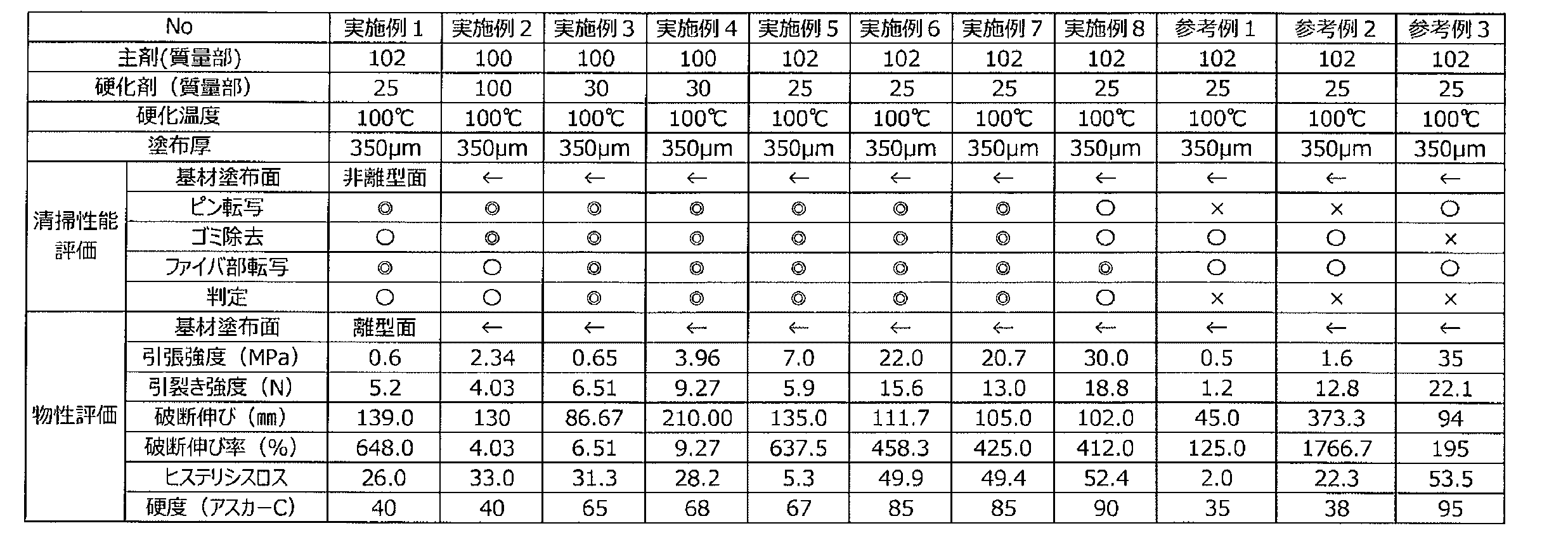
また、各実施例に係る清掃体CTを実際に清掃具10に組み込んで使用したところ、清掃具の動作を阻害することなく、光コネクタの端面の汚染体を容易に捕集可能であることが確かめられた。
10 清掃具
100 ハウジング
140 コイルバネ
200 供給リール
300 巻取リール
410 清掃ヘッド
420 ヘッド保持体
500 巻取制御体
CT 清掃体
RL 樹脂層
MF 最大前方位置
MR 最大後方位置
100 ハウジング
140 コイルバネ
200 供給リール
300 巻取リール
410 清掃ヘッド
420 ヘッド保持体
500 巻取制御体
CT 清掃体
RL 樹脂層
MF 最大前方位置
MR 最大後方位置
Claims (9)
- 汚染体を保持可能な層を有し光コネクタの端面を清掃するための清掃体が供給可能に保持される供給保持体が収納される本体と、
前記本体から供給された清掃体が位置づけられる清掃ヘッドであって、前記本体に対して一定の保持位置に保持された清掃ヘッドと、
前記光コネクタと係合可能であり、かつ、前記光コネクタと係合した状態を維持しつつ前記清掃ヘッドに対して第1の位置から前記第1の位置と異なる第2の位置まで変位可能な制御体と、
前記制御体が前記第1の位置から前記第2の位置まで変位する動作を清掃体に伝達して清掃体を変位させて前記清掃ヘッドに供給する供給機構と、を備え、
前記制御体が前記第1の位置に位置するときには、前記清掃ヘッドは前記光コネクタの端面から離隔し、
前記制御体が前記第1の位置から前記第2の位置に変位する間に、前記供給機構によって清掃体が変位し、
前記制御体が前記第2の位置に位置するときには、前記清掃ヘッドが前記光コネクタの端面と接触する光コネクタ用清掃具。 - 前記本体に対して一定の位置に設けられ一定の形状を有するヘッド保持体を、更に備え、
前記清掃ヘッドは、前記ヘッド保持体の一定の位置に設けられて、前記本体に対して前記保持位置に保持される請求項1に記載の光コネクタ用清掃具。 - 前記ヘッド保持体は、前記本体から供給される清掃体を前記清掃ヘッドに向かって直線状に案内する請求項2に記載の光コネクタ用清掃具。
- 前記清掃ヘッドに供給された清掃体を回収して保持する回収保持体をさらに備え、
前記供給機構は、前記制御体の動作を前記回収保持体を伝達して前記回収保持体に清掃体を回収させ、清掃体の回収に伴って清掃体を牽引して、前記本体から前記清掃ヘッドに清掃体を供給する請求項3に記載の光コネクタ用清掃具。 - 前記制御体を第1の位置に戻すための付勢力を前記制御体に加える付勢力発生手段を更に備え、
前記付勢力発生手段は、前記供給保持体に隣接し清掃体の移動経路と異なる位置に配置されている請求項1に記載の光コネクタ用清掃具。 - 前記ヘッド保持体は、前記清掃体と向かい合う面に少なくとも1つの貫通孔を有する、請求項3に記載の光コネクタ用清掃具。
- 前記ヘッド保持体は、フィラーを含む、請求項3に記載の光コネクタ用清掃具。
- 前記回収保持体は、前記清掃体を巻き取って回収する回転保持体であり、間隙を有して互いに向かい合う2つのリール枠であって、巻き取った前記清掃体を前記間隙に保持する2つのリール枠を有する、請求項4に記載の光コネクタ用清掃具。
- 前記清掃体は、ポリウレタン樹脂を含む樹脂層を有し、
前記樹脂層は、引張強度が0.6~30MPaであり、アスカーC硬度が40~90であり、ヒステリシスロスが5~53である、請求項1に記載の光コネクタ用清掃具。
Priority Applications (3)
| Application Number | Priority Date | Filing Date | Title |
|---|---|---|---|
| JP2020549120A JPWO2020059853A1 (ja) | 2018-09-21 | 2019-09-20 | 光コネクタ用清掃具 |
| EP19863521.1A EP3855224A4 (en) | 2018-09-21 | 2019-09-20 | TOOL FOR CLEANING AN OPTICAL PLUG |
| US17/277,489 US20220035106A1 (en) | 2018-09-21 | 2019-09-20 | Optical connector cleaning tool |
Applications Claiming Priority (2)
| Application Number | Priority Date | Filing Date | Title |
|---|---|---|---|
| JP2018177413 | 2018-09-21 | ||
| JP2018-177413 | 2018-09-21 |
Publications (1)
| Publication Number | Publication Date |
|---|---|
| WO2020059853A1 true WO2020059853A1 (ja) | 2020-03-26 |
Family
ID=69887211
Family Applications (1)
| Application Number | Title | Priority Date | Filing Date |
|---|---|---|---|
| PCT/JP2019/036962 Ceased WO2020059853A1 (ja) | 2018-09-21 | 2019-09-20 | 光コネクタ用清掃具 |
Country Status (5)
| Country | Link |
|---|---|
| US (1) | US20220035106A1 (ja) |
| EP (1) | EP3855224A4 (ja) |
| JP (1) | JPWO2020059853A1 (ja) |
| TW (1) | TW202021679A (ja) |
| WO (1) | WO2020059853A1 (ja) |
Cited By (4)
| Publication number | Priority date | Publication date | Assignee | Title |
|---|---|---|---|---|
| WO2022004096A1 (ja) * | 2020-07-01 | 2022-01-06 | 株式会社フジクラ | 清掃工具 |
| WO2022208943A1 (ja) * | 2021-03-29 | 2022-10-06 | 株式会社フジクラ | 清掃工具及び清掃方法 |
| TWI810576B (zh) * | 2020-06-01 | 2023-08-01 | 日商巴川製紙所股份有限公司 | 被安裝體安裝構造及被安裝體安裝方法 |
| WO2025249012A1 (ja) * | 2024-05-31 | 2025-12-04 | 株式会社フジクラ | 光コネクタ清掃工具 |
Families Citing this family (1)
| Publication number | Priority date | Publication date | Assignee | Title |
|---|---|---|---|---|
| CN116379702B (zh) * | 2023-02-28 | 2025-07-18 | 深圳市奥兰特机械有限公司 | 一种光学镜头生产用的冷热一体机 |
Citations (9)
| Publication number | Priority date | Publication date | Assignee | Title |
|---|---|---|---|---|
| JP2001316448A (ja) | 2000-05-01 | 2001-11-13 | Polysis:Kk | 軟質組成物 |
| US20030098045A1 (en) * | 2001-11-29 | 2003-05-29 | 3M Innovative Properties Company | Article and process for cleaning optical surfaces |
| US6758605B1 (en) * | 2003-02-21 | 2004-07-06 | Telops Inc. | Cleaning device and method for optical connectors |
| JP2012056985A (ja) | 2010-09-06 | 2012-03-22 | Nitto Denko Corp | 発泡粘着体 |
| JP2014035489A (ja) | 2012-08-09 | 2014-02-24 | Fujikura Ltd | 光コネクタ清掃工具及び光コネクタ清掃方法 |
| JP2014081445A (ja) * | 2012-10-15 | 2014-05-08 | Olympus Corp | 光コネクタ清掃装置、及び光コネクタの清掃方法 |
| WO2014141405A1 (ja) * | 2013-03-13 | 2014-09-18 | エヌ・ティ・ティ・アドバンステクノロジ株式会社 | 光コネクタ用清掃具 |
| JP6498814B1 (ja) * | 2018-04-12 | 2019-04-10 | 株式会社フジクラ | 光コネクタ清掃工具及び光コネクタの清掃方法 |
| WO2019176404A1 (ja) * | 2018-03-12 | 2019-09-19 | 株式会社巴川製紙所 | 光コネクタ端面クリーナ |
Family Cites Families (5)
| Publication number | Priority date | Publication date | Assignee | Title |
|---|---|---|---|---|
| DE1280682B (de) * | 1965-01-23 | 1968-10-17 | Collo Rheincollodium Koeln G M | Mittel zum Dekontaminieren der Haut, insbesondere der menschlichen Haut |
| JP2003200116A (ja) * | 2002-01-09 | 2003-07-15 | Ntt Advanced Technology Corp | 光コネクタ用清掃具 |
| JP5525628B2 (ja) * | 2012-01-19 | 2014-06-18 | エヌ・ティ・ティ・アドバンステクノロジ株式会社 | 光コネクタ用清掃具 |
| JP6231440B2 (ja) * | 2014-06-13 | 2017-11-15 | 株式会社フジクラ | 光コネクタの清掃工具 |
| US20180088285A1 (en) * | 2016-09-29 | 2018-03-29 | Commscope Technologies Llc | Fiber end face cleaning tapes with micro-capsule cleaning agents; and methods |
-
2019
- 2019-09-20 TW TW108134038A patent/TW202021679A/zh unknown
- 2019-09-20 EP EP19863521.1A patent/EP3855224A4/en not_active Withdrawn
- 2019-09-20 WO PCT/JP2019/036962 patent/WO2020059853A1/ja not_active Ceased
- 2019-09-20 JP JP2020549120A patent/JPWO2020059853A1/ja active Pending
- 2019-09-20 US US17/277,489 patent/US20220035106A1/en not_active Abandoned
Patent Citations (10)
| Publication number | Priority date | Publication date | Assignee | Title |
|---|---|---|---|---|
| JP2001316448A (ja) | 2000-05-01 | 2001-11-13 | Polysis:Kk | 軟質組成物 |
| US20030098045A1 (en) * | 2001-11-29 | 2003-05-29 | 3M Innovative Properties Company | Article and process for cleaning optical surfaces |
| US6758605B1 (en) * | 2003-02-21 | 2004-07-06 | Telops Inc. | Cleaning device and method for optical connectors |
| JP2012056985A (ja) | 2010-09-06 | 2012-03-22 | Nitto Denko Corp | 発泡粘着体 |
| JP2014035489A (ja) | 2012-08-09 | 2014-02-24 | Fujikura Ltd | 光コネクタ清掃工具及び光コネクタ清掃方法 |
| JP2014081445A (ja) * | 2012-10-15 | 2014-05-08 | Olympus Corp | 光コネクタ清掃装置、及び光コネクタの清掃方法 |
| WO2014141405A1 (ja) * | 2013-03-13 | 2014-09-18 | エヌ・ティ・ティ・アドバンステクノロジ株式会社 | 光コネクタ用清掃具 |
| JP5955453B2 (ja) | 2013-03-13 | 2016-07-20 | エヌ・ティ・ティ・アドバンステクノロジ株式会社 | 光コネクタ用清掃具 |
| WO2019176404A1 (ja) * | 2018-03-12 | 2019-09-19 | 株式会社巴川製紙所 | 光コネクタ端面クリーナ |
| JP6498814B1 (ja) * | 2018-04-12 | 2019-04-10 | 株式会社フジクラ | 光コネクタ清掃工具及び光コネクタの清掃方法 |
Non-Patent Citations (1)
| Title |
|---|
| See also references of EP3855224A4 |
Cited By (13)
| Publication number | Priority date | Publication date | Assignee | Title |
|---|---|---|---|---|
| TWI810576B (zh) * | 2020-06-01 | 2023-08-01 | 日商巴川製紙所股份有限公司 | 被安裝體安裝構造及被安裝體安裝方法 |
| JPWO2022004096A1 (ja) * | 2020-07-01 | 2022-01-06 | ||
| CN115362400B (zh) * | 2020-07-01 | 2025-01-03 | 株式会社藤仓 | 清扫工具 |
| WO2022004096A1 (ja) * | 2020-07-01 | 2022-01-06 | 株式会社フジクラ | 清掃工具 |
| CN115362400A (zh) * | 2020-07-01 | 2022-11-18 | 株式会社藤仓 | 清扫工具 |
| US20230180377A1 (en) * | 2020-07-01 | 2023-06-08 | Fujikura Ltd. | Cleaning tool |
| JP7429781B2 (ja) | 2020-07-01 | 2024-02-08 | 株式会社フジクラ | 清掃工具 |
| JPWO2022208943A1 (ja) * | 2021-03-29 | 2022-10-06 | ||
| JP7429824B2 (ja) | 2021-03-29 | 2024-02-08 | 株式会社フジクラ | 清掃工具及び清掃方法 |
| CN116456884A (zh) * | 2021-03-29 | 2023-07-18 | 株式会社藤仓 | 清扫工具以及清扫方法 |
| WO2022208943A1 (ja) * | 2021-03-29 | 2022-10-06 | 株式会社フジクラ | 清掃工具及び清掃方法 |
| US12415208B2 (en) | 2021-03-29 | 2025-09-16 | Fujikura Ltd. | Cleaning tool and cleaning method |
| WO2025249012A1 (ja) * | 2024-05-31 | 2025-12-04 | 株式会社フジクラ | 光コネクタ清掃工具 |
Also Published As
| Publication number | Publication date |
|---|---|
| EP3855224A1 (en) | 2021-07-28 |
| TW202021679A (zh) | 2020-06-16 |
| US20220035106A1 (en) | 2022-02-03 |
| EP3855224A4 (en) | 2022-06-15 |
| JPWO2020059853A1 (ja) | 2021-09-30 |
Similar Documents
| Publication | Publication Date | Title |
|---|---|---|
| WO2020059853A1 (ja) | 光コネクタ用清掃具 | |
| JP5905464B2 (ja) | ポリウレタンフォーム | |
| US20230176295A1 (en) | Optical connector end surface cleaner | |
| CN108884314B (zh) | 单液型水性树脂组合物及纤维层叠体 | |
| CN103890032A (zh) | 湿气固化型聚氨酯热熔树脂组合物、胶粘剂及物品 | |
| JPWO2012124389A1 (ja) | エネルギー線硬化型粘着剤および粘着シート | |
| JP7462577B2 (ja) | 清掃具 | |
| US20220317385A1 (en) | Optical connector cleaning tool | |
| EP0535115A4 (en) | Composites | |
| US9863088B2 (en) | Airbag base fabric coating material, airbag base fabric, and method for manufacturing the same | |
| US20200064754A1 (en) | Laminate and conductive roller | |
| KR101969800B1 (ko) | 탄소소재를 이용한 자동차 충격보호용 복합소재 필름 제조방법 | |
| JP7148759B2 (ja) | 被取付体取付構造及び被取付体取付方法 | |
| KR20220066139A (ko) | 우레탄 수지 수분산체, 합성 피혁, 및, 합성 피혁의 제조 방법 | |
| CN114207201A (zh) | 具有含有机硅的嵌段共聚物芯的芯-鞘丝 | |
| KR102530192B1 (ko) | 점착 테이프 | |
| JP2021120712A (ja) | 光伝送用媒体清掃具 | |
| JP5729720B2 (ja) | 研磨布及び該研磨布を用いた研磨方法 | |
| JP2010199538A (ja) | 太陽電池モジュール用止水テープ | |
| WO2021153645A1 (ja) | 光コネクタ用清掃具 | |
| TW200918633A (en) | Rubbing sheet for winding and adhering roller | |
| WO2022224081A1 (en) | Laminate for application to wallpaper and article using same | |
| JP2024125779A (ja) | 通信機器用の清掃具およびその清掃方法 | |
| CN117355590A (zh) | 双组分型氨基甲酸酯系粘接剂组合物 | |
| WO2020009234A1 (ja) | 導電性ローラ及び画像形成装置 |
Legal Events
| Date | Code | Title | Description |
|---|---|---|---|
| 121 | Ep: the epo has been informed by wipo that ep was designated in this application |
Ref document number: 19863521 Country of ref document: EP Kind code of ref document: A1 |
|
| ENP | Entry into the national phase |
Ref document number: 2020549120 Country of ref document: JP Kind code of ref document: A |
|
| NENP | Non-entry into the national phase |
Ref country code: DE |
|
| ENP | Entry into the national phase |
Ref document number: 2019863521 Country of ref document: EP Effective date: 20210421 |