WO2020065758A1 - 誘導加熱調理器 - Google Patents
誘導加熱調理器 Download PDFInfo
- Publication number
- WO2020065758A1 WO2020065758A1 PCT/JP2018/035676 JP2018035676W WO2020065758A1 WO 2020065758 A1 WO2020065758 A1 WO 2020065758A1 JP 2018035676 W JP2018035676 W JP 2018035676W WO 2020065758 A1 WO2020065758 A1 WO 2020065758A1
- Authority
- WO
- WIPO (PCT)
- Prior art keywords
- top plate
- induction heating
- region
- heating cooker
- cooling device
- Prior art date
- Legal status (The legal status is an assumption and is not a legal conclusion. Google has not performed a legal analysis and makes no representation as to the accuracy of the status listed.)
- Ceased
Links
Images










Classifications
-
- H—ELECTRICITY
- H05—ELECTRIC TECHNIQUES NOT OTHERWISE PROVIDED FOR
- H05B—ELECTRIC HEATING; ELECTRIC LIGHT SOURCES NOT OTHERWISE PROVIDED FOR; CIRCUIT ARRANGEMENTS FOR ELECTRIC LIGHT SOURCES, IN GENERAL
- H05B6/00—Heating by electric, magnetic or electromagnetic fields
- H05B6/02—Induction heating
- H05B6/10—Induction heating apparatus, other than furnaces, for specific applications
- H05B6/12—Cooking devices
- H05B6/1209—Cooking devices induction cooking plates or the like and devices to be used in combination with them
Definitions
- the present invention relates to an induction heating cooker provided with a top plate on which a cooking vessel is placed.
- an electromagnetic apparatus including a loading unit for loading cooking utensils, and a heating device provided below the loading unit and heating the cooking utensils loaded on the loading unit by electromagnetic induction.
- a cooker has been proposed (see Patent Document 1).
- the electromagnetic cooker includes a cooling device that is in contact with the loading unit from a direction opposite to the direction in which the cooking utensils are loaded, and cools the cooking utensils loaded on the loading unit.
- the loading section is made of, for example, crystallized glass.
- Patent Literature 1 cools the cooking utensil by absorbing the heat transferred from the cooking utensil to the loading unit by a cooling device in contact with the lower surface of the loading unit. For this reason, there is a problem that it takes more time to cool the cooking container by the cooling device than to heat the cooking container by the electromagnetic induction action.
- the present invention has been made to solve the above-described problems, and an object of the present invention is to provide an induction heating cooker capable of improving a cooling speed of a cooking vessel placed on a top plate.
- An induction heating cooker includes a top plate that is formed in a flat plate shape and includes a first region and a second region having a higher thermal conductivity than the first region, and a first region of the top plate.
- a heating coil that is disposed below and induction-heats the cooking container placed in the first region; and a cooking container that is disposed below the second region of the top plate and placed in the second region.
- a cooling device for cooling.
- the present invention includes a heating coil for inductively heating the cooking vessel placed on the first region of the top plate, and a cooling device for cooling the cooking vessel placed on the second region of the top plate.
- the second region of the top plate has a higher thermal conductivity than the first region. For this reason, compared with the case where the thermal conductivity of the top plate above the cooling device is the thermal conductivity of the first region, the cooling speed of the cooking container by the cooling device can be improved.
- FIG. 2 is an exploded perspective view showing the induction heating cooker according to Embodiment 1. It is a top view explaining the 1st field and the 2nd field of the induction heating cooker concerning Embodiment 1.
- FIG. 2 is a block diagram showing a configuration of the induction heating cooker according to Embodiment 1. It is a top view which shows the cooling device of the induction heating cooker concerning Embodiment 1. It is a side view which shows typically the structure of the cooling device of the induction heating cooker which concerns on Embodiment 1. It is a side view which shows typically the installation state of the cooling device of the induction heating cooker which concerns on Embodiment 1.
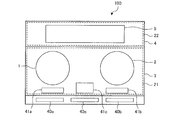
- FIG. 1 is a plan view showing an induction heating cooker according to Embodiment 1.
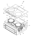
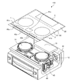
- FIG. 2 is an exploded perspective view showing the induction heating cooker according to the first embodiment.
- a top plate 20 formed in a flat plate shape and on which the cooking container 6 such as a pot is placed is provided at an upper portion of the induction heating cooker 100.
- the top plate 20 has a first top plate 3 and a second top plate 4.
- the first top plate 3 is arranged adjacent to the second top plate 4.
- the first top plate 3 is arranged on the near side of the top plate 20.
- the second top plate 4 is arranged on the back side of the top plate 20.
- the first top plate 3 and the second top plate 4 are joined in the same plane.
- the first top plate 3 is made of a material capable of causing an eddy current to flow through the cooking vessel 6 for induction heating without hindering a high-frequency magnetic field from the heating coil 11 described later.
- the first top plate 3 is made of heat-resistant tempered glass or crystallized glass.
- the second top plate 4 is made of a material having a higher thermal conductivity than the first top plate 3.
- the second top plate 4 is made of aluminum, copper, aluminum nitride, silicon, stainless steel, alumina, or the like.
- the thermal conductivity of crystallized glass is 1 [W / mK].
- the thermal conductivity of aluminum is 236 [W / mK].
- the thermal conductivity of copper is 398 [W / mK].
- the thermal conductivity of aluminum nitride is 285 [W / mK].
- the thermal conductivity of silicon is 168 [W / mK].
- the thermal conductivity of stainless steel is 16.7 to 20.9 [W / mK].
- the thermal conductivity of alumina is 30 [W / mK]. That is, the second top plate 4 has, for example, approximately 16 to 400 times higher thermal conductivity than the first top plate 3.
- the first top plate 3 is formed with a first heating port 1 and a second heating port 2 indicating a rough mounting position of the cooking vessel 6 corresponding to a heating range of the heating coil 11 and the heating coil 12, respectively. I have.
- the first heating port 1 and the second heating port 2 are, for example, circular displays corresponding to the outer diameters of the heating coils 11 and 12.
- the first heating port 1 and the second heating port 2 are formed by applying or printing a paint on the first top plate 3.
- the heating coil 11 and the heating coil 12 are configured by winding a conductive wire made of a metal coated with an insulating film.
- a conductive wire for example, any metal such as copper or aluminum can be used.
- a cooling device 13 for cooling the cooking vessel 6 placed on the second top plate 4 is provided below the second top plate 4, a cooling device 13 for cooling the cooking vessel 6 placed on the second top plate 4 is provided.
- the cooling device 13 is provided at a substantially central position in the lateral direction of the second top plate 4 on the back side of the induction heating cooker 100.
- the second top plate 4 is provided with a cooling port 5 that indicates a rough mounting position of the cooking vessel 6 corresponding to a cooling range of the cooling device 13.
- the cooling port 5 is formed, for example, above the cooling device 13 and is a rectangular display corresponding to the outer diameter shape of the cooling device 13.
- the cooling port 5 is formed by applying or printing a paint on the second top plate 4 or the like.
- the shape of the cooling port 5 is not limited to a rectangle.
- the cooling port 5 only needs to indicate a rough range in which the cooking container 6 placed on the second top plate 4 can be cooled by the cooling device 13.
- the shape of the cooling port 5 may be circular, elliptical, or square.
- a plurality of cooling ports 5 may be provided for one cooling device 13.
- a plurality of cooling devices 13 may be provided, and a plurality of cooling ports 5 may be provided corresponding to the respective cooling ranges.
- one cooling port 5 may be provided for a plurality of cooling devices 13.
- the cooling device 13 includes, for example, a Peltier element.
- the cooling device 13 cools the cooking container 6 placed on the second top plate 4 by cooling the second top plate 4 from the lower surface side. Details of the cooling device 13 will be described later.
- FIG. 3 is a plan view illustrating a first region and a second region of the induction heating cooker according to the first embodiment.
- the top plate 20 includes a first region 21 and a second region 22.
- the second region 22 is a region having a higher thermal conductivity than the first region 21. That is, the second top plate 4, which is a material having a higher thermal conductivity than the first top plate 3, forms the second region 22 in the top plate 20. Further, the first top plate 3 forms a first region 21 in the top plate 20.
- the heating coil 11 and the heating coil 12 heat the cooking container 6 placed on the first region 21 of the top plate 20 by induction.
- the cooling device 13 cools the cooking container 6 placed on the second region 22 of the top plate 20.
- FIG. 1 and FIG. 2 are referred to again.
- An operation unit 40a and an operation unit 40b are provided on the front side of the top plate 20 as input devices for setting input power, a cooking menu, and the like when heating the cooking container 6 and the like with the heating coil 11 and the heating coil 12. Have been.
- a display unit 41a and a display unit 41b that display the operation state of each heating coil, the contents of the input operation from the operation unit 40a and the operation unit 40b, and the like are provided as notification means. Is provided.
- An operation unit 40c is provided in the center of the front side of the top plate 20 as an input device for setting input power and a cooking menu when the cooling device 13 cools the cooking container 6 and the like.
- a display unit 41c that displays the operating state of the cooling device 13, the content of the input operation from the operation unit 40c, and the like is provided as a notification unit near the operation unit 40c.
- the operation units 40a to 40c are configured by mechanical switches such as a push switch and a tact switch, touch switches that detect an input operation based on a change in capacitance of an electrode, and the like.
- the display units 41a to 41c are configured by, for example, LCDs and LEDs. Note that an operation display unit in which the operation unit 40a and the display unit 41a are integrally configured may be used. Further, the operation display section may be configured such that the operation section 40b and the display section 41b are integrally configured. Further, the operation display unit may be configured such that the operation unit 40c and the display unit 41c are integrally formed.
- the operation display unit includes, for example, a touch panel in which a touch switch is arranged on the upper surface of the LCD. Note that LCD is an abbreviation for Liquid Crystal Device. LED is an abbreviation of Light ⁇ Emitting ⁇ Diode.
- the numbers of the operation units 40a to 40c and the display units 41a to 41c are not limited to the configuration in which one is provided for each of the heating coil 11, the heating coil 12, and the cooling device 13 as described above.
- one operation unit 40 and one display unit 41 may be provided as a common one of the heating coil 11, the heating coil 12, and the cooling device 13.
- a drive circuit 46 for driving the heating coil 11, the heating coil 12, and the cooling device 13, and a control device 45 for controlling the operation of the entire induction heating cooker 100 including the drive circuit 46 are provided.
- the control device 45 is configured by dedicated hardware or a CPU that executes a program stored in a memory.
- CPU is an abbreviation of Central Processing Unit.
- the CPU is also referred to as a central processing unit, a processing unit, an arithmetic unit, a microprocessor, a microcomputer, or a processor.
- control device 45 When the control device 45 is dedicated hardware, the control device 45 corresponds to, for example, a single circuit, a composite circuit, an ASIC, an FPGA, or a combination thereof. Each of the function units realized by the control device 45 may be realized by individual hardware, or each function unit may be realized by one piece of hardware.
- the ASIC is an abbreviation of Application ⁇ Specific ⁇ Integrated ⁇ Circuit.
- FPGA is an abbreviation of Field-Programmable Gate Array.
- each function executed by the control device 45 is realized by software, firmware, or a combination of software and firmware.
- Software and firmware are described as programs and stored in a memory.
- the CPU realizes each function of the control device 45 by reading and executing the program stored in the memory.
- the memory is, for example, a nonvolatile or volatile semiconductor memory such as a RAM, a ROM, a flash memory, an EPROM, and an EEPROM.
- RAM is an abbreviation for Random ⁇ Access ⁇ Memory.
- ROM is an abbreviation of Read ⁇ Only ⁇ Memory.
- EPROM is an abbreviation of Erasable ⁇ Programmable ⁇ Read ⁇ Only ⁇ Memory.
- EEPROM is an abbreviation of Electrically Erasable Programmable Read-Only Memory.
- a temperature sensor 42 (shown by a broken line in FIG. 1) is provided on the lower surface of the second top plate 4.
- the temperature sensor 42 is composed of, for example, a thermistor.
- the temperature sensor 42 is disposed, for example, near the cooling device 13.
- the temperature sensor 42 detects the temperature by the heat transferred from the cooking vessel 6 to the second top plate 4.
- the control device 45 controls the cooling device 13 according to the temperature detected by the temperature sensor 42.
- a blower 60 is provided inside the induction heating cooker 100.
- the blower 60 draws in air outside the main body of the induction heating cooker 100 into the main body through an air inlet (not shown), and supplies cooling air to the inside of the main body.
- the cooling air supplied into the main body cools the components inside the main body and the cooling device 13 and is then exhausted to the outside of the main body through an exhaust port (not shown).
- FIG. 4 is a block diagram showing a configuration of the induction heating cooker according to Embodiment 1.
- the drive of the heating coil 11 is controlled by a drive circuit 46a.
- the drive of the heating coil 12 is controlled by a drive circuit 46b.
- the drive of the cooling device 13 is controlled by a drive circuit 46c.
- the drive circuits 46a and 46b include an inverter circuit.
- the drive circuit 46a and the drive circuit 46b convert the AC power supplied from the AC power supply into high-frequency AC power of about 20 kHz to 100 kHz, and output the high-frequency AC power to the heating coil 11 and the heating coil 12, respectively.
- Drive circuit 46c includes a DC power supply circuit.
- the drive circuit 46c converts the AC power supplied from the AC power supply into an arbitrary DC power and outputs the DC power to the cooling device 13.
- the control device 45 controls the operations of the drive circuits 46a to 46c and the blower 60 according to the inputs from the operation units 40a to 40c and the temperature sensor 42.
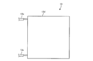
- FIG. 5 is a plan view showing a cooling device of the induction heating cooker according to the first embodiment.
- FIG. 6 is a side view schematically illustrating a configuration of a cooling device of the induction heating cooker according to the first embodiment.
- the cooling device 13 includes a plurality of P-type thermoelectric semiconductors 13a, a plurality of N-type thermoelectric semiconductors 13b, a plurality of electrodes 13c, and a pair of insulating members 13d.
- the pair of insulating members 13d is made of, for example, an insulating material such as ceramic.
- the pair of insulating members 13d is formed in a flat plate shape.
- the pair of insulating members 13d are arranged to face each other.
- the plurality of P-type thermoelectric semiconductors 13a and the plurality of N-type thermoelectric semiconductors 13b are arranged between the pair of insulating members 13d.
- the P-type thermoelectric semiconductors 13a and the N-type thermoelectric semiconductors 13b are arranged alternately.
- the electrode 13c electrically connects the adjacent P-type thermoelectric semiconductor 13a and N-type thermoelectric semiconductor 13b.
- a lead wire 13e is connected to an end of the electrode 13c. The other end of the lead wire 13e is connected to the drive circuit 46c, and a DC voltage from the drive circuit 46c is applied.
- the P-type thermoelectric semiconductor 13a, the N-type thermoelectric semiconductor 13b and the electrode 13c constitute a Peltier device.
- a direct current flows through the electrode 13c, heat or heat is generated at the contact surface between the P-type thermoelectric semiconductor 13a and the N-type thermoelectric semiconductor 13b and the electrode 13c. Accordingly, one of the pair of insulating members 13d that becomes the cold side is cooled, and the other of the pair of insulating members 13d that becomes the hot side is heated.
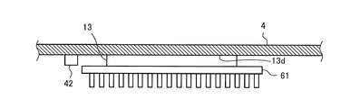
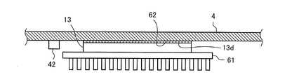
- FIG. 7 is a side view schematically showing an installation state of the cooling device of the induction heating cooker according to Embodiment 1.
- the cooling device 13 is disposed in close contact with the lower surface of the second top plate 4 such that the insulating member 13 d serving as a cold side faces the second top plate 4.
- a radiating means 61 is disposed in close contact with the other of the pair of insulating members 13d which is the hot side.
- the heat radiating means 61 is constituted by, for example, a heat radiating fin.
- the heat radiating unit 61 is supplied with cooling air from the blower 60, and radiates heat from the insulating member 13d serving as a hot side.
- a blower that blows cooling air to the heat radiating means 61 may be further provided beside or below the heat radiating means 61. It is preferable to apply thermal grease, an adhesive, or the like to the joint surface between the cooling device 13 and the second top plate 4 and the joint surface between the cooling device 13 and the heat radiating means 61 so that the air does not intervene. desirable.
- the user places the cooking container 6 such as a pot on the first heating port 1 or the second heating port 2 of the first top plate 3.
- the user performs an input operation for starting heating by using the operation unit 40a.
- the control device 45 controls the operation of the drive circuit 46a according to the power set by an input operation from the operation unit 40a. For example, the controller 45 varies the frequency of the high-frequency current supplied from the drive circuit 46a to the heating coil 11 according to the set power.
- the user places the cooking vessel 6 such as a pot on the cooling port 5 of the second top plate 4. Next, the user performs an input operation to start cooling using the operation unit 40c.
- the control device 45 controls the operation of the drive circuit 46c according to the power set by the input operation from the operation unit 40c.
- the input operation from the operation unit 40c includes, for example, an input operation of a cooling temperature level of three stages of “weak”, “medium”, and “strong”, or an input operation of a set temperature value of the cooking container 6.
- the control device 45 controls the operation of the drive circuit 46c according to the input operation from the operation unit 40c. For example, the control device 45 controls on / off of DC power supplied to the cooling device 13 according to the cooling temperature level. Specifically, when the input operation is “strong”, the control device 45 always turns on the supply of the DC power from the drive circuit 46c to the cooling device 13. When the input operation is “middle”, the control device 45 periodically switches the supply of the DC power from the drive circuit 46c to the cooling device 13 between an on state and an off state. When the input operation is “weak”, the control device 45 controls the supply of the DC power from the drive circuit 46c to the cooling device 13 periodically so that the OFF state is longer than the input operation is “medium”. Switch between the on state and the off state.
- the control device 45 controls the cooling device 13 so that the temperature detected by the temperature sensor 42 becomes the set temperature. Specifically, when the temperature detected by temperature sensor 42 is lower than the set temperature, controller 45 turns on the supply of DC power from drive circuit 46c to cooling device 13. When the temperature detected by the temperature sensor 42 is equal to or higher than the set temperature, the control device 45 turns off the supply of DC power from the drive circuit 46c to the cooling device 13.
- the control of the cooling device 13 by the control device 45 is not limited to the above-described control, and any temperature control can be applied.
- the control device 45 may perform control to increase the on-duty ratio of the drive circuit 46c as the temperature difference between the set temperature and the temperature detected by the temperature sensor 42 increases.
- the above-described heating cooking and cooling cooking can be performed in parallel with each other, or can be performed continuously with each other.
- the user may place two cooking containers 6 each of the first heating port 1 and the cooling port 5 and operate the heating cooking by the heating coil 11 and the cooling cooking by the cooling device 13 in parallel. good.
- the user places one cooking container 6 in the first heating port 1 and causes the heating coil 11 to perform heating cooking, and then cools the cooking container 6 placed in the first heating port 1. It may be moved to the mouth 5 to perform cooling cooking by the cooling device 13.
- the heating coil 11 arranged below the first region 21 of the top plate 20 and the cooling device 13 arranged below the second region 22 of the top plate 20 Prepare.
- the top plate 20 is configured such that the second region 22 has a higher thermal conductivity than the first region 21.
- the cooling speed of the cooking container 6 by the cooling device 13 can be improved. Therefore, the cooking time in cooling cooking of the cooking container 6 can be shortened.
- the time required to reduce the temperature of the food in the cooking container 6 to the refrigerator after heating and cooking can be shortened, the proliferation of bacteria in the food can be suppressed as compared with natural cooling. it can.
- heating cooking and cooling cooking can be performed in parallel or continuously, cooperative cooking of cooling and heating of the food in the cooking container 6 becomes possible.
- cooling cooking after heating cooking the infiltration of taste into the food in the cooking container 6 can be improved, and the taste of the food can be increased.
- the top plate 20 is formed in a flat plate shape. For this reason, after heating and cooking the cooking vessel 6 placed on the first area 21 of the top plate 20, the cooking vessel 6 is slid without lifting, from the first area 21 of the top plate 20 to the second area 22.
- the cooking container 6 can be easily moved. Therefore, cooperation between heating cooking and cooling cooking becomes easy.
- the top plate 20 has a first top plate 3 forming the first region 21 and a second region 22 and has a higher thermal conductivity than the first top plate 3. And a second top plate 4. Therefore, the cooling rate of the cooking vessel 6 placed on the second top plate 4 is improved as compared with the case where the thermal conductivity of the second top plate 4 is the thermal conductivity of the first top plate 3. Can be. Therefore, the cooking time in cooling cooking of the cooking container 6 can be shortened.
- first top plate 3 and the second top plate 4 are joined in the same plane. For this reason, after the cooking vessel 6 placed on the first top plate 3 is heated and cooked, the cooking vessel 6 is easily moved from the first top plate 3 to the second top plate 4 by sliding without lifting the cooking vessel 6. Can be moved. Therefore, cooperation between heating cooking and cooling cooking becomes easy.
- the first top plate 3 is made of, for example, heat-resistant tempered glass or crystallized glass.
- the second top plate 4 is made of, for example, aluminum, copper, aluminum nitride, silicon, stainless steel, alumina, or the like.
- heat-resistant tempered glass or crystallized glass is more expensive than aluminum, copper, aluminum nitride, silicon, stainless steel, or alumina. For this reason, compared with the case where the entire top plate 20 is made of heat-resistant tempered glass or crystallized glass, the amount of material used such as heat-resistant tempered glass or crystallized glass can be reduced, and Cost can be reduced.
- the second top plate 4 is arranged adjacent to the first top plate 3. For this reason, after heating and cooking the cooking container 6 placed on the first top plate 3, the cooking container 6 can be easily moved from the first top plate 3 to the second top plate 4. Therefore, cooperation between heating cooking and cooling cooking becomes easy.
- the top plate 20 is provided with the cooling port 5 that indicates the mounting position of the cooking vessel 6 above the cooling device 13. For this reason, the user can easily grasp the placement position of the cooking container 6 in the cooling cooking. Therefore, the cooking container 6 can be easily placed at a position where the cooling cooking by the cooling device 13 can be performed, and the cooling of the cooking container 6 can be efficiently performed.
- the temperature sensor 42 disposed on the lower surface of the second region 22 of the top plate 20 and the control device 45 for controlling the cooling device 13 according to the temperature detected by the temperature sensor 42 Is provided. For this reason, compared with the case where the thermal conductivity of the second region 22 of the top plate 20 is the thermal conductivity of the first region 21, the temperature error of the temperature detection of the cooking vessel 6 and the time delay of the temperature change are reduced. be able to. Therefore, it is possible to quickly and accurately detect the temperature of the cooking vessel 6 during cooling cooking, and to perform accurate temperature control based on a detection signal from the temperature sensor 42.
- the first embodiment includes the control device 45 that controls the cooling device 13 according to an input operation from the operation unit 40. Therefore, the operation of the cooling device 13 such as the start and stop of the cooling cooking can be easily set.
- a control device 45 for controlling the cooling device 13 so that the temperature detected by the temperature sensor 42 becomes the set temperature is provided. Therefore, accurate temperature control can be performed in cooling cooking based on the detection signal from the temperature sensor 42.
- FIG. 8 is a side view schematically illustrating an installation state of a cooling device in a first modification of the induction heating cooker according to the first embodiment.
- the cooling device 13 may be arranged on the lower surface of the top plate 20 in close contact with the elastic body 62 therebetween. That is, in the cooling device 13, the elastic body 62 is interposed between the insulating member 13 d serving as a cold side and the second top plate 4.
- the elastic body 62 is a material having a higher thermal conductivity than the first top plate 3.
- the elastic body 62 is made of, for example, silicon or the like.
- the cooling device 13 and the second top plate 4 can be brought into close contact with each other so that no air layer is interposed between the cooling device 13 and the second top plate 4. Therefore, the cooling efficiency of the cooking container 6 by the cooling device 13 can be improved, and the cooling speed of the cooking container 6 can be improved.
- FIG. 9 is an exploded perspective view showing Modification 2 of the induction heating cooker according to Embodiment 1.
- the first top plate 3 and the second top plate 4 may be arranged on the left and right.
- the first top plate 3 is arranged on the left side of the top plate 20.
- the second top plate 4 is arranged on the right side of the top plate 20.
- the first top plate 3 is arranged adjacent to the second top plate 4.
- the first top plate 3 and the second top plate 4 are joined in the same plane.
- a heating coil 11 is provided below the first top plate 3.
- the heating coil 11 is arranged on the left side in front of the induction heating cooker 100.
- the first heating plate 1 is formed in the first top plate 3 corresponding to the heating range of the heating coil 11.
- a cooling device 13 is provided below the second top plate 4.
- the cooling device 13 is provided on the right side of the induction heating cooker 100.
- the second top plate 4 has a cooling port 5 corresponding to a cooling range of the cooling device 13. Note that the first heating port 1 and the cooling port 5 do not limit left and right positions. Even in such a configuration, the same effect as in the first embodiment can be obtained.
- Embodiment 2 FIG.
- the configuration of the induction heating cooker 100 according to the second embodiment will be described focusing on differences from the first embodiment.
- the same components as those in the first embodiment are denoted by the same reference numerals, and description thereof is omitted.
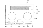
- FIG. 10 is a plan view showing an induction heating cooker according to Embodiment 2. As shown in FIG. 10, the first top plate 3 has an opening 31 formed therein. The second top plate 4 is arranged in an opening 31 formed in the first top plate 3. The first top plate 3 and the second top plate 4 are joined in the same plane.
- the opening 31 of the first top plate 3 is formed, for example, above the cooling device 13 and has a rectangular shape corresponding to the outer diameter of the cooling device 13.
- the display of the cooling port 5 may be omitted.
- the second top plate 4 is disposed in the opening 31 formed in the first top plate 3. Even in such a configuration, the same effect as in the first embodiment can be obtained. Further, since the first top plate 3 and the second top plate 4 are made of different materials, generally the colors are also different. For this reason, even if the display of the cooling port 5 is omitted, the user can recognize the cooling range of the cooling device 13 by the color of the second top plate 4.
- FIG. 11 is a plan view showing a first modification of the induction heating cooker according to the second embodiment. As shown in FIG. 11, a notch 32 may be formed in the first top plate 3. The second top plate 4 is arranged in a notch 32 formed in the first top plate 3. The first top plate 3 and the second top plate 4 are joined in the same plane. Even in such a configuration, the same effect as that of the first modification can be obtained.
- the shape of the opening 31 and the notch 32 is not limited to a rectangle, but may be any shape such as a circle, a square, or an ellipse.
- FIG. 12 is a plan view showing a second modification of the induction heating cooker according to the second embodiment.
- two openings 33a and 33b may be formed in the first top plate 3.
- the openings 33a and 33b are, for example, elliptical.
- the second top plate 4a is arranged in an opening 33a formed in the first top plate 3, and the second top plate 4b is arranged in an opening 33b formed in the first top plate 3.
- the cooling devices 13 are arranged below the openings 33a and 33b, respectively. Even in such a configuration, the same effect as that of the first modification can be obtained.
- the shape of the opening 33a and the opening 33b is not limited to an elliptical shape, but may be any shape such as a circle, a square, or a rectangle.
- the number of openings is not limited to two, but may be any number.
- the operation unit 40c may be configured to select one of the opening 33a and the opening 33b and operate the operation of the cooling device 13 disposed below each of the opening 33a and the opening 33b.
- Embodiment 3 FIG.
- the configuration of the induction heating cooker 100 according to the third embodiment will be described focusing on differences from the first and second embodiments.
- the same components as those in the first and second embodiments are denoted by the same reference numerals, and description thereof is omitted.
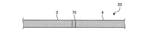
- FIG. 13 is a longitudinal sectional view showing a top plate of the induction heating cooker according to the third embodiment.
- a heat insulating part 70 is arranged between the first top plate 3 and the second top plate 4.
- the heat insulating portion 70 is made of a material having a lower thermal conductivity than the first top plate 3.
- the heat insulating portion 70 is made of, for example, an epoxy resin.
- the thermal conductivity of the epoxy resin is 0.15 to 0.21 [W / mK].
- the top plate 20 according to the third embodiment has a configuration in which the heat insulating portion 70 is provided at the joint between the first top plate 3 and the second top plate 4 according to the first embodiment. Further, the top plate 20 according to the third embodiment has a configuration in which a heat insulating portion 70 is provided at a joint between the opening 31 of the first top plate 3 and the second top plate 4 according to the second embodiment.
- the heat insulating portion 70 that is disposed between the first top plate 3 and the second top plate 4 and that has a lower thermal conductivity than the first top plate 3 is provided. . Therefore, heat transfer between the first top plate 3 and the second top plate 4 can be suppressed. That is, when the heating cooking and the cooling cooking are performed in parallel or continuously, it is possible to prevent the first top plate 3 and the second top plate 4 from thermally interfering with each other. Therefore, it is possible to suppress a rise in the temperature of the second top plate 4 due to the cooking and a decrease in the temperature of the first top plate 3 due to the cooling. Therefore, efficient heating cooking and cooling cooking can be performed.
- Embodiment 4 FIG.
- the configuration of induction heating cooker 100 according to Embodiment 4 will be described focusing on differences from Embodiments 1 to 3 above.
- the same components as those in the first to third embodiments are denoted by the same reference numerals, and description thereof is omitted.
- FIG. 14 is a longitudinal sectional view showing a top plate of the induction heating cooker according to Embodiment 4.
- a convex portion 71 a whose center of the side surface protrudes.
- a concave portion 71b that fits with the convex portion 71a of the first top plate 3 is formed.
- the top plate 20 in the fourth embodiment has a configuration in which the first top plate 3 and the second top plate 4 in the first embodiment are joined in a watertight manner.
- the top plate 20 according to the fourth embodiment has a structure in which the opening 31 of the first top plate 3 and the second top plate 4 according to the second embodiment are joined in a watertight manner.
- a heat insulating portion 70 may be provided on the joint surface between the first top plate 3 and the second top plate 4.
- the first top plate 3 and the second top plate 4 are joined in a watertight manner. For this reason, the invasion of moisture into the induction heating cooker 100 is suppressed from the gap at the joint between the first top plate 3 and the second top plate 4. For example, even if the broth or the like in the cooking vessel 6 spills during the heating cooking, moisture such as the broth can hardly enter the induction heating cooker 100. Therefore, it is possible to prevent malfunction and deterioration of the device due to intrusion of moisture into the induction heating cooker 100.
- the present invention is not limited to this. Any configuration can be adopted as long as the first top plate 3 and the second top plate 4 are joined in a watertight manner.
- a configuration may be employed in which the first top plate 3 and the second top plate 4 are closely bonded to each other with a sealing material.
- the heat insulating portion 70 of the third embodiment and the water-tight joining structure may be used.
- FIG. 15 is a longitudinal sectional view showing a modification of the top plate of the induction heating cooker according to Embodiment 4.
- a convex portion 72 a is formed at an end of the first top plate 3, and the lower portion of the side surface protrudes.
- a concave portion 72b that is concave downward is formed in the convex portion 72a.
- the end of the second top plate 4 is formed with a convex portion 73a that protrudes upward from the side surface.
- the convex portion 73a has a convex portion 73b projecting downward.
- the protrusions 72a of the first top plate 3 and the protrusions 73a of the second top plate 4 are arranged so as to overlap in the up-down direction, and the protrusions 73b and the recesses 72b are fitted to each other.
- the second top plate 4 is joined in a watertight manner.
- the waterproof between the first top plate 3 and the second top plate 4 is provided. Performance can be improved.
- Embodiment 5 FIG.
- the configuration of induction heating cooker 100 according to the fifth embodiment will be described, focusing on differences from the first embodiment.
- the same components as those in the first embodiment are denoted by the same reference numerals, and description thereof is omitted.
- FIG. 16 is an exploded perspective view showing an induction heating cooker according to Embodiment 5.
- FIG. 17 is a longitudinal sectional view showing a top plate of the induction heating cooker according to Embodiment 5.
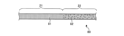
- an induction heating cooker 100 according to the fifth embodiment has a top plate 80 provided at an upper portion.
- the top plate 80 is formed in a flat plate shape, and the cooking container 6 such as a pot is placed thereon.
- the first region 21 of the top plate 80 is made of a first material 81.
- the second region 22 of the top plate 80 is configured by mixing a second material 82 having a higher thermal conductivity than the first material 81 with the first material 81.
- the first material 81 is made of, for example, heat-resistant tempered glass or crystallized glass.
- the second material 82 is made of, for example, aluminum, copper, aluminum nitride, silicon, stainless steel, alumina, or the like.
- the second material 82 is, for example, formed in a particle shape. Other configurations are the same as those in the first embodiment.
- the first region 21 is formed of the first material 81
- the second region 22 is formed of the second material 22 having a higher thermal conductivity than the first material 81.
- the material 82 is configured by being mixed with the first material 81. For this reason, the cooling rate of the cooking container 6 by the cooling device 13 can be improved as compared with the case where the first material 81 is not mixed in the second region 22 of the top plate 80. Therefore, the cooking time in cooling cooking of the cooking container 6 can be shortened.
- the time required for the food in the cooking container 6 to be reduced to the temperature at which the food in the cooking container 6 is stored in the refrigerator after the heating can be shortened, so that the proliferation of bacteria in the food can be suppressed as compared with natural cooling. it can.
- the top plate 80 is formed in a flat plate shape. For this reason, after heating and cooking the cooking container 6 placed on the first region 21 of the top plate 20, the cooking container 6 is slid without lifting up from the first region 21 of the top plate 80 to the second region 22. The cooking container 6 can be easily moved. Therefore, cooperation between heating cooking and cooling cooking becomes easy.
- Embodiment 6 FIG. Hereinafter, the configuration of induction heating cooker 100 according to Embodiment 6 will be described focusing on differences from Embodiments 1 to 5.
- the same components as those in the first to fifth embodiments are denoted by the same reference numerals, and description thereof is omitted.
- FIG. 18 is a longitudinal sectional view schematically showing the internal configuration of the induction heating cooker according to Embodiment 6.
- the induction heating cooker 100 according to Embodiment 6 includes a drain pan 90 and a discharge unit 93.
- Other configurations are the same as those in the first embodiment.
- illustration of a part of the configuration is omitted.
- the drain pan 90 is disposed below the cooling device 13 and receives condensed water generated on the lower surface of the second top plate 4.
- the discharging means 93 discharges the condensed water stored in the drain pan 90.
- the discharging means 93 includes a water distribution pipe 91 connected to the bottom of the drain pan 90, and a drainage vessel 92 for storing condensed water discharged from the water distribution pipe 91.
- the drainage container 92 has an upper portion detachably locked to the second top plate 4 by a locking piece 92a.
- an opening / closing lid 94 is formed above the drainage container 92.
- a procedure for storing condensed water and discarding the condensed water will be described.
- condensed water in which water in the air is condensed (condensed) is generated around the cooling device 13 of the second top plate 4.
- the condensed water attached to the lower surface of the second top plate 4 is dropped downward and stored by the drain pan 90.
- the condensed water stored in the drain pan 90 is stored in a drainage container 92 via a water pipe 91.
- the drain pan 90 disposed below the cooling device 13 and receiving the condensed water generated on the lower surface of the top plate 20, and the discharging means for discharging the condensed water stored in the drain pan 90 93. For this reason, it is possible to prevent the condensed water generated around the cooling device 13 due to the cooling cooking from adhering to electric components, structures, and the like in the induction heating cooker 100. Therefore, an electric short circuit of the electric component in the induction heating cooker 100 can be suppressed. Further, it is possible to prevent deterioration or corrosion of electric components, structures, and the like in the induction heating cooker 100 due to adhesion of moisture.
- Embodiment 7 FIG.
- the cooling device may be configured to cool the cooking container 6 placed in the second area 22.
- a configuration in which an evaporator included in a refrigerant circuit is applied to the cooling device will be described.
- FIG. 19 is a diagram showing a cooling device and a refrigerant circuit of an induction heating cooker according to Embodiment 7.
- the refrigerant circuit 200 includes a compressor 201, a condenser 202, an expansion valve 203, and a cooling device 204 that is an evaporator.
- the compressor 201, the condenser 202, the expansion valve 203, and the cooling device 204 are sequentially connected in a ring by a refrigerant pipe.
- the compressor 201 sucks low-temperature and low-pressure refrigerant and discharges high-temperature and high-pressure refrigerant.
- the high-temperature and high-pressure refrigerant discharged from the compressor 201 flows into the condenser 202 and dissipates heat.
- the temperature of the refrigerant is reduced, the refrigerant becomes a liquid state refrigerant, and flows out of the condenser 202.
- the refrigerant flowing out of the condenser 202 is decompressed by the expansion valve 203 to become a gas-liquid two-phase refrigerant, and flows into the cooling device 204 as an evaporator.
- the refrigerant that has flowed into the cooling device 204 evaporates by absorbing the heat from the cooking container 6, becomes a gaseous refrigerant, and flows out of the cooling device 204.
- the refrigerant flowing out of the cooling device 204 is sucked into the compressor 201.
- the cooking container 6 placed on the top plate 20 can be cooled, and the same effects as those of the first to sixth embodiments can be obtained.
Landscapes
- Physics & Mathematics (AREA)
- Electromagnetism (AREA)
- Induction Heating Cooking Devices (AREA)
- Electric Stoves And Ranges (AREA)
Abstract
本発明に係る誘導加熱調理器は、平板状に形成され、第1領域と第1領域よりも熱伝導率が高い第2領域とを含むトッププレートと、トッププレートの第1領域の下方に配置され、第1領域に載置された調理容器を誘導加熱する加熱コイルと、トッププレートの第2領域の下方に配置され、第2領域に載置された調理容器を冷却する冷却装置と、を備えたものである。
Description
本発明は、調理容器が載置されるトッププレートを備えた誘導加熱調理器に関する。
従来の技術においては、例えば、調理用器具を積載する積載部と、積載部の下方に設けられ、積載部に積載された調理用器具を電磁誘導作用によって加熱する加熱装置と、を備えた電磁調理器が提案されている(特許文献1参照)。この電磁調理器は、調理用器具が積載される方向と反対の方向から積載部に当接され、積載部に積載された調理用器具を冷却する冷却装置を備える。積載部は、例えば、結晶化ガラスで構成されている。
特許文献1に記載の電磁調理器は、積載部の下面に当接した冷却装置によって、調理用器具から積載部へ伝熱した熱を吸熱することで調理用器具を冷却する。このため、電磁誘導作用による調理容器の加熱と比較して、冷却装置による調理容器の冷却に時間がかかる、という問題点があった。
本発明は、上記のような課題を解決するためになされたもので、トッププレートに載置された調理容器の冷却速度を向上することができる誘導加熱調理器を得るものである。
本発明に係る誘導加熱調理器は、平板状に形成され、第1領域と前記第1領域よりも熱伝導率が高い第2領域とを含むトッププレートと、前記トッププレートの前記第1領域の下方に配置され、前記第1領域に載置された調理容器を誘導加熱する加熱コイルと、前記トッププレートの前記第2領域の下方に配置され、前記第2領域に載置された調理容器を冷却する冷却装置と、を備えたものである。
本発明は、トッププレートの第1領域に載置された調理容器を誘導加熱する加熱コイルと、トッププレートの第2領域に載置された調理容器を冷却する冷却装置とを備える。トッププレートの第2領域は第1領域よりも熱伝導率が高い。このため、冷却装置の上方のトッププレートの熱伝導率が第1領域の熱伝導率である場合と比較して、冷却装置による調理容器の冷却速度を向上することができる。
実施の形態1.
(構成)
図1は、実施の形態1に係る誘導加熱調理器を示す平面図である。
図2は、実施の形態1に係る誘導加熱調理器を示す分解斜視図である。
図1及び図2に示すように、誘導加熱調理器100の上部には、平板状に形成され、鍋等の調理容器6が載置されるトッププレート20を有している。トッププレート20は、第1トッププレート3と、第2トッププレート4とを有する。第1トッププレート3は、第2トッププレート4と隣接して配置されている。第1トッププレート3は、トッププレート20の手前側に配置されている。第2トッププレート4は、トッププレート20の奥側に配置されている。第1トッププレート3と第2トッププレート4とは、同一平面状に接合されている。
(構成)
図1は、実施の形態1に係る誘導加熱調理器を示す平面図である。
図2は、実施の形態1に係る誘導加熱調理器を示す分解斜視図である。
図1及び図2に示すように、誘導加熱調理器100の上部には、平板状に形成され、鍋等の調理容器6が載置されるトッププレート20を有している。トッププレート20は、第1トッププレート3と、第2トッププレート4とを有する。第1トッププレート3は、第2トッププレート4と隣接して配置されている。第1トッププレート3は、トッププレート20の手前側に配置されている。第2トッププレート4は、トッププレート20の奥側に配置されている。第1トッププレート3と第2トッププレート4とは、同一平面状に接合されている。
第1トッププレート3は、後述する加熱コイル11からの高周波磁界を妨げず、調理容器6に渦電流を流して誘導加熱することができる材料により構成されている。例えば、第1トッププレート3は、耐熱強化ガラス又は結晶化ガラス等で構成されている。
第2トッププレート4は、第1トッププレート3よりも熱伝導率が高い材料により構成されている。例えば、第2トッププレート4は、アルミニウム、銅、窒化アルミニウム、シリコン、ステンレス、又はアルミナ等で構成されている。例えば、結晶化ガラスの熱伝導率は、1[W/mK]である。アルミニウムの熱伝導率は、236[W/mK]である。銅の熱伝導率は、398[W/mK]である。窒化アルミニウムの熱伝導率は、285[W/mK]である。シリコンの熱伝導率は、168[W/mK]である。ステンレスの熱伝導率は、16.7~20.9[W/mK]である。アルミナの熱伝導率は、30[W/mK]である。即ち、第2トッププレート4は、第1トッププレート3と比較して、例えば、およそ16倍から400倍高い熱伝導性を有する。
第1トッププレート3の下方には、第1トッププレート3に載置された調理容器6を誘導加熱する加熱コイル11及び加熱コイル12が設けられている。加熱コイル11及び加熱コイル12は、誘導加熱調理器100の手前側において、横方向に並設されている。第1トッププレート3には、加熱コイル11及び加熱コイル12のそれぞれ加熱範囲に対応して、調理容器6の大まかな載置位置を示す第1加熱口1及び第2加熱口2が形成されている。第1加熱口1及び第2加熱口2は、例えば加熱コイル11及び加熱コイル12の外径形状に対応した円形の表示である。第1加熱口1及び第2加熱口2は、第1トッププレート3への塗料の塗布又は印刷等により形成されている。
加熱コイル11及び加熱コイル12は、絶縁皮膜された金属からなる導線が巻き付けられることにより構成される。導線としては、例えば、銅又はアルミニウムなど任意の金属を用いることができる。加熱コイル11及び加熱コイル12に高周波電流が供給されることで、各加熱コイルから高周波磁界が発生する。これにより、加熱コイル11及び加熱コイル12の直上の第1トッププレート3上に載置された調理容器6が誘導加熱される。
第2トッププレート4の下方には、第2トッププレート4に載置された調理容器6を冷却する冷却装置13が設けられている。冷却装置13は、誘導加熱調理器100の奥側において、第2トッププレート4の横方向のほぼ中央位置に設けられている。第2トッププレート4には、冷却装置13の冷却範囲に対応して、調理容器6の大まかな載置位置を示す冷却口5が形成されている。冷却口5は、例えば、冷却装置13の上方に形成され、冷却装置13の外径形状に対応した長方形の表示である。冷却口5は、第2トッププレート4への塗料の塗布又は印刷等により形成されている。
なお、冷却口5の形状は、長方形に限定されない。冷却口5は、第2トッププレート4に載置された調理容器6が、冷却装置13によって冷却可能となる大まかな範囲を示すものであれば良い。例えば、冷却口5の形状は、円形、楕円形、又は正方形であっても良い。また、1つの冷却装置13に対して複数の冷却口5を設けても良い。また、冷却装置13を複数設け、それぞれの冷却範囲に対応して複数の冷却口5を設けても良い。また、複数の冷却装置13に対して、1つの冷却口5を設けても良い。
冷却装置13は、例えばペルチェ素子を含んで構成される。冷却装置13は、第2トッププレート4を下面側から冷却することで、第2トッププレート4に載置された調理容器6を冷却する。冷却装置13の詳細は後述する。
図3は、実施の形態1に係る誘導加熱調理器の第1領域及び第2領域を説明する平面図である。
図3に示すように、トッププレート20は、第1領域21と第2領域22とを含む。第2領域22は、第1領域21よりも熱伝導率が高い領域である。即ち、第1トッププレート3よりも熱伝導率が高い材料である第2トッププレート4は、トッププレート20における第2領域22を構成する。また、第1トッププレート3は、トッププレート20における第1領域21を構成する。加熱コイル11及び加熱コイル12は、トッププレート20の第1領域21に載置された調理容器6を誘導加熱する。冷却装置13は、トッププレート20の第2領域22に載置された調理容器6を冷却する。
図3に示すように、トッププレート20は、第1領域21と第2領域22とを含む。第2領域22は、第1領域21よりも熱伝導率が高い領域である。即ち、第1トッププレート3よりも熱伝導率が高い材料である第2トッププレート4は、トッププレート20における第2領域22を構成する。また、第1トッププレート3は、トッププレート20における第1領域21を構成する。加熱コイル11及び加熱コイル12は、トッププレート20の第1領域21に載置された調理容器6を誘導加熱する。冷却装置13は、トッププレート20の第2領域22に載置された調理容器6を冷却する。
再び、図1及び図2を参照する。
トッププレート20の手前側には、加熱コイル11及び加熱コイル12で調理容器6等を加熱する際の投入電力及び調理メニュー等を設定するための入力装置として、操作部40a及び操作部40bが設けられている。また、操作部40a及び操作部40bの近傍には、報知手段として、各加熱コイルの動作状態および操作部40a及び操作部40bからの入力操作の内容等を表示する表示部41a及び表示部41bが設けられている。
トッププレート20の手前側には、加熱コイル11及び加熱コイル12で調理容器6等を加熱する際の投入電力及び調理メニュー等を設定するための入力装置として、操作部40a及び操作部40bが設けられている。また、操作部40a及び操作部40bの近傍には、報知手段として、各加熱コイルの動作状態および操作部40a及び操作部40bからの入力操作の内容等を表示する表示部41a及び表示部41bが設けられている。
また、トッププレート20の手前側の中央には、冷却装置13で調理容器6等を冷却する際の投入電力及び調理メニュー等を設定するための入力装置として、操作部40cが設けられている。また、操作部40cの近傍には、報知手段として、冷却装置13の動作状態および操作部40cからの入力操作の内容等を表示する表示部41cが設けられている。
操作部40a~40cは、例えばプッシュスイッチ及びタクトスイッチ等の機械的なスイッチ、電極の静電容量の変化により入力操作を検知するタッチスイッチ等により構成されている。また、表示部41a~41cは、例えばLCD及びLED等で構成されている。なお、操作部40aと表示部41aとを一体に構成した操作表示部としても良い。また、操作部40bと表示部41bとを一体に構成した操作表示部としても良い。また、操作部40cと表示部41cとを一体に構成した操作表示部としても良い。操作表示部は、例えば、LCDの上面にタッチスイッチを配置したタッチパネル等によって構成される。なお、LCDは、Liquid Crystal Deviceの略称である。また、LEDは、Light Emitting Diodeの略称である。
なお、操作部40a~40c及び表示部41a~41cの数は、上述のように加熱コイル11及び加熱コイル12、並びに冷却装置13のそれぞれに対して1つずつ設けられる構成に限定されない。例えば、加熱コイル11、加熱コイル12及び冷却装置13の共通のものとして、1つの操作部40及び表示部41を設けても良い。
誘導加熱調理器100の内部には、加熱コイル11、加熱コイル12及び冷却装置13を駆動する駆動回路46と、駆動回路46を含め誘導加熱調理器100全体の動作を制御するための制御装置45とが設けられている。
制御装置45は、専用のハードウェア、又はメモリに格納されるプログラムを実行するCPUで構成される。なお、CPUは、Central Processing Unitの略称である。また、CPUは、中央処理装置、処理装置、演算装置、マイクロプロセッサ、マイクロコンピュータ、又はプロセッサともいう。
制御装置45が専用のハードウェアである場合、制御装置45は、例えば、単一回路、複合回路、ASIC、FPGA、又はこれらを組み合わせたものが該当する。制御装置45が実現する各機能部のそれぞれを、個別のハードウェアで実現しても良いし、各機能部を一つのハードウェアで実現しても良い。なお、ASICは、Application Specific Integrated Circuitの略称である。また、FPGAは、Field-Programmable Gate Arrayの略称である。
制御装置45がCPUの場合、制御装置45が実行する各機能は、ソフトウェア、ファームウェア、又はソフトウェアとファームウェアとの組み合わせにより実現される。ソフトウェア及びファームウェアは、プログラムとして記述され、メモリに格納される。CPUは、メモリに格納されたプログラムを読み出して実行することにより、制御装置45の各機能を実現する。ここで、メモリは、例えば、RAM、ROM、フラッシュメモリ、EPROM、EEPROM等の、不揮発性又は揮発性の半導体メモリである。
なお、制御装置45の機能の一部を専用のハードウェアで実現し、一部をソフトウェア又はファームウェアで実現するようにしても良い。なお、RAMは、Random Access Memoryの略称である。また、ROMは、Read Only Memoryの略称である。また、EPROMは、Erasable Programmable Read Only Memoryの略称である。また、EEPROMは、Electrically Erasable Programmable Read-Only Memoryの略称である。
第2トッププレート4の下面には、温度センサ42(図1に破線表示)が設けられている。温度センサ42は、例えばサーミスタにより構成される。温度センサ42は、例えば、冷却装置13の近傍に配置される。温度センサ42は、調理容器6から第2トッププレート4に伝熱した熱により温度を検知する。制御装置45は、温度センサ42の検知した温度に応じて冷却装置13を制御する。
誘導加熱調理器100の内部には、送風機60が設けられている。送風機60は、誘導加熱調理器100本体の外部の空気を吸気口(図示省略)から本体内に吸気し、本体内部に冷却風を供給する。本体内に供給された冷却風は、本体内部の各部品及び冷却装置13を冷却した後、排気口(図示省略)から本体の外部に排気される。
図4は、実施の形態1に係る誘導加熱調理器の構成を示すブロック図である。
図4に示すように、加熱コイル11は、駆動回路46aにより駆動制御される。加熱コイル12は、駆動回路46bにより駆動制御される。冷却装置13は、駆動回路46cにより駆動制御される。駆動回路46a及び駆動回路46bは、インバータ回路を含む。駆動回路46a及び駆動回路46bは、それぞれ、交流電源から供給された交流電力を20kHz~100kHz程度の高周波の交流電力に変換して、加熱コイル11及び加熱コイル12へ出力する。駆動回路46cは、直流電源回路を含む。駆動回路46cは、交流電源から供給された交流電力を、任意の直流電力に変換して、冷却装置13へ出力する。制御装置45は、操作部40a~40c及び温度センサ42からの入力に応じて、駆動回路46a~46c及び送風機60の動作を制御する。
図4に示すように、加熱コイル11は、駆動回路46aにより駆動制御される。加熱コイル12は、駆動回路46bにより駆動制御される。冷却装置13は、駆動回路46cにより駆動制御される。駆動回路46a及び駆動回路46bは、インバータ回路を含む。駆動回路46a及び駆動回路46bは、それぞれ、交流電源から供給された交流電力を20kHz~100kHz程度の高周波の交流電力に変換して、加熱コイル11及び加熱コイル12へ出力する。駆動回路46cは、直流電源回路を含む。駆動回路46cは、交流電源から供給された交流電力を、任意の直流電力に変換して、冷却装置13へ出力する。制御装置45は、操作部40a~40c及び温度センサ42からの入力に応じて、駆動回路46a~46c及び送風機60の動作を制御する。
図5は、実施の形態1に係る誘導加熱調理器の冷却装置を示す平面図である。
図6は、実施の形態1に係る誘導加熱調理器の冷却装置の構成を模式的に示す側面図である。
図5及び図6に示すように、冷却装置13は、複数のP型熱電半導体13a、複数のN型熱電半導体13b、複数の電極13c、及び一対の絶縁部材13dを備える。一対の絶縁部材13dは、例えばセラミックなどの絶縁性の材料により構成される。一対の絶縁部材13dは、平板状に構成されている。一対の絶縁部材13dは、対向して配置されている。
図6は、実施の形態1に係る誘導加熱調理器の冷却装置の構成を模式的に示す側面図である。
図5及び図6に示すように、冷却装置13は、複数のP型熱電半導体13a、複数のN型熱電半導体13b、複数の電極13c、及び一対の絶縁部材13dを備える。一対の絶縁部材13dは、例えばセラミックなどの絶縁性の材料により構成される。一対の絶縁部材13dは、平板状に構成されている。一対の絶縁部材13dは、対向して配置されている。
複数のP型熱電半導体13a及び複数のN型熱電半導体13bは、一対の絶縁部材13dの間に配置されている。P型熱電半導体13aとN型熱電半導体13bとは、交互に配置されている。電極13cは、隣り合って配置されたP型熱電半導体13aとN型熱電半導体13bを電気的に接続する。電極13cの端部にはリード線13eが接続されている。リード線13eの他方は駆動回路46cに接続され、駆動回路46cからの直流電圧が印加される。
P型熱電半導体13a、N型熱電半導体13b及び電極13cはペルチェ素子を構成する。電極13cに直流電流が流れると、P型熱電半導体13a及びN型熱電半導体13bと電極13cとの接触面で発熱又は吸熱が起きる。これにより、一対の絶縁部材13dのうち、コールドサイドとなる一方は冷却され、一対の絶縁部材13dのうち、ホットサイドとなる他方は加熱される。
図7は、実施の形態1に係る誘導加熱調理器の冷却装置の設置状態を模式的に示す側面図である。
図7に示すように、冷却装置13は、コールドサイドとなる絶縁部材13dが第2トッププレート4と対向するように、第2トッププレート4の下面に密着して配置されている。一対の絶縁部材13dのうち、ホットサイドとなる他方には、放熱手段61が密着して配置されている。放熱手段61は、例えば放熱フィンによって構成される。放熱手段61は、送風機60からの冷却風が供給され、ホットサイドとなる絶縁部材13dからの熱が放熱される。
図7に示すように、冷却装置13は、コールドサイドとなる絶縁部材13dが第2トッププレート4と対向するように、第2トッププレート4の下面に密着して配置されている。一対の絶縁部材13dのうち、ホットサイドとなる他方には、放熱手段61が密着して配置されている。放熱手段61は、例えば放熱フィンによって構成される。放熱手段61は、送風機60からの冷却風が供給され、ホットサイドとなる絶縁部材13dからの熱が放熱される。
なお、放熱手段61の側方又は下方に、放熱手段61へ冷却風を送風する送風機を更に設けても良い。なお、冷却装置13と第2トッププレート4との接合面および冷却装置13と放熱手段61との接合面には、サーマルグリース又は接着材等を塗布し、空気が介在しないように密着させるのが望ましい。
(動作)
次に、本実施の形態1における誘導加熱調理器の動作について、調理容器6を誘導加熱する加熱調理と、調理容器6を冷却する冷却調理とに分けて説明する。
次に、本実施の形態1における誘導加熱調理器の動作について、調理容器6を誘導加熱する加熱調理と、調理容器6を冷却する冷却調理とに分けて説明する。
[加熱調理]
使用者は、鍋などの調理容器6を第1トッププレート3の第1加熱口1又は第2加熱口2に載置する。以下、調理容器6を第1加熱口1に載置した場合を説明する。
使用者は、操作部40aにより加熱開始の入力操作を行う。制御装置45は、操作部40aからの入力操作によって設定された電力に応じて、駆動回路46aの動作を制御する。例えば、制御装置45は、設定された電力に応じて、駆動回路46aから加熱コイル11へ供給される高周波電流の周波数を可変させる。
使用者は、鍋などの調理容器6を第1トッププレート3の第1加熱口1又は第2加熱口2に載置する。以下、調理容器6を第1加熱口1に載置した場合を説明する。
使用者は、操作部40aにより加熱開始の入力操作を行う。制御装置45は、操作部40aからの入力操作によって設定された電力に応じて、駆動回路46aの動作を制御する。例えば、制御装置45は、設定された電力に応じて、駆動回路46aから加熱コイル11へ供給される高周波電流の周波数を可変させる。
加熱コイル11に高周波電流が流れると高周波磁界が発生し、第1加熱口1に載置された調理容器6の底には磁束変化を打ち消す方向に渦電流が流れ、その流れる渦電流の損失よって調理容器6が加熱される。
[冷却調理]
使用者は、鍋などの調理容器6を第2トッププレート4の冷却口5に載置する。次に、使用者は、操作部40cにより冷却開始の入力操作を行う。制御装置45は、操作部40cからの入力操作によって設定された電力に応じて、駆動回路46cの動作を制御する。ここで、操作部40cからの入力操作としては、例えば「弱」「中」「強」の3段階の冷却温度レベルの入力操作、又は調理容器6の設定温度の値の入力操作などがある。
使用者は、鍋などの調理容器6を第2トッププレート4の冷却口5に載置する。次に、使用者は、操作部40cにより冷却開始の入力操作を行う。制御装置45は、操作部40cからの入力操作によって設定された電力に応じて、駆動回路46cの動作を制御する。ここで、操作部40cからの入力操作としては、例えば「弱」「中」「強」の3段階の冷却温度レベルの入力操作、又は調理容器6の設定温度の値の入力操作などがある。
制御装置45は、操作部40cからの入力操作に応じて、駆動回路46cの動作を制御する。例えば、制御装置45は、冷却温度レベルに応じて、冷却装置13へ供給する直流電力のオンオフを制御する。具体的には、入力操作が「強」である場合、制御装置45は、駆動回路46cから冷却装置13への直流電力の供給を常時オン状態にする。入力操作が「中」である場合、制御装置45は、駆動回路46cから冷却装置13への直流電力の供給を周期的にオン状態とオフ状態とを切り替える。入力操作が「弱」である場合、制御装置45は、駆動回路46cから冷却装置13への直流電力の供給を、入力操作が「中」と比較してオフ状態が長くなるように、周期的にオン状態とオフ状態とを切り替える。
また例えば、制御装置45は、温度センサ42の検知した温度が、設定温度となるように冷却装置13を制御する。具体的には、制御装置45は、温度センサ42の検知した温度が、設定温度よりも低い場合、駆動回路46cから冷却装置13への直流電力の供給をオン状態にする。また、制御装置45は、温度センサ42の検知した温度が、設定温度以上である場合、駆動回路46cから冷却装置13への直流電力の供給をオフ状態にする。なお、制御装置45による冷却装置13の制御は、上述した制御に限定されず、任意の温度制御を適用することができる。例えば、制御装置45は、設定温度と温度センサ42が検知した温度との温度差が大きいほど、駆動回路46cのオンデューティ比を増加させる制御を行ってもよい。
冷却装置13に直流電力が供給されると、コールドサイドとなる絶縁部材13dが密着する第2トッププレート4が冷却され、第2トッププレート4に載置された調理容器6が冷却される。
なお、上述した加熱調理と冷却調理とは、それぞれ並行して動作を行うこともでき、それぞれ連続して行うこともできる。例えば、使用者は、第1加熱口1と冷却口5とのそれぞれ2つの調理容器6を載置し、加熱コイル11による加熱調理と冷却装置13による冷却調理とを並行して動作させても良い。また例えば、使用者は、1つの調理容器6を第1加熱口1に載置して、加熱コイル11による加熱調理を行わせた後、第1加熱口1に載置した調理容器6を冷却口5へと移動させ、冷却装置13による冷却調理を行わせてもよい。
(効果)
以上のように本実施の形態1においては、トッププレート20の第1領域21の下方に配置された加熱コイル11と、トッププレート20の第2領域22の下方に配置された冷却装置13とを備える。トッププレート20は、第2領域22が、第1領域21よりも熱伝導率が高く構成されている。このため、トッププレート20の第2領域22の熱伝導率が第1領域21の熱伝導率である場合と比較して、冷却装置13による調理容器6の冷却速度を向上することができる。よって、調理容器6の冷却調理における調理時間を短縮することができる。また、加熱調理の後、調理容器6内の調理物を冷蔵庫へ保存する温度まで低下する時間を短縮することができるため、自然冷却と比較して、調理物における菌の繁殖を抑制することができる。
以上のように本実施の形態1においては、トッププレート20の第1領域21の下方に配置された加熱コイル11と、トッププレート20の第2領域22の下方に配置された冷却装置13とを備える。トッププレート20は、第2領域22が、第1領域21よりも熱伝導率が高く構成されている。このため、トッププレート20の第2領域22の熱伝導率が第1領域21の熱伝導率である場合と比較して、冷却装置13による調理容器6の冷却速度を向上することができる。よって、調理容器6の冷却調理における調理時間を短縮することができる。また、加熱調理の後、調理容器6内の調理物を冷蔵庫へ保存する温度まで低下する時間を短縮することができるため、自然冷却と比較して、調理物における菌の繁殖を抑制することができる。
また、加熱調理と冷却調理とを並行して又は連続して行うことができるため、調理容器6内の調理物に対して冷却と加熱の連携調理が可能となる。また、加熱調理の後、冷却調理を行うことで、調理容器6内の調理物への味の浸み込みを良くして、調理物のおいしさを増すことができる。
また、トッププレート20は、平板状に形成されている。このため、トッププレート20の第1領域21に載置した調理容器6を加熱調理した後に、調理容器6を持ち上げることなく、スライドさせて、トッププレート20の第1領域21から第2領域22へ調理容器6を容易に移動させることができる。よって、加熱調理と冷却調理との連携が容易となる。
また、本実施の形態1においては、トッププレート20は、第1領域21を構成する第1トッププレート3と、第2領域22を構成し、第1トッププレート3よりも熱伝導率が高い材料である第2トッププレート4と、を有する。このため、第2トッププレート4の熱伝導率が第1トッププレート3の熱伝導率である場合と比較して、第2トッププレート4に載置された調理容器6の冷却速度を向上することができる。よって、調理容器6の冷却調理における調理時間を短縮することができる。
また、第1トッププレート3と第2トッププレート4とは、同一平面状に接合されている。このため、第1トッププレート3に載置した調理容器6を加熱調理した後に、調理容器6を持ち上げることなく、スライドさせて、第1トッププレート3から第2トッププレート4へ調理容器6を容易に移動させることができる。よって、加熱調理と冷却調理との連携が容易となる。
また、第1トッププレート3は、例えば、耐熱強化ガラス又は結晶化ガラス等で構成されている。第2トッププレート4は、例えば、アルミニウム、銅、窒化アルミニウム、シリコン、ステンレス、又はアルミナ等で構成されている。一般に、耐熱強化ガラス又は結晶化ガラスは、アルミニウム、銅、窒化アルミニウム、シリコン、ステンレス、又はアルミナと比較して高価である。このため、トッププレート20の全体が、耐熱強化ガラス又は結晶化ガラス等で構成されている場合と比較して、耐熱強化ガラス又は結晶化ガラス等の材料の使用量を少なくすることができ、製造コストの低減を図ることができる。
また、本実施の形態1においては、第2トッププレート4は、第1トッププレート3と隣接して配置されている。このため、第1トッププレート3に載置した調理容器6を加熱調理した後に、調理容器6を第1トッププレート3から第2トッププレート4へ調理容器6を容易に移動させることができる。よって、加熱調理と冷却調理との連携が容易となる。
また、本実施の形態1においては、トッププレート20は、冷却装置13の上方に、調理容器6の載置位置を示す冷却口5が形成されている。このため、使用者は、冷却調理における調理容器6の載置位置を把握し易くなる。よって、調理容器6が冷却装置13による冷却調理が可能となる位置に載置され易くすることができ、調理容器6の効率的な冷却が可能となる。
また、本実施の形態1においては、トッププレート20の第2領域22の下面に配置された温度センサ42と、温度センサ42の検知した温度に応じて、冷却装置13を制御する制御装置45とを備える。このため、トッププレート20の第2領域22の熱伝導率が第1領域21の熱伝導率である場合と比較して、調理容器6の温度検知の温度誤差及び温度変化の時間遅れを低減することができる。よって、冷却調理において調理容器6の温度を速く正確に検出することが可能となり、温度センサ42からの検出信号をもとに精度の良い温度制御を行うことができる。
また、本実施の形態1においては、操作部40からの入力操作に応じて、冷却装置13を制御する制御装置45を備える。このため、冷却調理の開始及び停止等、冷却装置13の動作を容易に設定できる。
また、温度センサ42の検知した温度が、設定温度となるように冷却装置13を制御する制御装置45を備える。このため、冷却調理において温度センサ42からの検出信号をもとに制度の良い温度制御を行うことができる。
(変形例1)
図8は、実施の形態1に係る誘導加熱調理器の変形例1における冷却装置の設置状態を模式的に示す側面図である。
図8に示すように、冷却装置13は、トッププレート20の下面に、弾性体62を介して密着して配置されても良い。即ち、冷却装置13は、コールドサイドとなる絶縁部材13dと、第2トッププレート4との間に、弾性体62が介在している。弾性体62は、第1トッププレート3よりも熱伝導率が高い材料である。弾性体62は、例えば、シリコン等により構成されている。
図8は、実施の形態1に係る誘導加熱調理器の変形例1における冷却装置の設置状態を模式的に示す側面図である。
図8に示すように、冷却装置13は、トッププレート20の下面に、弾性体62を介して密着して配置されても良い。即ち、冷却装置13は、コールドサイドとなる絶縁部材13dと、第2トッププレート4との間に、弾性体62が介在している。弾性体62は、第1トッププレート3よりも熱伝導率が高い材料である。弾性体62は、例えば、シリコン等により構成されている。
このような構成により、冷却装置13と第2トッププレート4との間に空気層が介在しないように、冷却装置13と第2トッププレート4とを密着させることができる。よって、冷却装置13による調理容器6の冷却効率を向上することができ、調理容器6の冷却速度を向上することができる。
(変形例2)
図9は、実施の形態1に係る誘導加熱調理器の変形例2を示す分解斜視図である。
図9に示すように、第1トッププレート3と第2トッププレート4とを左右に配置しても良い。第1トッププレート3は、トッププレート20の左側に配置されている。第2トッププレート4は、トッププレート20の右側に配置されている。第1トッププレート3は、第2トッププレート4と隣接して配置されている。第1トッププレート3と第2トッププレート4とは、同一平面状に接合されている。
図9は、実施の形態1に係る誘導加熱調理器の変形例2を示す分解斜視図である。
図9に示すように、第1トッププレート3と第2トッププレート4とを左右に配置しても良い。第1トッププレート3は、トッププレート20の左側に配置されている。第2トッププレート4は、トッププレート20の右側に配置されている。第1トッププレート3は、第2トッププレート4と隣接して配置されている。第1トッププレート3と第2トッププレート4とは、同一平面状に接合されている。
第1トッププレート3の下方には、加熱コイル11が設けられている。加熱コイル11は、誘導加熱調理器100の手前の左側に配置されている。第1トッププレート3には、加熱コイル11の加熱範囲に対応して、第1加熱口1が形成されている。第2トッププレート4の下方には、冷却装置13が設けられている。冷却装置13は、誘導加熱調理器100の右側に設けられている。第2トッププレート4には、冷却装置13の冷却範囲に対応して、冷却口5が形成されている。なお、第1加熱口1と冷却口5は左右の位置を限定するものではない。
このような構成においても、上記実施の形態1と同様の効果を得ることができる。
このような構成においても、上記実施の形態1と同様の効果を得ることができる。
実施の形態2.
以下、実施の形態2における誘導加熱調理器100の構成について、上記実施の形態1との相違点を中心に説明する。なお、上記実施の形態1と同じ構成には同一の符号を付し説明を省略する。
以下、実施の形態2における誘導加熱調理器100の構成について、上記実施の形態1との相違点を中心に説明する。なお、上記実施の形態1と同じ構成には同一の符号を付し説明を省略する。
図10は、実施の形態2に係る誘導加熱調理器を示す平面図である。
図10に示すように、第1トッププレート3には、開口31が形成されている。第2トッププレート4は、第1トッププレート3に形成された開口31に配置されている。そして、第1トッププレート3と第2トッププレート4とは、同一平面状に接合されている。
図10に示すように、第1トッププレート3には、開口31が形成されている。第2トッププレート4は、第1トッププレート3に形成された開口31に配置されている。そして、第1トッププレート3と第2トッププレート4とは、同一平面状に接合されている。
第1トッププレート3の開口31は、例えば、冷却装置13の上方に形成され、冷却装置13の外径形状に対応した長方形の形状である。なお、本実施の形態2においては、冷却口5の表示を省略しても良い。
以上のように本実施の形態2においては、第2トッププレート4は、第1トッププレート3に形成された開口31に配置されている。このような構成においても、上記実施の形態1と同様の効果を得ることができる。また、第1トッププレート3と第2トッププレート4とは材料が異なるため、一般に色彩も異なる。このため、冷却口5の表示を省略しても、第2トッププレート4の色彩によって冷却装置13の冷却範囲を使用者が認識することができる。
(変形例1)
図11は、実施の形態2に係る誘導加熱調理器の変形例1を示す平面図である。
図11に示すように、第1トッププレート3に、切り欠き32を形成しても良い。第2トッププレート4は、第1トッププレート3に形成された切り欠き32に配置されている。そして、第1トッププレート3と第2トッププレート4とは、同一平面状に接合されている。
このような構成においても、上記変形例1と同様の効果を得ることができる。
図11は、実施の形態2に係る誘導加熱調理器の変形例1を示す平面図である。
図11に示すように、第1トッププレート3に、切り欠き32を形成しても良い。第2トッププレート4は、第1トッププレート3に形成された切り欠き32に配置されている。そして、第1トッププレート3と第2トッププレート4とは、同一平面状に接合されている。
このような構成においても、上記変形例1と同様の効果を得ることができる。
なお、上述した開口31、切り欠き32の形状は、長方形に限らず、円形、正方形、又は楕円形など任意の形状で良い。
(変形例2)
図12は、実施の形態2に係る誘導加熱調理器の変形例2を示す平面図である。
図12に示すように、第1トッププレート3に、2つの開口33a及び開口33bを形成しても良い。開口33a及び開口33bは、例えば楕円形である。第2トッププレート4aは、第1トッププレート3に形成された開口33aに配置され、第2トッププレート4bは、第1トッププレート3に形成された開口33bに配置されている。開口33a及び開口33bの下方には、それぞれ、冷却装置13が配置されている。
このような構成においても、上記変形例1と同様の効果を得ることができる。
図12は、実施の形態2に係る誘導加熱調理器の変形例2を示す平面図である。
図12に示すように、第1トッププレート3に、2つの開口33a及び開口33bを形成しても良い。開口33a及び開口33bは、例えば楕円形である。第2トッププレート4aは、第1トッププレート3に形成された開口33aに配置され、第2トッププレート4bは、第1トッププレート3に形成された開口33bに配置されている。開口33a及び開口33bの下方には、それぞれ、冷却装置13が配置されている。
このような構成においても、上記変形例1と同様の効果を得ることができる。
なお、上述した開口33a及び開口33bの形状は、楕円形に限らず、円形、正方形、又は長方形など任意の形状で良い。また、開口の数は2つに限らず任意の数で良い。なお、操作部40cは、開口33a及び開口33bの何れかを選択し、開口33a及び開口33bのそれぞれの下方に配置された冷却装置13の動作を操作する構成としても良い。
実施の形態3.
以下、実施の形態3における誘導加熱調理器100の構成について、上記実施の形態1及び2との相違点を中心に説明する。なお、上記実施の形態1及び2と同じ構成には同一の符号を付し説明を省略する。
以下、実施の形態3における誘導加熱調理器100の構成について、上記実施の形態1及び2との相違点を中心に説明する。なお、上記実施の形態1及び2と同じ構成には同一の符号を付し説明を省略する。
図13は、実施の形態3に係る誘導加熱調理器のトッププレートを示す縦断面図である。
図13に示すように、第1トッププレート3と第2トッププレート4との間に、断熱部70が配置されている。断熱部70は、第1トッププレート3よりも熱伝導率が低い材料で構成されている。断熱部70は、例えば、エポキシ樹脂等で構成されている。なお、エポキシ樹脂の熱伝導率は、0.15~0.21[W/mK]である。
図13に示すように、第1トッププレート3と第2トッププレート4との間に、断熱部70が配置されている。断熱部70は、第1トッププレート3よりも熱伝導率が低い材料で構成されている。断熱部70は、例えば、エポキシ樹脂等で構成されている。なお、エポキシ樹脂の熱伝導率は、0.15~0.21[W/mK]である。
その他の構成は、上記実施の形態1又は2と同様である。即ち、本実施の形態3におけるトッププレート20は、上記実施の形態1における第1トッププレート3と第2トッププレート4との接合部分に断熱部70を設けた構成である。また、本実施の形態3におけるトッププレート20は、上記実施の形態2における第1トッププレート3の開口31と第2トッププレート4との接合部分に断熱部70を設けた構成である。
以上のように本実施の形態3においては、第1トッププレート3と第2トッププレート4との間に配置され、第1トッププレート3よりも熱伝導率が低い材料である断熱部70を備える。このため、第1トッププレート3と第2トッププレート4との間の伝熱を抑制することができる。即ち、加熱調理と冷却調理とを並行して又は連続して行う場合において、第1トッププレート3と第2トッププレート4との互いの熱的な干渉を防ぐことができる。よって、加熱調理による第2トッププレート4の温度上昇及び冷却調理による第1トッププレート3の温度低下を抑制することができる。したがって、効率的な加熱調理と冷却調理とを行うことができる。
実施の形態4.
以下、実施の形態4における誘導加熱調理器100の構成について、上記実施の形態1~3との相違点を中心に説明する。なお、上記実施の形態1~3と同じ構成には同一の符号を付し説明を省略する。
以下、実施の形態4における誘導加熱調理器100の構成について、上記実施の形態1~3との相違点を中心に説明する。なお、上記実施の形態1~3と同じ構成には同一の符号を付し説明を省略する。
図14は、実施の形態4に係る誘導加熱調理器のトッププレートを示す縦断面図である。
図14に示すように、第1トッププレート3の端部には、側面の中央が突出した凸部71aが形成されている。第2トッププレート4の端部には、第1トッププレート3の凸部71aと嵌合する凹部71bが形成されている。凸部71aと凹部71bとが嵌合することで、第1トッププレート3と第2トッププレート4との間は、水密状に接合されている。
図14に示すように、第1トッププレート3の端部には、側面の中央が突出した凸部71aが形成されている。第2トッププレート4の端部には、第1トッププレート3の凸部71aと嵌合する凹部71bが形成されている。凸部71aと凹部71bとが嵌合することで、第1トッププレート3と第2トッププレート4との間は、水密状に接合されている。
その他の構成は、上記実施の形態1又は2と同様である。即ち、本実施の形態4におけるトッププレート20は、上記実施の形態1における第1トッププレート3と第2トッププレート4との間が水密状に接合された構成である。また、本実施の形態4におけるトッププレート20は、上記実施の形態2における第1トッププレート3の開口31と第2トッププレート4との間が水密状に接合された構造である。なお、本実施の形態4においても、上記実施の形態3と同様に、第1トッププレート3と第2トッププレート4との接合面に断熱部70を設けても良い。
以上のように本実施の形態4においては、第1トッププレート3と第2トッププレート4との間は、水密状に接合されている。このため、第1トッププレート3と第2トッププレート4との接合部の隙間から、誘導加熱調理器100内への水分の侵入が抑制される。例えば、加熱調理中に調理容器6内の煮汁等が吹きこぼれた場合であっても、誘導加熱調理器100内へ煮汁等の水分が侵入し難くすることができる。よって、誘導加熱調理器100内への水分に侵入による機器の誤動作防止及び劣化を抑制することができる。
なお、上記の説明では、凸部71aと凹部71bとが嵌合する構造について説明したが、本発明はこれに限定されない。第1トッププレート3と第2トッププレート4との間が水密状に接合される構成であれば、任意の構成とすることができる。例えば、第1トッププレート3と第2トッププレート4との間をシール材により密着して接合する構成としても良い。また、シール材として、第1トッププレート3よりも熱伝導率が低い材料を用いることで、上記実施の形態3の断熱部70と水密状の接合構造とを兼ねても良い。
(変形例)
図15は、実施の形態4に係る誘導加熱調理器のトッププレートの変形例を示す縦断面図である。
図15に示すように、第1トッププレート3の端部には、側面の下方が突出した凸部72aが形成されている。凸部72aには、下方に凹んだ凹部72bが形成されている。第2トッププレート4の端部には、側面の上方が突出した凸部73aが形成されている。凸部73aには、下方に突出した凸部73bが形成されている。第1トッププレート3の凸部72aと第2トッププレート4の凸部73aとが上下方向に重なるように配置し、凸部73bと凹部72bとが嵌合することで、第1トッププレート3と第2トッププレート4との間は、水密状に接合されている。
図15は、実施の形態4に係る誘導加熱調理器のトッププレートの変形例を示す縦断面図である。
図15に示すように、第1トッププレート3の端部には、側面の下方が突出した凸部72aが形成されている。凸部72aには、下方に凹んだ凹部72bが形成されている。第2トッププレート4の端部には、側面の上方が突出した凸部73aが形成されている。凸部73aには、下方に突出した凸部73bが形成されている。第1トッププレート3の凸部72aと第2トッププレート4の凸部73aとが上下方向に重なるように配置し、凸部73bと凹部72bとが嵌合することで、第1トッププレート3と第2トッププレート4との間は、水密状に接合されている。
このように、第1トッププレート3と第2トッププレート4との間の接合面に、凹部と凸部とを複数設けることで、第1トッププレート3と第2トッププレート4との間の防水性を向上することができる。
実施の形態5.
以下、実施の形態5における誘導加熱調理器100の構成について、上記実施の形態1との相違点を中心に説明する。なお、上記実施の形態1と同じ構成には同一の符号を付し説明を省略する。
以下、実施の形態5における誘導加熱調理器100の構成について、上記実施の形態1との相違点を中心に説明する。なお、上記実施の形態1と同じ構成には同一の符号を付し説明を省略する。
図16は、実施の形態5に係る誘導加熱調理器を示す分解斜視図である。
図17は、実施の形態5に係る誘導加熱調理器のトッププレートを示す縦断面図である。
図16及び図17に示すように、本実施の形態5に係る誘導加熱調理器100は、上部にトッププレート80が設けられている。トッププレート80は、平板状に形成され、鍋等の調理容器6が載置される。トッププレート80の第1領域21は、第1材質81により構成されている。トッププレート80の第2領域22は、第1材質81よりも熱伝導率が高い第2材質82が第1材質81に混合されて構成されている。第1材質81は、例えば、耐熱強化ガラス又は結晶化ガラス等で構成されている。第2材質82は、例えば、アルミニウム、銅、窒化アルミニウム、シリコン、ステンレス、又はアルミナ等で構成されている。第2材質82は、例えば、粒子状に形成されている。
その他の構成は上記実施の形態1と同様である。
図17は、実施の形態5に係る誘導加熱調理器のトッププレートを示す縦断面図である。
図16及び図17に示すように、本実施の形態5に係る誘導加熱調理器100は、上部にトッププレート80が設けられている。トッププレート80は、平板状に形成され、鍋等の調理容器6が載置される。トッププレート80の第1領域21は、第1材質81により構成されている。トッププレート80の第2領域22は、第1材質81よりも熱伝導率が高い第2材質82が第1材質81に混合されて構成されている。第1材質81は、例えば、耐熱強化ガラス又は結晶化ガラス等で構成されている。第2材質82は、例えば、アルミニウム、銅、窒化アルミニウム、シリコン、ステンレス、又はアルミナ等で構成されている。第2材質82は、例えば、粒子状に形成されている。
その他の構成は上記実施の形態1と同様である。
以上のように本実施の形態5においては、トッププレート80は、第1領域21は、第1材質81により構成され、第2領域22は、第1材質81よりも熱伝導率が高い第2材質82が第1材質81に混合されて構成されている。このため、トッププレート80の第2領域22に第1材質81を混合しない場合と比較して、冷却装置13による調理容器6の冷却速度を向上することができる。よって、調理容器6の冷却調理における調理時間を短縮することができる。また、加熱調理の後、調理容器6内の調理物を冷蔵庫へ保存する温度まで低下する時間を短縮することができるため、自然冷却と比較して、調理物における菌の繁殖を抑制することができる。
また、トッププレート80は、平板状に形成されている。このため、トッププレート20の第1領域21に載置した調理容器6を加熱調理した後に、調理容器6を持ち上げることなく、スライドさせて、トッププレート80の第1領域21から第2領域22へ調理容器6を容易に移動させることができる。よって、加熱調理と冷却調理との連携が容易となる。
また、トッププレート80の第1領域21と第2領域22とが一体形成されるため、誘導加熱調理器100内への水分の侵入を防止することができる。
実施の形態6.
以下、実施の形態6における誘導加熱調理器100の構成について、上記実施の形態1~5との相違点を中心に説明する。なお、上記実施の形態1~5と同じ構成には同一の符号を付し説明を省略する。
以下、実施の形態6における誘導加熱調理器100の構成について、上記実施の形態1~5との相違点を中心に説明する。なお、上記実施の形態1~5と同じ構成には同一の符号を付し説明を省略する。
図18は、実施の形態6に係る誘導加熱調理器の内部構成を模式的に示す縦断面図である。
図18に示すように、実施の形態6に係る誘導加熱調理器100は、ドレンパン90と排出手段93と備えている。その他の構成は、上記実施の形態1と同様である。なお、図17においては、一部の構成については図示を省略している。
図18に示すように、実施の形態6に係る誘導加熱調理器100は、ドレンパン90と排出手段93と備えている。その他の構成は、上記実施の形態1と同様である。なお、図17においては、一部の構成については図示を省略している。
ドレンパン90は、冷却装置13の下方に配置され、第2トッププレート4の下面に発生した凝縮水を受ける。排出手段93は、ドレンパン90に貯留された凝縮水を排出させる。排出手段93は、ドレンパン90の底面に接続された配水管91と、配水管91から排水された凝縮水を貯留する排水容器92とを備える。排水容器92は、上部が係止片92aによって、第2トッププレート4に着脱自在に係止されている。第2トッププレート4には、排水容器92の上部に開閉蓋94が形成されている。
凝縮水の貯留及び凝縮水の廃棄の手順について説明する。
冷却装置13による冷却調理が行われると、第2トッププレート4の冷却装置13の周辺には空気中の水分が凝縮(結露)した凝縮水が発生する。第2トッププレート4の下面に付着した凝縮水は、下方に滴下し、ドレンパン90によって貯留される。ドレンパン90に貯留された凝縮水は、配水管91を経由して排水容器92に貯留される。使用者は、第2トッププレート4の開閉蓋94を空け、排水容器92を本体の外に取り外し、排水容器92内の凝縮水を廃棄する。
冷却装置13による冷却調理が行われると、第2トッププレート4の冷却装置13の周辺には空気中の水分が凝縮(結露)した凝縮水が発生する。第2トッププレート4の下面に付着した凝縮水は、下方に滴下し、ドレンパン90によって貯留される。ドレンパン90に貯留された凝縮水は、配水管91を経由して排水容器92に貯留される。使用者は、第2トッププレート4の開閉蓋94を空け、排水容器92を本体の外に取り外し、排水容器92内の凝縮水を廃棄する。
以上のように本実施の形態6においては、冷却装置13の下方に配置され、トッププレート20の下面に発生した凝縮水を受けるドレンパン90と、ドレンパン90に貯留された凝縮水を排出させる排出手段93とを備える。このため、冷却調理によって冷却装置13の周囲に発生した凝縮水が、誘導加熱調理器100内の電気部品及び構造物等へ付着することを防止することができる。よって、誘導加熱調理器100内の電気部品の電気的な短絡を抑制することができる。また、水分の付着による誘導加熱調理器100内の電気部品及び構造物等の劣化又は腐食を防止することができる。
実施の形態7.
上記実施の形態1~6では、冷却装置がペルチェ素子を含んだ構成を説明したが、本発明はこれに限定されない。冷却装置は、第2領域22に載置された調理容器6を冷却する構成であれば良い。本実施の形態7における冷却装置は、冷媒回路に含まれる蒸発器を冷却装置に適用した構成を説明する。
上記実施の形態1~6では、冷却装置がペルチェ素子を含んだ構成を説明したが、本発明はこれに限定されない。冷却装置は、第2領域22に載置された調理容器6を冷却する構成であれば良い。本実施の形態7における冷却装置は、冷媒回路に含まれる蒸発器を冷却装置に適用した構成を説明する。
図19は、実施の形態7に係る誘導加熱調理器の冷却装置及び冷媒回路を示す図である。
図19に示すように、冷媒回路200は、圧縮機201と、凝縮器202と、膨張弁203と、蒸発器である冷却装置204とを備える。圧縮機201、凝縮器202、膨張弁203及び冷却装置204は、順次、冷媒配管により環状に接続されている。
図19に示すように、冷媒回路200は、圧縮機201と、凝縮器202と、膨張弁203と、蒸発器である冷却装置204とを備える。圧縮機201、凝縮器202、膨張弁203及び冷却装置204は、順次、冷媒配管により環状に接続されている。
圧縮機201は、低温低圧の冷媒を吸入し、高温高圧の冷媒を吐出する。圧縮機201から吐出された高温高圧の冷媒は、凝縮器202へ流入して放熱し、温度が低下して液状態の冷媒となって、凝縮器202から流出する。凝縮器202から流出した冷媒は、膨張弁203によって減圧されて気液二相状態の冷媒となり、蒸発器である冷却装置204に流入する。冷却装置204に流入した冷媒は、調理容器6からの熱を吸熱することで、蒸発し、ガス状態の冷媒となって冷却装置204から流出する。冷却装置204から流出した冷媒は、圧縮機201へ吸入される。
このような構成により、トッププレート20に載置された調理容器6を冷却することができ、上記実施の形態1~6と同様の効果を得ることができる。
1 第1加熱口、2 第2加熱口、3 第1トッププレート、4 第2トッププレート、4a 第2トッププレート、4b 第2トッププレート、5 冷却口、6 調理容器、11 加熱コイル、12 加熱コイル、13 冷却装置、13a P型熱電半導体、13b N型熱電半導体、13c 電極、13d 絶縁部材、13e リード線、20 トッププレート、21 第1領域、22 第2領域、31 開口、32 切り欠き、33a 開口、33b 開口、40 操作部、40a 操作部、40b 操作部、40c 操作部、41 表示部、41a 表示部、41b 表示部、41c 表示部、42 温度センサ、45 制御装置、46 駆動回路、46a 駆動回路、46b 駆動回路、46c 駆動回路、60 送風機、61 放熱手段、62 弾性体、70 断熱部、71a 凸部、71b 凹部、72a 凸部、72b 凹部、73a 凸部、73b 凸部、80 トッププレート、81 第1材質、82 第2材質、90 ドレンパン、91 配水管、92 排水容器、92a 係止片、93 排出手段、94 開閉蓋、100 誘導加熱調理器、200 冷媒回路、201 圧縮機、202 凝縮器、203 膨張弁、204 冷却装置。
Claims (14)
- 平板状に形成され、第1領域と前記第1領域よりも熱伝導率が高い第2領域とを含むトッププレートと、
前記トッププレートの前記第1領域の下方に配置され、前記第1領域に載置された調理容器を誘導加熱する加熱コイルと、
前記トッププレートの前記第2領域の下方に配置され、前記第2領域に載置された調理容器を冷却する冷却装置と、
を備えた誘導加熱調理器。 - 前記トッププレートは、
前記第1領域を構成する第1トッププレートと、
前記第2領域を構成し、前記第1トッププレートよりも熱伝導率が高い材料である第2トッププレートと、を有し、
前記第1トッププレートと前記第2トッププレートとが同一平面状に接合された
請求項1に記載の誘導加熱調理器。 - 前記第2トッププレートは、
前記第1トッププレートと隣接して配置された
請求項2に記載の誘導加熱調理器。 - 前記第2トッププレートは、
前記第1トッププレートに形成された開口に配置された
請求項2に記載の誘導加熱調理器。 - 前記第1トッププレートと前記第2トッププレートとの間に配置され、前記第1トッププレートよりも熱伝導率が低い材料である断熱部を備えた
請求項2~4の何れか一項に記載の誘導加熱調理器。 - 前記第1トッププレートと前記第2トッププレートとの間は、水密状に接合された
請求項2~4の何れか一項に記載の誘導加熱調理器。 - 前記トッププレートは、
前記第1領域は、第1材質により構成され、
前記第2領域は、前記第1材質よりも熱伝導率が高い第2材質が前記第1材質に混合されて構成された
請求項1に記載の誘導加熱調理器。 - 前記トッププレートは、
前記冷却装置の上方に、前記調理容器の載置位置を示す冷却口が形成された
請求項1~7の何れか一項に記載の誘導加熱調理器。 - 前記トッププレートの前記第2領域の下面に配置された温度センサと、
前記温度センサの検知した温度に応じて、前記冷却装置を制御する制御装置と、
を備えた
請求項1~8の何れか一項に記載の誘導加熱調理器。 - 前記冷却装置に対する入力操作を行う操作部と、
前記操作部からの入力操作に応じて、前記冷却装置を制御する制御装置と、
を備えた
請求項1~8の何れか一項に記載の誘導加熱調理器。 - 前記トッププレートの前記第2領域の下面に配置された温度センサと、
前記冷却装置の設定温度に関する入力操作を行う操作部と、
前記温度センサの検知した温度が、前記設定温度となるように前記冷却装置を制御する制御装置と、
を備えた
請求項1~8の何れか一項に記載の誘導加熱調理器。 - 前記冷却装置は、ペルチェ素子を含む
請求項1~11の何れか一項に記載の誘導加熱調理器。 - 前記冷却装置は、前記トッププレートの下面に、直接又は弾性体を介して、密着して配置された
請求項1~12の何れか一項に記載の誘導加熱調理器。 - 前記冷却装置の下方に配置され、前記トッププレートの下面に発生した凝縮水を受けるドレンパンと、
前記ドレンパンに貯留された前記凝縮水を排出させる排出手段と、
を備えた
請求項1~13の何れか一項に記載の誘導加熱調理器。
Priority Applications (4)
| Application Number | Priority Date | Filing Date | Title |
|---|---|---|---|
| CN201880097148.8A CN112703820B (zh) | 2018-09-26 | 2018-09-26 | 感应加热烹调器 |
| EP18935439.2A EP3860308B1 (en) | 2018-09-26 | 2018-09-26 | Induction heating cooker |
| PCT/JP2018/035676 WO2020065758A1 (ja) | 2018-09-26 | 2018-09-26 | 誘導加熱調理器 |
| JP2020547663A JP7046210B2 (ja) | 2018-09-26 | 2018-09-26 | 誘導加熱調理器 |
Applications Claiming Priority (1)
| Application Number | Priority Date | Filing Date | Title |
|---|---|---|---|
| PCT/JP2018/035676 WO2020065758A1 (ja) | 2018-09-26 | 2018-09-26 | 誘導加熱調理器 |
Publications (1)
| Publication Number | Publication Date |
|---|---|
| WO2020065758A1 true WO2020065758A1 (ja) | 2020-04-02 |
Family
ID=69950413
Family Applications (1)
| Application Number | Title | Priority Date | Filing Date |
|---|---|---|---|
| PCT/JP2018/035676 Ceased WO2020065758A1 (ja) | 2018-09-26 | 2018-09-26 | 誘導加熱調理器 |
Country Status (4)
| Country | Link |
|---|---|
| EP (1) | EP3860308B1 (ja) |
| JP (1) | JP7046210B2 (ja) |
| CN (1) | CN112703820B (ja) |
| WO (1) | WO2020065758A1 (ja) |
Cited By (1)
| Publication number | Priority date | Publication date | Assignee | Title |
|---|---|---|---|---|
| JP2022020130A (ja) * | 2020-07-20 | 2022-02-01 | 三菱電機株式会社 | 調理システム |
Citations (8)
| Publication number | Priority date | Publication date | Assignee | Title |
|---|---|---|---|---|
| JP2002315639A (ja) * | 2001-04-24 | 2002-10-29 | Inax Corp | キッチンフロアキャビネット |
| JP2003299435A (ja) * | 2002-04-09 | 2003-10-21 | Matsushita Refrig Co Ltd | 冷凍パン生地のホイロ装置 |
| JP2008096054A (ja) * | 2006-10-13 | 2008-04-24 | Gac Corp | ショーケース |
| JP2008287938A (ja) | 2007-05-15 | 2008-11-27 | Chugoku Electric Power Co Inc:The | 電磁調理器 |
| WO2014038230A1 (ja) * | 2012-09-10 | 2014-03-13 | 日本碍子株式会社 | ガラス-セラミックス複合材料 |
| JP2017113324A (ja) * | 2015-12-24 | 2017-06-29 | パナソニックIpマネジメント株式会社 | キッチンカウンター |
| JP2017161138A (ja) * | 2016-03-09 | 2017-09-14 | パナソニックIpマネジメント株式会社 | 熱電変換装置およびキッチン設備 |
| JP2017188295A (ja) * | 2016-04-05 | 2017-10-12 | 三菱電機株式会社 | 誘導加熱調理器 |
Family Cites Families (9)
| Publication number | Priority date | Publication date | Assignee | Title |
|---|---|---|---|---|
| JP2001180800A (ja) * | 1999-12-28 | 2001-07-03 | Tetsuya Kawada | 冷却容器 |
| US8884197B2 (en) * | 2007-02-03 | 2014-11-11 | Western Industries, Inc. | Induction cook top with heat management system |
| JP5030971B2 (ja) * | 2006-12-05 | 2012-09-19 | 九州電力株式会社 | 電磁誘導加熱調理器用冷却装置 |
| JP2009252633A (ja) * | 2008-04-09 | 2009-10-29 | Toshiba Corp | 誘導加熱調理器 |
| JP4927790B2 (ja) | 2008-06-06 | 2012-05-09 | 三菱電機株式会社 | 加熱調理器 |
| JP2010272269A (ja) * | 2009-05-20 | 2010-12-02 | Panasonic Corp | 誘導加熱調理器 |
| US20110056215A1 (en) * | 2009-09-10 | 2011-03-10 | Qualcomm Incorporated | Wireless power for heating or cooling |
| US10856368B2 (en) * | 2015-10-16 | 2020-12-01 | Mitsubishi Electric Corporation | Heating cooker system, inductive heating cooker, and electric apparatus |
| DE102017100605A1 (de) * | 2017-01-13 | 2018-07-19 | Miele & Cie. Kg | Kühlplatte |
-
2018
- 2018-09-26 CN CN201880097148.8A patent/CN112703820B/zh not_active Expired - Fee Related
- 2018-09-26 WO PCT/JP2018/035676 patent/WO2020065758A1/ja not_active Ceased
- 2018-09-26 EP EP18935439.2A patent/EP3860308B1/en active Active
- 2018-09-26 JP JP2020547663A patent/JP7046210B2/ja not_active Expired - Fee Related
Patent Citations (8)
| Publication number | Priority date | Publication date | Assignee | Title |
|---|---|---|---|---|
| JP2002315639A (ja) * | 2001-04-24 | 2002-10-29 | Inax Corp | キッチンフロアキャビネット |
| JP2003299435A (ja) * | 2002-04-09 | 2003-10-21 | Matsushita Refrig Co Ltd | 冷凍パン生地のホイロ装置 |
| JP2008096054A (ja) * | 2006-10-13 | 2008-04-24 | Gac Corp | ショーケース |
| JP2008287938A (ja) | 2007-05-15 | 2008-11-27 | Chugoku Electric Power Co Inc:The | 電磁調理器 |
| WO2014038230A1 (ja) * | 2012-09-10 | 2014-03-13 | 日本碍子株式会社 | ガラス-セラミックス複合材料 |
| JP2017113324A (ja) * | 2015-12-24 | 2017-06-29 | パナソニックIpマネジメント株式会社 | キッチンカウンター |
| JP2017161138A (ja) * | 2016-03-09 | 2017-09-14 | パナソニックIpマネジメント株式会社 | 熱電変換装置およびキッチン設備 |
| JP2017188295A (ja) * | 2016-04-05 | 2017-10-12 | 三菱電機株式会社 | 誘導加熱調理器 |
Non-Patent Citations (1)
| Title |
|---|
| See also references of EP3860308A4 |
Cited By (1)
| Publication number | Priority date | Publication date | Assignee | Title |
|---|---|---|---|---|
| JP2022020130A (ja) * | 2020-07-20 | 2022-02-01 | 三菱電機株式会社 | 調理システム |
Also Published As
| Publication number | Publication date |
|---|---|
| EP3860308A4 (en) | 2021-09-29 |
| JP7046210B2 (ja) | 2022-04-01 |
| CN112703820B (zh) | 2022-10-14 |
| EP3860308B1 (en) | 2022-10-26 |
| JPWO2020065758A1 (ja) | 2021-05-13 |
| CN112703820A (zh) | 2021-04-23 |
| EP3860308A1 (en) | 2021-08-04 |
Similar Documents
| Publication | Publication Date | Title |
|---|---|---|
| JP6021933B2 (ja) | 誘導加熱調理器 | |
| CN102345886B (zh) | 温度传感器和具有所述温度传感器的感应加热烹饪器 | |
| KR102156220B1 (ko) | 가열 조리 시스템, 유도가열 조리기, 및 전기기기 | |
| CN105659697B (zh) | 感应加热烹调器 | |
| JP6723432B2 (ja) | 誘導加熱調理器 | |
| WO2014068647A1 (ja) | 誘導加熱調理器 | |
| WO2016125227A1 (ja) | 非接触電力伝送装置、電気機器、及び非接触電力伝送システム | |
| US20190032922A1 (en) | Heating cooker system, and cooking device | |
| JP6123071B2 (ja) | 誘導加熱調理器 | |
| JP7046210B2 (ja) | 誘導加熱調理器 | |
| JP5030971B2 (ja) | 電磁誘導加熱調理器用冷却装置 | |
| JP7016051B2 (ja) | 誘導加熱調理器 | |
| JP2017038427A (ja) | 電力変換装置、及び誘導加熱調理器 | |
| US11399417B2 (en) | Induction heating cooker | |
| JP5832179B2 (ja) | 誘導加熱調理器 | |
| CN109982468B (zh) | 感应加热烹调器 | |
| JP2021141023A (ja) | 加熱調理器 | |
| JP6908516B2 (ja) | 誘導加熱調理器 | |
| US20240215122A1 (en) | Cooking appliance and method for operating the same | |
| US20260029131A1 (en) | Cooktop appliance temperature-based fan control | |
| US20250098039A1 (en) | Induction heating type cooktop | |
| JP7002062B2 (ja) | 誘導加熱調理器 | |
| KR101813279B1 (ko) | 전기 호브 | |
| KR20140013839A (ko) | 전자기 유도 기반의 방열부를 구비한 레인지 | |
| JP2022060197A (ja) | 誘導加熱調理器 |
Legal Events
| Date | Code | Title | Description |
|---|---|---|---|
| 121 | Ep: the epo has been informed by wipo that ep was designated in this application |
Ref document number: 18935439 Country of ref document: EP Kind code of ref document: A1 |
|
| ENP | Entry into the national phase |
Ref document number: 2020547663 Country of ref document: JP Kind code of ref document: A |
|
| NENP | Non-entry into the national phase |
Ref country code: DE |
|
| ENP | Entry into the national phase |
Ref document number: 2018935439 Country of ref document: EP Effective date: 20210426 |