WO2020065897A1 - ユーザ装置 - Google Patents
ユーザ装置 Download PDFInfo
- Publication number
- WO2020065897A1 WO2020065897A1 PCT/JP2018/036152 JP2018036152W WO2020065897A1 WO 2020065897 A1 WO2020065897 A1 WO 2020065897A1 JP 2018036152 W JP2018036152 W JP 2018036152W WO 2020065897 A1 WO2020065897 A1 WO 2020065897A1
- Authority
- WO
- WIPO (PCT)
- Prior art keywords
- start timing
- timing
- cell
- mgta
- lte
- Prior art date
- Legal status (The legal status is an assumption and is not a legal conclusion. Google has not performed a legal analysis and makes no representation as to the accuracy of the status listed.)
- Ceased
Links
Images



Classifications
-
- H—ELECTRICITY
- H04—ELECTRIC COMMUNICATION TECHNIQUE
- H04W—WIRELESS COMMUNICATION NETWORKS
- H04W36/00—Hand-off or reselection arrangements
- H04W36/0005—Control or signalling for completing the hand-off
- H04W36/0083—Determination of parameters used for hand-off, e.g. generation or modification of neighbour cell lists
- H04W36/0085—Hand-off measurements
- H04W36/0088—Scheduling hand-off measurements
-
- H—ELECTRICITY
- H04—ELECTRIC COMMUNICATION TECHNIQUE
- H04W—WIRELESS COMMUNICATION NETWORKS
- H04W24/00—Supervisory, monitoring or testing arrangements
- H04W24/10—Scheduling measurement reports ; Arrangements for measurement reports
-
- H—ELECTRICITY
- H04—ELECTRIC COMMUNICATION TECHNIQUE
- H04W—WIRELESS COMMUNICATION NETWORKS
- H04W72/00—Local resource management
- H04W72/04—Wireless resource allocation
- H04W72/044—Wireless resource allocation based on the type of the allocated resource
- H04W72/0446—Resources in time domain, e.g. slots or frames
-
- H—ELECTRICITY
- H04—ELECTRIC COMMUNICATION TECHNIQUE
- H04W—WIRELESS COMMUNICATION NETWORKS
- H04W88/00—Devices specially adapted for wireless communication networks, e.g. terminals, base stations or access point devices
- H04W88/02—Terminal devices
- H04W88/06—Terminal devices adapted for operation in multiple networks or having at least two operational modes, e.g. multi-mode terminals
Definitions
- the present invention relates to a user device.
- LTE Long Term Evolution
- LTE-Advanced LTE-Advanced
- NR 5G New Radio
- NG Next Generation
- a user apparatus User Equipment, UE
- RF radio frequency
- RF retuning any data and control signals are transmitted and received for RF retuning.
- the measurement gap (MG) can be set as a period not to be performed.
- SSB SS / PBCH block
- SMTC RRM Measurement Timing Configuration
- the MG starts from the middle point (0.5 ms) of the LTE subframe (1 ms), but the NR subcarrier interval (for example, 15 kHz)
- the UE cannot obtain a reference timing that can be referred to in order to determine the start timing of the advanced MG.
- an object of the present invention is to provide a user apparatus that can maintain the start timing accuracy of a measurement gap (MG) even when the start timing of the MG differs.
- One embodiment of the present invention is a user apparatus (UE200), which includes a control unit (control unit 230) that controls a start timing of a measurement gap, wherein the control unit uses a reference timing used in a target cell. The start timing according to the type is applied.
- UE200 user apparatus
- control unit 230 controls a start timing of a measurement gap
- the control unit uses a reference timing used in a target cell.
- the start timing according to the type is applied.
- FIG. 1 is an overall schematic configuration diagram of the wireless communication system 10.
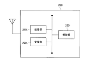
- FIG. 2 is a functional block configuration diagram of the UE 200.
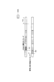
- FIG. 3 is a schematic diagram of the operation of the MGTA.
- FIG. 4 is a diagram showing an example of the relationship between the MG start timing when MGTA is applied and the reference timing used in the target cell.
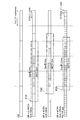
- FIG. 5 is a diagram illustrating an example of the MG start timing based on the operation example 1 and the operation example 2.
- FIG. 6 is a diagram illustrating a configuration example of an OFDM symbol.
- FIG. 7 is a diagram illustrating an example of a hardware configuration of the UE 200.
- FIG. 1 is an overall schematic configuration diagram of a wireless communication system 10 according to the present embodiment.
- the radio communication system 10 is a radio communication system according to Long Term Evolution (LTE) and 5G New Radio (NR), and includes a radio base station 100 (hereinafter, eNB100), a radio base station 110 (hereinafter, gNB110), and a user device. 200 (hereinafter, UE200).
- LTE Long Term Evolution
- NR 5G New Radio
- eNB100 radio base station 100
- gNB110 radio base station 110
- UE200 user device.
- the specific configuration of the wireless communication system 10 including the number of gNBs and UEs is not limited to the example shown in FIG.
- ENB 100 is a radio base station according to LTE, and forms one or a plurality of cells.
- the gNB 110 is a wireless base station according to 5G and forms one or a plurality of cells.
- the cell can constitute a Master Cell Group (MCG) and a Secondary Cell Group (SCG).
- the eNB 100 and the UE 200 execute wireless communication according to LTE using one or a plurality of carriers.
- the gNB 110 and the UE 200 execute wireless communication according to 5G using one or a plurality of carriers.
- eNB100, gNB110 and UE200 control a radio signal transmitted from a plurality of antenna elements to generate a more highly directive beam Massive MIMO, a carrier aggregation (CA) using a plurality of component carriers (CC), And dual connectivity (DC) for simultaneously transmitting component carriers between a plurality of NG-RAN nodes and the UE.
- Massive MIMO Massive MIMO
- CA carrier aggregation
- CC component carriers
- DC dual connectivity
- FIG. 2 is a functional block configuration diagram of the UE 200. As shown in FIG. 2, the UE 200 includes a transmission unit 210, a reception unit 220, and a control unit 230.
- Transmission section 210 transmits an uplink signal (UL signal) according to NR.
- UL signal uplink signal
- the receiving unit 220 receives a downlink signal (DL signal) according to the NR.
- the receiving unit 220 receives a reference signal (RS). More specifically, the receiving unit 220 receives Radio Link Monitoring R (RLM-RS) and the like.
- RS Reference Signal
- RLM-RS Radio Link Monitoring R
- the control unit 230 performs control on the UL signal transmitted by the transmission unit 210 and the DL signal received by the reception unit 220.
- control unit 230 performs measurement on a carrier (beam) transmitted from the eNB 100 or the gNB 110. Specifically, control section 230 performs measurement of cell quality using the measurement gap.
- Measurement gap is understood as the period during which no data and control signals are transmitted or received for the purpose of measuring the desired radio frequency (RF) quality or the like.
- An example is a period in which no data and control signals are transmitted or received due to radio frequency (RF) tuning (RF retuning).
- RF radio frequency
- PDSCH Physical Downlink Shared Channel
- PUSCH Physical Uplink Shared Channel
- control signals Physical Downlink Control Channel (PDCCH) and Physical Uplink Control Channel (PUCCH)
- Control unit 230 also performs measurement according to SS / PBCH ⁇ block ⁇ (SSB) -based ⁇ RRM ⁇ Measurement ⁇ Timing ⁇ Configuration (SMTC). Further, in the present embodiment, the control unit 230 corresponds to a function of moving the MG start timing ahead, specifically, MGTA. The operation based on MGTA will be further described later.
- the control unit 230 controls the start timing of the MG. Specifically, the control unit 230 applies the MG start timing according to the type of the reference timing used in the target cell.
- control unit 230 applies the MG start timing according to the type of the reference timing used for the measurement target cell for which the cell quality is to be measured.
- the reference timing is derived from a subframe period (1 ms) of the measurement target cell or a slot (for example, 0.25 ms, 0.5 ms) configuring the subframe.
- a slot may be called a unit time or TTI.
- control unit 230 can determine the start timing of the MG so as to match the boundary of the slot.
- the control unit 230 can also apply the MG start timing according to the SMTC (predetermined measurement method) cycle set in the measurement target cell. Specifically, control section 230 adjusts the start timing of the MG to the start timing of the SMTC window set for the cell of Frequency RangeFR2 (FR2) to be measured.
- SMTC Frequency RangeFR2
- control unit 230 may apply a start timing according to the cycle of the subframe set in the measurement target cell.
- the cell to be measured is LTE, it is preferable to apply such a method.
- control unit 230 can apply a start timing according to the type of reference timing used in the communication node instructing the MG. Specifically, the control unit 230 determines the MG set from the Secondary Node (SN) which is the communication node instructing the MG, such as Per-FR ⁇ gap for FR2 (details will be described later) when the EN-DC is executed. To the reference timing (slot boundary) on the SCG side. In the present embodiment, the gNB 110 when executing the EN-DC corresponds to the SN.
- SN Secondary Node
- FIG. 3 is a schematic diagram of the operation of MGTA. Specifically, FIG. 3 shows the start timing of SMTC (SSB in the figure, left inclined line portion) and the start timing of MG (right inclined line portion). FIG. 3 shows an example in which MG is 4 ms.
- the start timing of the MG and the start timing of the SMTC coincide, that is, at the same time, and the MG and the SMTC overlap on the time axis.
- the start timing of the MG and the start timing of the SMTC are the same, a case may occur where the RF retuning time of the MG overlaps with the time of the SMTC, and the SSB in the SMTC cannot be measured.
- MGTA values (advance time): 0ms / 0.25ms / 0.5ms. Specifically, 0 ms means that MG is not shifted forward. 0.5 ms is used when Frequency Range 1 (FR1) is included. 0.25 ms is used when the measurement target cell is only FR2 (only in the case of Per-FR gap for FR2).
- MG The following two types of MG are defined.
- Per-UE gap (same as LTE MG) ⁇ Per-FR gap
- LTE MG Long Term Evolution
- Per-FR gap In the Per-UE gap, only one MG can be set to UE 200 regardless of the frequency band of the measurement target cell. Also, data transmission / reception is not possible during MG.
- different MGs can be set for each of LTE and NR for FR1 measurement and for NR for FR2 measurement. For example, while MG is applied for NR FR2 measurement, communication in LTE and NR FR1 can be continued.
- the EN-DC when the EN-DC is executed, it is proposed that when Per-UE gap and MGTA is 0 ms, the timing is adjusted to the reference timing on the MCG side (LTE). Specifically, it has been proposed to start the MG in accordance with the subframe boundary on the LTE side. It is also proposed that, when the EN-DC is executed, if the Per-FR gap for FR1 measurement of the NR and MGTA is 0 ms, the timing is adjusted to the reference timing on the MCG side (LTE).
- FIG. 4 shows the MG when applying MGTA An example of a relationship between a start timing and a reference timing used in a target cell is shown. In FIG. 4, each horizontally long rectangle indicates a subframe or a slot.
- MGTA when MGTA is applied during execution of EN-DC, MG starts from timing T1, which is the middle of the LTE subframe (0.5 ms has elapsed).
- the UE 200 does not have a reference timing (slot boundary) that can be referred to at the timing T1 (another subcarrier interval). In the case of, there is a reference timing that can be referred to at the timing T1).
- SCS subcarrier interval
- the UE 200 can determine the MG start timing according to the measurement target cell for which the cell quality is to be measured (Operation Example 1).
- the UE 200 can determine the start timing based on the type of the reference timing used in the communication node (SN) indicating the MG (Operation Example 2).
- the start timing of the SMTC window set for the cell of FR2 to be measured or the measurement target MG start timing is determined based on a slot boundary of a cell (a cell using FR2 of NR).
- EN-DC is not executed (only LTE primary cell (PCell) operation)
- SMTC window set for the NR cell to be measured or based on the slot boundary of the NR cell
- the start timing of the MG is determined.
- MG start timing is determined using the result of SFN and Frame timing timing difference measurement (SFTD measurement) in which LTE eNB acquires the SSB transmission timing of the NR cell to be measured. May be done.
- SFTD measurement Frame timing timing difference measurement
- MGTA When MGTA is applied, a position shifted from the SMTC start timing by 1 to 4 slots ahead may be used as the MG start timing.
- the number of slots to be shifted is preferably changed according to the subcarrier interval (SCS). For example, a 0.5 ms MGTA is applied, and one slot can be used when the measurement target cell (NR cell) has a 30 kHz spacing, and two slots can be used when the measurement target cell (NR cell) has a 60 kHz spacing.
- SCS subcarrier interval
- the operation when operating as a standalone (SA) without dual connectivity, the operation may be the same as when EN-DC is not running. Further, when the measurement target cell is an LTE cell, the MG start timing may be determined in accordance with the LTE subframe (1 ms).
- FIG. 5 shows an example of the MG start timing based on the operation example 1 and the operation example 2. More specifically, FIG. 5 shows the start timing of the MG on the NR side when performing EN-DC.
- the MG start timing (see P10 in the figure) is adjusted to the LTE subframe.
- the MG is 4 ms and the SMTC window is 2 ms.
- the start timing of MG is determined based on the start timing of the SMTC window set for NR or the slot boundary of the NR cell (P20 in the figure). .
- the MG is 4 ms and the SMTC window is 3 ms.
- MGTA is 0.5 ms
- a position where the slot number (1 slot) corresponding to the MGTA is moved forward is set as the MG start timing.
- MGTA is applied, and also in the case of 120 kHz spacing, the start timing of MG is determined based on the start timing of the SMTC window set for NR or the slot boundary of the NR cell (P30 in the figure) ). In this case, MG is 3.5ms and SMTC window is 3ms.
- MGTA is 0.25 ms
- a position where the number of slots (two slots) corresponding to the MGTA is moved forward is the MG start timing.
- the start timing of MG is adjusted to the reference timing (slot boundary) of the cell on the SCG side.
- the start timing of the MG is adjusted to the timing on the LTE side.
- MGTA when MGTA is applied, a position shifted from the SMTC start timing by 1 to 4 slots ahead may be used as the MG start timing.
- the start timing of the MG may be determined based on the timing of the LTE subframe.
- the start timing of the MG is determined based on the timing of the LTE subframe, but the slot corresponding to the spacing of the subcarrier used in the NR cell is determined from the start timing.
- a position moved forward by a number is set as the MG start timing.
- the position where the slot number (1 slot) corresponding to the MGTA is moved forward is the MG start timing.
- the start timing of MG is the start timing of the SMTC window set for NR, or the slot boundary of the NR cell. (P30 in the figure).
- MGTA is 0.25 ms
- a position where the number of slots (two slots) corresponding to the MGTA is moved forward is the MG start timing.
- the OFDM symbol boundary is You may refer to it.
- FIG. 6 shows a configuration example of an OFDM symbol. Specifically, FIG. 6 shows an example of a 14 OFDM symbol. When the SCS has a spacing of 15 kHz, a boundary between the symbol # 6 and the symbol # 7 may be used as the reference timing.
- UE 200 applies MG start timing according to the type of reference timing used in the target cell. Therefore, it is possible to reliably avoid a state in which the reference timing that can be referred to for determining the MG start timing cannot be referred to. Thereby, it is possible to prevent the start timing accuracy of the MG in the UE 200 from being reduced.
- the start timing accuracy of the MG can be maintained.
- the UE 200 can apply the MG start timing according to the type of the reference timing used for the measurement target cell for which the cell quality is to be measured. Further, in the present embodiment, the MG start timing according to the SMTC (predetermined measurement scheme) cycle set in the measurement target cell or the subframe cycle set in the measurement target cell can be applied.
- SMTC predetermined measurement scheme
- the UE 200 can apply the start timing according to the type of the reference timing used in the communication node (SN or the like) indicating the MG.
- the operation example 1 and the operation example 2 described in the above embodiment may be combined.
- the operation example 1 may be applied to the stand-alone operation
- the operation example 2 may be applied to the execution of the EN-DC.
- the MG start timing may be adjusted to the frame timing or subframe timing used in the NR cell.
- each functional block may be realized using one device physically or logically coupled, or directly or indirectly (for example, two or more devices physically or logically separated). , Wired, wireless, etc.), and may be implemented using these multiple devices.
- the functional block may be realized by combining one device or the plurality of devices with software.
- Functions include: judgment, decision, judgment, calculation, calculation, processing, derivation, investigation, search, confirmation, reception, transmission, output, access, resolution, selection, selection, establishment, comparison, assumption, expectation, deemed, notification ( broadcasting), notifying, communicating, forwarding, configuring, reconfiguring, allocating, mapping, assigning, etc., but not limited to these .
- a functional block (configuration unit) that makes transmission function is called a transmitting unit (transmitting unit) or a transmitter (transmitter).
- the realization method is not particularly limited.
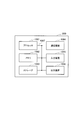
- FIG. 7 is a diagram illustrating an example of a hardware configuration of the UE 200.
- the device may be configured as a computer device including a processor 1001, a memory 1002, a storage 1003, a communication device 1004, an input device 1005, an output device 1006, a bus 1007, and the like.
- the term “apparatus” can be read as a circuit, a device, a unit, or the like.
- the hardware configuration of the device may be configured to include one or more devices illustrated in the drawing, or may be configured without including some devices.
- Each functional block of the device is realized by any hardware element of the computer device or a combination of the hardware components.
- the functions of the device are controlled by reading predetermined software (program) on hardware such as the processor 1001 and the memory 1002, so that the processor 1001 performs an operation and controls communication by the communication device 1004, It is realized by controlling at least one of reading and writing of data in the storage 1002 and the storage 1003.
- predetermined software program
- the processor 1001 performs an operation and controls communication by the communication device 1004, It is realized by controlling at least one of reading and writing of data in the storage 1002 and the storage 1003.
- the processor 1001 controls the entire computer by operating an operating system, for example.
- the processor 1001 may be configured by a central processing unit (CPU) including an interface with a peripheral device, a control device, an arithmetic device, a register, and the like.
- CPU central processing unit
- the processor 1001 reads out a program (program code), a software module, data, and the like from at least one of the storage 1003 and the communication device 1004 to the memory 1002, and executes various processes according to these.
- program program code
- a program that causes a computer to execute at least a part of the operation described in the above embodiment is used.
- the various processes described above may be executed by one processor 1001 or may be executed simultaneously or sequentially by two or more processors 1001.
- Processor 1001 may be implemented by one or more chips.
- the program may be transmitted from a network via a telecommunication line.
- the memory 1002 is a computer-readable recording medium, and includes, for example, at least one of Read Only Memory (ROM), Erasable Programmable ROM (EPROM), Electrically Erasable Programmable ROM (EEPROM), Random Access Memory (RAM), and the like. May be done.
- the memory 1002 may be called a register, a cache, a main memory (main storage device), or the like.
- the memory 1002 can store programs (program codes), software modules, and the like that can execute the method according to an embodiment of the present disclosure.
- the storage 1003 is a computer-readable recording medium, for example, an optical disc such as a Compact Disc ROM (CD-ROM), a hard disc drive, a flexible disc, a magneto-optical disc (for example, a compact disc, a digital versatile disc, a Blu-ray (Registered trademark) disk, a smart card, a flash memory (for example, a card, a stick, a key drive), a floppy (registered trademark) disk, and a magnetic strip.
- the storage 1003 may be called an auxiliary storage device.
- the above-described recording medium may be, for example, a database including at least one of the memory 1002 and the storage 1003, a server, or another appropriate medium.
- the communication device 1004 is hardware (transmitting / receiving device) for performing communication between computers via at least one of a wired network and a wireless network, and is also referred to as, for example, a network device, a network controller, a network card, a communication module, and the like.
- the communication device 1004 includes a high-frequency switch, a duplexer, a filter, a frequency synthesizer, and the like, for example, in order to realize at least one of frequency division duplex (Frequency Division Duplex: FDD) and time division duplex (Time Division Duplex: TDD). May be configured.
- FDD Frequency Division Duplex
- TDD Time Division Duplex
- the input device 1005 is an input device (for example, a keyboard, a mouse, a microphone, a switch, a button, a sensor, and the like) that receives an external input.
- the output device 1006 is an output device that performs output to the outside (for example, a display, a speaker, an LED lamp, and the like). Note that the input device 1005 and the output device 1006 may have an integrated configuration (for example, a touch panel).
- the devices such as the processor 1001 and the memory 1002 are connected by a bus 1007 for communicating information.
- the bus 1007 may be configured using a single bus, or may be configured using a different bus for each device.
- the device includes hardware such as a microprocessor, a digital signal processor (DSP), an application specific integrated circuit (ASIC), a programmable logic device (PLD), and a field programmable gate array (FPGA). And some or all of the functional blocks may be implemented by the hardware.
- the processor 1001 may be implemented using at least one of these pieces of hardware.
- notification of information is not limited to the aspect / embodiment described in the present disclosure, and may be performed using another method.
- information notification includes physical layer signaling (for example, Downlink Control Information (DCI), Uplink Control Information (UCI), upper layer signaling (for example, RRC signaling, Medium Access Control (MAC) signaling, and broadcast information (Master Information Block)).
- DCI Downlink Control Information
- UCI Uplink Control Information
- RRC signaling for example, RRC signaling, Medium Access Control (MAC) signaling, and broadcast information (Master Information Block)
- MIB System Information Block
- SIB System Information Block
- RRC signaling may be called an RRC message, for example, RRC connection setup (RRC Connection Setup). ) Message, an RRC connection reconfiguration message, etc.
- LTE Long Term Evolution
- LTE-A LTE-Advanced
- SUPER 3G IMT-Advanced
- 4th generation mobile communication system 4th generation mobile communication system
- 5G 5 th generation mobile communication system
- Future Radio Access FAA
- New Radio NR
- W-CDMA registered trademark
- GSM registered trademark
- CDMA2000 Code Division Multiple Access
- UMB Ultra Mobile Broadband
- IEEE 802.11 Wi-Fi (registered trademark))
- IEEE 802.16 WiMAX (R)
- IEEE 802.20 Ultra-WideBand (UWB), Bluetooth (R), and other appropriate systems
- at least a next generation system based on these systems It may be applied to one.
- a plurality of systems may be combined (for example, a combination of at least one of LTE and LTE-A with 5G) and applied.
- the specific operation described as being performed by the base station in the present disclosure may be performed by its upper node (upper node) in some cases.
- various operations performed for communication with a terminal are performed by the base station and other network nodes other than the base station (eg, MME or It is clear that this can be done by at least one of S-GW or the like (but not limited to these).
- MME Mobility Management Entity
- S-GW Packet Control Function
- Information and signals can be output from an upper layer (or lower layer) to a lower layer (or upper layer). Input and output may be performed via a plurality of network nodes.
- the input / output information may be stored in a specific place (for example, a memory) or may be managed using a management table. Information that is input and output can be overwritten, updated, or appended. The output information may be deleted. The input information may be transmitted to another device.
- the determination may be made based on a value (0 or 1) represented by one bit, a Boolean value (Boolean: true or false), or a comparison of numerical values (for example, a predetermined value). Value).
- Each aspect / embodiment described in the present disclosure may be used alone, may be used in combination, or may be used by switching with execution. Further, the notification of the predetermined information (for example, the notification of “X”) is not limited to being explicitly performed, and is performed implicitly (for example, not performing the notification of the predetermined information). Is also good.
- software, instructions, information, and the like may be transmitted and received via a transmission medium.
- a transmission medium For example, if the software uses at least one of wired technology (coaxial cable, fiber optic cable, twisted pair, digital subscriber line (DSL), etc.) and wireless technology (infrared, microwave, etc.), When transmitted from a server, or other remote source, at least one of these wired and / or wireless technologies is included within the definition of a transmission medium.
- the information, signals, etc. described in this disclosure may be represented using any of a variety of different technologies.
- data, instructions, commands, information, signals, bits, symbols, chips, etc. that can be referred to throughout the above description are not limited to voltages, currents, electromagnetic waves, magnetic or magnetic particles, light fields or photons, or any of these. May be represented by a combination of
- At least one of the channel and the symbol may be a signal (signaling).
- the signal may be a message.
- a component carrier (Component @ Carrier: CC) may be called a carrier frequency, a cell, a frequency carrier, or the like.
- system and “network” used in this disclosure are used interchangeably.
- the information, parameters, and the like described in the present disclosure may be expressed using an absolute value, may be expressed using a relative value from a predetermined value, or may be expressed using another corresponding information. May be represented.
- the radio resource may be indicated by an index.
- the names used for the above parameters are not limiting in any way. Further, equations and the like using these parameters may differ from those explicitly disclosed in the present disclosure.
- the various channels (eg, PUCCH, PDCCH, etc.) and information elements can be identified by any suitable name, so that the various names assigned to these various channels and information elements are limited in any way to the limited names is not.
- base station Base @ Station: BS
- wireless base station fixed station
- NodeB NodeB
- eNodeB eNodeB
- gNodeB gNodeB
- a base station may also be referred to as a macro cell, a small cell, a femto cell, a pico cell, or the like.
- a base station can accommodate one or more (eg, three) cells (also called sectors). If the base station accommodates a plurality of cells, the entire coverage area of the base station can be partitioned into a plurality of smaller areas, each smaller area being a base station subsystem (eg, a small indoor base station (RemoteReRadio Radio)). Head: RRH) can also provide communication services.
- a base station subsystem eg, a small indoor base station (RemoteReRadio Radio)
- Head: RRH can also provide communication services.
- cell refers to a base station that provides communication services in this coverage and / or a portion or the entire coverage area of at least one of the base station subsystems.
- MS Mobile station
- UE User equipment
- a mobile station can be a subscriber station, mobile unit, subscriber unit, wireless unit, remote unit, mobile device, wireless device, wireless communication device, remote device, mobile subscriber station, access terminal, mobile terminal, wireless terminal, by one of ordinary skill in the art. It may also be called a terminal, a remote terminal, a handset, a user agent, a mobile client, a client, or some other suitable term.
- At least one of the base station and the mobile station may be called a transmitting device, a receiving device, a communication device, or the like.
- at least one of the base station and the mobile station may be a device mounted on the mobile unit, the mobile unit itself, or the like.
- the moving object may be a vehicle (for example, a car, an airplane, etc.), an unmanned moving object (for example, a drone, a self-driving car, etc.), or a robot (maned or unmanned). ).
- at least one of the base station and the mobile station includes a device that does not necessarily move during a communication operation.
- at least one of the base station and the mobile station may be an Internet of Things (IoT) device such as a sensor.
- IoT Internet of Things
- the base station in the present disclosure may be read as a mobile station (user terminal, hereinafter the same).
- communication between a base station and a mobile station is replaced with communication between a plurality of mobile stations (for example, it may be called Device-to-Device (D2D), Vehicle-to-Everything (V2X), etc.).
- D2D Device-to-Device
- V2X Vehicle-to-Everything
- Each aspect / embodiment of the present disclosure may be applied to the configuration.
- the mobile station may have the function of the base station.
- words such as “up” and “down” may be read as words corresponding to communication between terminals (for example, “side”).
- an uplink channel, a downlink channel, and the like may be replaced with a side channel.
- the mobile station in the present disclosure may be read as a base station.
- the function that the mobile station has may be provided in the base station.
- connection means any direct or indirect connection or coupling between two or more elements that It may include the presence of one or more intermediate elements between the two elements "connected” or “coupled.”
- the coupling or connection between the elements may be physical, logical, or a combination thereof.
- connection may be read as “access”.
- two elements may be implemented using at least one of one or more electrical wires, cables, and printed electrical connections, and as some non-limiting and non-exhaustive examples, in the radio frequency domain. , Can be considered “connected” or “coupled” to each other, such as by using electromagnetic energy having wavelengths in the microwave and light (both visible and invisible) regions.
- the reference signal may be abbreviated as Reference Signal (RS), or may be referred to as a pilot depending on the standard applied.
- RS Reference Signal
- any reference to elements using designations such as "first,” “second,” etc., as used in the present disclosure, does not generally limit the quantity or order of those elements. These designations may be used in the present disclosure as a convenient way to distinguish between two or more elements. Thus, a reference to a first and second element does not mean that only two elements may be employed therein, or that the first element must somehow precede the second element.
- the term “A and B are different” may mean that “A and B are different from each other”.
- the term may mean that “A and B are different from C, respectively”.
- Terms such as “separate”, “coupled” and the like may be interpreted similarly to "different”.
- Wireless communication system 100 eNB 110 gNB 200 UE 210 transmitter 220 receiver 230 controller 1001 processor 1002 memory 1003 storage 1004 communication device 1005 input device 1006 output device 1007 bus
Landscapes
- Engineering & Computer Science (AREA)
- Computer Networks & Wireless Communication (AREA)
- Signal Processing (AREA)
- Mobile Radio Communication Systems (AREA)
Abstract
Description
図1は、本実施形態に係る無線通信システム10の全体概略構成図である。無線通信システム10は、Long Term Evolution(LTE)及び5G New Radio(NR)に従った無線通信システムであり、無線基地局100(以下、eNB100)、無線基地局110(以下、gNB110)及びユーザ装置200(以下、UE200)を含む。なお、gNB及びUEの数を含む無線通信システム10の具体的な構成は、図1に示した例に限定されない。
次に、無線通信システム10の機能ブロック構成について説明する。具体的には、UE200の機能ブロック構成について説明する。
次に、無線通信システム10の動作について説明する。具体的には、UE200によるMGの開始タイミングの決定動作について説明する。
まず、図3及び図4を参照して、MGTAの概要、及び従来のMGの開始タイミング例について説明する。
・Per-FR gap
Per-UE gapでは、測定対象セルの周波数帯に関係なく、UE200に設定できるMGは1つのみである。また、MG中はデータの送受信が不可である。
・デュアルコネクティビティではないスタンドアロン(SA)運用時
・MGTAの適用時
図4は、MGTAの適用時におけるMGの開始タイミングと、対象となるセルにおいて用いられている基準タイミングとの関係例を示す。図4において、横長の長方形それぞれは、サブフレームまたはスロットを示す。
次に、上述したような課題を解消するUE200の動作例について説明する。UE200は、上述したような課題を解消するため、MGの開始タイミングを適切に設定し、ネットワーク側が意図したタイミングにおいて、正確な周辺セルの品質を測定する。
本動作例では、測定対象セルに用いられている基準タイミングの種類に応じたMGの開始タイミングが適用される。
本動作例では、MGを指示する通信ノード(SN)において用いられている基準タイミングの種類に応じた開始タイミングが適用される。
上述した実施形態によれば、以下の作用効果が得られる。具体的には、UE200は、対象となるセルにおいて用いられている基準タイミングの種類に応じたMGの開始タイミングを適用する。このため、MGの開始タイミングを決定するために参照し得る基準タイミングが参照できない状態を確実に回避できる。これにより、UE200におけるMGの開始タイミング精度が低下することを防止できる。
以上、実施例に沿って本発明の内容を説明したが、本発明はこれらの記載に限定されるものではなく、種々の変形及び改良が可能であることは、当業者には自明である。
100 eNB
110 gNB
200 UE
210 送信部
220 受信部
230 制御部
1001 プロセッサ
1002 メモリ
1003 ストレージ
1004 通信装置
1005 入力装置
1006 出力装置
1007 バス
Claims (5)
- 測定ギャップの開始タイミングを制御する制御部を備え、
前記制御部は、対象となるセルにおいて用いられている基準タイミングの種類に応じた前記開始タイミングを適用するユーザ装置。 - 前記制御部は、セル品質の測定の対象となる測定対象セルに用いられている前記基準タイミングの種類に応じた前記開始タイミングを適用する請求項1に記載のユーザ装置。
- 前記制御部は、前記測定対象セルにおいて設定されている所定の測定方式の周期に応じた前記開始タイミングを適用する請求項2に記載のユーザ装置。
- 前記制御部は、前記測定対象セルにおいて設定されているサブフレームの周期に応じた前記開始タイミングを適用する請求項2に記載のユーザ装置。
- 前記制御部は、前記測定ギャップを指示する通信ノードにおいて用いられている前記基準タイミングの種類に応じた前記開始タイミングを適用する請求項1に記載のユーザ装置。
Priority Applications (5)
| Application Number | Priority Date | Filing Date | Title |
|---|---|---|---|
| US17/276,373 US20220046455A1 (en) | 2018-09-27 | 2018-09-27 | User equipment |
| PCT/JP2018/036152 WO2020065897A1 (ja) | 2018-09-27 | 2018-09-27 | ユーザ装置 |
| EP18934547.3A EP3860196B1 (en) | 2018-09-27 | 2018-09-27 | User equipment measurement gap timing |
| CN201880097305.5A CN112655240B (zh) | 2018-09-27 | 2018-09-27 | 用户装置 |
| JP2020547779A JP7145961B2 (ja) | 2018-09-27 | 2018-09-27 | ユーザ装置 |
Applications Claiming Priority (1)
| Application Number | Priority Date | Filing Date | Title |
|---|---|---|---|
| PCT/JP2018/036152 WO2020065897A1 (ja) | 2018-09-27 | 2018-09-27 | ユーザ装置 |
Publications (1)
| Publication Number | Publication Date |
|---|---|
| WO2020065897A1 true WO2020065897A1 (ja) | 2020-04-02 |
Family
ID=69950459
Family Applications (1)
| Application Number | Title | Priority Date | Filing Date |
|---|---|---|---|
| PCT/JP2018/036152 Ceased WO2020065897A1 (ja) | 2018-09-27 | 2018-09-27 | ユーザ装置 |
Country Status (5)
| Country | Link |
|---|---|
| US (1) | US20220046455A1 (ja) |
| EP (1) | EP3860196B1 (ja) |
| JP (1) | JP7145961B2 (ja) |
| CN (1) | CN112655240B (ja) |
| WO (1) | WO2020065897A1 (ja) |
Families Citing this family (4)
| Publication number | Priority date | Publication date | Assignee | Title |
|---|---|---|---|---|
| US12267897B2 (en) | 2018-08-09 | 2025-04-01 | Apple Inc. | Techniques in measurement gap configuration in new radio (NR) related communications |
| KR20210064351A (ko) * | 2018-09-28 | 2021-06-02 | 텔레호낙티에볼라게트 엘엠 에릭슨(피유비엘) | 측정 갭들과 부분적으로 중첩하는 유연한 할당 슬롯들에서의 동작들의 적응 |
| WO2021082009A1 (zh) * | 2019-11-01 | 2021-05-06 | Oppo广东移动通信有限公司 | 小区测量的方法、终端设备和网络设备 |
| EP4387113A1 (en) * | 2022-12-14 | 2024-06-19 | Stichting IMEC Nederland | Ultra-wideband pulse and ultra-wideband pulse-based ranging |
Citations (1)
| Publication number | Priority date | Publication date | Assignee | Title |
|---|---|---|---|---|
| JP2017041676A (ja) * | 2015-08-17 | 2017-02-23 | 株式会社Nttドコモ | ユーザ装置、基地局、測定方法及びギャップ区間決定方法 |
Family Cites Families (11)
| Publication number | Priority date | Publication date | Assignee | Title |
|---|---|---|---|---|
| US9084191B2 (en) * | 2011-01-20 | 2015-07-14 | Qualcomm Incorporated | Method and apparatus for determining timing information for cells |
| KR102369016B1 (ko) * | 2014-01-29 | 2022-03-03 | 삼성전자주식회사 | 이동 통신 시스템에서 복수의 캐리어를 이용하는 데이터 송수신 방법 및 장치 |
| US20170048108A1 (en) * | 2014-04-30 | 2017-02-16 | Lg Electronics Inc. | Method and apparatus for configuring measurement gap in wireless communication system |
| US20150327322A1 (en) * | 2014-05-08 | 2015-11-12 | Intel IP Corporation | Systems, devices, and methods for alignment procedures in dual-connectivity networks |
| US10045332B2 (en) * | 2014-05-09 | 2018-08-07 | Qualcomm Incorporated | UE autonomous radio resource configuration extension |
| RU2662448C1 (ru) * | 2014-08-08 | 2018-07-26 | ИНТЕЛ АйПи КОРПОРЕЙШН | Один промежуток измерений при возможности двойного асинхронного соединения |
| EP3200535A4 (en) * | 2014-09-25 | 2018-02-28 | Ntt Docomo, Inc. | User terminal, wireless communication system, and wireless communication method |
| KR20170081203A (ko) * | 2014-11-10 | 2017-07-11 | 텔레폰악티에볼라겟엘엠에릭슨(펍) | 듀얼 커넥티비티에서의 측정 갭 길이 구성을 위한 서브프레임 페어링의 방법 |
| WO2016182527A1 (en) * | 2015-05-14 | 2016-11-17 | Intel IP Corporation | Measurement gap configuration in dual connectivity enhancement |
| US10285156B2 (en) * | 2017-04-09 | 2019-05-07 | Qualcomm Incorporated | Dynamic measurement gap configuration for inter-frequency positioning measurements |
| US10412614B2 (en) * | 2017-10-20 | 2019-09-10 | Futurewei Technologies, Inc. | Coordination of measurement gaps across sets of multiple frequencies |
-
2018
- 2018-09-27 EP EP18934547.3A patent/EP3860196B1/en active Active
- 2018-09-27 CN CN201880097305.5A patent/CN112655240B/zh active Active
- 2018-09-27 WO PCT/JP2018/036152 patent/WO2020065897A1/ja not_active Ceased
- 2018-09-27 JP JP2020547779A patent/JP7145961B2/ja active Active
- 2018-09-27 US US17/276,373 patent/US20220046455A1/en not_active Abandoned
Patent Citations (1)
| Publication number | Priority date | Publication date | Assignee | Title |
|---|---|---|---|---|
| JP2017041676A (ja) * | 2015-08-17 | 2017-02-23 | 株式会社Nttドコモ | ユーザ装置、基地局、測定方法及びギャップ区間決定方法 |
Non-Patent Citations (6)
| Title |
|---|
| INTEL ET AL.: "CR on starting point to execute the measurement gap", 3GPP TSG-RAN4 MEETING #88 R4-1810212, 10 August 2018 (2018-08-10), pages 1 - 6, XP051579215 * |
| LG ELECTRONICS ET AL.: "Discussion on UE behavior in the slot immediately before/after measurement gap", 3GPP TSG-RAN WG4 #88 MEETING R4-1810220, 10 August 2018 (2018-08-10), pages 1 - 9, XP051579223 * |
| NTT DOCOMO, INC. ET AL.: "The definition of measurement gap starting point", 3GPP TSG RAN WG4 MEETING #88BIS R4-1812706, 28 September 2018 (2018-09-28), pages 1 - 3, XP051581418 * |
| See also references of EP3860196A4 * |
| ZTE ET AL.: "Discussion on UL transmission after measurement gap", 3GPP TSG-RAN WG4 MEETING #88 R4-1810742, 10 August 2018 (2018-08-10), pages 1 - 4, XP051579668 * |
| ZTE ET AL.: "Way forward on UE behavior before or after measurement gap", 3GPP TSG-RAN WG4 MEETING #88 R4-1811869, 29 August 2018 (2018-08-29), pages 1 - 9, XP051580707 * |
Also Published As
| Publication number | Publication date |
|---|---|
| JP7145961B2 (ja) | 2022-10-03 |
| US20220046455A1 (en) | 2022-02-10 |
| EP3860196A1 (en) | 2021-08-04 |
| EP3860196B1 (en) | 2025-04-09 |
| EP3860196A4 (en) | 2022-05-25 |
| CN112655240B (zh) | 2023-11-21 |
| JPWO2020065897A1 (ja) | 2021-08-30 |
| CN112655240A (zh) | 2021-04-13 |
Similar Documents
| Publication | Publication Date | Title |
|---|---|---|
| JP7510408B2 (ja) | 端末、通信方法、及びシステム | |
| WO2021199346A1 (ja) | 端末 | |
| WO2020188829A1 (ja) | ユーザ装置及び通信方法 | |
| WO2021064875A1 (ja) | 端末及び送信方法 | |
| JP7145961B2 (ja) | ユーザ装置 | |
| US12432031B2 (en) | Terminal | |
| WO2020065802A1 (ja) | ユーザ装置 | |
| US12088515B2 (en) | User equipment | |
| JP7312837B2 (ja) | 端末 | |
| WO2020065779A1 (ja) | ユーザ装置 | |
| WO2020144834A1 (ja) | ユーザ装置及び通信方法 | |
| US20220124708A1 (en) | Radio base station and user equipment | |
| WO2021029075A1 (ja) | 端末及び通信方法 | |
| WO2020170404A1 (ja) | ユーザ装置 | |
| WO2021005716A1 (ja) | 端末及び送信方法 | |
| WO2020222269A1 (ja) | ユーザ装置及び通信方法 | |
| JP7100195B2 (ja) | ユーザ装置 | |
| RU2787468C1 (ru) | Пользовательское оборудование | |
| WO2020065801A1 (ja) | ユーザ装置 | |
| WO2020084745A1 (ja) | ユーザ装置 | |
| WO2021064970A1 (ja) | 端末及び測定方法 | |
| WO2020165957A1 (ja) | 通信装置 |
Legal Events
| Date | Code | Title | Description |
|---|---|---|---|
| 121 | Ep: the epo has been informed by wipo that ep was designated in this application |
Ref document number: 18934547 Country of ref document: EP Kind code of ref document: A1 |
|
| ENP | Entry into the national phase |
Ref document number: 2020547779 Country of ref document: JP Kind code of ref document: A |
|
| NENP | Non-entry into the national phase |
Ref country code: DE |
|
| ENP | Entry into the national phase |
Ref document number: 2018934547 Country of ref document: EP Effective date: 20210428 |
|
| WWG | Wipo information: grant in national office |
Ref document number: 2018934547 Country of ref document: EP |