WO2020066050A1 - 締結構造体 - Google Patents
締結構造体 Download PDFInfo
- Publication number
- WO2020066050A1 WO2020066050A1 PCT/JP2019/004418 JP2019004418W WO2020066050A1 WO 2020066050 A1 WO2020066050 A1 WO 2020066050A1 JP 2019004418 W JP2019004418 W JP 2019004418W WO 2020066050 A1 WO2020066050 A1 WO 2020066050A1
- Authority
- WO
- WIPO (PCT)
- Prior art keywords
- battery
- fastening
- fastened
- negative electrode
- positive electrode
- Prior art date
- Legal status (The legal status is an assumption and is not a legal conclusion. Google has not performed a legal analysis and makes no representation as to the accuracy of the status listed.)
- Ceased
Links
Images


Classifications
-
- H—ELECTRICITY
- H01—ELECTRIC ELEMENTS
- H01M—PROCESSES OR MEANS, e.g. BATTERIES, FOR THE DIRECT CONVERSION OF CHEMICAL ENERGY INTO ELECTRICAL ENERGY
- H01M50/00—Constructional details or processes of manufacture of the non-active parts of electrochemical cells other than fuel cells, e.g. hybrid cells
- H01M50/10—Primary casings; Jackets or wrappings
- H01M50/147—Lids or covers
- H01M50/148—Lids or covers characterised by their shape
- H01M50/15—Lids or covers characterised by their shape for prismatic or rectangular cells
-
- H—ELECTRICITY
- H01—ELECTRIC ELEMENTS
- H01M—PROCESSES OR MEANS, e.g. BATTERIES, FOR THE DIRECT CONVERSION OF CHEMICAL ENERGY INTO ELECTRICAL ENERGY
- H01M50/00—Constructional details or processes of manufacture of the non-active parts of electrochemical cells other than fuel cells, e.g. hybrid cells
- H01M50/10—Primary casings; Jackets or wrappings
- H01M50/147—Lids or covers
- H01M50/166—Lids or covers characterised by the methods of assembling casings with lids
-
- H—ELECTRICITY
- H01—ELECTRIC ELEMENTS
- H01M—PROCESSES OR MEANS, e.g. BATTERIES, FOR THE DIRECT CONVERSION OF CHEMICAL ENERGY INTO ELECTRICAL ENERGY
- H01M10/00—Secondary cells; Manufacture thereof
- H01M10/04—Construction or manufacture in general
- H01M10/0431—Cells with wound or folded electrodes
-
- H—ELECTRICITY
- H01—ELECTRIC ELEMENTS
- H01M—PROCESSES OR MEANS, e.g. BATTERIES, FOR THE DIRECT CONVERSION OF CHEMICAL ENERGY INTO ELECTRICAL ENERGY
- H01M50/00—Constructional details or processes of manufacture of the non-active parts of electrochemical cells other than fuel cells, e.g. hybrid cells
- H01M50/10—Primary casings; Jackets or wrappings
- H01M50/102—Primary casings; Jackets or wrappings characterised by their shape or physical structure
- H01M50/103—Primary casings; Jackets or wrappings characterised by their shape or physical structure prismatic or rectangular
-
- H—ELECTRICITY
- H01—ELECTRIC ELEMENTS
- H01M—PROCESSES OR MEANS, e.g. BATTERIES, FOR THE DIRECT CONVERSION OF CHEMICAL ENERGY INTO ELECTRICAL ENERGY
- H01M50/00—Constructional details or processes of manufacture of the non-active parts of electrochemical cells other than fuel cells, e.g. hybrid cells
- H01M50/10—Primary casings; Jackets or wrappings
- H01M50/172—Arrangements of electric connectors penetrating the casing
- H01M50/174—Arrangements of electric connectors penetrating the casing adapted for the shape of the cells
- H01M50/176—Arrangements of electric connectors penetrating the casing adapted for the shape of the cells for prismatic or rectangular cells
-
- H—ELECTRICITY
- H01—ELECTRIC ELEMENTS
- H01M—PROCESSES OR MEANS, e.g. BATTERIES, FOR THE DIRECT CONVERSION OF CHEMICAL ENERGY INTO ELECTRICAL ENERGY
- H01M50/00—Constructional details or processes of manufacture of the non-active parts of electrochemical cells other than fuel cells, e.g. hybrid cells
- H01M50/50—Current conducting connections for cells or batteries
- H01M50/543—Terminals
- H01M50/547—Terminals characterised by the disposition of the terminals on the cells
- H01M50/55—Terminals characterised by the disposition of the terminals on the cells on the same side of the cell
-
- H—ELECTRICITY
- H01—ELECTRIC ELEMENTS
- H01M—PROCESSES OR MEANS, e.g. BATTERIES, FOR THE DIRECT CONVERSION OF CHEMICAL ENERGY INTO ELECTRICAL ENERGY
- H01M50/00—Constructional details or processes of manufacture of the non-active parts of electrochemical cells other than fuel cells, e.g. hybrid cells
- H01M50/50—Current conducting connections for cells or batteries
- H01M50/543—Terminals
- H01M50/552—Terminals characterised by their shape
- H01M50/553—Terminals adapted for prismatic, pouch or rectangular cells
-
- H—ELECTRICITY
- H01—ELECTRIC ELEMENTS
- H01M—PROCESSES OR MEANS, e.g. BATTERIES, FOR THE DIRECT CONVERSION OF CHEMICAL ENERGY INTO ELECTRICAL ENERGY
- H01M50/00—Constructional details or processes of manufacture of the non-active parts of electrochemical cells other than fuel cells, e.g. hybrid cells
- H01M50/50—Current conducting connections for cells or batteries
- H01M50/543—Terminals
- H01M50/564—Terminals characterised by their manufacturing process
-
- Y—GENERAL TAGGING OF NEW TECHNOLOGICAL DEVELOPMENTS; GENERAL TAGGING OF CROSS-SECTIONAL TECHNOLOGIES SPANNING OVER SEVERAL SECTIONS OF THE IPC; TECHNICAL SUBJECTS COVERED BY FORMER USPC CROSS-REFERENCE ART COLLECTIONS [XRACs] AND DIGESTS
- Y02—TECHNOLOGIES OR APPLICATIONS FOR MITIGATION OR ADAPTATION AGAINST CLIMATE CHANGE
- Y02E—REDUCTION OF GREENHOUSE GAS [GHG] EMISSIONS, RELATED TO ENERGY GENERATION, TRANSMISSION OR DISTRIBUTION
- Y02E60/00—Enabling technologies; Technologies with a potential or indirect contribution to GHG emissions mitigation
- Y02E60/10—Energy storage using batteries
-
- Y—GENERAL TAGGING OF NEW TECHNOLOGICAL DEVELOPMENTS; GENERAL TAGGING OF CROSS-SECTIONAL TECHNOLOGIES SPANNING OVER SEVERAL SECTIONS OF THE IPC; TECHNICAL SUBJECTS COVERED BY FORMER USPC CROSS-REFERENCE ART COLLECTIONS [XRACs] AND DIGESTS
- Y02—TECHNOLOGIES OR APPLICATIONS FOR MITIGATION OR ADAPTATION AGAINST CLIMATE CHANGE
- Y02P—CLIMATE CHANGE MITIGATION TECHNOLOGIES IN THE PRODUCTION OR PROCESSING OF GOODS
- Y02P70/00—Climate change mitigation technologies in the production process for final industrial or consumer products
- Y02P70/50—Manufacturing or production processes characterised by the final manufactured product
Definitions
- the present invention relates to a fastening structure having a resin member between a fastening member and a member to be fastened.
- Patent Literature 1 in a power storage element having a resin member gasket between an external terminal serving as a fastening member and a case serving as a member to be fastened, the external terminal facing the case has a protrusion on a facing surface, Patent Literature 1 discloses a power storage element having a protrusion also in a gasket body in a region corresponding to the above. With this configuration, a technique has been disclosed in which the surface pressure applied to the gasket is improved, and the sealing between the external terminal and the case is improved.
- Patent Literature 1 in the compression region of the gasket where the distance between the external terminal and the case is minimized, the protrusion provided on the gasket is further compressed, and the compressed gasket member escapes to the periphery. . At this time, the gasket is easier to escape into the space without the case than the protrusion provided on the external terminal.
- the seal portion may be substantially only the portion where the distance between the external terminal and the case is minimized. In many cases, there is a problem that it is difficult to obtain a seal area.
- An object of the present invention is to provide a fastening structure in which a member of a gasket compressed as described above is prevented from escaping to the surroundings, thereby securing a sealing area.
- a fastening structure includes a container, a fastening member provided through a through hole provided in the container, and a fastening member provided between the fastening member and the container.
- An insulating member (resin-made member) provided, wherein the fastening member has an exposed portion exposed from the container and a penetrating portion penetrating through the through-hole, and the exposed portion is
- the container has an opposing surface facing the outer surface of the container via an insulating member, and between the opposing surface and the outer surface, there is one compression region where the distance is minimum, and a position that does not overlap with the compression region.
- a projection protruding from the opposing surface toward the outer surface or protruding from the outer surface toward the opposing surface is provided.
- Sectional view of the fastening structure of the first embodiment Appearance perspective view of storage element Exploded perspective view of a storage element Exploded perspective view of a wound electrode group
- FIG. 1 is a sectional view of the fastening structure 101.
- the fastening structure 101 of the present embodiment is used in a device such as a hydraulic or hydraulic machine which needs to maintain airtightness so that contents such as liquid sealed in a container do not leak.
- the fastening structure 101 includes a fastening member 70, a member 80 to be fastened by the fastening member 70, and a resin member 90 sandwiched between the fastening member 70 and the member 80.
- the member to be fastened 80 is, for example, a container for containing a liquid or a lid for sealing the container, and is composed of one or a plurality of members.
- the member to be fastened 80 has a through hole.
- the fastening member 70 includes a through-hole 66 in the through-hole of the member to be fastened 80, an exposed portion 12 (14) which is provided at both ends of the through-hole 66 and sandwiches the to-be-fastened member 80 from both sides, and a caulking portion 13.
- the exposed part 12 (14) is located outside the container, and the caulking part 13 is located inside the container.
- the caulked portion 13 and the penetrating portion 66 are inserted into the through hole from the outside of the container, the caulked portion 13 is expanded in the radial direction of the through hole, and press working or the like is performed so that the member to be fastened 80 is fastened by the fastening member 70.
- the fastening member 70 for example, a metal material such as an aluminum alloy can be used.
- the exposed portion 12 (14) has a larger diameter than the through portion 66, that is, extends to the outside of the through portion 66 in the radial direction about the through portion 66 as an axis.
- the caulked portion 13 is also spread outside the penetrating portion 66 by being caulked by the member to be fastened 80. With such a structure, the member to be fastened 80 is sandwiched between the exposed portion 12 (14) and the swaged portion 13.
- the resin member 90 is provided between the fastening member 70 and the member to be fastened 80, for example, between the exposed portion 12 (14) and the member to be fastened 80 as shown in FIG. It is provided between.
- the resin member 90 is provided, for example, for the purpose of maintaining insulation between the fastening member 70 and the member to be fastened 80 or for maintaining the hermeticity of the container.
- the resin member 90 is formed by injecting or pressing a resin material such as polybutylene terephthalate, polyphenylene sulfide, or a perfluoroalkoxy fluororesin.
- the exposed portion 12 faces the outer surface of the member to be fastened 80 via the resin member 90.
- the surface 71 is formed.
- the sealing property of this portion is important, and the space between the exposed portion 12 (14) and the member to be fastened 80 must be effectively sealed by the resin member 90.
- the sealing property can be adjusted by adjusting the height 50a of the compression projection 50 of the compression projection 50.
- the compression region 72 is located inside the end portion 13a of the caulked portion 13 (in the radial direction inside the through portion 66). As a result, a caulking force is applied to the compression region 72, and the sealing property can be effectively generated.
- the fastening force by swaging is a region in which the portion from the center of the shaft to the end 13a of the swaging portion 13 stably acts in the radial direction about the through portion 66 of the fastening member 70 as an axis. The presence of the compression region 72 in the region allows the resin member 90 to be stably compressed over a long period of time.
- the convex portion 60 slightly compresses the resin member 90 outside the end portion 13a of the caulked portion 13, and it is possible to suppress the occurrence of a gap due to the action of light compression even at the time of a vibration shock.
- a resin member 90 and a convex portion 60 protruding toward the opposing surface 71 are provided on the surface on the opposing surface 71 side of the member 80 to be fastened.
- the convex portion 60 is provided at a position that does not overlap with the compression region 72, for example, outside the compression region 72 in the radial direction with the through portion 66 as an axis.
- the protruding portion 60 is provided outside the end portion 13a of the caulked portion 13 in the radial direction.
- the meat escape preventing effect can be generated without hindering the sealing effect by the compression region 72 as much as possible.
- the relief of the resin member 90 compressed in the compression region 72 by the action of the lightly compressed region by the convex portion 60, particularly to the radially outer side around the through portion 66 is suppressed, and the sealing area is secured by tightly contacting the fastening member 70 and the member to be fastened 80 with the resin member 90.
- the convex part height 60a is too high, for example, if the distance between the convex part 60 and the opposing surface 71 becomes smaller than the distance between the opposing surface 71 and the member 80 in the compression region 72, the fastening member 70 and the lid There is a plurality of compression regions 72 where the distance from the resin member 6 is the minimum, and the elastic deformation of the resin member 90 does not occur properly, and there is a possibility that the sealing performance is reduced due to dispersion of the repulsive load. is there. For this reason, it is preferable that the height 60a of the convex portion is set so that the distance between the convex portion 60 and the opposing surface 71 is not smaller than the distance between the opposing surface 71 and the member 80 in the compression region 72.
- the repulsion load obtained when the resin member 90 is compressed increases.
- the escape of the resin member 90 becomes more remarkable.
- the repulsion load is considered as the seal surface pressure obtained by dividing the repulsion load by the area of the compression region 72, the better the seal surface pressure is, the more the compression region 72 is provided.
- the repulsion load is too high, the load applied to the caulking portion 13 of the fastening member 70 increases, so that the caulking diameter is distorted or the load at the time of caulking needs to be increased, so that the fastening member 70 buckles. As a result, a fastening failure occurs.
- one compression region 72 in which the distance between the fastening member 70 and the lid 6 is minimum is desirable, and thus the height 60a of the projection 60 is equal to the height of the compression projection of the compression projection 50. Preferably, it is lower than 50a.
- FIG. 1 illustrates the fastening structure 101, it is effective to use the fastening structure 101 for a secondary battery such as a lithium ion secondary battery.
- the fastening member 70 is, for example, a positive electrode external terminal (exposed portion 14) or a negative electrode external terminal (exposed portion 12).
- the resin member (insulating member) 90 is a gasket.
- the positive external terminal or the negative external terminal which is the fastening member 70, has a role as a terminal for electrically connecting the winding group (the power storage element) 3 to the outside of the battery can 1. Therefore, since it becomes an electric passage, it is necessary to maintain insulation from the battery cover 6, and the battery cover 6 is provided on the battery cover 6 via the gasket 5 (resin member 90) or the insulating plate 7. Since this is a separate member, a path connecting the inside and the outside of the battery can 1 is formed in this part, so that it is important to maintain the sealing property by the gasket 5.
- a winding group 3 is housed in the battery can 1, and the winding group 3 is electrically connected to a positive external terminal and a negative external terminal, which are fastening portions 70.
- the positive electrode current collector plate 44 and the negative electrode current collector plate 24 are electrically connected to the outside of the secondary battery.
- the battery cover 6 needs to be insulated from the positive electrode external terminal and the negative electrode external terminal, and the positive electrode current collector 44 and the negative electrode current collector 24 electrically connected thereto.
- a gasket 5, which is a resin member 90, is provided between the positive external terminal and the negative external terminal, and an insulating plate 7 is provided between the battery cover 6, the positive current collector 44, and the negative current collector 24. ing.
- the gasket 5 has a through-hole similarly to the member to be fastened 80 such as the battery lid 6, and the through-hole 66 of the negative electrode external terminal exposed portion 12 and the positive electrode external terminal exposed portion 14 penetrates.
- the gasket 5 has a portion interposed between the through portion 66 and the inner wall of the through hole of the battery lid 6, and a portion interposed between the negative electrode external terminal exposed portion 12, the positive electrode external terminal exposed portion 14, and the outer surface of the battery lid 6.
- a convex portion having a portion and preventing meat escape is provided in the latter portion.
- it may be provided in the former part, it is preferably provided in the latter part as shown in FIG. 1 from the viewpoint of parts processing and ease of assembly.
- FIG. 2 is an external view of the secondary battery when the fastening structure 101 is used for the secondary battery 100.
- the secondary battery 100 has an electrolytic solution inside the container, and it is necessary to keep the inside airtight so that the electrolytic solution does not leak.
- a power storage element secondary battery
- the secondary battery 100 includes the battery can 1 and the battery lid 6.
- the battery can 1 and the battery lid 6 are made of a metal material such as an aluminum alloy, for example, and are formed by performing deep drawing and pressing.
- a wound (electrode) group 3 (FIG. 3) is built in the battery can 1, and the opening 1 a of the battery can 1 is sealed with a battery lid 6.
- the battery lid 6 has a substantially rectangular flat plate shape, and is welded so as to cover the opening 1a of the battery can 1, thereby sealing the battery can 1.
- the battery lid 6 is provided with a positive electrode external terminal exposed portion 14 and a negative electrode external terminal exposed portion 12 fixed to the battery lid 6 by a gasket (insulating member) 5 formed by insert molding or press molding.
- the wound (electrode) group 3 is charged via the positive electrode external terminal exposed portion 14 and the negative electrode external terminal exposed portion 12, and power is supplied to an external load.
- a gas discharge valve 10 is provided integrally with the battery lid 6, and when the pressure in the battery container rises, the gas discharge valve 10 opens to discharge gas from the inside and reduce the pressure in the battery container. Thereby, the safety of the secondary battery 100 is ensured.
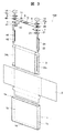
- FIG. 3 is an exploded perspective view of the secondary battery 100.
- the battery can 1 of the secondary battery 100 includes a rectangular bottom surface 1d, a wide side surface 1b rising from a pair of long sides of the bottom surface 1d, a narrow side surface 1c rising from a pair of short sides of the bottom surface 1d, and these wide side surfaces 1b. And an opening 1a opened upward at the upper end of the narrow side surface 1c.
- a wound (electrode) group 3 is accommodated in the battery can 1 via an insulating protective film 2.
- the wound (electrode) group 3 is configured by winding a strip-shaped electrode into a flat shape, and has a pair of curved portions facing each other having a semicircular cross section, and is continuously provided between the pair of curved portions. And a flat portion to be formed.
- the wound (electrode) group 3 is inserted into the battery can 1 from one of the curved portions and faces the bottom surface 1d so that the direction of the wound axis extends along the width direction of the battery can 1, and the other curved portion has It is arranged on the opening 1a side.
- the positive electrode foil exposed portion 34 c of the wound (electrode) group 3 is electrically connected to the positive electrode external terminal exposed portion 14 provided on the battery lid 6 via the positive electrode current collector 44. Further, the negative electrode foil exposed portion 32 c of the wound (electrode) group 3 is electrically connected to the negative electrode external terminal exposed portion 12 provided on the battery lid 6 via the negative electrode current collector 24.
- power is supplied from the winding (electrode) group 3 to the external load via the positive electrode current collector plate 44 and the negative electrode current collector plate 24, and the winding (electrode) is wound via the positive electrode current collector plate 44 and the negative electrode current collector plate 24.
- the electrode 3 is supplied with externally generated power and charged.
- the gasket 5 and the insulating plate 7 It is provided on the lid 6. After injecting the electrolytic solution into the battery can 1 from the liquid inlet 9, the liquid stopper 11 is joined to the battery lid 6 by laser welding to seal the liquid inlet 9, and the flat wound secondary battery is sealed. The battery 100 is sealed.
- the positive electrode current collector plate 44 for example, an aluminum alloy can be used, and as a material for forming the negative electrode current collector plate 24, for example, a copper alloy can be used.
- the material for forming the gasket (insulating member) 5 include resin materials having an insulating property such as polybutylene terephthalate, polyphenylene sulfide, and perfluoroalkoxy fluororesin.
- the battery cover 6 is provided with a liquid inlet 9 for injecting the electrolyte into the battery container.
- the liquid inlet 9 is provided with a liquid stopper after the electrolyte is injected into the battery container. 11 seals.
- a non-aqueous electrolytic solution in which a lithium salt such as lithium hexafluorophosphate (LiPF 6 ) is dissolved in a carbonate-based organic solvent such as ethylene carbonate is used. Can be applied.
- the positive electrode external terminal exposed portion 14 and the negative electrode external terminal exposed portion 12 have a welded joint to be welded to a bus bar or the like.
- the welded joint has a flat surface disposed above the gasket 5 and parallel to the outer surface of the battery cover 6, and a bus bar or the like is brought into contact with the flat surface and welded. .
- the negative electrode connecting portion 12a and the positive electrode connecting portion 14a protrude from the lower surfaces of the negative electrode external terminal exposed portion 12 and the positive electrode external terminal exposed portion 14, respectively, and the tips are inserted into the negative electrode side through hole 26 and the positive electrode side through hole 46 of the battery lid 6. It has a possible cylindrical shape.
- the negative electrode connecting portion 12a and the positive electrode connecting portion 14a penetrate the battery lid 6, and the negative electrode current collecting plate 24, the negative electrode current collecting plate base 21 of the positive electrode current collecting plate 44, and the positive electrode current collecting plate base 41, It protrudes inward, and its tip is crimped to integrally fix the negative electrode external terminal exposed portion 12, the positive electrode external terminal exposed portion 14, the negative electrode current collector 24, and the positive electrode current collector 44 to the battery lid 6. .
- a gasket 5 is interposed between the negative electrode external terminal exposed portion 12, the positive electrode external terminal exposed portion 14, and the battery lid 6, and is provided between the negative electrode current collector 24, the positive electrode current collector 44 and the battery lid 6.
- the negative electrode current collector plate base 21 and the positive electrode current collector plate base 41 have a negative electrode side opening hole 23 and a positive electrode side opening hole 43 into which the negative electrode connection part 12a and the positive electrode connection part 14a are inserted, respectively.
- the positive electrode current collector 44 and the negative electrode current collector 24 extend toward the bottom surface 1 d along the wide side surface 1 b of the battery can 1, and the positive electrode foil exposed portion 34 c and the negative electrode foil exposed portion of the wound (electrode) group 3 It has a positive-side connection end 42 and a negative-side connection end 22 that are connected to each other in a state of being overlapped with each other.
- An insulating protective film is provided around the wound (electrode) group 3 with the direction along the flat surface of the wound (electrode) group 3 and the direction perpendicular to the winding axis direction of the wound (electrode) group 3 as the central axis direction. 2 is wound.
- the insulating protective film 2 is made of one sheet or a plurality of film members made of a synthetic resin such as PP (polypropylene), for example, in a direction parallel to the flat surface of the winding (electrode) group 3 and in a winding axis direction. It has a length that can be wound around the direction perpendicular to the winding center.
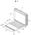
- FIG. 4 is an exploded perspective view showing a state where a part of the wound electrode group is developed.
- the wound (electrode) group 3 is formed by winding flat between the negative electrode 32 and the positive electrode 34 via the separators 33 and 35.
- the outermost electrode is the negative electrode 32, and the separators 33 and 35 are further wound outside the negative electrode 32.
- the separators 33 and 35 have a role of insulating between the positive electrode 34 and the negative electrode 32.
- the portion of the negative electrode 32 to which the negative electrode mixture layer 32b is applied is larger in the width direction than the portion of the positive electrode 34 to which the positive electrode mixture layer 34b is applied, so that the portion where the positive electrode mixture layer 34b is applied is
- the negative electrode mixture layer 32b is always sandwiched between portions where the negative electrode mixture layer 32b is applied.
- the exposed portion of the positive electrode foil 34c and the exposed portion of the negative electrode foil 32c are bundled at a plane portion and connected by welding or the like.
- the separators 33 and 35 are wider in the width direction than the portion where the negative electrode mixture layer 32b is applied, the separators 33 and 35 are wound at positions where the metal foil surfaces at the ends are exposed at the positive electrode exposed portion 34c and the negative electrode exposed portion 32c. Therefore, it does not hinder bundled welding.
- the positive electrode 34 has a positive electrode active material mixture on both sides of a positive electrode foil 34a serving as a positive electrode current collector, and has a positive electrode exposed at the one end in the width direction of the positive electrode foil where the positive electrode active material mixture is not applied.
- a portion 34c is provided.
- the negative electrode 32 has a negative electrode active material mixture on both sides of a negative electrode foil 32a serving as a negative electrode current collector, and has an exposed negative electrode foil on which the negative electrode active material mixture is not applied at the other end in the width direction of the negative electrode foil.
- a portion 32c is provided.
- the exposed portion of the positive electrode foil 34c and the exposed portion of the negative electrode foil 32c are regions where the metal surface of the electrode foil is exposed, and are wound so as to be disposed on one side and the other side in the winding axis direction.
- PVDF polyvinylidene fluoride
- N amorphous carbon powder
- NMP kneading -methylpyrrolidone
- Natural graphite capable of inserting and removing lithium ions, and various artificial graphite materials A carbonaceous material such as coke, a compound such as Si or Sn (for example, SiO, TiSi 2 or the like), or a composite material thereof, and the particle shape of the material may also be scale-like, spherical, fibrous, massive, etc. There is no restriction.
- the positive electrode 34 10 parts by weight of flake graphite as a conductive material and 10 parts by weight of PVDF as a binder are added to 100 parts by weight of lithium manganate (chemical formula LiMn 2 O 4 ) as a positive electrode active material. Then, a positive electrode mixture was prepared by adding and kneading NMP as a dispersion solvent thereto. This positive electrode mixture was applied to both sides of a 20 ⁇ m-thick aluminum foil (positive electrode foil) except for a welded portion (positive electrode uncoated portion). Thereafter, through a drying, pressing, and cutting process, a positive electrode 31 having a thickness of 90 ⁇ m and a positive electrode active material application portion not containing an aluminum foil was obtained.
- LiMn 2 O 4 lithium manganate
- lithium manganate is used as the positive electrode active material.
- other lithium manganate having a spinel crystal structure a lithium manganese composite oxide in which a part is replaced or doped with a metal element, Lithium cobalt oxide or lithium titanate having a crystal structure, or a lithium-metal composite oxide in which a part thereof is substituted or doped with a metal element may be used.
- PVDF polytetrafluoroethylene
- polyethylene polystyrene
- polybutadiene butyl rubber
- nitrile rubber styrene
- polymers such as butadiene rubber, polysulfide rubber, nitrocellulose, cyanoethylcellulose, various latexes, acrylonitrile, vinyl fluoride, vinylidene fluoride, propylene fluoride, chloroprene, acrylic resin, and mixtures thereof.
- PTFE polytetrafluoroethylene
- polystyrene polystyrene
- polybutadiene butyl rubber
- nitrile rubber styrene
- styrene Use polymers such as butadiene rubber, polysulfide rubber, nitrocellulose, cyanoethylcellulose, various latexes, acrylonitrile, vinyl fluoride, vinylidene fluoride, propylene fluoride, chloroprene, acrylic resin, and
- the shaft core for example, a material obtained by winding a resin sheet having higher bending rigidity than any of the positive electrode foil, the negative electrode foil, and the separators 33 and 35 can be used.
- the positive electrode external terminal exposed portion 14 and the negative electrode external terminal exposed portion 12 are connected to the fastening member 70, the battery cover 6, the positive electrode current collector plate 44, the negative electrode current collector plate 24, and the insulating plate.
- 7 is a member to be fastened 80
- the gasket (insulating member) 5 is a resin member 90 between the fastening member 70 and the member to be fastened 80.
- the effect obtained is that the gasket (insulating member) 5 compressed in the compression region 72 by the action of the light compression region by the convex portion 60 in the radial direction around the through portion 66 as in the first embodiment.
- the gasket (insulating member) 5 is tightly contacted with the fastening member 70 and the battery lid 6 to secure a sealing area.
- FIG. 5 is an example in which the convex portion 60 is provided on the exposed portion 12 (14).
- the convex portion 60 is provided on the outer surface of the member to be fastened 80 (lid (battery lid) 6), but the convex portion 60 may be provided on the exposed portion 12 (14) as shown in FIG.
- the height 60a of the convex portion is smaller than the height 50a of the compressed convex portion of the compressed convex portion 50.
- the fastening structure 101 having the compression projection 50 on the fastening member 70 has been described, but the present invention is not limited to this.
- the compression projection 50 does not need to be provided on the fastening member 70, and the same effect can be obtained even if provided on the lid (battery lid) 6.
- the compression projection 50 and the projection 60 are provided on different members as in the first embodiment in terms of the sealing area. However, it may be preferable to provide them on the same member from the viewpoint of member processing.
- Gasket (resin member 90) , 6 lid (battery lid), 7 insulating plate, 9 liquid inlet, 10 gas discharge valve, 11 liquid injection plug, 12 negative electrode external terminal exposed part (exposed part), 12a negative electrode connection part,
Landscapes
- Chemical & Material Sciences (AREA)
- Chemical Kinetics & Catalysis (AREA)
- Electrochemistry (AREA)
- General Chemical & Material Sciences (AREA)
- Engineering & Computer Science (AREA)
- Manufacturing & Machinery (AREA)
- Sealing Battery Cases Or Jackets (AREA)
- Connection Of Batteries Or Terminals (AREA)
- Connection Of Plates (AREA)
Abstract
Description
図1は、締結構造体101の断面図である。
。蓄電素子の締結構造体101に振動衝撃が加わった場合、貫通部66を軸とする径方向において、かしめ部13の端部13aよりも外側において締結部材70および蓋6と樹脂製部材90との間に隙間が生じ易い。かしめ部13の端部13aよりも内側は安定的にかしめ力が作用しているため、かしめ部13の端部13aよりも外側は、内側に比べて振動衝撃の影響を受け易いためである。そのため、凸部60がかしめ部13の端部13aよりも外側で樹脂製部材90を軽圧縮しているのが望ましく、振動衝撃時でも軽圧縮の作用により隙間が生じることを抑制することが可能となる。
図5は、凸部60を露出部12(14)に設けた例である。
Claims (8)
- 被締結部材と、
前記被締結部材に設けられた貫通孔を貫通して設けられた締結部材と、
前記締結部材と前記被締結部材との間に介在して設けられた絶縁部材と、を有し、
前記締結部材は、前記被締結部材から露出した露出部と、前記貫通孔を貫通する貫通部と、を有し、
前記露出部は、前記絶縁部材を介して前記被締結部材の外面と対向する対向面を有し、
前記対向面と前記外面との間には、前記対向面と前記外面との距離が最小となる圧縮領域が一か所あり、
前記圧縮領域と重ならない位置に、前記対向面から前記外面に向かって突出した、または、前記外面から前記対向面に向かって突出した、凸部が設けられた締結構造体。 - 蓄電要素を収容する電池缶と、
前記電池缶を閉じる電池蓋と、請求項1に記載の締結構造体を有する二次電池であり、
前記締結構造体は、前記電池蓋に設けられ、
前記被締結部材は、前記電池蓋を少なくとも含み、
前記締結部材は、前記蓄電要素と前記電池缶の外部とを電気的に接続する外部端子である二次電池。 - 請求項2において、
前記二次電池は、前記外部端子と前記蓄電要素を接続する集電板と、
前記集電板と前記電池蓋との間に設けられた絶縁板を有し、
前記被締結部材は、前記電池蓋と前記絶縁板と、前記集電板を含む二次電池。 - 請求項3において、
前記外部端子は、前記電池缶の内部で前記被締結部材をかしめるかしめ部を有し、
前記露出部と、前記かしめ部は、前記貫通部を軸とする径方向において、前記貫通部よりも外側まで延び、
前記かしめ部は前記集電板に接続され、
前記露出部と前記かしめ部によって前記被締結部材が挟まれている二次電池。 - 請求項4において、
前記貫通部を軸とする径方向において前記かしめ部の端部よりも内側に前記圧縮領域が位置する二次電池。 - 請求項5において、
前記凸部は、前記径方向において前記圧縮領域の外側に設けられた二次電池。 - 請求項6において、
前記凸部は、前記径方向において前記かしめ部の端部よりも外側に設けられた二次電池。 - 請求項7において、
前記凸部は、圧縮凸部よりも高さが低い二次電池。
Priority Applications (5)
| Application Number | Priority Date | Filing Date | Title |
|---|---|---|---|
| JP2020547907A JP7183287B2 (ja) | 2018-09-28 | 2019-02-07 | 締結構造体 |
| US17/047,780 US12272831B2 (en) | 2018-09-28 | 2019-02-07 | Fastening structure |
| EP19865185.3A EP3767707A4 (en) | 2018-09-28 | 2019-02-07 | FIXING STRUCTURE |
| CN201980026428.4A CN112956075B (zh) | 2018-09-28 | 2019-02-07 | 紧固结构体 |
| US19/171,899 US20250260098A1 (en) | 2018-09-28 | 2025-04-07 | Fastening structure |
Applications Claiming Priority (2)
| Application Number | Priority Date | Filing Date | Title |
|---|---|---|---|
| JP2018183146 | 2018-09-28 | ||
| JP2018-183146 | 2018-09-28 |
Related Child Applications (2)
| Application Number | Title | Priority Date | Filing Date |
|---|---|---|---|
| US17/047,780 A-371-Of-International US12272831B2 (en) | 2018-09-28 | 2019-02-07 | Fastening structure |
| US19/171,899 Continuation US20250260098A1 (en) | 2018-09-28 | 2025-04-07 | Fastening structure |
Publications (1)
| Publication Number | Publication Date |
|---|---|
| WO2020066050A1 true WO2020066050A1 (ja) | 2020-04-02 |
Family
ID=69951272
Family Applications (1)
| Application Number | Title | Priority Date | Filing Date |
|---|---|---|---|
| PCT/JP2019/004418 Ceased WO2020066050A1 (ja) | 2018-09-28 | 2019-02-07 | 締結構造体 |
Country Status (5)
| Country | Link |
|---|---|
| US (2) | US12272831B2 (ja) |
| EP (1) | EP3767707A4 (ja) |
| JP (1) | JP7183287B2 (ja) |
| CN (1) | CN112956075B (ja) |
| WO (1) | WO2020066050A1 (ja) |
Cited By (1)
| Publication number | Priority date | Publication date | Assignee | Title |
|---|---|---|---|---|
| JP2024078575A (ja) * | 2022-11-30 | 2024-06-11 | プライムプラネットエナジー&ソリューションズ株式会社 | 蓄電デバイス |
Families Citing this family (2)
| Publication number | Priority date | Publication date | Assignee | Title |
|---|---|---|---|---|
| JP7503037B2 (ja) | 2021-10-14 | 2024-06-19 | プライムプラネットエナジー&ソリューションズ株式会社 | 二次電池 |
| WO2023097466A1 (zh) * | 2021-11-30 | 2023-06-08 | 宁德新能源科技有限公司 | 硬壳电池及电子装置 |
Citations (4)
| Publication number | Priority date | Publication date | Assignee | Title |
|---|---|---|---|---|
| JP2005056649A (ja) * | 2003-08-01 | 2005-03-03 | Hitachi Maxell Ltd | 密閉型電池 |
| JP2016173907A (ja) * | 2015-03-16 | 2016-09-29 | 日立オートモティブシステムズ株式会社 | 角形二次電池 |
| JP2016207510A (ja) * | 2015-04-23 | 2016-12-08 | 日立オートモティブシステムズ株式会社 | 角形二次電池 |
| JP2017130386A (ja) | 2016-01-21 | 2017-07-27 | 株式会社Gsユアサ | 蓄電素子、及び蓄電素子の製造方法 |
Family Cites Families (9)
| Publication number | Priority date | Publication date | Assignee | Title |
|---|---|---|---|---|
| JP3573853B2 (ja) * | 1995-11-30 | 2004-10-06 | 三洋電機株式会社 | 密閉型電池 |
| JP3691268B2 (ja) * | 1999-01-11 | 2005-09-07 | 日立マクセル株式会社 | 密閉型の電池 |
| KR101116492B1 (ko) * | 2010-02-12 | 2012-02-27 | 에스비리모티브 주식회사 | 이차 전지 |
| US20120214053A1 (en) * | 2011-02-18 | 2012-08-23 | Dukjung Kim | Rechargeable battery and method of manufacturing the same |
| JP5611251B2 (ja) * | 2012-01-27 | 2014-10-22 | トヨタ自動車株式会社 | 密閉型二次電池 |
| JP6094503B2 (ja) * | 2014-01-31 | 2017-03-15 | トヨタ自動車株式会社 | 二次電池 |
| DE112016006086T5 (de) * | 2015-12-28 | 2018-09-13 | Gs Yuasa International Ltd. | Energiespeichervorrichtung und Verfahren zur Herstellung der Energiespeichervorrichtung |
| KR102297822B1 (ko) * | 2016-10-12 | 2021-09-02 | 삼성에스디아이 주식회사 | 이차전지 |
| JP6868400B2 (ja) * | 2017-01-17 | 2021-05-12 | Fdk株式会社 | 筒型電池の封口体、筒型電池 |
-
2019
- 2019-02-07 CN CN201980026428.4A patent/CN112956075B/zh active Active
- 2019-02-07 WO PCT/JP2019/004418 patent/WO2020066050A1/ja not_active Ceased
- 2019-02-07 EP EP19865185.3A patent/EP3767707A4/en active Pending
- 2019-02-07 US US17/047,780 patent/US12272831B2/en active Active
- 2019-02-07 JP JP2020547907A patent/JP7183287B2/ja active Active
-
2025
- 2025-04-07 US US19/171,899 patent/US20250260098A1/en active Pending
Patent Citations (4)
| Publication number | Priority date | Publication date | Assignee | Title |
|---|---|---|---|---|
| JP2005056649A (ja) * | 2003-08-01 | 2005-03-03 | Hitachi Maxell Ltd | 密閉型電池 |
| JP2016173907A (ja) * | 2015-03-16 | 2016-09-29 | 日立オートモティブシステムズ株式会社 | 角形二次電池 |
| JP2016207510A (ja) * | 2015-04-23 | 2016-12-08 | 日立オートモティブシステムズ株式会社 | 角形二次電池 |
| JP2017130386A (ja) | 2016-01-21 | 2017-07-27 | 株式会社Gsユアサ | 蓄電素子、及び蓄電素子の製造方法 |
Non-Patent Citations (1)
| Title |
|---|
| See also references of EP3767707A4 |
Cited By (2)
| Publication number | Priority date | Publication date | Assignee | Title |
|---|---|---|---|---|
| JP2024078575A (ja) * | 2022-11-30 | 2024-06-11 | プライムプラネットエナジー&ソリューションズ株式会社 | 蓄電デバイス |
| JP7655890B2 (ja) | 2022-11-30 | 2025-04-02 | プライムプラネットエナジー&ソリューションズ株式会社 | 蓄電デバイス |
Also Published As
| Publication number | Publication date |
|---|---|
| CN112956075A (zh) | 2021-06-11 |
| US20250260098A1 (en) | 2025-08-14 |
| EP3767707A4 (en) | 2021-12-08 |
| EP3767707A1 (en) | 2021-01-20 |
| JP7183287B2 (ja) | 2022-12-05 |
| CN112956075B (zh) | 2023-07-25 |
| US20210159563A1 (en) | 2021-05-27 |
| JPWO2020066050A1 (ja) | 2021-05-13 |
| US12272831B2 (en) | 2025-04-08 |
Similar Documents
| Publication | Publication Date | Title |
|---|---|---|
| JP6892495B2 (ja) | 二次電池 | |
| US11303002B2 (en) | Secondary battery | |
| US20250260098A1 (en) | Fastening structure | |
| JP6446239B2 (ja) | 二次電池 | |
| JP6577998B2 (ja) | 角形二次電池 | |
| JPWO2016047199A1 (ja) | 角形二次電池 | |
| JP2014096225A (ja) | 角形二次電池 | |
| JP2015097174A (ja) | 二次電池 | |
| US9865864B2 (en) | Rechargeable battery | |
| JP6715936B2 (ja) | 角形二次電池 | |
| JP6167185B2 (ja) | 角形二次電池 | |
| JP6182061B2 (ja) | 二次電池 | |
| JP2016139532A (ja) | 角形二次電池 | |
| JP2021064519A (ja) | 二次電池 | |
| JPWO2015125223A1 (ja) | 二次電池 | |
| JP2016173907A (ja) | 角形二次電池 | |
| WO2018198469A1 (ja) | 二次電池 | |
| WO2017130702A1 (ja) | 角形二次電池 | |
| WO2016076108A1 (ja) | 角形二次電池 | |
| JP2015228362A (ja) | 二次電池 | |
| JP6892338B2 (ja) | 蓄電装置および蓄電装置の製造方法 | |
| JP2018056023A (ja) | 二次電池 | |
| JP6752737B2 (ja) | 角形二次電池 | |
| JP2018056086A (ja) | 二次電池及び二次電池の製造方法 | |
| WO2022190439A1 (ja) | 角型二次電池及びその製造方法 |
Legal Events
| Date | Code | Title | Description |
|---|---|---|---|
| 121 | Ep: the epo has been informed by wipo that ep was designated in this application |
Ref document number: 19865185 Country of ref document: EP Kind code of ref document: A1 |
|
| ENP | Entry into the national phase |
Ref document number: 2020547907 Country of ref document: JP Kind code of ref document: A |
|
| ENP | Entry into the national phase |
Ref document number: 2019865185 Country of ref document: EP Effective date: 20201015 |
|
| NENP | Non-entry into the national phase |
Ref country code: DE |
|
| WWG | Wipo information: grant in national office |
Ref document number: 17047780 Country of ref document: US |