WO2020066518A1 - 測定装置 - Google Patents
測定装置 Download PDFInfo
- Publication number
- WO2020066518A1 WO2020066518A1 PCT/JP2019/034860 JP2019034860W WO2020066518A1 WO 2020066518 A1 WO2020066518 A1 WO 2020066518A1 JP 2019034860 W JP2019034860 W JP 2019034860W WO 2020066518 A1 WO2020066518 A1 WO 2020066518A1
- Authority
- WO
- WIPO (PCT)
- Prior art keywords
- unit
- measurement
- solution
- electrode
- state
- Prior art date
- Legal status (The legal status is an assumption and is not a legal conclusion. Google has not performed a legal analysis and makes no representation as to the accuracy of the status listed.)
- Ceased
Links
Images




Classifications
-
- G—PHYSICS
- G01—MEASURING; TESTING
- G01N—INVESTIGATING OR ANALYSING MATERIALS BY DETERMINING THEIR CHEMICAL OR PHYSICAL PROPERTIES
- G01N27/00—Investigating or analysing materials by the use of electric, electrochemical, or magnetic means
- G01N27/26—Investigating or analysing materials by the use of electric, electrochemical, or magnetic means by investigating electrochemical variables; by using electrolysis or electrophoresis
- G01N27/403—Cells and electrode assemblies
- G01N27/414—Ion-sensitive or chemical field-effect transistors, i.e. ISFETS or CHEMFETS
- G01N27/4148—Integrated circuits therefor, e.g. fabricated by CMOS processing
-
- A—HUMAN NECESSITIES
- A61—MEDICAL OR VETERINARY SCIENCE; HYGIENE
- A61B—DIAGNOSIS; SURGERY; IDENTIFICATION
- A61B5/00—Measuring for diagnostic purposes; Identification of persons
- A61B5/145—Measuring characteristics of blood in vivo, e.g. gas concentration or pH-value ; Measuring characteristics of body fluids or tissues, e.g. interstitial fluid or cerebral tissue
- A61B5/1468—Measuring characteristics of blood in vivo, e.g. gas concentration or pH-value ; Measuring characteristics of body fluids or tissues, e.g. interstitial fluid or cerebral tissue using chemical or electrochemical methods, e.g. by polarographic means
- A61B5/1486—Measuring characteristics of blood in vivo, e.g. gas concentration or pH-value ; Measuring characteristics of body fluids or tissues, e.g. interstitial fluid or cerebral tissue using chemical or electrochemical methods, e.g. by polarographic means using enzyme electrodes, e.g. with immobilised oxidase
-
- G—PHYSICS
- G01—MEASURING; TESTING
- G01N—INVESTIGATING OR ANALYSING MATERIALS BY DETERMINING THEIR CHEMICAL OR PHYSICAL PROPERTIES
- G01N21/00—Investigating or analysing materials by the use of optical means, i.e. using sub-millimetre waves, infrared, visible or ultraviolet light
- G01N21/84—Systems specially adapted for particular applications
- G01N21/8422—Investigating thin films, e.g. matrix isolation method
-
- G—PHYSICS
- G01—MEASURING; TESTING
- G01N—INVESTIGATING OR ANALYSING MATERIALS BY DETERMINING THEIR CHEMICAL OR PHYSICAL PROPERTIES
- G01N21/00—Investigating or analysing materials by the use of optical means, i.e. using sub-millimetre waves, infrared, visible or ultraviolet light
- G01N21/84—Systems specially adapted for particular applications
- G01N21/85—Investigating moving fluids or granular solids
-
- G—PHYSICS
- G01—MEASURING; TESTING
- G01N—INVESTIGATING OR ANALYSING MATERIALS BY DETERMINING THEIR CHEMICAL OR PHYSICAL PROPERTIES
- G01N27/00—Investigating or analysing materials by the use of electric, electrochemical, or magnetic means
- G01N27/26—Investigating or analysing materials by the use of electric, electrochemical, or magnetic means by investigating electrochemical variables; by using electrolysis or electrophoresis
- G01N27/28—Electrolytic cell components
- G01N27/30—Electrodes, e.g. test electrodes; Half-cells
- G01N27/301—Reference electrodes
-
- G—PHYSICS
- G01—MEASURING; TESTING
- G01N—INVESTIGATING OR ANALYSING MATERIALS BY DETERMINING THEIR CHEMICAL OR PHYSICAL PROPERTIES
- G01N27/00—Investigating or analysing materials by the use of electric, electrochemical, or magnetic means
- G01N27/26—Investigating or analysing materials by the use of electric, electrochemical, or magnetic means by investigating electrochemical variables; by using electrolysis or electrophoresis
- G01N27/28—Electrolytic cell components
- G01N27/30—Electrodes, e.g. test electrodes; Half-cells
- G01N27/36—Glass electrodes
-
- G—PHYSICS
- G01—MEASURING; TESTING
- G01N—INVESTIGATING OR ANALYSING MATERIALS BY DETERMINING THEIR CHEMICAL OR PHYSICAL PROPERTIES
- G01N27/00—Investigating or analysing materials by the use of electric, electrochemical, or magnetic means
- G01N27/26—Investigating or analysing materials by the use of electric, electrochemical, or magnetic means by investigating electrochemical variables; by using electrolysis or electrophoresis
- G01N27/403—Cells and electrode assemblies
- G01N27/414—Ion-sensitive or chemical field-effect transistors, i.e. ISFETS or CHEMFETS
-
- G—PHYSICS
- G01—MEASURING; TESTING
- G01N—INVESTIGATING OR ANALYSING MATERIALS BY DETERMINING THEIR CHEMICAL OR PHYSICAL PROPERTIES
- G01N27/00—Investigating or analysing materials by the use of electric, electrochemical, or magnetic means
- G01N27/26—Investigating or analysing materials by the use of electric, electrochemical, or magnetic means by investigating electrochemical variables; by using electrolysis or electrophoresis
- G01N27/416—Systems
- G01N27/4166—Systems measuring a particular property of an electrolyte
- G01N27/4167—Systems measuring a particular property of an electrolyte pH
-
- G—PHYSICS
- G01—MEASURING; TESTING
- G01N—INVESTIGATING OR ANALYSING MATERIALS BY DETERMINING THEIR CHEMICAL OR PHYSICAL PROPERTIES
- G01N21/00—Investigating or analysing materials by the use of optical means, i.e. using sub-millimetre waves, infrared, visible or ultraviolet light
- G01N21/17—Systems in which incident light is modified in accordance with the properties of the material investigated
- G01N21/55—Specular reflectivity
- G01N21/552—Attenuated total reflection
- G01N21/553—Attenuated total reflection and using surface plasmons
Definitions
- the present disclosure relates to a measuring device for measuring a state of a solution.
- Patent Literature 1 discloses an ion that can be miniaturized and solidified, having excellent reproducibility and stability of a measurement result due to excellent stability of a comparison portion and excellent chemical and physical durability.
- An ion sensor of a sensitive type field effect transistor (Ion / Sensitive / Field / Effect / Transistor / (ISFET)) type is disclosed.
- the present disclosure has an object to provide a measurement device capable of measuring the state of a solution for a long period of time and improving user convenience.
- a measuring device is a measuring device that measures a state of a solution, a measuring unit that outputs a measurement signal associated with the state of the solution, and a protection unit that is attached to the measuring unit. And, based on the measurement signal output from the measurement unit, comprising a control unit that obtains information on the state of the solution, the measurement unit, the contact of the solution, the output of the measurement signal It has a contributing ready-to-use first part and a second part which is isolated from the solution by the protection and is in a measurement standby state. Thereby, the state of the solution can be measured for a long time, and the convenience for the user is improved.
- the measurement unit since the measurement unit has the second part in the measurement standby state, the maintenance work cycle including calibration and replenishment of the internal solution is extended, and long-term measurement can be performed. For example, if a measuring device is used, continuous measurement on a yearly basis is possible.
- the protection unit has a protection plate that isolates the solution from the second part of the measurement unit, and the protection plate is configured by at least one of a biodegradable resin and an acid-soluble resin. May be done.
- the second portion of the measurement unit does not come into contact with the solution, so that deterioration of the second portion of the measurement unit is suppressed.
- the second part of the measurement unit can maintain an unused state while the measurement by the first part is continued.
- the protection unit may further include a heater that heats a mounting portion between the protection plate and the measurement unit.
- a heater that heats a mounting portion between the protection plate and the measurement unit.
- the mounting portion includes a hot-melt adhesive having a melting point higher than the temperature of the solution and lower than the temperature at which the solution is heated by the heater, and the protection plate includes the hot-melt adhesive.
- the measuring unit may be attached to the measuring unit by bonding with a hydrophilic adhesive.
- the heat-soluble adhesive contained in the mounting portion is melted by the heating of the heater, so that the protective plate is detached from the measuring section. Therefore, control for switching the second portion of the measurement unit from the measurement standby state to the usable state can be performed by controlling the heater, and the switching control is facilitated.
- the protection plate when the control unit determines that the measurement value of the information on the state of the solution exceeds a predetermined range that can be measured by the first portion of the measurement unit, the protection plate is heated by heating the heater.
- the measurement signal may be obtained based on the second part by removing the measurement signal from the measurement unit.
- a space between the protective plate and the second portion of the measuring section may be filled with an internal liquid or gel whose properties are known.
- the information on the state of the solution includes a pH concentration
- the measurement unit includes one glass electrode unit, a first comparison electrode unit, and a second comparison electrode used for a glass electrode type pH measurement.
- the first portion may include a pair of the glass electrode portions and the first comparison electrode portion
- the second portion may include the second comparison electrode portion.
- a distance between an internal electrode included in the glass electrode unit and an internal electrode included in the first comparison electrode unit is included in the internal electrode included in the glass electrode unit and the second comparison electrode unit. May be the same as the distance to the internal electrode. Since the distance between the internal electrode of the glass electrode portion and the internal electrode of each comparative electrode portion is constant, the measurement error between the measurement results when the internal electrode of each comparative electrode portion is used is reduced. .
- the information on the state of the solution includes an ion concentration
- the measuring unit has a first ion-sensitive field-effect transistor and a second ion-sensitive field-effect transistor, and the first part May have the first ion-sensitive field effect transistor, and the second part may have the second ion-sensitive field effect transistor.
- ISFET ion-sensitive field-effect transistor
- the present disclosure it is possible to provide a measuring device capable of measuring the state of a solution for a long period of time and improving user convenience.
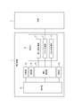
- FIG. 2 is a block diagram including the measurement device of FIG. 1 and a solution.
- FIG. 3 is an enlarged view of a tip portion of a second comparison electrode unit in FIG. 2.
- FIG. 2 is a schematic diagram showing the time dependence of the pH concentration of a solution obtained by the measuring device of FIG. 3 is a flowchart illustrating an example of an operation of the measurement device of FIG.
- FIG. 4 is a schematic diagram illustrating a first modification of the measuring device of FIG. 1. It is a schematic diagram which shows the 2nd modification of the measuring device of FIG. It is a schematic diagram which shows the 3rd modification of the measuring device of FIG. It is a mimetic diagram showing an example of composition of a measuring device concerning a 2nd embodiment. It is a mimetic diagram showing an example of composition of a measuring device concerning a 3rd embodiment.
- FIG. 3 FIG. 6, FIG. 7, FIG. 9, and FIG.
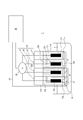
- FIG. 1 is a schematic diagram showing an example of the configuration of the measuring device 1 according to the first embodiment.
- the measurement device 1 according to the first embodiment acquires information on the state of the solution L.
- “information on the state of the solution L” includes a pH concentration, that is, a hydrogen ion concentration.
- the measuring device 1 according to the first embodiment has a plurality of electrode units used for a glass electrode type pH measurement. Referring to FIG. 1, the measuring device 1 has a measuring unit 10 and a protection unit 20 attached to the measuring unit 10.
- the measuring unit 10 outputs a measurement signal associated with the state of the solution L.
- the measurement unit 10 has a first part P1 in a usable state and a second part P2 in a measurement standby state.
- the “usable state” includes the state of the measurement unit 10 that can contribute to the output of a measurement signal associated with the state of the solution L by being in contact with the solution L. More specifically, in the first embodiment, the “usable state” includes the state of the measurement unit 10 that can contribute to the output of a measurement signal based on the glass electrode type pH measurement.
- the “standby state for measurement” includes the state of the measurement unit 10 that is isolated from the solution L by the protection unit 20 and does not contribute to the output of the measurement signal associated with the state of the solution L. More specifically, in the first embodiment, the “standby state of measurement” includes a state of the measurement unit 10 that does not contribute to the output of the measurement signal based on the glass electrode type pH measurement.
- the first portion P1 of the measurement unit 10 has a pair of glass electrode units 11 and a first comparison electrode unit 12.
- the glass electrode unit 11 has a glass thin film 11a that responds to hydrogen ions, an internal liquid 11b having a known pH concentration, an internal electrode 11c for reading out an electric signal, and a support 11d that supports the internal electrode 11c.
- the glass thin film 11a is attached to the tip of the support 11d.
- the internal liquid 11b is filled in the support 11d.
- the internal solution 11b may include any solution such as a phosphate buffer having a pH of 7, for example.
- the internal electrode 11c is immersed in the internal liquid 11b filled inside the support 11d.
- the first comparison electrode section 12 includes a liquid junction section 12a, an internal liquid 12b having a known pH concentration and a small inter-liquid potential, an internal electrode 12c for reading out an electric signal, and a support for supporting the internal electrode 12c. 12d.
- the liquid junction 12a is disposed at the tip of the support 12d and has a plurality of fine holes.
- the internal liquid 12b is filled in the support 12d.
- the internal liquid 12b may include any solution such as, for example, a KCL solution.
- the internal liquid 12b diffuses into the solution L via the liquid junction 12a.
- the internal electrode 12c is immersed in the internal liquid 12b filled inside the support 12d.
- the glass electrode type pH measurement based on the first portion P1 two different types of solutions are arranged inside and outside the support portion 11d with respect to the glass thin film 11a. That is, the internal liquid 11b and the solution L are arranged. At this time, an electromotive force proportional to the difference between the pH concentrations of the internal solution 11b and the solution L is generated on both surfaces of the glass thin film 11a.
- the internal electrode 11c immersed in the internal liquid 11b generates an electromotive force corresponding to the electromotive force generated on both surfaces of the glass thin film 11a.
- the internal electrode 12c immersed in the internal liquid 12b constantly generates a constant electromotive force while being in electrical contact with the solution L as the internal liquid 12b diffuses into the solution L via the liquid junction 12a. generate.
- the internal liquid 12b is gradually reduced from the liquid junction 12a.
- the internal solution 12b gradually decreases as the measurement time elapses with the measurement of the pH concentration of the solution L by the measurement device 1.
- the measurement using the first portion P1 of the measurement unit 10 becomes impossible. Therefore, in the conventional glass electrode type pH measuring device without the second part P2 and the protection unit 20, due to these factors, maintenance work including calibration and replenishment of the internal solution 12b takes, for example, about one to three months. It happened in a short time.
- the measuring device 1 solves such a problem, realizes the measurement of the state of the solution L for a long time, and improves the convenience for the user.
- the measuring device 1 includes the second part P2 of the measuring unit 10 and the protection unit 20.
- the second portion P2 of the measurement section 10 has a pair of glass electrode sections 11 and a second comparison electrode section 13 different from the first comparison electrode section 12 in a usable state.
- the second comparison electrode unit 13 includes a liquid junction 13a, an internal liquid 13b having a known pH concentration and a small inter-liquid potential, an internal electrode 13c for reading out an electric signal, and a support for supporting the internal electrode 13c. 13d.
- the liquid junction 13a is arranged at the tip of the support 13d and has a plurality of fine holes.
- the internal liquid 13b is filled in the support 13d.
- the internal liquid 13b may include an arbitrary solution such as a KCL solution. The diffusion of the internal liquid 13b into the solution L via the liquid junction 13a is suppressed by the protection unit 20.
- the internal electrode 13c is immersed in the internal liquid 13b filled in the support 13d.
- the distance between the internal electrode 11c included in the glass electrode unit 11 and the internal electrode 12c included in the first comparison electrode unit 12 is the same as the distance between the internal electrode 11c and the internal electrode 13c included in the second comparison electrode unit 13. There may be. Thereby, since the distance between the internal electrode 11c of the glass electrode unit 11 and the internal electrode of each comparative electrode unit is constant, the measurement results using the internal electrode 11c and the internal electrode 12c and the internal electrode 11c and the internal electrode 11c The measurement error is reduced from the measurement result when the internal electrode 13c is used.
- FIG. 2 is a block diagram including the measuring device 1 and the solution L of FIG.
- the measurement device 1 includes a voltage detection unit 30 in addition to a measurement unit 10 including a glass electrode unit 11, a first comparison electrode unit 12, and a second comparison electrode unit 13, and a protection unit 20,
- the control unit 40 includes a control unit 40, a communication unit 50, and a storage unit 60.
- Voltage detector 30 includes an arbitrary voltage sensor capable of detecting a voltage.
- the voltage detection unit 30 detects a difference between electromotive forces generated between the internal electrode 11c of the glass electrode unit 11 and the internal electrode 12c of the first comparison electrode unit 12, that is, a voltage.
- the voltage detection unit 30 connects the internal electrode 12c to the internal electrode of the second comparison electrode unit 13 in response to switching from measurement based on the first comparison electrode unit 12 to measurement based on the second comparison electrode unit 13, which will be described later. 13c.
- the control unit 40 includes one or more processors.
- the control unit 40 includes a processor that enables processing related to the measurement device 1.
- the control unit 40 is connected to each component of the measuring device 1 and controls and manages the entire measuring device 1 including each component.
- the control unit 40 acquires information on the state of the solution L based on the measurement signal output from the measurement unit 10. More specifically, the control unit 40 calculates the pH concentration of the solution L based on the voltage signal from the measurement unit 10 obtained via the voltage detection unit 30.
- the communication unit 50 includes an arbitrary communication interface corresponding to an arbitrary communication protocol based on a wired or wireless communication.
- the communication unit 50 may transmit information on the state of the solution L acquired by the control unit 40 to any external device.
- the communication unit 50 may receive a control signal for controlling the electrode heater 23 of the protection unit 20 described below from any external device.
- the storage unit 60 is an arbitrary storage such as a hard disk drive (HDD), a solid state drive (SSD), an electrically erasable programmable read-only memory (EEPROM), a read-only memory (ROM), and a random access memory (RAM).
- the device includes information necessary for realizing the operation of the measuring device 1.
- the storage unit 60 may function as a main storage device, an auxiliary storage device, or a cache memory.
- the storage unit 60 is not limited to the one built in the measuring device 1 and may be an external storage device connected by a digital input / output port such as a USB.
- the storage unit 60 stores, for example, information on the state of the solution L acquired by the control unit 40.
- FIG. 3 is an enlarged view of the tip of the second comparison electrode unit 13 of FIG.
- illustration of the internal liquid 13b and the internal electrode 13c accommodated inside the support portion 13d is omitted.
- the configuration and function of the protection unit 20 will be mainly described with reference to FIG.
- the protection unit 20 has a protection plate 21 that separates the solution L from the second portion P2 of the measurement unit 10. More specifically, the protection plate 21 electrically isolates the solution L from the second comparison electrode unit 13 included in the second portion P2.
- the protection plate 21 may be made of, for example, at least one of a biodegradable resin and an acid-soluble resin including a resin whose molecular weight is controlled such as an acrylic acid type and a phthalic acid type.
- the configuration of the protection plate 21 is not limited to this.
- the protection plate 21 may be made of, for example, any material having neither biodegradability nor acid solubility.
- the protection plate 21 is attached to the distal end surface of the support portion 13d of the second comparison electrode portion 13 of the measurement portion 10 by, for example, bonding with a heat-soluble adhesive 22.
- the heat-soluble adhesive 22 is an arbitrary resin having a melting point higher than the temperature of the solution L to be measured and lower than the temperature when heated by the electrode heater 23 described later.
- the space between the protective plate 21 and the liquid junction 13a of the second comparison electrode 13 is filled with an internal liquid 13e having a known characteristic.
- the “characteristics” of the internal liquid 13e include, for example, a pH concentration.
- the internal solution 13e may be the same solution as the internal solution 13b, a solution having the same pH concentration as the internal solution 13b, and a solution composed of different components, or a solution completely different from the internal solution 13b. It may be.
- the protection unit 20 further includes an electrode heater 23 that heats a portion where the protection plate 21 and the measurement unit 10 are attached.
- the above-mentioned hot-melt adhesive 22 is interposed in the attachment portion between the protection plate 21 and the measurement unit 10, more specifically, in the attachment portion between the protection plate 21 and the support portion 13d of the second comparison electrode unit 13. .
- the electrode heater 23 is arranged in the vicinity of the heat-soluble adhesive 22 and is connected to the control unit 40 via the electric wire 24 as shown in FIG. The electrode heater 23 heats the hot-melt adhesive 22 under the control of the control unit 40.
- FIG. 4 is a schematic diagram showing the time dependence of the pH concentration of the solution L obtained by the measuring device 1 of FIG.
- the vertical axis in FIG. 4 indicates the pH concentration of the solution L.
- the horizontal axis in FIG. 4 indicates the measurement time.
- the dashed line shown in the example of the measurement graph of FIG. 4 indicates the drift of the measured value of the pH concentration of the solution L.
- the measured value of the pH concentration of the solution L obtained by the measuring device 1 drifts in a certain direction as the measuring time elapses.
- the measured value of the pH concentration of the solution L also changes correspondingly.
- the measured value of the pH concentration of the solution L is: It shows a drift such that the measured value decreases at a constant rate.
- the measurement device 1 is appropriately selected by the user so that the user can grasp a measure of the pH concentration of the solution L to some extent and have a measurement range suitable for the pH concentration of the solution L. That is, the measuring device 1 has a predetermined range in which measurement is possible.
- the control unit 40 determines whether or not the measured value of the information on the state of the solution L has exceeded a predetermined range that can be measured by the first part P1 of the measuring unit 10. For example, the measurement value of the information on the state of the solution L exceeds the lower limit of a predetermined range that can be measured by the measurement device 1 at a certain measurement time due to the drift described above.
- the measured value of the information on the state of the solution L is, for example, zero when all of the internal liquid 12b of the first comparison electrode unit 12 flows out to the solution L and the remaining amount of the internal liquid 12b in the first comparison electrode unit 12 becomes zero. Or increase and shake off.
- the measured value of the information on the state of the solution L exceeds the lower limit or the upper limit of a predetermined range that can be measured by the measuring device 1.
- the measurement value of the information on the state of the solution L is, for example, when a foreign substance adheres to the surface of the glass thin film 11a, the specific value determined by the foreign substance exceeds the lower limit or the upper limit of a predetermined range that can be measured by the measuring device 1. Maintain the pH concentration.
- the control unit 40 When the control unit 40 determines that the measured value of the information on the state of the solution L exceeds the predetermined range, the control unit 40 heats the electrode heater 23 and removes the protection plate 21 from the measurement unit 10 by heating the electrode heater 23. At this time, the control unit 40 acquires a measurement signal based on the second portion P2. More specifically, the control unit 40 switches from the measurement using the glass electrode unit 11 and the first comparison electrode unit 12 to the measurement using the glass electrode unit 11 and the second comparison electrode unit 13. The voltage detection unit 30 switches the connection of the first comparison electrode unit 12 to the internal electrode 12c to the connection of the second comparison electrode unit 13 to the internal electrode 13c in response to the switching of the measurement by the control unit 40.
- FIG. 5 is a flowchart showing an example of the operation of the measuring device 1 of FIG. An example of the operation of the measuring device 1 will be mainly described with reference to FIG.
- step S101 the measuring device 1 measures the state of the solution L based on the first portion P1. More specifically, the control unit 40 continuously obtains information on the state of the solution L based on the voltage signal output from the measurement unit 10 using the glass electrode unit 11 and the first comparison electrode unit 12. .
- step S102 the control unit 40 determines whether or not the measured value of the information on the state of the solution L has exceeded a predetermined range that can be measured by the first part P1 of the measuring unit 10.
- the flow proceeds to step S103. If the control unit 40 determines that the measured value of the information on the state of the solution L does not exceed the predetermined range, the flow returns to step S101.
- step S103 the control unit 40 stops the measurement based on the first comparison electrode unit 12, heats the electrode heater 23, and removes the protection plate 21 from the measurement unit 10 by heating the electrode heater 23. More specifically, the control unit 40 dissolves the hot-melt adhesive 22 that bonds the protection plate 21 and the support unit 13d with the electrode heater 23, and detaches the protection plate 21.
- the protective plate 21 is made of an acid-soluble resin and the solution L is acidic
- the thickness of the protective plate 21 depends on the measurement time when the measured value of the pH concentration of the solution L exceeds the lower limit due to drift and the solution. It may be determined by the acid concentration of L.
- the thickness of the protective plate 21 is set so that the protective plate 21 is not completely dissolved by the solution L before the measurement time when the measured value of the pH concentration of the solution L exceeds the lower limit value due to drift. It may be a thickness.
- the detached protective plate 21 is dissolved by the solution L and disappears.
- step S104 the measuring device 1 measures the state of the solution L based on the second portion P2. More specifically, the control unit 40 continuously acquires information on the state of the solution L based on the voltage signal output from the measurement unit 10 using the glass electrode unit 11 and the second comparison electrode unit 13. .
- the state of the solution L can be measured for a long time, and the convenience for the user is improved. More specifically, in addition to the first part P1, the measurement unit 10 has the second part P2 in a measurement standby state, so that the calibration and internal liquid 12b can be stored while the measuring apparatus 1 is kept small. The cycle of maintenance work including replenishment is extended, and long-term measurement becomes possible. Even when the measurement based on the first comparison electrode unit 12 becomes impossible, the measurement can be continued based on the second comparison electrode unit 13, so that the measurement device 1 can be removed into a living body and a process where it is difficult to take out the measurement device 1. Long-term measurement is possible with the measurement device 1 introduced. For example, if the measuring device 1 is used, continuous measurement on a yearly basis is possible.
- the user can use a communication method such as wireless communication, for example, even if the user is not at the site where the measurement device 1 is installed. Information can be obtained.
- FIG. 6 is a schematic diagram showing a first modification of the measuring device 1 of FIG. FIG. 6 shows a state when the measurement unit 10 and the protection unit 20 of the measurement device 1 are viewed from the bottom side.
- the measurement unit 10 has been described as having one glass electrode unit 11 and two comparison electrode units, but is not limited thereto.
- the measurement unit 10 may have three or more comparison electrode units for one glass electrode unit 11.
- the measurement unit 10 includes, for example, a third comparison electrode unit 14 and a fourth comparison electrode unit 15 in addition to the glass electrode unit 11, the first comparison electrode unit 12, and the second comparison electrode unit 13. May be further provided.
- a protection unit 20 similar to the above-described protection unit 20 attached to the second comparison electrode unit 13 may be attached to the third comparison electrode unit 14 and the fourth comparison electrode unit 15. . That is, the first portion P1 of the measurement unit 10 in a usable state has the pair of glass electrode units 11 and the first comparison electrode unit 12 as described above.
- the second portion P ⁇ b> 2 of the measurement unit 10 in the measurement standby state further includes a third comparison electrode unit 14 and a fourth comparison electrode unit 15 in addition to the second comparison electrode unit 13.
- the distance between the internal electrode 11c included in the glass electrode unit 11 and the internal electrode included in each comparative electrode unit may be the same.
- the internal electrodes included in each comparison electrode unit may be arranged concentrically around the internal electrode 11c included in the glass electrode unit 11. Accordingly, since the distance between the internal electrode 11c of the glass electrode unit 11 and the internal electrode of each comparative electrode unit is constant, the inter-electrode distance between the internal electrode 11c and the internal electrode of each comparative electrode unit is reduced. Reduces the measurement error.
- the protection plate 21 is described as being attached to the distal end surface side of the corresponding support portion via the heat-soluble adhesive 22, but the method of attaching the protection plate 21 is not limited to this. .
- the protection plate 21 may be fixed by any method. For example, when it is necessary to fix a plurality of protection plates 21 as shown in FIG. 6, instead of attaching the protection plates 21 to the corresponding support portions, heat-melting is performed on the distal end surface side of the support portion 10a accommodating the respective electrode portions collectively. A plurality of protection plates 21 may be attached via the conductive adhesive 22.
- the protection plate 21 is attached directly to the distal end surface of the corresponding support portion without the hot-melt adhesive 22, instead of being attached to the distal end surface side of the corresponding support portion via the hot-melt adhesive 22. May be. That is, the heat-soluble adhesive 22 is unnecessary.
- the protective plate 21 is made of an arbitrary resin having a melting point higher than the temperature of the solution L to be measured and lower than the temperature when heated by the electrode heater 23. Thereby, the protection plate 21 can be appropriately detached in a predetermined measurement time under the control of the electrode heater 23 by the control unit 40.
- FIG. 7 is a schematic diagram showing a second modification of the measuring device 1 of FIG.
- FIG. 7 shows a state when the measurement unit 10 and the protection unit 20 of the measurement device 1 are viewed from the bottom side.
- the measurement unit 10 is described as having one glass electrode unit 11, but is not limited to this.
- the measurement unit 10 may have two or more glass electrode units.
- the measurement unit 10 may have another pair of glass electrode units 16 and the second comparison electrode unit 13 in addition to the pair of glass electrode units 11 and the first comparison electrode unit 12.
- a protection unit 20 similar to the above-described protection unit 20 attached to the second comparison electrode unit 13 may be attached to the glass electrode unit 16. That is, the first portion P1 of the measurement unit 10 in a usable state has the pair of glass electrode units 11 and the first comparison electrode unit 12 as described above.
- the second portion P ⁇ b> 2 of the measurement unit 10 in a measurement standby state has a pair of glass electrode units 16 and a second comparison electrode unit 13.
- the protection plate 21 suppresses the deterioration of the glass electrode portion 16 in addition to the second comparison electrode portion 13. For example, it is possible to suppress foreign substances from adhering to the surface of the glass thin film of the glass electrode section 16 and to suppress contamination of the glass thin film.
- the distance between the internal electrode 11c included in the glass electrode unit 11 and the internal electrode 12c included in the first comparison electrode unit 12 is equal to the internal electrode included in the glass electrode unit 16 and the internal electrode 13c included in the second comparison electrode unit 13. May be the same as Thus, the distance between the internal electrodes of each pair of glass electrode portions and the internal electrode of the comparison electrode portion is the same for pairs having different electrodes. Therefore, a measurement error is reduced between the measurement results when the internal electrode of each pair of glass electrode portions and the internal electrode of the comparison electrode portion are used.
- FIG. 8 is a schematic view showing a third modification of the measuring device 1 of FIG.
- the protection plate 21 has been described as being individually attached to each electrode unit included in the second portion P2 of the measurement unit 10, but the method of attaching the protection plate 21 is not limited to this.
- the second portion P ⁇ b> 2 of the measurement unit 10 in the measurement standby state includes the pair of glass electrode units 16 and the second comparison electrode unit 13, the pair of glass electrodes
- the protection plate 21 may be attached to the portion 16 and the second comparison electrode portion 13 collectively.
- the protection plate 21 and the second section P ⁇ b> 2 of the measurement section 10 are not included.
- the space between the two portions P2 may be filled with an internal liquid 13e whose properties are known. Thereby, calibration using the glass electrode unit 16 and the second comparison electrode unit 13 is possible until immediately before the control unit 40 detaches the protection plate 21. More specifically, the measuring device 1 measures the internal liquid 13e having a known pH concentration using the glass electrode unit 16 and the second comparison electrode unit 13 before the protective plate 21 is detached. Thereby, the control unit 40 and the user can determine whether or not the known pH concentration and the measured value match. Therefore, the calibration of the measuring device 1 is facilitated.
- the internal liquid 13e is described as an arbitrary solution, but is not limited to this.
- the internal liquid 13e may be any gel.
- the control unit 40 may calculate the measurement lifetime T in advance based on the drift gradient calculated by calibration before the use of the measuring device 1 and the lower limit value of a measurable predetermined range.
- the control unit 40 previously calculates the measured lifetime T based on the initial filling amount of the internal liquid 12b of the first comparison electrode unit 12 and the outflow amount per unit time of the internal liquid 12b flowing out of the liquid junction 12a. May be.
- the control unit 40 may store the calculated measurement life T in the storage unit 60 and compare the usage time of the first part P1 of the measurement unit 10 with the measurement life T calculated in advance. For example, when the control unit 40 determines that the measurement life T has not been reached, the measurement based on the first portion P1 of the measurement unit 10 is continued. For example, when the control unit 40 determines that the measurement life T has been reached, the control unit 40 switches to the measurement based on the second part P2 of the measurement unit 10.
- the control unit 40 measures the remaining amount of the internal solution 12b in real time based on, for example, an arbitrary sensor installed inside the support unit 12d, and determines whether the remaining amount of the internal solution 12b has become zero. You may. For example, when the control unit 40 determines that the remaining amount of the internal liquid 12b is not zero, the control unit 40 continues the measurement based on the first portion P1 of the measurement unit 10. For example, when the control unit 40 determines that the remaining amount of the internal liquid 12b has become zero, the control unit 40 switches to measurement based on the second part P2 of the measurement unit 10.
- the protection plate 21 is detached by controlling the electrode heater 23, but the method of removing the protection plate 21 is not limited to this.
- the protection unit 20 may not have the electrode heater 23.
- the protection plate 21 is made of, for example, a biodegradable resin or an acid-soluble resin, and is gradually decomposed or dissolved by the solution L.
- the protective plate 21 is formed, for example, to a thickness such that the time required for the protective plate 21 to completely dissolve or dissolve substantially coincides with the measured lifetime T.
- the electrode heater 23 is not required, and thus, for example, consumption of a battery attached to the measuring device 1 as a power source is suppressed. Since the space for mounting the electrode heater 23 is omitted, the measuring device 1 is downsized.
- the measuring device 1 may further include a temperature sensor that measures the temperature of the solution L and is installed at an arbitrary position such as an outer wall of each support. Thereby, the control unit 40 can correct the measurement value of the information on the state of the solution L based on the measured temperature of the solution L.
- a temperature sensor may be provided between the protection plate 21 and the second portion P2. Thereby, the temperature sensor is isolated from the solution L during the measurement based on the first part P1. Therefore, the deterioration of the temperature sensor is suppressed, and when the measurement based on the second portion P2 starts, the temperature sensor can detect the temperature in an unused state.
- FIG. 9 is a schematic diagram illustrating an example of a configuration of the measuring device 1 according to the second embodiment.
- the configuration and functions of the measuring device 1 according to the second embodiment will be mainly described with reference to FIG.
- the information on the state of the solution L includes the pH concentration
- the measuring unit 10 has been described as having each electrode unit used for the glass electrode type pH measurement, but is not limited thereto.
- the information on the state of the solution L includes the ion concentration
- the measuring unit 10 may include a first ISFET 71 and a second ISFET 72.
- the configuration other than the measurement unit 10 of the measurement device 1 according to the second embodiment is the same as that of the first embodiment, and the above description in the first embodiment is applied to the configuration as it is.
- the same components as those in the first embodiment are denoted by the same reference numerals, and description thereof will be omitted. The differences from the first embodiment will be mainly described.
- the measurement unit 10 has a first ISFET 71 and a second ISFET 72.
- the first ISFET 71 has a measurement electrode including a source electrode 71a and a drain electrode 71b, and a comparison electrode 71c.
- the first ISFET 71 has an ion-sensitive film 71d disposed over the source electrode 71a and the drain electrode 71b.
- the second ISFET 72 has a measurement electrode including a source electrode 72a and a drain electrode 72b, and a comparison electrode 72c.
- the second ISFET 72 has an ion-sensitive film 72d disposed over the source electrode 72a and the drain electrode 72b.
- the first part P1 of the measurement unit 10 has the first ISFET 71.
- the second part P2 of the measurement unit 10 has a second ISFET 72.
- the protection part 20 is not attached to the first ISFET 71, and the ion-sensitive film 71 d of the first ISFET 71 comes into contact with the solution L.
- the protection part 20 is attached to the second ISFET 72, and the ion-sensitive film 72 d of the second ISFET 72 is isolated from the solution L. Therefore, in the ion-sensitive film 72 d of the second ISFET 72, the protection unit 20 suppresses deterioration including adhesion of foreign matter, deterioration, and scraping.
- the measurement unit 10 of the measurement device 1 according to the second embodiment may further include a plurality of ISFETs having the same configuration as the second ISFET 72 to which the protection unit 20 is attached.
- the measuring apparatus 1 according to the second embodiment as described above has the same effects as the first embodiment.
- the measuring unit 10 is configured by a small ISFET. Therefore, even if the number of components of the second portion P2 is made larger than that of the first embodiment, the measuring device 1 is kept small.
- the measuring device 1 according to the second embodiment can extend the maintenance work cycle even in a state where the measuring device is maintained in a small size, and enables long-term measurement.
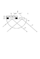
- FIG. 10 is a schematic diagram illustrating an example of the configuration of the measuring device 1 according to the third embodiment.
- the configuration and functions of the measuring device 1 according to the third embodiment will be mainly described with reference to FIG.
- the information on the state of the solution L includes an ion concentration or a chemical component composition amount
- the measuring unit 10 includes a first metal thin film 81, a second metal thin film 82, It may include a prism substrate 83 and a photodetector (not shown).
- the configuration of the measuring device 1 according to the third embodiment other than the measuring unit 10 is the same as that of the first embodiment, and the description in the first embodiment is applied to the configuration as it is.
- the same components as those in the first embodiment are denoted by the same reference numerals, and description thereof will be omitted. The differences from the first embodiment will be mainly described.
- the measurement unit 10 includes a first metal thin film 81, a second metal thin film 82, a prism substrate 83, and a photodetector (not shown).
- the first metal thin film 81 or the second metal thin film 82 is irradiated with the measurement light L1 via the prism substrate 83.
- the control unit 40 obtains the light absorption spectrum of the solution L with which the first metal thin film 81 contacts by detecting the measurement light L1 reflected on the surface of the first metal thin film 81 by a photodetector.
- the control unit 40 analyzes the ion concentration or the chemical composition of each component in the solution L based on the acquired light absorption spectrum.
- the first portion P1 of the measuring unit 10 has the first metal thin film 81.
- the second portion P2 of the measurement unit 10 has a second metal thin film 82.
- the protection part 20 is not attached to the first metal thin film 81, and the first metal thin film 81 comes into contact with the solution L.
- the protection part 20 is attached to the second metal thin film 82, and the second metal thin film 82 is isolated from the solution L. Therefore, in the second metal thin film 82, the protection part 20 suppresses deterioration including adhesion of foreign matter, alteration, and scraping.
- the measurement unit 10 of the measurement device 1 according to the third embodiment may further include a plurality of metal thin films having the same configuration as the second metal thin film 82 to which the protection unit 20 is attached.
- the measuring device 1 according to the third embodiment as described above has the same effects as the first embodiment.
- the measuring device 1 according to the third embodiment unlike the first and second embodiments, there is no drift of the measurement signal. Therefore, the measuring device 1 can measure the state of the solution L for a long period of time as long as the metal thin film is not deteriorated by factors including adhesion of foreign matter, deterioration, and shaving. Even if the metal thin film is deteriorated, the measurement unit 10 of the measurement device 1 has the second portion P2, so that the measurement device 1 can extend the cycle of the maintenance work, and can perform long-term measurement.
- the shape, arrangement, orientation, number, and the like of each of the components described above are not limited to the contents described above and illustrated in the drawings.
- the shape, arrangement, orientation, number, and the like of each component may be arbitrarily configured as long as the function can be realized.
- each step of the measurement method using the above-described measuring device 1 can be rearranged so as not to be logically inconsistent, and a plurality of steps can be combined into one or divided. It is possible.
Landscapes
- Life Sciences & Earth Sciences (AREA)
- Health & Medical Sciences (AREA)
- Chemical & Material Sciences (AREA)
- Physics & Mathematics (AREA)
- General Health & Medical Sciences (AREA)
- Pathology (AREA)
- Analytical Chemistry (AREA)
- Biochemistry (AREA)
- General Physics & Mathematics (AREA)
- Immunology (AREA)
- Chemical Kinetics & Catalysis (AREA)
- Molecular Biology (AREA)
- Electrochemistry (AREA)
- Engineering & Computer Science (AREA)
- Microelectronics & Electronic Packaging (AREA)
- Optics & Photonics (AREA)
- Biophysics (AREA)
- Biomedical Technology (AREA)
- Heart & Thoracic Surgery (AREA)
- Medical Informatics (AREA)
- Surgery (AREA)
- Animal Behavior & Ethology (AREA)
- Public Health (AREA)
- Veterinary Medicine (AREA)
- Computer Hardware Design (AREA)
- General Chemical & Material Sciences (AREA)
- Mathematical Physics (AREA)
- Investigating Or Analyzing Materials By The Use Of Electric Means (AREA)
Abstract
本開示に係る測定装置1は、溶液Lの状態を測定する測定装置1であって、溶液Lの状態に関連付けられた測定信号を出力する測定部10と、測定部10に取り付けられている保護部20と、測定部10から出力される測定信号に基づいて、溶液Lの状態に関する情報を取得する制御部40と、を備え、測定部10は、溶液Lと接触することで測定信号の出力に寄与する使用可能状態にある第1部分P1と、保護部20によって溶液Lと隔離され、測定の待機状態にある第2部分P2と、を有する。
Description
本出願は、2018年9月27日に日本国に特許出願された特願2018-182466号の優先権を主張するものであり、当該出願の開示全体を、ここに参照のために取り込む。
本開示は、溶液の状態を測定する測定装置に関する。
溶液中に含まれる水素イオン等の任意のイオンの濃度を測定する技術が従来から知られている。
例えば、特許文献1には、比較部の安定性に優れるとともに、化学的及び物理的耐久性にも優れることで、測定結果の再現性及び安定性が良好な、小型化及び固体化可能なイオン感応型電界効果トランジスタ(Ion Sensitive Field Effect Transistor (ISFET))型のイオンセンサが開示されている。
しかしながら、測定部において溶液と接触している部分が、異物の付着、変質、及び削れ等を含む原因によって使用と共に劣化し、測定部から正確な測定信号が出力されなくなるといった問題があった。特許文献1に記載のイオンセンサのような場合、例えば、溶液と接触することでイオン感応膜が次第に劣化する。このとき、ユーザは、新たなイオンセンサに短期で交換する必要があり、利便性が低かった。
本開示は、長期にわたって溶液の状態を測定可能であり、ユーザの利便性が向上する測定装置を提供することを目的とする。
幾つかの実施形態に係る測定装置は、溶液の状態を測定する測定装置であって、前記溶液の状態に関連付けられた測定信号を出力する測定部と、前記測定部に取り付けられている保護部と、前記測定部から出力される前記測定信号に基づいて、前記溶液の状態に関する情報を取得する制御部と、を備え、前記測定部は、前記溶液と接触することで前記測定信号の出力に寄与する使用可能状態にある第1部分と、前記保護部によって前記溶液と隔離され、測定の待機状態にある第2部分と、を有する。これにより、長期にわたって溶液の状態を測定可能であり、ユーザの利便性が向上する。より具体的には、測定の待機状態にある第2部分を測定部が有することで、校正及び内部液の補充等を含むメンテナンス作業の周期が延長され、長期間の測定が可能になる。例えば、測定装置を用いれば、年単位での連続測定が可能である。
一実施形態において、前記保護部は、前記測定部の前記第2部分と前記溶液とを隔離する保護板を有し、前記保護板は、生分解性樹脂及び酸溶解性樹脂の少なくとも一方によって構成されてもよい。これにより、測定部の第2部分は、溶液と接触しないので、測定部の第2部分の劣化が抑制される。測定部の第2部分は、第1部分による測定が継続されている間も、未使用の状態を維持可能である。生分解性樹脂及び酸溶解性樹脂の少なくとも一方によって保護板が構成されることで、保護板が測定部から脱離した場合であっても、溶液によって分解又は溶解する。したがって、保護板が溶液中に異物として残存することを防止できる。
一実施形態において、前記保護部は、前記保護板と前記測定部との取付部分を加熱するヒータをさらに有してもよい。これにより、保護板と測定部との取付部分の状態をヒータによる加熱で制御可能である。
一実施形態において、前記取付部分は、前記溶液の温度よりも高く、かつ前記ヒータによって加熱される際の温度よりも低い融点を有する熱溶解性接着剤を含み、前記保護板は、前記熱溶解性接着剤による接着により前記測定部に取り付けられていてもよい。これにより、ヒータの加熱によって取付部分に含まれる熱溶解性接着剤が溶解することで、保護板が測定部から脱離する。したがって、測定部の第2部分を測定の待機状態から使用可能状態へと切り替える制御がヒータの制御によって可能となり、当該切り替え制御が容易になる。
一実施形態において、前記制御部は、前記測定部の前記第1部分によって測定可能な所定の範囲を前記溶液の状態に関する情報の測定値が超えたと判定すると、前記ヒータの加熱によって前記保護板を前記測定部から取り外し、前記第2部分に基づいて前記測定信号を取得してもよい。これにより、測定部の第1部分に基づく測定が不可能となった場合であっても、測定部の第2部分に基づく測定に切り替えることが可能である。したがって、長期にわたって溶液の状態を測定可能であり、ユーザの利便性が向上する。
一実施形態において、前記保護板と前記測定部の前記第2部分との間に、特性が既知である内部液又はゲルが充填されていてもよい。これにより、制御部が保護板を脱離させる直前まで測定部の第2部分を用いた測定装置の校正が可能である。
一実施形態において、前記溶液の状態に関する情報は、pH濃度を含み、前記測定部は、ガラス電極型pH測定に用いられる、1つのガラス電極部と、第1比較電極部と、第2比較電極部とを有し、前記第1部分は、一対の前記ガラス電極部と前記第1比較電極部とを有し、前記第2部分は、前記第2比較電極部を有してもよい。これにより、従来のガラス電極型pH測定装置を用いた場合でも、校正及び内部液の補充等を含むメンテナンス作業の周期が延長され、長期間の測定が可能になる。
一実施形態において、前記ガラス電極部に含まれる内部電極と前記第1比較電極部に含まれる内部電極との距離は、前記ガラス電極部に含まれる前記内部電極と前記第2比較電極部に含まれる内部電極との距離と同一であってもよい。これにより、ガラス電極部の内部電極と各比較電極部の内部電極との電極間距離が一定であるため、各比較電極部の内部電極を用いた場合の測定結果の間で測定誤差が低減する。
一実施形態において、前記溶液の状態に関する情報は、イオン濃度を含み、前記測定部は、第1イオン感応型電界効果トランジスタと、第2イオン感応型電界効果トランジスタとを有し、前記第1部分は、前記第1イオン感応型電界効果トランジスタを有し、前記第2部分は、前記第2イオン感応型電界効果トランジスタを有してもよい。これにより、従来のイオン感応型電界効果トランジスタ(ISFET)型測定装置を用いた場合でも、メンテナンス作業の周期が延長され、長期間の測定が可能になる。測定部が小型のISFETによって構成されることで、測定装置1が小型に維持される。
本開示によれば、長期にわたって溶液の状態を測定可能であり、ユーザの利便性が向上する測定装置を提供可能である。
以下では、添付図面を参照しながら本開示の一実施形態について主に説明する。以下の図面では、説明の簡便のために、所定の構成部の図示を適宜省略する。例えば、図3、図6、図7、図9、及び図10において後述する溶液Lの図示は省略されている。
(第1実施形態)
図1乃至図8を参照しながら、第1実施形態に係る測定装置1の構成及び機能について主に説明する。
図1乃至図8を参照しながら、第1実施形態に係る測定装置1の構成及び機能について主に説明する。
図1は、第1実施形態に係る測定装置1の構成の一例を示す模式図である。第1実施形態に係る測定装置1は、溶液Lの状態に関する情報を取得する。第1実施形態において、「溶液Lの状態に関する情報」とは、pH濃度、すなわち水素イオン濃度を含む。第1実施形態に係る測定装置1は、ガラス電極型pH測定に用いられる複数の電極部を有する。図1を参照すると、測定装置1は、測定部10と、測定部10に取り付けられている保護部20とを有する。
測定部10は、溶液Lの状態に関連付けられた測定信号を出力する。測定部10は、使用可能状態にある第1部分P1と、測定の待機状態にある第2部分P2とを有する。「使用可能状態」とは、溶液Lと接触することで、溶液Lの状態に関連付けられた測定信号の出力に寄与することが可能な測定部10の状態を含む。より具体的には、第1実施形態において「使用可能状態」とは、ガラス電極型pH測定に基づく測定信号の出力に寄与することが可能な測定部10の状態を含む。「測定の待機状態」とは、保護部20によって溶液Lと隔離され、溶液Lの状態に関連付けられた測定信号の出力に寄与しない測定部10の状態を含む。より具体的には、第1実施形態において「測定の待機状態」とは、ガラス電極型pH測定に基づく測定信号の出力に寄与しない測定部10の状態を含む。
測定部10の第1部分P1は、一対のガラス電極部11と第1比較電極部12とを有する。ガラス電極部11は、水素イオンに応答するガラス薄膜11aと、pH濃度が既知の内部液11bと、電気信号を読み出すための内部電極11cと、内部電極11cを支持する支持部11dとを有する。ガラス薄膜11aは、支持部11dの先端に取り付けられている。内部液11bは、支持部11dの内部に充填されている。内部液11bは、例えばpH7のリン酸緩衝液等の任意の溶液を含んでもよい。内部電極11cは、支持部11dの内部に充填された内部液11bに浸っている。
第1比較電極部12は、液絡部12aと、pH濃度が既知であり、かつ液間電位が小さい内部液12bと、電気信号を読み出すための内部電極12cと、内部電極12cを支持する支持部12dとを有する。液絡部12aは、支持部12dの先端に配置され、複数の微細な孔を有する。内部液12bは、支持部12dの内部に充填されている。内部液12bは、例えばKCL溶液等の任意の溶液を含んでもよい。内部液12bは、液絡部12aを介して溶液L中に拡散する。内部電極12cは、支持部12dの内部に充填された内部液12bに浸っている。
第1部分P1に基づくガラス電極型pH測定では、ガラス薄膜11aに対して支持部11dの内側及び外側にそれぞれ異なった2種類の溶液が配置されている。すなわち、内部液11bと溶液Lとが配置されている。このとき、内部液11b及び溶液LのpH濃度の差に比例した起電力がガラス薄膜11aの両面に発生する。内部液11bに浸っている内部電極11cは、ガラス薄膜11aの両面に発生する起電力に対応する起電力を発生させる。一方で、内部液12bに浸っている内部電極12cは、液絡部12aを介した溶液Lへの内部液12bの拡散に伴って、溶液Lと電気的に接触しつつ常に一定の起電力を発生させる。
以上のように、測定部10の第1部分P1では、第1比較電極部12の内部電極12cと溶液Lとの電気的接続を維持するために、液絡部12aより内部液12bが少量ずつ拡散される。したがって、内部液12bは、測定装置1による溶液LのpH濃度の測定に伴って、測定時間の経過と共に次第に減少する。内部液12bが空になると、測定部10の第1部分P1を用いた測定が不可能となる。したがって、第2部分P2及び保護部20を有さない従来のガラス電極型pH測定装置では、これらの要因により、校正及び内部液12bの補充等を含むメンテナンス作業が、例えば1~3ヶ月程度の短期間で発生していた。内部液12bの量を増やしてメンテナンス作業の周期を延長することも考えられるが、この場合、内部液12bを収容する支持部12dが大型化し、結果としてガラス電極型pH測定装置全体が大型化する。以上により、従来技術では、ガラス電極型pH測定装置を小型に維持したまま、ガラス電極型pH測定装置による長期の測定が困難であり、ユーザの利便性が低かった。
第1実施形態に係る測定装置1は、このような課題を解決して、溶液Lの状態の測定を長期にわたって実現し、ユーザの利便性を向上させる。このために、測定装置1は、測定部10の第2部分P2と、保護部20とを有する。
測定部10の第2部分P2は、使用可能状態にある一対のガラス電極部11と第1比較電極部12とは異なる第2比較電極部13を有する。第2比較電極部13は、液絡部13aと、pH濃度が既知であり、かつ液間電位が小さい内部液13bと、電気信号を読み出すための内部電極13cと、内部電極13cを支持する支持部13dとを有する。液絡部13aは、支持部13dの先端に配置され、複数の微細な孔を有する。内部液13bは、支持部13dの内部に充填されている。内部液13bは、例えばKCL溶液等の任意の溶液を含んでもよい。液絡部13aを介した内部液13bの溶液Lへの拡散は、保護部20によって抑制されている。内部電極13cは、支持部13dの内部に充填された内部液13bに浸っている。
ガラス電極部11に含まれる内部電極11cと第1比較電極部12に含まれる内部電極12cとの距離は、内部電極11cと第2比較電極部13に含まれる内部電極13cとの距離と同一であってもよい。これにより、ガラス電極部11の内部電極11cと各比較電極部の内部電極との電極間距離が一定であるため、内部電極11c及び内部電極12cを用いた場合の測定結果と、内部電極11c及び内部電極13cを用いた場合の測定結果との間で測定誤差が低減する。
図2は、図1の測定装置1と溶液Lとを含むブロック図である。図2を参照すると、測定装置1は、ガラス電極部11、第1比較電極部12、及び第2比較電極部13を含む測定部10、並びに保護部20に加えて、電圧検出部30と、制御部40と、通信部50と、記憶部60とを有する。
電圧検出部30は、電圧を検出可能な任意の電圧センサを含む。電圧検出部30は、ガラス電極部11の内部電極11cと第1比較電極部12の内部電極12cとに発生する起電力の差、すなわち電圧を検出する。電圧検出部30は、後述する第1比較電極部12に基づく測定から第2比較電極部13に基づく測定への切り替えに応じて、内部電極12cとの接続を第2比較電極部13の内部電極13cとの接続に切り替える。
制御部40は、1つ以上のプロセッサを含む。例えば、制御部40は、測定装置1に関する処理を可能にするプロセッサを含む。制御部40は、測定装置1を構成する各構成部に接続され、各構成部をはじめとして測定装置1全体を制御及び管理する。制御部40は、測定部10から出力される測定信号に基づいて、溶液Lの状態に関する情報を取得する。より具体的には、制御部40は、電圧検出部30を介して取得した測定部10からの電圧信号に基づいて溶液LのpH濃度を算出する。
通信部50は、有線又は無線に基づく任意の通信プロトコルに対応した任意の通信インタフェースを含む。通信部50は、制御部40によって取得された溶液Lの状態に関する情報を任意の外部装置に送信してもよい。通信部50は、後述する保護部20の電極ヒータ23を制御する制御信号を任意の外部装置から受信してもよい。
記憶部60は、HDD(Hard Disk Drive)、SSD(Solid State Drive)、EEPROM(Electrically Erasable Programmable Read-Only Memory)、ROM(Read-Only Memory)、及びRAM(Random Access Memory)等の任意の記憶装置を含み、測定装置1の動作を実現するために必要な情報を記憶する。記憶部60は、主記憶装置、補助記憶装置、又はキャッシュメモリとして機能してもよい。記憶部60は、測定装置1に内蔵されているものに限定されず、USB等のデジタル入出力ポート等によって接続されている外付け型の記憶装置であってもよい。記憶部60は、例えば、制御部40によって取得された溶液Lの状態に関する情報を記憶する。
図3は、図2の第2比較電極部13の先端部の拡大図である。図3では、支持部13dの内部に収容される内部液13b及び内部電極13cの図示は省略されている。図3を参照しながら、保護部20の構成及び機能について主に説明する。
保護部20は、測定部10の第2部分P2と溶液Lとを隔離する保護板21を有する。より具体的には、保護板21は、第2部分P2に含まれる第2比較電極部13と溶液Lとを電気的に隔離する。保護板21は、例えば、生分解性樹脂、並びにアクリル酸系及びフタル酸系等の分子量を制御した樹脂を含む酸溶解性樹脂の少なくとも一方によって構成されてもよい。保護板21の構成はこれに限定されない。保護板21は、例えば、生分解性及び酸溶解性のいずれも有さない任意の材料によって構成されてもよい。
保護板21は、例えば、測定部10の第2比較電極部13の支持部13dの先端面側に、熱溶解性接着剤22による接着により取り付けられている。熱溶解性接着剤22は、測定対象となる溶液Lの温度よりも高く、かつ後述する電極ヒータ23によって加熱される際の温度よりも低い融点を有する任意の樹脂である。
保護板21と第2比較電極部13の液絡部13aとの間には、特性が既知である内部液13eが充填されている。内部液13eの「特性」とは、例えばpH濃度を含む。内部液13eは、内部液13bと同一の溶液であってもよいし、内部液13bとpH濃度が同一で異なる成分により構成される溶液であってもよいし、内部液13bとは全く異なる溶液であってもよい。
このように、液絡部13aの外側が内部液13e及び保護板21によって保護されていることで、内部液13bの溶液Lへの拡散が抑制される。内部液13e及び保護板21によって、内部電極13cの劣化が抑制され、第2比較電極部13が溶液Lと接触する前の未使用の状態に第2比較電極部13が維持される。
保護部20は、保護板21と測定部10との取付部分を加熱する電極ヒータ23をさらに有する。保護板21と測定部10との取付部分、より具体的には、保護板21と第2比較電極部13の支持部13dとの取付部分には、上述した熱溶解性接着剤22が介在する。電極ヒータ23は、熱溶解性接着剤22の近傍に配置され、図1に示すとおり、通電線24を介して制御部40と接続されている。電極ヒータ23は、制御部40による制御に基づいて熱溶解性接着剤22を加熱する。
図4は、図1の測定装置1によって得られる溶液LのpH濃度の時間依存性を示す模式図である。図4の縦軸は、溶液LのpH濃度を示す。図4の横軸は、測定時間を示す。図4の測定グラフの一例において示す破線は、溶液LのpH濃度の測定値のドリフトを示す。
図4を参照すると、測定装置1によって得られる溶液LのpH濃度の測定値は、測定時間が経過するに従って一定の方向にドリフトする。溶液Lの実際のpH濃度が変化すると溶液LのpH濃度の測定値も対応して変化するが、溶液Lの実際のpH濃度が一定であっても、溶液LのpH濃度の測定値は、測定値が一定の割合で減少するようなドリフトを示す。測定装置1は、溶液LのpH濃度の目安をユーザがある程度把握して、溶液LのpH濃度に適合する測定範囲を有するようにユーザによって適切に選択される。すなわち、測定装置1は、測定可能な所定の範囲を有する。
制御部40は、測定部10の第1部分P1によって測定可能な所定の範囲を溶液Lの状態に関する情報の測定値が超えたか否かを判定する。例えば、溶液Lの状態に関する情報の測定値は、上述したドリフトによって、測定装置1が測定可能な所定の範囲の下限値をある測定時間において超える。溶液Lの状態に関する情報の測定値は、例えば、第1比較電極部12の内部液12bが全て溶液Lに流出し、第1比較電極部12における内部液12bの残量がゼロになると、ゼロの値をとるか、又は増大して振り切る。このとき、溶液Lの状態に関する情報の測定値は、測定装置1が測定可能な所定の範囲の下限値又は上限値を超える。溶液Lの状態に関する情報の測定値は、例えば、ガラス薄膜11aの表面に異物が付着すると、測定装置1が測定可能な所定の範囲の下限値又は上限値を超えて、当該異物によって定まる特定のpH濃度を維持する。
制御部40は、所定の範囲を溶液Lの状態に関する情報の測定値が超えたと判定すると、電極ヒータ23を加熱し、電極ヒータ23の加熱によって保護板21を測定部10から取り外す。このとき、制御部40は、第2部分P2に基づいて測定信号を取得する。より具体的には、制御部40は、ガラス電極部11及び第1比較電極部12を用いた測定から、ガラス電極部11及び第2比較電極部13を用いた測定に切り替える。電圧検出部30は、このような制御部40による測定の切り替えに応じて、第1比較電極部12の内部電極12cとの接続を第2比較電極部13の内部電極13cとの接続に切り替える。
図5は、図1の測定装置1の動作の一例を示すフローチャートである。図5を参照しながら、測定装置1の動作の一例について主に説明する。
ステップS101では、測定装置1は、第1部分P1に基づいて溶液Lの状態を測定する。より具体的には、制御部40は、ガラス電極部11と第1比較電極部12とを用いて測定部10から出力された電圧信号に基づき、溶液Lの状態に関する情報を連続的に取得する。
ステップS102では、制御部40は、測定部10の第1部分P1によって測定可能な所定の範囲を溶液Lの状態に関する情報の測定値が超えたか否かを判定する。所定の範囲を溶液Lの状態に関する情報の測定値が超えたと制御部40が判定すると、フローはステップS103に進む。所定の範囲を溶液Lの状態に関する情報の測定値が超えていないと制御部40が判定すると、フローはステップS101に戻る。
ステップS103では、制御部40は、第1比較電極部12に基づく測定を停止して、電極ヒータ23を加熱し、電極ヒータ23の加熱によって保護板21を測定部10から取り外す。より具体的には、制御部40は、保護板21と支持部13dとを接着している熱溶解性接着剤22を電極ヒータ23で溶解し、保護板21を脱離させる。保護板21が酸溶解性樹脂によって構成され、かつ溶液Lが酸性である場合、保護板21の厚さは、溶液LのpH濃度の測定値がドリフトにより下限値を超えるときの測定時間と溶液Lの酸濃度とによって、定められてもよい。より具体的には、保護板21の厚さは、溶液LのpH濃度の測定値がドリフトにより下限値を超えるときの測定時間よりも前に保護板21が溶液Lによって完全に溶解しないような厚さであってもよい。脱離した保護板21は、溶液Lによって溶解し、消滅する。
ステップS104では、測定装置1は、第2部分P2に基づいて溶液Lの状態を測定する。より具体的には、制御部40は、ガラス電極部11と第2比較電極部13とを用いて測定部10から出力された電圧信号に基づき、溶液Lの状態に関する情報を連続的に取得する。
以上のような第1実施形態に係る測定装置1によれば、長期にわたって溶液Lの状態を測定可能であり、ユーザの利便性が向上する。より具体的には、第1部分P1に加えて、測定の待機状態にある第2部分P2を測定部10が有することで、測定装置1が小型に維持されたまま、校正及び内部液12bの補充等を含むメンテナンス作業の周期が延長され、長期間の測定が可能になる。第1比較電極部12に基づく測定が不可能になった場合であっても、第2比較電極部13に基づいて測定を継続できるので、測定装置1の取り出しが困難な生体内及びプロセス内へ測定装置1を導入したまま、長期間の測定が可能である。例えば、測定装置1を用いれば、年単位での連続測定が可能である。
通信部50により溶液Lの状態に関する情報を任意の外部装置に送信することで、ユーザは、例えば無線通信等の通信方法により測定装置1が設置された現場にいなくても溶液Lの状態に関する情報を取得することができる。
以下では、図6乃至図8を用いて、第1実施形態に係る測定装置1の変形例について主に説明する。
図6は、図1の測定装置1の第1変形例を示す模式図である。図6は、測定装置1の測定部10及び保護部20を底面側から見たときの様子を示す。
第1実施形態では、測定部10は、1つのガラス電極部11と、2つの比較電極部とを有するとして説明したが、これに限定されない。測定部10は、1つのガラス電極部11に対して、3つ以上の比較電極部を有してもよい。図6を参照すると、測定部10は、ガラス電極部11、第1比較電極部12、及び第2比較電極部13に加えて、例えば第3比較電極部14と、第4比較電極部15とをさらに備えてもよい。
このとき、第2比較電極部13に対して取り付けられている上述した保護部20と同様の保護部20が、第3比較電極部14及び第4比較電極部15にも取り付けられていてもよい。すなわち、使用可能状態にある測定部10の第1部分P1は、上記と同様に一対のガラス電極部11と第1比較電極部12とを有する。測定の待機状態にある測定部10の第2部分P2は、第2比較電極部13に加えて、第3比較電極部14及び第4比較電極部15をさらに有する。
ガラス電極部11に含まれる内部電極11cと各比較電極部に含まれる内部電極との距離は、互いに同一であってもよい。例えば、各比較電極部に含まれる内部電極は、ガラス電極部11に含まれる内部電極11cを中心とする同心円状に配置されていてもよい。これにより、ガラス電極部11の内部電極11cと各比較電極部の内部電極との電極間距離が一定であるため、内部電極11c及び各比較電極部の内部電極を用いた場合の測定結果の間で測定誤差が低減する。
上記実施形態では、保護板21は、対応する支持部の先端面側に、熱溶解性接着剤22を介して取り付けられているとして説明したが、保護板21の取付方法は、これに限定されない。保護板21は、任意の方法で固定されてもよい。例えば、図6のように複数の保護板21を固定する必要がある場合、対応する支持部ごとに取り付けるのではなく、各電極部をまとめて収容する支持部10aの先端面側に、熱溶解性接着剤22を介して複数の保護板21が取り付けられていてもよい。
保護板21は、熱溶解性接着剤22を介して対応する支持部の先端面側に取り付けられる代わりに、熱溶解性接着剤22を介さずに、対応する支持部の先端面に直接取り付けられていてもよい。すなわち、熱溶解性接着剤22は不要である。このとき、保護板21は、測定対象となる溶液Lの温度よりも高く、かつ電極ヒータ23によって加熱される際の温度よりも低い融点を有する任意の樹脂により構成される。これにより、保護板21は、制御部40による電極ヒータ23の制御によって、所定の測定時間において適切に脱離可能である。
図7は、図1の測定装置1の第2変形例を示す模式図である。図7は、測定装置1の測定部10及び保護部20を底面側から見たときの様子を示す。
上記では、測定部10は、1つのガラス電極部11を有するとして説明したが、これに限定されない。測定部10は、ガラス電極部を2つ以上有してもよい。例えば、図7に示すとおり、測定部10は、一対のガラス電極部11及び第1比較電極部12に加えて、他の一対のガラス電極部16及び第2比較電極部13を有してもよい。このとき、第2比較電極部13に対して取り付けられている上述した保護部20と同様の保護部20が、ガラス電極部16にも取り付けられていてもよい。すなわち、使用可能状態にある測定部10の第1部分P1は、上記と同様に一対のガラス電極部11と第1比較電極部12とを有する。測定の待機状態にある測定部10の第2部分P2は、一対のガラス電極部16と第2比較電極部13とを有する。以上により、保護板21によって、第2比較電極部13に加えてガラス電極部16の劣化が抑制される。例えば、ガラス電極部16のガラス薄膜の表面に異物が付着することを抑制し、ガラス薄膜の汚染が抑制可能である。
ガラス電極部11に含まれる内部電極11cと第1比較電極部12に含まれる内部電極12cとの距離は、ガラス電極部16に含まれる内部電極と第2比較電極部13に含まれる内部電極13cとの距離と同一であってもよい。これにより、各一対のガラス電極部の内部電極と比較電極部の内部電極との電極間距離が異なる対に対して同一である。したがって、各一対のガラス電極部の内部電極と比較電極部の内部電極とを用いた場合の測定結果の間で測定誤差が低減する。
図8は、図1の測定装置1の第3変形例を示す模式図である。
上記では、保護板21は、測定部10の第2部分P2に含まれる各電極部に対して個別に取り付けられるとして説明したが、保護板21の取り付け方法はこれに限定されない。例えば、図8に示すとおり、図7同様に、測定の待機状態にある測定部10の第2部分P2が一対のガラス電極部16と第2比較電極部13とを有する場合、一対のガラス電極部16及び第2比較電極部13にまとめて保護板21が取り付けられていてもよい。
図7及び図8に示すように、測定部10の第2部分P2において、一対のガラス電極部16及び第2比較電極部13が含まれるような場合でも、保護板21と測定部10の第2部分P2との間に、特性が既知である内部液13eが充填されていてもよい。これにより、制御部40が保護板21を脱離させる直前までガラス電極部16及び第2比較電極部13を用いた校正が可能である。より具体的には、測定装置1は、保護板21が脱離する前に、ガラス電極部16と第2比較電極部13とを用いてpH濃度が既知の内部液13eを測定する。これにより、制御部40及びユーザは、既知のpH濃度と測定値とが一致するか否かを判定可能である。したがって、測定装置1の校正が容易になる。
上記では、内部液13eは、任意の溶液であるとして説明したが、これに限定されない。内部液13eは、任意のゲルであってもよい。
上記では、測定部10の第1部分P1によって測定可能な所定の範囲を溶液Lの状態に関する情報の測定値が超えたか否かを制御部40が判定することで測定の切り替えが行われるとして説明したが、判定方法はこれに限定されない。例えば、制御部40は、測定装置1の使用開始前に校正によって算出されたドリフトの傾きと、測定可能な所定の範囲の下限値とに基づいて予め測定寿命Tを算出してもよい。例えば、制御部40は、第1比較電極部12の内部液12bの初期の充填量と、液絡部12aから流れ出る内部液12bの単位時間当たりの流出量とに基づいて予め測定寿命Tを算出してもよい。
制御部40は、算出した測定寿命Tを記憶部60に格納し、測定部10の第1部分P1の使用時間と、予め算出された測定寿命Tとを比較してもよい。例えば、制御部40は、測定寿命Tに達していないと判定した場合、測定部10の第1部分P1に基づく測定を継続させる。例えば、制御部40は、測定寿命Tに達したと判定した場合、測定部10の第2部分P2に基づく測定に切り替える。
制御部40は、例えば、支持部12dの内部に設置された任意のセンサに基づいて内部液12bの残量をリアルタイムに測定し、内部液12bの残量がゼロになったか否かを判定してもよい。例えば、制御部40は、内部液12bの残量がゼロになっていないと判定した場合、測定部10の第1部分P1に基づく測定を継続させる。例えば、制御部40は、内部液12bの残量がゼロになったと判定した場合、測定部10の第2部分P2に基づく測定に切り替える。
上記では、電極ヒータ23を制御して保護板21を脱離させるとして説明したが、保護板21の除去方法はこれに限定されない。例えば、保護部20は、電極ヒータ23を有さなくてもよい。この場合、保護板21は、例えば生分解性樹脂又は酸溶解性樹脂によって構成され、溶液Lによって徐々に分解又は溶解する。保護板21は、例えば保護板21が完全に分解又は溶解する時間と測定寿命Tとが略一致するような厚さに形成される。以上のような構成により、電極ヒータ23が不要となるので、例えば測定装置1に電源として取り付けられる電池の消費が抑制される。電極ヒータ23を取り付けるスペースが省略されるので、測定装置1が小型化される。
測定装置1は、例えば各支持部の外壁等の任意の位置に設置された、溶液Lの温度を測定する温度センサをさらに有してもよい。これにより、制御部40は、測定された溶液Lの温度に基づいて、溶液Lの状態に関する情報の測定値を補正可能である。このような温度センサは、保護板21と第2部分P2との間にも設置されてよい。これにより、当該温度センサは、第1部分P1に基づく測定の間、溶液Lから隔離される。したがって、当該温度センサの劣化が抑制され、第2部分P2に基づく測定が開始するときに、当該温度センサは未使用の状態で温度検出可能である。
(第2実施形態)
図9は、第2実施形態に係る測定装置1の構成の一例を示す模式図である。図9を参照しながら、第2実施形態に係る測定装置1の構成及び機能について主に説明する。
図9は、第2実施形態に係る測定装置1の構成の一例を示す模式図である。図9を参照しながら、第2実施形態に係る測定装置1の構成及び機能について主に説明する。
第1実施形態では、溶液Lの状態に関する情報は、pH濃度を含み、測定部10は、ガラス電極型pH測定に用いられる各電極部を有するとして説明したが、これに限定されない。第2実施形態に係る測定装置1では、例えば、溶液Lの状態に関する情報は、イオン濃度を含み、測定部10は、第1ISFET71と、第2ISFET72とを有してもよい。第2実施形態に係る測定装置1の測定部10以外の構成は第1実施形態と同様であり、当該構成については、第1実施形態における上記の説明がそのまま適用される。第1実施形態と同様の構成については、同一の符号を付し、その説明を省略する。第1実施形態と異なる点について主に説明する。
図9を参照すると、測定部10は、第1ISFET71と、第2ISFET72とを有する。第1ISFET71は、ソース電極71a及びドレイン電極71bを含む測定電極と、比較電極71cとを有する。第1ISFET71は、ソース電極71a及びドレイン電極71bにわたって配置されるイオン感応膜71dを有する。同様に、第2ISFET72は、ソース電極72a及びドレイン電極72bを含む測定電極と、比較電極72cとを有する。第2ISFET72は、ソース電極72a及びドレイン電極72bにわたって配置されるイオン感応膜72dを有する。
測定部10の第1部分P1は、第1ISFET71を有する。測定部10の第2部分P2は、第2ISFET72を有する。第1ISFET71には保護部20が取り付けられておらず、第1ISFET71のイオン感応膜71dは溶液Lと接触する。一方で、第2ISFET72には保護部20が取り付けられており、第2ISFET72のイオン感応膜72dは溶液Lと隔離される。したがって、第2ISFET72のイオン感応膜72dでは、保護部20によって、異物の付着、変質、及び削れ等を含む劣化が抑制される。
第2実施形態に係る測定装置1の測定部10は、保護部20が取り付けられた第2ISFET72と同様の構成を有するISFETをさらに複数有してもよい。
以上のような第2実施形態に係る測定装置1は、第1実施形態と同様の効果を奏する。第2実施形態に係る測定装置1は、測定部10が小型のISFETによって構成される。したがって、第2部分P2の構成部の数を第1実施形態と比較してより大きくしたとしても、測定装置1が小型に維持される。第2実施形態に係る測定装置1は、小型に維持された状態であっても、メンテナンス作業の周期を延長可能であり、長期間の測定を可能にする。
(第3実施形態)
図10は、第3実施形態に係る測定装置1の構成の一例を示す模式図である。図10を参照しながら、第3実施形態に係る測定装置1の構成及び機能について主に説明する。
図10は、第3実施形態に係る測定装置1の構成の一例を示す模式図である。図10を参照しながら、第3実施形態に係る測定装置1の構成及び機能について主に説明する。
第3実施形態に係る測定装置1では、例えば、溶液Lの状態に関する情報は、イオン濃度又は化学成分組成量を含み、測定部10は、第1金属薄膜81と、第2金属薄膜82と、プリズム基板83と、図示しない光検出器とを有してもよい。第3実施形態に係る測定装置1の測定部10以外の構成は第1実施形態と同様であり、当該構成については、第1実施形態における上記の説明がそのまま適用される。第1実施形態と同様の構成については、同一の符号を付し、その説明を省略する。第1実施形態と異なる点について主に説明する。
測定部10は、第1金属薄膜81と、第2金属薄膜82と、プリズム基板83と、図示しない光検出器とを有する。第1金属薄膜81又は第2金属薄膜82には、プリズム基板83を介して測定光L1が照射される。例えば、第1金属薄膜81の表面で反射した測定光L1を光検出器により検出することで、第1金属薄膜81が接触する溶液Lの光吸収スペクトルを制御部40が取得する。制御部40は、取得した光吸収スペクトルに基づいて溶液L中の各成分のイオン濃度又は化学成分組成量を分析する。
測定部10の第1部分P1は、第1金属薄膜81を有する。測定部10の第2部分P2は、第2金属薄膜82を有する。第1金属薄膜81には保護部20が取り付けられておらず、第1金属薄膜81は溶液Lと接触する。一方で、第2金属薄膜82には保護部20が取り付けられており、第2金属薄膜82は溶液Lと隔離される。したがって、第2金属薄膜82では、保護部20によって、異物の付着、変質、及び削れ等を含む劣化が抑制される。
第3実施形態に係る測定装置1の測定部10は、保護部20が取り付けられた第2金属薄膜82と同様の構成を有する金属薄膜をさらに複数有してもよい。
以上のような第3実施形態に係る測定装置1は、第1実施形態と同様の効果を奏する。第3実施形態に係る測定装置1では、第1実施形態及び第2実施形態と異なり、測定信号のドリフトが存在しない。したがって、測定装置1は、異物の付着、変質、及び削れ等を含む要因によって金属薄膜が劣化しない限り、長期にわたって溶液Lの状態を測定可能である。仮に金属薄膜が劣化したとしても、測定装置1の測定部10が第2部分P2を有することで、測定装置1は、メンテナンス作業の周期を延長可能であり、長期間の測定を可能にする。
本開示は、その精神又はその本質的な特徴から離れることなく、上述した実施形態以外の他の所定の形態で実現できることは当業者にとって明白である。したがって、先の記述は例示的であり、これに限定されない。開示の範囲は、先の記述によってではなく、付加した請求項によって定義される。あらゆる変更のうちその均等の範囲内にあるいくつかの変更は、その中に包含されるとする。
例えば、上述した各構成部の形状、配置、向き、及び個数等は、上記の説明及び図面における図示の内容に限定されない。各構成部の形状、配置、向き、及び個数等は、その機能を実現できるのであれば、任意に構成されてもよい。
例えば、上述した測定装置1を用いた測定方法の各ステップに含まれる機能等は、論理的に矛盾しないように再配置可能であり、複数のステップを1つに組み合わせたり、又は分割したりすることが可能である。
1 測定装置
10 測定部
10a 支持部
11 ガラス電極部
11a ガラス薄膜
11b 内部液
11c 内部電極
11d 支持部
12 第1比較電極部
12a 液絡部
12b 内部液
12c 内部電極
12d 支持部
13 第2比較電極部
13a 液絡部
13b 内部液
13c 内部電極
13d 支持部
13e 内部液
14 第3比較電極部
15 第4比較電極部
16 ガラス電極部
20 保護部
21 保護板
22 熱溶解性接着剤
23 電極ヒータ
24 通電線
30 電圧検出部
40 制御部
50 通信部
60 記憶部
71 第1ISFET
71a ソース電極
71b ドレイン電極
71c 比較電極
71d イオン感応膜
72 第2ISFET
72a ソース電極
72b ドレイン電極
72c 比較電極
72d イオン感応膜
81 第1金属薄膜
82 第2金属薄膜
83 プリズム基板
L 溶液
L1 測定光
P1 第1部分
P2 第2部分
T 測定寿命
10 測定部
10a 支持部
11 ガラス電極部
11a ガラス薄膜
11b 内部液
11c 内部電極
11d 支持部
12 第1比較電極部
12a 液絡部
12b 内部液
12c 内部電極
12d 支持部
13 第2比較電極部
13a 液絡部
13b 内部液
13c 内部電極
13d 支持部
13e 内部液
14 第3比較電極部
15 第4比較電極部
16 ガラス電極部
20 保護部
21 保護板
22 熱溶解性接着剤
23 電極ヒータ
24 通電線
30 電圧検出部
40 制御部
50 通信部
60 記憶部
71 第1ISFET
71a ソース電極
71b ドレイン電極
71c 比較電極
71d イオン感応膜
72 第2ISFET
72a ソース電極
72b ドレイン電極
72c 比較電極
72d イオン感応膜
81 第1金属薄膜
82 第2金属薄膜
83 プリズム基板
L 溶液
L1 測定光
P1 第1部分
P2 第2部分
T 測定寿命
Claims (9)
- 溶液の状態を測定する測定装置であって、
前記溶液の状態に関連付けられた測定信号を出力する測定部と、
前記測定部に取り付けられている保護部と、
前記測定部から出力される前記測定信号に基づいて、前記溶液の状態に関する情報を取得する制御部と、
を備え、
前記測定部は、
前記溶液と接触することで前記測定信号の出力に寄与する使用可能状態にある第1部分と、
前記保護部によって前記溶液と隔離され、測定の待機状態にある第2部分と、
を有する、
測定装置。 - 前記保護部は、前記測定部の前記第2部分と前記溶液とを隔離する保護板を有し、
前記保護板は、生分解性樹脂及び酸溶解性樹脂の少なくとも一方によって構成される、
請求項1に記載の測定装置。 - 前記保護部は、前記保護板と前記測定部との取付部分を加熱するヒータをさらに有する、
請求項2に記載の測定装置。 - 前記取付部分は、前記溶液の温度よりも高く、かつ前記ヒータによって加熱される際の温度よりも低い融点を有する熱溶解性接着剤を含み、
前記保護板は、前記熱溶解性接着剤による接着により前記測定部に取り付けられている、
請求項3に記載の測定装置。 - 前記制御部は、
前記測定部の前記第1部分によって測定可能な所定の範囲を前記溶液の状態に関する情報の測定値が超えたと判定すると、前記ヒータの加熱によって前記保護板を前記測定部から取り外し、
前記第2部分に基づいて前記測定信号を取得する、
請求項3又は4に記載の測定装置。 - 前記保護板と前記測定部の前記第2部分との間に、特性が既知である内部液又はゲルが充填されている、
請求項2乃至5のいずれか1項に記載の測定装置。 - 前記溶液の状態に関する情報は、pH濃度を含み、
前記測定部は、ガラス電極型pH測定に用いられる、1つのガラス電極部と、第1比較電極部と、第2比較電極部とを有し、
前記第1部分は、一対の前記ガラス電極部と前記第1比較電極部とを有し、
前記第2部分は、前記第2比較電極部を有する、
請求項1乃至6のいずれか1項に記載の測定装置。 - 前記ガラス電極部に含まれる内部電極と前記第1比較電極部に含まれる内部電極との距離は、前記ガラス電極部に含まれる前記内部電極と前記第2比較電極部に含まれる内部電極との距離と同一である、
請求項7に記載の測定装置。 - 前記溶液の状態に関する情報は、イオン濃度を含み、
前記測定部は、第1イオン感応型電界効果トランジスタと、第2イオン感応型電界効果トランジスタとを有し、
前記第1部分は、前記第1イオン感応型電界効果トランジスタを有し、
前記第2部分は、前記第2イオン感応型電界効果トランジスタを有する、
請求項1乃至6のいずれか1項に記載の測定装置。
Priority Applications (3)
| Application Number | Priority Date | Filing Date | Title |
|---|---|---|---|
| US17/279,747 US11921082B2 (en) | 2018-09-27 | 2019-09-04 | Measuring device |
| EP19867623.1A EP3859322B1 (en) | 2018-09-27 | 2019-09-04 | Measurement device |
| CN201980063803.2A CN112771373B (zh) | 2018-09-27 | 2019-09-04 | 测定装置 |
Applications Claiming Priority (2)
| Application Number | Priority Date | Filing Date | Title |
|---|---|---|---|
| JP2018-182466 | 2018-09-27 | ||
| JP2018182466A JP6683230B2 (ja) | 2018-09-27 | 2018-09-27 | 測定装置 |
Publications (1)
| Publication Number | Publication Date |
|---|---|
| WO2020066518A1 true WO2020066518A1 (ja) | 2020-04-02 |
Family
ID=69951995
Family Applications (1)
| Application Number | Title | Priority Date | Filing Date |
|---|---|---|---|
| PCT/JP2019/034860 Ceased WO2020066518A1 (ja) | 2018-09-27 | 2019-09-04 | 測定装置 |
Country Status (5)
| Country | Link |
|---|---|
| US (1) | US11921082B2 (ja) |
| EP (1) | EP3859322B1 (ja) |
| JP (1) | JP6683230B2 (ja) |
| CN (1) | CN112771373B (ja) |
| WO (1) | WO2020066518A1 (ja) |
Families Citing this family (4)
| Publication number | Priority date | Publication date | Assignee | Title |
|---|---|---|---|---|
| US12379341B2 (en) * | 2022-03-31 | 2025-08-05 | Rosemount Inc. | pH sensor with backup pH sensing electrode |
| US20230314368A1 (en) * | 2022-03-31 | 2023-10-05 | Rosemount Inc. | pH SENSOR WITH SECONDARY REFERENCE ELECTRODE |
| US20240122505A1 (en) * | 2022-10-12 | 2024-04-18 | Medtronic, Inc. | Stable reference for sensor apparatus |
| EP4488671B1 (en) * | 2023-07-06 | 2026-02-25 | Hach Lange GmbH | Ammonium analyzer arrangement |
Citations (8)
| Publication number | Priority date | Publication date | Assignee | Title |
|---|---|---|---|---|
| JP2002055076A (ja) * | 2000-09-08 | 2002-02-20 | Nec Corp | 電気化学センサ |
| JP2003525432A (ja) * | 2000-03-02 | 2003-08-26 | マイクロチップス・インコーポレーテッド | 化学物質およびデバイスを格納し、選択的に露出させるための微細加工されたデバイス |
| JP2006275923A (ja) * | 2005-03-30 | 2006-10-12 | Terumo Corp | 電極式バイオセンサ |
| JP2007093613A (ja) * | 2003-07-25 | 2007-04-12 | National Institute Of Advanced Industrial & Technology | バイオセンサおよびその製造方法 |
| JP2007512859A (ja) * | 2003-11-03 | 2007-05-24 | マイクロチップス・インコーポレーテッド | グルコースを感知するための医療デバイス |
| JP2008544221A (ja) * | 2005-06-08 | 2008-12-04 | アボット ラボラトリーズ | バイオセンサ・ストリップ及びその形成方法 |
| JP2009236687A (ja) | 2008-03-27 | 2009-10-15 | Horiba Ltd | イオンセンサ |
| US20160235347A1 (en) * | 2015-02-13 | 2016-08-18 | Maarij Baig | Artificial sensors and methods of manufacture thereof |
Family Cites Families (9)
| Publication number | Priority date | Publication date | Assignee | Title |
|---|---|---|---|---|
| JP2001242134A (ja) * | 2000-03-02 | 2001-09-07 | Matsushita Electric Ind Co Ltd | pHセンサ |
| US7276142B2 (en) * | 2002-02-12 | 2007-10-02 | Thermo Orion Inc. | Combination pH electrode with stable standard potential |
| WO2004052046A2 (en) * | 2002-11-27 | 2004-06-17 | Northwestern University | Thin membrane transducer |
| JP5420204B2 (ja) | 2008-07-18 | 2014-02-19 | 株式会社船井電機新応用技術研究所 | 携帯型の物質検出装置 |
| WO2012093727A1 (ja) * | 2011-01-07 | 2012-07-12 | 国立大学法人三重大学 | 比較電極 |
| US8974747B2 (en) * | 2011-03-25 | 2015-03-10 | Sanofi-Aventis Deutschland Gmbh | Bodily fluid analysis device |
| WO2012158202A2 (en) | 2011-05-19 | 2012-11-22 | Abbott Diabetes Care Inc. | Analyte sensors and methods of fabricating them |
| EP2753923B8 (en) * | 2011-09-06 | 2017-12-20 | pHase2 Microtechnologies Inc. | Measurement device with sensor array |
| US10436736B2 (en) * | 2015-12-08 | 2019-10-08 | Endress+Hauser Conducta Gmbh + Co. Kg | Measurement device for measuring a property of a fluid |
-
2018
- 2018-09-27 JP JP2018182466A patent/JP6683230B2/ja active Active
-
2019
- 2019-09-04 WO PCT/JP2019/034860 patent/WO2020066518A1/ja not_active Ceased
- 2019-09-04 EP EP19867623.1A patent/EP3859322B1/en active Active
- 2019-09-04 US US17/279,747 patent/US11921082B2/en active Active
- 2019-09-04 CN CN201980063803.2A patent/CN112771373B/zh not_active Expired - Fee Related
Patent Citations (8)
| Publication number | Priority date | Publication date | Assignee | Title |
|---|---|---|---|---|
| JP2003525432A (ja) * | 2000-03-02 | 2003-08-26 | マイクロチップス・インコーポレーテッド | 化学物質およびデバイスを格納し、選択的に露出させるための微細加工されたデバイス |
| JP2002055076A (ja) * | 2000-09-08 | 2002-02-20 | Nec Corp | 電気化学センサ |
| JP2007093613A (ja) * | 2003-07-25 | 2007-04-12 | National Institute Of Advanced Industrial & Technology | バイオセンサおよびその製造方法 |
| JP2007512859A (ja) * | 2003-11-03 | 2007-05-24 | マイクロチップス・インコーポレーテッド | グルコースを感知するための医療デバイス |
| JP2006275923A (ja) * | 2005-03-30 | 2006-10-12 | Terumo Corp | 電極式バイオセンサ |
| JP2008544221A (ja) * | 2005-06-08 | 2008-12-04 | アボット ラボラトリーズ | バイオセンサ・ストリップ及びその形成方法 |
| JP2009236687A (ja) | 2008-03-27 | 2009-10-15 | Horiba Ltd | イオンセンサ |
| US20160235347A1 (en) * | 2015-02-13 | 2016-08-18 | Maarij Baig | Artificial sensors and methods of manufacture thereof |
Non-Patent Citations (1)
| Title |
|---|
| TAKASH FUJIMAKI: "Present Situation and Future Prospect of Biodegradable Polymer Industries", KOBUNSHI, vol. 45, no. 3, 1 March 1996 (1996-03-01), pages 141 - 145, XP055792160, ISSN: 0454-1138, DOI: 10.1295/kobunshi.45.141 * |
Also Published As
| Publication number | Publication date |
|---|---|
| US11921082B2 (en) | 2024-03-05 |
| EP3859322A1 (en) | 2021-08-04 |
| EP3859322B1 (en) | 2025-04-02 |
| CN112771373B (zh) | 2023-09-01 |
| CN112771373A (zh) | 2021-05-07 |
| EP3859322A4 (en) | 2022-06-22 |
| JP6683230B2 (ja) | 2020-04-15 |
| JP2020051933A (ja) | 2020-04-02 |
| US20220050077A1 (en) | 2022-02-17 |
Similar Documents
| Publication | Publication Date | Title |
|---|---|---|
| CN112771373B (zh) | 测定装置 | |
| US9006738B2 (en) | Reducing capacitive charging in electronic devices | |
| US7323091B1 (en) | Multimode electrochemical sensing array | |
| EP3803366B1 (en) | Ph measurement of an aqueous sample | |
| CN108918636B (zh) | 测量装置 | |
| KR20150036605A (ko) | 사용되고 건조된 센서들을 검출하는 시스템 및 방법 | |
| US20160178572A1 (en) | Drift Compensated Ion Sensor | |
| CN103257174B (zh) | 记录被测介质中的被分析物浓度的测量组件及方法 | |
| JP2001242134A (ja) | pHセンサ | |
| FR3001547A1 (fr) | Dispositif de mesure de la valeur du ph comprenant des moyens de calibrage in situ | |
| JP2004233294A (ja) | 電気化学センサ測定装置及びその測定方法 | |
| JP3424611B2 (ja) | 電気化学センサ装置及びこれを用いた測定方法 | |
| JP5069646B2 (ja) | 3電極式電気化学測定装置 | |
| EP2679992B1 (en) | Biological sample measuring system | |
| JP5184877B2 (ja) | 電気化学半電池を監視する方法 | |
| JP5540384B2 (ja) | 生化学測定装置 | |
| JP2001108652A (ja) | 残留塩素濃度測定装置 | |
| CN103675047A (zh) | 生物传感器的校正方法 | |
| JP2008281420A (ja) | 比較電極劣化検出装置 | |
| JP2001356110A (ja) | pHセンサ | |
| JP5790923B2 (ja) | pH計を用いたNa+濃度測定システム | |
| KR102835075B1 (ko) | 시료의 온도를 반영해 수소이온농도를 측정하는 수소이온농도 측정기 | |
| JPH11118756A (ja) | 酸化還元電位測定装置 | |
| JP2004117085A (ja) | 電気化学測定装置 | |
| JP2000346807A (ja) | 電気化学発光検出器用比較電極 |
Legal Events
| Date | Code | Title | Description |
|---|---|---|---|
| 121 | Ep: the epo has been informed by wipo that ep was designated in this application |
Ref document number: 19867623 Country of ref document: EP Kind code of ref document: A1 |
|
| NENP | Non-entry into the national phase |
Ref country code: DE |
|
| ENP | Entry into the national phase |
Ref document number: 2019867623 Country of ref document: EP Effective date: 20210428 |
|
| WWG | Wipo information: grant in national office |
Ref document number: 2019867623 Country of ref document: EP |