WO2020067001A1 - イネーブルスイッチ - Google Patents
イネーブルスイッチ Download PDFInfo
- Publication number
- WO2020067001A1 WO2020067001A1 PCT/JP2019/037245 JP2019037245W WO2020067001A1 WO 2020067001 A1 WO2020067001 A1 WO 2020067001A1 JP 2019037245 W JP2019037245 W JP 2019037245W WO 2020067001 A1 WO2020067001 A1 WO 2020067001A1
- Authority
- WO
- WIPO (PCT)
- Prior art keywords
- movable member
- contact
- load
- enable switch
- small peak
- Prior art date
- Legal status (The legal status is an assumption and is not a legal conclusion. Google has not performed a legal analysis and makes no representation as to the accuracy of the status listed.)
- Ceased
Links
Images




















Classifications
-
- H—ELECTRICITY
- H01—ELECTRIC ELEMENTS
- H01H—ELECTRIC SWITCHES; RELAYS; SELECTORS; EMERGENCY PROTECTIVE DEVICES
- H01H13/00—Switches having rectilinearly-movable operating part or parts adapted for pushing or pulling in one direction only, e.g. push-button switch
- H01H13/50—Switches having rectilinearly-movable operating part or parts adapted for pushing or pulling in one direction only, e.g. push-button switch having a single operating member
- H01H13/64—Switches having rectilinearly-movable operating part or parts adapted for pushing or pulling in one direction only, e.g. push-button switch having a single operating member wherein the switch has more than two electrically distinguishable positions, e.g. multi-position push-button switches
-
- H—ELECTRICITY
- H01—ELECTRIC ELEMENTS
- H01H—ELECTRIC SWITCHES; RELAYS; SELECTORS; EMERGENCY PROTECTIVE DEVICES
- H01H13/00—Switches having rectilinearly-movable operating part or parts adapted for pushing or pulling in one direction only, e.g. push-button switch
- H01H13/50—Switches having rectilinearly-movable operating part or parts adapted for pushing or pulling in one direction only, e.g. push-button switch having a single operating member
- H01H13/52—Switches having rectilinearly-movable operating part or parts adapted for pushing or pulling in one direction only, e.g. push-button switch having a single operating member the contact returning to its original state immediately upon removal of operating force, e.g. bell-push switch
-
- H—ELECTRICITY
- H01—ELECTRIC ELEMENTS
- H01H—ELECTRIC SWITCHES; RELAYS; SELECTORS; EMERGENCY PROTECTIVE DEVICES
- H01H13/00—Switches having rectilinearly-movable operating part or parts adapted for pushing or pulling in one direction only, e.g. push-button switch
- H01H13/02—Details
- H01H13/12—Movable parts; Contacts mounted thereon
- H01H13/20—Driving mechanisms
-
- H—ELECTRICITY
- H01—ELECTRIC ELEMENTS
- H01H—ELECTRIC SWITCHES; RELAYS; SELECTORS; EMERGENCY PROTECTIVE DEVICES
- H01H13/00—Switches having rectilinearly-movable operating part or parts adapted for pushing or pulling in one direction only, e.g. push-button switch
- H01H13/02—Details
- H01H13/26—Snap-action arrangements depending upon deformation of elastic members
- H01H13/28—Snap-action arrangements depending upon deformation of elastic members using compression or extension of coil springs
-
- H—ELECTRICITY
- H01—ELECTRIC ELEMENTS
- H01H—ELECTRIC SWITCHES; RELAYS; SELECTORS; EMERGENCY PROTECTIVE DEVICES
- H01H13/00—Switches having rectilinearly-movable operating part or parts adapted for pushing or pulling in one direction only, e.g. push-button switch
- H01H13/02—Details
- H01H13/26—Snap-action arrangements depending upon deformation of elastic members
- H01H13/28—Snap-action arrangements depending upon deformation of elastic members using compression or extension of coil springs
- H01H13/32—Snap-action arrangements depending upon deformation of elastic members using compression or extension of coil springs one end of spring being fixedly connected to the stationary or movable part of the switch and the other end reacting with a movable or stationary rigid member respectively through pins, cams, toothed, or other shaped surfaces
-
- H—ELECTRICITY
- H01—ELECTRIC ELEMENTS
- H01H—ELECTRIC SWITCHES; RELAYS; SELECTORS; EMERGENCY PROTECTIVE DEVICES
- H01H13/00—Switches having rectilinearly-movable operating part or parts adapted for pushing or pulling in one direction only, e.g. push-button switch
- H01H13/50—Switches having rectilinearly-movable operating part or parts adapted for pushing or pulling in one direction only, e.g. push-button switch having a single operating member
- H01H13/64—Switches having rectilinearly-movable operating part or parts adapted for pushing or pulling in one direction only, e.g. push-button switch having a single operating member wherein the switch has more than two electrically distinguishable positions, e.g. multi-position push-button switches
- H01H13/66—Switches having rectilinearly-movable operating part or parts adapted for pushing or pulling in one direction only, e.g. push-button switch having a single operating member wherein the switch has more than two electrically distinguishable positions, e.g. multi-position push-button switches the operating member having only two positions
-
- H—ELECTRICITY
- H01—ELECTRIC ELEMENTS
- H01H—ELECTRIC SWITCHES; RELAYS; SELECTORS; EMERGENCY PROTECTIVE DEVICES
- H01H13/00—Switches having rectilinearly-movable operating part or parts adapted for pushing or pulling in one direction only, e.g. push-button switch
- H01H13/70—Switches having rectilinearly-movable operating part or parts adapted for pushing or pulling in one direction only, e.g. push-button switch having a plurality of operating members associated with different sets of contacts, e.g. keyboard
- H01H13/84—Switches having rectilinearly-movable operating part or parts adapted for pushing or pulling in one direction only, e.g. push-button switch having a plurality of operating members associated with different sets of contacts, e.g. keyboard characterised by ergonomic functions, e.g. for miniature keyboards; characterised by operational sensory functions, e.g. sound feedback
- H01H13/85—Switches having rectilinearly-movable operating part or parts adapted for pushing or pulling in one direction only, e.g. push-button switch having a plurality of operating members associated with different sets of contacts, e.g. keyboard characterised by ergonomic functions, e.g. for miniature keyboards; characterised by operational sensory functions, e.g. sound feedback characterised by tactile feedback features
-
- H—ELECTRICITY
- H01—ELECTRIC ELEMENTS
- H01H—ELECTRIC SWITCHES; RELAYS; SELECTORS; EMERGENCY PROTECTIVE DEVICES
- H01H5/00—Snap-action arrangements, i.e. in which during a single opening operation or a single closing operation energy is first stored and then released to produce or assist the contact movement
- H01H5/04—Energy stored by deformation of elastic members
- H01H5/18—Energy stored by deformation of elastic members by flexing of blade springs
-
- H—ELECTRICITY
- H01—ELECTRIC ELEMENTS
- H01H—ELECTRIC SWITCHES; RELAYS; SELECTORS; EMERGENCY PROTECTIVE DEVICES
- H01H2217/00—Facilitation of operation; Human engineering
- H01H2217/02—After travel
-
- H—ELECTRICITY
- H01—ELECTRIC ELEMENTS
- H01H—ELECTRIC SWITCHES; RELAYS; SELECTORS; EMERGENCY PROTECTIVE DEVICES
- H01H2221/00—Actuators
- H01H2221/036—Return force
- H01H2221/044—Elastic part on actuator or casing
-
- H—ELECTRICITY
- H01—ELECTRIC ELEMENTS
- H01H—ELECTRIC SWITCHES; RELAYS; SELECTORS; EMERGENCY PROTECTIVE DEVICES
- H01H2227/00—Dimensions; Characteristics
- H01H2227/032—Operating force
- H01H2227/034—Regulation of operating force
Definitions
- the present invention relates to an enable switch for permitting operation of an operation target by an operation unit.
- a switch in which the state of the switch changes from OFF to ON and further changes from ON to OFF according to the amount of pushing of the movable member of the switch.
- Such a switch is used as an “enable switch” in an operation unit that is a terminal from which an operator inputs when operating a robot or a machine. The operator keeps the switch ON while inputting. When the switch is turned off, the input by the operator is cut off and is not transmitted to the operation target such as the robot. With this, when the operator releases his / her hand from the operation unit, or when the operation unit is gripped with surprising force, the input to the operation unit is not transmitted to the operation target, and the safety of the operator is ensured.
- Examples of such an enable switch include those disclosed in JP-A-2001-35300, JP-A-2002-42606, WO2002 / 061779 and JP-A-2005-56635. .
- the switch disclosed in Japanese Patent Application Laid-Open No. 2002-75121 performs a three-position operation of OFF-ON-OFF, similarly to the switch described above.
- the first switching from the OFF operation to the ON operation is performed by a snap action of the switch operating means, and the next switching from the ON operation to the OFF operation is also performed by the snap action of the switch operating means. Thereby, the operation feeling is given to the operator when the state is switched.
- the enable switch is provided with two contacts, and when the switching timing of the two contacts is greatly shifted, the enable unit which determines that the enable switch has failed in the operation unit. There is a use form of the switch.
- the present invention has been made in view of the above problems, and provides an enable switch that can clearly sense an increase in the load with respect to the amount of push in a stage before the switch is further pushed from the ON state to the OFF state.
- the purpose is.
- Another object of the present invention is to provide an enable switch that can reduce a shift in switching timing of the two contacts when the enable switch has two contacts.
- the present invention is directed to an enable switch provided in an operation unit and permitting operation of an operation target by the operation unit.
- An enable switch includes a holding portion, a movable member pushed toward the holding portion, a contact, and a state of the contact as the movable member is pushed toward the holding portion. And a contact mechanism that shifts from open to closed, and further shifts from closed to open.
- the position of the movable member with respect to the holding portion in a state where the movable member is not pressed is a first position
- the position of the movable member with respect to the holding portion in a state where the movable member is pressed most is a third position.
- the contact When the movable member is pushed in, the contact shifts from open to closed at the ON switching position between the first position and the second position, and the contact moves between the second position and the third position. At the OFF switching position, the contact shifts from closed to open. Between the first position and the second position, there is a small peak where the load once rises and decreases when the movable member is pushed.
- the ON switching position is located between the falling start position of the small peak and the second position.
- the maximum load at the small peak is equal to or greater than the load at the ON switching position and smaller than the load at the OFF switching position.
- the maximum load at the small peak is smaller than the load at a position immediately before the OFF switching position and larger than the load at the second position.
- the two terminals included in the contact gradually approach and come into contact, whereby the contact is closed.
- the enable switch further includes a first engagement portion, and a second engagement portion that moves relative to the first engagement portion by movement of the movable member.
- the movable member When the movable member is pushed toward the holding portion, the engagement between the first engagement portion and the second engagement portion is released at the small peak of the load.
- the enable switch further includes a second contact, wherein the contact is a first contact.
- the ON switching position is a first ON switching position
- the OFF switching position is a first OFF switching position
- the second contact shifts from open to closed at a second ON switching position between the first position and the second position, and the second position and the third position are switched.
- the second contact shifts from closed to open at the second OFF switching position during.
- the first ON switching position matches or approaches the second ON switching position
- the first OFF switching position matches or approaches the second OFF switching position.
- the second ON switching position is located between the falling start position of the small peak and the second position.
- the maximum load at the small peak is equal to or greater than the larger one of the load at the first ON switching position and the load at the second ON switching position, and the load at the first OFF switching position and the load at the second OFF switching position. Smaller than the smaller load.
- a maximum load at the small peak is smaller than a load at a position immediately before the second OFF switching position and larger than a load at the second position.
- the enable switch further includes a first engagement portion, and a second engagement portion that moves relative to the first engagement portion by movement of the movable member.
- the movable member When the movable member is pushed toward the holding portion, the engagement between the first engagement portion and the second engagement portion is released at the small peak of the load.
- the movable member is horizontally long, and the movable member is pushed into the holding portion in a direction perpendicular to a direction in which the movable member extends.
- the contact mechanism includes a rotating member that is rotatable around a rotating axis parallel to a direction in which the movable member extends and is long in the extending direction.
- the rotating member is directly or indirectly rotatably attached to one of the movable member and the holding portion.
- the rotating sliding contact portions located at both ends in the longitudinal direction of the rotating member are fixed sliding contact portions directly or indirectly fixed to the other of the movable member and the holding portion.
- the movable member is pushed into the holding portion by rotating the rotating member while slidingly contacting the holding member.
- the fixed sliding contact portion has the first engaging portion, and the rotating sliding contact portion is the second engaging portion.
- the enable switch further includes an elastic body for applying a force between the first engagement portion and the second engagement portion.
- an elastic body for applying a force between the first engagement portion and the second engagement portion.
- the maximum load at the small peak is smaller than the load at the position immediately before the second OFF switching position and larger than the load at the second position.
- the elastic body is directly or indirectly fixed to one of the movable member and the holding portion.
- the second engagement portion is directly or indirectly attached to the elastic body.
- the first engagement portion is directly or indirectly fixed to the other of the movable member and the holding portion.
- the rising of the small peak is substantially vertical.
- the maximum load position of the small peak is closer to the first position than an intermediate position between the first position and the second position.
- FIG. 1 is a longitudinal sectional view of an enable switch 1 provided on an operation unit such as a teaching pendant of a robot or a controller of a work machine.
- a robot, a work machine, or the like is an operation target of the operation unit.
- the enable switch 1 permits the operation of the operation target from the operation unit. While the enable switch 1 is in the ON state, the operation of the operation target is permitted, and when the operator performs an input to the operation unit, a signal from the operation unit according to the input is transmitted to the operation target. When the enable switch 1 is in the OFF state, the operation of the operation target is not permitted, and the input of the operator is not transmitted to the operation target.
- the enable switch 1 includes a holding unit 11 and a movable member 12.
- the movable member 12 When operating the enable switch 1, the movable member 12 is pushed into the holding unit 11 downward in FIG. 1 by an operator. 1 does not need to coincide with the direction of gravity.
- the holding unit 11 supports members other than the holding unit 11 of the enable switch 1.
- the upward force in FIG. 1 is applied to the movable member 12 by the coil spring 121 in the holding portion 11.
- the coil spring 121 and other coil springs are shown in simplified form by broken lines.
- the enable switch 1 includes two contacts 13 in the holding unit 11 and a contact mechanism 20 for opening and closing the state of the contacts 13.
- Each contact 13 is a combination of an upper terminal 131 and a lower terminal 132.
- the contact 13 is open, the upper terminal 131 and the lower terminal 132 are separated.
- the contact 13 is closed, the upper terminal 131 and the lower terminal 132 are in contact with each other.
- the enable switch 1 is OFF, and when the contact 13 is closed, the enable switch 1 is ON.
- the movable member 12 has a hole 122 that is depressed upward.
- the hole 122 includes an inclined surface 123 that is directed upward in the horizontal direction in FIG.
- the OFF switching mechanism 14 is arranged in the hole 122.
- the OFF switching mechanism 14 includes a support part 141, two engagement parts 142, two coil springs 143, a lower contact part 144, and a coil spring 145.
- the support part 141 and the lower contact part 144 are part of one member connected via the connecting part 146.
- the support part 141 has a support hole that opens left and right.
- the engagement portion 142 and the coil spring 143 are located in the support hole, and the coil spring 143 pushes the engagement portion 142 outward from the support hole in the lateral direction.
- the OFF switching mechanism 14 receives an upward force from the coil spring 145 and engages so that the engagement portion 142 and the inclined surface 123 come into contact with each other. Thereby, the support part 141 is located at approximately the height of the inclined surface 123.
- the upper terminal 131 is provided on the metal plate 171 which is in contact with the lower contact portion 144.
- a coil spring 151 is disposed between the metal plate 171 and the support 141.
- the coil spring 151 has a function of pressing the metal plate 171 downward to the lower contact portion 144. Due to the spring properties of the coil spring 151 and the long metal plate 172, the contact force when the upper terminal 131 and the lower terminal 132 come into contact is adjusted.
- the lower terminal 132 is provided at the upper end of the long metal plate 172.
- the lower end of the metal plate 172 is fixed to the bottom of the holding unit 11.
- the metal plate 172 is curved and functions as a leaf spring.
- the OFF switching mechanism 14 and the metal plates 171 and 172 shift the state of the contact 13 from open to closed and further from closed to open as the movable member 12 is pushed toward the holding portion 11 as described later.
- the contact mechanism 20 is configured. As will be described later, the lower portion 124 of the movable member 12 has a role of maintaining the open state of the contact 13 when the movable member 12 is returned to the original position after being pressed down most. May be considered to be included. Since the enable switch 1 has two contacts 13, when these are distinguished from the “first contact 13” and the “second contact 13”, the contact mechanism 20 pushes the movable member 12 toward the holding unit 11. Accordingly, the states of the first contact 13 and the second contact 13 shift from open to closed, and further shift from closed to open.
- ⁇ 2Two resistance mechanisms 16 are provided on the side of the movable member 12 in the holding unit 11.
- the resistance mechanism 16 is provided in a hole that is depressed outward in the horizontal direction in the holding unit 11.
- the resistance mechanism 16 includes an engagement portion 161 and a coil spring 162.
- the portion of the holding portion 11 near the engagement portion 161 and the coil spring 162 is also a part of the resistance mechanism 16.
- the coil spring 162 pushes the engaging portion 161 inward in the lateral direction of the holding portion 11, that is, toward the movable member 12. In the initial state shown in FIG. 1, the tip of the engaging portion 161 is located below the lower end of the outer surface of the movable member 12.
- the resistance mechanism 16 applies a force to the movable member 12 to resist the movement of the movable member 12 in an initial stage of pushing the movable member 12 as described later.
- FIG. 2 is a diagram schematically illustrating the relationship between the amount of movement of the movable member 12, that is, the amount of depression of the enable switch 1, and the load.
- the position of the movable member 12 corresponding to the pushing amount will be described with reference to the reference numerals shown in FIG.
- position 301 is an initial position.
- the position 301 is referred to as a “first position”.
- the first position 301 is a position of the movable member 12 with respect to the holding unit 11 in a state where the movable member 12 is not pushed.
- the position 303 is a position of the movable member 12 with respect to the holding unit 11 in a state where the movable member 12 is pushed in most.
- the position 303 is referred to as a “third position”. At the third position 303, the enable switch 1 is in the OFF state.
- the position 302 is a position where the movable member 12 can be stably held by pushing the movable member 12 to some extent and allowing the operator to feel a certain resistance. Thereby, the enable switch 1 is stably held in the ON state.
- the position 302 is referred to as a “second position”.
- the second position 302 rises at the maximum rise 343 where the load required for pushing the movable member 12 rises to the maximum when the rate of increase of the load with respect to the pushing amount increases between the first position 301 and the third position 303. Start position.
- the position 311 is an “ON switching position” where the contact 13 shifts from open to closed when the switch is pushed in, and the enable switch 1 shifts from an OFF state to an ON state.
- the position 312 is an “OFF switching position” where the contact 13 shifts from the closed state to the open state and the enable switch 1 shifts from the ON state to the OFF state. Accordingly, in the enable switch 1, when the movable member 12 is pushed in, the contact 13 shifts from open to closed at the ON switching position 311 between the first position 301 and the second position 302, and the second position 302 At the OFF switching position 312 between the third position 303 and the third position 303, the contact 13 shifts from closed to open.
- the enable switch 1 since the enable switch 1 has two contacts 13, when these are distinguished from the “first contact 13” and the “second contact 13”, when the movable member 12 is pushed in, the first position 301 and The first contact 13 shifts from open to closed at the first ON switching position between the second position 302 and the first contact 13 at the first OFF switching position between the second position 302 and the third position 303.
- the second contact 13 shifts from open to closed at the second ON switching position between the first position 301 and the second position 302, and changes from the second position 302 to the third position 303.
- the second contact 13 shifts from closed to open at the second OFF switching position.
- the position 311 in FIG. 2 corresponds to the first ON switching position and the position 312 corresponds to the first OFF switching position 312 in the case of the first contact 13.
- the position 311 corresponds to the second ON switching position
- the position 312 corresponds to the second OFF switching position 312. Then, the first ON switching position and the second ON switching position match or approach each other, and the first OFF switching position and the second OFF switching position match or approach each other.
- reference numeral 321 indicates a position where the rising of the small peak 341 starts
- reference numeral 322 indicates a position where the rising ends and the maintenance of a certain load starts
- reference numeral 323 indicates a position where the falling starts, and the falling ends.
- the position is denoted by reference numeral 324.
- these positions do not need to appear clearly, and if they do not appear, they may be specified in various ways.
- the positions where the curvature is the largest may be specified as the positions 321 and 324.
- the position 322 and the position 323 may be similarly defined, and the positions 322 and 323 may coincide.
- the position 322 and the position 323 are specified as the same position.
- a position where the gradient of the load when the pushing amount is increased exceeds a certain positive value is specified as a rising start position 321, and a position below a certain value is specified as a rising end position 322. Further, a position below a certain negative value is specified as a falling start position 323, and a position exceeding a certain value is specified as a falling end position 324.
- the rising start position of the peak between the second position 302 and the third position 303 (second position 302), the rising end position 332, the falling start position 333, and the falling end position 334 have roughly the meanings.
- the position shown may be determined by various methods.
- the rising end position 332 and the falling start position 333 may coincide with each other.
- the peak from the position 302 to the position 334 is referred to as a “main peak 342”.
- the ON switching position 311 (the first ON switching position and the second ON switching position when two contacts 13 are present, the same applies hereinafter) includes the falling end position 324 of the small peak 341 and the second switching position. It is located between two positions 302. Further, the maximum load A1 at the small peak is equal to or more than the load A2 at the ON switching position 311 (when two contacts 13 are present, the larger one of the load at the first ON switching position and the load at the second ON switching position).
- the load A3 at the OFF switching position 312 is smaller than the load A3 (the smaller of the load at the first OFF switching position and the load at the second OFF switching position when there are two contact points 13).
- the movable member 12 When the movable member 12 starts to be pushed, the movable member 12 is pushed in at a stretch after a slight click feeling and shifts to the second position 302. That is, in a normal operation, if the peak exceeds the small peak 341, the movable member 12 cannot be stopped halfway, and quickly shifts to the second position 302 as if the movable member 12 hits something. As a result, the operator can clearly sense that the movable member 12 is located at the second position 302. In other words, the worker can clearly feel the increase in the load with respect to the pushing amount at the stage before the second position 302 is further pushed from the ON state to the OFF state of the third position 303.
- the ON switching position 311 is not limited to the position shown in FIG.
- the ON switching position 311 may be located between the falling start position 323 of the small peak 341 and the second position 302. Further, from the viewpoint of moving the movable member 12 from the small peak 341 to the second position 302 promptly, it is preferable that the maximum load A1 of the small peak 341 is larger than the load A4 at the second position 302. Further, after exceeding the small peak 341, the maximum load of the small peak 341 is preferably the load at the position immediately before the OFF switching position 312 (two contact points) so as not to shift to the OFF state beyond the second position 302. 13 is a load at a position immediately before the first OFF switching position and the second OFF switching position, and is usually smaller than the load at the position 332).
- the rising start position 321 of the small peak 341 may substantially coincide with the first position 301, or may coincide with the first position 301. Even in such a case, the worker can feel the catch when pushing the movable member 12. In particular, when the rising of the small peak 341 is substantially vertical, that is, when the position 321 and the position 322 are almost coincident, the operator can more clearly feel the catch. Of course, even when the rising start position 321 of the small peak 341 is far from the first position 301, the rising of the small peak 341 is preferably substantially vertical.
- the small peak 341 and the second position 302 must be sufficiently separated.
- the maximum load position of the small peak 341 is preferably closer to the first position 301 than an intermediate position between the first position 301 and the second position 302. This is because if the small peak 341 is close to the second position 302, there is a possibility that the small peak 341 is mistaken for the main peak 342.
- the enable switch 1 having the characteristics shown in FIG. 2, even if the small peak 341 is provided, it is not necessary to change the load required to hold the movable member 12 at the second position 302 by design. Even if the part is held in the second position 302 for a long time, the burden on the operator does not increase. Further, by providing the small peak 341, an effect of preventing the enable switch 1 from being inadvertently turned ON when the movable member 12 is accidentally touched or another object comes into contact with the movable member 12 can be obtained. .
- the change in the load from the fall of the small peak 341 to the second position 302 is shown by a straight line, but the change is not limited to a straight line as long as there is no large change.
- the load change rate may change at the ON switching position 311 and the load curve may be bent, or the load may slightly change at the ON switching position 311 in a stepped manner.
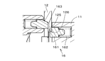
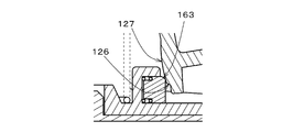
- the movable member 12 When the movable member 12 starts to be pushed from the first position 301, the coil spring 121 and the coil spring 145 are compressed, and as shown in FIG.
- the inclined surface 163 at the tip of the 161 is in contact.
- the portion 125 near the inclined surface 126 of the movable member 12 is referred to as an “engaging portion”.
- the position of the movable member 12 shown in FIG. 3 is a rising start position 321 of the small peak 341.
- the inclined surface 126 and the inclined surface 163 are slightly separated from each other (reference numerals are omitted in FIG. 1), and the first position 301 and the position 321 are close.
- the inclined surface 126 is inclined upward as it goes outward in the horizontal direction.
- the inclined surface 163 is inclined so as to go downward as it goes inward in the lateral direction. Therefore, when the load applied to the movable member 12 is increased, the engaging portion 161 starts moving outward in the lateral direction against the force from the coil spring 162 as shown in FIG. This state is a state from the position 321 to the position 323.
- the vehicle quickly reaches the position 334 from the position 333.
- the position 333 and the position 334 substantially coincide.
- the main peak 342 is obtained.
- the operation cannot be stopped between the small peak 341 and the second position 302 by the normal operation due to the presence of the small peak 341.
- the two contacts 13 are connected in series and provided as one set of double-sided contacts.
- two or more sets of double-sided contacts may be provided in a direction perpendicular to the paper surface.
- the time during which the states of the two sets of double-cut contacts differ can be significantly reduced. That is, it is possible to reduce the shift in the switching timing of the two sets of double-sided contacts. As a result, it is possible to prevent erroneous detection of an error caused by a difference between the states of the two contact points 13 for a certain time or more.
- the two terminals 131 and 132 included in the contact 13 gradually approach and come into contact, so that the contact 13 is closed. become. In this case, by quickly shifting from the small peak 341 to the second position 302, it is possible to suppress discharge when the contact 13 is closed, and to suppress welding of the contact 13.
- the resistance mechanism 16 of the enable switch 1 can be variously modified.
- the combination of the engaging portion 161 and the coil spring 162 can be provided in various places as long as the portion is between the movable member 12 and the holding portion 11.
- the movable member 12 may be provided with an engaging portion 161 and a coil spring 162.
- the holding portion 11 is provided with an inclined surface 112 that is in sliding contact with the inclined surface 163 at the tip of the engaging portion 161.
- the resistance mechanism 16 can be provided in the OFF switching mechanism 14.
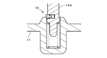
- FIG. 9 is a diagram illustrating an example in which the resistance mechanism 16 is provided in the lower contact portion 144. As described above, when the movable member 12 moves from the first position 301, the resistance mechanism 16 can be provided at various parts that move together with the movable member 12.
- the arrangement direction of the engaging portions 161 and the coil springs 162 is not limited to the horizontal direction of the paper as shown in FIGS. 1, 8, and 9, but may be arranged in a direction perpendicular to the paper.
- the engagement structure of the resistance mechanism 16 can be variously changed.
- the engaging portion 161 is regarded as a first engaging portion
- a portion engaging with the engaging portion 161 (the engaging portion 125 in FIG. 3) is regarded as a second engaging portion
- the second engaging portion is The movable member 12 moves relatively to the first engaging portion. Then, when the movable member 12 is pushed toward the holding portion 11, the engagement between the first engagement portion and the second engagement portion is released, so that a small peak 341 of the load occurs.
- the first engagement portion and the second engagement portion are separated from each other at the first position 301, may be engaged once when the movable member 12 is pressed, and may be released or may be already engaged at the first position 301. May be.
- the small peak 341 can be obtained with a simple structure.
- the first engaging portion does not necessarily need to receive a force from an elastic body such as a spring.
- the first engaging portion may use gravity or magnetic force to make contact with the first engaging portion.
- the second engaging portion may be engaged.
- the elastic body When the first engaging portion receives a force from an elastic body, a leaf spring, a resin flexible portion, or the like can be used as the elastic body other than the coil spring.
- the elastic body may exert a force for engaging between the first engagement portion and the second engagement portion by various methods.
- the elastic body is directly or indirectly fixed to one of the movable member 12 and the holding portion 11.
- the second engaging portion is directly or indirectly attached to the elastic body, and the first engaging portion is directly or indirectly fixed to the other of the movable member 12 and the holding portion 11. Then, when the movable member 12 is pushed in, the second engagement portion moves against the force from the elastic body to release the engagement, so that the small peak 341 is obtained.
- the small peak 341 may be obtained without using the engaging portion.
- a rubber pad that is suddenly dented by being pushed in may be provided between the movable member 12 and the coil spring 121.
- a small peak 341 may be obtained by passing one of a pair of magnets repelling or attracting each other near the other.
- the enable switch 1 described with reference to FIGS. 1 to 9 can be variously changed.
- the enable switch 1 has one set of double-cut contacts, two or more double-cut contacts may be provided as described above.
- a pair of double-cut contacts consisting of four terminals may be one single-cut contact consisting of two terminals.
- the number of one-sided contacts may be one or two or more.
- the movable member 12 may be a lever that rotates when pushed. In the case of a type in which the movable member 12 rotates, the amount of pushing of the movable member 12 corresponds to the rotation angle, and the position of the movable member 12 is a rotation position or a position of a specific portion of the movable member 12.
- the characteristics of the enable switch 1 shown in FIG. 2 can be applied to enable switches having various structures.
- the present invention can be applied to the enable switches disclosed in Japanese Patent Application Laid-Open No. 2002-42606, International Publication No. 2002/061779, and Japanese Patent Application Laid-Open No. 2005-56635.
- various structures can be adopted as the contact mechanism 20.
- the operation unit provided with the enable switch 1 is not limited to the teaching pendant, but can be used for various operation units such as an operation unit of a heavy machine such as a hoist, an operation unit of a vehicle, and an operation unit of an electric wheelchair.
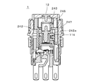
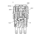
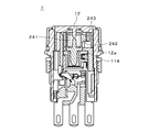
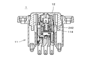
- FIGS. 10 and 11 are longitudinal sectional views of an enable switch 1 according to another example provided in an operation unit such as a teaching pendant of a robot or a controller of a work machine.
- a robot, a work machine, or the like is an operation target of the operation unit.
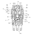
- FIG. 10 is a longitudinal sectional view of the enable switch 1 as viewed from the front
- FIG. 11 is a longitudinal sectional view of the enable switch 1 as seen from the side. In these cross-sectional views, the position of the cross-section of each member is appropriately different in order to easily show the internal structure.
- the enable switch 1 permits the operation of the operation target from the operation unit.
- the enable switch 1 While the enable switch 1 is in the ON state, the operation of the operation target is permitted, and when the operator performs an input to the operation unit, a signal from the operation unit according to the input is transmitted to the operation target.
- the enable switch 1 When the enable switch 1 is in the OFF state, the operation of the operation target is not permitted, and the input of the operator is not transmitted to the operation target.
- the enable switch 1 includes a holding unit 11 and a movable member 12.
- the movable member 12 When the enable switch 1 is operated, the movable member 12 is pushed into the holding unit 11 downward in FIGS. 10 and 11 by an operator.
- the vertical direction in FIGS. 10 and 11 need not coincide with the direction of gravity.
- the holding unit 11 supports members other than the holding unit 11 of the enable switch 1.
- FIG. 10 a force is applied to the movable member 12 in the upward direction in FIG.
- the coil spring 121 and other coil springs are shown in a simplified manner by broken lines.
- the enable switch 1 includes two contacts 13, a contact mechanism 20 that opens and closes the state of the contacts 13, and two auxiliary switches 21 in the holding unit 11.
- Each contact 13 is a combination of a lower fixed terminal 131 and a movable terminal 132.
- there is also an upper fixed terminal, and a connection terminal group 134 including three connection terminals connected to the upper fixed terminal, the lower fixed terminal 131, and the movable terminal 132, respectively, is located below the holding unit 11.
- the contact 13 is open, the lower fixed terminal 131 and the movable terminal 132 are separated.
- the enable switch 1 is OFF, and when the contact 13 is closed, the enable switch 1 is ON.
- the movable member 12 is horizontally long in the left-right direction in FIG. 10, and the movable member 12 is pushed into the holding unit 11 in a downward direction perpendicular to the direction in which the movable member 12 extends.
- An OFF switching mechanism 14 is arranged inside the movable member 12.
- the OFF switching mechanism 14 includes three vertical coil springs 241, a contact member 242 that accommodates the vertical coil springs 241, two sliders 243, two horizontal coil springs 244, and two pushing members 245.
- the contact member 242 is divided into three parts (parts denoted by reference numerals 242 and 242 a) that accommodate the three vertical coil springs 241, but these are one member.
- a hole is provided in the lower member 12a of the movable member 12, and the contact member 242 is fitted into the hole of the lower member 12a.
- a slider 243 and a horizontal coil spring 244 are arranged in a space between the upper part of the movable member 12 and the lower member 12a.
- the slider 243 receives a force inward in the horizontal direction from the horizontal coil spring 244, the contact member 242 receives a downward force from the vertical coil spring 241, and the tip of the slider 243 is It is located above.
- the upper end of the pushing member 245 is close to the lower end of the rear end 243a of the slider 243.
- the movable terminal 132 is connected to the snap mechanism 133. As described later, when the pushing member 245 is pushed to a predetermined position, the movable terminal 132 is quickly moved toward the lower fixed terminal 131 by the spring of the snap mechanism 133, and the movable terminal 132 and the lower fixed terminal 131 are moved. 131 contacts. That is, the contact 13 is closed.
- the OFF switching mechanism 14 and the snap mechanism 133 switch the state of the contact 13 from open to closed and further from closed to open as the movable member 12 is pushed toward the holding portion 11.
- the mechanism 20 is configured. Since the enable switch 1 has two contacts 13, when these are distinguished from the “first contact 13” and the “second contact 13”, the contact mechanism 20 pushes the movable member 12 toward the holding unit 11. Accordingly, the states of the first contact 13 and the second contact 13 shift from open to closed, and further shift from closed to open.
- the first contact 13 and the second contact 13 are arranged in a direction in which the movable member 12 extends.
- the contact mechanism 20 further includes a resistance mechanism 16 provided below the OFF switching mechanism 14.
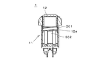
- the resistance mechanism 16 includes a rotating member 261 that is long in the direction in which the movable member 12 extends.
- the rotating member 261 is formed by bending both ends twice at 90 ° so that both ends of the metal bar face inward.
- the rotating member 261 may be formed by bending both ends of the metal bar by 90 degrees and then bending the metal rods so that the portions on both ends face outward.
- the rotation member 261 is rotatable around a rotation axis J1 parallel to the direction in which the rotation member 261 extends. Both ends of the rotating member 261 are sandwiched between the lower member 262 and the upper member (see reference numeral 111a in FIG. 17).
- the rotating member 261 is directly and rotatably attached to the movable member 12 such that the upper part of the rotating member 261 is engaged with the lower member 12 a of the movable member 12.
- a part of the member 262 located below the rotating member 261 is also included in the resistance mechanism 16.
- the member 262 includes a concave portion 264 in which the lower portion 263 of the rotating member 261 fits. In the initial state shown in FIGS. 10 and 11, the lower portion 263 of the rotating member 261 is located outside the concave portion 264.
- FIG. 12 is a diagram schematically illustrating the relationship between the amount of movement of the movable member 12, that is, the amount of depression of the enable switch 1, and the load.
- the position of the movable member 12 corresponding to the pushing amount will be described with reference to the reference numerals shown in FIG.
- position 301 is an initial position.
- the position 301 is referred to as a “first position”.
- the first position 301 is a position of the movable member 12 with respect to the holding unit 11 in a state where the movable member 12 is not pushed.
- the position 303 is a position of the movable member 12 with respect to the holding unit 11 in a state where the movable member 12 is pushed in most.
- the position 303 is referred to as a “third position”. At the third position 303, the enable switch 1 is in the OFF state.
- the position 302 is a position where the movable member 12 can be stably held by pushing the movable member 12 to some extent and allowing the operator to feel a certain resistance. Thereby, the enable switch 1 is stably held in the ON state.
- the position 302 is referred to as a “second position”.
- the second position 302 rises at the maximum rise 343 where the load required for pushing the movable member 12 rises to the maximum when the rate of increase of the load with respect to the pushing amount increases between the first position 301 and the third position 303. Start position.
- the position 311 is an “ON switching position” where the contact 13 shifts from open to closed when the switch is pushed in, and the enable switch 1 shifts from an OFF state to an ON state.
- the position 312 is an “OFF switching position” where the contact 13 shifts from the closed state to the open state and the enable switch 1 shifts from the ON state to the OFF state. Accordingly, in the enable switch 1, when the movable member 12 is pushed in, the contact 13 shifts from open to closed at the ON switching position 311 between the first position 301 and the second position 302, and the second position 302 At the OFF switching position 312 between the third position 303 and the third position 303, the contact 13 shifts from closed to open.
- the enable switch 1 since the enable switch 1 has two contacts 13, when these are distinguished from the “first contact 13” and the “second contact 13”, when the movable member 12 is pushed in, the first position 301 and The first contact 13 shifts from open to closed at the first ON switching position between the second position 302 and the first contact 13 at the first OFF switching position between the second position 302 and the third position 303.
- the second contact 13 shifts from open to closed at the second ON switching position between the first position 301 and the second position 302, and changes from the second position 302 to the third position 303.
- the second contact 13 shifts from closed to open at the second OFF switching position.
- the position 311 in FIG. 12 corresponds to the first ON switching position
- the position 312 corresponds to the first OFF switching position 312.
- the position 311 corresponds to the second ON switching position
- the position 312 corresponds to the second OFF switching position 312. Then, the first ON switching position and the second ON switching position match or approach each other, and the first OFF switching position and the second OFF switching position match or approach each other.
- reference numeral 321 indicates a position where the rising of the small peak 341 starts
- reference numeral 322 indicates a position where the rising ends and the maintenance of a certain load starts
- reference numeral 323 indicates a position where the falling starts, and the falling ends.
- the position is denoted by reference numeral 324.
- these positions do not need to appear clearly, and if they do not appear, they may be specified in various ways.
- the positions where the curvature is the largest may be specified as the positions 321 and 324.
- the position 322 and the position 323 may be similarly defined, and the positions 322 and 323 may coincide.
- the position 322 and the position 323 are specified as the same position.
- a position where the gradient of the load when the pushing amount is increased exceeds a certain positive value is specified as a rising start position 321, and a position below a certain value is specified as a rising end position 322. Further, a position below a certain negative value is specified as a falling start position 323, and a position exceeding a certain value is specified as a falling end position 324.
- the rising start position of the peak between the second position 302 and the third position 303 (second position 302), the rising end position 332, the falling start position 333, and the falling end position 334 have roughly the meanings.
- the position shown may be determined by various methods.
- the rising end position 332 and the falling start position 333 may coincide with each other.
- the peak from the position 302 to the position 334 is referred to as a “main peak 342”.
- the ON switching position 311 (specifically, the first ON switching position and the second ON switching position, the same applies hereinafter) includes the falling end position 324 of the small peak 341 and the second position 302. Located between. Further, the maximum load A1 at the small peak is equal to or more than the load A2 at the ON switching position 311 (specifically, the larger one of the load at the first ON switching position and the load at the second ON switching position), and the OFF switching. The load A3 at the position 312 (specifically, the smaller one of the load at the first OFF switching position and the load at the second OFF switching position) is smaller.
- the movable member 12 When the movable member 12 starts to be pushed, the movable member 12 is pushed in at a stretch after a slight click feeling and shifts to the second position 302. That is, in a normal operation, if the peak exceeds the small peak 341, the movable member 12 cannot be stopped halfway, and quickly shifts to the second position 302 as if the movable member 12 hits something. As a result, the operator can clearly sense that the movable member 12 is located at the second position 302. In other words, the worker can clearly feel the increase in the load with respect to the pushing amount at the stage before the second position 302 is further pushed from the ON state to the OFF state of the third position 303.
- the ON switching position 311 is not limited to the position shown in FIG.
- the ON switching position 311 may be located between the falling start position 323 of the small peak 341 and the second position 302. Further, from the viewpoint of moving the movable member 12 from the small peak 341 to the second position 302 promptly, it is preferable that the maximum load A1 of the small peak 341 is larger than the load A4 at the second position 302.
- the maximum load of the small peak 341 is preferably a load at a position immediately before the OFF switching position 312 (in detail, , The load at the position immediately before the first OFF switching position and the second OFF switching position, and is usually smaller than the load at the position 332).
- the rising start position 321 of the small peak 341 may substantially coincide with the first position 301, or may coincide with the first position 301. Even in such a case, the worker can feel the catch when pushing the movable member 12. In particular, when the rising of the small peak 341 is substantially vertical, that is, when the position 321 and the position 322 are almost coincident, the operator can more clearly feel the catch. Of course, even when the rising start position 321 of the small peak 341 is far from the first position 301, the rising of the small peak 341 is preferably substantially vertical.
- the small peak 341 and the second position 302 must be sufficiently separated.
- the maximum load position of the small peak 341 is preferably closer to the first position 301 than an intermediate position between the first position 301 and the second position 302. This is because if the small peak 341 is close to the second position 302, there is a possibility that the small peak 341 is mistaken for the main peak 342.
- the enable switch 1 having the characteristics shown in FIG. 12, even if the small peak 341 is provided, it is not necessary to change the load required for holding the movable member 12 in the second position 302 by design. Even if the part is held in the second position 302 for a long time, the burden on the operator does not increase. Further, by providing the small peak 341, an effect of preventing the enable switch 1 from being inadvertently turned ON when the movable member 12 is accidentally touched or another object comes into contact with the movable member 12 can be obtained. .
- the change in load from the fall of the small peak 341 to the second position 302 is shown by a straight line, but the change is not limited to a straight line as long as there is no large change.
- the load change rate may change at the ON switching position 311 and the load curve may be bent, or the load may slightly change at the ON switching position 311 in a stepped manner.
- the lower portion 263 of the rotating member 261 slides on the upper surface of the member 262 while the coil spring 121 is compressed, as shown in FIG.
- the lower portion 263 of the rotating member 261 is referred to as a “rotating sliding contact portion”
- the member 262 is referred to as a “fixed sliding contact portion”.
- the rotation sliding contact portion 263 engages with the recess 264 so as to fit.
- the position of the movable member 12 shown in FIG. 13 is the rising start position 321 of the small peak 341.
- the rotary sliding contact portion 263 and the concave portion 264 are slightly apart, and the first position 301 and the position 321 are close.
- the upper surface at the center of the contact member 242 includes an inclined surface 246 that goes downward as it goes laterally outward.
- the lower surface of the tip end of the slider 243 includes an inclined surface 247 that is directed upward in the horizontal direction.
- the inclined surface 246 and the inclined surface 247 are substantially parallel to each other.
- the movable member 12 descends so that the outer surface of the upper end of the center of the contact member 242 and the tip of the slider 243 rub against each other. At this time, the load decreases at a stretch. Therefore, the position 334 is quickly reached from the position 333. In the case of the enable switch 1 shown in FIGS. 10 and 11, the position 333 and the position 334 almost coincide with each other. By the above operation, the main peak 342 is obtained.
- FIGS. 18 and 19 are views showing a state where the movable member 12 is pushed in the most.
- the slider 243 moves outward in the horizontal direction at the OFF switching position 312 before the state shown in FIGS. 18 and 19, the vertical contact state between the rear end 243a of the slider 243 and the pushing member 245 is released. Is done.
- the push-in member 245 is raised by receiving the force from the snap mechanism 133, and the contact 13 is changed from closed to open.
- both of the two auxiliary switches 21 are ON, in the states of FIGS. 16 and 17, only one is ON, and in the state of FIG. 18, both are OFF.
- the signal from the auxiliary switch 21 is used variously on the operation unit side. For example, when both the auxiliary switches 21 are ON when the enable switch 1 is OFF, the operation unit determines that the enable switch 1 is in the first position 301. When both the auxiliary switches 21 are in the OFF state when the enable switch 1 is in the OFF state, the operation unit determines that the enable switch 1 is in the third position 303.
- the operation cannot be stopped between the small peak 341 and the second position 302 by the normal operation due to the presence of the small peak 341. Has reached the second position 302. Further, when two contacts 13 exist for improving the reliability as in the case of the enable switch 1, the transition from the small peak 341 to the second position 302 promptly shifts the two contacts 13 even if the movable member 12 is inclined. The time during which the states 13 differ can be made very short. That is, it is possible to reduce the shift of the switching timing of the two contacts 13. As a result, it is possible to prevent erroneous detection of an error caused by a difference between the states of the two contact points 13 for a certain time or more.
- the small peak 341 of the load is obtained by the engagement of the rotating sliding contact portion 263 of the rotating member 261 and the concave portion 264 of the fixed sliding contact portion 262. Further, the rotary sliding contact portion 263 exists only at both ends in the longitudinal direction of the rotary member 261.
- the concave portion 264 very shallow, when the center of the movable member 12 is pressed, the rotary sliding contact portion 263 is moved so as to slide on the concave portion 264, and the end of the rotary member 261 is pressed.
- the rotary sliding contact portion 263 existing at the end of the rotary member 261 may be strongly fitted into the concave portion 264 to obtain a small peak 341 of the load.
- the small peak 341 is eliminated, or the small peak 341 is reduced, and when the end of the rotating member 261 is pressed, a large small peak 341 is obtained. You may be.
- the resistance mechanism 16 of the enable switch 1 can be variously modified.
- the rotation axis J1 of the rotation member 261 may be provided near the fixed sliding contact portion 262, and the concave portion may be provided on the lower member 12a side. That is, the rotating member 261 may rotate around the lower part.
- a convex portion (including a step) may be provided instead of the concave portion.
- the rotating member 261 can be directly or indirectly rotatably attached to one of the movable member 12 and the holding portion 11, and the fixed sliding contact portion 262 is directly connected to the other of the movable member 12 and the holding portion 11. Or it can be fixed indirectly. When the rotating member 261 rotates while the rotating sliding portion 263 and the fixed sliding portion 262 slide, the movable member 12 is pushed into the holding portion 11 while the posture of the movable member 12 is maintained.
- the resistance mechanism 16 may be provided by a structure other than the rotating member 261.
- an engaging portion and a coil spring disposed between the holding portion 11 and the engaging portion may be provided.
- the engaging portion receiving the force from the coil spring engages with the movable member 12, and the movable member 12 is pressed to move the engaging portion against the force from the coil spring, and then the engagement is released.
- a small peak 341 is obtained.
- an engagement portion and a coil spring disposed between the movable member 12 and the engagement portion may be provided.
- the engaging portion receiving the force from the coil spring engages with the holding portion 11, and the movable member 12 is pressed to release the engagement, so that a small peak 341 is obtained.
- the resistance mechanism 16 may be provided indirectly between the holding unit 11 and the movable member 12.
- the engagement structure of the resistance mechanism 16 can be variously changed.
- One engaging portion (the concave portion 264 in FIG. 11) is regarded as the first engaging portion, and the other engaging portion (the rotary sliding contact portion 263 in FIG. 11) that engages with the first engaging portion.
- the second engaging portion moves relative to the first engaging portion by the movement of the movable member 12. Then, when the movable member 12 is pushed toward the holding portion 11, the engagement between the first engagement portion and the second engagement portion is released, so that a small peak 341 of the load occurs.
- the first engagement portion and the second engagement portion are separated from each other at the first position 301, may be engaged once when the movable member 12 is pressed, and may be released or may be already engaged at the first position 301. May be.
- the small peak 341 can be obtained with a simple structure.
- the first engaging portion does not necessarily need to receive a force from an elastic body such as a spring.
- an elastic body such as a spring.
- the first engagement portion and the second engagement portion may be engaged using gravity. Magnetic force may be used for the engagement.
- the elastic body When the first engaging portion receives a force from an elastic body, a leaf spring, a resin flexible portion, or the like can be used as the elastic body other than the coil spring.
- the elastic body may exert a force for engaging between the first engagement portion and the second engagement portion by various methods.
- the elastic body is directly or indirectly fixed to one of the movable member 12 and the holding portion 11.
- the second engaging portion is directly or indirectly attached to the elastic body, and the first engaging portion is directly or indirectly fixed to the other of the movable member 12 and the holding portion 11. Then, when the movable member 12 is pushed in, the second engagement portion moves against the force from the elastic body to release the engagement, so that the small peak 341 is obtained.
- the small peak 341 may be obtained without using the engaging portion.
- a rubber pad that is suddenly dented by being pushed in may be provided between the movable member 12 and the coil spring 121.
- a small peak 341 may be obtained by passing one of a pair of magnets repelling or attracting each other near the other.
- the enable switch 1 described with reference to FIGS. 10 to 19 can be variously changed.
- the number of contacts may be three or more.
- the movable member 12 may be a lever that rotates when pushed. In the case where the movable member 12 rotates, the amount of pushing the movable member 12 corresponds to the rotation angle.
- the characteristics of the enable switch 1 shown in FIG. 12 can be applied to enable switches having various structures.
- the present invention can be applied to the enable switch disclosed in Japanese Patent Application Laid-Open No. 2001-35300, International Publication No. 2002/061779, and Japanese Patent Application Laid-Open No. 2005-56635.
- various structures can be adopted as the contact mechanism 20.
- the contact 13 is opened and closed using a snap action.
- the movable member 12 is included in the contact 13 as the movable member 12 is pushed into the holding portion 11 near the ON switching position 311.
- the contact may be closed as the two terminals gradually approach and come into contact. In this case, by quickly shifting from the small peak 341 to the second position 302, it is possible to suppress discharge when the contact 13 is closed, and to suppress welding of the contact 13.
- the operation unit provided with the enable switch 1 is not limited to the teaching pendant, but can be used for various operation units such as an operation unit of a heavy machine such as a hoist, an operation unit of a vehicle, and an operation unit of an electric wheelchair.
- FIGS. 20 and 21 are longitudinal sectional views of an enable switch 1 according to still another example provided in an operation unit such as a teaching pendant of a robot or a controller of a work machine.
- a robot, a work machine, or the like is an operation target of the operation unit.
- FIG. 20 is a longitudinal sectional view of the enable switch 1 as viewed from the front
- FIG. 21 is a longitudinal sectional view of the enable switch 1 as seen from the side.
- the position of the cross-section of each member is appropriately different in order to easily show the internal structure.
- the enable switch 1 permits the operation of the operation target from the operation unit.
- the enable switch 1 While the enable switch 1 is in the ON state, the operation of the operation target is permitted, and when the operator performs an input to the operation unit, a signal from the operation unit according to the input is transmitted to the operation target.
- the enable switch 1 When the enable switch 1 is in the OFF state, the operation of the operation target is not permitted, and the input of the operator is not transmitted to the operation target.
- the enable switch 1 includes a holding unit 11 and a movable member 12.
- the movable member 12 When operating the enable switch 1, the movable member 12 is pushed into the holding unit 11 downward in FIGS. 20 and 21 by an operator. 20 and 21 need not coincide with the direction of gravity.
- the holding unit 11 supports members other than the holding unit 11 of the enable switch 1.
- the upward force in FIG. 20 is applied to the movable member 12 by the coil spring 121 in the holding unit 11 shown in FIG. In FIG. 20, the coil spring 121 and other coil springs are shown in simplified form by broken lines.
- the movable member 12 When the operator's finger releases the movable member 12 after pushing the movable member 12 into the holding portion 11, the movable member 12 returns to the original position by the force of the coil spring 121. When the movable member 12 is pushed into the holding portion 11, the movable member 12 rotates around the fulcrum 123a.
- the enable switch 1 includes two contacts 13 (see FIG. 21) and a contact mechanism 20 that opens and closes the state of the contacts 13 in the holding unit 11.
- Each contact 13 is a combination of a lower fixed terminal 131 and a movable terminal 132.
- there is also an upper fixed terminal, and a connection terminal group 134 including three connection terminals connected to the upper fixed terminal, the lower fixed terminal 131, and the movable terminal 132, respectively, is located below the holding unit 11.
- the contact 13 is open, the lower fixed terminal 131 and the movable terminal 132 are separated.
- the enable switch 1 is OFF, and when the contact 13 is closed, the enable switch 1 is ON.
- the movable member 12 is covered with a soft resin cover 124a.
- the movable member 12 is pushed from above the cover 124a. Therefore, while the movable member 12 is being pushed in, the cover 124a bends, but in the following drawings, the bending of the cover 124a is ignored.
- An OFF switching mechanism 14 is arranged inside the movable member 12.
- the OFF switching mechanism 14 includes a vertical coil spring 241, an abutting member 242 that houses the vertical coil spring 241, a slider 243, a horizontal coil spring 244, and a pushing member 245.
- a hole is provided in the lower member 12a of the movable member 12, and the contact member 242 is fitted into the hole of the lower member 12a.
- a slider 243 and a horizontal coil spring 244 are arranged in a space between the upper part of the movable member 12 and the lower member 12a.
- the slider 243 receives a leftward force from the horizontal coil spring 244, the contact member 242 receives a downward force from the vertical coil spring 241 and the left portion 243b of the right end of the slider 243.
- the contact member 242 receives a downward force from the vertical coil spring 241 and the left portion 243b of the right end of the slider 243.
- the upper end of the pushing member 245 is close to the lower end of the rear end 243a of the slider 243.
- the movable terminal 132 is connected to the snap mechanism 133. As described later, when the pushing member 245 is pushed to a predetermined position, the movable terminal 132 is quickly moved toward the lower fixed terminal 131 by the spring of the snap mechanism 133, and the movable terminal 132 and the lower fixed terminal 131 are moved. 131 contacts. That is, the contact 13 is closed.
- the OFF switching mechanism 14 and the snap mechanism 133 switch the state of the contact 13 from open to closed and further from closed to open as the movable member 12 is pushed toward the holding portion 11.
- the mechanism 20 is configured. Since the enable switch 1 has two contacts 13, when these are distinguished from the “first contact 13” and the “second contact 13”, the contact mechanism 20 pushes the movable member 12 toward the holding unit 11. Accordingly, the states of the first contact 13 and the second contact 13 shift from open to closed, and further shift from closed to open.
- Contact mechanism 20 further includes resistance mechanism 16 provided near coil spring 121.
- the resistance mechanism 16 is provided in a hole that opens to the right in FIG.
- the resistance mechanism 16 includes an engagement portion 161 and a coil spring 162.
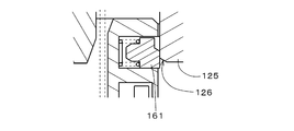
- the coil spring 162 pushes the engagement portion 161 toward the right in FIG. 20, that is, toward the lower portion 125 of the inner wall of the movable member 12.
- the tip of the engaging portion 161 contacts the lower portion 125 of the inner wall.
- the resistance mechanism 16 applies a force to the movable member 12 to resist the movement of the movable member 12 in an initial stage of pushing the movable member 12 as described later.
- FIG. 22 is a diagram schematically illustrating the relationship between the rotational position of the movable member 12, that is, the amount of depression of the enable switch 1, which is the amount of movement of a specific portion of the movable member 12, and the load.
- the position of the movable member 12 corresponding to the pushing amount will be described with reference to the reference numerals shown in FIG.
- position 301 is an initial position.
- the position 301 is referred to as a “first position”.
- the first position 301 is a position of the movable member 12 with respect to the holding unit 11 in a state where the movable member 12 is not pushed.
- the position 303 is a position of the movable member 12 with respect to the holding unit 11 in a state where the movable member 12 is pushed in most.
- the position 303 is referred to as a “third position”. At the third position 303, the enable switch 1 is in the OFF state.
- the position 302 is a position where the movable member 12 can be stably held by pushing the movable member 12 to some extent and allowing the operator to feel a certain resistance. Thereby, the enable switch 1 is stably held in the ON state.
- the position 302 is referred to as a “second position”.
- the second position 302 rises at the maximum rise 343 where the load required for pushing the movable member 12 rises to the maximum when the rate of increase of the load with respect to the pushing amount increases between the first position 301 and the third position 303. Start position.
- the position 311 is an “ON switching position” where the contact 13 shifts from open to closed when the switch is pushed in, and the enable switch 1 shifts from an OFF state to an ON state.
- the position 312 is an “OFF switching position” where the contact 13 shifts from the closed state to the open state and the enable switch 1 shifts from the ON state to the OFF state. Accordingly, in the enable switch 1, when the movable member 12 is pushed in, the contact 13 shifts from open to closed at the ON switching position 311 between the first position 301 and the second position 302, and the second position 302 At the OFF switching position 312 between the third position 303 and the third position 303, the contact 13 shifts from closed to open.
- the enable switch 1 since the enable switch 1 has two contacts 13, when these are distinguished from the “first contact 13” and the “second contact 13”, when the movable member 12 is pushed in, the first position 301 and The first contact 13 shifts from open to closed at the first ON switching position between the second position 302 and the first contact 13 at the first OFF switching position between the second position 302 and the third position 303.
- the second contact 13 shifts from open to closed at the second ON switching position between the first position 301 and the second position 302, and changes from the second position 302 to the third position 303.
- the second contact 13 shifts from closed to open at the second OFF switching position.
- the position 311 in FIG. 22 corresponds to the first ON switching position
- the position 312 corresponds to the first OFF switching position 312.
- the position 311 corresponds to the second ON switching position
- the position 312 corresponds to the second OFF switching position 312. Then, the first ON switching position and the second ON switching position match or approach each other, and the first OFF switching position and the second OFF switching position match or approach each other.
- reference numeral 321 indicates a position where the rising of the small peak 341 starts
- reference numeral 322 indicates a position where the rising ends and maintenance of a certain load starts
- reference numeral 323 indicates a position where the falling starts, and the falling ends.
- the position is denoted by reference numeral 324.
- these positions do not need to appear clearly, and if they do not appear, they may be specified in various ways.
- the positions where the curvature is the largest may be specified as the positions 321 and 324.
- the position 322 and the position 323 may be similarly defined, and the positions 322 and 323 may coincide.
- the position 322 and the position 323 are specified as the same position.
- a position where the gradient of the load when the pushing amount is increased exceeds a certain positive value is specified as a rising start position 321, and a position below a certain value is specified as a rising end position 322. Further, a position below a certain negative value is specified as a falling start position 323, and a position exceeding a certain value is specified as a falling end position 324.
- the rising start position of the peak between the second position 302 and the third position 303 (second position 302), the rising end position 332, the falling start position 333, and the falling end position 334 have roughly the meanings.
- the position shown may be determined by various methods.
- the rising end position 332 and the falling start position 333 may coincide with each other.
- the peak from the position 302 to the position 334 is referred to as a “main peak 342”.
- the ON switching position 311 (specifically, the first ON switching position and the second ON switching position, the same applies hereinafter) includes the falling end position 324 of the small peak 341 and the second position 302. Located between. Further, the maximum load A1 at the small peak is equal to or more than the load A2 at the ON switching position 311 (specifically, the larger one of the load at the first ON switching position and the load at the second ON switching position), and the OFF switching. The load A3 at the position 312 (specifically, the smaller one of the load at the first OFF switching position and the load at the second OFF switching position) is smaller.
- the movable member 12 When the movable member 12 starts to be pushed, the movable member 12 is pushed in at a stretch after a slight click feeling and shifts to the second position 302. That is, in a normal operation, if the peak exceeds the small peak 341, the movable member 12 cannot be stopped halfway, and quickly shifts to the second position 302 as if the movable member 12 hits something. As a result, the operator can clearly sense that the movable member 12 is located at the second position 302. In other words, the worker can clearly feel the increase in the load with respect to the pushing amount at the stage before the second position 302 is further pushed from the ON state to the OFF state of the third position 303.
- the ON switching position 311 is not limited to the position shown in FIG.
- the ON switching position 311 may be located between the falling start position 323 of the small peak 341 and the second position 302. Further, from the viewpoint of moving the movable member 12 from the small peak 341 to the second position 302 promptly, it is preferable that the maximum load A1 of the small peak 341 is larger than the load A4 at the second position 302.
- the maximum load of the small peak 341 is preferably a load at a position immediately before the OFF switching position 312 (in detail, , The load at the position immediately before the first OFF switching position and the second OFF switching position, and is usually smaller than the load at the position 332).
- the rising start position 321 of the small peak 341 may substantially coincide with the first position 301, or may coincide with the first position 301. Even in such a case, the worker can feel the catch when pushing the movable member 12. In particular, when the rising of the small peak 341 is substantially vertical, that is, when the position 321 and the position 322 are almost coincident, the operator can more clearly feel the catch. Of course, even when the rising start position 321 of the small peak 341 is far from the first position 301, the rising of the small peak 341 is preferably substantially vertical.
- the small peak 341 and the second position 302 must be sufficiently separated.
- the maximum load position of the small peak 341 is preferably closer to the first position 301 than an intermediate position between the first position 301 and the second position 302. This is because if the small peak 341 is close to the second position 302, there is a possibility that the small peak 341 is mistaken for the main peak 342.
- the load required to hold the movable member 12 at the second position 302 does not need to be changed by design even if the small peak 341 is provided. Even if the part is held in the second position 302 for a long time, the burden on the operator does not increase. Further, by providing the small peak 341, an effect of preventing the enable switch 1 from being inadvertently turned ON when the movable member 12 is accidentally touched or another object comes into contact with the movable member 12 can be obtained. .
- the change in load from the fall of the small peak 341 to the second position 302 is indicated by a straight line, but the change is not limited to a straight line as long as there is no large change.
- the load change rate may change at the ON switching position 311 and the load curve may be bent, or the load may slightly change at the ON switching position 311 in a stepped manner.
- FIG. 23 is an enlarged view showing the resistance mechanism 16 when the movable member 12 is located at the first position 301.
- the tip of the engaging portion 161 has an inclined surface 163.
- the lower part 125 of the inner wall of the movable member 12 has an inclined surface 126.
- the engaging portion 161 and the lower portion 125 are engaged with each other so that the inclined surface 163 and the inclined surface 126 are in parallel contact with each other.
- the lower portion 125 of the inner wall of the movable member 12 is referred to as an “engaging portion”.
- the inclined surface 163 goes downward as it goes rightward in FIG.
- the inclined surface 126 is directed upward toward the left.
- the upper surface of the right portion 242b of the contact member 242 includes an inclined surface 246 that is directed downward toward the right.
- the left side portion 243b of the right end portion of the slider 243 that is, the lower surface of the portion on the contact member 242 side includes an inclined surface 247 that is upward toward the left.
- the inclined surface 246 and the inclined surface 247 are substantially parallel to each other.
- the movable member 12 rises while the rear end 243a of the slider 243 and the pushing member 245 are displaced in the lateral direction.
- the slider 243 is located above the upper end of the pushing member 245, the rear end 243a of the slider 243 is located immediately above the pushing member 245 under the force of the horizontal coil spring 244, as shown in FIG.
- the contact 13 is kept open until the movable member 12 returns to the first position 301 in FIG. That is, when the movable member 12 returns from the third position 303, the OFF state of the enable switch 1 is maintained.
- the movable member 12 returns to the first position 301 and the enable switch 1 returns to the OFF state.
- the operation cannot be stopped between the small peak 341 and the second position 302 by the normal operation due to the presence of the small peak 341. Has reached the second position 302. Further, when two contacts 13 exist for improving the reliability as in the case of the enable switch 1, the transition from the small peak 341 to the second position 302 promptly shifts the two contacts 13 even if the movable member 12 is inclined. The time during which the states 13 differ can be made very short. That is, it is possible to reduce the shift of the switching timing of the two contacts 13. As a result, it is possible to prevent erroneous detection of an error caused by a difference between the states of the two contact points 13 for a certain time or more.
- FIGS. 30 and 31 are longitudinal sectional views of an enable switch 1 according to still another example.
- FIG. 30 is a longitudinal sectional view of the enable switch 1 as viewed from the front
- FIG. 31 is a longitudinal sectional view of the enable switch 1 as seen from the side.
- FIG. 32 is a cross-sectional view of the enable switch 1 at the position of XIII-XIII in FIG.
- the enable switch 1 includes a holding unit 11 and a movable member 12.
- the movable member 12 When operating the enable switch 1, the movable member 12 is pushed into the holding portion 11 downward in FIGS. 30 and 31 by the operator.
- the vertical direction in FIGS. 30 and 31 does not need to coincide with the direction of gravity.
- the holding unit 11 supports members other than the holding unit 11 of the enable switch 1.
- An upward force in FIG. 30 is applied to the movable member 12 indirectly by the coil spring 121 in the holding unit 11 shown in FIG.
- the coil spring 121 and other coil springs are shown in a simplified manner by broken lines.
- the movable member 12 When the operator's finger separates the movable member 12 from the movable member 12 after pushing the movable member 12 into the holding portion 11, the movable member 12 returns to the original position by the force of the coil spring 121 (or the coil spring 121 and a vertical coil spring 241 described later). Return to position.
- the enable switch 1 includes two contacts 13 (see FIG. 31) in the holding unit 11 and a contact mechanism 20 for opening and closing the state of the contacts 13.
- Each contact 13 is a combination of a lower fixed terminal 131 and a movable terminal 132.
- there is also an upper fixed terminal, and a connection terminal group 134 including three connection terminals connected to the upper fixed terminal, the lower fixed terminal 131, and the movable terminal 132, respectively, is located below the holding unit 11.
- the contact 13 is open, the lower fixed terminal 131 and the movable terminal 132 are separated.
- the enable switch 1 is OFF, and when the contact 13 is closed, the enable switch 1 is ON.
- the OFF switching mechanism 14 is disposed inside and below the movable member 12.
- the OFF switching mechanism 14 includes a vertical coil spring 241, a contact member 242 that houses the vertical coil spring 241, a slider 243, two horizontal coil springs 244 (see FIG. 32), and a pushing member 245.
- a hole is provided in the lower member 12a of the movable member 12, and the contact member 242 is fitted into the hole of the lower member 12a.
- the two horizontal coil springs 244 are located on both sides of the slider 243, and apply a force toward the left in FIG.
- a slider 243 and a horizontal coil spring 244 are arranged in a space between the upper part of the movable member 12 and the lower member 12a.
- the slider 243 receives a leftward force from the horizontal coil spring 244, the contact member 242 receives a downward force from the vertical coil spring 241, and the right end of the slider 243 has a contact member 242. Is located above the site on the right. The upper end of the pushing member 245 is close to the lower end of the rear end 243a of the slider 243.
- the movable terminal 132 is connected to the snap mechanism 133. As described later, when the pushing member 245 is pushed to a predetermined position, the movable terminal 132 is quickly moved toward the lower fixed terminal 131 by the spring of the snap mechanism 133, and the movable terminal 132 and the lower fixed terminal 131 are moved. 131 contacts. That is, the contact 13 is closed.
- the OFF switching mechanism 14 and the snap mechanism 133 switch the state of the contact 13 from open to closed and further from closed to open as the movable member 12 is pushed toward the holding portion 11.
- the mechanism 20 is configured. Since the enable switch 1 has two contacts 13, when these are distinguished from the “first contact 13” and the “second contact 13”, the contact mechanism 20 pushes the movable member 12 toward the holding unit 11. Accordingly, the states of the first contact 13 and the second contact 13 shift from open to closed, and further shift from closed to open.
- the contact mechanism 20 further includes a resistance mechanism 16 provided near the lower portion of the lower member 12a.
- the resistance mechanism 16 is provided in a hole that opens rightward in the central member 114 that is a part of the holding unit 11.
- the resistance mechanism 16 includes an engagement portion 161 and a coil spring 162. To be precise, the portion of the central member 114 near the engagement portion 161 and the coil spring 162 is also a part of the resistance mechanism 16.
- the coil spring 162 pushes the engaging portion 161 rightward in FIG. 30, that is, toward the lower portion 125 of the lower member 12a. In the initial state shown in FIG. 30, the engaging portion 161 contacts the lower portion 125.
- the resistance mechanism 16 applies a force to the movable member 12 to resist the movement of the movable member 12 in an initial stage of pushing the movable member 12 as described later.
- FIG. 33 is an enlarged view showing the resistance mechanism 16 when the movable member 12 is located at the first position 301.
- the tip of the engaging portion 161 has an inclined surface 163.
- the lower portion 125 of the lower member 12a has an inclined surface 126.
- the inclined surface 163 and the inclined surface 126 are slightly separated from each other and are parallel to each other.
- the lower portion 125 of the lower member 12a is referred to as an “engaging portion”.
- the inclined surface 163 goes downward as it goes rightward in FIG.
- the inclined surface 126 is directed upward toward the left.
- the position of the movable member 12 in FIG. 34 is the rising start position 321 of the small peak 341. As shown in FIG. 33, at the first position 301, the inclined surface 126 and the inclined surface 163 are only slightly separated from each other, so the first position 301 and the position 321 are close.
- the upper surface of the right side portion of the contact member 242 includes an inclined surface 246 that is directed downward toward the right.
- the lower surface of the right end portion of the slider 243 includes an inclined surface 247 that goes upward toward the left.
- the inclined surface 246 and the inclined surface 247 are substantially parallel to each other.
- the vertical coil spring 241 expands before the coil spring 121, and the rear end portion 243a of the slider 243 and the pushing member 245, as shown in FIG.
- the movable member 12 rises with the position shifted in the lateral direction.
- the rear end 243a of the slider 243 is located immediately above the pushing member 245 by receiving the force from the horizontal coil spring 244 as shown in FIG. Thereafter, the coil spring 121 expands. Thereby, the contact 13 is kept open until the movable member 12 returns to the first position 301 in FIG.
- the movable member 12 when the movable member 12 returns from the third position 303, the OFF state of the enable switch 1 is maintained.
- the movable member 12 returns to the first position 301 and the enable switch 1 returns to the OFF state.
- the operation cannot be stopped between the small peak 341 and the second position 302 by the normal operation due to the presence of the small peak 341.
- the operator can clearly feel that the movable member 12 has reached the second position 302. Further, by quickly shifting from the small peak 341 to the second position 302, even when the movable member 12 is tilted, the time during which the states of the two contact points 13 are different can be extremely shortened. That is, it is possible to reduce the shift of the switching timing of the two contacts 13. As a result, it is possible to prevent erroneous detection of an error caused by a difference between the states of the two contact points 13 for a certain time or more.
- FIGS. 42 and 43 are longitudinal sectional views of an enable switch 1 according to still another example.
- FIG. 42 is a longitudinal sectional view of the enable switch 1 as viewed from the front
- FIG. 43 is a longitudinal sectional view of the enable switch 1 as viewed from the side. 42 and 43, the movable member 12 is located at the first position 301.
- the enable switch 1 shown in FIGS. 42 and 43 has the same structure as the enable switch 1 shown in FIGS. 30 to 32 except that the shapes of the holding unit 11 and the movable member 12 are different. 42 and 43, the same components as those in FIGS. 30 and 31 are denoted by the same reference numerals.
- the movable member 12 is located at the second position 302, and the contact member 242 and the center member 114 are in contact with each other.
- the movable member 12 is located at the third position 303, and the lower member 12a of the movable member 12 is in contact with the central member 114.
- the contact mechanism 20 of the enable switch 1 shown in FIG. 42 and FIG. 43 is the same as the contact mechanism 20 of the enable switch 1 shown in FIG. 30 to FIG.
- the operator can clearly sense that the movable member 12 has reached the second position 302, similarly to the enable switch 1 illustrated in FIGS. It is possible to prevent an erroneous detection of an error caused by the state being different for a predetermined time or more.
- the resistance mechanism 16 of the enable switch 1 can be variously modified.
- the engaging portion 161 and the coil spring 162 arranged between the holding portion 11 and the engaging portion 161 are provided, and the engaging portion receiving the force from the coil spring 162 is provided.
- the small member 161 is engaged with the movable member 12, and the small member 341 is obtained by pressing the movable member 12 to release the engagement.
- an engagement portion and a coil spring disposed between the movable member 12 and the engagement portion may be provided as the resistance mechanism 16.
- the engaging portion receiving the force from the coil spring engages with the holding portion 11, and the movable member 12 is pressed to release the engagement, so that a small peak 341 is obtained.
- the resistance mechanism 16 may be provided indirectly between the holding unit 11 and the movable member 12.
- the engagement structure of the resistance mechanism 16 can be variously changed.
- One engaging portion in the case of FIGS. 23 and 33, the engaging portion 125
- the other engaging portion engaging with the first engaging portion (in the case of FIGS. 23 and 33).
- the engaging portion 161) is regarded as the second engaging portion
- the second engaging portion moves relative to the first engaging portion due to the movement of the movable member 12.
- the engagement between the first engagement portion and the second engagement portion is released, so that a small peak 341 of the load occurs.
- the first engagement portion and the second engagement portion are separated from each other at the first position 301, may be engaged once when the movable member 12 is pressed, and may be released or may be already engaged at the first position 301. May be.
- the small peak 341 can be obtained with a simple structure.
- the first engaging portion does not necessarily need to receive a force from an elastic body such as a spring.
- the first engagement portion and the second engagement portion may be engaged using gravity or magnetic force.
- the elastic body When the first engaging portion receives a force from an elastic body, a leaf spring, a resin flexible portion, or the like can be used as the elastic body other than the coil spring.
- the elastic body may exert a force for engaging between the first engagement portion and the second engagement portion by various methods.
- the elastic body is directly or indirectly fixed to one of the movable member 12 and the holding portion 11.
- the second engaging portion is directly or indirectly attached to the elastic body, and the first engaging portion is directly or indirectly fixed to the other of the movable member 12 and the holding portion 11. Then, when the movable member 12 is pushed in, the second engagement portion moves against the force from the elastic body to release the engagement, so that the small peak 341 is obtained.
- the small peak 341 may be obtained without using the engaging portion.
- a rubber pad that is suddenly dented by being pushed in may be provided between the movable member 12 and the coil spring 121.
- a small peak 341 may be obtained by passing one of a pair of magnets repelling or attracting each other near the other.
- the enable switch 1 described with reference to FIGS. 20 to 45 can be variously changed.
- the number of contacts may be three or more.
- the characteristics of the enable switch 1 shown in FIG. 22 can be applied to enable switches having various structures.
- the present invention can also be applied to the enable switches disclosed in JP-A-2001-35300 and JP-A-2002-42606, which are cited as conventional documents.
- various structures can be adopted as the contact mechanism 20.
- the contact 13 is opened and closed using a snap action.
- the movable member 12 is included in the contact 13 as the movable member 12 is pushed into the holding portion 11 near the ON switching position 311.
- the contact may be closed as the two terminals gradually approach and come into contact. In this case, by quickly shifting from the small peak 341 to the second position 302, it is possible to suppress discharge when the contact 13 is closed, and to suppress welding of the contact 13.
- the operation unit provided with the enable switch 1 is not limited to the teaching pendant, but can be used for various operation units such as an operation unit of a heavy machine such as a hoist, an operation unit of a vehicle, and an operation unit of an electric wheelchair.
- the present invention can be used as an enable switch of an operation unit used to operate a wide variety of operation targets such as an industrial robot, a hoist, and a wheelchair.
Landscapes
- Push-Button Switches (AREA)
Abstract
Description
11 保持部
12 可動部材
13 接点(第1接点および第2接点)
20 接点機構
125 係合部
131 上端子
132 下端子
161 係合部
162 コイルバネ(弾性体)
261 回動部材
262 固定摺接部
263 回動摺接部
264 凹部
301 第1ポジション
302 第2ポジション
303 第3ポジション
311 ON切替位置(第1ON切替位置、第2ON切替位置)
312 OFF切替位置(第1OFF切替位置、第2OFF切替位置)
323 (小ピークの)立下り開始位置
341 小ピーク
343 最大立ち上がり
J1 回動軸
Claims (13)
- 操作部に設けられ、前記操作部による操作対象の操作を許可するイネーブルスイッチであって、
保持部と、
前記保持部に向かって押し込まれる可動部材と、
接点と、
前記可動部材が前記保持部に向かって押し込まれるに従って、前記接点の状態を、開から閉に移行し、さらに閉から開へと移行する接点機構と、
を備え、
前記可動部材が押し込まれていない状態における前記保持部に対する前記可動部材の位置を第1ポジション、前記可動部材が最も押し込まれた状態における前記保持部に対する前記可動部材の位置を第3ポジション、前記第1ポジションと第3ポジションとの間において押し込み量に対する荷重の増加割合が増大することにより前記可動部材の押し込みに要する荷重が立ち上がって最大に至る最大立ち上がりの立ち上がり開始位置を第2ポジションとして、
前記可動部材が押し込まれる際に、前記第1ポジションと前記第2ポジションとの間のON切替位置にて前記接点が開から閉に移行し、前記第2ポジションと前記第3ポジションとの間のOFF切替位置にて前記接点が閉から開に移行し、
前記第1ポジションと前記第2ポジションとの間に、前記可動部材が押し込まれる際に荷重が一旦立ち上がって減少する小ピークがあり、
前記ON切替位置は、前記小ピークの立下り開始位置と前記第2ポジションとの間に位置し、
前記小ピークの最大荷重が、前記ON切替位置における荷重以上であり、かつ、前記OFF切替位置における荷重よりも小さい。 - 請求項1に記載のイネーブルスイッチであって、
前記小ピークの最大荷重が、前記OFF切替位置の直前の位置における荷重よりも小さく、かつ、前記第2ポジションにおける荷重よりも大きい。 - 請求項1または2に記載のイネーブルスイッチであって、
前記ON切替位置近傍において、前記可動部材が前記保持部に押し込まれるに従って、前記接点に含まれる2つの端子が漸次近づいて接触することにより、前記接点が閉になる。 - 請求項1ないし3のいずれか1つに記載のイネーブルスイッチであって、
第1係合部と、
前記可動部材の移動により、前記第1係合部に対して相対的に移動する第2係合部と、
をさらに備え、
前記可動部材が前記保持部に向かって押し込まれる際に、荷重の前記小ピークにおいて前記第1係合部と前記第2係合部との係合が解除される。 - 請求項1に記載のイネーブルスイッチであって、
第2接点をさらに備え、
前記接点が第1接点であり、
前記接点機構により、前記可動部材が前記保持部に向かって押し込まれるに従って、前記第1接点および前記第2接点の状態が、開から閉に移行し、さらに閉から開へと移行し、
前記ON切替位置が、第1ON切替位置であり、前記OFF切替位置が、第1OFF切替位置であり、
前記可動部材が押し込まれる際に、前記第1ポジションと前記第2ポジションとの間の第2ON切替位置にて前記第2接点が開から閉に移行し、前記第2ポジションと前記第3ポジションとの間の第2OFF切替位置にて前記第2接点が閉から開に移行し、
前記第1ON切替位置と前記第2ON切替位置とが一致または近接し、前記第1OFF切替位置と前記第2OFF切替位置とが一致または近接し、
前記第2ON切替位置は、前記小ピークの立下り開始位置と前記第2ポジションとの間に位置し、
前記小ピークの最大荷重が、前記第1ON切替位置における荷重および前記第2ON切替位置における荷重のうち大きい方の荷重以上であり、かつ、前記第1OFF切替位置における荷重および前記第2OFF切替位置における荷重のうち小さい方の荷重よりも小さい。 - 請求項5に記載のイネーブルスイッチであって、
前記小ピークの最大荷重が、前記第2OFF切替位置の直前の位置における荷重よりも小さく、かつ、前記第2ポジションにおける荷重よりも大きい。 - 請求項5または6に記載のイネーブルスイッチであって、
第1係合部と、
前記可動部材の移動により、前記第1係合部に対して相対的に移動する第2係合部と、
をさらに備え、
前記可動部材が前記保持部に向かって押し込まれる際に、荷重の前記小ピークにおいて前記第1係合部と前記第2係合部との係合が解除される。 - 請求項7に記載のイネーブルスイッチであって、
前記可動部材が横長であり、前記可動部材が伸びる方向とは垂直な方向に前記可動部材が前記保持部に押し込まれ、
前記接点機構が、前記可動部材が伸びる方向に平行な回動軸を中心に回動可能、かつ、前記伸びる方向に長い回動部材を含み、
前記回動部材は、前記可動部材および前記保持部の一方に直接的または間接的に回動可能に取り付けられ、
前記可動部材の押し込みにより、前記回動部材の長手方向の両端部に位置する回動摺接部が、前記可動部材および前記保持部の他方に直接的または間接的に固定された固定摺接部と摺接しつつ前記回動部材が回動することにより、前記可動部材が前記保持部に押し込まれ、
前記固定摺接部が、前記第1係合部を有し、前記回動摺接部が前記第2係合部である。 - 請求項5に記載のイネーブルスイッチであって、
前記第1係合部と前記第2係合部との間に力を作用させる弾性体をさらに備え、
前記可動部材が前記保持部に向かって押し込まれる際に、荷重の前記小ピークにおいて前記弾性体からの力に逆らって前記第2係合部が移動して前記第1係合部と前記第2係合部との係合が解除される。 - 請求項9に記載のイネーブルスイッチであって、
前記小ピークの最大荷重が、前記第2OFF切替位置の直前の位置における荷重よりも小さく、かつ、前記第2ポジションにおける荷重よりも大きい。 - 請求項9または10に記載のイネーブルスイッチであって、
前記可動部材および前記保持部の一方に前記弾性体が直接的または間接的に固定され、
前記弾性体に前記第2係合部が直接的または間接的に取り付けられ、
前記第1係合部が、前記可動部材および前記保持部の他方に直接的または間接的に固定される。 - 請求項1ないし11のいずれか1つに記載のイネーブルスイッチであって、
前記小ピークの立ち上がりが、ほぼ垂直である。 - 請求項1ないし12のいずれか1つに記載のイネーブルスイッチであって、
前記小ピークの最大荷重位置が、前記第1ポジションと前記第2ポジションとの中間位置よりも前記第1ポジションに近い。
Priority Applications (4)
| Application Number | Priority Date | Filing Date | Title |
|---|---|---|---|
| CN201980060087.2A CN112771639B (zh) | 2018-09-28 | 2019-09-24 | 启动开关 |
| KR1020217006369A KR102552796B1 (ko) | 2018-09-28 | 2019-09-24 | 이네이블 스위치 |
| US17/273,749 US11282658B2 (en) | 2018-09-28 | 2019-09-24 | Enabling switch |
| EP19866613.3A EP3859762B1 (en) | 2018-09-28 | 2019-09-24 | Enabling switch |
Applications Claiming Priority (6)
| Application Number | Priority Date | Filing Date | Title |
|---|---|---|---|
| JP2018-183377 | 2018-09-28 | ||
| JP2018183377A JP7129863B2 (ja) | 2018-09-28 | 2018-09-28 | イネーブルスイッチ |
| JP2018183375A JP7174585B2 (ja) | 2018-09-28 | 2018-09-28 | イネーブルスイッチ |
| JP2018-183375 | 2018-09-28 | ||
| JP2018-183376 | 2018-09-28 | ||
| JP2018183376A JP7174586B2 (ja) | 2018-09-28 | 2018-09-28 | イネーブルスイッチ |
Publications (1)
| Publication Number | Publication Date |
|---|---|
| WO2020067001A1 true WO2020067001A1 (ja) | 2020-04-02 |
Family
ID=69953477
Family Applications (1)
| Application Number | Title | Priority Date | Filing Date |
|---|---|---|---|
| PCT/JP2019/037245 Ceased WO2020067001A1 (ja) | 2018-09-28 | 2019-09-24 | イネーブルスイッチ |
Country Status (5)
| Country | Link |
|---|---|
| US (1) | US11282658B2 (ja) |
| EP (1) | EP3859762B1 (ja) |
| KR (1) | KR102552796B1 (ja) |
| CN (1) | CN112771639B (ja) |
| WO (1) | WO2020067001A1 (ja) |
Cited By (2)
| Publication number | Priority date | Publication date | Assignee | Title |
|---|---|---|---|---|
| CN116255499A (zh) * | 2023-04-18 | 2023-06-13 | 宁波市天基隆智控技术有限公司 | 工业阀门执行体故障智能监控装置 |
| JP2023167986A (ja) * | 2022-05-13 | 2023-11-24 | Idec株式会社 | イネーブルスイッチ |
Families Citing this family (1)
| Publication number | Priority date | Publication date | Assignee | Title |
|---|---|---|---|---|
| CN117542678B (zh) * | 2024-01-08 | 2024-05-03 | 国网河南省电力公司新乡供电公司 | 一种双电源切换开关装置 |
Citations (6)
| Publication number | Priority date | Publication date | Assignee | Title |
|---|---|---|---|---|
| JP2001035300A (ja) | 1997-04-28 | 2001-02-09 | Idec Izumi Corp | 押ボタンスイッチ |
| JP2002042606A (ja) | 2000-07-31 | 2002-02-08 | Idec Izumi Corp | 押しボタンスイッチ及びこれを備えた教示ペンダント |
| JP2002075121A (ja) | 2000-09-01 | 2002-03-15 | Omron Corp | スイッチ装置とこのスイッチ装置を用いたセーフティ装置 |
| WO2002061779A1 (en) | 2001-02-01 | 2002-08-08 | Idec Izumi Corporation | Enable switch |
| JP2005056635A (ja) | 2003-08-01 | 2005-03-03 | Idec Izumi Corp | スイッチ装置 |
| JP2008124040A (ja) * | 2008-01-21 | 2008-05-29 | Idec Corp | 押ボタンスイッチ及びこれを用いた操作装置並びに教示ペンダント |
Family Cites Families (7)
| Publication number | Priority date | Publication date | Assignee | Title |
|---|---|---|---|---|
| TW359911B (en) * | 1996-02-29 | 1999-06-01 | Idec Izumi Corp | A terminal device |
| WO1998049701A1 (en) | 1997-04-28 | 1998-11-05 | Idec Izumi Corporation | Push-button switch, and operating device and teaching pendant comprising the same |
| US7105763B2 (en) * | 2003-10-14 | 2006-09-12 | Lutron Electronics Co., Inc. | Switch assembly |
| JP4802930B2 (ja) * | 2006-08-10 | 2011-10-26 | パナソニック株式会社 | プッシュスイッチ |
| JP2013243067A (ja) | 2012-05-22 | 2013-12-05 | Omron Corp | スイッチ |
| US9213372B2 (en) * | 2013-04-19 | 2015-12-15 | Synaptics Incorporated | Retractable keyboard keys |
| CN108305804B (zh) * | 2017-01-13 | 2019-08-16 | 光宝电子(广州)有限公司 | 机械式开关结构 |
-
2019
- 2019-09-24 KR KR1020217006369A patent/KR102552796B1/ko active Active
- 2019-09-24 WO PCT/JP2019/037245 patent/WO2020067001A1/ja not_active Ceased
- 2019-09-24 EP EP19866613.3A patent/EP3859762B1/en active Active
- 2019-09-24 US US17/273,749 patent/US11282658B2/en active Active
- 2019-09-24 CN CN201980060087.2A patent/CN112771639B/zh active Active
Patent Citations (6)
| Publication number | Priority date | Publication date | Assignee | Title |
|---|---|---|---|---|
| JP2001035300A (ja) | 1997-04-28 | 2001-02-09 | Idec Izumi Corp | 押ボタンスイッチ |
| JP2002042606A (ja) | 2000-07-31 | 2002-02-08 | Idec Izumi Corp | 押しボタンスイッチ及びこれを備えた教示ペンダント |
| JP2002075121A (ja) | 2000-09-01 | 2002-03-15 | Omron Corp | スイッチ装置とこのスイッチ装置を用いたセーフティ装置 |
| WO2002061779A1 (en) | 2001-02-01 | 2002-08-08 | Idec Izumi Corporation | Enable switch |
| JP2005056635A (ja) | 2003-08-01 | 2005-03-03 | Idec Izumi Corp | スイッチ装置 |
| JP2008124040A (ja) * | 2008-01-21 | 2008-05-29 | Idec Corp | 押ボタンスイッチ及びこれを用いた操作装置並びに教示ペンダント |
Non-Patent Citations (1)
| Title |
|---|
| See also references of EP3859762A4 |
Cited By (3)
| Publication number | Priority date | Publication date | Assignee | Title |
|---|---|---|---|---|
| JP2023167986A (ja) * | 2022-05-13 | 2023-11-24 | Idec株式会社 | イネーブルスイッチ |
| JP7810605B2 (ja) | 2022-05-13 | 2026-02-03 | Idec株式会社 | イネーブルスイッチ |
| CN116255499A (zh) * | 2023-04-18 | 2023-06-13 | 宁波市天基隆智控技术有限公司 | 工业阀门执行体故障智能监控装置 |
Also Published As
| Publication number | Publication date |
|---|---|
| US20210319965A1 (en) | 2021-10-14 |
| US11282658B2 (en) | 2022-03-22 |
| EP3859762A4 (en) | 2022-07-06 |
| EP3859762B1 (en) | 2025-07-16 |
| EP3859762C0 (en) | 2025-07-16 |
| KR20210031994A (ko) | 2021-03-23 |
| CN112771639A (zh) | 2021-05-07 |
| CN112771639B (zh) | 2025-01-17 |
| KR102552796B1 (ko) | 2023-07-06 |
| EP3859762A1 (en) | 2021-08-04 |
Similar Documents
| Publication | Publication Date | Title |
|---|---|---|
| WO2020067001A1 (ja) | イネーブルスイッチ | |
| CN101211698B (zh) | 电气开关 | |
| JP6690525B2 (ja) | スイッチの接点構造、トリガースイッチ及び電動工具 | |
| CN108766817B (zh) | 按键结构 | |
| CN105247736A (zh) | 自动闭合式电气连接系统 | |
| CN105632824A (zh) | 按键结构 | |
| CN105374602B (zh) | 一种新式的自锁机构 | |
| JP2012528423A (ja) | 角度のついたプランジャを有する電気スイッチアセンブリ | |
| JP4391436B2 (ja) | 3ポジションスイッチ | |
| JP7174585B2 (ja) | イネーブルスイッチ | |
| JP6725370B2 (ja) | 押圧入力装置 | |
| JP2020053328A (ja) | イネーブルスイッチ | |
| KR20070116796A (ko) | 푸시-버튼 방식의 로커 스위치 | |
| JP7129863B2 (ja) | イネーブルスイッチ | |
| TWI725651B (zh) | 按鍵 | |
| JP7810605B2 (ja) | イネーブルスイッチ | |
| CN104282470B (zh) | 按键结构 | |
| JP2010129336A (ja) | スイッチ | |
| JP3114728U (ja) | キースイッチ | |
| JP2637231B2 (ja) | 押釦スイッチ | |
| JP2008147039A (ja) | シーソースイッチ | |
| JP2006210313A (ja) | 切換構造体 | |
| JP2004111260A (ja) | スイッチ | |
| JP2001155580A (ja) | 押釦スイッチ | |
| HK1113015B (en) | Push-button operated rocker switch |
Legal Events
| Date | Code | Title | Description |
|---|---|---|---|
| 121 | Ep: the epo has been informed by wipo that ep was designated in this application |
Ref document number: 19866613 Country of ref document: EP Kind code of ref document: A1 |
|
| ENP | Entry into the national phase |
Ref document number: 20217006369 Country of ref document: KR Kind code of ref document: A |
|
| NENP | Non-entry into the national phase |
Ref country code: DE |
|
| ENP | Entry into the national phase |
Ref document number: 2019866613 Country of ref document: EP Effective date: 20210428 |
|
| WWG | Wipo information: grant in national office |
Ref document number: 201980060087.2 Country of ref document: CN |
|
| WWG | Wipo information: grant in national office |
Ref document number: 2019866613 Country of ref document: EP |