WO2020067084A1 - 流体回路 - Google Patents
流体回路 Download PDFInfo
- Publication number
- WO2020067084A1 WO2020067084A1 PCT/JP2019/037447 JP2019037447W WO2020067084A1 WO 2020067084 A1 WO2020067084 A1 WO 2020067084A1 JP 2019037447 W JP2019037447 W JP 2019037447W WO 2020067084 A1 WO2020067084 A1 WO 2020067084A1
- Authority
- WO
- WIPO (PCT)
- Prior art keywords
- pressure
- accumulator
- valve
- switching valve
- fluid source
- Prior art date
- Legal status (The legal status is an assumption and is not a legal conclusion. Google has not performed a legal analysis and makes no representation as to the accuracy of the status listed.)
- Ceased
Links
Images



Classifications
-
- F—MECHANICAL ENGINEERING; LIGHTING; HEATING; WEAPONS; BLASTING
- F15—FLUID-PRESSURE ACTUATORS; HYDRAULICS OR PNEUMATICS IN GENERAL
- F15B—SYSTEMS ACTING BY MEANS OF FLUIDS IN GENERAL; FLUID-PRESSURE ACTUATORS, e.g. SERVOMOTORS; DETAILS OF FLUID-PRESSURE SYSTEMS, NOT OTHERWISE PROVIDED FOR
- F15B11/00—Servomotor systems without provision for follow-up action; Circuits therefor
- F15B11/16—Servomotor systems without provision for follow-up action; Circuits therefor with two or more servomotors
- F15B11/161—Servomotor systems without provision for follow-up action; Circuits therefor with two or more servomotors with sensing of servomotor demand or load
- F15B11/165—Servomotor systems without provision for follow-up action; Circuits therefor with two or more servomotors with sensing of servomotor demand or load for adjusting the pump output or bypass in response to demand
-
- F—MECHANICAL ENGINEERING; LIGHTING; HEATING; WEAPONS; BLASTING
- F15—FLUID-PRESSURE ACTUATORS; HYDRAULICS OR PNEUMATICS IN GENERAL
- F15B—SYSTEMS ACTING BY MEANS OF FLUIDS IN GENERAL; FLUID-PRESSURE ACTUATORS, e.g. SERVOMOTORS; DETAILS OF FLUID-PRESSURE SYSTEMS, NOT OTHERWISE PROVIDED FOR
- F15B1/00—Installations or systems with accumulators; Supply reservoir or sump assemblies
- F15B1/02—Installations or systems with accumulators
- F15B1/027—Installations or systems with accumulators having accumulator charging devices
- F15B1/033—Installations or systems with accumulators having accumulator charging devices with electrical control means
-
- E—FIXED CONSTRUCTIONS
- E02—HYDRAULIC ENGINEERING; FOUNDATIONS; SOIL SHIFTING
- E02F—DREDGING; SOIL-SHIFTING
- E02F9/00—Component parts of dredgers or soil-shifting machines, not restricted to one of the kinds covered by groups E02F3/00 - E02F7/00
- E02F9/20—Drives; Control devices
- E02F9/22—Hydraulic or pneumatic drives
-
- E—FIXED CONSTRUCTIONS
- E02—HYDRAULIC ENGINEERING; FOUNDATIONS; SOIL SHIFTING
- E02F—DREDGING; SOIL-SHIFTING
- E02F9/00—Component parts of dredgers or soil-shifting machines, not restricted to one of the kinds covered by groups E02F3/00 - E02F7/00
- E02F9/20—Drives; Control devices
- E02F9/22—Hydraulic or pneumatic drives
- E02F9/2217—Hydraulic or pneumatic drives with energy recovery arrangements, e.g. using accumulators, flywheels
-
- E—FIXED CONSTRUCTIONS
- E02—HYDRAULIC ENGINEERING; FOUNDATIONS; SOIL SHIFTING
- E02F—DREDGING; SOIL-SHIFTING
- E02F9/00—Component parts of dredgers or soil-shifting machines, not restricted to one of the kinds covered by groups E02F3/00 - E02F7/00
- E02F9/20—Drives; Control devices
- E02F9/22—Hydraulic or pneumatic drives
- E02F9/2221—Control of flow rate; Load sensing arrangements
- E02F9/2225—Control of flow rate; Load sensing arrangements using pressure-compensating valves
-
- E—FIXED CONSTRUCTIONS
- E02—HYDRAULIC ENGINEERING; FOUNDATIONS; SOIL SHIFTING
- E02F—DREDGING; SOIL-SHIFTING
- E02F9/00—Component parts of dredgers or soil-shifting machines, not restricted to one of the kinds covered by groups E02F3/00 - E02F7/00
- E02F9/20—Drives; Control devices
- E02F9/22—Hydraulic or pneumatic drives
- E02F9/2221—Control of flow rate; Load sensing arrangements
- E02F9/2232—Control of flow rate; Load sensing arrangements using one or more variable displacement pumps
-
- E—FIXED CONSTRUCTIONS
- E02—HYDRAULIC ENGINEERING; FOUNDATIONS; SOIL SHIFTING
- E02F—DREDGING; SOIL-SHIFTING
- E02F9/00—Component parts of dredgers or soil-shifting machines, not restricted to one of the kinds covered by groups E02F3/00 - E02F7/00
- E02F9/20—Drives; Control devices
- E02F9/22—Hydraulic or pneumatic drives
- E02F9/2221—Control of flow rate; Load sensing arrangements
- E02F9/2232—Control of flow rate; Load sensing arrangements using one or more variable displacement pumps
- E02F9/2235—Control of flow rate; Load sensing arrangements using one or more variable displacement pumps including an electronic controller
-
- E—FIXED CONSTRUCTIONS
- E02—HYDRAULIC ENGINEERING; FOUNDATIONS; SOIL SHIFTING
- E02F—DREDGING; SOIL-SHIFTING
- E02F9/00—Component parts of dredgers or soil-shifting machines, not restricted to one of the kinds covered by groups E02F3/00 - E02F7/00
- E02F9/20—Drives; Control devices
- E02F9/22—Hydraulic or pneumatic drives
- E02F9/2278—Hydraulic circuits
- E02F9/2285—Pilot-operated systems
-
- E—FIXED CONSTRUCTIONS
- E02—HYDRAULIC ENGINEERING; FOUNDATIONS; SOIL SHIFTING
- E02F—DREDGING; SOIL-SHIFTING
- E02F9/00—Component parts of dredgers or soil-shifting machines, not restricted to one of the kinds covered by groups E02F3/00 - E02F7/00
- E02F9/20—Drives; Control devices
- E02F9/22—Hydraulic or pneumatic drives
- E02F9/2278—Hydraulic circuits
- E02F9/2296—Systems with a variable displacement pump
-
- F—MECHANICAL ENGINEERING; LIGHTING; HEATING; WEAPONS; BLASTING
- F15—FLUID-PRESSURE ACTUATORS; HYDRAULICS OR PNEUMATICS IN GENERAL
- F15B—SYSTEMS ACTING BY MEANS OF FLUIDS IN GENERAL; FLUID-PRESSURE ACTUATORS, e.g. SERVOMOTORS; DETAILS OF FLUID-PRESSURE SYSTEMS, NOT OTHERWISE PROVIDED FOR
- F15B1/00—Installations or systems with accumulators; Supply reservoir or sump assemblies
- F15B1/02—Installations or systems with accumulators
- F15B1/024—Installations or systems with accumulators used as a supplementary power source, e.g. to store energy in idle periods to balance pump load
-
- F—MECHANICAL ENGINEERING; LIGHTING; HEATING; WEAPONS; BLASTING
- F15—FLUID-PRESSURE ACTUATORS; HYDRAULICS OR PNEUMATICS IN GENERAL
- F15B—SYSTEMS ACTING BY MEANS OF FLUIDS IN GENERAL; FLUID-PRESSURE ACTUATORS, e.g. SERVOMOTORS; DETAILS OF FLUID-PRESSURE SYSTEMS, NOT OTHERWISE PROVIDED FOR
- F15B11/00—Servomotor systems without provision for follow-up action; Circuits therefor
- F15B11/02—Systems essentially incorporating special features for controlling the speed or actuating force of an output member
- F15B11/028—Systems essentially incorporating special features for controlling the speed or actuating force of an output member for controlling the actuating force
-
- F—MECHANICAL ENGINEERING; LIGHTING; HEATING; WEAPONS; BLASTING
- F15—FLUID-PRESSURE ACTUATORS; HYDRAULICS OR PNEUMATICS IN GENERAL
- F15B—SYSTEMS ACTING BY MEANS OF FLUIDS IN GENERAL; FLUID-PRESSURE ACTUATORS, e.g. SERVOMOTORS; DETAILS OF FLUID-PRESSURE SYSTEMS, NOT OTHERWISE PROVIDED FOR
- F15B11/00—Servomotor systems without provision for follow-up action; Circuits therefor
- F15B11/16—Servomotor systems without provision for follow-up action; Circuits therefor with two or more servomotors
- F15B11/161—Servomotor systems without provision for follow-up action; Circuits therefor with two or more servomotors with sensing of servomotor demand or load
-
- F—MECHANICAL ENGINEERING; LIGHTING; HEATING; WEAPONS; BLASTING
- F15—FLUID-PRESSURE ACTUATORS; HYDRAULICS OR PNEUMATICS IN GENERAL
- F15B—SYSTEMS ACTING BY MEANS OF FLUIDS IN GENERAL; FLUID-PRESSURE ACTUATORS, e.g. SERVOMOTORS; DETAILS OF FLUID-PRESSURE SYSTEMS, NOT OTHERWISE PROVIDED FOR
- F15B11/00—Servomotor systems without provision for follow-up action; Circuits therefor
- F15B11/16—Servomotor systems without provision for follow-up action; Circuits therefor with two or more servomotors
- F15B11/161—Servomotor systems without provision for follow-up action; Circuits therefor with two or more servomotors with sensing of servomotor demand or load
- F15B11/163—Servomotor systems without provision for follow-up action; Circuits therefor with two or more servomotors with sensing of servomotor demand or load for sharing the pump output equally amongst users or groups of users, e.g. using anti-saturation, pressure compensation
-
- F—MECHANICAL ENGINEERING; LIGHTING; HEATING; WEAPONS; BLASTING
- F15—FLUID-PRESSURE ACTUATORS; HYDRAULICS OR PNEUMATICS IN GENERAL
- F15B—SYSTEMS ACTING BY MEANS OF FLUIDS IN GENERAL; FLUID-PRESSURE ACTUATORS, e.g. SERVOMOTORS; DETAILS OF FLUID-PRESSURE SYSTEMS, NOT OTHERWISE PROVIDED FOR
- F15B11/00—Servomotor systems without provision for follow-up action; Circuits therefor
- F15B11/16—Servomotor systems without provision for follow-up action; Circuits therefor with two or more servomotors
- F15B11/161—Servomotor systems without provision for follow-up action; Circuits therefor with two or more servomotors with sensing of servomotor demand or load
- F15B11/166—Controlling a pilot pressure in response to the load, i.e. supply to at least one user is regulated by adjusting either the system pilot pressure or one or more of the individual pilot command pressures
-
- F—MECHANICAL ENGINEERING; LIGHTING; HEATING; WEAPONS; BLASTING
- F15—FLUID-PRESSURE ACTUATORS; HYDRAULICS OR PNEUMATICS IN GENERAL
- F15B—SYSTEMS ACTING BY MEANS OF FLUIDS IN GENERAL; FLUID-PRESSURE ACTUATORS, e.g. SERVOMOTORS; DETAILS OF FLUID-PRESSURE SYSTEMS, NOT OTHERWISE PROVIDED FOR
- F15B21/00—Common features of fluid actuator systems; Fluid-pressure actuator systems or details thereof, not covered by any other group of this subclass
- F15B21/14—Energy-recuperation means
-
- E—FIXED CONSTRUCTIONS
- E02—HYDRAULIC ENGINEERING; FOUNDATIONS; SOIL SHIFTING
- E02F—DREDGING; SOIL-SHIFTING
- E02F9/00—Component parts of dredgers or soil-shifting machines, not restricted to one of the kinds covered by groups E02F3/00 - E02F7/00
- E02F9/20—Drives; Control devices
- E02F9/22—Hydraulic or pneumatic drives
- E02F9/2278—Hydraulic circuits
- E02F9/2292—Systems with two or more pumps
-
- F—MECHANICAL ENGINEERING; LIGHTING; HEATING; WEAPONS; BLASTING
- F15—FLUID-PRESSURE ACTUATORS; HYDRAULICS OR PNEUMATICS IN GENERAL
- F15B—SYSTEMS ACTING BY MEANS OF FLUIDS IN GENERAL; FLUID-PRESSURE ACTUATORS, e.g. SERVOMOTORS; DETAILS OF FLUID-PRESSURE SYSTEMS, NOT OTHERWISE PROVIDED FOR
- F15B2201/00—Accumulators
- F15B2201/20—Accumulator cushioning means
-
- F—MECHANICAL ENGINEERING; LIGHTING; HEATING; WEAPONS; BLASTING
- F15—FLUID-PRESSURE ACTUATORS; HYDRAULICS OR PNEUMATICS IN GENERAL
- F15B—SYSTEMS ACTING BY MEANS OF FLUIDS IN GENERAL; FLUID-PRESSURE ACTUATORS, e.g. SERVOMOTORS; DETAILS OF FLUID-PRESSURE SYSTEMS, NOT OTHERWISE PROVIDED FOR
- F15B2201/00—Accumulators
- F15B2201/50—Monitoring, detection and testing means for accumulators
- F15B2201/51—Pressure detection
-
- F—MECHANICAL ENGINEERING; LIGHTING; HEATING; WEAPONS; BLASTING
- F15—FLUID-PRESSURE ACTUATORS; HYDRAULICS OR PNEUMATICS IN GENERAL
- F15B—SYSTEMS ACTING BY MEANS OF FLUIDS IN GENERAL; FLUID-PRESSURE ACTUATORS, e.g. SERVOMOTORS; DETAILS OF FLUID-PRESSURE SYSTEMS, NOT OTHERWISE PROVIDED FOR
- F15B2211/00—Circuits for servomotor systems
- F15B2211/20—Fluid pressure source, e.g. accumulator or variable axial piston pump
- F15B2211/205—Systems with pumps
- F15B2211/2053—Type of pump
- F15B2211/20546—Type of pump variable capacity
-
- F—MECHANICAL ENGINEERING; LIGHTING; HEATING; WEAPONS; BLASTING
- F15—FLUID-PRESSURE ACTUATORS; HYDRAULICS OR PNEUMATICS IN GENERAL
- F15B—SYSTEMS ACTING BY MEANS OF FLUIDS IN GENERAL; FLUID-PRESSURE ACTUATORS, e.g. SERVOMOTORS; DETAILS OF FLUID-PRESSURE SYSTEMS, NOT OTHERWISE PROVIDED FOR
- F15B2211/00—Circuits for servomotor systems
- F15B2211/20—Fluid pressure source, e.g. accumulator or variable axial piston pump
- F15B2211/205—Systems with pumps
- F15B2211/2053—Type of pump
- F15B2211/20546—Type of pump variable capacity
- F15B2211/20553—Type of pump variable capacity with pilot circuit, e.g. for controlling a swash plate
-
- F—MECHANICAL ENGINEERING; LIGHTING; HEATING; WEAPONS; BLASTING
- F15—FLUID-PRESSURE ACTUATORS; HYDRAULICS OR PNEUMATICS IN GENERAL
- F15B—SYSTEMS ACTING BY MEANS OF FLUIDS IN GENERAL; FLUID-PRESSURE ACTUATORS, e.g. SERVOMOTORS; DETAILS OF FLUID-PRESSURE SYSTEMS, NOT OTHERWISE PROVIDED FOR
- F15B2211/00—Circuits for servomotor systems
- F15B2211/20—Fluid pressure source, e.g. accumulator or variable axial piston pump
- F15B2211/205—Systems with pumps
- F15B2211/20576—Systems with pumps with multiple pumps
-
- F—MECHANICAL ENGINEERING; LIGHTING; HEATING; WEAPONS; BLASTING
- F15—FLUID-PRESSURE ACTUATORS; HYDRAULICS OR PNEUMATICS IN GENERAL
- F15B—SYSTEMS ACTING BY MEANS OF FLUIDS IN GENERAL; FLUID-PRESSURE ACTUATORS, e.g. SERVOMOTORS; DETAILS OF FLUID-PRESSURE SYSTEMS, NOT OTHERWISE PROVIDED FOR
- F15B2211/00—Circuits for servomotor systems
- F15B2211/20—Fluid pressure source, e.g. accumulator or variable axial piston pump
- F15B2211/21—Systems with pressure sources other than pumps, e.g. with a pyrotechnical charge
- F15B2211/212—Systems with pressure sources other than pumps, e.g. with a pyrotechnical charge the pressure sources being accumulators
-
- F—MECHANICAL ENGINEERING; LIGHTING; HEATING; WEAPONS; BLASTING
- F15—FLUID-PRESSURE ACTUATORS; HYDRAULICS OR PNEUMATICS IN GENERAL
- F15B—SYSTEMS ACTING BY MEANS OF FLUIDS IN GENERAL; FLUID-PRESSURE ACTUATORS, e.g. SERVOMOTORS; DETAILS OF FLUID-PRESSURE SYSTEMS, NOT OTHERWISE PROVIDED FOR
- F15B2211/00—Circuits for servomotor systems
- F15B2211/30—Directional control
- F15B2211/305—Directional control characterised by the type of valves
- F15B2211/30525—Directional control valves, e.g. 4/3-directional control valve
- F15B2211/3053—In combination with a pressure compensating valve
- F15B2211/30535—In combination with a pressure compensating valve the pressure compensating valve is arranged between pressure source and directional control valve
-
- F—MECHANICAL ENGINEERING; LIGHTING; HEATING; WEAPONS; BLASTING
- F15—FLUID-PRESSURE ACTUATORS; HYDRAULICS OR PNEUMATICS IN GENERAL
- F15B—SYSTEMS ACTING BY MEANS OF FLUIDS IN GENERAL; FLUID-PRESSURE ACTUATORS, e.g. SERVOMOTORS; DETAILS OF FLUID-PRESSURE SYSTEMS, NOT OTHERWISE PROVIDED FOR
- F15B2211/00—Circuits for servomotor systems
- F15B2211/30—Directional control
- F15B2211/305—Directional control characterised by the type of valves
- F15B2211/3056—Assemblies of multiple valves
- F15B2211/30565—Assemblies of multiple valves having multiple valves for a single output member, e.g. for creating higher valve function by use of multiple valves like two 2/2-valves replacing a 5/3-valve
-
- F—MECHANICAL ENGINEERING; LIGHTING; HEATING; WEAPONS; BLASTING
- F15—FLUID-PRESSURE ACTUATORS; HYDRAULICS OR PNEUMATICS IN GENERAL
- F15B—SYSTEMS ACTING BY MEANS OF FLUIDS IN GENERAL; FLUID-PRESSURE ACTUATORS, e.g. SERVOMOTORS; DETAILS OF FLUID-PRESSURE SYSTEMS, NOT OTHERWISE PROVIDED FOR
- F15B2211/00—Circuits for servomotor systems
- F15B2211/30—Directional control
- F15B2211/305—Directional control characterised by the type of valves
- F15B2211/3056—Assemblies of multiple valves
- F15B2211/3059—Assemblies of multiple valves having multiple valves for multiple output members
-
- F—MECHANICAL ENGINEERING; LIGHTING; HEATING; WEAPONS; BLASTING
- F15—FLUID-PRESSURE ACTUATORS; HYDRAULICS OR PNEUMATICS IN GENERAL
- F15B—SYSTEMS ACTING BY MEANS OF FLUIDS IN GENERAL; FLUID-PRESSURE ACTUATORS, e.g. SERVOMOTORS; DETAILS OF FLUID-PRESSURE SYSTEMS, NOT OTHERWISE PROVIDED FOR
- F15B2211/00—Circuits for servomotor systems
- F15B2211/60—Circuit components or control therefor
- F15B2211/63—Electronic controllers
- F15B2211/6303—Electronic controllers using input signals
- F15B2211/6306—Electronic controllers using input signals representing a pressure
- F15B2211/6309—Electronic controllers using input signals representing a pressure the pressure being a pressure source supply pressure
-
- F—MECHANICAL ENGINEERING; LIGHTING; HEATING; WEAPONS; BLASTING
- F15—FLUID-PRESSURE ACTUATORS; HYDRAULICS OR PNEUMATICS IN GENERAL
- F15B—SYSTEMS ACTING BY MEANS OF FLUIDS IN GENERAL; FLUID-PRESSURE ACTUATORS, e.g. SERVOMOTORS; DETAILS OF FLUID-PRESSURE SYSTEMS, NOT OTHERWISE PROVIDED FOR
- F15B2211/00—Circuits for servomotor systems
- F15B2211/60—Circuit components or control therefor
- F15B2211/63—Electronic controllers
- F15B2211/6303—Electronic controllers using input signals
- F15B2211/6306—Electronic controllers using input signals representing a pressure
- F15B2211/6313—Electronic controllers using input signals representing a pressure the pressure being a load pressure
-
- F—MECHANICAL ENGINEERING; LIGHTING; HEATING; WEAPONS; BLASTING
- F15—FLUID-PRESSURE ACTUATORS; HYDRAULICS OR PNEUMATICS IN GENERAL
- F15B—SYSTEMS ACTING BY MEANS OF FLUIDS IN GENERAL; FLUID-PRESSURE ACTUATORS, e.g. SERVOMOTORS; DETAILS OF FLUID-PRESSURE SYSTEMS, NOT OTHERWISE PROVIDED FOR
- F15B2211/00—Circuits for servomotor systems
- F15B2211/60—Circuit components or control therefor
- F15B2211/63—Electronic controllers
- F15B2211/6303—Electronic controllers using input signals
- F15B2211/6306—Electronic controllers using input signals representing a pressure
- F15B2211/6316—Electronic controllers using input signals representing a pressure the pressure being a pilot pressure
-
- F—MECHANICAL ENGINEERING; LIGHTING; HEATING; WEAPONS; BLASTING
- F15—FLUID-PRESSURE ACTUATORS; HYDRAULICS OR PNEUMATICS IN GENERAL
- F15B—SYSTEMS ACTING BY MEANS OF FLUIDS IN GENERAL; FLUID-PRESSURE ACTUATORS, e.g. SERVOMOTORS; DETAILS OF FLUID-PRESSURE SYSTEMS, NOT OTHERWISE PROVIDED FOR
- F15B2211/00—Circuits for servomotor systems
- F15B2211/60—Circuit components or control therefor
- F15B2211/63—Electronic controllers
- F15B2211/6303—Electronic controllers using input signals
- F15B2211/6346—Electronic controllers using input signals representing a state of input means, e.g. joystick position
-
- F—MECHANICAL ENGINEERING; LIGHTING; HEATING; WEAPONS; BLASTING
- F15—FLUID-PRESSURE ACTUATORS; HYDRAULICS OR PNEUMATICS IN GENERAL
- F15B—SYSTEMS ACTING BY MEANS OF FLUIDS IN GENERAL; FLUID-PRESSURE ACTUATORS, e.g. SERVOMOTORS; DETAILS OF FLUID-PRESSURE SYSTEMS, NOT OTHERWISE PROVIDED FOR
- F15B2211/00—Circuits for servomotor systems
- F15B2211/60—Circuit components or control therefor
- F15B2211/665—Methods of control using electronic components
-
- F—MECHANICAL ENGINEERING; LIGHTING; HEATING; WEAPONS; BLASTING
- F15—FLUID-PRESSURE ACTUATORS; HYDRAULICS OR PNEUMATICS IN GENERAL
- F15B—SYSTEMS ACTING BY MEANS OF FLUIDS IN GENERAL; FLUID-PRESSURE ACTUATORS, e.g. SERVOMOTORS; DETAILS OF FLUID-PRESSURE SYSTEMS, NOT OTHERWISE PROVIDED FOR
- F15B2211/00—Circuits for servomotor systems
- F15B2211/60—Circuit components or control therefor
- F15B2211/665—Methods of control using electronic components
- F15B2211/6652—Control of the pressure source, e.g. control of the swash plate angle
-
- F—MECHANICAL ENGINEERING; LIGHTING; HEATING; WEAPONS; BLASTING
- F15—FLUID-PRESSURE ACTUATORS; HYDRAULICS OR PNEUMATICS IN GENERAL
- F15B—SYSTEMS ACTING BY MEANS OF FLUIDS IN GENERAL; FLUID-PRESSURE ACTUATORS, e.g. SERVOMOTORS; DETAILS OF FLUID-PRESSURE SYSTEMS, NOT OTHERWISE PROVIDED FOR
- F15B2211/00—Circuits for servomotor systems
- F15B2211/70—Output members, e.g. hydraulic motors or cylinders or control therefor
- F15B2211/71—Multiple output members, e.g. multiple hydraulic motors or cylinders
-
- F—MECHANICAL ENGINEERING; LIGHTING; HEATING; WEAPONS; BLASTING
- F15—FLUID-PRESSURE ACTUATORS; HYDRAULICS OR PNEUMATICS IN GENERAL
- F15B—SYSTEMS ACTING BY MEANS OF FLUIDS IN GENERAL; FLUID-PRESSURE ACTUATORS, e.g. SERVOMOTORS; DETAILS OF FLUID-PRESSURE SYSTEMS, NOT OTHERWISE PROVIDED FOR
- F15B2211/00—Circuits for servomotor systems
- F15B2211/80—Other types of control related to particular problems or conditions
- F15B2211/88—Control measures for saving energy
Definitions
- the present invention relates to a fluid circuit that drives a load by flowing a pressure fluid from a pressure fluid source into an actuator.
- a fluid circuit that drives a load by flowing a pressure fluid such as oil from a pressure fluid source into an actuator has been used.
- a hydraulic shovel supplies a plurality of actuators, such as a bucket cylinder and an arm cylinder, which are fluidly connected in parallel to a hydraulic circuit as a fluid circuit, and supplies a plurality of actuators such as an arm cylinder with a hydraulic fluid to simultaneously drive a plurality of loads. It is in operation, and various improvements have been made to improve operability, save energy, speed up, and consider safety.
- a hydraulic circuit of an open center system applied to a hydraulic shovel or the like includes a pressure fluid from a hydraulic pump as a pressure fluid source at a neutral position of a directional switching valve connected to an actuator and an operation lever. Is discharged to the tank via the bypass passage, and by operating the spool of the directional control valve by the pilot pressure based on the operation amount of the operation lever, the operation speed of the actuator according to the operation amount of the operation lever can be obtained. Is to be done.
- the operation lever has to be operated to the high output side.
- a fluid circuit of a load sensing system in which a supply pressure of a hydraulic pump is controlled to be always higher than a maximum load pressure by a target differential pressure among a plurality of actuators is known.
- a fluid circuit shown in FIG. 7 includes a swash plate type variable displacement hydraulic pump 102 driven by a driving mechanism such as an engine or an electric motor, and a hydraulic pump 102.
- Actuators 108 and 109 fluidly connected in parallel to each other, and two directional switching valves connected to the actuators 108 and 109 and the operating levers 110 and 111 and switching the supply destination of the pressure fluid supplied from the hydraulic pump 120.
- the difference between the supply pressure of the hydraulic pump 102 and the maximum load pressure of the actuator that is, the pressure fluid source side of the directional control valves 106 and 107
- the opening of the load sensing valve 141 is adjusted so that the pressure difference between the actuators 108 and 109 (differential pressure of the direction switching valves) becomes a target value (constant value), and the inclination of the swash plate 143 is increased or decreased by the swash plate control unit 142.
- the output of the hydraulic pump 102 is controlled. Therefore, when a large load pressure is applied to the actuators 108 and 109 in the fluid circuit of the load sensing system, it is possible to cope with fluctuations in the load pressure of the actuators 108 and 109 by controlling the discharge amount control mechanism. .
- the present invention has been made in view of such a problem, and an object of the present invention is to provide a fluid circuit having high energy efficiency using a load sensing system.
- a fluid circuit of the present invention includes: A pressure fluid source for supplying a pressure fluid, a plurality of actuators connected to the pressure fluid source, a direction switching valve for switching a supply destination of the pressure fluid supplied from the pressure fluid source, and a load pressure of the plurality of actuators A discharge amount control mechanism that controls the output of the pressure fluid source so that the differential pressure becomes a target value with respect to the maximum maximum load pressure of the fluid circuit, An accumulator that accumulates a part of the return fluid from the actuator, The accumulator can discharge the accumulated pressure fluid to a pressure fluid source side flow path of the direction switching valve, An adjusting means for adjusting a control amount of the pressure fluid source based on a pressure of the accumulator; According to this, in the fluid circuit in which the supply pressure of the pressure fluid source is constantly increased by the target differential pressure with respect to the maximum load pressure among the plurality of actuators, the pressure fluid source side flow path of the direction switching valve The output of the pressure fluid source can be
- control amount is adjusted by the adjusting means when the pressurized fluid is discharged from the accumulator to the pressurized fluid source-side flow path of the direction switching valve. According to this, since the output of the pressure fluid source can be adjusted at an appropriate timing, energy efficiency is high.
- a pressure detecting means for detecting the pressure of the accumulator, and a control unit having an arithmetic circuit
- the adjusting unit is operated by an electric signal output from the control unit based on the pressure detected by the pressure detecting unit. According to this, the responsiveness of the adjusting means is good.
- the discharge amount control mechanism includes a load sensing valve that adjusts an opening degree by a pressure difference between a pressure fluid source side pressure and an actuator side pressure of the direction switching valve guided by a pilot line, A pressure reducing valve as the adjusting means is provided in the pilot line for guiding the pressure on the actuator side of the direction switching valve.
- the opening of the load sensing valve can be adjusted by the value based on the maximum load pressure of the actuator and the pressure of the accumulator, and the control amount by the discharge amount control mechanism can be adjusted with a simple circuit.
- a pressure reduction amount in the pressure reducing valve can be adjusted based on at least a pressure fluid source side pressure and an actuator side pressure of the direction switching valve and a pressure of the accumulator. According to this, since the pressure reduction amount in the pressure reducing valve can be adjusted based on the pressure fluid source side pressure and the actuator side pressure of the direction switching valve and the pressure of the accumulator, the differential pressure of the direction switching valve is quickly controlled to the target value. be able to.
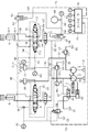
- FIG. 2 is a side view of the shovel loader according to the embodiment of the present invention. It is a figure explaining the hydraulic circuit of the load sensing system of an example.
- FIG. 3 is a diagram illustrating a relationship between an electric signal to a solenoid and a secondary pressure in the electromagnetic proportional pressure reducing valve of the embodiment. It is a figure explaining the relation between the lever operation amount and pilot secondary pressure in the hydraulic remote control valve of an example.
- FIG. 4 is a diagram illustrating a relationship between a lever operation amount and an operation speed (cylinder speed) in an actuator (cylinder) according to the embodiment. It is a figure explaining the relation between the spool stroke and the spool opening area in the direction switching valve of an example.
- FIG. 7 is a diagram illustrating a hydraulic circuit of a conventional load sensing system.
- Embodiments for implementing a fluid circuit according to the present invention will be described below based on embodiments.
- a hydraulic circuit of a shovel loader will be described as an example of a fluid circuit according to an embodiment with reference to FIGS.
- the shovel loader 100 includes a bucket 108 (W2, see FIG. 2) for storing earth and sand, a lift arm 109 (W1, FIG. 2) linked to the bucket 108, and these are hydraulically driven.
- Each has a bucket cylinder 8 and an arm cylinder 9 as actuators to be driven.
- a hydraulic circuit as a fluid circuit of the load sensing system used for the bucket cylinder 8 and the arm cylinder 9 will be described.
- the hydraulic circuit is supplied from a main hydraulic pump 2 and a main hydraulic pump 2 and a pilot hydraulic pump 3 as a variable displacement type pressure fluid source driven by a driving mechanism 1 such as an engine or an electric motor.
- Bucket direction switching valve 6 as a direction switching valve for switching the supply destination of the pressure oil as the pressure fluid to be supplied
- arm direction switching valve 7 as a direction switching valve
- Pressure compensating valves 4 and 5 connected to the source side, bucket cylinder 8 and arm cylinder 9 connected to the actuator side of bucket direction switching valve 6 and arm direction switching valve 7, and pressure supplied from pilot hydraulic pump 3.
- the hydraulic circuit on the side of the bucket cylinder 8 and the hydraulic circuit on the side of the arm cylinder 9 which are fluidly connected in parallel to the main hydraulic pump 2 and the pilot hydraulic pump 3 have substantially the same configuration. The circuit will be described, and the description of the hydraulic circuit on the bucket cylinder 8 side will be omitted.
- the main hydraulic pump 2 and the pilot hydraulic pump 3 are connected to the drive mechanism 1, rotate by the power from the drive mechanism 1, and supply pressure oil through oil paths connected to each other.
- the arm direction switching valve 7 is a normally closed pilot-type directional switching valve of a 5-port 3-position type. In its neutral position, the oil passage 23, the head oil passage 25 of the arm cylinder 9, and the rod oil passage 26 are closed.
- the secondary pressure pilot line 20 is connected to the oil line 24 and the tank 15.
- the oil passage 23 is connected to the head-side oil passage 25 and the secondary pressure pilot line 20, and the rod-side oil passage 26 is connected to the oil passage 24 and the tank 15. Connected to.
- the arm direction switching valve 7 is at the contracted position 7C
- the head-side oil passage 25 is connected to the oil passage 24 and the tank 15, and the oil passage 23 is connected to the rod-side oil passage 26 and the secondary pressure pilot line 20. Connected to.
- the secondary pressure of the arm direction switching valve 7, that is, the actuator side pressure is unloaded through the shuttle valve 16 by the secondary pressure pilot line 20. It is led to the valve 12 and the electromagnetic proportional pressure reducing valve 50.
- the shuttle valve 16 is guided by the secondary pressure pilot line 20 with the actuator side pressure of the bucket direction switching valve 6 and the arm direction switching valve 7, that is, the load pressure of the bucket cylinder 8 and the arm cylinder 9, respectively.
- the shuttle valve 16 selects the highest load pressure of the actuator, which is the higher one of the load pressures of the bucket cylinder 8 and the arm cylinder 9, and guides it to the unload valve 12 and the electromagnetic proportional pressure reducing valve 50. .
- the electromagnetic proportional pressure reducing valve 50 has a pressure characteristic such that the secondary pressure is proportionally reduced in accordance with an increase in the electric signal to the solenoid, and serves as a control unit including an arithmetic circuit.
- the controller 70 is connected by an electric signal line 73, adjusts the pressure reduction amount (opening degree) according to the electric signal from the controller 70, and transfers a part of the maximum load pressure of the actuator selected by the shuttle valve 16 to the tank 15. By releasing, the secondary pressure can be reduced.
- the electromagnetic proportional pressure reducing valve 50 is provided on the primary side of the load sensing valve 41 in the secondary pressure pilot line 20.
- the load sensing valve 41 guides the maximum load pressure of the actuator adjusted by the electromagnetic proportional pressure reducing valve 50 through the secondary pressure pilot line 20, that is, the line on the actuator side of the directional control valve, and branches from the oil line 21.
- the supply pressure of the main hydraulic pump 2, that is, the pressure on the pressure fluid source side of the directional control valve is guided through a primary pressure pilot line 28 as a pilot line branched from 27, and is proportional to the supply pressure of the main hydraulic pump 2.
- the opening degree is adjusted based on the difference between the maximum load pressure of the actuator adjusted by the pressure reducing valve 50, that is, the pressure difference between the pressure fluid source side of the directional switching valve and the actuator side of the directional switching valve adjusted by the electromagnetic proportional pressure reducing valve 50.
- the pump flow rate control pressure can be controlled by the opening degree.
- the swash plate control device 42 operates according to the pressure oil (hereinafter, referred to as a pump flow control pressure) supplied from the load sensing valve 41 to increase or decrease the inclination angle of the swash plate 43 of the main hydraulic pump 2.
- the output of the main hydraulic pump 2 is controlled.
- the pilot primary pressure hydraulic oil discharged from the pilot hydraulic pump 3 is supplied to the arm hydraulic remote control valve 11 through the oil passages 31 and 32.
- the arm hydraulic remote control valve 11 is a variable pressure reducing valve.
- the pilot pressure of the lever is reduced according to the lever operation amount as shown in FIG.
- the next pressure is supplied to the signal ports 7-1 and 7-2 of the arm directional control valve 7 through the signal oil passages 33 and 34, and the spool inside the arm directional control valve 7 strokes to extend or contract the extended position 7E. It switches to position 7C.
- any excess oil that is not supplied from the arm hydraulic remote control valve 11 to the signal ports 7-1 and 7-2 of the arm direction switching valve 7 is all the oil passage 35 and the relief valve. 13.
- the oil is discharged to the tank 15 through the oil passage 36.
- the arm direction switching valve 7 is switched to the extension position 7E, and the pressure oil supplied from the main hydraulic pump 2 is connected to the oil passage 23. Flows into the head chamber 9-1 of the arm cylinder 9 through the head-side oil passage 25, and at the same time, the pressure oil from the rod chamber 9-2 passes through the oil passage 24 connected to the rod-side oil passage 26, and is stored in the tank. It is discharged to 15. Accordingly, the lift arm 109 (W1) can be lifted by extending the arm cylinder 9.
- the arm direction switching valve 7 When the operation lever 11-1 is operated in the contraction direction C, the arm direction switching valve 7 is switched to the contraction position 7C, and the pressure oil supplied from the main hydraulic pump 2 is connected to the oil passage 23 by the rod. Flows into the rod chamber 9-2 of the arm cylinder 9 through the side oil passage 26, and at the same time, pressure oil is discharged from the head chamber 9-1 to the tank 15 through the oil passage 24 connected to the head side oil passage 25. Is done. Thereby, the arm cylinder 9 can be contracted and the lift arm 109 (W1) can be lowered.
- the spool opening for controlling the flow rate flowing from the main hydraulic pump 2 to the arm cylinder 9 changes according to the spool stroke, that is, the lever operation amount, and the operation lever 11-
- the flow rate Qm flowing from the main hydraulic pump 2 to the arm cylinder 9 from the main hydraulic pump 2 by the spool opening area Am in the spool stroke Xm when the lever operation amount of 1 is the maximum Lm (see FIG. 5) is set to be maximum.
- the pressure loss at the spool opening of the arm direction switching valve 7 at the maximum cylinder speed of the arm cylinder 9 is suppressed.
- the pressure compensating valves 4 and 5 provided on the pressure fluid source side of the bucket direction switching valve 6 and the arm direction switching valve 7 are normally open type pressure control valves of a two-port two-position type, and have a secondary pressure pilot line. 20, the load pressures of the bucket cylinder 8 and the arm cylinder 9 are respectively guided, and the bucket direction switching valve 6 and the arm direction switching valve 7 for simultaneously driving the bucket 108 and the lift arm 109 are operated at the same time. Regardless of the magnitude of the load pressure on the bucket cylinder 8 and the arm cylinder 9, a flow rate corresponding to the spool opening area of each directional control valve can flow into the bucket cylinder 8 and the arm cylinder 9.
- the pump flow control pressure is controlled in the load sensing valve 41 such that the differential pressure ⁇ P always becomes the target value ⁇ Pt (constant value) in accordance with the spool opening area of the direction switching valve.
- the output of the main hydraulic pump 2 is controlled by increasing or decreasing the inclination angle of the swash plate 43 of the main hydraulic pump 2 by the swash plate control device 42 based on the pump flow control pressure. That is, as shown in FIG. 6, when the spool opening area is small, the discharge amount from the main hydraulic pump 2 becomes small, and as the spool opening area increases, the main hydraulic pump 2 increases the discharge amount. Is controlled.
- the unload valve 12 connected to the secondary pressure pilot line 20 is set so that the operating pressure is always higher than the supply pressure of the main hydraulic pump 2 by a target value ⁇ Pt.
- a target value ⁇ Pt When the pressure becomes excessive, pressure oil (pressure) is released to the tank 15. Further, the target value ⁇ Pt is set by the urging force of a spring 12-1 built in the unload valve 12.
- a bypass oil passage 63 branches off from the head-side oil passage 25 of the arm cylinder 9, and the accumulator 60 is connected by the bypass oil passage 63, the electromagnetic switching valve 61, and the bypass oil passages 64 and 65.
- the accumulator 60 is connected to the oil passage 22 as a pressure fluid source side flow passage of the direction switching valve by bypass oil passages 65 and 66, an electromagnetic switching valve 62, and a bypass oil passage 67.
- the solenoid-operated switching valves 61 and 62 are two-port two-position type normally closed solenoid-operated switching valves, which are connected to the controller 70 by electric signal lines 71 and 72, respectively, and are closed at the neutral position. It is opened by a signal.
- the electromagnetic switching valves 61 and 62 have built-in check valves, and allow the flow of the pressurized fluid when opened to flow in only one direction.
- the controller 70 includes a signal pressure Pin from a pressure sensor 80 provided in the oil passage 21 and capable of detecting a supply pressure of the main hydraulic pump 2, and an actuator provided in the secondary pressure pilot line 20 and selected by the shuttle valve 16. From the pressure sensor 81 capable of detecting the maximum load pressure to the signal pressure PLS, and from the pressure sensor 82 provided in the bypass oil passage 65 and capable of detecting the pressure in the accumulator 60 to the signal pressure PA and the signal oil passage 33. A signal pressure Px from a pressure sensor 83 that can detect a pilot secondary pressure of the arm hydraulic remote control valve 11 provided, and a signal from a pressure sensor 84 that can detect a pilot secondary pressure of the arm hydraulic remote control valve 11 provided in the signal oil passage 34. The pressures Py are respectively input.
- the arithmetic circuit of the controller 70 calculates the differential pressure ⁇ P of the directional control valve from the signal pressure Pin and the signal pressure PLS, the discharge amount of the accumulator 60 from the signal pressure PA, and the lever of the operation lever 11-1 from the signal pressure Px or the signal pressure Py.
- the operation amount that is, the spool opening of the direction switching valve can be calculated.
- the operation of the accumulator 60 will be described.
- the signal pressure Py is input to the controller 70 from the pressure sensor 84 provided in the signal oil passage 34, and the electromagnetic switching valve 61 is transmitted from the controller 70 through the electric signal line 71. , And the electromagnetic switching valve 61 is opened.
- the pressure is accumulated in the accumulator 60 through 63, 64, 65.
- the signal pressure Px is input to the controller 70 from the pressure sensor 83 provided in the signal oil passage 33, and the electromagnetic switching valve 62 is transmitted from the controller 70 through the electric signal line 72. , An electromagnetic signal is input, and the electromagnetic switching valve 62 is opened.
- the accumulated oil accumulated in the accumulator 60 is discharged from the bypass oil passages 65, 66, and 67 to the oil passage 22, and is regenerated to the head chamber 9-1 of the arm cylinder 9 through the head-side oil passage 25.
- an electric signal is simultaneously input from the controller 70 to the electromagnetic proportional pressure reducing valve 50 through the electric signal line 73, and the pressure reducing amount (opening degree) of the electromagnetic proportional pressure reducing valve 50 is adjusted.
- the maximum load pressure of the actuator guided to the load sensing valve 41 is reduced.
- the load sensing valve 41 the difference between the supply pressure of the main hydraulic pump 2 and the maximum load pressure of the actuator adjusted by the electromagnetic proportional pressure reducing valve 50, that is, the pressure fluid source side of the direction switching valve and the electromagnetic proportional pressure reducing valve 50
- the opening degree is adjusted based on the pressure difference on the actuator side of the directional control valve adjusted by the above
- the pump flow rate control pressure is controlled by the opening degree
- the swash plate control device 42 operates based on the pump flow rate control pressure.
- the output of the main hydraulic pump 2 is reduced by reducing the inclination angle of the swash plate 43 of the main hydraulic pump 2.
- the controller 70 performs electromagnetic proportionality through the electric signal line 73.
- An electric signal is simultaneously input to the pressure reducing valve 50, and the output of the main hydraulic pump 2 is reduced so that the flow rate flowing from the main hydraulic pump 2 into the arm cylinder 9 becomes Qx-QA.
- the hydraulic circuit of the load sensing system can discharge the pressure fluid accumulated in the accumulator 60 to the oil passage 22 as the pressure fluid source side flow path of the direction switching valve.
- a load sensing valve 41 as a discharge amount control mechanism and a swash plate control device based on the pressure in an accumulator 60 by an electromagnetic proportional pressure reducing valve 50 provided in a secondary pressure pilot line 20 for guiding the pressure on the actuator side of the direction switching valve to 41.
- the output of the main hydraulic pump 2 can be supplemented according to the pressure in the accumulator 60 that can be discharged to the pressure fluid source side flow path of the direction switching valve by adjusting the control amount by the control valve 42.
- the control amount by the load sensing valve 41 and the swash plate control device 42 is adjusted by the electromagnetic proportional pressure reducing valve 50 at the same time.
- the output of the main hydraulic pump 2 can be adjusted at an appropriate timing according to the pressure in the accumulator 60, and energy efficiency is good.
- the controller 70 includes a supply pressure of the main hydraulic pump 2 as a pressure fluid source side pressure of the direction switching valve detected by the pressure sensor 80 and an actuator as an actuator side pressure of the direction switching valve detected by the pressure sensor 81. Can be adjusted based on the maximum load pressure and the pressure in the accumulator 60 detected by the pressure sensor 82, so that the pressure difference ⁇ P before and after the directional control valve can be adjusted to the target value. It can be quickly controlled to ⁇ Pt. Further, the controller 70 operates the electromagnetic proportional pressure reducing valve 50 by an electric signal, so that the controller 70 has good responsiveness.
- the pressure reducing valve 50 as the adjusting means can have a simple structure.
- the electromagnetic proportional pressure reducing valve 50 proportionally changes the secondary pressure in response to an increase in the electric signal from the controller 70 based on the pressure in the accumulator 60, that is, the electric signal to the solenoid.
- the control amount by the load sensing valve 41 and the swash plate control device 42 can be finely controlled.
- the bucket direction switching valve 6 and the bucket cylinder 8, the arm direction switching valve 7 and the arm cylinder 9 are fluidly connected in parallel to the main hydraulic pump 2, and the accumulator 60 is connected to the head side oil passage 25 of the arm cylinder 9. Since it is connected to the extended bypass oil passages 63, 64, 65, 66, 67, the pressurized oil stored in the accumulator 60 from the arm cylinder 9 is supplied to the bucket direction switching valve 6 and the bucket cylinder 8, the arm direction switching valve 7 and the arm It can be supplied to both cylinders 9 and the efficiency of the hydraulic circuit is good.
- the electromagnetic switching valve 62 between the accumulator 60 and the oil passage 22 as the pressure fluid source side flow path of the direction switching valve, the differential pressure of the direction switching valve calculated by the arithmetic circuit of the controller 70 is calculated.
- the electromagnetic switching valve 62 is opened and closed as necessary so that the differential pressure ⁇ P of the direction switching valve becomes the target value ⁇ Pt, The discharge amount of the accumulated oil can be controlled.
- the controller 70 compares the signal pressure PA, which is the pressure in the accumulator 60 detected by the pressure sensor 82, with the signal pressure Pin, which is the supply pressure of the main hydraulic pump 2, detected by the pressure sensor 80. Since the valve 62 can be opened and closed, only when the pressure in the accumulator 60 is higher than the supply pressure of the main hydraulic pump 2 (PA> Pin), it is possible to open the electromagnetic switching valve 62 and reliably discharge the accumulator oil from the accumulator 60. it can.
- the opening degree can be adjusted in accordance with the input value of the electric signal from the controller 70 by using the electromagnetic switching valve 62 as a proportional valve, so that the accumulator 60 switches the direction switching valve in accordance with the accumulated pressure of the accumulator 60.
- the discharge amount to the pressure fluid source side flow path may be controlled. According to this, while adjusting the balance between the discharge amount from the main hydraulic pump 2 and the discharge amount from the accumulator 60, the differential pressure ⁇ P across the directional control valve can be controlled to the target value ⁇ Pt. Energy efficient.
- the hydraulic circuit of the shovel loader was described as the fluid circuit of the load sensing system.
- the present invention is not limited to this, and is applied to a fluid circuit of a vehicle other than the shovel loader, a construction machine, an industrial machine, and the like. Is also good.
- the pressure fluid used in the fluid circuit may be a liquid or gas other than oil.
- part of the discharged oil discharged from the inside of the head chamber 9-1 of the arm cylinder 9 to the tank 15 through the head-side oil passage 25 when the arm cylinder 9 is contracted is bypass oil passages 63 and 64. , 65, the pressure is accumulated in the accumulator 60, and the accumulated pressure is regenerated from the oil passage 22 to the arm cylinder 9 when the arm cylinder 9 is extended.
- the present invention is not limited to this.
- the present invention can be applied to any hydraulic circuit that performs pressure accumulation and regeneration using the accumulator 60.
- a part of the return oil at the time of driving the bucket cylinder 8 or braking the traveling hydraulic motor (not shown) of the shovel loader 100 may be used.
- a hydraulic circuit may be configured to accumulate pressure in the accumulator 60 and regenerate the pressure when the hydraulic motor accelerates.
- the mode in which the electromagnetic proportional pressure reducing valve 50 is provided on the primary side of the load sensing valve 41 in the secondary pressure pilot line 20 has been described. May be configured so that the pump flow control pressure controlled by the load sensing valve 41 is reduced by the electromagnetic proportional pressure reducing valve, or independently of the secondary pressure pilot line 20. The output of the main hydraulic pump 2 may be controlled.
- the pressure reducing valve as the adjusting means is a pilot operated pressure reducing valve which is operated by an external hydraulic signal. Is also good.
- the mode in which the hydraulic remote control valve is used to switch the supply destination of the pressure oil supplied from the pilot hydraulic pump 3 has been described.
- an electric signal from the electric remote controller may be directly input to the controller.
- the swash plate control device 42 operates based on the pump flow control pressure controlled by the load sensing valve 41 to increase or decrease the inclination angle of the swash plate 43 of the main hydraulic pump 2 in the above embodiment.
- the mode of controlling the output of the main hydraulic pump 2 has been described.
- the present invention is not limited to this, and the discharge amount control mechanism may be capable of controlling the output of the main hydraulic pump 2 by an electric signal.
- the configuration in which the pressure reducing valve as the adjusting means is provided in the secondary pressure pilot line 20 has been described.
- the pressure increasing mechanism as the adjusting means may be provided in the primary pressure pilot line 28.
- the pressure fluid source side pressure and the actuator side pressure of the direction switching valve may be input by an electric signal instead of the pilot line.
- the accumulator 60 may be provided with a bypass oil passage and an electromagnetic switching valve so that the pressure can be accumulated from the hydraulic circuit on the bucket cylinder 8 side.
- the hydraulic circuit may have only one actuator.
Landscapes
- Engineering & Computer Science (AREA)
- General Engineering & Computer Science (AREA)
- Physics & Mathematics (AREA)
- Fluid Mechanics (AREA)
- Mining & Mineral Resources (AREA)
- Civil Engineering (AREA)
- Structural Engineering (AREA)
- Mechanical Engineering (AREA)
- Chemical & Material Sciences (AREA)
- Analytical Chemistry (AREA)
- Fluid-Pressure Circuits (AREA)
- Operation Control Of Excavators (AREA)
Abstract
Description
圧力流体を供給する圧力流体源と、前記圧力流体源に接続される複数のアクチュエータと、前記圧力流体源から供給される圧力流体の供給先を切り換える方向切換弁と、複数の前記アクチュエータの負荷圧力の内の最大の最高負荷圧力に対し差圧が目標値となるように前記圧力流体源の出力を制御する吐出量制御機構と、を備える流体回路であって、
前記アクチュエータからの戻り流体の一部を蓄圧するアキュムレータを備え、
前記アキュムレータは、蓄圧された圧力流体を前記方向切換弁の圧力流体源側流路に吐出可能であり、
前記アキュムレータの圧力に基づいて前記圧力流体源の制御量を調整する調整手段を備える。
これによれば、複数のアクチュエータの内、最高負荷圧力に対し、圧力流体源の供給圧力を目標差圧分だけ常に高くなるように制御した流体回路において、方向切換弁の圧力流体源側流路に吐出可能なアキュムレータの圧力に応じて圧力流体源の出力を補完できるので、エネルギー効率の高い流体回路が得られる。
これによれば、適正なタイミングで圧力流体源の出力を調整できるため、エネルギー効率がよい。
前記圧力検出手段により検出される圧力に基づいて前記制御部から出力される電気信号により前記調整手段を作動させる。
これによれば、調整手段の応答性が良い。
前記方向切換弁のアクチュエータ側圧力を導く前記パイロット管路に前記調整手段としての減圧弁が設けられている。
これによれば、アクチュエータの最高負荷圧力と、アキュムレータの圧力とによる値によりロードセンシング弁の開度調整を行うことができ、簡単な回路で吐出量制御機構による制御量を調整できる。
これによれば、方向切換弁の圧力流体源側圧力およびアクチュエータ側圧力と、アキュムレータの圧力に基づいて減圧弁における減圧量を調整できるため、方向切換弁の差圧を目標値に迅速に制御することができる。
2 メイン油圧ポンプ(圧力流体源)
3 パイロット油圧ポンプ
4,5 圧力補償弁
6 バケット方向切換弁(方向切換弁)
7 アーム方向切換弁(方向切換弁)
8 バケットシリンダ(アクチュエータ)
9 アームシリンダ(アクチュエータ)
10 バケット油圧リモコン弁
11 アーム油圧リモコン弁
12 アンロード弁
13 リリーフ弁
15 タンク
16 シャトル弁
20 二次圧パイロット管路(パイロット管路)
22 油路(方向切換弁の圧力流体源側流路)
25 ヘッド側油路
26 ロッド側油路
27 一次圧パイロット管路(パイロット管路)
37 アキュムレータ
41 ロードセンシング弁(吐出量制御機構)
42 斜板制御装置(吐出量制御機構)
43 斜板
50 電磁比例減圧弁(調整手段,減圧弁)
60 アキュムレータ
61,62 電磁切換弁
63~67 バイパス油路
70 コントローラ(制御部)
80,81 圧力センサ
82 圧力センサ(圧力検出手段)
100 ショベルローダ
108 バケット
109 リフトアーム
Claims (5)
- 圧力流体を供給する圧力流体源と、前記圧力流体源に接続される複数のアクチュエータと、前記圧力流体源から供給される圧力流体の供給先を切り換える方向切換弁と、複数の前記アクチュエータの負荷圧力の内の最大の最高負荷圧力に対し差圧が目標値となるように前記圧力流体源の出力を制御する吐出量制御機構と、を備える流体回路であって、
前記アクチュエータからの戻り流体の一部を蓄圧するアキュムレータを備え、
前記アキュムレータは、蓄圧された圧力流体を前記方向切換弁の圧力流体源側流路に吐出可能であり、
前記アキュムレータの圧力に基づいて前記圧力流体源の制御量を調整する調整手段を備える流体回路。 - 前記アキュムレータから前記方向切換弁の圧力流体源側流路への圧力流体の吐出時に前記調整手段により前記制御量が調整される請求項1に記載の流体回路。
- 前記アキュムレータの圧力を検出する圧力検出手段と、演算回路を有する制御部を備え、
前記圧力検出手段により検出される圧力に基づいて前記制御部から出力される電気信号により前記調整手段を作動させる請求項1または2に記載の流体回路。 - 前記吐出量制御機構は、パイロット管路により導かれる前記方向切換弁の圧力流体源側圧力とアクチュエータ側圧力の差圧により開度調整を行うロードセンシング弁を備え、
前記方向切換弁のアクチュエータ側圧力を導く前記パイロット管路に前記調整手段としての減圧弁が設けられている請求項1ないし3のいずれかに記載の流体回路。 - 少なくとも前記方向切換弁の圧力流体源側圧力およびアクチュエータ側圧力と、前記アキュムレータの圧力に基づいて前記減圧弁における減圧量を調整できる請求項4に記載の流体回路。
Priority Applications (5)
| Application Number | Priority Date | Filing Date | Title |
|---|---|---|---|
| EP19864296.9A EP3859168B1 (en) | 2018-09-26 | 2019-09-25 | Fluid circuit |
| US17/276,918 US11225983B2 (en) | 2018-09-26 | 2019-09-25 | Fluid circuit |
| CN201980061437.7A CN112703324B (zh) | 2018-09-26 | 2019-09-25 | 流体回路 |
| JP2020549250A JP7404258B2 (ja) | 2018-09-26 | 2019-09-25 | 流体回路 |
| KR1020217008760A KR102535297B1 (ko) | 2018-09-26 | 2019-09-25 | 유체 회로 |
Applications Claiming Priority (2)
| Application Number | Priority Date | Filing Date | Title |
|---|---|---|---|
| JP2018-180825 | 2018-09-26 | ||
| JP2018180825 | 2018-09-26 |
Publications (1)
| Publication Number | Publication Date |
|---|---|
| WO2020067084A1 true WO2020067084A1 (ja) | 2020-04-02 |
Family
ID=69949618
Family Applications (1)
| Application Number | Title | Priority Date | Filing Date |
|---|---|---|---|
| PCT/JP2019/037447 Ceased WO2020067084A1 (ja) | 2018-09-26 | 2019-09-25 | 流体回路 |
Country Status (6)
| Country | Link |
|---|---|
| US (1) | US11225983B2 (ja) |
| EP (1) | EP3859168B1 (ja) |
| JP (1) | JP7404258B2 (ja) |
| KR (1) | KR102535297B1 (ja) |
| CN (1) | CN112703324B (ja) |
| WO (1) | WO2020067084A1 (ja) |
Cited By (1)
| Publication number | Priority date | Publication date | Assignee | Title |
|---|---|---|---|---|
| CN112128175A (zh) * | 2020-08-27 | 2020-12-25 | 中联重科股份有限公司 | 基于夹角检测的工程机械动力调整方法及液压动力系统 |
Families Citing this family (4)
| Publication number | Priority date | Publication date | Assignee | Title |
|---|---|---|---|---|
| KR20220140351A (ko) | 2021-04-09 | 2022-10-18 | 현대두산인프라코어(주) | 건설기계 |
| US11834811B2 (en) * | 2021-10-25 | 2023-12-05 | Cnh Industrial America Llc | System and method for controlling hydraulic pump operation within a work vehicle |
| CN113775592B (zh) * | 2021-11-11 | 2022-01-07 | 太原理工大学 | 数字机械冗余压力补偿流量控制系统 |
| US20250044816A1 (en) * | 2023-07-31 | 2025-02-06 | Hamilton Sundstrand Corporation | Valve systems |
Citations (3)
| Publication number | Priority date | Publication date | Assignee | Title |
|---|---|---|---|---|
| JPH0374605A (ja) | 1989-08-16 | 1991-03-29 | Komatsu Ltd | 作業機シリンダの圧油供給装置 |
| JP2008185182A (ja) * | 2007-01-31 | 2008-08-14 | Shin Caterpillar Mitsubishi Ltd | 作業機械における油圧制御システム |
| JP2008190694A (ja) * | 2007-02-07 | 2008-08-21 | Komatsu Ltd | オートデセル制御機能を備えた制御装置及びその制御方法 |
Family Cites Families (6)
| Publication number | Priority date | Publication date | Assignee | Title |
|---|---|---|---|---|
| DE60113002T2 (de) * | 2000-01-25 | 2006-03-30 | Hitachi Construction Machinery Co., Ltd. | Hydraulische antriebseinrichtung |
| US7905089B2 (en) * | 2007-09-13 | 2011-03-15 | Caterpillar Inc. | Actuator control system implementing adaptive flow control |
| JP5354650B2 (ja) * | 2008-10-22 | 2013-11-27 | キャタピラー エス エー アール エル | 作業機械における油圧制御システム |
| US8997476B2 (en) * | 2012-07-27 | 2015-04-07 | Caterpillar Inc. | Hydraulic energy recovery system |
| DE102014215567A1 (de) * | 2014-08-06 | 2016-02-11 | Robert Bosch Gmbh | Hydrostatischer Antrieb |
| CN105864126B (zh) * | 2016-05-24 | 2018-02-09 | 浙江大学 | 一种节能设计的tbm推进支撑液压系统 |
-
2019
- 2019-09-25 JP JP2020549250A patent/JP7404258B2/ja active Active
- 2019-09-25 KR KR1020217008760A patent/KR102535297B1/ko active Active
- 2019-09-25 US US17/276,918 patent/US11225983B2/en active Active
- 2019-09-25 WO PCT/JP2019/037447 patent/WO2020067084A1/ja not_active Ceased
- 2019-09-25 EP EP19864296.9A patent/EP3859168B1/en active Active
- 2019-09-25 CN CN201980061437.7A patent/CN112703324B/zh active Active
Patent Citations (3)
| Publication number | Priority date | Publication date | Assignee | Title |
|---|---|---|---|---|
| JPH0374605A (ja) | 1989-08-16 | 1991-03-29 | Komatsu Ltd | 作業機シリンダの圧油供給装置 |
| JP2008185182A (ja) * | 2007-01-31 | 2008-08-14 | Shin Caterpillar Mitsubishi Ltd | 作業機械における油圧制御システム |
| JP2008190694A (ja) * | 2007-02-07 | 2008-08-21 | Komatsu Ltd | オートデセル制御機能を備えた制御装置及びその制御方法 |
Non-Patent Citations (1)
| Title |
|---|
| See also references of EP3859168A4 |
Cited By (1)
| Publication number | Priority date | Publication date | Assignee | Title |
|---|---|---|---|---|
| CN112128175A (zh) * | 2020-08-27 | 2020-12-25 | 中联重科股份有限公司 | 基于夹角检测的工程机械动力调整方法及液压动力系统 |
Also Published As
| Publication number | Publication date |
|---|---|
| EP3859168A1 (en) | 2021-08-04 |
| KR20210046752A (ko) | 2021-04-28 |
| EP3859168A4 (en) | 2022-06-22 |
| US20210372088A1 (en) | 2021-12-02 |
| EP3859168B1 (en) | 2023-08-09 |
| CN112703324A (zh) | 2021-04-23 |
| KR102535297B1 (ko) | 2023-05-26 |
| US11225983B2 (en) | 2022-01-18 |
| JPWO2020067084A1 (ja) | 2021-08-30 |
| JP7404258B2 (ja) | 2023-12-25 |
| CN112703324B (zh) | 2023-06-06 |
Similar Documents
| Publication | Publication Date | Title |
|---|---|---|
| JP7404258B2 (ja) | 流体回路 | |
| US9080310B2 (en) | Closed-loop hydraulic system having regeneration configuration | |
| EP3301229B1 (en) | Hydraulic driving device of work machine | |
| US8863509B2 (en) | Meterless hydraulic system having load-holding bypass | |
| JP6467515B2 (ja) | 建設機械 | |
| US20100000209A1 (en) | Hydraulic control system in working machine ( as amended | |
| JP6509651B2 (ja) | 流体回路 | |
| US8944103B2 (en) | Meterless hydraulic system having displacement control valve | |
| US8966892B2 (en) | Meterless hydraulic system having restricted primary makeup | |
| WO2019220954A1 (ja) | 油圧ショベル駆動システム | |
| JP2004346485A (ja) | 油圧駆動装置 | |
| JP2017226492A5 (ja) | ||
| JP2008185182A (ja) | 作業機械における油圧制御システム | |
| CN116412186A (zh) | 背压阀布置结构 | |
| JP2003004003A (ja) | 油圧ショベルの油圧制御回路 | |
| US9835179B2 (en) | Hydraulic valve arrangement | |
| JP6615137B2 (ja) | 建設機械の油圧駆動装置 | |
| US11459729B2 (en) | Hydraulic excavator drive system | |
| JP6605413B2 (ja) | 作業機械の油圧駆動装置 | |
| JP2008202704A (ja) | 建設機械の油圧制御装置 | |
| JP2015031377A (ja) | 油圧駆動装置 | |
| JP4926627B2 (ja) | 電油システム | |
| WO2026105723A1 (ja) | 流体圧回路 | |
| JP4703418B2 (ja) | 油圧アクチュエータ用制御回路 | |
| JPH08151663A (ja) | 平衡錘脱着装置付き油圧ショベル |
Legal Events
| Date | Code | Title | Description |
|---|---|---|---|
| 121 | Ep: the epo has been informed by wipo that ep was designated in this application |
Ref document number: 19864296 Country of ref document: EP Kind code of ref document: A1 |
|
| ENP | Entry into the national phase |
Ref document number: 2020549250 Country of ref document: JP Kind code of ref document: A |
|
| ENP | Entry into the national phase |
Ref document number: 20217008760 Country of ref document: KR Kind code of ref document: A |
|
| NENP | Non-entry into the national phase |
Ref country code: DE |
|
| ENP | Entry into the national phase |
Ref document number: 2019864296 Country of ref document: EP Effective date: 20210426 |