WO2020067425A1 - 活物質、それを用いた正極合剤及び全固体電池 - Google Patents
活物質、それを用いた正極合剤及び全固体電池 Download PDFInfo
- Publication number
- WO2020067425A1 WO2020067425A1 PCT/JP2019/038154 JP2019038154W WO2020067425A1 WO 2020067425 A1 WO2020067425 A1 WO 2020067425A1 JP 2019038154 W JP2019038154 W JP 2019038154W WO 2020067425 A1 WO2020067425 A1 WO 2020067425A1
- Authority
- WO
- WIPO (PCT)
- Prior art keywords
- active material
- positive electrode
- peak
- less
- solid electrolyte
- Prior art date
- Legal status (The legal status is an assumption and is not a legal conclusion. Google has not performed a legal analysis and makes no representation as to the accuracy of the status listed.)
- Ceased
Links
Images


Classifications
-
- C—CHEMISTRY; METALLURGY
- C01—INORGANIC CHEMISTRY
- C01G—COMPOUNDS CONTAINING METALS NOT COVERED BY SUBCLASSES C01D OR C01F
- C01G53/00—Compounds of nickel
- C01G53/40—Complex oxides containing nickel and at least one other metal element
- C01G53/42—Complex oxides containing nickel and at least one other metal element containing alkali metals, e.g. LiNiO2
- C01G53/44—Complex oxides containing nickel and at least one other metal element containing alkali metals, e.g. LiNiO2 containing manganese
- C01G53/50—Complex oxides containing nickel and at least one other metal element containing alkali metals, e.g. LiNiO2 containing manganese of the type (MnO2)n-, e.g. Li(NixMn1-x)O2 or Li(MyNixMn1-x-y)O2
-
- H—ELECTRICITY
- H01—ELECTRIC ELEMENTS
- H01M—PROCESSES OR MEANS, e.g. BATTERIES, FOR THE DIRECT CONVERSION OF CHEMICAL ENERGY INTO ELECTRICAL ENERGY
- H01M10/00—Secondary cells; Manufacture thereof
- H01M10/05—Accumulators with non-aqueous electrolyte
- H01M10/052—Li-accumulators
-
- H—ELECTRICITY
- H01—ELECTRIC ELEMENTS
- H01M—PROCESSES OR MEANS, e.g. BATTERIES, FOR THE DIRECT CONVERSION OF CHEMICAL ENERGY INTO ELECTRICAL ENERGY
- H01M10/00—Secondary cells; Manufacture thereof
- H01M10/05—Accumulators with non-aqueous electrolyte
- H01M10/056—Accumulators with non-aqueous electrolyte characterised by the materials used as electrolytes, e.g. mixed inorganic/organic electrolytes
- H01M10/0561—Accumulators with non-aqueous electrolyte characterised by the materials used as electrolytes, e.g. mixed inorganic/organic electrolytes the electrolyte being constituted of inorganic materials only
- H01M10/0562—Solid materials
-
- H—ELECTRICITY
- H01—ELECTRIC ELEMENTS
- H01M—PROCESSES OR MEANS, e.g. BATTERIES, FOR THE DIRECT CONVERSION OF CHEMICAL ENERGY INTO ELECTRICAL ENERGY
- H01M10/00—Secondary cells; Manufacture thereof
- H01M10/05—Accumulators with non-aqueous electrolyte
- H01M10/058—Construction or manufacture
- H01M10/0585—Construction or manufacture of accumulators having only flat construction elements, i.e. flat positive electrodes, flat negative electrodes and flat separators
-
- H—ELECTRICITY
- H01—ELECTRIC ELEMENTS
- H01M—PROCESSES OR MEANS, e.g. BATTERIES, FOR THE DIRECT CONVERSION OF CHEMICAL ENERGY INTO ELECTRICAL ENERGY
- H01M4/00—Electrodes
- H01M4/02—Electrodes composed of, or comprising, active material
- H01M4/13—Electrodes for accumulators with non-aqueous electrolyte, e.g. for lithium-accumulators; Processes of manufacture thereof
- H01M4/131—Electrodes based on mixed oxides or hydroxides, or on mixtures of oxides or hydroxides, e.g. LiCoOx
-
- H—ELECTRICITY
- H01—ELECTRIC ELEMENTS
- H01M—PROCESSES OR MEANS, e.g. BATTERIES, FOR THE DIRECT CONVERSION OF CHEMICAL ENERGY INTO ELECTRICAL ENERGY
- H01M4/00—Electrodes
- H01M4/02—Electrodes composed of, or comprising, active material
- H01M4/36—Selection of substances as active materials, active masses, active liquids
- H01M4/362—Composites
- H01M4/366—Composites as layered products
-
- H—ELECTRICITY
- H01—ELECTRIC ELEMENTS
- H01M—PROCESSES OR MEANS, e.g. BATTERIES, FOR THE DIRECT CONVERSION OF CHEMICAL ENERGY INTO ELECTRICAL ENERGY
- H01M4/00—Electrodes
- H01M4/02—Electrodes composed of, or comprising, active material
- H01M4/36—Selection of substances as active materials, active masses, active liquids
- H01M4/48—Selection of substances as active materials, active masses, active liquids of inorganic oxides or hydroxides
- H01M4/483—Selection of substances as active materials, active masses, active liquids of inorganic oxides or hydroxides for non-aqueous cells
-
- H—ELECTRICITY
- H01—ELECTRIC ELEMENTS
- H01M—PROCESSES OR MEANS, e.g. BATTERIES, FOR THE DIRECT CONVERSION OF CHEMICAL ENERGY INTO ELECTRICAL ENERGY
- H01M4/00—Electrodes
- H01M4/02—Electrodes composed of, or comprising, active material
- H01M4/36—Selection of substances as active materials, active masses, active liquids
- H01M4/48—Selection of substances as active materials, active masses, active liquids of inorganic oxides or hydroxides
- H01M4/50—Selection of substances as active materials, active masses, active liquids of inorganic oxides or hydroxides of manganese
- H01M4/505—Selection of substances as active materials, active masses, active liquids of inorganic oxides or hydroxides of manganese of mixed oxides or hydroxides containing manganese for inserting or intercalating light metals, e.g. LiMn2O4 or LiMn2OxFy
-
- H—ELECTRICITY
- H01—ELECTRIC ELEMENTS
- H01M—PROCESSES OR MEANS, e.g. BATTERIES, FOR THE DIRECT CONVERSION OF CHEMICAL ENERGY INTO ELECTRICAL ENERGY
- H01M4/00—Electrodes
- H01M4/02—Electrodes composed of, or comprising, active material
- H01M4/36—Selection of substances as active materials, active masses, active liquids
- H01M4/48—Selection of substances as active materials, active masses, active liquids of inorganic oxides or hydroxides
- H01M4/52—Selection of substances as active materials, active masses, active liquids of inorganic oxides or hydroxides of nickel, cobalt or iron
- H01M4/525—Selection of substances as active materials, active masses, active liquids of inorganic oxides or hydroxides of nickel, cobalt or iron of mixed oxides or hydroxides containing iron, cobalt or nickel for inserting or intercalating light metals, e.g. LiNiO2, LiCoO2 or LiCoOxFy
-
- H—ELECTRICITY
- H01—ELECTRIC ELEMENTS
- H01M—PROCESSES OR MEANS, e.g. BATTERIES, FOR THE DIRECT CONVERSION OF CHEMICAL ENERGY INTO ELECTRICAL ENERGY
- H01M4/00—Electrodes
- H01M4/02—Electrodes composed of, or comprising, active material
- H01M4/62—Selection of inactive substances as ingredients for active masses, e.g. binders, fillers
-
- C—CHEMISTRY; METALLURGY
- C01—INORGANIC CHEMISTRY
- C01P—INDEXING SCHEME RELATING TO STRUCTURAL AND PHYSICAL ASPECTS OF SOLID INORGANIC COMPOUNDS
- C01P2002/00—Crystal-structural characteristics
- C01P2002/30—Three-dimensional structures
- C01P2002/32—Three-dimensional structures spinel-type (AB2O4)
-
- C—CHEMISTRY; METALLURGY
- C01—INORGANIC CHEMISTRY
- C01P—INDEXING SCHEME RELATING TO STRUCTURAL AND PHYSICAL ASPECTS OF SOLID INORGANIC COMPOUNDS
- C01P2004/00—Particle morphology
- C01P2004/60—Particles characterised by their size
- C01P2004/61—Micrometer sized, i.e. from 1-100 micrometer
-
- C—CHEMISTRY; METALLURGY
- C01—INORGANIC CHEMISTRY
- C01P—INDEXING SCHEME RELATING TO STRUCTURAL AND PHYSICAL ASPECTS OF SOLID INORGANIC COMPOUNDS
- C01P2004/00—Particle morphology
- C01P2004/80—Particles consisting of a mixture of two or more inorganic phases
- C01P2004/82—Particles consisting of a mixture of two or more inorganic phases two phases having the same anion, e.g. both oxidic phases
- C01P2004/84—Particles consisting of a mixture of two or more inorganic phases two phases having the same anion, e.g. both oxidic phases one phase coated with the other
-
- C—CHEMISTRY; METALLURGY
- C01—INORGANIC CHEMISTRY
- C01P—INDEXING SCHEME RELATING TO STRUCTURAL AND PHYSICAL ASPECTS OF SOLID INORGANIC COMPOUNDS
- C01P2006/00—Physical properties of inorganic compounds
- C01P2006/12—Surface area
-
- C—CHEMISTRY; METALLURGY
- C01—INORGANIC CHEMISTRY
- C01P—INDEXING SCHEME RELATING TO STRUCTURAL AND PHYSICAL ASPECTS OF SOLID INORGANIC COMPOUNDS
- C01P2006/00—Physical properties of inorganic compounds
- C01P2006/80—Compositional purity
-
- C—CHEMISTRY; METALLURGY
- C01—INORGANIC CHEMISTRY
- C01P—INDEXING SCHEME RELATING TO STRUCTURAL AND PHYSICAL ASPECTS OF SOLID INORGANIC COMPOUNDS
- C01P2006/00—Physical properties of inorganic compounds
- C01P2006/80—Compositional purity
- C01P2006/82—Compositional purity water content
-
- H—ELECTRICITY
- H01—ELECTRIC ELEMENTS
- H01M—PROCESSES OR MEANS, e.g. BATTERIES, FOR THE DIRECT CONVERSION OF CHEMICAL ENERGY INTO ELECTRICAL ENERGY
- H01M4/00—Electrodes
- H01M4/02—Electrodes composed of, or comprising, active material
- H01M2004/026—Electrodes composed of, or comprising, active material characterised by the polarity
- H01M2004/028—Positive electrodes
-
- H—ELECTRICITY
- H01—ELECTRIC ELEMENTS
- H01M—PROCESSES OR MEANS, e.g. BATTERIES, FOR THE DIRECT CONVERSION OF CHEMICAL ENERGY INTO ELECTRICAL ENERGY
- H01M2300/00—Electrolytes
- H01M2300/0017—Non-aqueous electrolytes
- H01M2300/0065—Solid electrolytes
- H01M2300/0068—Solid electrolytes inorganic
-
- Y—GENERAL TAGGING OF NEW TECHNOLOGICAL DEVELOPMENTS; GENERAL TAGGING OF CROSS-SECTIONAL TECHNOLOGIES SPANNING OVER SEVERAL SECTIONS OF THE IPC; TECHNICAL SUBJECTS COVERED BY FORMER USPC CROSS-REFERENCE ART COLLECTIONS [XRACs] AND DIGESTS
- Y02—TECHNOLOGIES OR APPLICATIONS FOR MITIGATION OR ADAPTATION AGAINST CLIMATE CHANGE
- Y02E—REDUCTION OF GREENHOUSE GAS [GHG] EMISSIONS, RELATED TO ENERGY GENERATION, TRANSMISSION OR DISTRIBUTION
- Y02E60/00—Enabling technologies; Technologies with a potential or indirect contribution to GHG emissions mitigation
- Y02E60/10—Energy storage using batteries
-
- Y—GENERAL TAGGING OF NEW TECHNOLOGICAL DEVELOPMENTS; GENERAL TAGGING OF CROSS-SECTIONAL TECHNOLOGIES SPANNING OVER SEVERAL SECTIONS OF THE IPC; TECHNICAL SUBJECTS COVERED BY FORMER USPC CROSS-REFERENCE ART COLLECTIONS [XRACs] AND DIGESTS
- Y02—TECHNOLOGIES OR APPLICATIONS FOR MITIGATION OR ADAPTATION AGAINST CLIMATE CHANGE
- Y02P—CLIMATE CHANGE MITIGATION TECHNOLOGIES IN THE PRODUCTION OR PROCESSING OF GOODS
- Y02P70/00—Climate change mitigation technologies in the production process for final industrial or consumer products
- Y02P70/50—Manufacturing or production processes characterised by the final manufactured product
Definitions
- the present invention relates to an active material used for an all-solid-state battery.
- Lithium ion secondary batteries are widely used as power sources for portable electronic devices such as notebook computers and mobile phones because of their high energy density and easy downsizing and weight reduction. Recently, development of a high-output, high-capacity lithium-ion secondary battery to be mounted on an electric vehicle, a hybrid electric vehicle, and the like has been advanced.
- an object of the present invention is to provide an active material capable of reducing interface resistance with a sulfide solid electrolyte and improving battery performance.
- the present invention in a radial distribution function obtained by measuring an X-ray absorption fine structure, at least one peak is observed in a range of 0.145 nm or more and 0.185 nm or less, and a peak of 0.28 nm or more and 0.31 nm or less is observed.
- the present invention provides an active material in which at least one peak is observed in a range and which is used for an all-solid-state battery.
- an active material capable of reducing interface resistance with a sulfide solid electrolyte and improving battery performance.
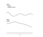
- FIG. 1 is a radial distribution function obtained by measuring an X-ray absorption fine structure measured for an oxide containing lithium and niobium.
- FIG. 2 is a radial distribution function obtained by measuring the X-ray absorption fine structure measured on the positive electrode active material obtained in the example.
- FIG. 3 is a radial distribution function obtained by measuring the X-ray absorption fine structure measured on the positive electrode active materials obtained in Examples and Comparative Examples.
- FIG. 4 is a graph showing the interfacial resistance in batteries obtained using the positive electrode active materials obtained in Examples and Comparative Examples.
- FIG. 5 is a graph showing a method of determining whether or not a peak exists in a radial distribution function obtained by measuring an X-ray absorption fine structure measured for the positive electrode active material of Example 1.
- the present invention relates to an active material used for an all solid state battery.
- the active material of the present invention has at least one peak in a radial distribution function obtained by measuring an X-ray absorption fine structure (hereinafter also referred to as “XAFS”) in a range of 0.145 nm to 0.185 nm. At least one peak is observed in the range from 0.28 nm to 0.31 nm.
- XAFS X-ray absorption fine structure
- the active material of the present invention at least one peak is observed in a range of 0.145 nm or more and 0.185 nm or less in a radial distribution function obtained by XAFS measurement.
- the peak position is specified by the position of the peak apex. The definition of the peak will be described later.
- the peak position observed in the present invention may be, for example, 0.148 nm or more, 0.151 nm or more, or 0.154 nm or more. On the other hand, the peak position may be, for example, 0.180 nm or less.
- the number of peaks observed in the above range may be at least one, for example, only one, or two or more.
- the active material of the present invention at least one peak is observed in a range from 0.28 nm to 0.31 nm.
- the peak position observed in the present invention may be, for example, 0.285 nm or more.
- the peak position may be, for example, 0.310 nm or less, or 0.308 nm or less.
- the active material of the present invention preferably has core material particles and a coating layer disposed on the surface of the core material particles.
- the coating layer in the active material of the present invention has an oxide containing Li and Nb.
- an oxide having a specific chemical structure is used in the present invention.
- this oxide is referred to as “LiNbO” for convenience.
- LiNbO used in the present invention is characterized in that a peak is observed at a specific interatomic distance in a radial distribution function obtained by measuring an X-ray absorption fine structure (hereinafter, also referred to as “XAFS”) for an active material. Attached. Specifically, the horizontal axis of the radial distribution function shown in FIG.
- the active material of the present invention suppresses an increase in interfacial resistance with the sulfide solid electrolyte by including LiNbO, whose peak is observed in the above-described predetermined range, in the coating layer. As a result, the battery performance can be improved.
- a peak is observed in the radial distribution function means that the radial distribution function may include an upwardly convex portion or a shoulder portion.
- the presence or absence of a peak was determined by differentiating the radial distribution function twice using Origin 9.1 (manufactured by Light @ Stone). For example, in Example 1 to be described later, as shown in FIG.
- a peak observed in a range of 0.145 nm or more and 0.185 nm or less has a minimum value by differentiating the radial distribution function twice. . From this, it can be said that in Example 1, a peak is observed in the range of 0.145 nm or more and 0.185 nm or less.
- LiNbO suitably used in the present invention has a peak at a predetermined position of a specific interatomic distance in a radial distribution function obtained from XAFS.
- conventionally known Li-Nb-O-based compounds do not have a peak at a predetermined position defined in the present invention in the radial distribution function obtained from XAFS.
- LiNbO 3 which is a kind of a conventionally known Li—Nb—O-based compound, has a range of 0.145 nm to 0.185 nm and a range of 0.28 nm to 0.31 nm. No peak is observed.
- Li 3 NbO 4 which is another kind of the conventionally known Li—Nb—O-based compound, has a peak in the range of 0.28 nm to 0.31 nm, but has a peak of 0.145 nm to 0%. No peak is observed in the range of .185 nm or less.
- LiNbO suitably used in the present invention has a novel structure that has not been known so far.
- XAFS is a technique for analyzing an absorption spectrum obtained by irradiating a substance with X-rays.
- an absorption spectrum obtained by irradiating a substance with X-rays a steep rise peculiar to an element contained in the substance, that is, an absorption edge is observed.
- the fine structure appearing at about ⁇ 50 eV in the vicinity of the absorption edge is called XANES (X-ray-Absorption NearEdge Structure).
- a vibration structure appearing at about 1000 eV on the high energy side from the absorption edge is referred to as EXAFS (Extended X-ray Absorption Fine Structure).
- a region obtained by combining XANES and EXAFS is called XAFS.
- XAFS XAFS-based atomic distance, coordination number
- a chemical state valence, coordination structure
- XAFS is a nondestructive measurement method and a measurement method capable of obtaining information on the outermost surface of a substance
- the active material itself of the present invention can be used as a measurement target, and information on a coating layer of the active material can be used. Can be obtained.
- the operation is performed according to the following procedure.
- Sample preparation After the sample is ground in an agate mortar, it is mixed with boron nitride powder to form a tablet having a diameter of 10 mm and a thickness of about 1 mm.
- the amount of the sample and the amount of boron nitride are appropriately optimized according to the concentration of Nb contained in the sample to be measured and the absorption coefficients of the niobium compound and the compounds constituting the core material particles.
- a radial distribution function obtained by Fourier-transforming the EXAFS spectrum will be described. "Athena" (Demeter ver. 0.9.25) is used as analysis software. First, after reading the XAFS spectrum with the same software, a Pre-edge region (a region of about -150 to -45 eV from the absorption edge) as a background absorption and a Post-edge region (a region of about 150 to 1300 eV from the absorption edge) And the XAFS spectrum is normalized. Next, fitting is performed with a spline curve to extract an EXAFS spectrum ( ⁇ (k)).
- the water content of the active material of the present invention is adjusted to a certain range. Specifically, if the moisture content of the active material is excessively high, the interface resistance between the active material and the sulfide solid electrolyte may increase.
- the active material may have a moisture content B (mass ppm) up to 110 ° C. measured by the Karl Fischer method of, for example, 50 ppm or more, or 150 ppm or more. And may be 200 ppm or more.
- the water content B may be, for example, 8000 ppm or less, 5000 ppm or less, 3500 ppm or less, or 3000 ppm or less.
- the active material may have a moisture content B (mass ppm) up to 110 ° C. measured by the Karl Fischer method of, for example, 1 ppm or more, or 50 ppm.
- the water content B may be, for example, 8000 ppm or less, 5000 ppm or less, 3500 ppm or less, 2000 ppm or less, or 1000 ppm or less.
- the active material When the core material particles in the active material contain a layered compound, the active material has a moisture content (mass ppm) up to 250 ° C. measured by the Karl Fischer method of, for example, 350 ppm or more, or 380 ppm or more. And may be 400 ppm or more. On the other hand, the water content may be, for example, 10000 ppm or less, 6000 ppm or less, or 3000 ppm or less. When the core material particles in the active material include a spinel-type compound, the active material may have a moisture content (mass ppm) up to 250 ° C.
- the moisture content may be, for example, 10000 ppm or less, 6000 ppm or less, 3500 ppm or less, or 3000 ppm or less.
- Active material of the present invention has a BET specific surface area A (m 2 / g) is, may also be 0.2 m 2 / g or more, it may also be 0.3 m 2 / g or more, 0.4 m 2 / G or more, and may be 0.5 m 2 / g or more. 5.0 m 2 / g or less, 3.0 m 2 / g or less, 2.5 m 2 / g or less, or 2.0 m 2 / g or less Good.
- the active material of the present invention has a value of B / A, which is a ratio of a water content B (mass ppm) up to 110 ° C. measured by the Karl Fischer method with respect to a BET specific surface area A (m 2 / g), for example, It may be 1 or more, 20 or more, 40 or more, 50 or more, 100 or more, or 200 or more.
- the value of B / A may be, for example, 8000 or less, 5000 or less, 3500 or less, 2000 or less, or 1000 or less. , Less than 1000.
- B / A it is advantageous to select an appropriate range for the value of B / A according to the type of the material constituting the active material from the viewpoint of further reducing the interface resistance between the active material and the sulfide solid electrolyte. is there. More specifically, when the core material particles are composed of a layered compound such as lithium cobalt oxide (LiCoO 2 ) and nickel cobalt lithium manganate (Li (Ni, Co, Mn) O 2 ), B / A May be, for example, 50 or more, 100 or more, or 200 or more. On the other hand, the value of B / A may be, for example, 8000 or less, 5000 or less, or 2000 or less.
- the value of B / A is, for example, 5 or more.
- the number may be 20 or more, may be 50 or more, may be 100 or more, may be 150 or more, or may be 200 or more.
- the value of B / A may be 8000 or less, 5000 or less, or 2000 or less.
- the reason for dividing the moisture content B measured by the Karl Fischer method by the BET specific surface area A with respect to the moisture content of the active material is to standardize the moisture content of the active material.
- the procedure for measuring the moisture content by the Karl Fischer method is as follows. That is, the measurement sample is heated to 110 ° C. or 250 ° C. using a Karl Fischer moisture meter, and the amount of released moisture (ppm) is measured. The measurement is performed in an argon atmosphere. For example, 899 Coulometer (manufactured by Metrohm) and 860 KF Thermoprep (manufactured by Metrohm) are used as measuring devices.
- the BET specific surface area is determined by a BET one-point method using a fully automatic specific surface area measuring device Macsorb (manufactured by Mountech Co., Ltd.) as a measuring device. Specifically, the sample is weighed in a glass cell (standard cell), and after replacing the inside of the glass cell with nitrogen gas, heat treatment is performed at 250 ° C. for 15 minutes in the nitrogen gas atmosphere. Thereafter, cooling is performed for 4 minutes while flowing a mixed gas of nitrogen and helium. After cooling, the sample (powder) is measured by the BET one-point method. Note that a mixed gas of 30% nitrogen and 70% helium is used as the adsorption gas at the time of cooling and measurement.
- the value of B / A of the active material can be adjusted by, for example, producing the active material by a method described below, and then heat-treating the active material or drying by heating under vacuum.
- the active material of the present invention preferably has a predetermined interface resistance.
- the interface resistance of the active material is preferably, for example, 40 ⁇ or less, preferably 30 ⁇ or less, 25 ⁇ or less, and more preferably 15 ⁇ or less. Note that the measurement of the interface resistance can be performed, for example, in the same manner as in the examples described later, and thus description thereof is omitted.
- the ratio of LiNbO contained in the active material is expressed as a ratio of the mass of niobium to the mass of the active material for convenience, it may be, for example, 0.01% by mass or more, or 0.1% by mass or more. It may be 0.5% by mass or more. On the other hand, the proportion may be, for example, 10% by mass or less, 5% by mass or less, or 3% by mass or less.
- the ratio can be determined by ICP emission spectroscopy on a solution in which the active material is dissolved. The ratio can be controlled by adjusting the amount of the niobium source compound used in the method for producing an active material described below.
- the amount of carbonate ions is preferably within a predetermined range. Thereby, the interface resistance between the active material and the sulfide solid electrolyte can be effectively reduced.
- the amount of carbonate ions present on the surface of the active material is preferably less than 2.0% by mass, more preferably less than 1.5% by mass, more preferably less than 1.0% by mass, and more preferably less than 2.0% by mass based on the active material. It is preferably less than 0.5% by mass, more preferably less than 0.35% by mass, more preferably less than 0.30% by mass, more preferably less than 0.20% by mass.
- the amount of carbonate ions present on the surface of the active material is preferably less than 0.35% by mass, more preferably less than 0.30% by mass, based on the active material. More preferably, it is less than 0.20% by mass.
- the amount of carbonate ions present on the surface of the active material is preferably less than 2.0% by mass relative to the active material, and particularly less than 1.5% by mass. Among them, it is preferably less than 1.0% by mass, more preferably less than 0.5% by mass, more preferably less than 0.3% by mass.
- a method of reducing the amount of carbonate ions present on the surface of the active material for example, a method of firing in an atmosphere containing no carbon dioxide, such as a nitrogen atmosphere or an oxygen atmosphere, may be mentioned.
- Examples of the method for measuring the amount of carbonate ions include the following methods. That is, 0.48 g of the active material is put into 48 ml of pure water, stirred for 5 minutes, and then filtered. The amount of carbonate ions can be determined by performing ion chromatography measurement on the liquid from which carbonate ions have been extracted in this manner and quantifying CO 3 2- . The measurement was performed at 35 ° C. using DIONEX ICS-2000 manufactured by Thermo Fisher Scientific, using DIONEX IonPac AS17-C for the column and potassium hydroxide for the carrier liquid (eluent). It can be carried out.
- the active material has a volume cumulative particle diameter D 50 at a cumulative volume of 50% by volume measured by a laser diffraction scattering particle size distribution method, for example, 20 ⁇ m or less, particularly less than 15 ⁇ m, more than 1 ⁇ m to less than 10 ⁇ m, and more preferably more than 2 ⁇ m to 8 ⁇ m or less. It is even more preferred.
- D 50 is 20 ⁇ m or less, for example in the case of using an active material in the positive electrode mixture, can ensure good contact with the sulfide solid electrolyte in the positive electrode mixture, a lithium ion utilization in the active material Can be enhanced.
- D 50 is greater than 1 [mu] m, it is possible to prevent the increase in slurry viscosity aggregated particles.
- the adjustment of the operating conditions of the spray drying granulation method or tumbling fluidized granulation method or may be performed adjustment of crushing conditions, these adjustments methods
- the present invention is not limited to this.
- the active material of the present invention which relates to an active material having core particles and a coating layer, the core particles and the coating layer constituting the active material will be described.
- the core material particles are not particularly limited as long as they function as an active material.
- the core material particles may include, for example, a lithium metal composite oxide.
- a lithium metal composite oxide a known lithium metal composite oxide can be used.
- the metal in the lithium metal composite oxide for example, both a transition element and a typical element can be used, and a transition element is preferably used.
- the lithium metal composite oxide include lithium cobaltate (LiCoO 2 ), lithium nickelate (LiNiO 2 ), lithium nickel cobalt manganate (Li (Ni, Co, Mn) O 2 ), and lithium manganate (LiMn 2).
- lithium transition metal oxides such as lithium nickel manganate (LiNi 0.5 Mn 1.5 O 4 ).
- the structure of these oxides is not particularly limited, and may be, for example, a layered rock salt type compound or a spinel type compound.
- the core material particles of the spinel-type compound are particles containing Li, Mn, O, and one or more other elements. Further, as additional elements, Na, Mg, Al, P, K, Ca, Ti, V, Cr, Fe, Co, Ni, Cu, Ga, Y, Zr, Nb, Mo, In, Ta, W, Re, and It is possible to add a combination of one or more elements selected from the group consisting of Ce.
- the core material particles of the spinel-type compound are particles containing Li, Mn, and O and one or more other elements, and at least one of the above-mentioned “one or more elements” is Ni. , Co, and Fe.
- the amount of the M1 element contained in the core material particles is, for example, preferably 7% by mass or more, more preferably 9% by mass or more, and particularly preferably 11% by mass, based on all the elements in the core material particles. It is preferable that it is above.
- the amount of the MI element contained in the core material particles is preferably, for example, 35% by mass or less, preferably 30% by mass or less, and more preferably 25% by mass, based on all the elements in the core material particles. When these elements are contained, an operating potential of 4.5 V or more is mainly exhibited at the metal Li reference potential.
- the M2 element may be included in addition to the M1 element.
- M2 element examples include Na, Mg, Al, P, K, Ca, Ti, V, Cr, Fe, Co, Ni, Cu, Ga, Y, and Zr. , Nb, Mo, In, Ta, W, Re, and Ce.
- M2 elements it is preferable to be selected from the group consisting of Na, Mg, Al, P, K, Ca, Ti, Fe, Co, Ni, Zr, Nb, Mo and W.
- the content of the lithium metal composite oxide in the core particles may be, for example, 80% by mass or more, 90% by mass or more, or 95% by mass. % Or more.
- the core material particles may be composed only of the lithium metal composite oxide. As the lithium metal composite oxide, only one type may be used, or two or more types may be used in combination.
- the coating layer disposed on the surface of the core material particles may cover the surface of the core material particles evenly, or partially cover the core material particles so that a part of the surface of the core material particles is exposed. May be coated. That is, it is preferable that the coating layer covers the surface of the core material particles to the extent that the effects of the present invention can be obtained. Specifically, the coverage of the coating layer may be, for example, 50% or more, 70% or more, 90% or more, or 100%.
- the material constituting the coating layer is a material that can be coated on the core material particles, and when the above-described XAFS measurement is performed on the active material of the present invention, a peak is obtained at a predetermined position in the obtained radial distribution function. Any material that can be observed may be used. Examples of such a material include an oxide containing a lithium (Li) element and a niobium (Nb) element.
- the oxide containing the Li element and the Nb element may contain, for example, only the Li element and the Nb element as metal elements, or may further contain another metal element. Examples of other metal elements include a titanium (Ti) element and a zirconium (Zr) element.
- the types of elements contained in the oxide constituting the coating layer are determined by element mapping for the positive electrode active material, X-ray photoelectron spectroscopy (XPS), scanning transmission electron microscope (STEM), and energy dispersion as necessary. It can be confirmed by observing the surface of the core material particles by combining the pattern X-ray analysis (EDS) or by Auger electron spectroscopy. The type of element can also be identified by ICP emission spectroscopy on a solution in which the positive electrode active material is dissolved.
- the oxide constituting the coating layer contains a metal element other than the Li element and the Nb element
- the ratio between the Nb element and the other metal element is represented by a molar ratio, and the ratio other than the Li element and the Nb element is expressed. Is preferably, for example, 0.5 or less, more preferably 0.3 or less, further preferably 0.2 or less, and more preferably 0.1 or less. Is more preferred.
- the core material particles used in the present invention are, for example, weighed and mixed with raw materials such as a lithium salt compound, a manganese salt compound, a nickel salt compound and a cobalt salt compound, and wet-pulverized. After pulverizing with a machine or the like, it can be obtained by granulating, calcining, heat-treating as necessary, crushing under preferable conditions, and further classifying as necessary. Instead of this method, a basic substance such as sodium hydroxide is added to an aqueous solution containing a manganese salt compound, a nickel salt compound, and a cobalt salt compound to precipitate a metal composite hydroxide. Core material particles can also be obtained by mixing and firing with a lithium salt compound.
- lithium salt compound as a raw material examples include lithium hydroxide (LiOH), lithium carbonate (Li 2 CO 3 ), lithium nitrate (LiNO 3 ), LiOH ⁇ H 2 O, lithium oxide (Li 2 O), and lithium fatty acid. And lithium halides. Among them, lithium hydroxide, carbonate and nitrate are preferable.
- Manganese salt compounds include, for example, manganese carbonate, manganese nitrate, manganese chloride, manganese dioxide and the like. Among them, manganese carbonate and manganese dioxide are preferable, and electrolytic manganese dioxide obtained by an electrolytic method is particularly preferable.
- the nickel salt compound include nickel carbonate, nickel nitrate, nickel chloride, nickel oxyhydroxide, nickel hydroxide and nickel oxide, and among them, nickel carbonate, nickel hydroxide and nickel oxide are preferable.
- Examples of the cobalt salt compound include basic cobalt carbonate, cobalt nitrate, cobalt chloride, cobalt oxyhydroxide, cobalt hydroxide, and cobalt oxide. Among them, basic cobalt carbonate, cobalt hydroxide, cobalt oxide and oxywater Cobalt oxide is preferred.
- the obtained slurry is preferably pulverized by a wet pulverizer, but may be dry pulverized.
- the above-mentioned granulation method may be either a wet method or a dry method as long as the various raw materials pulverized in the previous step are dispersed in the granulated particles without being separated.
- a wet method for example, there are an extrusion granulation method, a tumbling granulation method, a fluidized granulation method, a mixed granulation method, a spray drying granulation method, a press molding granulation method, and a flake granulation method using a roll and the like.
- the drying may be performed by a known drying method such as a spray heat drying method, a hot air drying method, a vacuum drying method, and a freeze drying method. Among them, the spray heat drying method is preferable.
- the spray heat drying method is preferably performed using a hot spray dryer (spray dryer).
- the firing is performed in a firing furnace under an air atmosphere, an oxygen gas atmosphere, an atmosphere in which the oxygen partial pressure is adjusted, a carbon dioxide gas atmosphere, or another atmosphere, for example, at a temperature higher than 700 ° C. and lower than 1000 ° C.
- the temperature is preferably maintained at 750 ° C. or more and 1000 ° C. or less, more preferably 800 ° C. or more and 950 ° C. or less, for 0.5 hour or more and 30 hours or less.
- the type of the firing furnace is not particularly limited.
- the firing can be performed using a rotary kiln, a stationary furnace, or another firing furnace.
- the heat treatment after firing is preferably performed when the crystal structure needs to be adjusted.
- the heat treatment is performed in an oxidizing atmosphere such as an air atmosphere, an oxygen gas atmosphere, or an atmosphere in which the oxygen partial pressure is adjusted.
- a treatment liquid containing a lithium source compound and a niobium source compound is brought into contact with the core material particles.
- the lithium source compound for example, lithium hydroxide, lithium sulfate, lithium chloride and the like can be used.
- the niobium source compound for example, ammonium peroxoniobate can be used.
- a treatment liquid obtained by dissolving these compounds in water and core material particles are mixed to form a slurry, and the slurry is heated at 90 ° C.
- LiNbO has a property of easily adsorbing on the surface of the positive electrode active material
- a coating layer containing LiNbO can be formed on the surface of the core material particles.
- a treatment liquid obtained by heating a lithium raw material and ammonium peroxoniobate to 90 ° C. or higher it may be sprayed on the core material particles, or LiNbO is purified from the treatment liquid heated to 90 ° C. or higher and used for coating. You may. Thereafter, crushing and heat treatment are performed as necessary.
- the amount of the treatment liquid used is such that the proportion of niobium in the active material is, for example, preferably 0.01% by mass or more, more preferably 0.1% by mass or more, and particularly preferably 0.5% by mass or more. It is preferred that On the other hand, the ratio is, for example, preferably 10% by mass or less, more preferably 5% by mass or less, and particularly preferably 3% by mass or less.
- the concentration of the processing solution is not particularly limited.
- a coating layer containing LiNbO having a specific structure By drying the slurry, a coating layer containing LiNbO having a specific structure can be obtained.
- a spray dry granulation method or a tumbling fluidized bed granulation method can be used.
- heat treatment may be performed as needed. Specifically, heat treatment is preferably performed in an atmosphere of oxygen, nitrogen, or argon containing as little carbon dioxide gas as possible.
- the drying and heat treatment temperature can be preferably from 105 ° C to 400 ° C, more preferably from 150 ° C to 400 ° C, and still more preferably from 200 ° C to 380 ° C. More preferably, the temperature can be set to 205 ° C or higher and 350 ° C or lower.
- the heat treatment time is preferably from 1 hour to 20 hours, more preferably from 1 hour to 15 hours, even more preferably from 1 hour to 10 hours.
- the active material thus obtained may be subjected to, for example, heat treatment again, or may be subjected to vacuum heating and drying in order to further reduce the moisture content.
- the active material of the present invention can be usually used as a positive electrode active material.
- the active material of the present invention is used for an all-solid-state battery.
- the active material of the present invention is advantageously used in an all-solid battery including a sulfide solid electrolyte as a solid electrolyte.
- the effect of the present invention can be enjoyed by the presence of the contact portion between the active material of the present invention and the sulfide solid electrolyte.
- “there is a contact portion between the active material and the sulfide solid electrolyte” means that (a) the sulfide solid electrolyte is contained in the positive electrode mixture (in this case, even if the solid electrolyte layer is non-sulfide, Yes), (a) the sulfide solid electrolyte is not contained in the positive electrode mixture and the sulfide solid electrolyte is contained in the solid electrolyte layer, and (c) the sulfide solid electrolyte is contained in the positive electrode mixture. And that the solid electrolyte layer contains a sulfide solid electrolyte.
- the positive electrode mixture of the present invention contains an active material and a sulfide solid electrolyte.
- the active material contained in the positive electrode mixture can be the same as the content described in the section “A. Active Material”, and thus the description is omitted here.
- the sulfide solid electrolyte used in the present invention can be the same as the sulfide solid electrolyte used in general all-solid-state batteries.
- the sulfide solid electrolyte in the present invention may be, for example, one containing Li and S and having lithium ion conductivity.
- the sulfide solid electrolyte may be any of a crystalline material, glass ceramic, and glass.
- the sulfide solid electrolyte may have an Argyrodite-type crystal phase. Examples of such a sulfide solid electrolyte include Li 2 S—P 2 S 5 , Li 2 S—P 2 S 5 —LiHa (“Ha” indicates one or more halogen elements), and Li 2 S.
- the active material contained in the positive electrode mixture of the present invention may be the active material of the present invention alone, or may be used in combination with another active material.
- the other active material include particles made of the above-described known lithium transition metal composite oxide, and the particles may or may not have a coating layer.
- the active material of the present invention preferably contains 50 mol% or more, more preferably 70% or more, of the whole active material.
- the proportion of the sulfide solid electrolyte in the positive electrode mixture of the present invention is typically 10% by mass or more and 50% by mass or less.
- the positive electrode mixture may contain other materials such as a conductive auxiliary agent and a binder as necessary.
- a positive electrode layer can be prepared by mixing the positive electrode mixture and a solvent to prepare a paste, applying the paste on a current collector such as an aluminum foil, and drying.
- the all-solid-state battery of the present invention includes a positive electrode layer, a negative electrode layer, and a solid electrolyte layer, and the positive electrode layer includes the above-described positive electrode mixture.
- the all-solid-state battery of the present invention can be manufactured, for example, by stacking three layers of the positive electrode layer, the solid electrolyte layer, and the negative electrode layer manufactured as described above and press-molding them.
- the negative electrode active material used for the negative electrode layer can be the same as the negative electrode active material used for a general all solid state battery.
- a material capable of inserting and extracting lithium ions for example, a carbon material, a known material such as a silicon oxide compound such as silicon and Si—O, a tin compound, and lithium titanate can be used.
- the carbon material include polyacrylonitrile, phenol resin, phenol novolak resin, sintered organic polymer compounds such as cellulose, artificial graphite and natural graphite.
- the negative electrode layer can be produced in the same manner as the production of the positive electrode layer except that such a negative electrode active material is used.
- Treatment liquid A 2A Production of Active Material (Positive Electrode Active Material) 3.68 g of LiOH.H 2 O and 24 g of ammonium peroxoniobate were dissolved in 2000 mL of water to prepare a treatment liquid. This treatment liquid is referred to as treatment liquid A.
- the treatment liquid A was added to 200 g of the core material particles obtained in the above (1), and heated at 90 ° C. or higher. By heating at 90 ° C. or higher, the lithium source and ammonium peroxoniobate react in the solution. Thereby, LiNbO having a property of being easily adsorbed on the surface of the core material particles is generated on the surface of the core material particles.
- Example 2 In (1A), the particle diameter of the core particles was changed. In (2A), the amount of LiOH.H 2 O added at the time of preparing the treatment liquid A was changed to 1.7 g, and the amount of ammonium peroxoniobate was changed to 11.1 g. Except for these, a cathode active material was obtained in the same manner as in Example 1. This sample had one peak in the range of 0.145 nm to 0.185 nm and one peak in the range of 0.28 nm to 0.31 nm.
- Example 3 A positive electrode active material was obtained in the same manner as in Example 1, except that the conditions shown in Table 1 were employed. This sample had one peak in the range of 0.145 nm to 0.185 nm and one peak in the range of 0.28 nm to 0.31 nm.
- Example 5 A positive electrode active material was obtained in the same manner as in Example 1 except that vacuum drying was further added at 120 ° C. for 2 hours in (2A). This sample had one peak in the range of 0.145 nm to 0.185 nm and one peak in the range of 0.28 nm to 0.31 nm.
- Example 6 A positive electrode active material was obtained in the same manner as in Example 3 except that vacuum drying was further added at 120 ° C. for 2 hours in (2A). This sample had one peak in the range of 0.145 nm to 0.185 nm and one peak in the range of 0.28 nm to 0.31 nm.
- Example 7 A positive electrode active material was obtained in the same manner as in Example 4 except that LiOH.H 2 O was not added in (2A) and heat treatment was not performed. This sample had one peak in the range of 0.145 nm to 0.185 nm and one peak in the range of 0.28 nm to 0.31 nm.
- Example 8 A positive electrode active material was obtained in the same manner as in Example 4 except that no heat treatment was performed in (2A). This sample had one peak in the range of 0.145 nm to 0.185 nm and one peak in the range of 0.28 nm to 0.31 nm.
- Example 9 In (2A), a positive electrode active material was obtained in the same manner as in Example 4, except that the amount of LiOH.H 2 O was changed to 20.3 g, the water was changed to 1000 mL, and heat treatment was not performed. This sample had one peak in the range of 0.145 nm to 0.185 nm and one peak in the range of 0.28 nm to 0.31 nm.
- Example 10 Production of Core Material Particles Lithium carbonate, electrolytic manganese dioxide, nickel hydroxide, and titanium oxide were each weighed. These materials were put into ion-exchanged water and pulverized by a wet pulverizer to obtain a pulverized slurry. The obtained pulverized slurry was subjected to thermal spray drying to obtain granulated powder. The obtained granulated powder was fired at 900 ° C. for 37 hours in an air atmosphere using a stationary electric furnace. The fired product was crushed and heat-treated at 750 ° C. for 37 hours. Thereafter, the resultant was washed with water and filtered, and dried at 500 ° C. for 7 hours.
- the crushed material was placed in a tubular standing furnace, and heat-treated at 725 ° C. for 5 hours while flowing oxygen at a supply rate of 0.5 L / min into the standing furnace.
- the heat-treated product was classified with a sieve having a mesh size of 53 ⁇ m, and core material particles made of a lithium manganese-containing composite oxide were collected under the sieve.
- This core material particle was identified by XRD measurement to be a spinel-type lithium manganese-containing composite oxide.
- this lithium manganese-containing composite oxide was 4.2% by mass of Li, 13.0% by mass of Ni, 42.5% by mass of Mn, and 5.3% by mass of Ti.
- LiNbO of the present invention is generated by heating the lithium raw material and ammonium peroxoniobate in a solution by heating at 90 ° C. or more, so that the LiNbO of the present invention has a property of being easily adsorbed on the surface of the positive electrode active material. It is. 0.346 g of purified LiNbO was dissolved in 9.9 mL of water, added to the mixed solution, and further mixed. The mixed solution was decanted and dried at 120 ° C, and then heat-treated at 350 ° C for 2 hours to obtain a positive electrode active material. This sample had one peak in the range of 0.145 nm to 0.185 nm and one peak in the range of 0.28 nm to 0.31 nm.
- a positive electrode active material was obtained by heat treatment at 500 ° C. for 5 hours in an atmosphere. This sample had no peak in the range of 0.145 nm or more and 0.185 nm or less, and had one peak in the range of 0.28 nm or more and 0.31 nm or less.
- Comparative Example 2 This comparative example is an example in which the core material particles obtained in (1B) above were used as the positive electrode active material.
- positive electrode layers were produced according to a conventional method. Specifically, the obtained positive electrode active material, Li 5.8 PS 4.8 Cl 1.2 which is a sulfide solid electrolyte (Argyrodite type solid electrolyte), and VGCF (registered trademark) which is a conductive additive were used. The mixture was mixed at a mass ratio of 80: 17: 3 to prepare a positive electrode mixture, which was used as a positive electrode layer. In addition, graphite was used as a negative electrode active material, and a negative electrode layer was formed according to a conventional method.
- Li 5.8 PS 4.8 Cl 1.2 which is a sulfide solid electrolyte (Argyrodite type solid electrolyte)
- VGCF registered trademark
- the positive electrode layer, the sulfide solid electrolyte layer (Li 5.8 PS 4.8 Cl 1.2 which is an Argyrodite type solid electrolyte), and the negative electrode layer were stacked in this order and pressure-molded to produce an all-solid-state battery.
- This all-solid-state battery was charged to 50% of its discharge capacity after charging and discharging in the initial third cycle, and then subjected to AC impedance measurement.
- the interface resistance value ( ⁇ ) was calculated from the intersection with the horizontal axis in the Cole-Cole plot, which is a complex impedance plane plot of the measurement results.
- FIG. 4 shows the results.
- a positive electrode layer was produced according to a conventional method.
- the obtained cathode active material Li 5.4 PS 4.4 Cl 0.8 Br 0.8 that is a sulfide solid electrolyte (Argyrodite type solid electrolyte), and VGCF (a conductive auxiliary agent) (Registered trademark) at a mass ratio of 60:30:10 to prepare a positive electrode mixture, which was used as a positive electrode layer.
- graphite was used as a negative electrode active material, and a negative electrode layer was formed according to a conventional method.
- a positive electrode layer Li 5.4 PS 4.4 Cl 0.8 Br 0.8 which is an Argyrodite type solid electrolyte
- a negative electrode layer is stacked in this order and pressure-molded to form an all-solid-state battery.
- This all-solid-state battery was charged to 5.0 V at a current value of 0.1 C, further charged at a constant voltage until the current value reached 0.025 C, and then discharged to 3.0 V at 0.1 C.
- Table 2 shows the initial discharge capacity.
- the positive electrode active material of each example has one peak observed in the range of 0.145 nm to 0.185 nm and 0.28 nm to 0.31 nm. It can be seen that one peak is observed in the range.
- the positive electrode active material of Comparative Example 1 a peak was observed in the range of 0.28 nm to 0.31 nm, but no peak was observed in the range of 0.145 nm to 0.185 nm. .
- Tables 1 and 2 it can be seen that the all-solid-state battery using the positive electrode active material obtained in each of the examples has a reduced interfacial resistance.
- the all-solid-state battery using the positive electrode active material obtained in Comparative Example 1 has a higher interfacial resistance than each of the examples.
- the all-solid-state battery using the positive electrode active material obtained in Comparative Example 2 has a lower discharge capacity than Example 10 and a high interface resistance. From the above, it was found that battery performance could be improved by using the active material of the present invention.
- a treatment liquid was prepared by dissolving 31 g of LiOH.H 2 O and 6.4 g of ammonium peroxoniobate in 450 mL of water. This treatment liquid is referred to as treatment liquid A.
- a treatment liquid was prepared by dissolving 32 g of lithium sulfate in 2000 mL of water. This treatment liquid is referred to as treatment liquid B.
- Li [Ni 0.4 Mn 1.4 Ti 0.2 ] O 4 which is a spinel type compound was used as the core material particles. After 100 g of core material particles were added to the treatment liquid A and heated at 90 ° C. or higher, a residue C was obtained by solid-liquid separation.
- the residue C was mixed with 900 mL of the treatment liquid and B, and the residue D was obtained by solid-liquid separation.
- the residue D was mixed with 900 mL of the treatment liquid B, and the residue E was obtained by solid-liquid separation.
- the residue E was dried at 120 ° C. for 2 hours to obtain a positive electrode active material.
- the reason for heating at 90 ° C. or higher is that the lithium raw material and ammonium peroxoniobate react in a solution to generate the LiNbO of the present invention, and the LiNbO of the present invention is easily adsorbed on the surface of the positive electrode active material. To have.
- the obtained positive electrode active material one peak was observed in the range of 0.145 nm or more and 0.185 nm or less, and one peak was observed in the range of 0.28 nm or more and 0.31 nm or less.
- the value of B / A, the particle size D 50 , the BET specific surface area, the water content (110 ° C. and 250 ° C.), and the discharge capacity were measured in the same manner as in Example 1. Table 3 shows the results.
- a treatment liquid was prepared by dissolving 62 g of LiOH.H 2 O and 6.4 g of ammonium peroxoniobate in 450 mL of water. This treatment liquid is referred to as treatment liquid A.
- a treatment liquid was prepared by dissolving 32 g of lithium sulfate in 2000 mL of water. This treatment liquid is referred to as treatment liquid B.
- Li [Ni 0.4 Mn 1.4 Ti 0.2 ] O 4 which is a spinel type compound was used as the core material particles. After 100 g of core material particles were added to the treatment liquid A and heated at 90 ° C. or higher, a residue C was obtained by solid-liquid separation.
- the residue C was mixed with 900 mL of the treatment liquid B, and the residue D was obtained by solid-liquid separation.
- the residue D is mixed with 900 mL of the treatment liquid B, and the residue E is obtained by solid-liquid separation.
- the residue E was dried at 200 ° C. for 2 hours to obtain a positive electrode active material.
- the reason for heating at 90 ° C. or higher is the same as in Example 12.
- one peak was observed in the range of 0.145 nm or more and 0.185 nm or less, and one peak was observed in the range of 0.28 nm or more and 0.31 nm or less.
- a treatment liquid was prepared by dissolving 62 g of LiOH.H 2 O and 6.2 g of ammonium peroxoniobate in 450 mL of water. This treatment liquid is referred to as treatment liquid A.
- a treatment liquid was prepared by dissolving 32 g of lithium sulfate in 2000 mL of water. This treatment liquid is referred to as treatment liquid B.
- Li [Ni 0.4 Mn 1.4 Ti 0.2 ] O 4 which is a spinel type compound was used as the core material particles. After 100 g of core material particles were added to the treatment liquid A and heated at 90 ° C. or higher, a residue C was obtained by solid-liquid separation.
- the residue C was mixed with 900 mL of the treatment liquid B, and the residue D was obtained by solid-liquid separation.
- the residue D is mixed with 900 mL of the treatment liquid B, and the residue E is obtained by solid-liquid separation.
- the residue E was dried at 200 ° C. for 2 hours to obtain a positive electrode active material.
- the reason for heating at 90 ° C. or higher is the same as in Example 12.
- one peak was observed in the range of 0.145 nm or more and 0.185 nm or less, and one peak was observed in the range of 0.28 nm or more and 0.31 nm or less.
Landscapes
- Chemical & Material Sciences (AREA)
- Electrochemistry (AREA)
- General Chemical & Material Sciences (AREA)
- Chemical Kinetics & Catalysis (AREA)
- Inorganic Chemistry (AREA)
- Engineering & Computer Science (AREA)
- Manufacturing & Machinery (AREA)
- Composite Materials (AREA)
- Physics & Mathematics (AREA)
- Condensed Matter Physics & Semiconductors (AREA)
- General Physics & Mathematics (AREA)
- Materials Engineering (AREA)
- Organic Chemistry (AREA)
- Battery Electrode And Active Subsutance (AREA)
- Secondary Cells (AREA)
Abstract
Description
本発明の活物質は、X線吸収微細構造(以下「XAFS」ともいう。)の測定によって得られる動径分布関数において、0.145nm以上0.185nm以下の範囲にピークが少なくとも1つ観察されるとともに、0.28nm以上0.31nm以下の範囲にピークが少なくとも1つ観察される。
本発明において観察されるピーク位置は、例えば、0.148nm以上であってもよく、0.151nm以上であってもよく、0.154nm以上であってもよい。一方、前記ピーク位置は、例えば、0.180nm以下であってもよい。
前記範囲に観察されるピークは、少なくとも1つであればよく、例えば1つのみであってもよく、2つ以上であってもよい。これとともに本発明の活物質は、0.28nm以上0.31nm以下の範囲にピークが少なくとも1つ観察される。本発明において観察されるピーク位置は、例えば、0.285nm以上であってもよい。一方、前記ピーク位置は、例えば、0.310nm以下であってもよく、0.308nm以下であってもよい。
ここで、本発明の活物質における被覆層は、Li及びNbを含む酸化物を有する。Li及びNbを含む酸化物には種々のものが知られているところ、本発明においては、特定の化学構造を有する酸化物を用いる。以下、この酸化物のことを便宜的に「LiNbO」と表記する。本発明で用いられるLiNbOは、活物質に対するX線吸収微細構造(以下「XAFS」ともいう。)の測定によって得られる動径分布関数において、特定の原子間距離にピークが観察されることによって特徴付けられる。具体的には、図1に示す動径分布関数の横軸は、ニオブ原子の位置を基準とした原子間距離を示している。縦軸は、ニオブの周囲に位置する原子の存在確率を示している。0.145nm以上0.185nm以下の範囲に観察されるピークは、ニオブ原子と酸素原子との距離に相当するものであり、0.28nm以上0.31nm以下の範囲に観察されるピークはニオブ原子どうしの距離に相当するものである。XAFSから得られる動径分布関数において、上述した所定の範囲にピークが観察されるLiNbOを被覆層に含有させることで、本発明の活物質は、硫化物固体電解質との界面抵抗の増加を抑制し、結果として電池性能の向上を図ることが可能である。
試料調製
試料をメノウ乳鉢で粉砕した後、窒化ホウ素粉末と混合し、直径10mm、厚さ約1mmの錠剤にする。測定する試料に含まれるNbの濃度や、ニオブ化合物及び芯材粒子を構成する化合物の吸収係数に応じて、試料と窒化ホウ素の分量を適宜最適にする。
・実験施設:SPring-8
・実験ステーション:BL14b2
・分光器 :モノクロメータSi(311)
・高次光除去:Rhコートミラー2.4mrad×2枚
・入射X線サイズ:縦1mm×横5mm(試料前スリットサイズ)
・測定法:透過法
・検出器:イオンチャンバー
・測定吸収端 :Nb-K吸収端(18986eV)
各入射X線エネルギー(E、x軸)において、I0、Itを測定し、次式により、X線吸光度(y軸)を求め、x軸-y軸でプロットすることにより、XAFSスペクトルを得た。
X線吸光度μt=-ln(It/I0)
EXAFSスペクトルをフーリエ変換して得られる動径分布関数について説明する。
解析ソフトウェアとして「Athena」(Demeter ver.0.9.25)を用いる。
初めに、同ソフトにてXAFSスペクトルを読み込んだ後に、バックグラウンド吸収であるPre-edge領域(吸収端から-150~-45eV程度の領域)と、Post-edge領域(吸収端から150~1300eV程度の領域)とをフィッティングして、XAFSスペクトルを規格化する。次にEXAFSスペクトル(χ(k))を抽出するために、スプライン曲線でフィッティングを行う。同ソフトでの解析においてスプライン曲線のフィッティングに用いたパラメータは以下の値である。
・Rbkg=1
・Spline range in k:1~15
・Spline clamps low:None、high:None
・k-weight=3
・Plotting k-weights : 3
最後にEXAFSスペクトル(χ(k))をフーリエ変換して、動径分布関数を示すスペクトルを得る。同ソフトでのフーリエ変換のパラメータは、以下の値を用いた。
・k-range:3.5~11.5
・dk:1
・window:Hanning
・arbitrary k-weight:1
・phase correction:未使用
活物質における芯材粒子がスピネル型化合物を含む場合、該活物質は、カールフィッシャー法によって測定された110℃までの水分率B(質量ppm)は、例えば、1ppm以上であってもよく、50ppm以上であってもよく、100ppm以上であってもよく、200ppm以上であってもよい。一方、前記水分率Bは、例えば、8000ppm以下であってもよく、5000ppm以下であってもよく、3500ppm以下であってもよく、2000ppm以下であってもよく、1000ppm以下であってもよい。
また、活物質における芯材粒子がスピネル型化合物を含む場合、該活物質は、カールフィッシャー法によって測定された250℃までの水分率(質量ppm)が、例えば、100ppm以上であってもよく、150ppm以上であってもよく、200ppm以上であってもよく、250ppm以上であってもよく、300ppm以上であってもよく、350ppm以上であってもよく、380ppm以上であってもよく、400ppm以上であってもよい。一方、前記水分率は、例えば、10000ppm以下であってもよく、6000ppm以下であってもよく、3500ppm以下であってもよく、3000ppm以下であってもよい。
上述したB/Aの値は、活物質を構成する物質の種類に応じて、適切な範囲を選定することが、活物質と硫化物固体電解質との界面抵抗を一層低減させるといった観点から有利である。
詳細には、芯材粒子が、コバルト酸リチウム(LiCoO2)やニッケルコバルトマンガン酸リチウム(Li(Ni,Co,Mn)O2)などの層状化合物から構成されている場合には、B/Aの値は、例えば、50以上であってもよく、100以上であってもよく、200以上であってもよい。一方、前記B/Aの値は、例えば、8000以下であってもよく、5000以下であってもよく、2000以下であってもよい。
また、芯材粒子が、ニッケルマンガン酸リチウム(LiNi0.5Mn1.5O4)などのスピネル型化合物から構成される場合には、B/Aの値は、例えば、5以上であってもよく、20以上であってもよく、50以上であってもよく、100以上であってもよく、150以上であってもよく、200以上であってもよい。一方、前記B/Aの値は、8000以下であってもよく、5000以下であってもよく、2000以下であってもよい。
一方、BET比表面積は、測定装置として全自動比表面積測定装置Macsorb(株式会社マウンテック製)を用い、BET1点法によって求める。具体的には、サンプルをガラスセル(標準セル)に秤量し、窒素ガスでガラスセル内を置換した後、前記窒素ガス雰囲気中で250℃15分間、熱処理する。その後、窒素・ヘリウム混合ガスを流しながら、4分間冷却を行う。冷却後、サンプル(粉体)をBET1点法にて測定する。なお、冷却時及び測定時の吸着ガスは、窒素30%:ヘリウム70%の混合ガスを用いる。
芯材粒子が層状化合物を含む場合、活物質の表面に存在する炭酸イオンの量は、活物質に対して0.35質量%未満であることが好ましく、中でも0.30質量%未満、その中でも0.20質量%未満であることが更に好ましい。
一方、芯材粒子がスピネル型化合物を含む場合、活物質の表面に存在する炭酸イオンの量は、活物質に対して2.0質量%未満であることが好ましく、中でも1.5質量%未満、その中でも1.0質量%未満、更にその中でも0.5質量%未満、更にその中でも0.3質量%未満であることが好ましい。
活物質の表面に存在する炭酸イオンの量を低下させる方法としては、例えば、窒素雰囲気下や酸素雰囲気下などの二酸化炭素を含まない雰囲気で焼成する方法が挙げられる。
なお、測定装置には、サーモフィッシャーサイエンティフィック社製 DIONEX ICS-2000を用い、カラムにDIONEX IonPac AS17-C、キャリア液(溶離液)に水酸化カリウムを用い、35℃の条件下で測定を行うことができる。
芯材粒子は、活物質として機能するものであればよく、特に限定されない。芯材粒子は、例えば、リチウム金属複合酸化物を含んでいてもよい。リチウム金属複合酸化物としては、公知のリチウム金属複合酸化物を用いることができる。リチウム金属複合酸化物における金属としては、例えば遷移元素及び典型元素の双方を用いることができ、好ましくは遷移元素が用いられる。リチウム金属複合酸化物としては、例えば、コバルト酸リチウム(LiCoO2)、ニッケル酸リチウム(LiNiO2)、ニッケルコバルトマンガン酸リチウム(Li(Ni,Co,Mn)O2)、マンガン酸リチウム(LiMn2O4)、及びニッケルマンガン酸リチウム(LiNi0.5Mn1.5O4)などのリチウム遷移金属酸化物が挙げられる。これらの酸化物の構造は、特に制限されるものではなく、例えば層状岩塩型化合物であってもよく、あるいはスピネル型化合物であってもよい。
スピネル型化合物の芯材粒子は、Li、Mn及びOとこれら以外の1種類以上の元素を含む粒子である。また、添加元素として、Na、Mg、Al、P、K、Ca、Ti、V、Cr、Fe、Co、Ni、Cu、Ga、Y、Zr、Nb、Mo、In、Ta、W、Re及びCeからなる群から選択される1種以上の元素の組み合わせで添加することが可能である。この中でもNa、Mg、Al、P、K、Ca、Ti、Fe、Co、Ni、Zr、Nb、Mo及びWからなる群から選択されるのが好ましい。
更に、下記のとおり、添加元素種・添加元素量を選定することで、主に金属Li基準電位で、4.5V以上の作動電位を発現することができる。すなわち、スピネル型化合物の芯材粒子を、Li、Mn及びOとこれら以外の1種類以上の元素を含む粒子とし、前記の「これら以外の1種類以上の元素」のうち、少なくとも1元素がNi、Co、Feからなる群から選択される元素M1とすることができる。芯材粒子に含まれるM1元素の量は、芯材粒子中の全元素に対して、例えば7質量%以上であることが好ましく、中でも9質量%以上であることが好ましく、その中でも11質量%以上であることが好ましい。一方、芯材粒子に含まれるMI元素の量は、芯材粒子中の全元素に対して、例えば35質量%以下が好ましく、30質量%以下が好ましく、25質量%が好ましい。これらの元素が含まれると、主に金属Li基準電位で、4.5V以上の作動電位を発現する。M1元素以外にもM2元素を含んでいてもよく、M2元素としては、Na、Mg、Al、P、K、Ca、Ti、V、Cr、Fe、Co、Ni、Cu、Ga、Y、Zr、Nb、Mo、In、Ta、W、Re及びCeからなる群から選択される1種以上の元素の組み合わせからであればよい。前記のM2元素の中でもNa、Mg、Al、P、K、Ca、Ti、Fe、Co、Ni、Zr、Nb、Mo及びWからなる群から選択されるのが好ましい。
芯材粒子の表面に配置される被覆層は、芯材粒子の表面を満遍なく被覆していてもよく、あるいは芯材粒子の表面の一部が露出するように、部分的に芯材粒子の表面を被覆していてもよい。すなわち、被覆層は、本発明の効果が得られる程度に芯材粒子の表面を被覆することが好ましい。具体的には、被覆層の被覆率は、例えば、50%以上であってもよく、70%以上であってもよく、90%以上であってもよく、100%であってもよい。
(1)芯材粒子の形成
本発明で用いる芯材粒子は、例えばリチウム塩化合物、マンガン塩化合物、ニッケル塩化合物及びコバルト塩化合物などの原料を秤量して混合し、湿式粉砕機等で粉砕した後、造粒し、焼成し、必要に応じて熱処理し、好ましい条件で解砕し、更に必要に応じて分級して得ることができる。この方法に代えて、マンガン塩化合物、ニッケル塩化合物及びコバルト塩化合物を含む水溶液に水酸化ナトリウムなどの塩基性物質を添加して金属複合水酸化物を沈殿させ、次いで該金属複合水酸化物とリチウム塩化合物とを混合して焼成することでも、芯材粒子を得ることができる。
ニッケル塩化合物としては、例えば、炭酸ニッケル、硝酸ニッケル、塩化ニッケル、オキシ水酸化ニッケル、水酸化ニッケル及び酸化ニッケル等が挙げられ、中でも炭酸ニッケル、水酸化ニッケル及び酸化ニッケルが好ましい。
コバルト塩化合物としては、例えば、塩基性炭酸コバルト、硝酸コバルト、塩化コバルト、オキシ水酸化コバルト、水酸化コバルト及び酸化コバルト等が挙げられ、中でも塩基性炭酸コバルト、水酸化コバルト、酸化コバルト及びオキシ水酸化コバルトが好ましい。
前記のようにして得られた芯材粒子の表面に被覆層を形成する方法としては、リチウム源化合物及びニオブ源化合物を含有する処理液と芯材粒子とを接触させればよい。リチウム源化合物としては、例えば水酸化リチウム、硫酸リチウム、塩化リチウムなどを用いることができる。ニオブ源化合物としては、例えばペルオキソニオブ酸アンモニウム、などを用いることができる。これらの化合物を水に溶解した処理液と芯材粒子とを混合してスラリーとし、該スラリーを90℃以上で加熱することによりリチウム原料とペルオキソニオブ酸アンモニウムが溶液内で反応することにより、LiNbOが生成する。LiNbOは正極活物質の表面に吸着しやすい性質を持つため、該スラリーを乾燥させることにより、芯材粒子の表面にLiNbOを含んで構成された被覆層を形成することができる。リチウム原料とペルオキソニオブ酸アンモニウムを90℃以上に加熱した処理液を用いて、それを芯材粒子に噴霧してもよいし、90℃以上に加熱した処理液からLiNbOを精製して被覆に用いてもよい。その後、必要に応じて解砕及び熱処理を行う。
本発明の活物質は、通常、正極活物質として用いることができる。また、本発明の活物質は、全固体電池に用いられるものである。特に本発明の活物質は、固体電解質として硫化物固体電解質を含む全固体電池に用いられることが有利である。全固体電池において、本発明の活物質と、硫化物固体電解質との接触部分が存在することにより、本発明の効果を享受することができる。ここで「活物質と、硫化物固体電解質との接触部分が存在する」とは、(ア)正極合剤中に硫化物固体電解質を含有させること(この場合、固体電解質層は非硫化物でも可。)、(イ)正極合剤中に硫化物固体電解質を含有させず、固体電解質層に硫化物固体電解質を含有させること、及び(ウ)正極合剤中に硫化物固体電解質を含有させ、且つ固体電解質層に硫化物固体電解質を含有させることのいずれかを意味する。
本発明の正極合剤は、活物質と、硫化物固体電解質とを含む。なお、正極合剤に含まれる活物質については、前記「A.活物質」の項に記載した内容と同様とすることができるため、ここでの記載は省略する。
本発明の全固体電池は、正極層、負極層、及び固体電解質層を備え、前記正極層が、上述した正極合剤を含む。
(1A)芯材粒子の製造
硫酸ニッケルと硫酸コバルトと硫酸マンガンとを溶解した水溶液に、水酸化ナトリウムを供給し、共沈法によって金属複合水酸化物を作製した。この金属複合水酸化物におけるニッケル、コバルト及びマンガンのモル比は、Ni:Co:Mn=0.6:0.2:0.2であった。この金属複合水酸化物を炭酸リチウムと混合し、静置式電気炉を用いて大気下で720℃、5時間仮焼成した後、大気下で905℃、22時間本焼成してリチウム金属複合酸化物を得た。このリチウム金属複合酸化物を乳鉢で解砕し、次いで目開き53μmの篩で分級し、篩下のリチウム金属複合酸化物粉体からなる芯材粒子を回収した。芯材粒子は層状岩塩型化合物であり、ニッケル、コバルト及びマンガンのモル比は、前記金属複合水酸化物と同様に、Ni:Co:Mn=0.6:0.2:0.2であった。
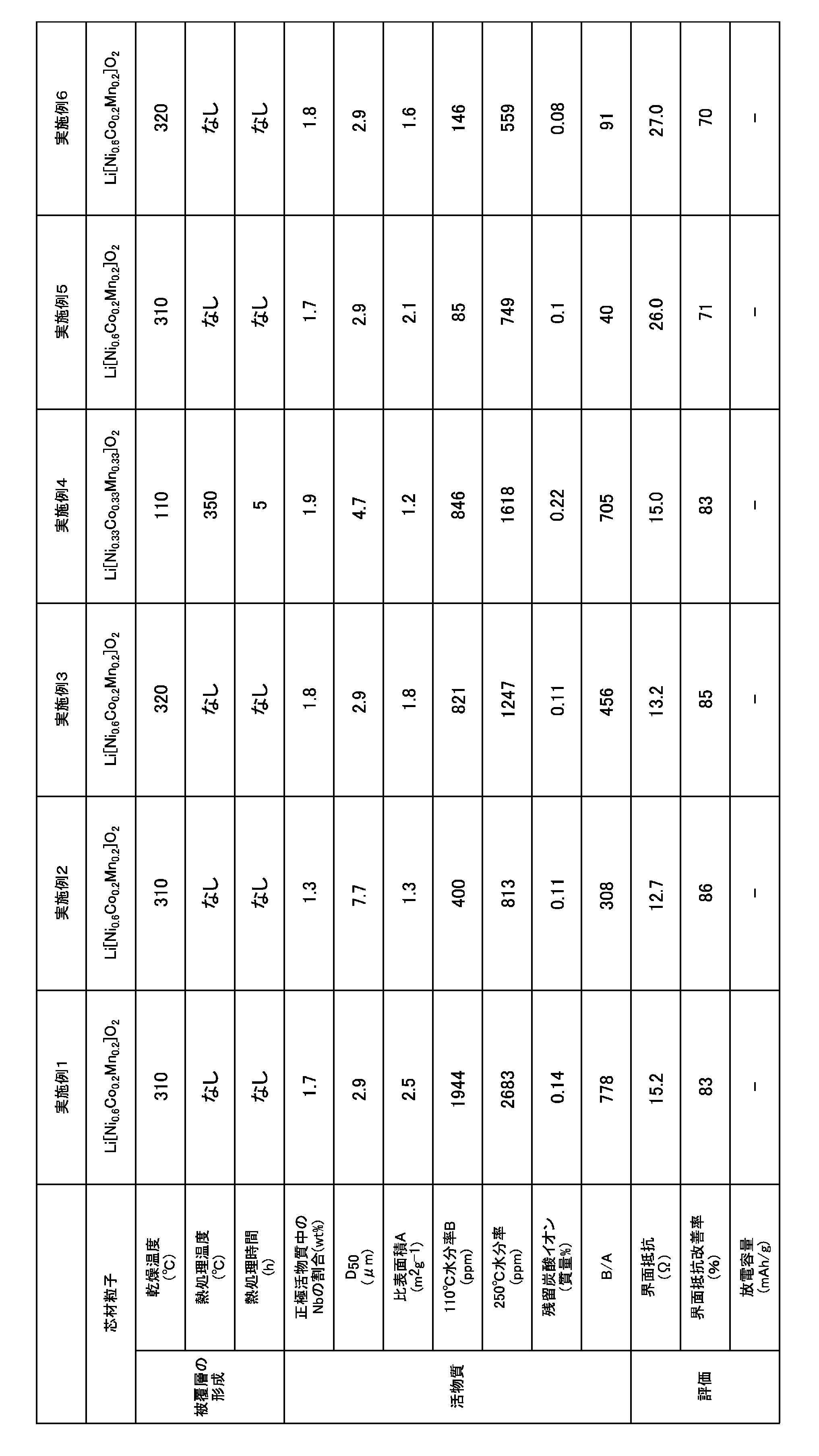
3.68gのLiOH・H2O及び24gのペルオキソニオブ酸アンモニウムを、2000mLの水に溶解して処理液を調製した。この処理液を処理液Aという。前記(1)で得られた芯材粒子200gに処理液Aを添加し、90℃以上で加熱した。90℃以上で加熱することにより、リチウム原料とペルオキソニオブ酸アンモニウムとが溶液内で反応する。これにより、芯材粒子の表面に吸着しやすい性質を持つLiNbOが、芯材粒子の表面に生成する。その後、スプレードライ造粒法によって310℃で乾燥して正極活物質を得た。得られた正極活物質のD50は2.9μmであった。このサンプルは0.145nm以上0.185nm以下の範囲に1本ピークを有し、0.28nm以上0.31nm以下の範囲にも1本ピークを有した。
(1A)において、芯材粒子の粒子径を変更した。また(2A)において、処理液Aの作製時に添加するLiOH・H2Oの量を1.7gとし、且つペルオキソニオブ酸アンモニウムの量を11.1gに変更した。これら以外は、実施例1と同様にして正極活物質を得た。このサンプルは0.145nm以上0.185nm以下の範囲に1本ピークを有し、0.28nm以上0.31nm以下の範囲にも1本ピークを有した。
表1に示す条件を採用した以外は実施例1と同様にして正極活物質を得た。このサンプルは0.145nm以上0.185nm以下の範囲に1本ピークを有し、0.28nm以上0.31nm以下の範囲にも1本ピークを有した。
(1A)において、芯材粒子の組成をNi:Co:Mn=0.33:0.33:0.33に設定した。また(2A)において、500gの芯材粒子と、6.8gのLiOH・H2Oと、44.4gのペルオキソニオブ酸アンモニウムとを2500mLの水に添加し、スラリーを作製し、乾燥温度を110℃に設定し、更に乾燥後に熱処理を350℃で5時間行った。これら以外は実施例1と同様にして正極活物質を得た。このサンプルは0.145nm以上0.185nm以下の範囲に1本ピークを有し、0.28nm以上0.31nm以下の範囲にも1本ピークを有した。
(2A)において最後に120℃で2時間真空乾燥を追加した以外は実施例1と同様にして正極活物質を得た。このサンプルは0.145nm以上0.185nm以下の範囲に1本ピークを有し、0.28nm以上0.31nm以下の範囲にも1本ピークを有した。
(2A)において最後に120℃で2時間真空乾燥を追加した以外は実施例3と同様にして正極活物質を得た。このサンプルは0.145nm以上0.185nm以下の範囲に1本ピークを有し、0.28nm以上0.31nm以下の範囲にも1本ピークを有した。
(2A)においてLiOH・H2Oを添加しなかったこと、及び熱処理を行わなかったこと以外は実施例4と同様にして正極活物質を得た。このサンプルは0.145nm以上0.185nm以下の範囲に1本ピークを有し、0.28nm以上0.31nm以下の範囲にも1本ピークを有した。
(2A)において熱処理を行わなかった以外は実施例4と同様にして正極活物質を得た。このサンプルは0.145nm以上0.185nm以下の範囲に1本ピークを有し、0.28nm以上0.31nm以下の範囲にも1本ピークを有した。
(2A)においてLiOH・H2Oの量を20.3gに変更し、また水を1000mLに変更し、熱処理を行わなかった以外は実施例4と同様にして正極活物質を得た。このサンプルは0.145nm以上0.185nm以下の範囲に1本ピークを有し、0.28nm以上0.31nm以下の範囲にも1本ピークを有した。
(1B)芯材粒子の製造
炭酸リチウムと、電解二酸化マンガンと、水酸化ニッケルと、酸化チタンをそれぞれ秤量した。これらの材料をイオン交換水中へ投入して、湿式粉砕機で粉砕して粉砕スラリーを得た。得られた粉砕スラリーを熱噴霧乾燥させて造粒粉を得た。得られた造粒粉を、静置式電気炉を用いて、大気雰囲気において、900℃で37時間焼成した。焼成物を解砕し、750℃で37時間熱処理した。その後、水洗ろ過を行い、500℃で7時間乾燥させた。解砕を行った後、解砕物を管状型静置炉に設置し、該静置炉内に供給量0.5L/minで酸素を流入させながら、725℃で5時間熱処理した。熱処理物を目開き53μmの篩で分級し、篩下のリチウムマンガン含有複合酸化物からなる芯材粒子を回収した。この芯材粒子はXRD測定で、スピネル型リチウムマンガン含有複合酸化物であることを同定した。化学分析の結果、このリチウムマンガン含有複合酸化物は、Li:4.2質量%、Ni:13.0質量%、Mn:42.5質量%、Ti:5.3質量%であった。
13.47gのLiOH・H2Oと、29.30gのペルオキソニオブ酸アンモニウムとを586mLの水に溶解して水溶液を得た。この水溶液を90℃以上で2時間加熱した後に冷却し、LiNbOを精製した。前記(1)で得られた芯材粒子2gを、Li濃度を11.4g/Lに調整した水酸化リチウム水溶液18mLに添加し、90℃以上で10分間加熱した。90℃以上で加熱することによりリチウム原料とペルオキソニオブ酸アンモニウムが溶液内で反応することにより、本発明のLiNbOが生成し、本発明のLiNbOが正極活物質の表面に吸着しやすい性質を持つためである。そこへ9.9mLの水に、精製したLiNbOを0.346g溶かして、混合溶液中へ添加して更に混合した。混合溶液をデカンテーションして120℃で乾燥後、350℃で2時間熱処理して正極活物質を得た。このサンプルは0.145nm以上0.185nm以下の範囲に1本ピークを有し、0.28nm以上0.31nm以下の範囲にも1本ピークを有した。
本比較例は、(1A)において芯材粒子の組成をNi:Co:Mn=0.33:0.33:0.33に設定し、且つ(1B)において20gの芯材粒子を、0.17gのLiOH・H2Oと、1.13gのペルオキソニオブ酸アンモニウムとが33mLの水に溶解した処理液に添加し、熱風乾燥炉にて120℃で乾燥させて水分を蒸発させた後、大気雰囲気下に500℃で5時間熱処理して正極活物質を得た例である。このサンプルは0.145nm以上0.185nm以下の範囲にピークを有さず、0.28nm以上0.31nm以下の範囲に1本ピークを有した。
本比較例は、前記(1B)で得られた芯材粒子そのものを正極活物質として用いた例である。
実施例1、4、及び7~10並びに比較例1で得られた正極活物質について、上述の方法でXAFSを測定して動径分布関数を得た。その結果を図2及び図3に示す。また、実施例及び比較例で得られた正極活物質について、上述の方法でB/Aの値、粒径D50、BET比表面積及び水分率(110℃及び250℃)を測定し、以下に述べる方法で固体電解質との界面抵抗又は放電容量を測定した。それらの結果を表1及び表2に示す。
実施例1ないし9及び比較例1の層状型正極活物質を用い、常法に従って正極層を作製した。具体的には、得られた正極活物質と、硫化物固体電解質(Argyrodite型固体電解質)であるLi5.8PS4.8Cl1.2と、導電助剤であるVGCF(登録商標)を80:17:3の質量比で混合して正極合剤を作製し、これを正極層とした。また、負極活物質としてグラファイトを用い、常法に従って負極層を作製した。次に正極層、硫化物固体電解質層(Argyrodite型固体電解質であるLi5.8PS4.8Cl1.2)、及び負極層をこの順で重ねて加圧成型し全固体電池を作製した。この全固体電池について、初期3サイクル目の充放電を行った後に放電容量の50%まで充電した後、交流インピーダンス測定を行った。測定結果の複素インピーダンス平面プロットであるCole-Coleプロットにおける、横軸との交点から界面抵抗値(Ω)を算出した。結果を図4に示す。
比較例1の界面抵抗値から実施例の界面抵抗値を引いた値を、比較例1の界面抵抗値で除して、100倍したものを界面抵抗改善率として表1及び表2に記載した。界面抵抗改善率の数値が大きいほど、界面抵抗が小さくなったことを意味する。
測定に使用した機器仕様・条件等は以下のとおりである。
・測定装置:東洋テクニカ(株)SOLARTRON 1255B FREQUENCY RESPONSEANALYZER
・交流振幅:10mV
・周波数領域:1.0×10⁶~1.0×101Hz
実施例10及び比較例2のようなスピネル型化合物では、活物質と硫化物固体電解質との界面抵抗は非常に大きく、界面抵抗が高いサンプルではほとんど放電容量が得られないことが判った。そこで、スピネル型化合物の場合は放電容量を界面抵抗の代替指標とし、評価を行った。放電容量の増加は界面抵抗の低減を示唆している。

また、表1及び表2に示す結果から明らかなとおり、各実施例で得られた正極活物質を用いた全固体電池は、界面抵抗が低減されたものであることが判る。これに対して比較例1で得られた正極活物質を用いた全固体電池は、界面抵抗が各実施例よりも高いことが判る。また、比較例2で得られた正極活物質を用いた全固体電池は、放電容量が実施例10よりも低く、界面抵抗が高いことが判る。以上のことから、本発明の活物質を用いることにより、電池性能の向上を図れることが判った。
31gのLiOH・H2O及び6.4gのペルオキソニオブ酸アンモニウムを、450mLの水に溶解して処理液を調製した。この処理液を処理液Aという。
硫酸リチウム32gを2000mLの水に溶解して処理液を調製した。この処理液を処理液Bという。
芯材粒子としてスピネル型化合物であるLi[Ni0.4Mn1.4Ti0.2]O4を用いた。
芯材粒子100gを処理液Aに添加し、90℃以上で加熱した後、固液分離により残渣Cを得た。残渣Cと900mLの処理液とBを混合し固液分離により残渣Dを得た。残渣Dを900mLの処理液Bと混合し固液分離により残渣Eを得た。残渣Eを120℃で2時間乾燥させて正極活物質を得た。90℃以上で加熱する理由は、リチウム原料とペルオキソニオブ酸アンモニウムとが溶液内で反応することによって、本発明のLiNbOが生成し、本発明のLiNbOが正極活物質の表面に吸着しやすい性質を持つためである。
得られた正極活物質は0.145nm以上0.185nm以下の範囲にピークが1つ観察され、0.28nm以上0.31nm以下の範囲にもピークが1つ観察された。
得られた正極活物質について、実施例1と同様の方法でB/Aの値、粒径D50、BET比表面積、水分率(110℃及び250℃)及び放電容量を測定した。それらの結果を表3に示す。
62gのLiOH・H2O及び6.4gのペルオキソニオブ酸アンモニウムを、450mLの水に溶解して処理液を調製した。この処理液を処理液Aという。
硫酸リチウム32gを2000mLの水に溶解して処理液を調製した。この処理液を処理液Bという。
芯材粒子としてスピネル型化合物であるLi[Ni0.4Mn1.4Ti0.2]O4を用いた。
芯材粒子100gを処理液Aに添加し、90℃以上で加熱した後、固液分離により残渣Cを得た。残渣Cと900mLの処理液Bとを混合し固液分離により残渣Dを得た。残渣Dを900mLの処理液Bと混合し固液分離により残渣Eを得る。残渣Eを200℃で2時間乾燥させて正極活物質を得た。90℃以上で加熱する理由は、実施例12と同じである。
得られた正極活物質は0.145nm以上0.185nm以下の範囲にピークが1つ観察され、0.28nm以上0.31nm以下の範囲にもピークが1つ観察された。
得られた正極活物質について、実施例1と同様の方法でB/Aの値、粒径D50、BET比表面積、水分率(110℃及び250℃)及び放電容量を測定した。それらの結果を表3に示す。
62gのLiOH・H2O及び6.2gのペルオキソニオブ酸アンモニウムを、450mLの水に溶解して処理液を調製した。この処理液を処理液Aという。
硫酸リチウム32gを2000mLの水に溶解して処理液を調製した。この処理液を処理液Bという。
芯材粒子としてスピネル型化合物であるLi[Ni0.4Mn1.4Ti0.2]O4を用いた。
芯材粒子100gを処理液Aに添加し、90℃以上で加熱した後、固液分離により残渣Cを得た。残渣Cと900mLの処理液Bとを混合し固液分離により残渣Dを得た。残渣Dを900mLの処理液Bと混合し固液分離により残渣Eを得る。残渣Eを200℃で2時間乾燥させて正極活物質を得た。90℃以上で加熱する理由は、実施例12と同じである。
得られた正極活物質は0.145nm以上0.185nm以下の範囲にピークが1つ観察され、0.28nm以上0.31nm以下の範囲にもピークが1つ観察された。
このサンプルは全固体電池によって、0.33Cの電流値で5.0Vまで充電し、更に0.01Cの電流値になるまで定電圧充電を行った後、0.33Cで3.0Vまで放電し、更に0.01Cの電流値になるまで定電圧放電を行うサイクル特性試験において63サイクル目でも113mAh/gの放電容量を示した。
得られた正極活物質について、実施例1と同様の方法でB/Aの値、粒径D50、BET比表面積、水分率(110℃及び250℃)及び放電容量を測定した。それらの結果を表3に示す。

Claims (7)
- X線吸収微細構造の測定によって得られる動径分布関数において、0.145nm以上0.185nm以下の範囲にピークが少なくとも1つ観察されるとともに、0.28nm以上0.31nm以下の範囲にピークが少なくとも1つ観察され、且つ全固体電池に用いられる活物質。
- BET比表面積A(m2/g)に対するカールフィッシャー法によって測定された110℃までの水分率B(質量ppm)の比であるB/Aの値が5以上8000以下である請求項1に記載の活物質。
- 芯材粒子と、前記芯材粒子の表面に配置された被覆層とを有し、
前記芯材粒子がリチウム金属複合酸化物を含み、
前記リチウム金属複合酸化物が、層状岩塩型化合物であるか又はスピネル型化合物である請求項1又は2に記載の活物質。 - 請求項1ないし3のいずれか一項に記載の活物質と、硫化物固体電解質とを含む正極合剤。
- 前記硫化物固体電解質が、Li元素及びS元素を含み、且つリチウムイオン伝導性を有する請求項4に記載の正極合剤。
- 前記硫化物固体電解質が、Argyrodite型構造の結晶相を有する請求項5に記載の正極合剤。
- 正極層、負極層、及び固体電解質層を備えた全固体電池において、
前記正極層が、請求項4ないし6のいずれか一項に記載の正極合剤を含む全固体電池。
Priority Applications (5)
| Application Number | Priority Date | Filing Date | Title |
|---|---|---|---|
| KR1020207031998A KR102850988B1 (ko) | 2018-09-27 | 2019-09-27 | 활물질, 그것을 사용한 정극 합제 및 전고체 전지 |
| CN201980030151.2A CN112074978A (zh) | 2018-09-27 | 2019-09-27 | 活性物质、使用了该活性物质的正极合剂和全固体电池 |
| EP19867802.1A EP3859841A4 (en) | 2018-09-27 | 2019-09-27 | ACTIVE MATERIAL, POSITIVE ELECTRODE MIXTURE AND SOLID STATE BATTERY WITH THIS ACTIVE MATERIAL |
| US17/056,339 US12603276B2 (en) | 2018-09-27 | 2019-09-27 | Active material, and positive electrode mixture and solid-state battery that use said active material |
| JP2020516782A JP7348170B2 (ja) | 2018-09-27 | 2019-09-27 | 活物質、それを用いた正極合剤及び全固体電池 |
Applications Claiming Priority (2)
| Application Number | Priority Date | Filing Date | Title |
|---|---|---|---|
| JP2018-182980 | 2018-09-27 | ||
| JP2018182980 | 2018-09-27 |
Publications (1)
| Publication Number | Publication Date |
|---|---|
| WO2020067425A1 true WO2020067425A1 (ja) | 2020-04-02 |
Family
ID=69950647
Family Applications (1)
| Application Number | Title | Priority Date | Filing Date |
|---|---|---|---|
| PCT/JP2019/038154 Ceased WO2020067425A1 (ja) | 2018-09-27 | 2019-09-27 | 活物質、それを用いた正極合剤及び全固体電池 |
Country Status (6)
| Country | Link |
|---|---|
| US (1) | US12603276B2 (ja) |
| EP (1) | EP3859841A4 (ja) |
| JP (1) | JP7348170B2 (ja) |
| KR (1) | KR102850988B1 (ja) |
| CN (1) | CN112074978A (ja) |
| WO (1) | WO2020067425A1 (ja) |
Cited By (9)
| Publication number | Priority date | Publication date | Assignee | Title |
|---|---|---|---|---|
| WO2021215215A1 (ja) * | 2020-04-20 | 2021-10-28 | パナソニックIpマネジメント株式会社 | 電池 |
| JPWO2021241417A1 (ja) * | 2020-05-27 | 2021-12-02 | ||
| JPWO2021241416A1 (ja) * | 2020-05-27 | 2021-12-02 | ||
| WO2022224611A1 (ja) * | 2021-04-20 | 2022-10-27 | パナソニックIpマネジメント株式会社 | 正極材料および電池 |
| WO2023140288A1 (ja) * | 2022-01-20 | 2023-07-27 | 住友金属鉱山株式会社 | 被覆付きリチウム二次電池用正極活物質、リチウム二次電池 |
| WO2023153346A1 (ja) * | 2022-02-08 | 2023-08-17 | 住友化学株式会社 | 固体リチウム二次電池用正極活物質及び固体リチウム二次電池用正極活物質の製造方法 |
| WO2023153344A1 (ja) * | 2022-02-08 | 2023-08-17 | 住友化学株式会社 | リチウム二次電池用正極活物質の製造方法、リチウム二次電池用正極活物質、電極および固体リチウム二次電池 |
| CN116706006A (zh) * | 2022-03-04 | 2023-09-05 | 丰田自动车株式会社 | 复合正极活性物质 |
| CN116706005A (zh) * | 2022-03-04 | 2023-09-05 | 丰田自动车株式会社 | 复合正极活性物质 |
Families Citing this family (4)
| Publication number | Priority date | Publication date | Assignee | Title |
|---|---|---|---|---|
| WO2020175506A1 (ja) * | 2019-02-27 | 2020-09-03 | 三井金属鉱業株式会社 | 活物質、それを用いた正極合剤及び固体電池 |
| WO2023070216A1 (fr) * | 2021-10-27 | 2023-05-04 | HYDRO-QUéBEC | Composés inorganiques possédant une structure de type argyrodite, leurs procédés de préparation et leurs utilisations dans des applications électrochimiques |
| WO2023230832A1 (zh) * | 2022-05-31 | 2023-12-07 | 宁德时代新能源科技股份有限公司 | 镍锰酸锂正极活性材料及其制备方法、以及使用其的二次电池 |
| JP2024000245A (ja) * | 2022-06-20 | 2024-01-05 | 株式会社東芝 | 電極材 |
Citations (7)
| Publication number | Priority date | Publication date | Assignee | Title |
|---|---|---|---|---|
| JPH11297323A (ja) * | 1998-04-08 | 1999-10-29 | Sony Corp | 非水系二次電池用正極材料及びそれを用いた非水系二次電池 |
| JP2006261072A (ja) * | 2005-03-18 | 2006-09-28 | Sony Corp | 負極活物質および電池 |
| JP2007330877A (ja) * | 2006-06-14 | 2007-12-27 | Taiheiyo Cement Corp | 水素貯蔵材料およびその製造方法 |
| JP2009032655A (ja) * | 2007-07-03 | 2009-02-12 | Sumitomo Chemical Co Ltd | リチウム複合金属酸化物 |
| JP2015153628A (ja) * | 2014-02-14 | 2015-08-24 | 古河電気工業株式会社 | 全固体二次電池 |
| US20180219229A1 (en) | 2017-02-02 | 2018-08-02 | Toyota Jidosha Kabushiki Kaisha | Composite active material particle, cathode, all-solid-state lithium ion battery, and methods for producing the same |
| WO2018164224A1 (ja) * | 2017-03-08 | 2018-09-13 | 出光興産株式会社 | 硫化物固体電解質粒子 |
Family Cites Families (18)
| Publication number | Priority date | Publication date | Assignee | Title |
|---|---|---|---|---|
| EP1742281B1 (en) * | 2004-04-27 | 2011-09-07 | Mitsubishi Chemical Corporation | Layered lithium nickel manganese cobalt composite oxide powder for material of positive electrode of lithium secondary battery, process for producing the same, positive electrode of lithium secondary battery therefrom, and lithium secondary battery |
| JP5100024B2 (ja) * | 2006-03-30 | 2012-12-19 | 住友金属鉱山株式会社 | 非水電解質二次電池用の正極活物質及びそれを用いた非水電解質二次電池 |
| JP5643025B2 (ja) * | 2010-08-19 | 2014-12-17 | 出光興産株式会社 | 硫化物系固体電解質及びその製造方法、並びにリチウムイオン電池 |
| JP5681427B2 (ja) * | 2010-09-28 | 2015-03-11 | Dowaホールディングス株式会社 | リチウム−遷移金属酸化物粉体およびその製造方法、リチウムイオン電池用正極活物質、並びにリチウムイオン二次電池 |
| JP2013097892A (ja) * | 2011-10-28 | 2013-05-20 | Nippon Electric Glass Co Ltd | リチウムイオン二次電池正極材料粉末 |
| JP6292739B2 (ja) * | 2012-01-26 | 2018-03-14 | Jx金属株式会社 | リチウムイオン電池用正極活物質、リチウムイオン電池用正極、及び、リチウムイオン電池 |
| WO2014007357A1 (ja) * | 2012-07-06 | 2014-01-09 | 住友化学株式会社 | リチウム複合金属酸化物、正極活物質、正極および非水電解質二次電池 |
| JP2014049310A (ja) * | 2012-08-31 | 2014-03-17 | Toyota Motor Corp | 活物質材料、全固体電池、および活物質材料の製造方法 |
| JP6189649B2 (ja) * | 2013-06-07 | 2017-08-30 | Dowaホールディングス株式会社 | 正極活物質粉末およびその製造法 |
| JP6034265B2 (ja) * | 2013-09-12 | 2016-11-30 | トヨタ自動車株式会社 | 活物質複合粉体及びリチウム電池並びにその製造方法 |
| JP6295966B2 (ja) * | 2014-08-08 | 2018-03-20 | トヨタ自動車株式会社 | 全固体電池 |
| JP6380221B2 (ja) * | 2015-04-27 | 2018-08-29 | トヨタ自動車株式会社 | 活物質複合粒子、電極活物質層および全固体リチウム電池 |
| JP6570934B2 (ja) * | 2015-09-16 | 2019-09-04 | 株式会社東芝 | 電池用活物質、電極、非水電解質電池、電池パック及び車 |
| WO2018012015A1 (ja) * | 2016-07-14 | 2018-01-18 | 三井金属鉱業株式会社 | 全固体型リチウム二次電池用正極活物質 |
| JP6920045B2 (ja) * | 2016-10-20 | 2021-08-18 | Dowaエレクトロニクス株式会社 | リチウム二次電池電極材料の製造方法、リチウム二次電池の製造方法 |
| JP6952467B2 (ja) * | 2017-01-24 | 2021-10-20 | 三星電子株式会社Samsung Electronics Co.,Ltd. | 全固体二次電池用正極活物質、全固体二次電池用正極活物質層、および全固体二次電池 |
| US11217785B2 (en) * | 2017-01-24 | 2022-01-04 | Samsung Electronics Co., Ltd. | Composite cathode active material and secondary battery including the same |
| KR102324996B1 (ko) * | 2017-08-14 | 2021-11-12 | 미쓰이금속광업주식회사 | 전고체형 리튬 이차전지용 양극 활물질 |
-
2019
- 2019-09-27 WO PCT/JP2019/038154 patent/WO2020067425A1/ja not_active Ceased
- 2019-09-27 US US17/056,339 patent/US12603276B2/en active Active
- 2019-09-27 EP EP19867802.1A patent/EP3859841A4/en active Pending
- 2019-09-27 KR KR1020207031998A patent/KR102850988B1/ko active Active
- 2019-09-27 CN CN201980030151.2A patent/CN112074978A/zh active Pending
- 2019-09-27 JP JP2020516782A patent/JP7348170B2/ja active Active
Patent Citations (7)
| Publication number | Priority date | Publication date | Assignee | Title |
|---|---|---|---|---|
| JPH11297323A (ja) * | 1998-04-08 | 1999-10-29 | Sony Corp | 非水系二次電池用正極材料及びそれを用いた非水系二次電池 |
| JP2006261072A (ja) * | 2005-03-18 | 2006-09-28 | Sony Corp | 負極活物質および電池 |
| JP2007330877A (ja) * | 2006-06-14 | 2007-12-27 | Taiheiyo Cement Corp | 水素貯蔵材料およびその製造方法 |
| JP2009032655A (ja) * | 2007-07-03 | 2009-02-12 | Sumitomo Chemical Co Ltd | リチウム複合金属酸化物 |
| JP2015153628A (ja) * | 2014-02-14 | 2015-08-24 | 古河電気工業株式会社 | 全固体二次電池 |
| US20180219229A1 (en) | 2017-02-02 | 2018-08-02 | Toyota Jidosha Kabushiki Kaisha | Composite active material particle, cathode, all-solid-state lithium ion battery, and methods for producing the same |
| WO2018164224A1 (ja) * | 2017-03-08 | 2018-09-13 | 出光興産株式会社 | 硫化物固体電解質粒子 |
Non-Patent Citations (2)
| Title |
|---|
| See also references of EP3859841A4 |
| TSAI, P. C. ET AL.: "Defect structure of highly Zn- doped LiNb03 single crystal revealed by extended x-ray absorption spectra", APPL. PHYS. LETT., vol. 92, 2008, pages 161902, XP012106578, DOI: 10.1063/1.2913012 * |
Cited By (17)
| Publication number | Priority date | Publication date | Assignee | Title |
|---|---|---|---|---|
| US12537223B2 (en) | 2020-04-20 | 2026-01-27 | Panasonic Intellectual Property Management Co., Ltd. | Battery |
| WO2021215215A1 (ja) * | 2020-04-20 | 2021-10-28 | パナソニックIpマネジメント株式会社 | 電池 |
| JP7742579B2 (ja) | 2020-05-27 | 2025-09-22 | パナソニックIpマネジメント株式会社 | 正極活物質、正極材料、電池、および正極活物質の製造方法 |
| JPWO2021241417A1 (ja) * | 2020-05-27 | 2021-12-02 | ||
| JPWO2021241416A1 (ja) * | 2020-05-27 | 2021-12-02 | ||
| WO2021241417A1 (ja) * | 2020-05-27 | 2021-12-02 | パナソニックIpマネジメント株式会社 | 正極活物質、正極材料、電池、および正極活物質の製造方法 |
| WO2021241416A1 (ja) * | 2020-05-27 | 2021-12-02 | パナソニックIpマネジメント株式会社 | 正極活物質、正極材料、電池、および正極活物質の製造方法 |
| JP7742578B2 (ja) | 2020-05-27 | 2025-09-22 | パナソニックIpマネジメント株式会社 | 正極活物質、正極材料、電池、および正極活物質の製造方法 |
| WO2022224611A1 (ja) * | 2021-04-20 | 2022-10-27 | パナソニックIpマネジメント株式会社 | 正極材料および電池 |
| JPWO2022224611A1 (ja) * | 2021-04-20 | 2022-10-27 | ||
| JP2023106205A (ja) * | 2022-01-20 | 2023-08-01 | 住友金属鉱山株式会社 | 被覆付きリチウム二次電池用正極活物質、リチウム二次電池 |
| WO2023140288A1 (ja) * | 2022-01-20 | 2023-07-27 | 住友金属鉱山株式会社 | 被覆付きリチウム二次電池用正極活物質、リチウム二次電池 |
| WO2023153344A1 (ja) * | 2022-02-08 | 2023-08-17 | 住友化学株式会社 | リチウム二次電池用正極活物質の製造方法、リチウム二次電池用正極活物質、電極および固体リチウム二次電池 |
| WO2023153346A1 (ja) * | 2022-02-08 | 2023-08-17 | 住友化学株式会社 | 固体リチウム二次電池用正極活物質及び固体リチウム二次電池用正極活物質の製造方法 |
| CN116706006A (zh) * | 2022-03-04 | 2023-09-05 | 丰田自动车株式会社 | 复合正极活性物质 |
| CN116706005A (zh) * | 2022-03-04 | 2023-09-05 | 丰田自动车株式会社 | 复合正极活性物质 |
| JP2023128670A (ja) * | 2022-03-04 | 2023-09-14 | トヨタ自動車株式会社 | 複合正極活物質 |
Also Published As
| Publication number | Publication date |
|---|---|
| US12603276B2 (en) | 2026-04-14 |
| US20210234158A1 (en) | 2021-07-29 |
| KR20210060371A (ko) | 2021-05-26 |
| EP3859841A1 (en) | 2021-08-04 |
| KR102850988B1 (ko) | 2025-08-27 |
| EP3859841A4 (en) | 2021-11-24 |
| JP7348170B2 (ja) | 2023-09-20 |
| JPWO2020067425A1 (ja) | 2021-08-30 |
| CN112074978A (zh) | 2020-12-11 |
Similar Documents
| Publication | Publication Date | Title |
|---|---|---|
| JP7348170B2 (ja) | 活物質、それを用いた正極合剤及び全固体電池 | |
| JP7315553B2 (ja) | 正極活物質 | |
| CN113396495B (zh) | 活性物质、使用了该活性物质的正极合剂和固体电池 | |
| Zhang et al. | Characterization of multiple metals (Cr, Mg) substituted LiNi0. 8Co0. 1Mn0. 1O2 cathode materials for lithium ion battery | |
| US9437873B2 (en) | Spinel-type lithium manganese-based composite oxide | |
| US9911518B2 (en) | Cathode active material for lithium-ion battery, cathode for lithium-ion battery and lithium-ion battery | |
| JP5790894B1 (ja) | 蓄電デバイスの電極用チタン酸リチウム粉末、及び活物質材料、並びにそれを用いた蓄電デバイス | |
| JP7348728B2 (ja) | 活物質、それを用いた正極合剤及び固体電池 | |
| Dai et al. | Improved cycling performance of LiNi0. 8Co0. 15Al0. 05O2/Al2O3 with core-shell structure synthesized by a heterogeneous nucleation-and-growth process | |
| Kim et al. | Lithium intercalation and crystal chemistry of Li3VO4 synthesized by ultrasonic nebulization as a new anode material for secondary lithium batteries | |
| US20220352500A1 (en) | Electrode Mixture and Electrode Layer and Solid-State Battery Employing Same | |
| GB2553263A (en) | Spinel-type lithium metal composite oxide | |
| GB2520642A (en) | Lithium metal complex oxide | |
| GB2528222A (en) | Positive electrode active material for lithium secondary battery | |
| KR20240129159A (ko) | 복합 활물질 | |
| JP2023180901A (ja) | チタン酸リチウム粉末、それを用いた負極活物質組成物、及び全固体二次電池 | |
| JP7506966B2 (ja) | 活物質、それを用いた正極合剤及び固体電池 | |
| KR102215318B1 (ko) | 리튬 이차전지용 양극 활물질 | |
| JP7246199B2 (ja) | 活物質、それを用いた正極合剤及び固体電池 | |
| JP7654971B2 (ja) | チタン酸リチウム粉末、それを用いた電極シート、及び蓄電デバイス | |
| WO2022168930A1 (ja) | 負極活物質組成物、及びそれを含む全固体二次電池 | |
| WO2022211106A1 (ja) | チタン含有酸化物粉末、それを用いた負極活物質組成物、及び全固体二次電池 | |
| CN115884943B (zh) | 活性物质及其制造方法、电极合剂、以及电池 | |
| Liu et al. | Phase structure and electrochemical performance control of 0.5 Li2MnO3⋅ 0.5 LiNi1/3Co1/3Mn1/3O2 based on the concentration adjustment in a molten salt synthesis system | |
| Singh et al. | Synthesis and characterization of LiMn2O4 nanoparticles using citric acid as chelating agent |
Legal Events
| Date | Code | Title | Description |
|---|---|---|---|
| ENP | Entry into the national phase |
Ref document number: 2020516782 Country of ref document: JP Kind code of ref document: A |
|
| 121 | Ep: the epo has been informed by wipo that ep was designated in this application |
Ref document number: 19867802 Country of ref document: EP Kind code of ref document: A1 |
|
| ENP | Entry into the national phase |
Ref document number: 20207031998 Country of ref document: KR Kind code of ref document: A |
|
| NENP | Non-entry into the national phase |
Ref country code: DE |
|
| ENP | Entry into the national phase |
Ref document number: 2019867802 Country of ref document: EP Effective date: 20210428 |
|
| WWG | Wipo information: grant in national office |
Ref document number: 1020207031998 Country of ref document: KR |