WO2020067445A1 - 制御装置 - Google Patents
制御装置 Download PDFInfo
- Publication number
- WO2020067445A1 WO2020067445A1 PCT/JP2019/038202 JP2019038202W WO2020067445A1 WO 2020067445 A1 WO2020067445 A1 WO 2020067445A1 JP 2019038202 W JP2019038202 W JP 2019038202W WO 2020067445 A1 WO2020067445 A1 WO 2020067445A1
- Authority
- WO
- WIPO (PCT)
- Prior art keywords
- obstacle
- real
- avoided
- control device
- value
- Prior art date
- Legal status (The legal status is an assumption and is not a legal conclusion. Google has not performed a legal analysis and makes no representation as to the accuracy of the status listed.)
- Ceased
Links
Images


Classifications
-
- G—PHYSICS
- G05—CONTROLLING; REGULATING
- G05D—SYSTEMS FOR CONTROLLING OR REGULATING NON-ELECTRIC VARIABLES
- G05D1/00—Control of position, course, altitude or attitude of land, water, air or space vehicles, e.g. using automatic pilots
- G05D1/02—Control of position or course in two dimensions
- G05D1/021—Control of position or course in two dimensions specially adapted to land vehicles
- G05D1/0212—Control of position or course in two dimensions specially adapted to land vehicles with means for defining a desired trajectory
- G05D1/0223—Control of position or course in two dimensions specially adapted to land vehicles with means for defining a desired trajectory involving speed control of the vehicle
-
- B—PERFORMING OPERATIONS; TRANSPORTING
- B25—HAND TOOLS; PORTABLE POWER-DRIVEN TOOLS; MANIPULATORS
- B25J—MANIPULATORS; CHAMBERS PROVIDED WITH MANIPULATION DEVICES
- B25J9/00—Program-controlled manipulators
- B25J9/16—Program controls
- B25J9/1674—Program controls characterised by safety, monitoring, diagnostic
- B25J9/1676—Avoiding collision or forbidden zones
-
- B—PERFORMING OPERATIONS; TRANSPORTING
- B25—HAND TOOLS; PORTABLE POWER-DRIVEN TOOLS; MANIPULATORS
- B25J—MANIPULATORS; CHAMBERS PROVIDED WITH MANIPULATION DEVICES
- B25J9/00—Program-controlled manipulators
- B25J9/16—Program controls
- B25J9/1628—Program controls characterised by the control loop
- B25J9/163—Program controls characterised by the control loop learning, adaptive, model based, rule based expert control
-
- G—PHYSICS
- G01—MEASURING; TESTING
- G01C—MEASURING DISTANCES, LEVELS OR BEARINGS; SURVEYING; NAVIGATION; GYROSCOPIC INSTRUMENTS; PHOTOGRAMMETRY OR VIDEOGRAMMETRY
- G01C21/00—Navigation; Navigational instruments not provided for in groups G01C1/00 - G01C19/00
- G01C21/26—Navigation; Navigational instruments not provided for in groups G01C1/00 - G01C19/00 specially adapted for navigation in a road network
- G01C21/34—Route searching; Route guidance
- G01C21/3453—Special cost functions, i.e. other than distance or default speed limit of road segments
-
- G—PHYSICS
- G05—CONTROLLING; REGULATING
- G05D—SYSTEMS FOR CONTROLLING OR REGULATING NON-ELECTRIC VARIABLES
- G05D1/00—Control of position, course, altitude or attitude of land, water, air or space vehicles, e.g. using automatic pilots
- G05D1/02—Control of position or course in two dimensions
- G05D1/021—Control of position or course in two dimensions specially adapted to land vehicles
- G05D1/0212—Control of position or course in two dimensions specially adapted to land vehicles with means for defining a desired trajectory
- G05D1/0217—Control of position or course in two dimensions specially adapted to land vehicles with means for defining a desired trajectory in accordance with energy consumption, time reduction or distance reduction criteria
-
- G—PHYSICS
- G05—CONTROLLING; REGULATING
- G05D—SYSTEMS FOR CONTROLLING OR REGULATING NON-ELECTRIC VARIABLES
- G05D1/00—Control of position, course, altitude or attitude of land, water, air or space vehicles, e.g. using automatic pilots
- G05D1/02—Control of position or course in two dimensions
- G05D1/021—Control of position or course in two dimensions specially adapted to land vehicles
- G05D1/0231—Control of position or course in two dimensions specially adapted to land vehicles using optical position detecting means
- G05D1/0238—Control of position or course in two dimensions specially adapted to land vehicles using optical position detecting means using obstacle or wall sensors
Definitions
- the present invention relates to a control device that controls a driving device that moves a moving body.
- the evaluation function for determining the route of the moving body includes, for each obstacle, an evaluation term for preventing the moving body from approaching the obstacle (penalty term) Hereinafter referred to as an obstacle evaluation item) (for example, see Patent Documents 1 and 2).
- an evaluation function including an obstacle evaluation term is used for each obstacle, the moving body can be moved without colliding with the obstacle.
- simply using an evaluation function that includes the obstacle evaluation term is suitable for collision with obstacles, such as when the moving body is in a stationary state and the obstacle avoidance path of the moving body becomes large. There may be cases where it cannot be avoided.
- the present invention has been made in view of such a problem, and in a case where a moving object follows a target trajectory by model predictive control, a control capable of appropriately avoiding a collision with an obstacle. It is intended to provide a device.
- a control device for controlling a driving device for moving a moving body comprising: The value of the evaluation function including the sum of the stage costs in the prediction section of a predetermined time width is minimized based on the acquisition unit for acquiring the position and a prediction model for predicting the position of the moving body from the control input to the driving device.
- a model prediction control unit that calculates the control input and supplies the driving input to the driving device to move the moving body along the target trajectory.
- the model prediction control unit that determines the presence / absence of an obstacle and, when there is no actual obstacle to be avoided, uses a standard cost as the stage cost.
- the model prediction control unit of the control device is an obstacle avoidance control unit that operates when there are a plurality of real obstacles to be avoided, and the model prediction control unit of the plurality of real obstacles acquired by the acquisition unit. Determine the position of the virtual obstacle from the position to be located between the plurality of real obstacles, as the stage cost, the standard cost, at least, the position of the virtual obstacle and the position of the moving body
- An obstacle avoidance control unit that calculates the control input that minimizes the evaluation function by using an addition result of a virtual function evaluation term obtained by multiplying a predetermined function as a parameter by a virtual obstacle weight is included. .
- control input is calculated on the assumption that a virtual obstacle exists. Therefore, according to the present control device, even if the collision between the moving object and the obstacle cannot be properly avoided by simply using the evaluation function including the obstacle evaluation term, the collision between the moving object and the obstacle can be prevented. Can be suitably avoided.
- the obstacle avoidance control means includes, as the stage cost, the standard cost, the virtual obstacle evaluation term, and, for each real obstacle to be avoided, an actual obstacle evaluation term obtained by multiplying the predetermined function by a weight. May be used as the stage cost, or the result of adding the standard cost and the virtual obstacle evaluation term may be used as the stage cost.
- the obstacle avoidance control means may say, "At the start of the operation, the calculation result of the virtual obstacle evaluation item at that time indicates that each actual obstacle to be avoided
- the value of the virtual obstacle weight is determined so that the actual obstacle evaluation term obtained by multiplying the predetermined function by the weight is equal to the sum of the values at that time. It is preferable to keep it.
- the obstacle avoidance control means sets the position of the virtual obstacle at an equal distance from the two or three real obstacles.
- the position with the shortest distance from each actual obstacle may be determined.
- the control device further includes: “The model prediction control unit further includes a determination unit that determines whether the moving body is in a deceleration state, and the obstacle avoidance control unit of the model prediction control unit includes: In a situation where there are a plurality of real obstacles to be avoided, an operation is started when the determination unit determines that the moving body has entered the deceleration state. " In addition, as the determination unit, for example, when the absolute value of the difference between the current value and the previous value of the position of the moving object or the minimum value of the evaluation function is less than a predetermined threshold, the moving object is set to the deceleration state.
- the moving object Means for determining that a deceleration state has occurred can be employed.
- the change rate of the virtual obstacle evaluation term in the direction in which the two real obstacles are arranged is used as the predetermined function. May be adopted using a function that makes the function smaller than the other directions.
- the model prediction control unit may determine that all the real obstacles whose positions have been acquired by the acquisition unit are obstacles to be avoided. Further, when the position of a plurality of real obstacles is acquired by the acquisition unit, the model prediction control unit may calculate an evaluation value representing a probability that a collision with the moving body may occur for each of the plurality of actual obstacles. It may be determined which of the plurality of real obstacles is the real obstacle to be avoided based on the calculated and calculated evaluation values for each real obstacle.
- FIG. 1 is an explanatory diagram of a schematic configuration of a control device according to an embodiment.
- FIG. 9 is an explanatory diagram of an example of a control result by the control device according to the embodiment.
- FIG. 3 is an explanatory diagram of functions of a control device according to the embodiment.
- FIG. 9 is an explanatory diagram of an example of a control result by the control device according to the embodiment.
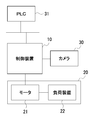
- FIG. 1 shows a usage pattern of the control device 10 according to an embodiment of the present invention
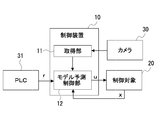
- FIG. 2 shows a schematic configuration of the control device 10 according to the present embodiment.
- the control device 10 (FIG. 1) according to the present embodiment generally includes a servo amplifier, a servo amplifier, and the like for controlling a plurality of (one in the figure) motors 21 that drive a specific load device 22 by model predictive control. This is a device called a driver or the like.
- the load device 22 is an arm or a transfer device of an industrial robot.
- a portion including a plurality of motors 21 controlled by the control device 10 and a load device 22 driven by each motor 21 is referred to as a control target 20.
- control device 10 is configured to function as the acquisition unit 11 and the model prediction control unit 12.
- the acquisition unit 11 analyzes the imaging result of the camera 30 to determine the position of each real obstacle existing around the moving object (the robot's hand or the like; hereinafter, simply referred to as the moving object) in the control target 20. This is a unit for acquiring (center position) and size. Note that the camera 30 may be configured to capture an image only within a predetermined range in the traveling direction of the moving body. The acquisition unit 11 may acquire only the position and size of each actual obstacle (in other words, the actual obstacle to be avoided) existing within a predetermined range in the traveling direction of the moving body.
- the model prediction control unit 12 allows the moving body to avoid each obstacle based on the position and size of each obstacle acquired by the acquiring unit 11 and information (position of the moving body) from the control target 20.
- the control unit 20 controls the control target 20 by model predictive control so as to move along a target trajectory specified by a PLC (Programmable Logic Controller) 31.
- PLC Programmable Logic Controller
- the control performed by the model prediction control unit 12 is as follows: “Using the prediction model of the control target 20, based on the state x of the control target, calculate the input u that minimizes the value of the following evaluation function J, To supply. "
- Expression 1 the first term on the right side of Expression 1 is a terminal cost, and L in Expression 1 is a stage cost. Further, T is a time width set in advance as the length of the prediction section in the model prediction control.
- control performed by the model prediction control unit 12 is basically the same as the generally performed model prediction control.
- model prediction control unit 12 is configured to switch the stage cost L used for calculating the J value according to the situation.
- the control device 10 is a device that can move the moving body in a three-dimensional space. However, in the following, it is assumed that the moving body moves on a plane for convenience of description.
- the model prediction control unit 12 periodically determines the presence or absence of a real obstacle to be avoided based on the position and size of each real obstacle acquired by the acquisition unit 11. More specifically, when the position and size of the real obstacle are not acquired by the acquisition unit 11 (when there is no actual obstacle), the model prediction control unit 12 determines the actual obstacle to be avoided. It is determined that it does not exist. Further, when the position and size of one or more real obstacles are acquired by the acquisition unit 11, the model prediction control unit 12 selects, from among the actual obstacles whose positions and sizes have been acquired by the acquisition unit 11, based on the position and size of each real obstacle, the value of the actual obstacle evaluating terms L k is defined by equation 2 below identifies a satisfying real obstacle that is more than a specified value. Then, the model prediction control unit 12 determines that each specified real obstacle is a real obstacle to be avoided.
- the subscript k is a number starting from 1 assigned to each real obstacle satisfying the above condition.
- x 1 and y 2 are the positions (x and y coordinates) of the moving object, and x ok and y ok are the positions (x and y coordinates) of the actual obstacle k.
- G k is a value determined according to the size of the actual obstacle k.
- the model prediction control unit 12 selects three real obstacles in descending order of the value of the real obstacle evaluation term, and selects each of the selected real obstacles.
- the real obstacle is determined to be a real obstacle to be avoided. Therefore, the maximum value of k is 3.
- the model prediction control unit 12 is also configured to periodically determine whether or not the moving body has been decelerated. This determination processing is performed even when it is determined that the moving object is in the deceleration state when the absolute value of the difference between the current value and the previous value of the position of the moving object is less than a predetermined position threshold. When the absolute value of the difference between the current value and the previous value of the minimum value of the J value becomes smaller than a predetermined J value threshold value, it may be determined that the moving body is in the deceleration state.
- the above-described determination process is performed when the absolute value of the difference between the current value and the previous value of the minimum value of the position of the moving object or the J value is less than the threshold value for a predetermined number of consecutive times.
- a process for determining that the moving body has entered the deceleration state may be performed.
- the model prediction control unit 12 periodically determines whether or not the moving object is in a deceleration state and the presence or absence of an actual obstacle to be avoided. Based on the above, a process of determining which of the following first to third conditions is satisfied is also performed.
- First condition There is no actual obstacle to be avoided.
- Second condition There is one or more real obstacles to be avoided, and the third condition is not satisfied.
- Third condition The moving object has decelerated in a situation where there are a plurality of real obstacles to be avoided.
- model predictive control unit 12 if the first condition is satisfied (when the actual obstacle to be avoided is not present), used as a stage cost L, and the reference cost L 0 following model First model predictive control, which is predictive control, is performed.
- Xxref is a target state quantity at a certain time in the prediction section
- x is a state quantity at the same time
- u is a control input at the same time.
- Q and R are a coefficient (weight coefficient) representing the weight of the state quantity in the stage cost and a coefficient (weight coefficient) representing the weight of the control input, respectively.
- model predictive control unit 12 when the second condition is satisfied, as a stage cost L, the following values, namely, the reference cost L 0 and the real obstacle evaluating terms L k for each real obstacle
- the second model prediction control which is the model prediction control using the sum of
- K kmax in the above equation is the total number of actual obstacles to be avoided ( ⁇ 3 in the present embodiment).
- the model prediction control unit 12 When the third condition is satisfied, the model prediction control unit 12 first sets the distance between each of the two or three real obstacles to be avoided, which is the same distance from each of the real obstacles, to the shortest. Determine the position. Then, the model predictive controller 12, the value of the following virtual obstacle evaluating terms calculates the weight g p as the sum of the value of the virtual obstacle evaluating terms of the actual obstacle.
- x pk and y pk are the determined positions (x and y coordinates) of the virtual obstacle.
- the model prediction control unit 12 sets the real obstacle evaluation terms L 1 , L (at the time when the moving body is at the current position) at that time.
- V 1 and V 2 of 2 gp is calculated by the following equation.
- the model predictive controller 12 as a stage cost L, starts a third model predictive control is model predictive control using the sum of the reference cost L 0 and the virtual obstacle evaluating terms L p.
- the obstacle evaluation item of each real obstacle is determined.
- a function of performing model prediction control (third model prediction control) using the evaluation function replaced with the virtual obstacle evaluation term is provided.
- the evaluation function including the obstacle evaluation term is likely to cause a problem such as the moving object becoming stationary and the obstacle avoiding route of the moving object becoming large.
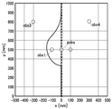
- the third model predictive control as shown by the solid line in FIG. 3, the moving body can be moved without causing the above-described problem.
- obs1 and obs2 are real obstacles to be avoided, and obs is a virtual obstacle.
- x is a target position group (command from the PCS 32) that defines the target trajectory.
- the control device 10 is configured to handle only real obstacles having a large value of the obstacle evaluation term as real obstacles to be avoided. Therefore, for example, as shown in FIG. 4, even if there are four real obstacles obs1 to obs4, the real obstacles obs3 and obs4 with small values of the obstacle evaluation terms are regarded as real obstacles to be avoided. Not handled. Therefore, as shown in FIG. 5, even when a large number of actual obstacles (obs1 to obs4 in the figure) exist, it is possible to prevent the avoidance path of the actual obstacle from becoming excessively large.
- the control device 10 can be variously modified.
- the following stage cost L may be used at the time of the third model predictive control.
- g p value the value smaller than (e.g., preset value) and to it is possible.
- the real obstacle evaluation term and the virtual obstacle evaluation term may be functions that increase in value as the distance to the moving body becomes shorter (in other words, the probability of collision with the moving body becomes higher). Therefore, a function different from the above may be used as each evaluation term.
- the virtual obstacle evaluation terms A function may be used in which the rate of change in the direction in which two real obstacles are arranged is smaller than in other directions.
- the control device 10 may be modified to a device that uses different real obstacle evaluation terms when an actual obstacle to be avoided is selected and when actual model predictive control is performed. Also, it goes without saying that the camera 30 may be a LIDAR (Light Detection and Ranging) or the like, or that the control device 10 may be modified to a device for controlling the moving direction of the vehicle.
- the camera 30 may be a LIDAR (Light Detection and Ranging) or the like, or that the control device 10 may be modified to a device for controlling the moving direction of the vehicle.
- a model prediction control unit (12) that moves the moving body along the target trajectory by supplying the moving body along the target trajectory, and determines whether there is an actual obstacle to be avoided based on information from the acquisition unit.
- the model prediction control unit (12) includes: An obstacle avoidance control unit that operates when there are a plurality of real obstacles to be avoided, and is located between the plurality of real obstacles from the positions of the plurality of real obstacles acquired by the acquisition unit. Determine the position of the virtual obstacle so as to be located, as the stage cost, the standard cost, at least a predetermined function using the position of the virtual obstacle and the position of the moving object as a parameter for the virtual obstacle; An obstacle avoidance control unit that calculates the control input that minimizes the evaluation function by using an addition result with a virtual obstacle evaluation term multiplied by a weight, A control device (10), characterized in that:
Landscapes
- Engineering & Computer Science (AREA)
- Radar, Positioning & Navigation (AREA)
- Remote Sensing (AREA)
- Physics & Mathematics (AREA)
- Automation & Control Theory (AREA)
- General Physics & Mathematics (AREA)
- Aviation & Aerospace Engineering (AREA)
- Robotics (AREA)
- Mechanical Engineering (AREA)
- Electromagnetism (AREA)
- Control Of Position, Course, Altitude, Or Attitude Of Moving Bodies (AREA)
- Feedback Control In General (AREA)
Abstract
制御装置(10)のモデル予測制御部(12)は、回避すべき複数の実障害物が存在する場合に動作する障害物回避用制御手段であって、取得部(11)によって取得された当該複数の実障害物の位置から当該複数の実障害物の間に位置するように仮想障害物の位置を決定し、ステージコストとして、標準コストと、少なくとも、前記仮想障害物の位置と前記移動体の位置とをパラメータとした所定の関数に仮想障害物用重みを乗じた仮想障害物評価項との加算結果を使用して、モデル予測制御を行う障害物回避用制御手段を含む。この構成により、モデル予測制御により移動体を目標軌道に対して追従させる場合において、障害物との衝突を好適に回避することが可能となる。
Description
本発明は、移動体を移動させる駆動装置を制御する制御装置に関する。
障害物と衝突することなく移動体を移動させるために、当該移動体の経路を決定するための評価関数に、障害物毎に、その障害物に移動体を接近させないための評価項(ペナルティ項;以下、障害物評価項と表記する)を含めることが行われている(例えば、特許文献1、2参照)。
障害物毎に障害物評価項を含めた評価関数を用いれば、障害物と衝突することなく移動体を移動させることが出来る。ただし、単に、障害物評価項を含めた評価関数を用いたのでは、移動体が停留状態になる、移動体の障害物回避経路が大回りになるといったように、障害物との衝突を好適に回避できない場合が生じ得る。
本発明は、このような問題に鑑みてなされたものであり、モデル予測制御により移動体を目標軌道に対して追従させる場合において、障害物との衝突を好適に回避することを可能とする制御装置を提供することを目的とする。
上記目的を達成するために、本発明の1観点に係る、移動体を移動させる駆動装置を制御する制御装置は、前記移動体の、目標軌道に沿った移動の障害となり得る各実障害物の位置を取得する取得部と、前記駆動装置への制御入力から前記移動体の位置を予測するための予測モデルに基づき、所定時間幅の予測区間におけるステージコストの総和を含む評価関数の値が最小となる前記制御入力を算出して前記駆動装置に供給することにより前記移動体を前記目標軌道に沿った形で移動させるモデル予測制御部であって、前記取得部からの情報により回避すべき実障害物の有無を判定し、回避すべき実障害物が存在しない場合には、前記ステージコストとして標準コストを使用する前記モデル予測制御部と、を備える。そして、制御装置のモデル予測制御部は、回避すべき複数の実障害物が存在する場合に動作する障害物回避用制御手段であって、前記取得部によって取得された当該複数の実障害物の位置から当該複数の実障害物の間に位置するように仮想障害物の位置を決定し、前記ステージコストとして、前記標準コストと、少なくとも、前記仮想障害物の位置と前記移動体の位置とをパラメータとした所定の関数に仮想障害物用重みを乗じた仮想障害物評価項との加算結果を使用して、前記評価関数を最小化する前記制御入力を算出する障害物回避用制御手段を含む。
すなわち、制御装置は、単に障害物評価項を含めた評価関数を用いたのでは、移動体と障害物との衝突を好適に回避できない場合(目標軌道を挟むように2つの障害物が存在している場合等)に、 仮想障害物が存在するとして仮定して制御入力が算出される構成を有する。従って、本制御装置によれば、単に障害物評価項を含めた評価関数を用いたのでは、移動体と障害物との衝突を好適に回避できない場合にも、移動体と障害物との衝突を好適に回避することが出来る。
障害物回避用制御手段は、前記ステージコストとして、前記標準コストと、前記仮想障害物評価項と、回避すべき各実障害物についての、前記所定の関数に重みを乗じた実障害物評価項との加算結果を使用する手段であっても、前記ステージコストとして、前記標準コストと前記仮想障害物評価項との加算結果を使用する手段であっても良い。
障害物回避用制御手段として後者の手段を採用する場合には、障害物回避用制御手段に、『動作開始時に、その時点における前記仮想障害物評価項の算出結果が、回避すべき各実障害物についての、前記所定の関数に重みを乗じた実障害物評価項の、その時点における値の総和と一致することになるように、前記仮想障害物用重みの値を決定する』機能を付与しておくことが好ましい。
また、障害物回避用制御手段は、回避すべき2つ又は3つの実障害物が存在する場合には、前記仮想障害物の位置を、当該2つ又は3つの実障害物から等距離の、各実障害物との間の距離が最も短い位置に決定しても良い。
また、制御装置に、『前記モデル予測制御部は、前記移動体が減速状態となったか否かを判定する判定手段を、さらに含み、前記モデル予測制御部の前記障害物回避用制御手段は、回避すべき複数の実障害物が存在する状況下において、前記判定手段により前記移動体が減速状態となったと判定された場合に動作を開始する』構成を採用しておいても良い。なお、判定手段としては、例えば、前記移動体の位置又は前記評価関数の最小値の今回値と前回値の差の絶対値が所定の閾値未満となったときに、前記移動体が減速状態となったと判定する手段や、前記移動体の位置又は前記評価関数の最小値の今回値と前回値の差の絶対値が所定回数連続して所定の閾値未満となったときに、前記移動体が減速状態となったと判定する手段を採用することが出来る。
また、障害物回避用制御手段として、回避すべき2つの実障害物が存在する場合には、前記所定の関数として、前記仮想障害物評価項の前記2つの実障害物の並び方向における変化率が他の方向よりも小さくなる関数を使用する手段を採用しておいても良い。
モデル予測制御部は、取得部により位置が取得された実障害物の全てが、回避すべき障害物であるとするものであっても良い。また、モデル予測制御手段は、前記取得部により複数の実障害物の位置が取得された場合、当該複数の実障害物のそれぞれについて、前記移動体との衝突が生じ得る確率を表す評価値を算出し、各実障害物について算出した評価値に基づき、前記複数の実障害物のいずれが回避すべき実障害物であるかを決定しても良い。
本発明によれば、モデル予測制御により移動体を目標軌道に対して追従させる場合において、移動体と障害物との衝突を好適に回避することが可能となる。
以下、図面を参照して本発明の実施の形態について説明する。
図1に、本発明の一実施形態に係る制御装置10の使用形態を示し、図2に、本実施形態に係る制御装置10の概略構成を示す。
本実施形態に係る制御装置10(図1)は、それぞれ、特定の負荷装置22を駆動する複数(図では、1つ)のモータ21をモデル予測制御により制御するための、一般にサーボアンプ、サーボドライバ等と称されている装置である。なお、負荷装置22とは、産業用ロボットのアームや搬送装置等のことである。以下、制御装置10により制御される複数のモータ21と各モータ21により駆動される負荷装置22とからなる部分のことを制御対象20と表記する。
図2に示してあるように、制御装置10は、取得部11及びモデル予測制御部12として機能するように構成されている。
取得部11は、カメラ30による撮像結果を解析することで、制御対象20内の移動体(ロボットの手先部等;以下、単に移動体と表記する)の周囲に存在する各実障害物の位置(中心位置)及びサイズを取得するユニットである。なお、カメラ30は、移動体の進行方向の所定範囲内のみを撮像するものであっても良い。また、取得部11は、移動体の進行方向の所定範囲内に存在する各実障害物(換言すれば、回避すべき実障害物)のみの位置及びサイズを取得するものであっても良い。
モデル予測制御部12は、取得部11により取得された各障害物の位置及びサイズと、制御対象20からの情報(移動体の位置等)とに基づき、移動体が、各障害物を回避しながら、PLC(Programmable Logic Controller)31から指示される目標軌道に沿って移動するように、モデル予測制御により制御対象20を制御するユニットである。
このモデル予測制御部12が行う制御は、『制御対象20の予測モデルを用いて、制御対象の状態xに基づき、以下の評価関数Jの値が最小となる入力uを算出して制御対象20に供給する』というものである。

なお、式1の右辺の第1項は、終端コストであり、式1におけるLは、ステージコストである。また、Tは、モデル予測制御における予測区間の長さとして予め設定されている時間幅である。
すなわち、モデル予測制御部12が行う制御は、基本的には、一般に行われているモデル予測制御と同様のものとなっている。
ただし、モデル予測制御部12は、状況に応じて、J値の算出に用いるステージコストLを切り替えるように構成されている。
以上のことを前提に、以下、モデル予測制御部12の機能を詳細に説明する。なお、制御装置10は、移動体を、3次元空間内を移動させることも可能な装置である。ただし、以下では、説明の便宜上、移動体が、平面上を移動するものであるとする。
モデル予測制御部12は、取得部11により取得された各実障害物の位置及びサイズに基づき、回避すべき実障害物の有無を周期的に判定する。より詳細には、モデル予測制御部12は、取得部11により実障害物の位置及びサイズが取得されなかった場合(実障害物が存在していない場合)には、回避すべき実障害物が存在していないと判定する。また、モデル予測制御部12は、取得部11により1つ以上の実障害物の位置及びサイズが取得された場合には、取得部11により位置及びサイズが取得された実障害物の中から、各実障害物の位置及びサイズに基づき、以下の式2で定義される実障害物評価項Lkの値が規定値以上であるという条件を満たす実障害物を特定する。そして、モデル予測制御部12は、特定した各実障害物が回避すべき実障害物であると判定する。

上記式2において、添え字kは、上記条件を満たす各実障害物に割り当てられる、1から始まる番号である。x1,y2は、移動体の位置(x、y座標)であり、xok,yokは、実障害物kの位置(x、y座標)である。また、gkは、実障害物kのサイズに応じて定められる値である。
なお、モデル予測制御部12は、上記条件を満たす実障害物が4つ以上存在していた場合には、実障害物評価項の値の降順に3つの実障害物を選択し、選択した各実障害物が、回避すべき実障害物であると判定するように構成されている。従って、kの最大値は、3である。
また、モデル予測制御部12は、移動体が減速状態となったか否かを周期的に判定するようにも構成されている。この判定処理は、移動体の位置の今回値と前回値の差の絶対値が、所定の位置閾値未満となったときに、移動体が減速状態となったと判定するものであっても、算出されたJ値の最小値の今回値と前回値の差の絶対値が、所定のJ値閾値未満となったときに、移動体が減速状態となったと判定するものであっても良い。また、誤検出を防ぐために、上記判定処理を、絶対値が移動体の位置又はJ値の最小値の今回値と前回値の差の絶対値が所定回数連続して閾値未満となったときに、移動体が減速状態となったと判定する処理としておいても良い。
上記のように、モデル予測制御部12は、移動体が減速状態となったか否かと回避すべき実障害物の有無とを周期的に判定するが、モデル予測制御部12は、双方の判定結果に基づき、以下の第1~第3条件のいずれが満たされているかを判定する処理も行う。
・第1条件:回避すべき実障害物が存在していない。
・第2条件:回避すべき1つ以上の実障害物が存在しており、且つ、第3条件が満たされていない。
・第3条件:回避すべき複数の実障害物が存在している状況下、移動体が減速状態となった。
・第1条件:回避すべき実障害物が存在していない。
・第2条件:回避すべき1つ以上の実障害物が存在しており、且つ、第3条件が満たされていない。
・第3条件:回避すべき複数の実障害物が存在している状況下、移動体が減速状態となった。
そして、モデル予測制御部12は、第1条件が満たされている場合(回避すべき実障害物が存在していない場合)には、ステージコストLとして、以下の基準コストL0を使用するモデル予測制御である第1モデル予測制御を行う。

なお、xrefは、予測区間内の或る時刻における目標状態量であり、xは、同時刻における状態量、uは、同時刻における制御入力である。また、Q及びRは、それぞれステージコストにおける状態量の重みを表す係数(重み係数)、制御入力の重みを表す係数(重み係数)である。
また、モデル予測制御部12は、第2条件が満たされている場合には、ステージコストLとして、以下の値、すなわち、基準コストL0と各実障害物の実障害物評価項Lkとの和を使用するモデル予測制御である第2モデル予測制御を行う。

なお、上記式におけるkmaxは、回避すべき実障害物の総数(本実施形態では、≦3)である。
また、モデル予測制御部12は、第3条件が満たされた場合には、まず、回避すべき2つ又は3つの実障害物から等距離の、各実障害物との間の距離が最も短い位置に決定する。次いで、モデル予測制御部12は、以下の仮想障害物評価項の値が、各実障害物の仮想障害物評価項の値の総和となる重みgpを算出する。

なお、xpk,ypkは、決定した仮想障害物の位置(x、y座標)である。
具体的には、例えば、回避すべき実障害物が2つ存在する場合、モデル予測制御部12は、その時点における(移動体が現在位置にある場合における)実障害物評価項L1、L2の値V1、V2を用いて、以下の式によりgpを算出する。

そして、モデル予測制御部12は、ステージコストLとして、基準コストL0と仮想障害物評価項Lpとの和を使用するモデル予測制御である第3モデル予測制御を開始する。
以上、説明したように、制御装置10には、回避すべき複数の実障害物が存在している状況下、移動体が減速状態となった場合に、各実障害物の障害物評価項を仮想障害物評価項に置換した評価関数を用いるモデル予測制御(第3モデル予測制御)を行う機能が付与されている。当該場合は、単に、障害物評価項を含めた評価関数を用いたのでは、移動体が停留状態になる、移動体の障害物回避経路が大回りになるといったような問題が生じ易い場合である。そして、第3モデル予測制御によれば、図3に実線で示してあるように、移動体を、上記のような不具合が生じない形で移動させることが出来る。なお、図3において、obs1、obs2は、回避すべき実障害物であり、pobsは、仮想障害物である。また、×は、目標軌道を規定する目標位置群(PCS32からの指令)である。
また、制御装置10は、障害物評価項の値の大きな実障害物のみを、回避すべき実障害物として取り扱うように構成されている。従って、例えば、図4に示したように、4つの実障害物obs1~obs4が存在していても、障害物評価項の値の小さな実障害物obs3及びobs4は、回避すべき実障害物として取り扱われない。そのため、図5にしたように、多数の実障害物(図では、obs1~obs4)が存在していても、実障害物の回避経路が過度に大回りになることを防止できることにもなる。
《変形形態》
上記した実施形態に係る制御装置10は、各種の変形が可能なものである。例えば、第3モデル予測制御時に、以下のステージコストLが使用されるようにしておいても良い。
上記した実施形態に係る制御装置10は、各種の変形が可能なものである。例えば、第3モデル予測制御時に、以下のステージコストLが使用されるようにしておいても良い。

なお、上記ステージコストLが使用されるようにする場合、gp値は、上記値よりも小さな値(例えば、予め設定されている値)とすることが出来る。
また、第3モデル予測制御時に、上記式3における各gk値を“0”とした演算が行われるようにしておいても良い。
また、実障害物評価項や仮想障害物評価項は、移動体との距離が短くなる(換言すれば、移動体との衝突確率が高くなる)につれ、値が大きくなる関数であれば良い。従って、各評価項として、上記したものとは異なる関数を使用しても良い。また、回避軌道が過度に大回りになるのを防ぐため(目標軌道から離れる期間を短くするため)に、回避すべき2つの実障害物が存在する場合には、仮想障害物評価項として、それら2つの実障害物の並び方向における変化率が他の方向よりも小さくなる関数が使用されるようにしておいても良い。
制御装置10を、回避対象とする実障害物の選択時と実際のモデル予測制御時とに、異なる実障害物評価項を使用する装置に変形することも出来る。また、カメラ30がLIDAR(Light Detection and Ranging)等であっても良いことや、制御装置10を、車輌の移動方向を制御する装置に変形しても良いことなどは、当然のことである。
《付記》
移動体を移動させる駆動装置(21)を制御する制御装置(10)であって、
前記移動体の、目標軌道に沿った移動の障害となり得る各実障害物の位置を取得する取得部(11)と、
前記駆動装置への制御入力から前記移動体の位置を予測するための予測モデルに基づき、所定時間幅の予測区間におけるステージコストの総和を含む評価関数の値が最小となる前記制御入力を算出して前記駆動装置に供給することにより前記移動体を前記目標軌道に沿った形で移動させるモデル予測制御部(12)であって、前記取得部からの情報により回避すべき実障害物の有無を判定し、回避すべき実障害物が存在しない場合には、前記ステージコストとして標準コストを使用する前記モデル予測制御部(12)と、
を備え、
前記モデル予測制御部(12)は、
回避すべき複数の実障害物が存在する場合に動作する障害物回避用制御手段であって、前記取得部によって取得された当該複数の実障害物の位置から当該複数の実障害物の間に位置するように仮想障害物の位置を決定し、前記ステージコストとして、前記標準コストと、少なくとも、前記仮想障害物の位置と前記移動体の位置とをパラメータとした所定の関数に仮想障害物用重みを乗じた仮想障害物評価項との加算結果を使用して、前記評価関数を最小化する前記制御入力を算出する障害物回避用制御手段を含む、
ことを特徴とする制御装置(10)。
移動体を移動させる駆動装置(21)を制御する制御装置(10)であって、
前記移動体の、目標軌道に沿った移動の障害となり得る各実障害物の位置を取得する取得部(11)と、
前記駆動装置への制御入力から前記移動体の位置を予測するための予測モデルに基づき、所定時間幅の予測区間におけるステージコストの総和を含む評価関数の値が最小となる前記制御入力を算出して前記駆動装置に供給することにより前記移動体を前記目標軌道に沿った形で移動させるモデル予測制御部(12)であって、前記取得部からの情報により回避すべき実障害物の有無を判定し、回避すべき実障害物が存在しない場合には、前記ステージコストとして標準コストを使用する前記モデル予測制御部(12)と、
を備え、
前記モデル予測制御部(12)は、
回避すべき複数の実障害物が存在する場合に動作する障害物回避用制御手段であって、前記取得部によって取得された当該複数の実障害物の位置から当該複数の実障害物の間に位置するように仮想障害物の位置を決定し、前記ステージコストとして、前記標準コストと、少なくとも、前記仮想障害物の位置と前記移動体の位置とをパラメータとした所定の関数に仮想障害物用重みを乗じた仮想障害物評価項との加算結果を使用して、前記評価関数を最小化する前記制御入力を算出する障害物回避用制御手段を含む、
ことを特徴とする制御装置(10)。
10・・・制御装置
11・・・取得部
12・・・モデル予測制御部
20・・・制御対象
21・・・モータ
22・・・負荷装置
30・・・カメラ
31・・・PLC
11・・・取得部
12・・・モデル予測制御部
20・・・制御対象
21・・・モータ
22・・・負荷装置
30・・・カメラ
31・・・PLC
Claims (10)
- 移動体を移動させる駆動装置を制御する制御装置であって、
前記移動体の、目標軌道に沿った移動の障害となり得る各実障害物の位置を取得する取得部と、
前記駆動装置への制御入力から前記移動体の位置を予測するための予測モデルに基づき、所定時間幅の予測区間におけるステージコストの総和を含む評価関数の値が最小となる前記制御入力を算出して前記駆動装置に供給することにより前記移動体を前記目標軌道に沿った形で移動させるモデル予測制御部であって、前記取得部からの情報により回避すべき実障害物の有無を判定し、回避すべき実障害物が存在しない場合には、前記ステージコストとして標準コストを使用する前記モデル予測制御部と、
を備え、
前記モデル予測制御部は、
回避すべき複数の実障害物が存在する場合に動作する障害物回避用制御手段であって、前記取得部によって取得された当該複数の実障害物の位置から当該複数の実障害物の間に位置するように仮想障害物の位置を決定し、前記ステージコストとして、前記標準コストと、少なくとも、前記仮想障害物の位置と前記移動体の位置とをパラメータとした所定の関数に仮想障害物用重みを乗じた仮想障害物評価項との加算結果を使用して、前記評価関数を最小化する前記制御入力を算出する障害物回避用制御手段を含む、
ことを特徴とする制御装置。 - 前記障害物回避用制御手段は、前記ステージコストとして、前記標準コストと、前記仮想障害物評価項と、回避すべき各実障害物についての、前記所定の関数に重みを乗じた実障害物評価項との加算結果を使用する、
ことを特徴とする請求項1に記載の制御装置。 - 前記障害物回避用制御手段は、前記ステージコストとして、前記標準コストと前記仮想障害物評価項との加算結果を使用する、
ことを特徴とする請求項1に記載の制御装置。 - 前記障害物回避用制御手段は、動作開始時に、その時点における前記仮想障害物評価項の算出結果が、回避すべき各実障害物についての、前記所定の関数に重みを乗じた実障害物評価項の、その時点における値の総和と一致することになるように、前記仮想障害物用重みの値を決定する、
ことを特徴とする請求項3に記載の制御装置。 - 前記障害物回避用制御手段は、回避すべき2つ又は3つの実障害物が存在する場合には、前記仮想障害物の位置を、当該2つ又は3つの実障害物から等距離の、各実障害物との間の距離が最も短い位置に決定する、
ことを特徴とする請求項1から4のいずれか一項に記載の制御装置。 - 前記モデル予測制御部は、前記移動体が減速状態となったか否かを判定する判定手段を、さらに含み、
前記モデル予測制御部の前記障害物回避用制御手段は、回避すべき複数の実障害物が存在する状況下において、前記判定手段により前記移動体が減速状態となったと判定された場合に動作を開始する、
ことを特徴とする請求項1から5のいずれか一項に記載の制御装置。 - 前記判定手段は、前記移動体の位置又は前記評価関数の最小値の今回値と前回値の差の絶対値が所定の閾値未満となったときに、前記移動体が減速状態となったと判定する、
ことを特徴とする請求項6に記載の制御装置。 - 前記判定手段は、前記移動体の位置又は前記評価関数の最小値の今回値と前回値の差の絶対値が所定回数連続して所定の閾値未満となったときに、前記移動体が減速状態となったと判定する、
ことを特徴とする請求項7に記載の制御装置。 - 前記障害物回避用制御手段は、回避すべき2つの実障害物が存在する場合には、前記所定の関数として、前記仮想障害物評価項の前記2つの実障害物の並び方向における変化率が他の方向よりも小さくなる関数を使用する、
ことを特徴とする請求項4に記載の制御装置。 - 前記モデル予測制御部は、前記取得部により複数の実障害物の位置が取得された場合、当該複数の実障害物のそれぞれについて、前記移動体との衝突が生じ得る確率を表す評価値を算出し、各実障害物について算出した評価値に基づき、前記複数の実障害物のいずれが回避すべき実障害物であるかを決定する、
ことを特徴とする請求項1に記載の制御装置。
Priority Applications (3)
| Application Number | Priority Date | Filing Date | Title |
|---|---|---|---|
| CN201980051236.9A CN112534376B (zh) | 2018-09-27 | 2019-09-27 | 控制装置 |
| EP19867804.7A EP3859457B1 (en) | 2018-09-27 | 2019-09-27 | Control device |
| US17/267,034 US11586215B2 (en) | 2018-09-27 | 2019-09-27 | Control device |
Applications Claiming Priority (2)
| Application Number | Priority Date | Filing Date | Title |
|---|---|---|---|
| JP2018182621A JP7070295B2 (ja) | 2018-09-27 | 2018-09-27 | 制御装置 |
| JP2018-182621 | 2018-09-27 |
Publications (1)
| Publication Number | Publication Date |
|---|---|
| WO2020067445A1 true WO2020067445A1 (ja) | 2020-04-02 |
Family
ID=69949835
Family Applications (1)
| Application Number | Title | Priority Date | Filing Date |
|---|---|---|---|
| PCT/JP2019/038202 Ceased WO2020067445A1 (ja) | 2018-09-27 | 2019-09-27 | 制御装置 |
Country Status (5)
| Country | Link |
|---|---|
| US (1) | US11586215B2 (ja) |
| EP (1) | EP3859457B1 (ja) |
| JP (1) | JP7070295B2 (ja) |
| CN (1) | CN112534376B (ja) |
| WO (1) | WO2020067445A1 (ja) |
Families Citing this family (3)
| Publication number | Priority date | Publication date | Assignee | Title |
|---|---|---|---|---|
| WO2022044470A1 (ja) * | 2020-08-27 | 2022-03-03 | パナソニックIpマネジメント株式会社 | 移動体制御方法、移動体制御装置、および移動体 |
| CN112346457A (zh) * | 2020-11-03 | 2021-02-09 | 智邮开源通信研究院(北京)有限公司 | 用于避障的控制方法、装置、电子设备及可读存储介质 |
| CN120702480B (zh) * | 2025-08-25 | 2025-11-04 | 天津博诺智创机器人技术有限公司 | 一种用于机器人的智能导航方法 |
Citations (3)
| Publication number | Priority date | Publication date | Assignee | Title |
|---|---|---|---|---|
| JP2006350776A (ja) * | 2005-06-17 | 2006-12-28 | Honda Motor Co Ltd | 移動体の経路生成装置 |
| JP2011186878A (ja) | 2010-03-10 | 2011-09-22 | Nissan Motor Co Ltd | 移動体走行経路生成装置 |
| JP2014130495A (ja) | 2012-12-28 | 2014-07-10 | Mitsubishi Heavy Ind Ltd | 移動制御装置、移動制御方法及びプログラム |
Family Cites Families (10)
| Publication number | Priority date | Publication date | Assignee | Title |
|---|---|---|---|---|
| JP4576445B2 (ja) * | 2007-04-12 | 2010-11-10 | パナソニック株式会社 | 自律移動型装置および自律移動型装置用プログラム |
| EP2728563A4 (en) * | 2011-06-13 | 2015-03-04 | Toyota Motor Co Ltd | DRIVING HELP DEVICE AND FAILSAFE PROCEDURE |
| JP5930892B2 (ja) * | 2011-09-07 | 2016-06-08 | 本田技研工業株式会社 | 接触状態推定装置及び軌道生成装置 |
| US10002471B2 (en) * | 2015-09-30 | 2018-06-19 | Ants Technology (Hk) Limited | Systems and methods for autonomous vehicle navigation |
| CN107168319B (zh) * | 2017-06-01 | 2020-07-28 | 同济大学 | 一种基于模型预测控制的无人车避障方法 |
| CN107807641B (zh) * | 2017-10-25 | 2019-11-19 | 上海思岚科技有限公司 | 用于移动机器人避障的方法 |
| CN107885209B (zh) * | 2017-11-13 | 2020-08-21 | 浙江工业大学 | 一种基于动态窗口与虚拟目标点的避障方法 |
| CN108398960B (zh) * | 2018-03-02 | 2021-01-26 | 南京航空航天大学 | 一种改进APF与分段Bezier相结合的多无人机协同目标追踪方法 |
| US20190354099A1 (en) * | 2018-05-18 | 2019-11-21 | Qualcomm Incorporated | Augmenting a robotic vehicle with virtual features |
| CN108549407B (zh) * | 2018-05-23 | 2020-11-13 | 哈尔滨工业大学(威海) | 一种多无人机协同编队避障的控制算法 |
-
2018
- 2018-09-27 JP JP2018182621A patent/JP7070295B2/ja active Active
-
2019
- 2019-09-27 EP EP19867804.7A patent/EP3859457B1/en active Active
- 2019-09-27 CN CN201980051236.9A patent/CN112534376B/zh active Active
- 2019-09-27 WO PCT/JP2019/038202 patent/WO2020067445A1/ja not_active Ceased
- 2019-09-27 US US17/267,034 patent/US11586215B2/en active Active
Patent Citations (3)
| Publication number | Priority date | Publication date | Assignee | Title |
|---|---|---|---|---|
| JP2006350776A (ja) * | 2005-06-17 | 2006-12-28 | Honda Motor Co Ltd | 移動体の経路生成装置 |
| JP2011186878A (ja) | 2010-03-10 | 2011-09-22 | Nissan Motor Co Ltd | 移動体走行経路生成装置 |
| JP2014130495A (ja) | 2012-12-28 | 2014-07-10 | Mitsubishi Heavy Ind Ltd | 移動制御装置、移動制御方法及びプログラム |
Non-Patent Citations (1)
| Title |
|---|
| See also references of EP3859457A4 |
Also Published As
| Publication number | Publication date |
|---|---|
| EP3859457A1 (en) | 2021-08-04 |
| US20210311487A1 (en) | 2021-10-07 |
| CN112534376A (zh) | 2021-03-19 |
| EP3859457B1 (en) | 2025-05-14 |
| EP3859457A4 (en) | 2022-05-11 |
| JP2020052816A (ja) | 2020-04-02 |
| JP7070295B2 (ja) | 2022-05-18 |
| US11586215B2 (en) | 2023-02-21 |
| CN112534376B (zh) | 2024-06-11 |
Similar Documents
| Publication | Publication Date | Title |
|---|---|---|
| CN108137051B (zh) | 用于控制自身车辆的路径规划的方法、装置以及车辆 | |
| JP7178061B2 (ja) | 人間相互作用無人搬送車 | |
| CN104755343B (zh) | 用于协调全自动驾驶的机动车运行的方法 | |
| TWI611280B (zh) | 遠端操作載具及其載具控制裝置與控制方法 | |
| JP5746347B2 (ja) | 自律移動装置 | |
| JP5768828B2 (ja) | ロボットシステム、及び、ロボットシステムの制御方法 | |
| JP4351261B2 (ja) | 先導者追従車両 | |
| JP2020516475A5 (ja) | ||
| CN110609540A (zh) | 自主移动体和用于自主移动体的控制程序 | |
| JP2019087073A (ja) | 移動式マニピュレータ、移動式マニピュレータの制御方法及びプログラム | |
| JP7070295B2 (ja) | 制御装置 | |
| US20250181075A1 (en) | Robot with Obstacle Navigation | |
| US20250073902A1 (en) | Trajectory path planning and management of robot arm movements | |
| CN112214018B (zh) | 机器人路径规划方法及装置 | |
| JP2022552335A (ja) | 自律移動装置及び倉庫物流システム | |
| JP2021194751A (ja) | 移動体制御装置、移動体制御方法、移動体制御プログラムおよび移動体制御システム | |
| CN108475060B (zh) | 位置检测装置、控制装置和移动体 | |
| CN111844038B (zh) | 一种机器人运动信息识别方法、避障方法及避障机器人、避障系统 | |
| US20250128924A1 (en) | Model-based autonomous mobile robot operations on piecewise flat floors | |
| CN115903773B (zh) | 移动体控制装置、移动体、学习装置及方法、及存储介质 | |
| CN114326707B (zh) | 机器人的移动控制方法、机器人及计算机可读存储介质 | |
| JP2005288657A (ja) | ロボット | |
| JP2023015986A (ja) | 自律走行体 | |
| JP2026078991A (ja) | 誘導制御システム | |
| US20240331167A1 (en) | Method for Determining a Trajectory for a Mobile Device |
Legal Events
| Date | Code | Title | Description |
|---|---|---|---|
| 121 | Ep: the epo has been informed by wipo that ep was designated in this application |
Ref document number: 19867804 Country of ref document: EP Kind code of ref document: A1 |
|
| NENP | Non-entry into the national phase |
Ref country code: DE |
|
| ENP | Entry into the national phase |
Ref document number: 2019867804 Country of ref document: EP Effective date: 20210428 |
|
| WWG | Wipo information: grant in national office |
Ref document number: 2019867804 Country of ref document: EP |