WO2020067512A1 - 脱気システム、液体の脱気方法、脱気モジュール、脱気システムの製造方法、及び天然資源の産生方法 - Google Patents
脱気システム、液体の脱気方法、脱気モジュール、脱気システムの製造方法、及び天然資源の産生方法 Download PDFInfo
- Publication number
- WO2020067512A1 WO2020067512A1 PCT/JP2019/038373 JP2019038373W WO2020067512A1 WO 2020067512 A1 WO2020067512 A1 WO 2020067512A1 JP 2019038373 W JP2019038373 W JP 2019038373W WO 2020067512 A1 WO2020067512 A1 WO 2020067512A1
- Authority
- WO
- WIPO (PCT)
- Prior art keywords
- degassing
- liquid
- module
- hollow fiber
- deaeration
- Prior art date
- Legal status (The legal status is an assumption and is not a legal conclusion. Google has not performed a legal analysis and makes no representation as to the accuracy of the status listed.)
- Ceased
Links
Images



Classifications
-
- B—PERFORMING OPERATIONS; TRANSPORTING
- B01—PHYSICAL OR CHEMICAL PROCESSES OR APPARATUS IN GENERAL
- B01D—SEPARATION
- B01D19/00—Degasification of liquids
- B01D19/0031—Degasification of liquids by filtration
-
- B—PERFORMING OPERATIONS; TRANSPORTING
- B01—PHYSICAL OR CHEMICAL PROCESSES OR APPARATUS IN GENERAL
- B01D—SEPARATION
- B01D63/00—Apparatus in general for separation processes using semi-permeable membranes
- B01D63/02—Hollow fibre modules
- B01D63/021—Manufacturing thereof
- B01D63/0233—Manufacturing thereof forming the bundle
-
- B—PERFORMING OPERATIONS; TRANSPORTING
- B01—PHYSICAL OR CHEMICAL PROCESSES OR APPARATUS IN GENERAL
- B01D—SEPARATION
- B01D63/00—Apparatus in general for separation processes using semi-permeable membranes
- B01D63/02—Hollow fibre modules
- B01D63/04—Hollow fibre modules comprising multiple hollow fibre assemblies
- B01D63/043—Hollow fibre modules comprising multiple hollow fibre assemblies with separate tube sheets
-
- B—PERFORMING OPERATIONS; TRANSPORTING
- B01—PHYSICAL OR CHEMICAL PROCESSES OR APPARATUS IN GENERAL
- B01D—SEPARATION
- B01D2221/00—Applications of separation devices
- B01D2221/04—Separation devices for treating liquids from earth drilling, mining
-
- B—PERFORMING OPERATIONS; TRANSPORTING
- B01—PHYSICAL OR CHEMICAL PROCESSES OR APPARATUS IN GENERAL
- B01D—SEPARATION
- B01D2313/00—Details relating to membrane modules or apparatus
- B01D2313/10—Specific supply elements
-
- B—PERFORMING OPERATIONS; TRANSPORTING
- B01—PHYSICAL OR CHEMICAL PROCESSES OR APPARATUS IN GENERAL
- B01D—SEPARATION
- B01D2313/00—Details relating to membrane modules or apparatus
- B01D2313/12—Specific discharge elements
-
- B—PERFORMING OPERATIONS; TRANSPORTING
- B01—PHYSICAL OR CHEMICAL PROCESSES OR APPARATUS IN GENERAL
- B01D—SEPARATION
- B01D2313/00—Details relating to membrane modules or apparatus
- B01D2313/12—Specific discharge elements
- B01D2313/125—Discharge manifolds
-
- B—PERFORMING OPERATIONS; TRANSPORTING
- B01—PHYSICAL OR CHEMICAL PROCESSES OR APPARATUS IN GENERAL
- B01D—SEPARATION
- B01D2315/00—Details relating to the membrane module operation
- B01D2315/22—Membrane contactor
-
- B—PERFORMING OPERATIONS; TRANSPORTING
- B01—PHYSICAL OR CHEMICAL PROCESSES OR APPARATUS IN GENERAL
- B01D—SEPARATION
- B01D2319/00—Membrane assemblies within one housing
- B01D2319/02—Elements in series
-
- B—PERFORMING OPERATIONS; TRANSPORTING
- B01—PHYSICAL OR CHEMICAL PROCESSES OR APPARATUS IN GENERAL
- B01D—SEPARATION
- B01D2325/00—Details relating to properties of membranes
- B01D2325/36—Hydrophilic membranes
Definitions
- One aspect of the present invention is a deaeration system including a deaeration unit to which a plurality of deaeration modules are connected, a method for deaeration of a liquid using the deaeration system, a deaeration module used in the deaeration system,
- the present invention relates to a method for producing a degassing system and a method for producing natural resources.
- a degassing module that degass a liquid using a hollow fiber membrane has been known. Also, a degassing system in which a plurality of degassing modules are connected to cope with an increase in size or flow rate is known.
- Patent Document 1 discloses an assembly in which a plurality of fluid contactors each having a hollow fiber membrane are connected. In this assembly, the same fluid contactors are used. Further, in this assembly, the inlet manifold for supplying the liquid is individually connected to the plurality of fluid contactors by branching corresponding to the plurality of fluid contactors. For this reason, the liquid supplied to the inlet manifold is supplied to the plurality of fluid contactors in parallel.
- each liquid supply path of a plurality of degassing modules was connected in series, and liquid was supplied in parallel to the hollow fiber membranes of the plurality of degassing modules. It has been found that the use of a degassing module lowers the degassing performance as compared with the case where the liquid is flown into one degassing module.
- one aspect of the present invention is to provide a deaeration system capable of improving the overall deaeration performance, a method for deaeration of a liquid using the deaeration system, a deaeration module used in the deaeration system, and a deaeration module. It is an object of the present invention to provide a method for producing a gas system and a method for producing a natural resource.
- each degassing module In a degassing system in which a plurality of degassing modules were connected, it was expected that the same amount of liquid would flow through each degassing module.
- each degassing module In practice, in a degassing system in which the liquid supply paths of a plurality of degassing modules are connected in series and liquid is supplied to the hollow fiber membranes of the plurality of degassing modules in parallel, each degassing module is The flow rate of the flowing liquid was different between the upstream side and the downstream side. This is considered to be due to the following reasons.
- the liquid flows from the liquid supply path to the hollow fiber side, so that the flow velocity of the liquid decreases from the upstream side to the downstream side. Then, the pressure of the liquid increases from the upstream side to the downstream side. For this reason, the flow rate of the liquid flowing to the degassing module increases toward the downstream, and the flow rate of the liquid flowing to the degassing module decreases toward the upstream. Since the degassing performance of the degassing module greatly varies depending on the flow rate of the liquid, the flow rate of the liquid between the degassing module on the upstream side and the degassing module on the downstream side deviates. It is considered that the performance was reduced.
- a degassing system includes a degassing unit to which a plurality of degassing modules for degassing a liquid are connected, and each of the plurality of degassing modules includes a liquid supply path to which a liquid is supplied.
- a deaeration unit comprising: a hollow fiber membrane bundle having a plurality of hollow fiber membranes arranged around the module; and a module container accommodating the hollow fiber membrane bundle and having an outlet formed therein for discharging a liquid.
- the liquid supply paths of a plurality of degassing modules are connected in series, and the openings through which the liquid passes are connected to the plurality of degassing modules so that the liquid is supplied in parallel to the hollow fiber membrane bundles of the plurality of degassing modules.
- the plurality of deaeration modules includes an upstream deaeration module, and a downstream deaeration module disposed downstream of the upstream deaeration module;
- the deaeration unit is connected to the liquid Is configured such that the pressure loss of the liquid from the supply port to which the liquid is supplied to the discharge port of the downstream degassing module is larger than the pressure loss of the liquid from the supply port to the discharge port of the upstream degassing module. I have.
- the liquid is supplied in parallel to the hollow fiber membrane bundles of the plurality of degassing modules by the connecting supply pipes connecting the liquid supply paths of the plurality of degassing modules in series.
- the pressure loss of the liquid from the supply port of the connection supply pipe to the discharge port of the downstream degassing module is larger than the pressure loss of the liquid from the supply port of the connection supply pipe to the discharge port of the upstream degasification module.
- this difference in pressure loss acts to offset the difference in flow velocity and pressure in the liquid flow direction.
- the divergence in the flow rate of the liquid between the upstream deaeration module and the downstream deaeration module is reduced, so that the deaeration performance of the entire deaeration system can be improved.
- the pressure loss of the liquid from the opening formed at the position corresponding to the downstream degassing module to the discharge port of the downstream degassing module is reduced by the opening formed at the position corresponding to the upstream degassing module. It may be configured to be larger than the pressure loss of the liquid from the outlet to the outlet of the upstream side degassing module.
- the pressure loss of the liquid from the opening formed at the position corresponding to the downstream deaeration module to the outlet of the module container is reduced by the pressure loss from the opening formed at the position corresponding to the upstream deaeration module to the discharge opening of the module container.
- connection supply pipe may be configured such that the pressure loss of the liquid at the position corresponding to the downstream degassing module is larger than the pressure loss of the liquid at the position corresponding to the upstream degassing module.
- the inner diameter of the connection supply pipe at the position corresponding to the downstream deaeration module may be smaller than the inner diameter of the connection supply pipe at the position corresponding to the upstream deaeration module. By doing so, the pressure loss of the liquid at the position corresponding to the downstream deaeration module of the connection supply pipe becomes larger than the pressure loss of the liquid at the position corresponding to the upstream deaeration module of the connection supply pipe. The deaeration performance of the entire deaeration system can be improved.
- the opening formed at the position corresponding to the downstream degassing module may be configured so that the pressure loss of the liquid is larger than the opening formed at the position corresponding to the upstream degassing module.
- the total area of the openings formed at the position corresponding to the downstream degassing module may be smaller than the total area of the openings formed at the position corresponding to the upstream degassing module. Further, the number of openings formed at the position corresponding to the downstream degassing module may be smaller than the number of openings formed at the position corresponding to the upstream degassing module. The size of the opening formed at the position corresponding to the downstream degassing module may be smaller than the size of the opening formed at the position corresponding to the upstream degassing module.
- the pressure loss of the liquid at the opening formed at the position corresponding to the downstream degassing module becomes larger than the pressure loss of the liquid at the opening formed at the position corresponding to the upstream degassing module.
- the deaeration performance of the entire deaeration system can be improved.
- Each of the plurality of degassing modules further includes a module inner pipe in which a hollow fiber membrane bundle is disposed around and an inner pipe opening through which a liquid passes is formed, and the inner pipe opening of the downstream degassing module is The configuration may be such that the pressure loss of the liquid is larger than the inner tube opening of the upstream side degassing module.
- the pressure loss of the liquid at the inner pipe opening of the downstream degassing module is larger than the pressure loss of the liquid at the inner pipe opening of the upstream degassing module.
- the pressure loss of the liquid from the supply port of the connection supply pipe to the discharge port of the downstream degassing module is made larger than the pressure loss of the liquid from the supply port of the connection supply pipe to the discharge port of the upstream degasification module. be able to.
- the hollow fiber membrane bundle of the downstream degassing module may be configured such that the pressure loss of the liquid is larger than that of the hollow fiber membrane bundle of the upstream degassing module.
- the density of the plurality of hollow fiber membranes in the downstream degassing module may be higher than the density of the plurality of hollow fiber membranes in the upstream degassing module.
- the thickness of the hollow fiber membrane bundle in the downstream degassing module may be larger than the thickness of the hollow fiber membrane bundle in the upstream degassing module.
- the hollow fiber membrane bundle is formed by woven a plurality of hollow fiber membranes, which are wefts, with warp yarns wound around a liquid supply path. It may be higher than the winding pressure of the fabric in the degassing module.
- the hollow fiber membrane bundle is formed by weaving a plurality of hollow fiber membranes, which are wefts, with warp yarns around the liquid supply path so that the plurality of hollow fiber membranes extend in the axial direction of the liquid supply path.
- the pitch of the warp in the downstream degassing module may be longer than the pitch of the warp in the upstream degassing module.
- the outer diameter of the hollow fiber membrane in the downstream degassing module may be larger than the outer diameter of the hollow fiber membrane in the upstream degassing module.
- the hollow fiber membrane in the downstream degassing module may have higher hydrophilicity than the hollow fiber membrane in the upstream degassing module. By doing so, the pressure loss of the liquid in the hollow fiber membrane bundle of the downstream degassing module becomes larger than the pressure loss of the liquid in the hollow fiber membrane bundle of the upstream degassing module. Degassing performance can be improved.
- the outlet of the module container of the downstream degassing module may be configured such that the pressure loss of the liquid is larger than that of the module container of the upstream degassing module.
- the outlet of the downstream degassing module is connected to the outlet of the connecting supply pipe. Can be greater than the pressure loss of the liquid from the supply port of the connecting supply pipe to the discharge port of the upstream degassing module.
- the total area of the outlet of the downstream degassing module may be smaller than the total area of the outlet of the upstream degassing module.
- the number of outlets of the downstream side degassing module may be smaller than the number of outlets of the upstream side degassing module.
- the size of the outlet of the downstream side degassing module may be smaller than the size of the outlet of the upstream side degassing module.
- a degassing system accommodates a degassing unit, and has a housing in which an inlet to which liquid is supplied from the outside and an outlet to discharge liquid to the outside are formed, and a plurality of tubes. And a suction pipe connected to the inside of the plurality of hollow fiber membranes of the plurality of degassing modules for sucking the inside of the hollow fiber membrane.
- a liquid degassing method provides the liquid degassing system according to any one of the above degassing systems, wherein the liquid is supplied from the connection supply pipe to the liquid supply passages of the plurality of degassing modules, The liquid is degassed by reducing the pressure inside each of the plurality of hollow fiber membranes.
- a degassing module is a degassing module used in any of the above degassing systems, and includes a plurality of hollow fiber membranes arranged around a liquid supply path to which liquid is supplied. And a module container that accommodates the hollow fiber membrane bundle and has a discharge port for discharging a liquid.
- a method for manufacturing a degassing system includes a hollow fiber membrane bundle having a plurality of hollow fiber membranes arranged around a liquid supply path to which a liquid is supplied, and a hollow fiber membrane bundle.
- a plurality of degassing modules each having a module container having a discharge port for discharging the liquid, and a connection supply pipe having a plurality of openings through which the liquid passes, and a connection supply pipe.
- Into the liquid supply paths of a plurality of deaeration modules connect the liquid supply paths of the plurality of deaeration modules in series by connecting supply pipes, and connect the liquid to the hollow fiber membrane bundles of the plurality of deaeration modules in parallel.
- a plurality of openings are arranged at positions corresponding to the plurality of deaeration modules so that one of the plurality of deaeration modules is an upstream side deaeration module, and the upstream of the plurality of the deaeration modules is supplied.
- Side degassing module When one disposed on the downstream side is a downstream degassing module, the pressure loss of the liquid from the supply port of the connecting supply pipe to which the liquid is supplied to the discharge port of the downstream degassing module is increased from the supply port to the upstream side. It is larger than the pressure loss of the liquid to the outlet of the side degassing module.
- a method for producing a natural resource according to one aspect of the present invention provides the method for producing a natural resource according to any one of the above-described deaeration systems, wherein the liquid is supplied from the connection supply pipe to the liquid supply paths of the plurality of deaeration modules, By depressurizing the inside of each of the plurality of hollow fiber membranes, a degassing step of degassing the liquid, and a press-fitting step of pressing the liquid degassed in the degassing step into a natural resource mining site .
- the deaeration performance of the entire deaeration system can be improved.
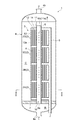
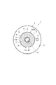
- FIG. 2 is a schematic sectional view taken along line II-II shown in FIG. 1.
- It is a schematic front view of a deaeration module.
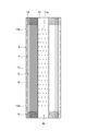
- It is a schematic sectional drawing of a deaeration module.
- It is a schematic sectional drawing of the edge part of a hollow fiber membrane bundle.
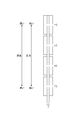
- It is the schematic diagram which abstracted the deaeration unit shown in FIG.
- It is a table
- surface which shows an example of the flow rate of the liquid which flows into each deaeration module in the deaeration system of a reference example. It is a figure for explaining the flow velocity and pressure of the liquid in each deaeration unit.
- the degassing system of the present embodiment is a system for degassing a liquid.
- the liquid to be degassed by the degassing system includes, for example, water.
- a deaeration system 1 of the present embodiment includes a deaeration unit 3 to which a plurality of deaeration modules 2 are connected, a housing 4 that houses the deaeration unit 3, and a suction pipe. 5 is provided.
- the degassing module 2 includes a module inner tube 11, a hollow fiber membrane bundle 12, and a module container 13.
- the module inner tube 11 is a tube that forms the liquid supply path 10 to which a liquid such as water is supplied on the inner peripheral side.
- the module inner tube 11 is formed in, for example, a circular tube extending linearly.
- a plurality of inner tube openings 11a are formed in the module inner tube 11.
- the inner pipe opening 11a is for passing the liquid supplied to the liquid supply path 10 of the module inner pipe 11.
- the number, position, size, and the like of the inner tube openings 11a are not particularly limited.
- the hollow fiber membrane bundle 12 has a plurality of hollow fiber membranes 14 arranged around the module inner tube 11. For this reason, the liquid supply path 10 is arranged on the inner peripheral side of the hollow fiber membrane bundle 12.
- the hollow fiber membrane bundle 12 is configured by, for example, bundling a plurality of hollow fiber membranes 14 into a cylindrical shape such as a cylindrical shape.
- the hollow fiber membrane 14 is a hollow fiber membrane that transmits gas but does not transmit liquid.
- the hollow fiber membrane bundle 12 degass the liquid that has flowed out from the inner tube opening 11a of the module inner tube 11 when the pressure inside the hollow fiber membrane 14 is reduced.
- the material, membrane shape, membrane form, etc. of the hollow fiber membrane 14 are not particularly limited.
- the material of the hollow fiber membrane 14 include polyolefin resins such as polypropylene and poly (4-methylpentene-1), silicon resins such as polydimethylsiloxane and copolymers thereof, and fluorine resins such as PTFE and vinylidene fluoride. Resin.
- the membrane shape (shape of the side wall) of the hollow fiber membrane 14 include a porous membrane, a microporous membrane, and a nonporous homogeneous membrane (non-porous membrane).
- Examples of the membrane form of the hollow fiber membrane 14 include a symmetric membrane (homogeneous membrane) in which the chemical or physical structure of the entire membrane is homogeneous, and an asymmetric membrane (heterogeneous membrane) in which the chemical or physical structure of the membrane differs depending on the membrane portion.
- An asymmetric membrane is a membrane having a nonporous dense layer and a porous layer. In this case, the dense layer may be formed anywhere in the film, such as in the surface layer of the film or inside the porous film.
- the heterogeneous film includes a composite film having different chemical structures and a multilayer structure film such as a three-layer structure.
- the hollow fiber membrane bundle 12 can be formed by, for example, a woven fabric (not shown) in which a plurality of hollow fiber membranes 14 as wefts are woven with warps.
- This woven fabric is also called a hollow fiber membrane sheet, and a plurality of hollow fiber membranes 14 are woven in a cord shape.
- This woven fabric is composed of, for example, 30 to 90 hollow fiber membranes per inch. Then, the woven fabric is wound around the module inner pipe 11 (around the liquid supply path) such that the plurality of hollow fiber membranes 14 extend in the axial direction of the module inner pipe 11 (the liquid supply path 10), thereby forming a cylindrical shape.
- the hollow fiber membrane bundle 12 can be constituted.
- the module container 13 is a container that stores the hollow fiber membrane bundle 12.
- a region between the module inner tube 11 and the module container 13 is a degassing region A where the hollow fiber membrane bundle 12 degasses the liquid.
- the module container 13 is formed, for example, in a cylindrical shape extending in the axial direction of the module inner tube 11 (liquid supply passage 10), and both ends are open.
- the module container 13 has a plurality of outlets 13a.
- the discharge port 13a is for discharging the liquid that has passed through the hollow fiber membrane bundle 12 in the degassing area A from the module container 13 (the degassing module 2).
- the number, position, size, and the like of the outlets 13a are not particularly limited.
- both ends 12 a of the hollow fiber membrane bundle 12 are fixed to the module inner tube 11 and the module container 13 by the sealing portion 15.
- the sealing portion 15 is formed of, for example, a resin.
- the resin used for the sealing portion 15 include an epoxy resin, a urethane resin, an ultraviolet curable resin, and a polyolefin resin such as polyethylene and polypropylene.
- the sealing portion 15 is filled in the entire region between the module inner tube 11 and the module container 13 except for the inside of the hollow fiber membrane 14. That is, the sealing portion 15 is filled between the hollow fiber membranes 14, between the hollow fiber membrane bundle 12 and the module inner tube 11, and between the hollow fiber membrane 14 and the module container 13. Is not filled inside.
- the inside of the hollow fiber membrane 14 is opened from the sealing portion 15 to both ends of the degassing module 2, and the inside of the hollow fiber membrane 14 can be sucked from both ends of the degassing module 2. It has become.
- the openings at both ends of the module container 13 are intake openings that open or expose the inside of the hollow fiber membrane 14 so that the inside of the hollow fiber membrane 14 can be suctioned to reduce the pressure.
- the deaeration unit 3 has a connection supply pipe 6 that connects the liquid supply paths 10 of the plurality of deaeration modules 2 in series.
- the connection supply pipe 6 is one long pipe connected to the plurality of degassing modules 2, and forms a liquid supply path 10 of the plurality of degassing modules 2 on the inner peripheral side. For this reason, the plurality of degassing modules 2 are connected in series by the connection supply pipe 6 in appearance.
- the number of degassing modules 2 constituting the degassing unit 3 is not particularly limited, the following description will be made assuming that four degassing modules 2 are connected as an example.
- the four deaeration modules 2 are called a deaeration module 2A, a deaeration module 2B, a deaeration module 2C, and a deaeration module 2D in the order of the flow direction of the liquid in the connection supply pipe 6.
- the deaeration module 2A is the deaeration module 2 arranged on the most upstream side
- the deaeration module 2D is the deaeration module 2 arranged on the most downstream side.
- the deaeration unit 3 is, for example, erected in the vertical direction so that the liquid flows upward from below in the connection supply pipe 6.
- the deaeration module 2A disposed on the most upstream side is disposed on the lowermost side
- the deaeration module 2D disposed on the most downstream side is disposed on the uppermost side.
- connection supply pipe 6 At the upstream end of the connection supply pipe 6, a supply port 6a through which liquid is supplied to the connection supply pipe 6 is formed. The downstream end of the connection supply pipe 6 is sealed. The inner peripheral side of the connection supply pipe 6 forming the liquid supply passage 10 of the plurality of degassing modules 2 is penetrated from the upstream side to the downstream side. For this reason, although the member which becomes a resistance of the flow of the liquid may be arranged on the inner peripheral side of the connection supply pipe 6 (the module inner pipe 11 of each degassing module 2), the connection supply pipe 6 is sealed. There is no member for blocking the flow of liquid. Then, the liquid supplied from the supply port 6 a is supplied in series to the liquid supply paths 10 of the plurality of degassing modules 2 by the connection supply pipe 6.
- connection supply pipe 6 openings 6b through which the liquid passes are formed at positions corresponding to the plurality of degassing modules 2 so that the liquid is supplied in parallel to the hollow fiber membrane bundles 12 of the plurality of degassing modules 2. ing. Therefore, the liquid supplied to the supply port 6a of the connection supply pipe 6 is supplied to the deaeration area A of each deaeration module 2 from the opening 6b formed at a position corresponding to each deaeration module 2 ( Flows out). As a result, the liquid is supplied to the hollow fiber membrane bundles 12 of the plurality of degassing modules 2 in parallel.
- Each degassing module 2 and the connection supply pipe 6 may be close to each other or may be separated from each other.
- the inner pipe opening 11a of each degassing module 2 and the opening 6b of the connection supply pipe 6 are formed at a position at least partially overlapping.
- the liquid can be supplied from the connection supply pipe 6 to the degassing area A of each degassing module 2.
- the housing 4 is formed with an inlet 4 a through which liquid is supplied from outside the housing 4 and an outlet 4 b through which liquid is discharged from the housing 4.
- the entrance 4 a is formed, for example, at the lower end of the housing 4.
- the inlet 4a communicates with the supply port 6a of the connection supply pipe 6. Therefore, the liquid supplied from the inlet 4a is supplied to the connection supply pipe 6 from the supply port 6a.
- the outlet 4b is formed, for example, at the upper end of the housing 4.
- the outlet 4b communicates with each outlet 13a of the module container 13. Therefore, the liquid discharged from each discharge port 13a is discharged from the outlet 4b of the housing 4.
- the housing 4 is provided with a housing sealing portion 7 and a deaeration unit support portion 8.
- the casing sealing portion 7 fixes the upstream end of the connection supply pipe 6 to the inner peripheral surface of the casing 4. Further, the casing sealing section 7 divides the internal area of the casing 4 into an upstream area B on the inlet 4a side and a downstream area C on the outlet 4b side via the degassing unit 3.
- a metal-lined resin such as stainless steel, a fiber-reinforced resin (FRP), or iron is used.
- the housing sealing portion 7 is filled in the entire region between the connection supply pipe 6 and the housing 4 except for the inside of the connection supply pipe 6. That is, the casing sealing portion 7 is filled between the connection supply pipe 6 and the casing 4, but is not filled inside the connection supply pipe 6. For this reason, the inside of the connection supply pipe 6 is opened from the supply port 6a to the upstream area B, and the liquid supplied to the upstream area B from the inlet 4a is supplied only from the supply port 6a to the inside of the connection supply pipe 6. And supplied to the deaeration area A of each deaeration module 2 from the opening 6b and the inner tube opening 11a.
- the deaeration unit supporting portion 8 is fixed to the upper end of the deaeration unit 3 and the housing 4 and supports the upper end of the deaeration unit 3.
- the deaeration unit supporting portion 8 is formed, for example, in a rod shape extending from the deaeration unit 3 to the housing 4, and does not seal the space between the deaeration unit 3 and the housing 4. Therefore, the liquid discharged from the discharge port 13a to the downstream area C is discharged from the outlet 4b to the outside of the housing 4 without being blocked by the deaeration unit support portion 8.
- the suction pipe 5 is communicated with the inside of the plurality of hollow fiber membranes 14 of the plurality of degassing modules 2 to suck (evacuate) the inside of the plurality of hollow fiber membranes 14.
- the suction tube 5 extends through the housing 4 to the outside of the housing 4 for suction by a suction pump such as a vacuum pump provided outside the housing 4.
- a suction pump such as a vacuum pump provided outside the housing 4.
- the inside of the hollow fiber membrane 14 is open from the sealing portion 15 to both ends of the degassing module 2. Therefore, the suction pipes 5 are connected to both ends of the degassing module 2 in which the inside of the hollow fiber membrane 14 is open.
- the inside of the hollow fiber membrane 14 can be sucked from both ends of the degassing module 2 by sucking the suction pipe 5.
- connection supply pipe 6 since the plurality of degassing modules 2 are externally connected in series by the connection supply pipe 6, between the degassing modules 2 adjacent to each other along the connection supply pipe 6, the other side is connected. Are arranged facing each other. Therefore, one suction pipe 5 may be connected to the facing end face.
- a liquid such as water is supplied from the inlet 4a of the housing 4 to the upstream region B of the housing 4. Then, the liquid supplied to the upstream area B is supplied from the supply port 6 a to the connection supply pipe 6, passes through the opening 6 b of the connection supply pipe 6 and the inner pipe opening 11 a of each degassing module 2, and passes through each deaeration. It is supplied to the degassing area A of the module 2. Thereby, the liquid is supplied in parallel to the hollow fiber membrane bundle 12 of each degassing module 2. In the degassing area A, the liquid supplied from the inner tube opening 11a is discharged from the outlet 13a after passing between the plurality of hollow fiber membranes 14 in the hollow fiber membrane bundle 12.
- the flow rate of the liquid flowing through each degassing module was analyzed.
- the degassing modules were completely the same, and were a first degassing module, a second degassing module, a third degassing module, and a fourth degassing module in the order of the liquid flow direction.
- the analysis software includes ANSYS Fleunt Ver. 18.2 was used.
- the liquid had a density of 1025.5 kg / m 3 and a viscosity of 0.001164 Pa ⁇ s, using seawater as a model.
- the hollow fiber membrane bundle has a pressure coefficient of 1.9 ⁇ 10 10 based on the analysis value of one degassing module, using a porous (flow-resistant channel) model as a model.
- EF-040P manufactured by DIC Corporation was used.
- the total flow rate of the liquid supplied to the degassing system of the reference example was two types, 4 m 3 / h and 24 m 3 / h.
- FIG. 7 shows the analysis result.
- the flow rate of the liquid flowing to the degassing module increased toward the downstream side, and the flow rate of the liquid flowing to the degassing module decreased toward the upstream side.
- the divergence rate of the flow rate of the liquid flowing through each degassing module increased.
- the divergence rate is the maximum divergence rate on the positive side and the negative side with respect to the ideal flow rate of the liquid flowing through each degassing module.
- the ideal flow rate of the liquid flowing through each degassing module is a value obtained by dividing the total flow rate by the number of degassing modules (4 in the reference example).
- FIG. 8 shows a model of the analysis result.
- the deaeration unit shown in FIG. 8 corresponds to the deaeration unit 3 shown in FIG.
- the liquid supplied to the connection supply pipe sequentially flows from the upstream side to the deaeration area of the degassing module, and thus the flow velocity of the liquid flowing through the connection supply pipe from the upstream side to the downstream side Becomes lower.
- the pressure of the liquid flowing through the connection supply pipe increases from the upstream side to the downstream side. In other words, the pressure of the liquid flowing through the connection supply pipe decreases from the downstream side toward the upstream side.
- the degassing performance of the entire degassing system is a single degassing module. Significantly lower than the degassing performance.
- any one of the deaeration modules 2 is defined as an upstream deaeration module 2 (upstream deaeration module), and a deaeration downstream of the upstream module.
- the module 2 is referred to as a downstream degassing module 2 (downstream degassing module).
- the deaeration module 2A is the upstream deaeration module 2
- one of the deaeration module 2B, the deaeration module 2C, and the deaeration module 2D is the downstream deaeration module 2.
- the pressure loss of the liquid from the supply port 6a of the connection supply pipe 6 to the discharge port 13a of the downstream degassing module 2 is determined by the pressure loss of the liquid from the supply port 6a to the discharge port of the upstream degassing module 2. It is configured to be larger than the pressure loss of the liquid up to 13a.
- the pressure loss refers to the pressure loss of the liquid flowing through the degassing system 1.
- the pressure loss of the liquid from the opening 6b formed at a position corresponding to the downstream degassing module 2 to the discharge port 13a of the downstream degassing module 2 is reduced by the degassing unit 3 on the upstream side.
- the pressure loss of the liquid from the opening 6b formed at the position corresponding to the gas module 2 to the discharge port 13a of the degassing module 2 on the downstream side may be configured to be larger.
- any two deaeration modules may satisfy the above relationship.
- the pressure loss may be the same (substantially the same) between the adjacent degassing modules 2 along the connection supply pipe 6.
- the fact that the above-described pressure loss is the same between the degassing modules 2 adjacent to each other along the connection supply pipe 6 means that a case where the pressure loss differs by about 30% due to a manufacturing error or the like is included.
- the pressure loss of the liquid from the supply port 6a to the discharge port 13a of each deaeration module 2 is determined by, for example, measuring the pressure of the liquid at the supply port 6a and the pressure of the liquid at the discharge port 13a of each deaeration module 2 using a pressure gauge or the like. It can be obtained by measuring and calculating the difference.
- the hollow fiber membrane bundles 12 of the plurality of degassing modules 2 are connected to the liquid supply passages 10 of the plurality of degassing modules 2 in series. Liquids are supplied in parallel.
- the pressure loss of the liquid from the supply port 6a of the connection supply pipe 6 to the discharge port 13a of the downstream degassing module 2 increases the discharge pressure 13a of the upstream deaeration module 2 from the supply port 6a of the connection supply pipe 6. Up to greater than the pressure drop of the liquid. For this reason, this difference in pressure loss acts to offset the difference in flow velocity and pressure in the liquid flow direction.
- the divergence in the flow rate of the liquid between the upstream deaeration module 2 and the downstream deaeration module 2 is reduced, so that the deaeration performance of the entire deaeration system 1 can be improved.
- the pressure loss of the liquid from the opening 6b formed at the position corresponding to the downstream degassing module 2 to the discharge port 13a of the downstream degassing module 2 is reduced by the position corresponding to the upstream degassing module 2.
- the downstream deaeration module 2 is more downstream than the upstream deaeration module 2. , Makes it difficult for the liquid to flow. Thereby, the deaeration performance of the entire deaeration system 1 can be improved.
- the pressure loss from the supply port 6a to the discharge port 13a of each degassing module 2 includes, for example, [1] the pressure loss of the liquid in the connection supply pipe 6, and [2] the liquid loss in the opening 6b of the connection supply pipe 6. [3] The pressure loss of the liquid at the inner tube opening 11a of the module inner tube 11, [4] the pressure loss of the liquid at the hollow fiber membrane bundle 12, and the [5] The pressure loss of the liquid at the outlet 13a of the module container 13. And the pressure loss of the liquid. For this reason, for example, by adjusting some or all of them, the pressure loss from the supply port 6a to the discharge port 13a of the downstream degassing module 2 can be reduced. The pressure loss can be greater than the pressure loss up to the outlet 13a.
- the pressure loss of the liquid at the position corresponding to the degassing module 2 on the downstream side of the connection supply pipe 6 is made larger than the pressure loss of the liquid at the position corresponding to the degasification module 2 on the upstream side of the connection supply pipe 6.
- the pressure loss of the liquid from the supply port 6a of the connection supply pipe 6 to the discharge port 13a of the downstream degassing module 2 is reduced from the supply port 6a of the connection supply pipe 6 to the discharge port 13a of the upstream degasification module 2. Pressure loss of the liquid.
- the inner diameter of the connection supply pipe 6 at the position corresponding to the downstream degassing module 2 may be smaller than the inner diameter of the connection supply pipe 6 at the position corresponding to the upstream degassing module 2.
- the connection supply pipe 6 a pipe whose inner diameter decreases in a tapered shape from the upstream side to the downstream side may be used, and a pipe whose inner diameter gradually decreases from the upstream side to the downstream side may be used. May be used.
- the pressure loss of the liquid at the position corresponding to the degassing module 2 on the downstream side of the connection supply pipe 6 is reduced by the pressure of the liquid at the position corresponding to the degasification module 2 on the upstream side of the connection supply pipe 6. It can be larger than the loss.
- the opening 6b formed at the position corresponding to the downstream degassing module 2 is formed at the position corresponding to the upstream degassing module 2.
- the configuration is such that the pressure loss of the liquid is greater than that of the formed opening 6b.
- the pressure loss of the liquid at the opening 6b formed at the position corresponding to the downstream degassing module 2 is reduced by the pressure loss of the liquid at the opening 6b formed at the position corresponding to the upstream degassing module 2.
- the pressure loss of the liquid from the supply port 6a of the connection supply pipe 6 to the discharge port 13a of the downstream degassing module 2 can be reduced by increasing the pressure loss of the liquid from the supply port 6a of the connection supply pipe 6 to the upstream deaeration module.
- the pressure loss of the liquid up to the second outlet 13a can be made larger.
- the total area of the openings 6b formed at the position corresponding to the downstream degassing module 2 is larger than the total area of the openings 6b formed at the position corresponding to the upstream degassing module 2. May also be small. Further, for example, the number of openings 6b formed at a position corresponding to the downstream degassing module 2 may be smaller than the number of openings 6b formed at a position corresponding to the upstream degassing module 2. . Also, for example, the size of the opening 6b formed at the position corresponding to the downstream degassing module 2 is smaller than the size of the opening 6b formed at the position corresponding to the upstream degassing module 2. Good.
- the pressure loss of the liquid at the opening 6b formed at the position corresponding to the downstream degassing module 2 is reduced by the liquid at the opening 6b formed at the position corresponding to the upstream degassing module 2.
- the inner pipe opening 11a of the downstream degassing module 2 is more liquid than the inner pipe opening 11a of the upstream degassing module 2.
- the pressure loss is configured to be large.
- the connection supply pipe is formed. 6, the pressure loss of the liquid from the supply port 6a to the discharge port 13a of the downstream degassing module 2 is reduced by the pressure of the liquid from the supply port 6a of the connecting supply pipe 6 to the discharge port 13a of the upstream degassing module 2. It can be larger than the loss.
- the total area of the inner pipe opening 11a of the downstream degassing module 2 may be smaller than the total area of the inner pipe opening 11a of the upstream degassing module 2.
- the number of the inner pipe openings 11a of the downstream degassing module 2 may be smaller than the number of the inner pipe openings 11a of the upstream degassing module 2.
- the size of the inner pipe opening 11a of the downstream degassing module 2 may be smaller than the size of the inner pipe opening 11a of the upstream degassing module 2. In this way, the pressure loss of the liquid at the inner pipe opening 11a of the downstream degassing module 2 can be made larger than the pressure loss of the liquid at the inner pipe opening 11a of the upstream degassing module 2. .
- the pressure loss of the hollow fiber membrane bundle 12 of the downstream degassing module 2 is higher than that of the hollow fiber membrane bundle 12 of the upstream degassing module 2. It is constituted so that it may become.
- connection supply pipe 6 By making the pressure loss of the liquid in the hollow fiber membrane bundle 12 of the degassing module 2 on the downstream side larger than the pressure loss of the liquid in the hollow fiber membrane bundle 12 of the degassing module 2 on the upstream side, the connection supply pipe 6 The pressure loss of the liquid from the supply port 6a to the discharge port 13a of the downstream degassing module 2 is calculated from the pressure loss of the liquid from the supply port 6a of the connecting supply pipe 6 to the discharge port 13a of the upstream degassing module 2. Can also be increased.
- the density of the plurality of hollow fiber membranes 14 in the downstream degassing module 2 may be higher than the density of the plurality of hollow fiber membranes 14 in the upstream degassing module 2.
- the gap between the plurality of hollow fiber membranes 14 is narrowed, and the liquid passage resistance to the hollow fiber membrane bundle 12 is increased. Therefore, the pressure loss of the liquid in the hollow fiber membrane bundle 12 of the degassing module 2 on the downstream side becomes larger than the pressure loss of the liquid in the hollow fiber membrane bundle 12 of the degassing module 2 on the upstream side.
- the thickness of the hollow fiber membrane bundle 12 in the downstream degassing module 2 may be larger than the thickness of the hollow fiber membrane bundle 12 in the upstream degassing module 2.
- the passage resistance of the liquid to the hollow fiber membrane bundle 12 increases. Therefore, the pressure loss of the liquid in the hollow fiber membrane bundle 12 of the degassing module 2 on the downstream side becomes larger than the pressure loss of the liquid in the hollow fiber membrane bundle 12 of the degassing module 2 on the upstream side.
- the module inner tube 11 (around the liquid supply path 10), for example, on the downstream side May be higher than the winding pressure of the fabric in the upstream degassing module 2.
- the woven fabric may be wound around the module inner pipe 11 (around the liquid supply path 10) such that the plurality of hollow fiber membranes 14 extend in the axial direction of the module inner pipe 11 (the liquid supply path 10). .
- the gap between the plurality of hollow fiber membranes 14 is narrowed, and the passage resistance of the liquid to the hollow fiber membrane bundle 12 is increased. Therefore, the pressure loss of the liquid in the hollow fiber membrane bundle 12 of the degassing module 2 on the downstream side becomes larger than the pressure loss of the liquid in the hollow fiber membrane bundle 12 of the degassing module 2 on the upstream side.
- a fabric in which the hollow fiber membrane bundle 12 is formed by weaving a plurality of hollow fiber membranes 14 as wefts with warp yarns is formed by a plurality of hollow fiber membranes 14 in the axial direction of the module inner tube 11 (liquid supply passage 10).
- the pitch of the warp in the downstream degassing module 2 is larger than the pitch of the warp in the upstream degassing module 2. May be longer.
- the woven fabric is wound around the inner tube 11 of the module, the hollow fiber membrane 14 on the outer peripheral side tries to enter between adjacent hollow fiber membranes 14 on the inner peripheral side.
- the pitch of the warp yarns in the degassing module 2 is short, the interval between the hollow fiber membranes 14 on the outer peripheral side is narrowed by the warp yarns on the inner peripheral side. It is difficult to get inside. As a result, the density of the hollow fiber membrane 14 decreases.
- the pitch of the warp yarns in the degassing module 2 is long, the interval between the hollow fiber membranes 14 on the outer peripheral side becomes longer due to the support by the warp yarns on the inner peripheral side. It is easier to get into it. As a result, the density of the hollow fiber membrane 14 increases. Therefore, the pressure loss of the liquid in the hollow fiber membrane bundle 12 of the degassing module 2 on the downstream side becomes larger than the pressure loss of the liquid in the hollow fiber membrane bundle 12 of the degassing module 2 on the upstream side.
- the outer diameter of the hollow fiber membrane 14 in the downstream degassing module 2 may be larger than the outer diameter of the hollow fiber membrane 14 in the upstream degassing module 2.
- the gap between the hollow fiber membranes 14 is narrowed by increasing the outer diameter of the hollow fiber membranes 14, and the liquid passage resistance to the hollow fiber membrane bundle 12 is reduced. growing. Therefore, the pressure loss of the liquid in the hollow fiber membrane bundle 12 of the degassing module 2 on the downstream side becomes larger than the pressure loss of the liquid in the hollow fiber membrane bundle 12 of the degassing module 2 on the upstream side.
- the hollow fiber membrane 14 in the downstream degassing module 2 may have higher hydrophilicity than the hollow fiber membrane 14 in the upstream degassing module 2. As the hydrophilicity of the hollow fiber membrane 14 increases, the contact resistance of the liquid to the hollow fiber membrane 14 increases. Therefore, the pressure loss of the liquid in the hollow fiber membrane bundle 12 of the degassing module 2 on the downstream side becomes larger than the pressure loss of the liquid in the hollow fiber membrane bundle 12 of the degassing module 2 on the upstream side.
- the pressure loss of the liquid at the outlet 13 a of the module container 13 is larger at the outlet 13 a of the downstream degassing module 2 than at the outlet 13 a of the upstream degassing module 2. It is constituted so that it may become.
- the total area of the outlet 13a of the downstream degassing module 2 may be smaller than the total area of the outlet 13a of the upstream degassing module 2.
- the number of outlets 13a of the downstream degassing module 2 may be smaller than the number of outlets 13a of the upstream degassing module 2.
- the size of the outlet 13a of the downstream degassing module 2 may be smaller than the size of the outlet 13a of the upstream degassing module 2. In this way, the pressure loss of the liquid at the outlet 13a of the degassing module 2 on the downstream side can be made larger than the pressure loss of the liquid at the outlet 13a of the degassing module 2 on the upstream side.
- connection supply pipe 6 is inserted into the liquid supply paths 10 of the plurality of degassing modules 2. Then, the liquid supply paths 10 of the plurality of deaeration modules 2 are connected in series by the connection supply pipe 6. Further, the plurality of openings 6b of the connection supply pipe 6 are arranged at positions corresponding to the plurality of degassing modules 2 so that the liquid is supplied to the hollow fiber membrane bundles 12 of the plurality of degassing modules 2 in parallel.
- any one of the deaeration modules 2 is referred to as an upstream deaeration module 2 (upstream deaeration module), and any one of the deaeration modules downstream of the upstream module.
- the air module 2 is referred to as a downstream deaeration module 2 (downstream deaeration module).
- the pressure loss of the liquid from the supply port 6a of the connection supply pipe 6 to the discharge port 13a of the downstream degassing module 2 is reduced by the pressure of the liquid from the supply port 6a to the discharge port 13a of the upstream degassing module 2. Make it bigger than the loss.
- Such setting of the liquid pressure loss can be performed by the various methods described above.
- each degassing module is described as including the module inner tube.
- a module inner tube may not be provided.
- the hollow fiber membrane bundle (fabric) of each degassing module is directly wound around the connection supply pipe.
- the method for using and using the degassing system of the present invention is not particularly limited.
- a method for producing natural resources such as a jet boring method, an in-situ leaching method (ISL), and a water flooding method may be used.
- ISL in-situ leaching method
- water flooding method a water flooding method
- the liquid is supplied from the connection supply pipe to the liquid supply paths of the plurality of degassing modules, and By depressurizing the inside of the plurality of hollow fiber membranes, a degassing step of degassing the liquid, and a press-fitting step of pressing the liquid degassed in the degassing step into a natural resource mining site, Prepare.
- the natural resources include metal minerals such as copper and uranium, and fuel minerals such as crude oil, natural gas, shale oil, and shale gas.
- the liquid include water.
- the natural resources are fuel minerals
- examples of the liquid include seawater, accompanying water, and fracturing fluid.
- Associated water is water produced when producing natural resources.
- the deaeration unit used in the present invention can be manufactured by connecting a plurality of deaeration modules in advance, and then transported to the place of use. It can also be manufactured in conjunction with the location where the system is used. In the unlikely event that any of the degassing modules becomes defective, only the relevant degassing module needs to be replaced, and the handling during transfer during manufacturing and the maintenance during use are excellent. For this reason, for example, it is also suitable for use at a mining site of natural resources.
- Outlet suction pipe
- 6 connection supply pipe
- 6a supply port
- 6b opening
- 7 housing sealing part
- 8 deaeration unit support part
- 10 liquid supply path
- 11 module inner pipe
- 11a inner tube opening
- 12 hollow fiber membrane bundle
- 12a end
- 13 module container
- 13a outlet
- 14 hollow fiber membrane
- 15 sealing part
Landscapes
- Chemical & Material Sciences (AREA)
- Chemical Kinetics & Catalysis (AREA)
- Engineering & Computer Science (AREA)
- Manufacturing & Machinery (AREA)
- Separation Using Semi-Permeable Membranes (AREA)
- Degasification And Air Bubble Elimination (AREA)
- Woven Fabrics (AREA)
Abstract
Description
図1~図4に示すように、脱気モジュール2は、モジュール内管11と、中空糸膜束12と、モジュール容器13と、を備える。
図1~図6に示すように、脱気ユニット3は、複数の脱気モジュール2の液体供給路10を直列に接続する連結供給管6を有する。連結供給管6は、複数の脱気モジュール2に接続される1本の長い管であり、その内周側に、複数の脱気モジュール2の液体供給路10を形成する。このため、複数の脱気モジュール2は、外観上、連結供給管6により直列に接続されている。脱気ユニット3を構成する脱気モジュール2の数は、特に限定されるものではないが、以下では、一例として、4個の脱気モジュール2が連結されているものとして説明する。4個の脱気モジュール2を、連結供給管6における液体の流れ方向の順に、脱気モジュール2A、脱気モジュール2B、脱気モジュール2C、脱気モジュール2Dとよぶ。脱気モジュール2Aは、最も上流側に配置される脱気モジュール2であり、脱気モジュール2Dは、最も下流側に配置される脱気モジュール2である。脱気ユニット3は、例えば、連結供給管6において液体が下方から上方に流れていくように、鉛直方向に立設されている。この場合、最も上流側に配置される脱気モジュール2Aは、最も下側に配置され、最も下流側に配置される脱気モジュール2Dは、最も上側に配置される。
次に、脱気システム1の製造方法について説明する。
Claims (25)
- 液体を脱気する複数の脱気モジュールが連結された脱気ユニットを備え、
前記複数の脱気モジュールのそれぞれは、
液体が供給される液体供給路の周囲に配される複数本の中空糸膜を有する中空糸膜束と、
前記中空糸膜束を収容し、前記液体を排出するための排出口が形成されたモジュール容器と、を有し、
前記脱気ユニットは、前記複数の脱気モジュールの前記液体供給路を直列に接続し、前記複数の脱気モジュールの前記中空糸膜束に前記液体が並列に供給されるように、前記液体を通過させる開口が前記複数の脱気モジュールに対応する位置に形成された連結供給管を有し、
前記複数の脱気モジュールは、上流側脱気モジュールと、前記上流側脱気モジュールの下流側に配置される下流側脱気モジュールと、を含み、
前記脱気ユニットは、前記連結供給管の前記液体が供給される供給口から前記下流側脱気モジュールの前記排出口までの前記液体の圧力損失が、前記供給口から前記上流側脱気モジュールの前記排出口までの前記液体の圧力損失よりも大きくなるように、構成されている、
脱気システム。 - 前記脱気ユニットは、前記下流側脱気モジュールに対応する位置に形成された前記開口から前記下流側脱気モジュールの前記排出口までの前記液体の圧力損失が、前記上流側脱気モジュールに対応する位置に形成された前記開口から前記上流側脱気モジュールの前記排出口までの前記液体の圧力損失よりも大きくなるように、構成されている、
請求項1に記載の脱気システム。 - 前記連結供給管は、前記下流側脱気モジュールに対応する位置における前記液体の圧力損失が、前記上流側脱気モジュールに対応する位置における前記液体の圧力損失よりも大きくなるように、構成されている、
請求項1又は2に記載の脱気システム。 - 前記下流側脱気モジュールに対応する位置における前記連結供給管の内径は、前記上流側脱気モジュールに対応する位置における前記連結供給管の内径よりも小さい、
請求項1~3の何れか一項に記載の脱気システム。 - 前記下流側脱気モジュールに対応する位置に形成された前記開口は、前記上流側脱気モジュールに対応する位置に形成された前記開口よりも前記液体の圧力損失が大きくなるように、構成されている、
請求項1~4の何れか一項に記載の脱気システム。 - 前記下流側脱気モジュールに対応する位置に形成された前記開口の総面積は、前記上流側脱気モジュールに対応する位置に形成された前記開口の総面積よりも小さい、
請求項1~5の何れか一項に記載の脱気システム。 - 前記下流側脱気モジュールに対応する位置に形成された前記開口の数は、前記上流側脱気モジュールに対応する位置に形成された前記開口の数よりも少ない、
請求項1~6の何れか一項に記載の脱気システム。 - 前記下流側脱気モジュールに対応する位置に形成された前記開口の大きさは、前記上流側脱気モジュールに対応する位置に形成された前記開口の大きさよりも小さい、
請求項1~7の何れか一項に記載の脱気システム。 - 前記複数の脱気モジュールのそれぞれは、前記中空糸膜束の内周側に配置されて、前記液体を通過させる内管開口が形成されたモジュール内管を更に有し、
前記下流側脱気モジュールの前記内管開口は、前記上流側脱気モジュールの前記内管開口よりも前記液体の圧力損失が大きくなるように、構成されている、
請求項1~8の何れか一項に記載の脱気システム。 - 前記下流側脱気モジュールの前記中空糸膜束は、前記上流側脱気モジュールの前記中空糸膜束よりも前記液体の圧力損失が大きくなるように、構成されている、
請求項1~9の何れか一項に記載の脱気システム。 - 前記下流側脱気モジュールにおける前記複数本の中空糸膜の密度は、前記上流側脱気モジュールにおける前記複数本の中空糸膜の密度よりも高い、
請求項1~10の何れか一項に記載の脱気システム。 - 前記下流側脱気モジュールにおける前記中空糸膜束の厚さは、前記上流側脱気モジュールにおける前記中空糸膜束の厚さよりも厚い、
請求項1~11の何れか一項に記載の脱気システム。 - 前記中空糸膜束は、緯糸である前記複数本の中空糸膜を縦糸で織った織物が、前記液体供給路の周囲に巻かれてなり、
前記下流側脱気モジュールにおける前記織物の巻き圧は、前記上流側脱気モジュールにおける前記織物の巻き圧よりも高い、
請求項1~12の何れか一項に記載の脱気システム。 - 前記中空糸膜束は、緯糸である前記複数本の中空糸膜を縦糸で織った織物が、前記複数本の中空糸膜が前記液体供給路の軸線方向に延びるように前記液体供給路の周囲に巻かれてなり、
前記下流側脱気モジュールにおける前記縦糸のピッチは、前記上流側脱気モジュールにおける前記縦糸のピッチよりも長い、
請求項1~13の何れか一項に記載の脱気システム。 - 前記下流側脱気モジュールにおける前記中空糸膜の外径は、前記上流側脱気モジュールにおける前記中空糸膜の外径よりも大きい、
請求項1~14の何れか一項に記載の脱気システム。 - 前記下流側脱気モジュールにおける前記中空糸膜は、前記上流側脱気モジュールにおける前記中空糸膜よりも高い親水性を有する、
請求項1~15の何れか一項に記載の脱気システム。 - 前記下流側脱気モジュールの前記排出口は、前記上流側脱気モジュールの前記排出口よりも前記液体の圧力損失が大きくなるように、構成されている、
請求項1~16の何れか一項に記載の脱気システム。 - 前記下流側脱気モジュールの前記排出口の総面積は、前記上流側脱気モジュールの前記排出口の総面積よりも小さい、
請求項1~17の何れか一項に記載の脱気システム。 - 前記下流側脱気モジュールの前記排出口の数は、前記上流側脱気モジュールの前記排出口の数よりも少ない、
請求項1~18の何れか一項に記載の脱気システム。 - 前記下流側脱気モジュールの前記排出口の大きさは、前記上流側脱気モジュールの前記排出口の大きさよりも小さい、
請求項1~19の何れか一項に記載の脱気システム。 - 脱気ユニットを収容して、外部から液体が供給される入口と、外部に液体を排出する出口と、が形成された筐体と、
前記複数本の中空糸膜の内側を吸引するために、前記複数の脱気モジュールの前記複数本の中空糸膜の内側に連通された吸引管と、を更に備える、
請求項1~20の何れか一項に記載の脱気システム。 - 請求項1~21の何れか一項に記載の脱気システムにおいて、前記連結供給管から前記複数の脱気モジュールの液体供給路に液体を供給するとともに、前記複数の脱気モジュールのそれぞれの前記複数本の中空糸膜の内側を減圧することで、前記液体を脱気する、
液体の脱気方法。 - 請求項1~21の何れか一項に記載の脱気システムに用いられる脱気モジュールであって、
液体が供給される液体供給路の周囲に配される複数本の中空糸膜を有する中空糸膜束と、
前記中空糸膜束を収容し、前記液体を排出するための排出口が形成されたモジュール容器と、を備える、
脱気モジュール。 - 液体が供給される液体供給路の周囲に配される複数本の中空糸膜を有する中空糸膜束と、前記中空糸膜束を収容し、前記液体を排出するための排出口が形成されたモジュール容器と、をそれぞれ有する複数の脱気モジュールと、前記液体を通過させる複数の開口が形成された連結供給管と、を用意し、
前記連結供給管を前記複数の脱気モジュールの前記液体供給路に挿入して、前記連結供給管により前記複数の脱気モジュールの前記液体供給路を直列に接続するとともに、前記複数の脱気モジュールの前記中空糸膜束に前記液体が並列に供給されるように、前記複数の開口を前記複数の脱気モジュールに対応する位置に配置し、
前記複数の脱気モジュールのうちの一つを上流側脱気モジュールとし、前記複数の脱気モジュールのうちの前記上流側脱気モジュールの下流側に配置される一つを下流側脱気モジュールとした場合、前記連結供給管の前記液体が供給される供給口から前記下流側脱気モジュールの前記排出口までの前記液体の圧力損失を、前記供給口から前記上流側脱気モジュールの前記排出口までの前記液体の圧力損失よりも大きくする、
脱気システムの製造方法。 - 請求項1~21の何れか一項に記載の脱気システムにおいて、前記連結供給管から前記複数の脱気モジュールの液体供給路に液体を供給するとともに、前記複数の脱気モジュールのそれぞれの前記複数本の中空糸膜の内側を減圧することで、前記液体を脱気する脱気工程と、前記脱気工程で脱気された前記液体を天然資源の採掘現場に圧入する圧入工程と、を備える、
天然資源の産生方法。
Priority Applications (8)
| Application Number | Priority Date | Filing Date | Title |
|---|---|---|---|
| MX2021003469A MX2021003469A (es) | 2018-09-27 | 2019-09-27 | Sistema de desgasificacion, metodo de desgasificacion de liquidos, modulo de desgasificacion, metodo para fabricar un sistema de desgasificacion, y metodo para producir recursos naturales. |
| CN201980062833.1A CN112752600A (zh) | 2018-09-27 | 2019-09-27 | 脱气系统、液体的脱气方法、脱气模块、脱气系统的制造方法及天然资源的生产方法 |
| US17/277,501 US11602703B2 (en) | 2018-09-27 | 2019-09-27 | Degasification system, liquid degasification method, degasification module, method for manufacturing degasification system, and method for producing natural resources |
| JP2020549483A JP7142713B2 (ja) | 2018-09-27 | 2019-09-27 | 脱気システム、液体の脱気方法、脱気モジュール、脱気システムの製造方法、及び天然資源の産生方法 |
| CA3113106A CA3113106A1 (en) | 2018-09-27 | 2019-09-27 | Degasification units and methods of liquid degasification |
| AU2019346723A AU2019346723B2 (en) | 2018-09-27 | 2019-09-27 | Degasification system, liquid degasification method, degasification module, method for manufacturing degasification system, and method for producing natural resources |
| EP19866144.9A EP3858452B1 (en) | 2018-09-27 | 2019-09-27 | Degasification system and liquid degasification method |
| MYPI2021001567A MY195496A (en) | 2018-09-27 | 2019-09-27 | Degasification System, Liquid Degasification Method, Degasification Module, Method for Manufacturing Degasification System, and Method for Producing Natural Resources |
Applications Claiming Priority (2)
| Application Number | Priority Date | Filing Date | Title |
|---|---|---|---|
| JP2018182342 | 2018-09-27 | ||
| JP2018-182342 | 2018-09-27 |
Publications (1)
| Publication Number | Publication Date |
|---|---|
| WO2020067512A1 true WO2020067512A1 (ja) | 2020-04-02 |
Family
ID=69951929
Family Applications (1)
| Application Number | Title | Priority Date | Filing Date |
|---|---|---|---|
| PCT/JP2019/038373 Ceased WO2020067512A1 (ja) | 2018-09-27 | 2019-09-27 | 脱気システム、液体の脱気方法、脱気モジュール、脱気システムの製造方法、及び天然資源の産生方法 |
Country Status (9)
| Country | Link |
|---|---|
| US (1) | US11602703B2 (ja) |
| EP (1) | EP3858452B1 (ja) |
| JP (2) | JP7142713B2 (ja) |
| CN (1) | CN112752600A (ja) |
| AU (1) | AU2019346723B2 (ja) |
| CA (1) | CA3113106A1 (ja) |
| MX (1) | MX2021003469A (ja) |
| MY (1) | MY195496A (ja) |
| WO (1) | WO2020067512A1 (ja) |
Cited By (3)
| Publication number | Priority date | Publication date | Assignee | Title |
|---|---|---|---|---|
| JPWO2025150434A1 (ja) * | 2024-01-12 | 2025-07-17 | ||
| WO2025158864A1 (ja) * | 2024-01-23 | 2025-07-31 | Dic株式会社 | 脱気モジュール及び液体の脱気方法 |
| WO2025243754A1 (ja) * | 2024-05-20 | 2025-11-27 | Dic株式会社 | 脱気モジュール及び液体の脱気方法 |
Families Citing this family (1)
| Publication number | Priority date | Publication date | Assignee | Title |
|---|---|---|---|---|
| JP7400869B2 (ja) * | 2022-05-13 | 2023-12-19 | Dic株式会社 | 化学分析装置 |
Citations (5)
| Publication number | Priority date | Publication date | Assignee | Title |
|---|---|---|---|---|
| JPH06134210A (ja) * | 1992-10-21 | 1994-05-17 | Toray Ind Inc | 脱気膜モジュール |
| JP4593719B2 (ja) | 1999-03-08 | 2010-12-08 | セルガード,インコーポレイテッド | シェルレス中空糸膜流体接触器 |
| JP2013502315A (ja) * | 2009-08-17 | 2013-01-24 | セルガード エルエルシー | 高圧液体脱気膜コンタクタならびに製造法および使用法 |
| WO2015012293A1 (ja) * | 2013-07-24 | 2015-01-29 | 三菱レイヨン株式会社 | 外部灌流型の中空糸膜モジュール及び前記モジュールを有するインクジェットプリンタ |
| KR20150091891A (ko) * | 2014-02-04 | 2015-08-12 | 주식회사 디피케이 | 비결정질 불소수지 중공사튜브를 이용한 탈기장치 및 그 제조법 |
Family Cites Families (24)
| Publication number | Priority date | Publication date | Assignee | Title |
|---|---|---|---|---|
| JP3370407B2 (ja) * | 1993-12-24 | 2003-01-27 | 三菱レイヨン株式会社 | ガス交換用中空糸膜モジュール |
| US5662811A (en) * | 1995-03-20 | 1997-09-02 | Revtech Industries, Inc. | Method for creating gas-liquid interfacial contact conditions for highly efficient mass transfer |
| US5529701A (en) * | 1995-03-20 | 1996-06-25 | Revtech Industries, Inc. | Method and apparatus for optimizing gas-liquid interfacial contact |
| CN2342863Y (zh) * | 1998-05-21 | 1999-10-13 | 山东招远膜天集团有限公司 | 液体脱气膜组件 |
| JP3521778B2 (ja) * | 1998-12-22 | 2004-04-19 | 栗田工業株式会社 | 膜脱気装置の運転方法 |
| US20070131604A1 (en) * | 2003-05-01 | 2007-06-14 | Entegris, Inc. | Filter unit with deaerating mechanism |
| US20090156875A1 (en) * | 2006-04-04 | 2009-06-18 | Takafumi Tomioka | Methane separation method, methane separation apparatus, and methane utilization system |
| CN101147845A (zh) * | 2006-09-20 | 2008-03-26 | 天津海之凰科技有限公司 | 中空纤维减压膜蒸馏膜组件装置及方法 |
| JP5080781B2 (ja) * | 2006-11-06 | 2012-11-21 | 三菱レイヨン株式会社 | 脱気用中空糸膜モジュール及び脱気装置 |
| EP2153882A4 (en) * | 2007-05-22 | 2010-12-08 | Asahi Kasei Chemicals Corp | HOLLOW FIBER MEMBRANE MODULE, METHOD OF MANUFACTURING THEREOF, HOLLOW FIBER MEMBRANE MODULE ASSEMBLY AND METHOD FOR CLEANING SUSPENDED WATER USING THEREOF |
| JP4490459B2 (ja) * | 2007-06-29 | 2010-06-23 | キヤノン株式会社 | 露光装置及びデバイス製造方法 |
| TW200927274A (en) * | 2007-09-18 | 2009-07-01 | Asahi Kasei Chemicals Corp | Hollow yarn film filtering apparatus |
| US8540876B2 (en) * | 2007-10-01 | 2013-09-24 | Uop Llc | Permeate adapter for multi-tube pressure vessel |
| EP2349522B1 (fr) * | 2008-09-25 | 2015-02-25 | Veolia Water Solutions & Technologies Support | Procédé de traitement d'eau de mer en vue de la production d'une eau d'injection de forage pétrolier sous-marin, et installation correspondante |
| CN202116351U (zh) * | 2010-12-05 | 2012-01-18 | 国家海洋局天津海水淡化与综合利用研究所 | 一种新型高效单级或多级罐式气液接触膜吸收单元 |
| CN102658031B (zh) * | 2012-04-28 | 2014-12-24 | 湖州斯科能新材料有限公司 | 外置式中空纤维多孔膜束的过滤系统及其工艺 |
| WO2015041263A1 (ja) * | 2013-09-17 | 2015-03-26 | 東レ株式会社 | 分離膜モジュールおよび運転方法、分離膜エレメント、スラスト荷重保持部材、スラスト荷重調整保持部材 |
| CN204170628U (zh) * | 2014-09-16 | 2015-02-25 | 杭州费尔过滤技术有限公司 | 一种带螺旋状挡板和不对称导流孔的脱气膜组件 |
| JP6579689B2 (ja) * | 2015-04-20 | 2019-09-25 | 四国化工機株式会社 | 高濃度過酸化水素水の微少量安定供給装置 |
| US10793822B2 (en) * | 2015-05-25 | 2020-10-06 | Nipro Corporation | Concentrating device and method for concentrating cell suspension |
| JP6493625B2 (ja) * | 2016-06-29 | 2019-04-03 | Dic株式会社 | 中空糸膜モジュールおよびその製造方法、それらに用いるエポキシ樹脂 |
| JP6854822B2 (ja) * | 2016-08-17 | 2021-04-07 | 三菱ケミカル・クリンスイ株式会社 | 中空糸膜モジュール、脱気給気装置、インクジェットプリンタおよび炭酸泉製造装置 |
| EP3903899B1 (en) * | 2018-12-28 | 2025-01-29 | DIC Corporation | Degassing system, method for degassing liquids and degassing-system manufacturing method |
| CN114025868B (zh) * | 2019-06-28 | 2024-07-16 | Dic株式会社 | 中空纤维脱气组件、喷墨打印机和液体的脱气方法 |
-
2019
- 2019-09-27 CA CA3113106A patent/CA3113106A1/en active Pending
- 2019-09-27 MY MYPI2021001567A patent/MY195496A/en unknown
- 2019-09-27 AU AU2019346723A patent/AU2019346723B2/en active Active
- 2019-09-27 WO PCT/JP2019/038373 patent/WO2020067512A1/ja not_active Ceased
- 2019-09-27 JP JP2020549483A patent/JP7142713B2/ja active Active
- 2019-09-27 US US17/277,501 patent/US11602703B2/en active Active
- 2019-09-27 CN CN201980062833.1A patent/CN112752600A/zh active Pending
- 2019-09-27 EP EP19866144.9A patent/EP3858452B1/en active Active
- 2019-09-27 MX MX2021003469A patent/MX2021003469A/es unknown
-
2021
- 2021-09-15 JP JP2021150478A patent/JP2022000302A/ja active Pending
Patent Citations (5)
| Publication number | Priority date | Publication date | Assignee | Title |
|---|---|---|---|---|
| JPH06134210A (ja) * | 1992-10-21 | 1994-05-17 | Toray Ind Inc | 脱気膜モジュール |
| JP4593719B2 (ja) | 1999-03-08 | 2010-12-08 | セルガード,インコーポレイテッド | シェルレス中空糸膜流体接触器 |
| JP2013502315A (ja) * | 2009-08-17 | 2013-01-24 | セルガード エルエルシー | 高圧液体脱気膜コンタクタならびに製造法および使用法 |
| WO2015012293A1 (ja) * | 2013-07-24 | 2015-01-29 | 三菱レイヨン株式会社 | 外部灌流型の中空糸膜モジュール及び前記モジュールを有するインクジェットプリンタ |
| KR20150091891A (ko) * | 2014-02-04 | 2015-08-12 | 주식회사 디피케이 | 비결정질 불소수지 중공사튜브를 이용한 탈기장치 및 그 제조법 |
Cited By (7)
| Publication number | Priority date | Publication date | Assignee | Title |
|---|---|---|---|---|
| JPWO2025150434A1 (ja) * | 2024-01-12 | 2025-07-17 | ||
| WO2025150434A1 (ja) * | 2024-01-12 | 2025-07-17 | Dic株式会社 | 脱気エレメント、脱気モジュール、及び液体の脱気方法 |
| JP7782762B2 (ja) | 2024-01-12 | 2025-12-09 | Dic株式会社 | 脱気エレメント、脱気モジュール、及び液体の脱気方法 |
| WO2025158864A1 (ja) * | 2024-01-23 | 2025-07-31 | Dic株式会社 | 脱気モジュール及び液体の脱気方法 |
| JP7782763B1 (ja) * | 2024-01-23 | 2025-12-09 | Dic株式会社 | 脱気モジュール及び液体の脱気方法 |
| WO2025243754A1 (ja) * | 2024-05-20 | 2025-11-27 | Dic株式会社 | 脱気モジュール及び液体の脱気方法 |
| JP7827235B1 (ja) * | 2024-05-20 | 2026-03-10 | Dic株式会社 | 脱気モジュール及び液体の脱気方法 |
Also Published As
| Publication number | Publication date |
|---|---|
| JPWO2020067512A1 (ja) | 2021-02-18 |
| EP3858452A1 (en) | 2021-08-04 |
| MY195496A (en) | 2023-01-26 |
| AU2019346723A1 (en) | 2021-05-13 |
| CA3113106A1 (en) | 2020-04-02 |
| JP2022000302A (ja) | 2022-01-04 |
| EP3858452B1 (en) | 2025-10-29 |
| EP3858452A4 (en) | 2022-05-11 |
| US20220023774A1 (en) | 2022-01-27 |
| US11602703B2 (en) | 2023-03-14 |
| JP7142713B2 (ja) | 2022-09-27 |
| CN112752600A (zh) | 2021-05-04 |
| AU2019346723B2 (en) | 2023-02-02 |
| MX2021003469A (es) | 2021-06-18 |
Similar Documents
| Publication | Publication Date | Title |
|---|---|---|
| JP6973665B2 (ja) | 脱気システム、液体の脱気方法、脱気ユニット、脱気モジュール、脱気システムの製造方法、及び天然資源の産生方法 | |
| WO2020067512A1 (ja) | 脱気システム、液体の脱気方法、脱気モジュール、脱気システムの製造方法、及び天然資源の産生方法 | |
| TWI705004B (zh) | 中空絲脫氣模組及使用該中空絲脫氣模組而將液體脫氣之方法 | |
| CN103153444B (zh) | 中空纤维膜组件以及使用该中空纤维膜组件的过滤方法及超纯水制造系统 | |
| JP6556540B2 (ja) | 改良されたガスシールを備えるガス分離膜モジュール | |
| KR20140009160A (ko) | 다중-리프 역삼투 엘리먼트 | |
| CN1964775A (zh) | 保持圆柱形滤筒的压力容器 | |
| US20250050242A1 (en) | Degassing module and method for degassing liquid | |
| EP3450000A1 (en) | High temperature and pressure liquid degassing systems | |
| EP3659694A1 (en) | Hollow fiber membrane module | |
| CN102574065B (zh) | 膜元件、气体分离装置和内燃机 | |
| CN118382494A (zh) | 脱气组件及液体的脱气方法 | |
| CN204170628U (zh) | 一种带螺旋状挡板和不对称导流孔的脱气膜组件 | |
| EP3434348A1 (en) | Fluid degassing devices having selected profiles | |
| JP2017056369A (ja) | 分離膜モジュール | |
| CN216275612U (zh) | 一种软土地基排水固结用强排水装置 | |
| WO2025243754A1 (ja) | 脱気モジュール及び液体の脱気方法 | |
| BR112021010424A2 (pt) | Dispositivo de filtro, unidade de filtro de membrana, uso de dispositivo de filtro, e, método para instalar uma pluralidade de unidades de filtro de membrana | |
| TW202533866A (zh) | 脫氣元件、脫氣模組及液體的脫氣方法 | |
| BR112021010424B1 (pt) | Dispositivo de filtro, unidade de filtro de membrana, uso de dispositivo de filtro, e, método para instalar uma pluralidade de unidades de filtro de membrana |
Legal Events
| Date | Code | Title | Description |
|---|---|---|---|
| 121 | Ep: the epo has been informed by wipo that ep was designated in this application |
Ref document number: 19866144 Country of ref document: EP Kind code of ref document: A1 |
|
| WWE | Wipo information: entry into national phase |
Ref document number: 2020549483 Country of ref document: JP |
|
| ENP | Entry into the national phase |
Ref document number: 3113106 Country of ref document: CA |
|
| NENP | Non-entry into the national phase |
Ref country code: DE |
|
| ENP | Entry into the national phase |
Ref document number: 2019866144 Country of ref document: EP Effective date: 20210428 |
|
| ENP | Entry into the national phase |
Ref document number: 2019346723 Country of ref document: AU Date of ref document: 20190927 Kind code of ref document: A |
|
| WWG | Wipo information: grant in national office |
Ref document number: MX/A/2021/003469 Country of ref document: MX |
|
| WWG | Wipo information: grant in national office |
Ref document number: 2019866144 Country of ref document: EP |