WO2020071059A1 - 排ガス浄化用触媒 - Google Patents
排ガス浄化用触媒Info
- Publication number
- WO2020071059A1 WO2020071059A1 PCT/JP2019/035399 JP2019035399W WO2020071059A1 WO 2020071059 A1 WO2020071059 A1 WO 2020071059A1 JP 2019035399 W JP2019035399 W JP 2019035399W WO 2020071059 A1 WO2020071059 A1 WO 2020071059A1
- Authority
- WO
- WIPO (PCT)
- Prior art keywords
- alkaline earth
- earth metal
- exhaust gas
- gas purifying
- catalyst
- Prior art date
- Legal status (The legal status is an assumption and is not a legal conclusion. Google has not performed a legal analysis and makes no representation as to the accuracy of the status listed.)
- Ceased
Links
Images



Classifications
-
- F—MECHANICAL ENGINEERING; LIGHTING; HEATING; WEAPONS; BLASTING
- F01—MACHINES OR ENGINES IN GENERAL; ENGINE PLANTS IN GENERAL; STEAM ENGINES
- F01N—GAS-FLOW SILENCERS OR EXHAUST APPARATUS FOR MACHINES OR ENGINES IN GENERAL; GAS-FLOW SILENCERS OR EXHAUST APPARATUS FOR INTERNAL-COMBUSTION ENGINES
- F01N3/00—Exhaust or silencing apparatus having means for purifying, rendering innocuous, or otherwise treating exhaust
- F01N3/08—Exhaust or silencing apparatus having means for purifying, rendering innocuous, or otherwise treating exhaust for rendering innocuous
- F01N3/10—Exhaust or silencing apparatus having means for purifying, rendering innocuous, or otherwise treating exhaust for rendering innocuous by thermal or catalytic conversion of noxious components of exhaust
- F01N3/18—Exhaust or silencing apparatus having means for purifying, rendering innocuous, or otherwise treating exhaust for rendering innocuous by thermal or catalytic conversion of noxious components of exhaust characterised by methods of operation; Control
- F01N3/20—Exhaust or silencing apparatus having means for purifying, rendering innocuous, or otherwise treating exhaust for rendering innocuous by thermal or catalytic conversion of noxious components of exhaust characterised by methods of operation; Control specially adapted for catalytic conversion
-
- B—PERFORMING OPERATIONS; TRANSPORTING
- B01—PHYSICAL OR CHEMICAL PROCESSES OR APPARATUS IN GENERAL
- B01D—SEPARATION
- B01D53/00—Separation of gases or vapours; Recovering vapours of volatile solvents from gases; Chemical or biological purification of waste gases, e.g. engine exhaust gases, smoke, fumes, flue gases, aerosols
- B01D53/34—Chemical or biological purification of waste gases
- B01D53/92—Chemical or biological purification of waste gases of engine exhaust gases
- B01D53/94—Chemical or biological purification of waste gases of engine exhaust gases by catalytic processes
- B01D53/9404—Removing only nitrogen compounds
- B01D53/9409—Nitrogen oxides
- B01D53/9413—Processes characterised by a specific catalyst
- B01D53/9422—Processes characterised by a specific catalyst for removing nitrogen oxides by NOx storage or reduction by cyclic switching between lean and rich exhaust gases (LNT, NSC, NSR)
-
- B—PERFORMING OPERATIONS; TRANSPORTING
- B01—PHYSICAL OR CHEMICAL PROCESSES OR APPARATUS IN GENERAL
- B01D—SEPARATION
- B01D53/00—Separation of gases or vapours; Recovering vapours of volatile solvents from gases; Chemical or biological purification of waste gases, e.g. engine exhaust gases, smoke, fumes, flue gases, aerosols
- B01D53/34—Chemical or biological purification of waste gases
- B01D53/92—Chemical or biological purification of waste gases of engine exhaust gases
- B01D53/94—Chemical or biological purification of waste gases of engine exhaust gases by catalytic processes
- B01D53/944—Simultaneously removing carbon monoxide, hydrocarbons or carbon making use of oxidation catalysts
-
- B—PERFORMING OPERATIONS; TRANSPORTING
- B01—PHYSICAL OR CHEMICAL PROCESSES OR APPARATUS IN GENERAL
- B01J—CHEMICAL OR PHYSICAL PROCESSES, e.g. CATALYSIS OR COLLOID CHEMISTRY; THEIR RELEVANT APPARATUS
- B01J23/00—Catalysts comprising metals or metal oxides or hydroxides, not provided for in group B01J21/00
- B01J23/38—Catalysts comprising metals or metal oxides or hydroxides, not provided for in group B01J21/00 of noble metals
- B01J23/40—Catalysts comprising metals or metal oxides or hydroxides, not provided for in group B01J21/00 of noble metals of the platinum group metals
- B01J23/46—Ruthenium, rhodium, osmium or iridium
-
- B—PERFORMING OPERATIONS; TRANSPORTING
- B01—PHYSICAL OR CHEMICAL PROCESSES OR APPARATUS IN GENERAL
- B01J—CHEMICAL OR PHYSICAL PROCESSES, e.g. CATALYSIS OR COLLOID CHEMISTRY; THEIR RELEVANT APPARATUS
- B01J23/00—Catalysts comprising metals or metal oxides or hydroxides, not provided for in group B01J21/00
- B01J23/38—Catalysts comprising metals or metal oxides or hydroxides, not provided for in group B01J21/00 of noble metals
- B01J23/54—Catalysts comprising metals or metal oxides or hydroxides, not provided for in group B01J21/00 of noble metals combined with metals, oxides or hydroxides provided for in groups B01J23/02 - B01J23/36
- B01J23/56—Platinum group metals
- B01J23/58—Platinum group metals with alkali- or alkaline earth metals
-
- B—PERFORMING OPERATIONS; TRANSPORTING
- B01—PHYSICAL OR CHEMICAL PROCESSES OR APPARATUS IN GENERAL
- B01J—CHEMICAL OR PHYSICAL PROCESSES, e.g. CATALYSIS OR COLLOID CHEMISTRY; THEIR RELEVANT APPARATUS
- B01J27/00—Catalysts comprising the elements or compounds of halogens, sulfur, selenium, tellurium, phosphorus or nitrogen; Catalysts comprising carbon compounds
- B01J27/02—Sulfur, selenium or tellurium; Compounds thereof
- B01J27/053—Sulfates
-
- B—PERFORMING OPERATIONS; TRANSPORTING
- B01—PHYSICAL OR CHEMICAL PROCESSES OR APPARATUS IN GENERAL
- B01J—CHEMICAL OR PHYSICAL PROCESSES, e.g. CATALYSIS OR COLLOID CHEMISTRY; THEIR RELEVANT APPARATUS
- B01J35/00—Catalysts, in general, characterised by their form or physical properties
- B01J35/40—Catalysts, in general, characterised by their form or physical properties characterised by dimensions, e.g. grain size
-
- B—PERFORMING OPERATIONS; TRANSPORTING
- B01—PHYSICAL OR CHEMICAL PROCESSES OR APPARATUS IN GENERAL
- B01J—CHEMICAL OR PHYSICAL PROCESSES, e.g. CATALYSIS OR COLLOID CHEMISTRY; THEIR RELEVANT APPARATUS
- B01J35/00—Catalysts, in general, characterised by their form or physical properties
- B01J35/40—Catalysts, in general, characterised by their form or physical properties characterised by dimensions, e.g. grain size
- B01J35/45—Nanoparticles
-
- B—PERFORMING OPERATIONS; TRANSPORTING
- B01—PHYSICAL OR CHEMICAL PROCESSES OR APPARATUS IN GENERAL
- B01J—CHEMICAL OR PHYSICAL PROCESSES, e.g. CATALYSIS OR COLLOID CHEMISTRY; THEIR RELEVANT APPARATUS
- B01J37/00—Processes, in general, for preparing catalysts; Processes, in general, for activation of catalysts
- B01J37/02—Impregnation, coating or precipitation
-
- B—PERFORMING OPERATIONS; TRANSPORTING
- B01—PHYSICAL OR CHEMICAL PROCESSES OR APPARATUS IN GENERAL
- B01J—CHEMICAL OR PHYSICAL PROCESSES, e.g. CATALYSIS OR COLLOID CHEMISTRY; THEIR RELEVANT APPARATUS
- B01J37/00—Processes, in general, for preparing catalysts; Processes, in general, for activation of catalysts
- B01J37/02—Impregnation, coating or precipitation
- B01J37/0215—Coating
- B01J37/0221—Coating of particles
-
- B—PERFORMING OPERATIONS; TRANSPORTING
- B01—PHYSICAL OR CHEMICAL PROCESSES OR APPARATUS IN GENERAL
- B01J—CHEMICAL OR PHYSICAL PROCESSES, e.g. CATALYSIS OR COLLOID CHEMISTRY; THEIR RELEVANT APPARATUS
- B01J37/00—Processes, in general, for preparing catalysts; Processes, in general, for activation of catalysts
- B01J37/08—Heat treatment
-
- F—MECHANICAL ENGINEERING; LIGHTING; HEATING; WEAPONS; BLASTING
- F01—MACHINES OR ENGINES IN GENERAL; ENGINE PLANTS IN GENERAL; STEAM ENGINES
- F01N—GAS-FLOW SILENCERS OR EXHAUST APPARATUS FOR MACHINES OR ENGINES IN GENERAL; GAS-FLOW SILENCERS OR EXHAUST APPARATUS FOR INTERNAL-COMBUSTION ENGINES
- F01N3/00—Exhaust or silencing apparatus having means for purifying, rendering innocuous, or otherwise treating exhaust
- F01N3/08—Exhaust or silencing apparatus having means for purifying, rendering innocuous, or otherwise treating exhaust for rendering innocuous
- F01N3/10—Exhaust or silencing apparatus having means for purifying, rendering innocuous, or otherwise treating exhaust for rendering innocuous by thermal or catalytic conversion of noxious components of exhaust
- F01N3/24—Exhaust or silencing apparatus having means for purifying, rendering innocuous, or otherwise treating exhaust for rendering innocuous by thermal or catalytic conversion of noxious components of exhaust characterised by constructional aspects of converting apparatus
- F01N3/28—Construction of catalytic reactors
- F01N3/2803—Construction of catalytic reactors characterised by structure, by material or by manufacturing of catalyst support
-
- F—MECHANICAL ENGINEERING; LIGHTING; HEATING; WEAPONS; BLASTING
- F01—MACHINES OR ENGINES IN GENERAL; ENGINE PLANTS IN GENERAL; STEAM ENGINES
- F01N—GAS-FLOW SILENCERS OR EXHAUST APPARATUS FOR MACHINES OR ENGINES IN GENERAL; GAS-FLOW SILENCERS OR EXHAUST APPARATUS FOR INTERNAL-COMBUSTION ENGINES
- F01N3/00—Exhaust or silencing apparatus having means for purifying, rendering innocuous, or otherwise treating exhaust
- F01N3/08—Exhaust or silencing apparatus having means for purifying, rendering innocuous, or otherwise treating exhaust for rendering innocuous
- F01N3/10—Exhaust or silencing apparatus having means for purifying, rendering innocuous, or otherwise treating exhaust for rendering innocuous by thermal or catalytic conversion of noxious components of exhaust
- F01N3/24—Exhaust or silencing apparatus having means for purifying, rendering innocuous, or otherwise treating exhaust for rendering innocuous by thermal or catalytic conversion of noxious components of exhaust characterised by constructional aspects of converting apparatus
- F01N3/28—Construction of catalytic reactors
- F01N3/2803—Construction of catalytic reactors characterised by structure, by material or by manufacturing of catalyst support
- F01N3/2825—Ceramics
- F01N3/2828—Ceramic multi-channel monoliths, e.g. honeycombs
-
- B—PERFORMING OPERATIONS; TRANSPORTING
- B01—PHYSICAL OR CHEMICAL PROCESSES OR APPARATUS IN GENERAL
- B01D—SEPARATION
- B01D2255/00—Catalysts
- B01D2255/10—Noble metals or compounds thereof
- B01D2255/102—Platinum group metals
- B01D2255/1021—Platinum
-
- B—PERFORMING OPERATIONS; TRANSPORTING
- B01—PHYSICAL OR CHEMICAL PROCESSES OR APPARATUS IN GENERAL
- B01D—SEPARATION
- B01D2255/00—Catalysts
- B01D2255/10—Noble metals or compounds thereof
- B01D2255/102—Platinum group metals
- B01D2255/1025—Rhodium
-
- B—PERFORMING OPERATIONS; TRANSPORTING
- B01—PHYSICAL OR CHEMICAL PROCESSES OR APPARATUS IN GENERAL
- B01D—SEPARATION
- B01D2255/00—Catalysts
- B01D2255/20—Metals or compounds thereof
- B01D2255/204—Alkaline earth metals
- B01D2255/2042—Barium
-
- B—PERFORMING OPERATIONS; TRANSPORTING
- B01—PHYSICAL OR CHEMICAL PROCESSES OR APPARATUS IN GENERAL
- B01D—SEPARATION
- B01D2255/00—Catalysts
- B01D2255/20—Metals or compounds thereof
- B01D2255/207—Transition metals
- B01D2255/20715—Zirconium
-
- B—PERFORMING OPERATIONS; TRANSPORTING
- B01—PHYSICAL OR CHEMICAL PROCESSES OR APPARATUS IN GENERAL
- B01D—SEPARATION
- B01D2255/00—Catalysts
- B01D2255/20—Metals or compounds thereof
- B01D2255/209—Other metals
- B01D2255/2092—Aluminium
-
- B—PERFORMING OPERATIONS; TRANSPORTING
- B01—PHYSICAL OR CHEMICAL PROCESSES OR APPARATUS IN GENERAL
- B01D—SEPARATION
- B01D2255/00—Catalysts
- B01D2255/40—Mixed oxides
- B01D2255/407—Zr-Ce mixed oxides
-
- B—PERFORMING OPERATIONS; TRANSPORTING
- B01—PHYSICAL OR CHEMICAL PROCESSES OR APPARATUS IN GENERAL
- B01D—SEPARATION
- B01D2255/00—Catalysts
- B01D2255/90—Physical characteristics of catalysts
- B01D2255/902—Multilayered catalyst
- B01D2255/9022—Two layers
-
- B—PERFORMING OPERATIONS; TRANSPORTING
- B01—PHYSICAL OR CHEMICAL PROCESSES OR APPARATUS IN GENERAL
- B01J—CHEMICAL OR PHYSICAL PROCESSES, e.g. CATALYSIS OR COLLOID CHEMISTRY; THEIR RELEVANT APPARATUS
- B01J35/00—Catalysts, in general, characterised by their form or physical properties
- B01J35/50—Catalysts, in general, characterised by their form or physical properties characterised by their shape or configuration
- B01J35/56—Foraminous structures having flow-through passages or channels, e.g. grids or three-dimensional [3D] monoliths
-
- F—MECHANICAL ENGINEERING; LIGHTING; HEATING; WEAPONS; BLASTING
- F01—MACHINES OR ENGINES IN GENERAL; ENGINE PLANTS IN GENERAL; STEAM ENGINES
- F01N—GAS-FLOW SILENCERS OR EXHAUST APPARATUS FOR MACHINES OR ENGINES IN GENERAL; GAS-FLOW SILENCERS OR EXHAUST APPARATUS FOR INTERNAL-COMBUSTION ENGINES
- F01N2250/00—Combinations of different methods of purification
- F01N2250/12—Combinations of different methods of purification absorption or adsorption, and catalytic conversion
-
- F—MECHANICAL ENGINEERING; LIGHTING; HEATING; WEAPONS; BLASTING
- F01—MACHINES OR ENGINES IN GENERAL; ENGINE PLANTS IN GENERAL; STEAM ENGINES
- F01N—GAS-FLOW SILENCERS OR EXHAUST APPARATUS FOR MACHINES OR ENGINES IN GENERAL; GAS-FLOW SILENCERS OR EXHAUST APPARATUS FOR INTERNAL-COMBUSTION ENGINES
- F01N2330/00—Structure of catalyst support or particle filter
- F01N2330/06—Ceramic, e.g. monoliths
-
- F—MECHANICAL ENGINEERING; LIGHTING; HEATING; WEAPONS; BLASTING
- F01—MACHINES OR ENGINES IN GENERAL; ENGINE PLANTS IN GENERAL; STEAM ENGINES
- F01N—GAS-FLOW SILENCERS OR EXHAUST APPARATUS FOR MACHINES OR ENGINES IN GENERAL; GAS-FLOW SILENCERS OR EXHAUST APPARATUS FOR INTERNAL-COMBUSTION ENGINES
- F01N2330/00—Structure of catalyst support or particle filter
- F01N2330/30—Honeycomb supports characterised by their structural details
-
- F—MECHANICAL ENGINEERING; LIGHTING; HEATING; WEAPONS; BLASTING
- F01—MACHINES OR ENGINES IN GENERAL; ENGINE PLANTS IN GENERAL; STEAM ENGINES
- F01N—GAS-FLOW SILENCERS OR EXHAUST APPARATUS FOR MACHINES OR ENGINES IN GENERAL; GAS-FLOW SILENCERS OR EXHAUST APPARATUS FOR INTERNAL-COMBUSTION ENGINES
- F01N2370/00—Selection of materials for exhaust purification
- F01N2370/02—Selection of materials for exhaust purification used in catalytic reactors
-
- F—MECHANICAL ENGINEERING; LIGHTING; HEATING; WEAPONS; BLASTING
- F01—MACHINES OR ENGINES IN GENERAL; ENGINE PLANTS IN GENERAL; STEAM ENGINES
- F01N—GAS-FLOW SILENCERS OR EXHAUST APPARATUS FOR MACHINES OR ENGINES IN GENERAL; GAS-FLOW SILENCERS OR EXHAUST APPARATUS FOR INTERNAL-COMBUSTION ENGINES
- F01N2510/00—Surface coverings
- F01N2510/06—Surface coverings for exhaust purification, e.g. catalytic reaction
-
- F—MECHANICAL ENGINEERING; LIGHTING; HEATING; WEAPONS; BLASTING
- F01—MACHINES OR ENGINES IN GENERAL; ENGINE PLANTS IN GENERAL; STEAM ENGINES
- F01N—GAS-FLOW SILENCERS OR EXHAUST APPARATUS FOR MACHINES OR ENGINES IN GENERAL; GAS-FLOW SILENCERS OR EXHAUST APPARATUS FOR INTERNAL-COMBUSTION ENGINES
- F01N2510/00—Surface coverings
- F01N2510/06—Surface coverings for exhaust purification, e.g. catalytic reaction
- F01N2510/068—Surface coverings for exhaust purification, e.g. catalytic reaction characterised by the distribution of the catalytic coatings
- F01N2510/0684—Surface coverings for exhaust purification, e.g. catalytic reaction characterised by the distribution of the catalytic coatings having more than one coating layer, e.g. multi-layered coatings
-
- F—MECHANICAL ENGINEERING; LIGHTING; HEATING; WEAPONS; BLASTING
- F01—MACHINES OR ENGINES IN GENERAL; ENGINE PLANTS IN GENERAL; STEAM ENGINES
- F01N—GAS-FLOW SILENCERS OR EXHAUST APPARATUS FOR MACHINES OR ENGINES IN GENERAL; GAS-FLOW SILENCERS OR EXHAUST APPARATUS FOR INTERNAL-COMBUSTION ENGINES
- F01N3/00—Exhaust or silencing apparatus having means for purifying, rendering innocuous, or otherwise treating exhaust
- F01N3/08—Exhaust or silencing apparatus having means for purifying, rendering innocuous, or otherwise treating exhaust for rendering innocuous
- F01N3/10—Exhaust or silencing apparatus having means for purifying, rendering innocuous, or otherwise treating exhaust for rendering innocuous by thermal or catalytic conversion of noxious components of exhaust
- F01N3/101—Three-way catalysts
-
- Y—GENERAL TAGGING OF NEW TECHNOLOGICAL DEVELOPMENTS; GENERAL TAGGING OF CROSS-SECTIONAL TECHNOLOGIES SPANNING OVER SEVERAL SECTIONS OF THE IPC; TECHNICAL SUBJECTS COVERED BY FORMER USPC CROSS-REFERENCE ART COLLECTIONS [XRACs] AND DIGESTS
- Y02—TECHNOLOGIES OR APPLICATIONS FOR MITIGATION OR ADAPTATION AGAINST CLIMATE CHANGE
- Y02T—CLIMATE CHANGE MITIGATION TECHNOLOGIES RELATED TO TRANSPORTATION
- Y02T10/00—Road transport of goods or passengers
- Y02T10/10—Internal combustion engine [ICE] based vehicles
- Y02T10/12—Improving ICE efficiencies
Definitions
- the present invention relates to an exhaust gas purifying catalyst provided in an exhaust system of an internal combustion engine. More specifically, the present invention relates to an exhaust gas purifying catalyst containing platinum (Pt) as a catalyst metal and further containing an alkaline earth metal such as barium (Ba) and strontium (Sr) as a promoter component.
- Pt platinum
- Ba barium
- Sr strontium
- Exhaust gas purifying catalyst for removing harmful components such as hydrocarbons (HC), carbon monoxide (CO), and nitrogen oxides (NO x ) from an exhaust gas discharged from an internal combustion engine such as an automobile engine by an oxidation or reduction reaction.
- a so-called three-way catalyst is used.
- a metal typically Pt or the like which functions as an oxidation catalyst and / or a reduction catalyst is added to a porous support made of an inorganic oxide such as alumina (Al 2 O 3 ) and zirconia (ZrO 2 ).
- Noble metal is used.
- a co-catalyst component capable of improving an exhaust gas purifying function is used in this type of exhaust gas purifying catalyst.
- Patent Documents 1 and 2 disclose a conventional exhaust gas purification catalyst containing Pt as a catalyst metal and an alkaline earth metal such as barium (Ba) or strontium (Sr) as a promoter.
- the alkaline earth metal in order to exhibit the effect of the alkaline earth metal as a cocatalyst as described above, it is necessary that the alkaline earth metal is present near Pt in the catalyst layer of the exhaust gas purifying catalyst. Further, in order to exhibit the effect as a promoter in the entire exhaust gas purifying catalyst, it is important that the alkaline earth metal is present in a highly dispersed state together with Pt.
- the alkaline earth metal is unevenly distributed in the catalyst layer (the alkaline earth metal supporting region), and the outer surface and the pores of the porous carrier are highly dispersed in a highly dispersed state. could not support the alkaline earth metal.
- the alkaline earth metal is similarly placed near the Pt supported in a highly dispersed state on the outer surface and the pores of the porous carrier.
- the present invention has been created in order to solve such a conventional problem, and provides an exhaust gas purification catalyst in which an alkaline earth metal as a promoter component is supported on a porous carrier in a highly dispersed state. It is an object of the present invention to provide a production method capable of realizing such highly dispersed support.
- the present inventor has studied in detail the existence form of an alkaline earth metal such as Ba as a promoter in a catalyst layer. Then, it was confirmed that when an alkaline earth metal such as Ba was used as a sulfate insoluble in water from the raw material stage, the alkaline earth metal was unevenly distributed in the catalyst layer, and a high dispersion state could not be realized.
- a raw slurry containing a water-soluble compound such as a nitrate of Ba is used, and a sulfuric acid or ammonium sulfate solution is supplied to the slurry to produce a sulfate (insoluble) of an alkaline earth metal such as Ba.
- the pH of the raw material slurry changes and is excessively biased toward the acidity.
- a highly dispersed state cannot be maintained, and the alkaline earth metal is unevenly distributed.
- the present inventors studied from the raw material stage of alkaline earth metal such as Ba, by using a raw material in which a water-soluble compound of alkaline earth metal coexists with a certain S-containing water-soluble organic compound, It has been found that an alkaline earth metal sulfate such as Ba can be disposed (supported) on a porous carrier in a highly dispersed state together with Pt in a catalyst layer (alkaline earth metal supporting region). Reached.
- an exhaust gas purifying catalyst which is disposed in an exhaust pipe of an internal combustion engine and purifies exhaust gas discharged from the internal combustion engine. That is, the exhaust gas purifying catalyst disclosed herein includes a base material and a catalyst layer formed on the base material.
- Such a catalyst layer A porous carrier composed of an inorganic compound, Pt supported on the porous carrier; Supported on the porous carrier, at least one sulfate of an alkaline earth metal, And an alkaline earth metal supporting region comprising: And the exhaust gas purifying catalyst disclosed herein is a cross section of the alkaline earth metal supporting region of the catalyst layer, Pixel (section) size 0.34 ⁇ m ⁇ 0.34 ⁇ m; Number of measurement pixels (sections) 256 x 256: Surface analysis by FE-EPMA was performed under the following conditions, and the characteristic X-ray intensity ( ⁇ : cps) of the alkaline earth metal element (Ae) and the characteristic X-ray intensity ( ⁇ : cps) of Pt were determined for each pixel.
- the Pearson's correlation coefficient calculated using the measured and obtained ⁇ and ⁇ in each pixel is defined as RAe / Pt , The value of RAe / Pt is 0.5 or more.
- the exhaust gas purifying catalyst disclosed herein is a catalyst product that can be produced by the exhaust gas purifying catalyst manufacturing method provided by the present invention (details will be described later), and as described above, is obtained by surface analysis by FE-EPMA.
- R Ae / Pt which is a Pearson's correlation coefficient (product moment correlation coefficient) calculated based on the result, is 0.5 or more.
- the correlation coefficient R Ae / Pt is obtained by setting the first variable as the characteristic X-ray intensity ( ⁇ ) of the alkaline earth metal element (Ae) in the surface analysis by FE-EPMA, and the second variable as the multiple Pt of the same surface analysis.
- R Ae / Pt (covariance) / (standard deviation of ⁇ ⁇ standard deviation of ⁇ ) Is the correlation coefficient obtained by
- the alkaline earth metal element in the alkaline earth metal supporting region of the catalyst layer in other words, the porous carrier particles.
- the alkaline earth metal (sulfate) is present in a state of being highly dispersed throughout the whole (ie, both on the outer surface and inside (in the pores) of the carrier particles).
- the alkaline earth metal can be frequently present in the vicinity of the Pt particles in the alkaline earth metal supporting region of the catalyst layer, the effect of the alkaline earth metal as a promoter component is exerted at a high level. be able to.
- the alkaline earth metal is close to Pt, HC poisoning of Pt is suppressed by electron donation from the alkaline earth metal, and the HC purification performance in a Rich atmosphere is improved.
- the calculated value of the Pearson correlation coefficient RAe / Pt is 0.7 or more.
- the exhaust gas purifying catalyst of this configuration has a high dispersibility of the alkaline earth metal component. For this reason, the performance (function) as a promoter component can be exhibited at a high level in the catalyst layer (alkaline earth metal supporting region).
- the alkaline earth metal sulfate supported on the porous carrier has an average particle size based on the X-ray diffraction method of 30 nm or less.
- Such an alkaline earth metal component having a fine average particle size can exhibit particularly high performance as a promoter component.
- the catalyst layer further includes a catalyst layer containing Rh as a catalyst metal on the downstream side in the exhaust gas flowing direction.
- Rh a catalyst layer containing Rh as a catalyst metal on the downstream side in the exhaust gas flowing direction.
- the alkaline earth metal is a sulfate and fixed, it is possible to prevent Rh from contacting with an alkaline earth metal such as Ba (especially Ba), and to prevent the Ba from being metallized by Ba. Can be. Therefore, it is possible to improve the purification effect of the coexistence NO x when Rich atmosphere of the exhaust gas-purifying catalyst.
- At least barium sulfate (BaSO 4 ) is included as the alkaline earth metal sulfate.
- the highly dispersed barium component barium sulfate
- the barium component is supported in a highly dispersed carrier, it can improve the the NO x reduction effect.
- the exhaust gas purifying catalyst of the present configuration can be suitably employed as a high-performance the NO x purification catalyst.
- the present invention provides a method capable of suitably producing the exhaust gas purifying catalyst disclosed herein to achieve the above object. That is, the manufacturing method disclosed here is: A method for producing an exhaust gas purifying catalyst that is disposed in an exhaust pipe of an internal combustion engine and purifies exhaust gas discharged from the internal combustion engine, On the substrate, A porous carrier composed of an inorganic compound, Pt supported on the porous carrier; A sulfate of at least one alkaline earth metal supported on the porous carrier, Forming a catalyst layer having at least a portion of an alkaline earth metal-supported region comprising: and firing the substrate on which the catalyst layer is formed, It is a method including.
- the water-soluble compound of an alkaline earth metal and the S-containing water-soluble organic compound defined as described above are mixed with a carrier component (inorganic compound particles) and a catalyst metal component (Pt particles or
- the raw material (suspension) mixed with the compound which is a precursor of Pt) is used for forming an alkaline earth metal supporting region.
- both the alkaline earth metal water-soluble compound and the S-containing water-soluble organic compound are dissolved in the aqueous solvent.
- the S-containing water-soluble organic compound does not rapidly lower the pH of the raw material suspension (that is, acidifies the suspension), and the alkaline-earth metal water-soluble compound and the S-containing water-soluble organic compound are In addition, it is possible to reach the inside (in the pores) of the inorganic compound particles (secondary particles) as the carrier component while maintaining the water solubility. Then, the prepared raw material suspension is dried and fired. In the process, a water-soluble compound of an alkaline earth metal as a contained component reacts with the S-containing water-soluble organic compound, and insoluble alkaline earth metal sulfates are formed inside and outside the inorganic compound particles. Fixed at the site of presence.
- the alkaline earth metal is present in a state of being highly dispersed throughout the entire porous carrier particles (ie, both the outer surface and the inside (in the pores) of the carrier particles).
- An exhaust gas purifying catalyst having an alkaline earth metal-supporting region in the whole or a part of the catalyst layer, which is characterized by the above, can be preferably produced.
- any one of Ba, Sr and Ca is selected from the group consisting of alkaline earth metals. It is characterized in that metal acetates, nitrites or iodides are used. Such acetate, nitrite or iodide has good water solubility and is preferred as a water-soluble alkaline earth metal compound for preparing the above-mentioned raw material suspension.
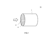
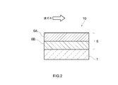
- FIG. 1 is a perspective view schematically showing an exhaust gas purifying catalyst according to one embodiment. It is a sectional view showing typically a catalyst layer of an exhaust gas purifying catalyst concerning one embodiment.
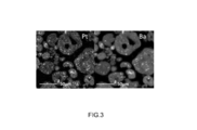
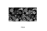
- 3 is an image showing element mapping results of Ba and Pt in a FE-EPMA area analysis (256 ⁇ 256 pixels) of the Pt-containing powder material used in Example 1.
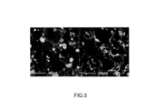
- 5 is an image showing element mapping results of Ba and Pt in a FE-EPMA area analysis (256 ⁇ 256 pixels) of the Pt-containing powder material used in Comparative Example 1.
- 9 is an image showing element mapping results of Ba and Pt in a FE-EPMA area analysis (256 ⁇ 256 pixels) of the Pt-containing powder material used in Comparative Example 2.
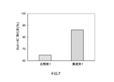
- 3 is a graph comparing the HC purification performance of the Pt-containing powder material used in Example 1 with the exhaust gas purification catalyst of Comparative Example 1.
- 5 is a graph comparing the HC purification performance of the exhaust gas purifying catalyst of Example 1 with the exhaust gas purifying catalyst of Comparative Example 1. Is a graph comparing the catalyst of Comparative Example 1 and the NO x purification performance of the exhaust gas purifying catalyst of Example 1.
- FIGS. 1 and 2 described later are schematically shown for understanding the contents of the present invention, and the dimensional relationships (length, width, thickness, etc.) in each drawing are the actual dimensional relationships. It does not reflect that.
- the sulfate of the alkaline earth metal having the above-mentioned properties has a high degree of activity in at least a part of the catalyst layer (that is, a pre-designed alkaline earth metal supporting region in the catalyst layer).
- An exhaust gas purifying catalyst characterized by being provided in a dispersed state, and other configurations are not particularly limited.
- the exhaust gas purifying catalyst disclosed herein can be used in various types of internal combustion engines, in particular, automobile engine exhaust systems (exhaust pipes) by appropriately selecting the types of carriers and base materials described below and molding them into desired shapes according to the applications. ).
- exhaust gas purifying catalyst of the present invention is applied to a three-way catalyst provided in an exhaust pipe of an automobile gasoline engine. It is not intended to be limited to such applications.
- ⁇ Substrate> As the base material constituting the skeleton of the exhaust gas purifying catalyst disclosed herein, various materials and forms conventionally used for this type of application can be adopted. For example, ceramics such as cordierite and silicon carbide (SiC) having high heat resistance are suitable. Alternatively, an alloy (such as stainless steel) base material can be used. The shape may be the same as that of a conventional exhaust gas purifying catalyst. As an example, as in an exhaust gas purifying catalyst 10 shown in FIG. 1, a honeycomb substrate 1 having a cylindrical outer shape is provided with through holes (cells) 2 as exhaust gas channels in the cylinder axis direction. One in which exhaust gas can contact a partition wall (rib wall) 4 that partitions the cell 2 can be used.
- rib wall partition wall
- the shape of the substrate 1 can be a foam shape, a pellet shape, or the like in addition to the honeycomb shape.
- a so-called wall-through type (also referred to as a wall-flow type) base material in which exhaust gas flows from one entry-side cell through a cell partition to the other exit-side cell may be used.
- the outer shape of the entire base material may be an elliptical cylindrical shape or a polygonal cylindrical shape instead of the cylindrical shape.
- Pt is used as a catalyst metal provided in the catalyst layer of the exhaust gas purifying catalyst disclosed herein.
- Pt is preferably used as fine particles having a sufficiently small particle size from the viewpoint of increasing the contact area with the exhaust gas.
- the average particle size (for example, the average value of the particle size obtained by TEM observation, or preferably the average value based on the X-ray diffraction method) is about 1 nm or more and 15 nm or less, and 10 nm or less and 7 nm or less. It is particularly preferable that the thickness be 5 nm or less.
- the loading ratio of the catalyst metal is not particularly limited, but is usually 2% by mass or less, for example, 0.05% by mass or more and 2% by mass or less. Yes, it is preferable that it is about 0.2% by mass to 1% by mass. If the loading is less than the above range, it is difficult to obtain the catalytic effect of Pt. If the loading ratio is too large, the cost will be disadvantageous.
- the porous carrier that forms the catalyst layer and supports Pt and other components for example, alkaline earth metal
- the same inorganic compounds as those used in conventional exhaust gas purifying catalysts are used.
- a porous support having a relatively large specific surface area is preferably used.
- Preferable examples include alumina (Al 2 O 3 ), zirconia (ZrO 2 ), ceria (CeO 2 ), silica (SiO 2 ), titania (TiO 2 ), and solid solutions thereof (eg, ceria-zirconia composite oxide). (CZ composite oxide) or a combination thereof.
- a heat-resistant inorganic compound such as alumina or zirconia is used as a carrier or a non-supporting material (that is, the structure of the catalyst layer not supporting Pt or alkaline earth metal). It is preferable to include the catalyst component in the catalyst layer.
- the particles of the carrier or unsupported body should have a specific surface area of 50 to 500 m 2 / g (for example, 200 to 400 m 2 / g) for heat resistance and structural stability. Preferred from a viewpoint.
- the average particle size of the carrier particles based on TEM observation is preferably about 1 nm or more and 500 nm or less (more preferably 5 nm or more and 300 nm or less).
- the catalyst metal content per 1 L of the catalyst volume be about 0.1 to 5 g / L, and 0.2 to 2 g / L. The degree is preferred. If the catalyst metal content is too large, it is not preferable in terms of cost, and if it is too small, it is not preferable because the exhaust gas purification ability is low.
- the catalyst volume when the catalyst volume is 1 L, the bulk volume includes the internal void (cell) volume (that is, includes the catalyst layer formed in the void (cell)) in addition to the pure volume of the base material. Is 1L.
- the catalyst layer formed on the base material, as a place for purifying the exhaust gas, is the main component of the exhaust gas purification catalyst, but in the exhaust gas purification catalyst disclosed herein, as described above, At least a part (or all) constitutes an alkaline earth metal supporting region.
- the “alkaline earth metal supporting region” refers to a part or the whole of a catalyst layer including a porous carrier, Pt, and an alkaline earth metal sulfate (such as barium sulfate and strontium sulfate).
- part of the catalyst layer refers to one section that can function as an exhaust gas purifying catalyst, and is not functionally a single section such as several to several tens of carrier particles. This is a term that does not mean a microscopic part.
- the arrangement (distribution) and the like of Pt carried on the catalyst layer can be appropriately set according to various purposes, similarly to the determination of the alkaline earth metal carrying region.
- the type of the carrier and the type and content ratio of the catalyst metal carried on the carrier can be different between the upper layer 6A and the lower layer 6B as in the conventional product. More specifically, for example, as in the case of a catalyst layer 6 shown in FIG.
- Either one or both of the adjacent lower layer 6B and the upper layer 6A constituting the surface layer portion of the catalyst layer 6 can be formed as an alkaline earth metal supporting region.
- a part of the upstream (or downstream) (for example, 10 vol% or more of the whole) is alkaline earth metal along the direction in which the exhaust gas flows. It may be a carrying area.
- a catalyst layer having Rh as a catalyst metal is further provided on the downstream side of the catalyst layer having the alkaline earth metal supporting region where exhaust gas flows.
- barium (Ba), strontium (Sr), and calcium (Ca) are mentioned as an alkaline earth metal element which constitutes a suitable sulfate contained in the alkaline earth metal supporting region.
- Ba and Sr are preferable, and Ba is particularly preferable, from the viewpoint of exhibiting a high function as a promoter component.
- Barium sulfate (BaSO 4 ) has a very high melting point and is stable, and further has a very low solubility in water, and thus is suitable as an alkaline earth metal to be supported on a carrier.
- auxiliary components can be arranged in the catalyst layer.
- a typical example is an oxygen storage / release component (Oxygen Storage Component: OSC).
- OSC oxygen Storage Component
- As the OSC material use of zirconium oxide (zirconia), cerium oxide (ceria), zeolite, or the like is preferable. Further, from the viewpoint of high heat resistance and occlusion / release speed, it is preferable to use the above ceria-zirconia composite oxide (CZ composite oxide) as an OSC material.
- CZ composite oxide ceria-zirconia composite oxide
- the alkaline earth metal sulfate supported on the porous carrier has an average particle size based on the X-ray diffraction method of 30 nm or less.
- Such an alkaline earth metal component having a fine average particle size can exhibit particularly high performance as a promoter component.
- ⁇ Pearson's correlation coefficient> Regarding the dispersibility of the alkaline earth metal in the alkaline earth metal supporting region of the exhaust gas purifying catalyst disclosed herein, regarding the cross section of the alkaline earth metal supporting region of the catalyst layer 6, Pixel size 0.34 ⁇ m ⁇ 0.34 ⁇ m; Number of measured pixels 256 ⁇ 256; Surface analysis by FE-EPMA was performed under the following conditions, and the characteristic X-ray intensity ( ⁇ : cps) of the alkaline earth metal element (Ae) and the characteristic X-ray intensity ( ⁇ : cps) of Pt were determined for each pixel. measured, when Pearson's correlation coefficient was calculated using the ⁇ and ⁇ in the obtained each pixel was R Ae / Pt, the value of R Ae / Pt is 0.5 or more.
- the alkaline earth metal When the alkaline earth metal is highly dispersed and supported inside the carrier (particularly, inside the secondary particles of the carrier), the correlation between the location of Pt and the location of the alkaline earth metal is so high that the correlation is recognized. Pt and the alkaline earth metal become closer. A state in which the alkaline earth metal is highly dispersed inside the carrier (particularly inside the secondary particles of the carrier) and Pt and the alkaline earth metal are brought close to each other is obtained by the value of RAe / Pt being 0.5 or more. be able to. When the value of RAe / Pt is 0.5 or more, the effect of the alkaline earth metal as a promoter component can be exhibited at a high level. In particular, since the alkaline earth metal is close to Pt, HC poisoning of Pt is suppressed by electron donation from the alkaline earth metal, and the HC purification performance in a Rich atmosphere is improved.
- the value of RAe / Pt is preferably 0.6 or more, and more preferably 0.7 or more.
- Pearson's correlation coefficient: R Ae / pt is obtained by performing a surface analysis by FE-EPMA, and determining the characteristic X-ray intensity ( ⁇ : cps) of the alkaline earth metal element (Ae) and the characteristic X-ray intensity (Pt) of Pt ( ⁇ : cps) can be measured for each pixel, and can be calculated using ⁇ and ⁇ at each obtained pixel.
- FE Field Emission
- -EPMA Electro Probe Micro Analysis
- the calculation of the correlation coefficient R Ae / Pt based on the equation (1) can be derived by using commercially available general spreadsheet software without performing particularly difficult calculation processing by hand. For example, it can be easily derived by using the CORREL function function of Excel (trademark) manufactured by Microsoft Corporation.
- the data collection for calculating the correlation coefficient can be performed by operating the surface analysis by FE-EPMA according to the manual of a commercially available device. Briefly, first, a catalyst layer (alkaline earth metal supporting region) of an exhaust gas purifying catalyst for surface analysis is cut out and used, or a cross section is formed by polishing the surface of the powder material to obtain a conductive material ( Typically, carbon) is vapor-deposited to obtain a sample for EPMA analysis. Then, surface analysis is performed using a commercially available device (for example, an electron beam microanalyzer such as JXA-8530F manufactured by JEOL Ltd.).
- a commercially available device for example, an electron beam microanalyzer such as JXA-8530F manufactured by JEOL Ltd.
- the pixel (section) size can be 0.34 ⁇ m ⁇ 0.34 ⁇ m
- the number of measurement pixels (sections) can be 200 ⁇ 200 or more, for example, 256 ⁇ 256.
- the measurement conditions are not particularly limited because they depend on the analyzer, but as typical measurement conditions, Acceleration voltage: 10 kV to 30 kV (for example, 20 kV), Irradiation current: 50 nA to 500 nA (for example, 100 nA); Minimum probe diameter: 500 nm or less (for example, 100 nm), Unit measurement time: 40 ms to 100 ms (for example, 50 ms), Is mentioned.
- the results of surface analysis by FE-EPMA can be displayed as element mapping using an application (computer software) attached to a commercially available device (see the drawings described later).
- the method for producing an exhaust gas purifying catalyst according to the present embodiment includes, on a substrate, a porous carrier composed of an inorganic compound, Pt supported on the porous carrier, and at least supported on the porous carrier.
- the raw material suspension is dried and further calcined to prepare a powder material in which the porous carrier, Pt, and an alkaline earth metal sulfate are mixed.
- a slurry for forming an alkaline earth metal-supported region containing at least the powder material and an aqueous solvent is prepared. Thereafter, the alkaline earth metal supporting region is formed on the base material using the slurry.
- examples of the inorganic compound constituting the porous carrier are the same as those described above.
- examples of the precursor for depositing Pt include a water-soluble complex or salt of Pt.
- examples of the water-soluble compound of an alkaline earth metal include various salts, for example, hydroxides, halides, acetates, nitrates, and nitrites of Ba, Sr or Ca.
- Those with high water solubility eg, acetates, nitrites, and iodides, particularly barium acetate, barium nitrite, and barium iodide are particularly preferred.
- the S-containing water-soluble organic compound is not particularly limited as long as it can form a sulfate of an alkaline earth metal in the process of preparing the above-mentioned raw material suspension, drying and baking.
- Preferred examples include taurine (2-aminoethanesulfonic acid), aminobenzenesulfonic acid, aminomethanesulfonic acid, 1-amino-2-naphthol-4-sulfonic acid, cysteic acid, methionine, cystine, dimethyl sulfate, dimethylsulfide, Examples thereof include dimethyl trisulfide, 2-mercaptoethanol, diphenyl sulfide, dithiothreitol, allyl disulfide, sulfolane, furfuryl mercaptan, dipropyl disulfide, dimethyl sulfone, dimethyl sulfoxide, and the like.
- a water-soluble organic substance having the following is preferred because of its high reactivity for the production of sulfate.
- those having a basic group such as an amino group (—NH 2 ) are preferable because they have a high effect of preventing a decrease in the pH of the raw material suspension (that is, strong acidification).
- taurine (2-aminoethanesulfonic acid), aminobenzenesulfonic acid, aminomethanesulfonic acid, 1-amino-2-naphthol-4-sulfonic acid, cysteic acid, methionine, and cystine are particularly preferred.
- the above-mentioned various materials are mixed with an aqueous solvent (typical).
- aqueous solvent typically, pure water or deionized water
- Pt particles or a precursor for precipitating Pt are suspended in water, and the obtained suspension is mixed with inorganic compound particles (powder) constituting the porous carrier, stirred, and further mixed with alkali.
- the water-soluble compound of an earth metal is added and stirred well for a predetermined time (for example, 10 minutes to 60 minutes), and then the S-containing water-soluble organic compound is added and sufficiently added at a temperature range of about 90 to 130 ° C.
- a predetermined time for example, 10 minutes to 60 minutes
- drying is performed for 6 hours or more, preferably 8 hours or more
- firing is performed in a temperature range of about 400 to 600 ° C. for several hours (for example, about 1 to 3 hours).
- the porous carrier particles prior to the formation of the catalyst layer (including the alkaline earth metal-supported region), the porous carrier particles (secondary particles) are highly dispersed on the outer surface and inside (in the pores).
- the obtained powder material can be subjected to a pulverizing treatment as needed to adjust to a desired particle size (for example, a particle size of 10 ⁇ m or less).
- the particle size of the alkaline earth metal sulfate carried on the outer surface and in the pores of the porous carrier particles can be made much smaller than before.
- fine alkaline earth metal sulfates having an average particle size based on X-ray diffraction of 30 nm or less (for example, 10 nm or more and 30 nm or less), preferably 20 nm or less.
- barium sulfate particles can be supported in a highly dispersed state on the outer surface and in the pores of the porous carrier particles. According to the above process, it is possible to realize a highly dispersed state in which the correlation coefficient: R Ae / Pt is 0.5 or more, further 0.6 or more, and further 0.7 or more. it can.
- a slurry for forming a catalyst layer (alkaline earth metal supporting region) is prepared using the obtained powder material (which has been appropriately pulverized).
- the preparation of such a slurry may be the same as the case of forming a catalyst layer of a conventional exhaust gas purifying catalyst, and there is no particular limitation.
- the upper layer 6A which is an alkaline-earth metal supporting region, is formed on the base material 1 of the exhaust gas purifying catalyst 10 in which the structure of the upper and lower two-layer structure type catalyst layer 6 shown in FIG.
- a lower layer forming slurry containing a catalyst metal component (a solution containing a catalyst metal ion other than Pt (eg, Rh)) and a desired carrier powder (alumina, zirconia, OSC material composed of CZ composite oxide, etc.)
- a catalyst metal component a solution containing a catalyst metal ion other than Pt (eg, Rh)
- a desired carrier powder alumina, zirconia, OSC material composed of CZ composite oxide, etc.
- the honeycomb substrate 1 is coated by a wash coat method or the like.
- an alkaline earth containing the powder material prepared above and, if necessary, a carrier powder not supporting an alkaline earth metal for example, an OSC material such as alumina, zirconia, or CZ composite oxide.
- the surface of the lower layer 6B is laminated and coated with the slurry for forming the metal supporting region by a known wash coating method or the like.
- the lower layer forming slurry is coated on the honeycomb substrate 1 and then dried and fired at a predetermined temperature and time to form the lower layer first, and then the alkaline earth
- a process in which the slurry for forming a metal-like supporting region is coated on the surface of the lower layer, followed by drying and firing to form an upper layer of the catalyst layer, and a two-stage firing process may be employed.
- the firing conditions of the wash-coated slurry vary depending on the shape and size of the base material or the carrier, and thus are not particularly limited. Typically, the firing is performed at about 400 to 1000 ° C. for about 1 to 5 hours. It is possible to form the catalyst layer in the target alkaline earth metal supporting region and other regions.
- the drying conditions before firing are not particularly limited, but drying at a temperature of 80 to 300 ° C. for about 1 to 12 hours is preferable.
- a binder should be contained in the slurry so that the slurry can be appropriately adhered to the surface of the base material 1 and, in the case of a laminated catalyst layer, to the surface of the lower layer 6B. Is preferred.
- the binder for this purpose, for example, use of alumina sol, silica sol or the like is preferable.
- the viscosity of the slurry may be appropriately adjusted so that the slurry can easily flow into the cells 2 of the base material (for example, the honeycomb base material) 1.
- ⁇ Test Example 1 Preparation of exhaust gas purifying catalyst>
- a cylindrical honeycomb substrate having a diameter of 103 mm and a total length of 105 mm as shown in FIG. 1 that is, a cordierite honeycomb substrate having a catalyst volume of 0.875 L
- An exhaust gas purifying catalyst having such a two-layer catalyst layer was produced as follows.
- Example 1 17.5 g of dinitrodiammineplatinum in Pt amount was added to 1 L of pure water and stirred to prepare a suspension. After adding 740 g of alumina to this suspension, 72 g of barium acetate was added and stirred. Thereafter, 70 g of taurine was added and stirred to prepare a slurry-like raw material suspension. This raw material suspension was dried at 110 ° C. for 8 hours or more, and subsequently calcined at 500 ° C. for 2 hours. Thereafter, a suitable pulverizing treatment was performed until the particle diameter became 10 ⁇ m or less, thereby producing a Pt-containing powder material.
- the above-prepared Pt-containing powder material 1800 g of a CZ composite oxide powder having a Ce content of 30% by weight, and 87 g of an alumina binder were added to 3.6 L of pure water, and the mixture was added using a magnetic ball mill.
- the slurry for upper layer formation was prepared by performing wet grinding.
- 5.6 g of rhodium nitrate in Rh amount was suspended in 0.9 L of pure water.
- 803 g of zirconia powder was added, dried, and subsequently calcined at 500 ° C. for 2 hours. Thereafter, an appropriate pulverization treatment was performed until the particle diameter became 10 ⁇ m or less, thereby producing a Rh-containing powder material.
- Rh-containing powder material 415 g of alumina powder, 413 g of CZ composite powder having a Ce content of 20% by weight, and 61 g of alumina binder were added to 2.3 L of pure water, and wet-processed using a magnetic ball mill. By grinding, a slurry for forming a lower layer was prepared.
- a wash coat is applied to the base material using the slurry for forming the lower layer, and dried at 150 ° C. for about 1 hour to form a lower layer (non-fired coat layer) on the surface of the base material (the rib wall surface in the cell). did.
- a wash coat was applied to the substrate using the slurry for forming an upper layer, and dried at 150 ° C. for about 1 hour to form an upper layer (non-fired coat layer) on the surface of the lower layer. Thereafter, baking was performed at 500 ° C. for 1 hour to obtain an exhaust gas purifying catalyst on which a catalyst layer composed of upper and lower layers (coat amount was 220 g / L for both upper and lower layers) was formed.
- Example 2 An exhaust gas purifying catalyst was obtained in the same manner as in Example 1 except that the raw material suspension was dried at 30 ° C. for 48 hours instead of drying the raw material suspension at 110 ° C. for 8 hours or more when producing the Pt-containing powder material.
- Example 2 An exhaust gas purifying catalyst was obtained in the same manner as in Example 1 except that when preparing the Pt-containing powder material, 74 g of ammonium sulfate as an inorganic compound was used instead of 70 g of taurine as a Ba fixing material.
- ⁇ Test Example 2 Confirmation of barium sulfate dispersibility of Pt-containing powder material by FE-EPMA> Using a FE-EPMA device (JXA-8530F) manufactured by JEOL Ltd. as per the manual, surface analysis was performed on each Pt-containing powder material produced in Test Example 1. That is, the surface of each powder material of a predetermined amount was polished to obtain a cross section, and carbon as a conductive substance was deposited using a commercially available carbon coater (Vacuum Device Co., Ltd .: VC-100W). Then, a region corresponding to the Pt-containing powder material on the carbon vapor-deposited surface was appropriately determined, and the region was subjected to surface analysis by FE-EPMA.
- JXA-8530F FE-EPMA device manufactured by JEOL Ltd.
- the measurement conditions are Pixel size: 0.34 ⁇ m ⁇ 0.34 ⁇ m, Measurement pixels: 256 ⁇ 256, Acceleration voltage: 20 kV, Irradiation current: 100 nA, Probe diameter: set to the minimum under the relevant measurement conditions, Unit measurement time: 50 ms / 1 pixel, Measurement magnification: ⁇ 1000 And The characteristic X-ray intensity of Ba element ( ⁇ : cps) and the characteristic X-ray intensity of Pt ( ⁇ : cps) were measured for each pixel.
- the threshold value of the X-ray intensity per pixel (area) is set to 15 cps for Ba and 5 cps for Pt, and the pixels showing the intensity lower than the threshold value are data for calculating the correlation coefficient. Excluded from.
- FIGS. 3 to 6 show data (images) on element mapping of Ba and S for the sample of Example 1 and the samples of Comparative Examples 1 and 2.
- ⁇ Test Example 3 Ba dissolution test> Each Pt-containing powder material produced in Test Example 1 was suspended in pure water, and the amount of Ba eluted when an acid was added was measured by an ICP emission spectrometer (Agilent 5110 ICP-OES) manufactured by Agilent. The Ba elution rate was determined. Table 1 shows the results.
- Comparative Example 1 and Comparative Example 2 the values of the correlation coefficient RBa / Pt are -0.128 and 0.060, respectively, and there is no correlation between the positions of Pt and Ba. From this, it can be seen that in Example 1, as compared with Comparative Examples 1 and 2, Ba is not only highly dispersed but also Pt and Ba are close to each other. In Comparative Example 3, the value of the correlation coefficient RBa / Pt was 0.720, and a strong correlation was observed between the positions of Pt and Ba. However, the Ba elution rate was 70%, and Ba was immobilized. could not.
- HC purification rate measurement of Pt-containing powder material Pellets of the Pt-containing powder material used in Example 1 and Comparative Example 1 were prepared, and subjected to Rich / Lean durability using a tubular furnace. Thereafter, the HC purification rate was measured 3 minutes after the air-fuel ratio was switched from Lean to Rich using an activity evaluation device (CATA5000) manufactured by Best Sokki Co., Ltd. FIG. 7 shows the results.
- CA5000 activity evaluation device manufactured by Best Sokki Co., Ltd.
- FIG. 7 shows the results.
- Example 1 As shown in FIG. 7, the Pt-containing powder material used in Example 1 showed a much higher HC purification rate.
- Ba is highly dispersed and supported on the carrier secondary particles, and Pt and Ba are brought close to each other so that a correlation is found between the positions of Pt and Ba. For this reason, it is considered that HC poisoning was suppressed by the electron donation of Ba to Pt, and the HC purification performance in the Rich atmosphere was improved.
- Example 5 Evaluation of Rh-containing catalyst layer by FE-EPMA>
- the laminated portion of the upper catalyst layer and the lower catalyst layer of the exhaust gas purifying catalyst produced in Example 1 was cut out and the cross section was polished.
- Carbon as a conductive substance was vapor-deposited on the cross section using a commercially available carbon coater (Vacuum Device Co., Ltd .: VC-100W).
- the cross section was subjected to surface analysis using the above-mentioned FE-EPMA apparatus (JXA-8530F).
- the measurement conditions are Pixel size: 0.85 ⁇ m ⁇ 0.85 ⁇ m, Measurement pixels: 256 ⁇ 256, Acceleration voltage: 20 kV, Irradiation current: 100 nA, Probe diameter: set to the minimum under the relevant measurement conditions, Unit measurement time: 50 ms / 1 pixel, Measurement magnification: ⁇ 400 And Then, the intensity of the characteristic X-ray of the Ba element ( ⁇ : cps) and the intensity of the characteristic X-ray of Rh ( ⁇ : cps) were measured for each pixel.
- the threshold value of the X-ray intensity per pixel (area) is set to 15 cps for Ba and 5 cps for Rh, and the pixels showing the intensity lower than the threshold value are the data for calculating the correlation coefficient.
- the correlation coefficient RBa / Rh of the obtained data was determined using the CORREL function function of spreadsheet software "Excel". As a result, the correlation coefficient RBa / Rh was 0.023, and no correlation was found between the positions of Ba and Rh in the catalyst. From this, in the exhaust gas purifying catalyst of Example 1, Ba is fixed in the upper layer which is the alkaline earth metal supporting region containing Pt, so that Ba present in the upper layer and Rh present in the lower layer are reduced. It can be seen that the contact of the object was prevented.
- Example 6 Measurement of Purification Rate of Exhaust Gas Purification Catalyst>
- the exhaust gas purifying catalysts produced in Example 1 and Comparative Example 1 were installed in an exhaust system of an engine, and the engine was operated to perform durability. After such durability test were measured HC purification ratio and the NO x purification ratio after 3 minutes after switching on Rich fuel ratio of the gas mixture supplied to the engine from the Lean using the catalyst. The results are shown in FIGS.
- Example 1 As shown in the results of FIG. 8 and FIG. 9, the exhaust gas purifying catalyst of Example 1 showed much higher HC purification ratio and the NO x purification rate than the exhaust gas purifying catalyst of Comparative Example 1. The reason is considered as follows.
- Example 1 since Ba is highly dispersed and supported on the carrier secondary particles, Pt and Ba are brought close to each other such that a correlation is found between the positions of Pt and Ba. For this reason, HC poisoning is suppressed by the electron donation of Ba to Pt, and the HC purification performance in the Rich atmosphere is improved. Further, since Ba is immobilized, contact between Ba and Rh is prevented, and thereby, suppression of metalization of Rh by Ba is prevented. Furthermore, the poisoning of Rh is suppressed by reducing the amount of HC flowing into the downstream Rh-containing catalyst layer by improving the HC purification action of the upstream Pt-containing catalyst layer. Also improves purification performance of coexistence NO x from the above.
Landscapes
- Chemical & Material Sciences (AREA)
- Engineering & Computer Science (AREA)
- Chemical Kinetics & Catalysis (AREA)
- Materials Engineering (AREA)
- Organic Chemistry (AREA)
- Health & Medical Sciences (AREA)
- Combustion & Propulsion (AREA)
- Mechanical Engineering (AREA)
- General Engineering & Computer Science (AREA)
- Toxicology (AREA)
- Physics & Mathematics (AREA)
- Thermal Sciences (AREA)
- Ceramic Engineering (AREA)
- Biomedical Technology (AREA)
- Environmental & Geological Engineering (AREA)
- Analytical Chemistry (AREA)
- General Chemical & Material Sciences (AREA)
- Oil, Petroleum & Natural Gas (AREA)
- Catalysts (AREA)
- Exhaust Gas Treatment By Means Of Catalyst (AREA)
- Exhaust Gas After Treatment (AREA)
Abstract
本発明は、アルカリ土類金属を高度な分散状態で多孔質担体に担持させた排ガス浄化用触媒を提供する。本発明により提供される排ガス浄化用触媒の触媒層は、多孔質担体と、Ptと、当該多孔質担体に担持された少なくとも一種のアルカリ土類金属の硫酸塩とを備えるアルカリ土類金属担持領域を有しており、 当該領域の断面について、 ピクセルサイズ 0.34μm×0.34μm; 測定ピクセル数 256×256; の条件でFE-EPMAによる面分析を行い、前記アルカリ土類金属の元素(Ae)の特性X線の強度(α:cps)およびPtの特性X線の強度(β:cps)を各ピクセルについて測定し、得られた各ピクセルにおけるαおよびβを用いて算出したピアソンの相関係数RAe/Pt値が0.5以上であることを特徴とする。
Description
本発明は、内燃機関の排気系に設けられる排ガス浄化用触媒に関する。詳しくは、触媒金属として白金(Pt)を含み、さらに助触媒成分としてバリウム(Ba)、ストロンチウム(Sr)等のアルカリ土類金属を含む排ガス浄化用触媒に関する。なお、本出願は2018年10月4日に出願された日本国特許出願第2018-189365号に基づく優先権を主張しており、その出願の全内容は本明細書中に参照として組み入れられている。
自動車エンジン等の内燃機関から排出される排ガスから炭化水素(HC)、一酸化炭素(CO)、窒素酸化物(NOx)等の有害成分を酸化または還元反応によって除去するための排ガス浄化用触媒として、いわゆる三元触媒が用いられている。三元触媒としては、例えばアルミナ(Al2O3)、ジルコニア(ZrO2)等の無機酸化物からなる多孔質担体に、酸化触媒及び/又は還元触媒として機能する金属(典型的にはPt等の貴金属)を担持させたものが利用されている。
さらに、この種の排ガス浄化触媒には、排ガス浄化機能を向上させ得る助触媒成分が用いられている。例えば、以下の特許文献1,2には、触媒金属としてPtを、助触媒としてバリウム(Ba)、ストロンチウム(Sr)等のアルカリ土類金属を含む従来の排ガス浄化用触媒が記載されている。
さらに、この種の排ガス浄化触媒には、排ガス浄化機能を向上させ得る助触媒成分が用いられている。例えば、以下の特許文献1,2には、触媒金属としてPtを、助触媒としてバリウム(Ba)、ストロンチウム(Sr)等のアルカリ土類金属を含む従来の排ガス浄化用触媒が記載されている。
ところで、上述したようなアルカリ土類金属の助触媒としての効果を発揮するには、排ガス浄化用触媒の触媒層中においてアルカリ土類金属がPtの近傍に存在していることが必要である。そしてまた、排ガス浄化用触媒の全体において助触媒としての効果を発揮するには、Ptとともにアルカリ土類金属が高度に分散した状態で存在することが重要である。
しかしながら、従来の触媒層の形成技法によると、触媒層(アルカリ土類金属担持領域)中にアルカリ土類金属の偏在が生じており、高度な分散状態で多孔質担体の外表面および細孔内にアルカリ土類金属を担持させることができなかった。このことを換言すれば、触媒層(アルカリ土類金属担持領域)中において多孔質担体の外表面および細孔内に高度に分散した状態で担持されたPtの近傍に、アルカリ土類金属を同様に高分散状態で担持(固定)することができなかった。例えば、多孔質担体の外表面に大半のアルカリ土類金属が偏在するなどの不都合があった。
そこで本発明は、かかる従来の課題を解決するべく創出されたものであり、助触媒成分たるアルカリ土類金属を高度な分散状態で多孔質担体に担持させた排ガス浄化用触媒の提供と、そのような高分散な担持を実現し得る製法を提供することを目的とする。
しかしながら、従来の触媒層の形成技法によると、触媒層(アルカリ土類金属担持領域)中にアルカリ土類金属の偏在が生じており、高度な分散状態で多孔質担体の外表面および細孔内にアルカリ土類金属を担持させることができなかった。このことを換言すれば、触媒層(アルカリ土類金属担持領域)中において多孔質担体の外表面および細孔内に高度に分散した状態で担持されたPtの近傍に、アルカリ土類金属を同様に高分散状態で担持(固定)することができなかった。例えば、多孔質担体の外表面に大半のアルカリ土類金属が偏在するなどの不都合があった。
そこで本発明は、かかる従来の課題を解決するべく創出されたものであり、助触媒成分たるアルカリ土類金属を高度な分散状態で多孔質担体に担持させた排ガス浄化用触媒の提供と、そのような高分散な担持を実現し得る製法を提供することを目的とする。
本発明者は、助触媒たるBa等のアルカリ土類金属の触媒層中における存在形態について詳細に検討した。そして、Ba等のアルカリ土類金属を原料段階から水に不溶性の硫酸塩として使用すると、触媒層においてアルカリ土類金属の偏在を招き、高度な分散状態を実現できないことが確認された。また、Baの硝酸塩のような水溶性化合物を含む原料スラリーを使用し、硫酸や硫酸アンモニウム溶液を当該スラリーに供給してBa等のアルカリ土類金属の硫酸塩(不溶体)を生成する場合には、その後の乾燥および焼成段階において当該原料スラリーのpHが変化して酸性に偏りすぎ、結果、高分散状態を維持できずにアルカリ土類金属の偏在が生じ、やはり高度な分散状態は実現できなかった。
そこで、本発明者は、Ba等のアルカリ土類金属の原料段階から検討し、アルカリ土類金属の水溶性化合物を、ある種のS含有水溶性有機化合物と共存させた原料を用いることにより、触媒層(アルカリ土類金属担持領域)中においてPtとともに高度な分散状態でBa等のアルカリ土類金属硫酸塩を多孔質担体に配置(担持)することができることを見出し、本発明を完成するに至った。
そこで、本発明者は、Ba等のアルカリ土類金属の原料段階から検討し、アルカリ土類金属の水溶性化合物を、ある種のS含有水溶性有機化合物と共存させた原料を用いることにより、触媒層(アルカリ土類金属担持領域)中においてPtとともに高度な分散状態でBa等のアルカリ土類金属硫酸塩を多孔質担体に配置(担持)することができることを見出し、本発明を完成するに至った。
本発明によって、内燃機関の排気管に配置されて当該内燃機関から排出される排ガスの浄化を行う排ガス浄化用触媒が提供される。
即ち、ここで開示される排ガス浄化用触媒は、基材と、当該基材上に形成された触媒層とを備えている。かかる触媒層は、
無機化合物から構成される多孔質担体と、
当該多孔質担体上に担持されたPtと、
当該多孔質担体上に担持された、少なくとも一種のアルカリ土類金属の硫酸塩と、
を備えるアルカリ土類金属担持領域を有している。
そして、ここで開示される排ガス浄化用触媒は、上記触媒層のアルカリ土類金属担持領域の断面について、
ピクセル(区画)サイズ 0.34μm×0.34μm;
測定ピクセル(区画)数 256×256:
の条件でFE-EPMAによる面分析を行い、前記アルカリ土類金属の元素(Ae)の特性X線の強度(α:cps)およびPtの特性X線の強度(β:cps)を各ピクセルについて測定し、得られた各ピクセルにおけるαおよびβを用いて算出したピアソンの相関係数をRAe/Ptとしたとき、
当該RAe/Ptの値が0.5以上であることを特徴とする。
即ち、ここで開示される排ガス浄化用触媒は、基材と、当該基材上に形成された触媒層とを備えている。かかる触媒層は、
無機化合物から構成される多孔質担体と、
当該多孔質担体上に担持されたPtと、
当該多孔質担体上に担持された、少なくとも一種のアルカリ土類金属の硫酸塩と、
を備えるアルカリ土類金属担持領域を有している。
そして、ここで開示される排ガス浄化用触媒は、上記触媒層のアルカリ土類金属担持領域の断面について、
ピクセル(区画)サイズ 0.34μm×0.34μm;
測定ピクセル(区画)数 256×256:
の条件でFE-EPMAによる面分析を行い、前記アルカリ土類金属の元素(Ae)の特性X線の強度(α:cps)およびPtの特性X線の強度(β:cps)を各ピクセルについて測定し、得られた各ピクセルにおけるαおよびβを用いて算出したピアソンの相関係数をRAe/Ptとしたとき、
当該RAe/Ptの値が0.5以上であることを特徴とする。
ここで開示される排ガス浄化用触媒は、本発明によって提供される排ガス浄化用触媒製造方法(詳細は後述する。)により製造され得る触媒製品であり、上述のとおり、FE-EPMAによる面分析の結果に基づいて算出されたピアソンの相関係数(積率相関係数)であるRAe/Ptが0.5以上であることを特徴とする。
かかる相関係数RAe/Ptは、第1変数をFE-EPMAによる面分析におけるアルカリ土類金属元素(Ae)の特性X線強度(α)とし、第2変数を同じ面分析における多Ptの特性X線強度(β)としたとき、
RAe/Pt=(共分散)/(αの標準偏差×βの標準偏差)
で求められる相関係数である。
かかる相関係数RAe/Ptは、第1変数をFE-EPMAによる面分析におけるアルカリ土類金属元素(Ae)の特性X線強度(α)とし、第2変数を同じ面分析における多Ptの特性X線強度(β)としたとき、
RAe/Pt=(共分散)/(αの標準偏差×βの標準偏差)
で求められる相関係数である。
本構成の排ガス浄化用触媒では、触媒層のアルカリ土類金属担持領域において、Ptとアルカリ土類金属元素存在位置(分布)との間に高い相関があること、換言すれば、多孔質担体粒子の全体(即ち担体粒子の外表面および内部(細孔内)の両方)にわたって高度に分散した状態でアルカリ土類金属(硫酸塩)が存在していることを特徴とする。これにより、触媒層のアルカリ土類金属担持領域においてPt粒子の近傍に高頻度でアルカリ土類金属が存在し得るため、当該アルカリ土類金属の助触媒成分としての作用効果を高レベルに発揮させることができる。特に、アルカリ土類金属がPtと近接しているため、アルカリ土類金属からの電子供与によるPtのHC被毒抑制が起こり、Rich雰囲気時のHC浄化性能が向上する。
ここで開示される排ガス浄化用触媒の好適な他の一態様では、上記算出したピアソンの相関係数RAe/Ptの値が0.7以上であることを特徴とする。
RAe/Ptの値が0.7以上で示されるように、本構成の排ガス浄化用触媒は、アルカリ土類金属成分の分散性が高い。このため、助触媒成分としての性能(機能)を触媒層(アルカリ土類金属担持領域)中において高レベルに発揮させることができる。
RAe/Ptの値が0.7以上で示されるように、本構成の排ガス浄化用触媒は、アルカリ土類金属成分の分散性が高い。このため、助触媒成分としての性能(機能)を触媒層(アルカリ土類金属担持領域)中において高レベルに発揮させることができる。
多孔質担体に担持されたアルカリ土類金属硫酸塩のX線回折法に基づく平均粒径が30nm以下であることが特に好ましい。かかる微細な平均粒径のアルカリ土類金属成分は、助触媒成分として特に高い性能を発揮し得る。
また、ここで開示される排ガス浄化用触媒の好適な一態様では、上記の触媒層の排ガスが流れる方向の下流側に、Rhを触媒金属とする触媒層をさらに有する。
このとき、Rhを触媒金属とする触媒層への流入HC量が減少することになるため、RhのHC被毒を抑制することができる。また、アルカリ土類金属が硫酸塩であり、固定されているため、RhとBa等のアルカリ土類金属(特にBa)とが接触することを防ぎ、BaによるRhのメタル化抑制を防止することができる。このため、排ガス浄化用触媒のRich雰囲気時の共存NOxの浄化作用を向上させることができる。
このとき、Rhを触媒金属とする触媒層への流入HC量が減少することになるため、RhのHC被毒を抑制することができる。また、アルカリ土類金属が硫酸塩であり、固定されているため、RhとBa等のアルカリ土類金属(特にBa)とが接触することを防ぎ、BaによるRhのメタル化抑制を防止することができる。このため、排ガス浄化用触媒のRich雰囲気時の共存NOxの浄化作用を向上させることができる。
また、ここで開示される排ガス浄化用触媒の好適な一態様では、上記アルカリ土類金属硫酸塩として少なくとも硫酸バリウム(BaSO4)を有していることを特徴とする。
かかる構成の排ガス浄化用触媒によると、高度に分散したバリウム成分(硫酸バリウム)によって、NOxを安定的に一時的に吸蔵することができるとともに、当該成分に一時的に吸蔵されたNOx成分をPtにより効果的に還元浄化処理することができる。また、バリウム成分が高度に分散して担体に担持されることにより、NOx還元作用を向上させることができる。したがって、本構成の排ガス浄化用触媒は、高性能なNOx浄化触媒として好適に採用することができる。
かかる構成の排ガス浄化用触媒によると、高度に分散したバリウム成分(硫酸バリウム)によって、NOxを安定的に一時的に吸蔵することができるとともに、当該成分に一時的に吸蔵されたNOx成分をPtにより効果的に還元浄化処理することができる。また、バリウム成分が高度に分散して担体に担持されることにより、NOx還元作用を向上させることができる。したがって、本構成の排ガス浄化用触媒は、高性能なNOx浄化触媒として好適に採用することができる。
また、本発明は、上記目的を実現するべく、ここで開示される排ガス浄化用触媒を好適に製造し得る方法を提供する。即ち、ここで開示される製造方法は、
内燃機関の排気管に配置されて当該内燃機関から排出される排ガスの浄化を行う排ガス浄化用触媒を製造する方法であって、
基材上に、
無機化合物から構成される多孔質担体と、
当該多孔質担体に担持されたPtと、
当該多孔質担体に担持された少なくとも一種のアルカリ土類金属の硫酸塩と、
を備えるアルカリ土類金属担持領域を少なくとも一部に有する触媒層を形成する工程、および
上記触媒層が形成された基材を焼成する工程、
を包含する方法である。
そして、ここで開示される製造方法では、上記触媒層の形成工程において、
(1)以下の成分:
上記多孔質担体を構成する無機化合物粒子;
Pt粒子、または、Ptを析出させるための前駆物質;
上記アルカリ土類金属の水溶性化合物;および
構成元素としてSを含有し、上記アルカリ土類金属の硫酸塩を生成可能なS含有水溶性有機化合物;
を水系溶媒と混合し、原料懸濁物を調製すること、
(2)上記原料懸濁物を乾燥し、さらに焼成することによって、上記多孔質担体とPtとアルカリ土類金属の硫酸塩とが混在する粉末材料を調製すること、
(3)少なくとも上記粉末材料と水系溶媒を含むアルカリ土類金属担持領域形成用スラリーを調製すること、および
(4)上記スラリーを用いて上記基材上に上記アルカリ土類金属担持領域を形成すること、
を包含する。
内燃機関の排気管に配置されて当該内燃機関から排出される排ガスの浄化を行う排ガス浄化用触媒を製造する方法であって、
基材上に、
無機化合物から構成される多孔質担体と、
当該多孔質担体に担持されたPtと、
当該多孔質担体に担持された少なくとも一種のアルカリ土類金属の硫酸塩と、
を備えるアルカリ土類金属担持領域を少なくとも一部に有する触媒層を形成する工程、および
上記触媒層が形成された基材を焼成する工程、
を包含する方法である。
そして、ここで開示される製造方法では、上記触媒層の形成工程において、
(1)以下の成分:
上記多孔質担体を構成する無機化合物粒子;
Pt粒子、または、Ptを析出させるための前駆物質;
上記アルカリ土類金属の水溶性化合物;および
構成元素としてSを含有し、上記アルカリ土類金属の硫酸塩を生成可能なS含有水溶性有機化合物;
を水系溶媒と混合し、原料懸濁物を調製すること、
(2)上記原料懸濁物を乾燥し、さらに焼成することによって、上記多孔質担体とPtとアルカリ土類金属の硫酸塩とが混在する粉末材料を調製すること、
(3)少なくとも上記粉末材料と水系溶媒を含むアルカリ土類金属担持領域形成用スラリーを調製すること、および
(4)上記スラリーを用いて上記基材上に上記アルカリ土類金属担持領域を形成すること、
を包含する。
かかる構成の排ガス浄化用触媒製造方法では、アルカリ土類金属の水溶性化合物と上記のように規定されるS含有水溶性有機化合物とを担体成分(無機化合物粒子)ならびに触媒金属成分(Pt粒子またはPtの前駆体である化合物)とともに混合させた原料(懸濁物)をアルカリ土類金属担持領域形成用途に使用する。
調製した原料懸濁物では、アルカリ土類金属水溶性化合物とS含有水溶性有機化合物とがともに水系溶媒に溶解している。このとき、S含有水溶性有機化合物は、原料懸濁物のpHを急激に低下(即ち懸濁液の酸性化)させることが無く、アルカリ土類金属水溶性化合物とS含有水溶性有機化合物は、ともに水溶性を保ったまま、担体成分である無機化合物粒子(二次粒子)の内部(細孔内)にまで行き渡ることができる。
そして、調製した原料懸濁物を乾燥させ、焼成する。その過程において、含有成分であるアルカリ土類金属の水溶性化合物と上記S含有水溶性有機化合物とが反応し、不溶性のアルカリ土類金属硫酸塩が無機化合物粒子の内部および外部において形成され、その存在部位において固定される。
したがって、本構成の製造方法によると、多孔質担体粒子の全体(即ち担体粒子の外表面および内部(細孔内)の両方)にわたって高度に分散した状態でアルカリ土類金属が存在していることを特徴とするアルカリ土類金属担持領域を触媒層の全体又は一部に有する排ガス浄化用触媒を、好適に製造することができる。
調製した原料懸濁物では、アルカリ土類金属水溶性化合物とS含有水溶性有機化合物とがともに水系溶媒に溶解している。このとき、S含有水溶性有機化合物は、原料懸濁物のpHを急激に低下(即ち懸濁液の酸性化)させることが無く、アルカリ土類金属水溶性化合物とS含有水溶性有機化合物は、ともに水溶性を保ったまま、担体成分である無機化合物粒子(二次粒子)の内部(細孔内)にまで行き渡ることができる。
そして、調製した原料懸濁物を乾燥させ、焼成する。その過程において、含有成分であるアルカリ土類金属の水溶性化合物と上記S含有水溶性有機化合物とが反応し、不溶性のアルカリ土類金属硫酸塩が無機化合物粒子の内部および外部において形成され、その存在部位において固定される。
したがって、本構成の製造方法によると、多孔質担体粒子の全体(即ち担体粒子の外表面および内部(細孔内)の両方)にわたって高度に分散した状態でアルカリ土類金属が存在していることを特徴とするアルカリ土類金属担持領域を触媒層の全体又は一部に有する排ガス浄化用触媒を、好適に製造することができる。
ここで開示される排ガス浄化用触媒製造方法の好適な一態様では、S含有水溶性有機化合物として、スルホ基(-SO3H)、スルホニル基(-S(=O)2-)およびスルフィニル基(-S(=O)-)のうちの少なくとも一つの官能基を有する水溶性有機物が使用されることを特徴とする。
かかるSを含む官能基を有する有機化合物は、上記原料懸濁物を調製するためのS含有水溶性有機化合物として好ましい。
かかるSを含む官能基を有する有機化合物は、上記原料懸濁物を調製するためのS含有水溶性有機化合物として好ましい。
また、ここで開示される排ガス浄化用触媒製造方法の好適な他の一態様では、上記アルカリ土類金属の水溶性化合物として、Ba、SrおよびCaのうちから選択される何れかのアルカリ土類金属の酢酸塩、亜硝酸塩またはヨウ化物が使用されることを特徴とする。
かかる酢酸塩、亜硝酸塩またはヨウ化物は、良好な水溶性を有し、上記原料懸濁物を調製するためのアルカリ土類金属の水溶性化合物として好ましい。
かかる酢酸塩、亜硝酸塩またはヨウ化物は、良好な水溶性を有し、上記原料懸濁物を調製するためのアルカリ土類金属の水溶性化合物として好ましい。
以下、図面を適宜参照しつつ本発明の好適ないくつかの実施形態を説明する。なお、本明細書において特に言及している事項以外の事柄であって本発明の実施に必要な事柄は、当該分野における従来技術に基づく当業者の設計事項として把握され得る。本発明は、本明細書に開示されている内容と当該分野における技術知識とに基づいて実施することができる。なお、後述する図1~図2は、本発明の内容を理解するために模式的に示したものであり、各図における寸法関係(長さ、幅、厚さなど)は、実際の寸法関係を反映するものではない。
ここで開示される排ガス浄化用触媒は、上述した性状でアルカリ土類金属の硫酸塩が触媒層の少なくとも一部(即ち、触媒層中における予め設計されたアルカリ土類金属担持領域)において高度に分散した状態で備えられていることで特徴づけられる排ガス浄化用触媒であり、その他の構成は特に限定されない。ここで開示される排ガス浄化用触媒は、後述する担体、基材の種類を適宜選択し、用途に応じて所望する形状に成形することによって種々の内燃機関、特に自動車エンジンの排気系(排気管)に配置することができる。
以下の説明では、主として本発明の排ガス浄化用触媒を自動車のガソリンエンジンの排気管に設けられる三元触媒に適用することを前提として説明しているが、ここで開示される排ガス浄化用触媒をかかる用途に限定することを意図したものではない。
以下の説明では、主として本発明の排ガス浄化用触媒を自動車のガソリンエンジンの排気管に設けられる三元触媒に適用することを前提として説明しているが、ここで開示される排ガス浄化用触媒をかかる用途に限定することを意図したものではない。
<基材>
ここで開示される排ガス浄化用触媒の骨格を構成する基材としては、従来この種の用途に用いられる種々の素材及び形態のものを採用することができる。例えば、高耐熱性を有するコージェライト、炭化ケイ素(SiC)等のセラミックスが好適である。或いは、合金(ステンレス鋼等)製の基材を使用することができる。形状についても従来の排ガス浄化用触媒と同様でよい。一例として図1に示す排ガス浄化用触媒10のように、外形が円筒形状であるハニカム基材1であって、その筒軸方向に排ガス流路としての貫通孔(セル)2が設けられ、各セル2を仕切る隔壁(リブ壁)4に排ガスが接触可能となっているものが挙げられる。基材1の形状はハニカム形状の他にフォーム形状、ペレット形状などとすることができる。或いは、排ガスが一方の入り側セルからセル隔壁を通過して他方の出側セルに流れていく所謂ウォールスルー型(ウォールフロー型ともいう。)の基材であってもよい。また、基材全体の外形については、円筒形に代えて楕円筒形、多角筒形を採用してもよい。
ここで開示される排ガス浄化用触媒の骨格を構成する基材としては、従来この種の用途に用いられる種々の素材及び形態のものを採用することができる。例えば、高耐熱性を有するコージェライト、炭化ケイ素(SiC)等のセラミックスが好適である。或いは、合金(ステンレス鋼等)製の基材を使用することができる。形状についても従来の排ガス浄化用触媒と同様でよい。一例として図1に示す排ガス浄化用触媒10のように、外形が円筒形状であるハニカム基材1であって、その筒軸方向に排ガス流路としての貫通孔(セル)2が設けられ、各セル2を仕切る隔壁(リブ壁)4に排ガスが接触可能となっているものが挙げられる。基材1の形状はハニカム形状の他にフォーム形状、ペレット形状などとすることができる。或いは、排ガスが一方の入り側セルからセル隔壁を通過して他方の出側セルに流れていく所謂ウォールスルー型(ウォールフロー型ともいう。)の基材であってもよい。また、基材全体の外形については、円筒形に代えて楕円筒形、多角筒形を採用してもよい。
<白金(Pt)>
ここで開示される排ガス浄化用触媒の触媒層に備えられる触媒金属として、Ptが用いられる。
Ptは、排ガスとの接触面積を高める観点から十分に小さい粒径の微粒子として使用されることが好ましい。典型的には平均粒径(例えばTEM観察により求められる粒径の平均値、或いは、X線回折法に基づく平均値であることが好ましい。)は1nm以上15nm以下程度であり、10nm以下、7nm以下、更には5nm以下であることが特に好ましい。
かかる触媒金属の担持率(担体を100質量%としたときのPt含有率)は、特に限定されないが、通常2質量%以下、例えば0.05質量%以上2質量%以下であることが適当であり、0.2質量%以上1質量%以下程度であることが好ましい。担持率が上記範囲より少なすぎると、Ptによる触媒効果が得られにくい。かかる担持率が上記範囲より多すぎるとコスト面で不利となる。
ここで開示される排ガス浄化用触媒の触媒層に備えられる触媒金属として、Ptが用いられる。
Ptは、排ガスとの接触面積を高める観点から十分に小さい粒径の微粒子として使用されることが好ましい。典型的には平均粒径(例えばTEM観察により求められる粒径の平均値、或いは、X線回折法に基づく平均値であることが好ましい。)は1nm以上15nm以下程度であり、10nm以下、7nm以下、更には5nm以下であることが特に好ましい。
かかる触媒金属の担持率(担体を100質量%としたときのPt含有率)は、特に限定されないが、通常2質量%以下、例えば0.05質量%以上2質量%以下であることが適当であり、0.2質量%以上1質量%以下程度であることが好ましい。担持率が上記範囲より少なすぎると、Ptによる触媒効果が得られにくい。かかる担持率が上記範囲より多すぎるとコスト面で不利となる。
<担体>
触媒層を構成し、Ptならびにその他の成分(例えばアルカリ土類金属)を担持する多孔質担体としては、従来の排ガス浄化用触媒と同様の無機化合物が使用される。
比表面積(BET法により測定される比表面積。以下同じ。)がある程度大きい多孔質担体が好適に用いられる。好適なものとして、例えば、アルミナ(Al2O3)、ジルコニア(ZrO2)、セリア(CeO2)、シリカ(SiO2)、チタニア(TiO2)、それらの固溶体(例えばセリア-ジルコニア複合酸化物(CZ複合酸化物)、或いはそれらの組み合わせが挙げられる。
触媒層を構成し、Ptならびにその他の成分(例えばアルカリ土類金属)を担持する多孔質担体としては、従来の排ガス浄化用触媒と同様の無機化合物が使用される。
比表面積(BET法により測定される比表面積。以下同じ。)がある程度大きい多孔質担体が好適に用いられる。好適なものとして、例えば、アルミナ(Al2O3)、ジルコニア(ZrO2)、セリア(CeO2)、シリカ(SiO2)、チタニア(TiO2)、それらの固溶体(例えばセリア-ジルコニア複合酸化物(CZ複合酸化物)、或いはそれらの組み合わせが挙げられる。
排ガス浄化用触媒の熱安定性を高めるという観点からは、耐熱性のよいアルミナ、ジルコニア等の無機化合物を担体若しくは非担持体(即ち、Ptやアルカリ土類金属を担持させていない触媒層の構成成分をいう。以下同じ。)として触媒層に含ませることが好ましい。
担体又は非担持体の粒子(例えばアルミナ粉末やCZ複合酸化物粉末)としては、比表面積が50~500m2/g(例えば200~400m2/g)であることが耐熱性、構造安定性の観点から好ましい。また、担体粒子のTEM観察に基づく平均粒径は、1nm以上500nm以下(より好ましくは5nm以上300nm以下)程度であることが好ましい。
また、このような無機化合物(セラミックス)を担体として使用する場合、好ましくは触媒容積が1Lあたりの触媒金属含有量が0.1~5g/L程度が適当であり、0.2~2g/L程度が好ましい。触媒金属含有量が多すぎるとコスト的に好ましくなく、少なすぎると排ガス浄化能が低いために好ましくない。なお、本明細書において触媒容積が1Lというときは、基材の純容積に加えて内部の空隙(セル)容積を含む(即ち当該空隙(セル)内に形成された触媒層を含む)嵩容積が1Lであることをいう。
担体又は非担持体の粒子(例えばアルミナ粉末やCZ複合酸化物粉末)としては、比表面積が50~500m2/g(例えば200~400m2/g)であることが耐熱性、構造安定性の観点から好ましい。また、担体粒子のTEM観察に基づく平均粒径は、1nm以上500nm以下(より好ましくは5nm以上300nm以下)程度であることが好ましい。
また、このような無機化合物(セラミックス)を担体として使用する場合、好ましくは触媒容積が1Lあたりの触媒金属含有量が0.1~5g/L程度が適当であり、0.2~2g/L程度が好ましい。触媒金属含有量が多すぎるとコスト的に好ましくなく、少なすぎると排ガス浄化能が低いために好ましくない。なお、本明細書において触媒容積が1Lというときは、基材の純容積に加えて内部の空隙(セル)容積を含む(即ち当該空隙(セル)内に形成された触媒層を含む)嵩容積が1Lであることをいう。
<アルカリ土類金属担持領域>
基材上に形成される触媒層は、排ガスを浄化する場として、排ガス浄化用触媒の主体をなすものであるが、ここで開示される排ガス浄化用触媒においては、上記のとおり、触媒層の少なくとも一部(又は全部)が、アルカリ土類金属担持領域を構成する。
本明細書において「アルカリ土類金属担持領域」は、多孔質担体とPtとアルカリ土類金属硫酸塩(硫酸バリウム、硫酸ストロンチウム等)とを備える触媒層の一部又は全部をいう。ここで「触媒層の一部」とは、排ガス浄化用触媒として機能し得る一区画をいうのであって、例えば担体粒子数個~数十個のような機能的に一区画と呼べないような微視的な一部を意味しない用語である。
基材上に形成される触媒層は、排ガスを浄化する場として、排ガス浄化用触媒の主体をなすものであるが、ここで開示される排ガス浄化用触媒においては、上記のとおり、触媒層の少なくとも一部(又は全部)が、アルカリ土類金属担持領域を構成する。
本明細書において「アルカリ土類金属担持領域」は、多孔質担体とPtとアルカリ土類金属硫酸塩(硫酸バリウム、硫酸ストロンチウム等)とを備える触媒層の一部又は全部をいう。ここで「触媒層の一部」とは、排ガス浄化用触媒として機能し得る一区画をいうのであって、例えば担体粒子数個~数十個のような機能的に一区画と呼べないような微視的な一部を意味しない用語である。
触媒層に担持されるPtの配置(分布)、等についてもアルカリ土類金属担持領域の決定と同様、種々の目的に応じて適宜設定することができる。例えば、図2に示す積層構造の触媒層6において、従来品と同様、上層6Aと下層6Bとで担体の種類や当該担体に担持される触媒金属の種類や含有割合を異ならせることができる。
具体的に例えば、一例として図2に示す触媒層6のように、基材1上に形成された相互に内容の異なる上下二層を有する積層構造タイプの触媒層6の場合、基材1に近接する下層6Bと触媒層6の表層部分を構成する上層6Aのうちのいずれか一層若しくは両方をアルカリ土類金属担持領域として形成することができる。或いは、図示されるような積層構造若しくは単層構造の触媒層において、その排ガスが流れる方向に沿って、上流側(又は下流側)の一部(例えば全体の10vol%以上)をアルカリ土類金属担持領域としてもよい。
ここで、アルカリ土類金属担持領域を有する触媒層の排ガスが流れる方の下流側に、Rhを触媒金属とする触媒層をさらに有する構成とすることが好ましい。このとき、Rhを触媒金属とする触媒層への流入HC量が減少することになるため、RhのHC被毒を抑制することができる。また、アルカリ土類金属が硫酸塩であり、固定されているため、RhとBa等のアルカリ土類金属(特にBa)とが接触することを防ぎ、BaによるRhのメタル化抑制を防止することができる。このため、排ガス浄化用触媒のRich雰囲気時の共存NOxの浄化作用を向上させることができる。
具体的に例えば、一例として図2に示す触媒層6のように、基材1上に形成された相互に内容の異なる上下二層を有する積層構造タイプの触媒層6の場合、基材1に近接する下層6Bと触媒層6の表層部分を構成する上層6Aのうちのいずれか一層若しくは両方をアルカリ土類金属担持領域として形成することができる。或いは、図示されるような積層構造若しくは単層構造の触媒層において、その排ガスが流れる方向に沿って、上流側(又は下流側)の一部(例えば全体の10vol%以上)をアルカリ土類金属担持領域としてもよい。
ここで、アルカリ土類金属担持領域を有する触媒層の排ガスが流れる方の下流側に、Rhを触媒金属とする触媒層をさらに有する構成とすることが好ましい。このとき、Rhを触媒金属とする触媒層への流入HC量が減少することになるため、RhのHC被毒を抑制することができる。また、アルカリ土類金属が硫酸塩であり、固定されているため、RhとBa等のアルカリ土類金属(特にBa)とが接触することを防ぎ、BaによるRhのメタル化抑制を防止することができる。このため、排ガス浄化用触媒のRich雰囲気時の共存NOxの浄化作用を向上させることができる。
このような構成の例としては、上層6Aをアルカリ土類金属担持領域とし、Rhを、アルカリ土類金属担持領域ではない下層6B側に含ませる構成、単層構造または積層構造の触媒層において、排ガスが流れる方向の上流側の一部(例えば全体の10vol%以上)をアルカリ土類金属担持領域とし、残りの下流側の領域にRhを含有させる構成、上流側がアルカリ土類金属担持領域を含有する単層構造であり、下流側がRhを含有する上層とアルカリ土類金属担持領域を含有する下層の積層構造である構成等が挙げられる。
なお、アルカリ土類金属担持領域に含ませる好適な硫酸塩を構成するアルカリ土類金属元素としては、バリウム(Ba)、ストロンチウム(Sr)、カルシウム(Ca)が挙げられる。助触媒成分として高い機能を発揮させ得る観点から、BaおよびSrが好適であり、Baが特に好ましい。硫酸バリウム(BaSO4)は、融点が極めて高く安定であり、さらには水への溶解度は極めて低いため、担体に担持させるアルカリ土類金属として好適である。
触媒層には、Pt、アルカリ土類金属の他に、種々の補助的成分を配置することができる。典型例として、酸素吸蔵放出成分(Oxygen Storage Component:OSC)が挙げられる。OSC材として、酸化ジルコニウム(ジルコニア)、酸化セリウム(セリア)、ゼオライト等の使用が好適である。また、高い耐熱性および吸蔵・放出速度の観点から、上記のセリア-ジルコニア複合酸化物(CZ複合酸化物)をOSC材として利用することが好ましい。
多孔質担体に担持されたアルカリ土類金属硫酸塩のX線回折法に基づく平均粒径が30nm以下であることが特に好ましい。かかる微細な平均粒径のアルカリ土類金属成分は、助触媒成分として特に高い性能を発揮し得る。
<ピアソンの相関係数>
ここで開示される排ガス浄化用触媒のアルカリ土類金属担持領域におけるアルカリ土類金属の分散性に関し、触媒層6のアルカリ土類金属担持領域の断面について、
ピクセルサイズ 0.34μm×0.34μm;
測定ピクセル数 256×256;
の条件でFE-EPMAによる面分析を行い、前記アルカリ土類金属の元素(Ae)の特性X線の強度(α:cps)およびPtの特性X線の強度(β:cps)を各ピクセルについて測定し、得られた各ピクセルにおけるαおよびβを用いて算出したピアソンの相関係数をRAe/Ptとしたとき、RAe/Ptの値が0.5以上である。
ここで開示される排ガス浄化用触媒のアルカリ土類金属担持領域におけるアルカリ土類金属の分散性に関し、触媒層6のアルカリ土類金属担持領域の断面について、
ピクセルサイズ 0.34μm×0.34μm;
測定ピクセル数 256×256;
の条件でFE-EPMAによる面分析を行い、前記アルカリ土類金属の元素(Ae)の特性X線の強度(α:cps)およびPtの特性X線の強度(β:cps)を各ピクセルについて測定し、得られた各ピクセルにおけるαおよびβを用いて算出したピアソンの相関係数をRAe/Ptとしたとき、RAe/Ptの値が0.5以上である。
アルカリ土類金属が担体内部(特に担体二次粒子内部)に高度に分散して担持されると、Ptの存在位置とアルカリ土類金属の存在位置との間に相関関係が認められるほどに、Ptとアルカリ土類金属が近接化する。
アルカリ土類金属が担体内部(特に担体二次粒子内部)に高度に分散し、Ptとアルカリ土類金属が近接化した状態は、RAe/Ptの値が0.5以上であることにより得ることができる。
RAe/Ptの値が0.5以上である場合、アルカリ土類金属の助触媒成分としての作用効果を高レベルに発揮させることができる。特に、アルカリ土類金属がPtと近接しているため、アルカリ土類金属からの電子供与によるPtのHC被毒抑制が起こり、Rich雰囲気時のHC浄化性能が向上する。
アルカリ土類金属が担体内部(特に担体二次粒子内部)に高度に分散し、Ptとアルカリ土類金属が近接化した状態は、RAe/Ptの値が0.5以上であることにより得ることができる。
RAe/Ptの値が0.5以上である場合、アルカリ土類金属の助触媒成分としての作用効果を高レベルに発揮させることができる。特に、アルカリ土類金属がPtと近接しているため、アルカリ土類金属からの電子供与によるPtのHC被毒抑制が起こり、Rich雰囲気時のHC浄化性能が向上する。
RAe/Ptの値は、高い方が、本構成の排ガス浄化用触媒におけるアルカリ土類金属成分の分散性が高い。したがって、助触媒成分としての性能(機能)を触媒層(アルカリ土類金属担持領域)中において高レベルに発揮させることができる。よって、RAe/Ptの値は、0.6以上が好ましく、0.7以上がより好ましい。
ピアソンの相関係数:RAe/ptは、FE-EPMAによる面分析を行い、アルカリ土類金属の元素(Ae)の特性X線の強度(α:cps)およびPtの特性X線の強度(β:cps)を各ピクセルについて測定し、得られた各ピクセルにおけるαおよびβを用いて算出することができる。
FE(Field Emission)-EPMA(Electron Probe Micro Analysis)は、電界放出型電子線マイクロアナライザとも呼ばれる分析法であり、高い精度で試料の所定の領域における元素分析とマッピングを行うことができる。かかるFE-EPMAを採用して、排ガス浄化用触媒の触媒層(アルカリ土類金属担持領域)における上記αとβを所定のピクセル数で測定し、得られたデータを用いた計算によってRAe/Ptを求めることができる。
即ち、ピアソンの相関係数(積率相関係数)であるRAe/Ptは、
RAe/Pt=(共分散)/(αの標準偏差×βの標準偏差)であり、具体的には、以下の式(1)によって求めることができる。
FE(Field Emission)-EPMA(Electron Probe Micro Analysis)は、電界放出型電子線マイクロアナライザとも呼ばれる分析法であり、高い精度で試料の所定の領域における元素分析とマッピングを行うことができる。かかるFE-EPMAを採用して、排ガス浄化用触媒の触媒層(アルカリ土類金属担持領域)における上記αとβを所定のピクセル数で測定し、得られたデータを用いた計算によってRAe/Ptを求めることができる。
即ち、ピアソンの相関係数(積率相関係数)であるRAe/Ptは、
RAe/Pt=(共分散)/(αの標準偏差×βの標準偏差)であり、具体的には、以下の式(1)によって求めることができる。

かかる式(1)に基づく相関係数RAe/Ptの算出は、市販される一般的な表計算ソフトを用いることにより、特に難しい計算処理を手計算で行うことなく導き出すことができる。例えば、マイクロソフト社製品であるエクセル(商標)のCORREL 関数機能を利用することによって簡単に導き出すことができる。
また、相関係数算出のためのデータ収集に関しては、FE-EPMAによる面分析を市販装置のマニュアルにしたがって操作することによって行うことができる。
概略すれば、先ず、面分析用の排ガス浄化用触媒の触媒層(アルカリ土類金属担持領域)を切り出して用いるか、或いは上記粉末材料の表面を研磨することで断面を出し、導電性物質(典型的には炭素)を蒸着させ、EPMA分析用試料とする。そして、市販の装置(例えば日本電子株式会社製の型式:JXA-8530F等の電子線マイクロアナライザ)を使用して、面分析を行う。
ここで、ピクセル(区画)サイズは0.34μm×0.34μmとし、測定ピクセル(区画)数は200×200以上、例えば256×256とすることができる。測定条件は、分析装置にもよるので特に限定しないが、典型的ないくつかの測定条件として、
加速電圧:10kV~30kV(例えば20kV)、
照射電流:50nA~500nA(例えば100nA)、
最小プローブ径:500nm以下(例えば100nm)、
単位測定時間:40ms~100ms(例えば50ms)、
が挙げられる。
また、市販装置に添付のアプリケーション(コンピュータソフトウェア)を用いてFE-EPMAによる面分析の結果を元素マッピングとして表示することもできる(後述する図面参照)。
概略すれば、先ず、面分析用の排ガス浄化用触媒の触媒層(アルカリ土類金属担持領域)を切り出して用いるか、或いは上記粉末材料の表面を研磨することで断面を出し、導電性物質(典型的には炭素)を蒸着させ、EPMA分析用試料とする。そして、市販の装置(例えば日本電子株式会社製の型式:JXA-8530F等の電子線マイクロアナライザ)を使用して、面分析を行う。
ここで、ピクセル(区画)サイズは0.34μm×0.34μmとし、測定ピクセル(区画)数は200×200以上、例えば256×256とすることができる。測定条件は、分析装置にもよるので特に限定しないが、典型的ないくつかの測定条件として、
加速電圧:10kV~30kV(例えば20kV)、
照射電流:50nA~500nA(例えば100nA)、
最小プローブ径:500nm以下(例えば100nm)、
単位測定時間:40ms~100ms(例えば50ms)、
が挙げられる。
また、市販装置に添付のアプリケーション(コンピュータソフトウェア)を用いてFE-EPMAによる面分析の結果を元素マッピングとして表示することもできる(後述する図面参照)。
本実施形態に係る排ガス浄化用触媒の製造方法は、基材上に、無機化合物から構成される多孔質担体と、当該多孔質担体に担持されたPtと、当該多孔質担体に担持された少なくとも一種のアルカリ土類金属の硫酸塩と、を備えるアルカリ土類金属担持領域を少なくとも一部に有する触媒層を形成する工程、および当該触媒層が形成された基材を焼成する工程、を包含する
ここで、当該触媒層の形成工程では、先ず、当該多孔質担体を構成する無機化合物粒子;Pt粒子またはPtを析出させるための前駆物質;当該アルカリ土類金属の水溶性化合物;および構成元素としてSを含有し、前記アルカリ土類金属の硫酸塩を生成可能なS含有水溶性有機化合物;を水系溶媒と混合し、原料懸濁物を調製する。
次いで、原料懸濁物を乾燥し、さらに焼成することによって、前記多孔質担体とPtとアルカリ土類金属の硫酸塩とが混在する粉末材料を調製する。
その後、少なくとも前記粉末材料と水系溶媒を含むアルカリ土類金属担持領域形成用スラリーを調製する。
その後、前記スラリーを用いて前記基材上に前記アルカリ土類金属担持領域を形成する。
次いで、原料懸濁物を乾燥し、さらに焼成することによって、前記多孔質担体とPtとアルカリ土類金属の硫酸塩とが混在する粉末材料を調製する。
その後、少なくとも前記粉末材料と水系溶媒を含むアルカリ土類金属担持領域形成用スラリーを調製する。
その後、前記スラリーを用いて前記基材上に前記アルカリ土類金属担持領域を形成する。
使用する材料について、多孔質担体を構成する無機化合物の例としては、上記と同様である。
Ptを析出させるための前駆物質としては、例えばPtの水溶性の錯体や塩が挙げられる。
アルカリ土類金属の水溶性化合物としては、種々の塩、例えばBa、SrまたはCaの水酸化物、ハロゲン化物、酢酸塩、硝酸塩、亜硝酸塩等が挙げられる。水に対する溶解度が高いもの(例えば、酢酸塩、亜硝酸塩、およびヨウ化物、特に、酢酸バリウム、亜硝酸バリウム、およびヨウ化バリウム)が特に好ましい。
S含有水溶性有機化合物としては、上記原料懸濁物を調製し、乾燥、焼成する過程においてアルカリ土類金属の硫酸塩を形成し得るものであれば特に制限はない。好適例として、タウリン(2-アミノエタンスルホン酸)、アミノベンゼンスルホン酸、アミノメタンスルホン酸、1-アミノ-2-ナフトール-4-スルホン酸、システイン酸、メチオニン、シスチン、硫酸ジメチル、ジメチルスルフィド、ジメチルトリスルフィド、2-メルカプトエタノール、ジフェニルスルフィド、ジチオトレイトール、二硫化アリル、スルホラン、フルフリルメルカプタン、ジプロピルジスルフィド、ジメチルスルホン、ジメチルスルホキシド、等が挙げられる。
これらのうち、分子内にスルホ基(-SO3H)、スルホニル基(-S(=O)2-)、スルフィニル基(-S(=O)-)のうちの何れか少なくとも一つの官能基を有する水溶性有機物の使用が硫酸塩の生成のための反応性がよく、好適である。
また、アミノ基(-NH2)等の塩基性基を有するものは、原料懸濁物のpHの低下(即ち強酸性化)を防止する効果が高いため、好ましい。
また、劇物、毒物に指定されておらず扱いが容易であること、水に対する溶解度が特に高いこと、分子内にスルホン酸基とアミノ基とを有するために硫酸塩調製時のpH変動が特に小さいことから、タウリン(2-アミノエタンスルホン酸)、アミノベンゼンスルホン酸、アミノメタンスルホン酸、1-アミノ-2-ナフトール-4-スルホン酸、システイン酸、メチオニン、シスチンが特に好ましい。
Ptを析出させるための前駆物質としては、例えばPtの水溶性の錯体や塩が挙げられる。
アルカリ土類金属の水溶性化合物としては、種々の塩、例えばBa、SrまたはCaの水酸化物、ハロゲン化物、酢酸塩、硝酸塩、亜硝酸塩等が挙げられる。水に対する溶解度が高いもの(例えば、酢酸塩、亜硝酸塩、およびヨウ化物、特に、酢酸バリウム、亜硝酸バリウム、およびヨウ化バリウム)が特に好ましい。
S含有水溶性有機化合物としては、上記原料懸濁物を調製し、乾燥、焼成する過程においてアルカリ土類金属の硫酸塩を形成し得るものであれば特に制限はない。好適例として、タウリン(2-アミノエタンスルホン酸)、アミノベンゼンスルホン酸、アミノメタンスルホン酸、1-アミノ-2-ナフトール-4-スルホン酸、システイン酸、メチオニン、シスチン、硫酸ジメチル、ジメチルスルフィド、ジメチルトリスルフィド、2-メルカプトエタノール、ジフェニルスルフィド、ジチオトレイトール、二硫化アリル、スルホラン、フルフリルメルカプタン、ジプロピルジスルフィド、ジメチルスルホン、ジメチルスルホキシド、等が挙げられる。
これらのうち、分子内にスルホ基(-SO3H)、スルホニル基(-S(=O)2-)、スルフィニル基(-S(=O)-)のうちの何れか少なくとも一つの官能基を有する水溶性有機物の使用が硫酸塩の生成のための反応性がよく、好適である。
また、アミノ基(-NH2)等の塩基性基を有するものは、原料懸濁物のpHの低下(即ち強酸性化)を防止する効果が高いため、好ましい。
また、劇物、毒物に指定されておらず扱いが容易であること、水に対する溶解度が特に高いこと、分子内にスルホン酸基とアミノ基とを有するために硫酸塩調製時のpH変動が特に小さいことから、タウリン(2-アミノエタンスルホン酸)、アミノベンゼンスルホン酸、アミノメタンスルホン酸、1-アミノ-2-ナフトール-4-スルホン酸、システイン酸、メチオニン、シスチンが特に好ましい。
具体的な操作としては、上述した各種材料(無機化合物粒子、Pt粒子またはPtを析出させるための前駆物質、アルカリ土類金属の水溶性化合物、S含有水溶性有機化合物)を水系溶媒(典型的には水、例えば純水や脱イオン水)に添加し、攪拌機を用いてよく攪拌することにより、スラリー状の原料懸濁物を調製することができる。例えば、最初にPt粒子またはPtを析出させるための前駆物質を水に懸濁させ、得られた懸濁液に多孔質担体を構成する無機化合物粒子(粉末)を混合して攪拌し、さらにアルカリ土類金属の水溶性化合物を添加して所定時間(例えば10分~60分間)よく攪拌し、その後、S含有水溶性有機化合物を添加して、90~130℃程度の温度域で十分に(例えば6時間以上、好適には8時間以上)乾燥させ、さらに400~600℃程度の温度域で数時間(例えば1~3時間程度)かけて焼成する。
このようなプロセスによって、触媒層(アルカリ土類金属担持領域を含む)を形成する前段階で、多孔質担体粒子(二次粒子)の外表面および内部(細孔内)に高度に分散した状態でPtおよびアルカリ土類金属硫酸塩が担持(固定)された粉末材料を調製することができる。得られた粉末材料は、必要に応じて粉砕処理に供し、所望の粒子サイズ(例えば粒径が10μm以下)に調整することができる。
このようなプロセスによって、触媒層(アルカリ土類金属担持領域を含む)を形成する前段階で、多孔質担体粒子(二次粒子)の外表面および内部(細孔内)に高度に分散した状態でPtおよびアルカリ土類金属硫酸塩が担持(固定)された粉末材料を調製することができる。得られた粉末材料は、必要に応じて粉砕処理に供し、所望の粒子サイズ(例えば粒径が10μm以下)に調整することができる。
かかるプロセスによると、多孔質担体粒子の外表面および細孔内に担持されるアルカリ土類金属硫酸塩の粒径を従来よりも極めて小さいものとすることができる。
典型的には、ここで開示される技術によると、X線回折法に基づく平均粒径が30nm以下(例えば10nm以上30nm以下)、好ましくは20nm以下であるような微細なアルカリ土類金属硫酸塩(例えば硫酸バリウム)粒子を、多孔質担体粒子の外表面および細孔内に高度な分散状態で担持させることができる。
そして、上記プロセスによると、上記相関係数:RAe/Ptが0.5以上、さらには0.6以上、またさらには0.7以上であるような、高度な分散状態を実現することができる。
典型的には、ここで開示される技術によると、X線回折法に基づく平均粒径が30nm以下(例えば10nm以上30nm以下)、好ましくは20nm以下であるような微細なアルカリ土類金属硫酸塩(例えば硫酸バリウム)粒子を、多孔質担体粒子の外表面および細孔内に高度な分散状態で担持させることができる。
そして、上記プロセスによると、上記相関係数:RAe/Ptが0.5以上、さらには0.6以上、またさらには0.7以上であるような、高度な分散状態を実現することができる。
次に、得られた上記粉末材料(適宜に粉砕処理を施したもの)を用いて、触媒層(アルカリ土類金属担持領域)形成用のスラリーを調製する。かかるスラリーの調製は、従来の排ガス浄化用触媒の触媒層を形成する場合と同様でよく、特別な制限はない。
例えば、図2に示すような上下二層構造タイプの触媒層6の構成が相互に異なる排ガス浄化用触媒10の基材1上にアルカリ土類金属担持領域である上層6Aを形成する場合、所望の触媒金属成分(Pt以外の触媒金属イオン(例、Rh)を含む溶液)と、所望の担体粉末(アルミナ、ジルコニア、CZ複合酸化物からなるOSC材、等)とを含む下層形成用スラリーをウォッシュコート法等によってハニカム基材1にコートする。
次いで、上記調製した粉末材料と、さらに必要に応じて、アルカリ土類金属が担持されていない担体粉末(例えば、アルミナやジルコニア、或いはCZ複合酸化物等のOSC材)と、を含むアルカリ土類金属担持領域形成用スラリーを公知のウォッシュコート法等によって下層6Bの表面に積層コートする。
或いは、このような一度の焼成プロセスに代えて、下層形成用スラリーをハニカム基材1にコートした後、所定の温度及び時間で乾燥し焼成することによって、先ず下層を形成し、次いで、アルカリ土類金属担持領域形成用スラリーを下層の表面にコートして乾燥及び焼成を行って触媒層の上層を形成する二段階の焼成を行うプロセスでもよい。
例えば、図2に示すような上下二層構造タイプの触媒層6の構成が相互に異なる排ガス浄化用触媒10の基材1上にアルカリ土類金属担持領域である上層6Aを形成する場合、所望の触媒金属成分(Pt以外の触媒金属イオン(例、Rh)を含む溶液)と、所望の担体粉末(アルミナ、ジルコニア、CZ複合酸化物からなるOSC材、等)とを含む下層形成用スラリーをウォッシュコート法等によってハニカム基材1にコートする。
次いで、上記調製した粉末材料と、さらに必要に応じて、アルカリ土類金属が担持されていない担体粉末(例えば、アルミナやジルコニア、或いはCZ複合酸化物等のOSC材)と、を含むアルカリ土類金属担持領域形成用スラリーを公知のウォッシュコート法等によって下層6Bの表面に積層コートする。
或いは、このような一度の焼成プロセスに代えて、下層形成用スラリーをハニカム基材1にコートした後、所定の温度及び時間で乾燥し焼成することによって、先ず下層を形成し、次いで、アルカリ土類金属担持領域形成用スラリーを下層の表面にコートして乾燥及び焼成を行って触媒層の上層を形成する二段階の焼成を行うプロセスでもよい。
ウォッシュコートされたスラリーの焼成条件は基材または担体の形状及びサイズによっても変動するので特に限定しないが、典型的には400~1000℃程度で約1~5時間程度の焼成を行うことによって、目的のアルカリ土類金属担持領域および他の領域の触媒層を形成することができる。また、焼成前の乾燥条件については特に限定されるものではないが、80~300℃の温度で1~12時間程度の乾燥が好ましい。
また、触媒層6をウォッシュコート法により形成する場合、基材1の表面、さらに積層構造触媒層の場合には下層6Bの表面にスラリーを好適に密着させるため、スラリーにはバインダーを含有させることが好ましい。かかる目的のバインダーとしては、例えばアルミナゾル、シリカゾル等の使用が好ましい。なお、スラリーの粘度は当該スラリーが基材(例えばハニカム基材)1のセル2内へ容易に流入し得るように適宜調整するとよい。
また、触媒層6をウォッシュコート法により形成する場合、基材1の表面、さらに積層構造触媒層の場合には下層6Bの表面にスラリーを好適に密着させるため、スラリーにはバインダーを含有させることが好ましい。かかる目的のバインダーとしては、例えばアルミナゾル、シリカゾル等の使用が好ましい。なお、スラリーの粘度は当該スラリーが基材(例えばハニカム基材)1のセル2内へ容易に流入し得るように適宜調整するとよい。
以下、本発明に関するいくつかの実施例につき説明するが、本発明をかかる具体例に示すものに限定することを意図したものではない。
<試験例1:排ガス浄化用触媒の作製>
本試験例では、図1に示すような直径:103mm、全長:105mmである円筒形状のハニカム基材(即ち触媒容積が0.875Lのコージェライト製ハニカム基材)を使用し、図2に示すような二層構造触媒層を備える排ガス浄化用触媒を以下のとおり作製した。
本試験例では、図1に示すような直径:103mm、全長:105mmである円筒形状のハニカム基材(即ち触媒容積が0.875Lのコージェライト製ハニカム基材)を使用し、図2に示すような二層構造触媒層を備える排ガス浄化用触媒を以下のとおり作製した。
(実施例1)
Pt量で17.5gのジニトロジアンミン白金を純水1Lに添加し、撹拌して懸濁液を作製した。この懸濁液にアルミナ740gを添加した後、酢酸バリウム72gを添加して、攪拌した。その後、タウリン70gを添加し、撹拌してスラリー状の原料懸濁物を作製した。
この原料懸濁物を、110℃で8時間以上乾燥し、続いて500℃で2時間焼成した。その後、粒径が10μm以下になるまで適当な粉砕処理を施すことにより、Pt含有粉末材料を作製した。
Pt量で17.5gのジニトロジアンミン白金を純水1Lに添加し、撹拌して懸濁液を作製した。この懸濁液にアルミナ740gを添加した後、酢酸バリウム72gを添加して、攪拌した。その後、タウリン70gを添加し、撹拌してスラリー状の原料懸濁物を作製した。
この原料懸濁物を、110℃で8時間以上乾燥し、続いて500℃で2時間焼成した。その後、粒径が10μm以下になるまで適当な粉砕処理を施すことにより、Pt含有粉末材料を作製した。
次に、上記作製したPt含有粉末材料と、Ceの含有量が30重量%であるCZ複合酸化物粉末1800gと、アルミナバインダー87gとを、純水3.6Lに添加し、磁性ボールミルを用いて湿式粉砕を行うことによって、上層形成用スラリーを調製した。
一方、Rh量で5.6gの硝酸ロジウムを純水0.9Lに懸濁させた。得られた懸濁液に、ジルコニア粉末803gを添加し、乾燥し、続いて500℃で2時間焼成した。その後、粒径が10μm以下になるまで適当な粉砕処理を施すことにより、Rh含有粉末材料を作製した。このRh含有粉末材料に対して、アルミナ粉末415gと、Ceの含有量が20重量%であるCZ複合粉末413gと、アルミナバインダー61gとを純水2.3Lに添加し、磁性ボールミルを用いて湿式粉砕を行うことによって、下層形成用スラリーを調製した。
一方、Rh量で5.6gの硝酸ロジウムを純水0.9Lに懸濁させた。得られた懸濁液に、ジルコニア粉末803gを添加し、乾燥し、続いて500℃で2時間焼成した。その後、粒径が10μm以下になるまで適当な粉砕処理を施すことにより、Rh含有粉末材料を作製した。このRh含有粉末材料に対して、アルミナ粉末415gと、Ceの含有量が20重量%であるCZ複合粉末413gと、アルミナバインダー61gとを純水2.3Lに添加し、磁性ボールミルを用いて湿式粉砕を行うことによって、下層形成用スラリーを調製した。
先ず下層形成用スラリーを用いて基材に対してウォッシュコートを施し、150℃で1時間ほど乾燥することにより、基材の表面(セル内のリブ壁面)に下層(非焼成コート層)を形成した。次いで、上層形成用スラリーを用いて基材に対してウォッシュコートを施し、150℃で1時間ほど乾燥することにより下層の表面に上層(非焼成コート層)を積層形成した。その後、500℃で1時間の焼成を行い、上下二層からなる触媒層(コート量は上下層あわせて220g/Lとした)が形成された排ガス浄化用触媒を得た。
(実施例2)
Pt含有粉末材料を作製する際に、原料懸濁物を110℃で8時間以上乾燥する代わりに30℃で48時間乾燥した以外は実施例1と同様にして排ガス浄化用触媒を得た。
Pt含有粉末材料を作製する際に、原料懸濁物を110℃で8時間以上乾燥する代わりに30℃で48時間乾燥した以外は実施例1と同様にして排ガス浄化用触媒を得た。
(比較例1)
Pt含有粉末材料を作製する際に、Ba源として酢酸バリウム72gの代わりに硫酸バリウム66gを使用し、Ba固定化材であるタウリンを添加しなかった以外は実施例1と同様にして排ガス浄化用触媒を得た。
Pt含有粉末材料を作製する際に、Ba源として酢酸バリウム72gの代わりに硫酸バリウム66gを使用し、Ba固定化材であるタウリンを添加しなかった以外は実施例1と同様にして排ガス浄化用触媒を得た。
(比較例2)
Pt含有粉末材料を作製する際に、Ba固定化材であるタウリン70gの代わりに無機化合物である硫酸アンモニウム74gを使用した以外は実施例1と同様にして排ガス浄化用触媒を得た。
Pt含有粉末材料を作製する際に、Ba固定化材であるタウリン70gの代わりに無機化合物である硫酸アンモニウム74gを使用した以外は実施例1と同様にして排ガス浄化用触媒を得た。
(比較例3)
Pt含有粉末材料を作製する際に、Ba固定化材であるタウリンを添加しなかった以外は実施例1と同様にして排ガス浄化用触媒を得た。
Pt含有粉末材料を作製する際に、Ba固定化材であるタウリンを添加しなかった以外は実施例1と同様にして排ガス浄化用触媒を得た。
<試験例2:Pt含有粉末材料のFE-EPMAによる硫酸バリウムの分散性の確認>
日本電子株式会社製のFE-EPMA装置(JXA-8530F)をマニュアルどおりに使用し、試験例1で作製した各Pt含有粉末材料について面分析を行った。
即ち、所定量の各粉末材料の表面を研磨して断面を出し、市販のカーボンコーター(株式会社真空デバイス製品:VC-100W)を使用して導電性物質としての炭素を蒸着した。そして、炭素蒸着面のうちのPt含有粉末材料に該当する領域を適宜定め、かかる領域に対してFE-EPMAによる面分析を行った。測定条件は、
ピクセルサイズ:0.34μm×0.34μm、
測定ピクセル数:256×256、
加速電圧:20kV、
照射電流:100nA、
プローブ径:当該測定条件における最小に設定、
単位測定時間:50ms/1ピクセル、
測定倍率:×1000
とした。そして、ピクセル毎にBa元素の特性X線の強度(α:cps)およびPtの特性X線の強度(β:cps)を測定した。
なお、かかる面分析において、1ピクセル(区域)あたりのX線強度の閾値をBaでは15cps、Ptでは5cpsと設定し、閾値以下の強度を示したピクセルは、相関係数の算出のためのデータから除外した。
日本電子株式会社製のFE-EPMA装置(JXA-8530F)をマニュアルどおりに使用し、試験例1で作製した各Pt含有粉末材料について面分析を行った。
即ち、所定量の各粉末材料の表面を研磨して断面を出し、市販のカーボンコーター(株式会社真空デバイス製品:VC-100W)を使用して導電性物質としての炭素を蒸着した。そして、炭素蒸着面のうちのPt含有粉末材料に該当する領域を適宜定め、かかる領域に対してFE-EPMAによる面分析を行った。測定条件は、
ピクセルサイズ:0.34μm×0.34μm、
測定ピクセル数:256×256、
加速電圧:20kV、
照射電流:100nA、
プローブ径:当該測定条件における最小に設定、
単位測定時間:50ms/1ピクセル、
測定倍率:×1000
とした。そして、ピクセル毎にBa元素の特性X線の強度(α:cps)およびPtの特性X線の強度(β:cps)を測定した。
なお、かかる面分析において、1ピクセル(区域)あたりのX線強度の閾値をBaでは15cps、Ptでは5cpsと設定し、閾値以下の強度を示したピクセルは、相関係数の算出のためのデータから除外した。
こうして面分析を行い、得られたデータを表計算ソフト「エクセル」のCORREL関数機能を用いて相関係数RBa/Ptを求めた。結果を表1に示す。
また、実施例1の試料、および比較例1~2の試料については、BaとSの元素マッピングについてのデータ(画像)を図3~6に示す。
また、実施例1の試料、および比較例1~2の試料については、BaとSの元素マッピングについてのデータ(画像)を図3~6に示す。
<試験例3:Ba溶出性試験>
試験例1で作製した各Pt含有粉末材料を、純水に懸濁させ、酸を添加したときのBaの溶出量を、アジレント社製ICP発光分光分析装置(Agilent5110 ICP-OES)により測定し、Ba溶出率を求めた。結果を表1に示す。
試験例1で作製した各Pt含有粉末材料を、純水に懸濁させ、酸を添加したときのBaの溶出量を、アジレント社製ICP発光分光分析装置(Agilent5110 ICP-OES)により測定し、Ba溶出率を求めた。結果を表1に示す。
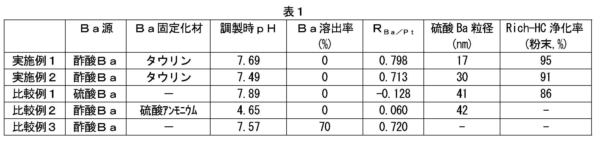
表1および図3~6の結果より、比較例1および2では、Baが担体二次粒子の外部に凝集しているのに対して、実施例1では担体二次粒子内部にBaが高度に分散して担持されていることがわかる。
相関係数の値が0.5以上では強い相関、0.7以上では特に強い相関があると解釈されるが、実施例1では、相関係数RBa/Ptの値が0.798であり、Ptの存在位置とBaの存在位置に特に強い相関があることが認められる。
一方、比較例1および比較例2では、相関係数RBa/Ptの値はそれぞれ-0.128、0.060であり、PtとBaの存在位置に相関関係は認められない。
このことから、比較例1および2に比べて実施例1では、Baが高度に分散しているだけでなく、PtとBaが近接していることがわかる。
比較例3では、相関係数RBa/Ptの値が0.720と、PtとBaの存在位置に強い相関が認められるが、Ba溶出率が70%であり、Baを固定化することができなかった。
相関係数の値が0.5以上では強い相関、0.7以上では特に強い相関があると解釈されるが、実施例1では、相関係数RBa/Ptの値が0.798であり、Ptの存在位置とBaの存在位置に特に強い相関があることが認められる。
一方、比較例1および比較例2では、相関係数RBa/Ptの値はそれぞれ-0.128、0.060であり、PtとBaの存在位置に相関関係は認められない。
このことから、比較例1および2に比べて実施例1では、Baが高度に分散しているだけでなく、PtとBaが近接していることがわかる。
比較例3では、相関係数RBa/Ptの値が0.720と、PtとBaの存在位置に強い相関が認められるが、Ba溶出率が70%であり、Baを固定化することができなかった。
<試験例4:Pt含有粉末材料のHC浄化率測定>
実施例1および比較例1で用いたPt含有粉末材料のペレットを作製し、管状炉を用いてRich/Lean耐久を行った。その後、ベスト測機社製活性評価装置(CATA5000)を用いて空燃比をLeanからRichに切り替えてから3分後のHC浄化率を測定した。結果を図7に示す。
実施例1および比較例1で用いたPt含有粉末材料のペレットを作製し、管状炉を用いてRich/Lean耐久を行った。その後、ベスト測機社製活性評価装置(CATA5000)を用いて空燃比をLeanからRichに切り替えてから3分後のHC浄化率を測定した。結果を図7に示す。
図7が示すように、実施例1で用いたPt含有粉末材料の方がはるかに高いHC浄化率を示した。
実施例1では、Baが担体二次粒子に高分散担持されており、PtとBaの存在位置に相関が認められるほどにPtとBaが近接化されている。このため、Ptに対するBaの電子供与によりHC被毒抑制が起こり、Rich雰囲気時のHC浄化性能が向上したものと考えられる。
実施例1では、Baが担体二次粒子に高分散担持されており、PtとBaの存在位置に相関が認められるほどにPtとBaが近接化されている。このため、Ptに対するBaの電子供与によりHC被毒抑制が起こり、Rich雰囲気時のHC浄化性能が向上したものと考えられる。
<試験例5:Rh含有触媒層のFE-EPMAによる評価>
実施例1で作製した排ガス浄化用触媒の上層触媒層と下層触媒層の積層部を切り出し、断面を研磨した。断面に市販のカーボンコーター(株式会社真空デバイス製品:VC-100W)を使用して導電性物質としての炭素を蒸着した。この断面について、上記のFE-EPMA装置(JXA-8530F)を用いて、面分析を行った。測定条件は、
ピクセルサイズ:0.85μm×0.85μm、
測定ピクセル数:256×256、
加速電圧:20kV、
照射電流:100nA、
プローブ径:当該測定条件における最小に設定、
単位測定時間:50ms/1ピクセル、
測定倍率:×400
とした。そして、ピクセル毎にBa元素の特性X線の強度(α:cps)およびRhの特性X線の強度(β:cps)を測定した。
なお、かかる面分析において、1ピクセル(区域)あたりのX線強度の閾値をBaでは15cps、Rhでは5cpsと設定し、閾値以下の強度を示したピクセルは、相関係数の算出のためのデータから除外した。
得られたデータを表計算ソフト「エクセル」のCORREL関数機能を用いて相関係数RBa/Rhを求めた。
その結果、相関係数RBa/Rhは、0.023であり、BaとRhの触媒中における存在位置に相関関係は認められなかった。このことから、実施例1の排ガス浄化用触媒では、Ptを含有するアルカリ土類金属担持領域である上層においてBaが固定化されていることにより、上層に存在するBaと下層に存在するRhとの接触を防止できていることがわかる。
実施例1で作製した排ガス浄化用触媒の上層触媒層と下層触媒層の積層部を切り出し、断面を研磨した。断面に市販のカーボンコーター(株式会社真空デバイス製品:VC-100W)を使用して導電性物質としての炭素を蒸着した。この断面について、上記のFE-EPMA装置(JXA-8530F)を用いて、面分析を行った。測定条件は、
ピクセルサイズ:0.85μm×0.85μm、
測定ピクセル数:256×256、
加速電圧:20kV、
照射電流:100nA、
プローブ径:当該測定条件における最小に設定、
単位測定時間:50ms/1ピクセル、
測定倍率:×400
とした。そして、ピクセル毎にBa元素の特性X線の強度(α:cps)およびRhの特性X線の強度(β:cps)を測定した。
なお、かかる面分析において、1ピクセル(区域)あたりのX線強度の閾値をBaでは15cps、Rhでは5cpsと設定し、閾値以下の強度を示したピクセルは、相関係数の算出のためのデータから除外した。
得られたデータを表計算ソフト「エクセル」のCORREL関数機能を用いて相関係数RBa/Rhを求めた。
その結果、相関係数RBa/Rhは、0.023であり、BaとRhの触媒中における存在位置に相関関係は認められなかった。このことから、実施例1の排ガス浄化用触媒では、Ptを含有するアルカリ土類金属担持領域である上層においてBaが固定化されていることにより、上層に存在するBaと下層に存在するRhとの接触を防止できていることがわかる。
<試験例6:排ガス浄化用触媒の浄化率測定>
実施例1および比較例1で作製した排ガス浄化用触媒をエンジンの排気系に設置し、エンジンを稼働させ耐久を行った。
かかる耐久試験後、その触媒を用いてエンジンに供給する混合ガスの空燃比をLeanからRichに切り替えてから3分後のHC浄化率およびNOx浄化率を測定した。結果を図8および図9に示す。
実施例1および比較例1で作製した排ガス浄化用触媒をエンジンの排気系に設置し、エンジンを稼働させ耐久を行った。
かかる耐久試験後、その触媒を用いてエンジンに供給する混合ガスの空燃比をLeanからRichに切り替えてから3分後のHC浄化率およびNOx浄化率を測定した。結果を図8および図9に示す。
図8および図9の結果が示すように、実施例1の排ガス浄化用触媒は、比較例1の排ガス浄化用触媒よりもはるかに高いHC浄化率およびNOx浄化率を示した。この理由は次のように考えられる。
実施例1では、Baが担体二次粒子に高分散担持されているため、PtとBaの存在位置に相関が認められるほどにPtとBaとが近接化されている。このため、Ptに対するBaの電子供与によりHC被毒抑制が起こり、Rich雰囲気時のHC浄化性能が向上する。さらにBaが固定化されていることにより、BaとRhとの接触が防止されており、これにより、BaによるRhのメタル化抑制が防止されている。さらに、上流のPt含有触媒層のHC浄化作用が向上することによって下流のRh含有触媒層へ流入するHC量が減少することにより、Rhの被毒が抑制される。以上のことから共存NOxの浄化性能も向上する。
実施例1では、Baが担体二次粒子に高分散担持されているため、PtとBaの存在位置に相関が認められるほどにPtとBaとが近接化されている。このため、Ptに対するBaの電子供与によりHC被毒抑制が起こり、Rich雰囲気時のHC浄化性能が向上する。さらにBaが固定化されていることにより、BaとRhとの接触が防止されており、これにより、BaによるRhのメタル化抑制が防止されている。さらに、上流のPt含有触媒層のHC浄化作用が向上することによって下流のRh含有触媒層へ流入するHC量が減少することにより、Rhの被毒が抑制される。以上のことから共存NOxの浄化性能も向上する。
以上、本発明の具体例を詳細に説明したが、これらは例示にすぎず、請求の範囲を限定するものではない。請求の範囲に記載の技術には、以上に例示した具体例を様々に変形、変更したものが含まれる。
Claims (8)
- 内燃機関の排気管に配置されて当該内燃機関から排出される排ガスの浄化を行う排ガス浄化用触媒であって、
基材と、
当該基材上に形成された触媒層と、
を備えており、
前記触媒層は、
無機化合物から構成される多孔質担体と、
前記多孔質担体に担持されたPtと、
前記多孔質担体に担持された、少なくとも一種のアルカリ土類金属の硫酸塩と、
を備えるアルカリ土類金属担持領域を有しており、
ここで、前記触媒層のアルカリ土類金属担持領域の断面について、
ピクセルサイズ 0.34μm×0.34μm;
測定ピクセル数 256×256;
の条件でFE-EPMAによる面分析を行い、前記アルカリ土類金属の元素(Ae)の特性X線の強度(α:cps)およびPtの特性X線の強度(β:cps)を各ピクセルについて測定し、得られた各ピクセルにおけるαおよびβを用いて算出したピアソンの相関係数をRAe/Ptとしたとき、
当該RAe/Ptの値が0.5以上であることを特徴とする、排ガス浄化用触媒。 - 前記相関係数RAe/Ptの値が0.7以上である、請求項1に記載の排ガス浄化用触媒。
- 前記多孔質担体に担持されたアルカリ土類金属硫酸塩のX線回折法に基づく平均粒径が、30nm以下である、請求項1または2に記載の排ガス浄化用触媒。
- 前記触媒層の排ガスが流れる方向の下流側に、Rhを触媒金属とする触媒層をさらに有する、請求項1~3のいずれか1項に記載の排ガス浄化用触媒。
- 前記アルカリ土類金属硫酸塩として少なくとも硫酸バリウム(BaSO4)を有している、請求項1~4のいずれか1項に記載の排ガス浄化用触媒。
- 内燃機関の排気管に配置されて当該内燃機関から排出される排ガスの浄化を行う排ガス浄化用触媒を製造する方法であって、
基材上に、
無機化合物から構成される多孔質担体と、
当該多孔質担体に担持されたPtと、
当該多孔質担体に担持された少なくとも一種のアルカリ土類金属の硫酸塩と、
を備えるアルカリ土類金属担持領域を少なくとも一部に有する触媒層を形成する工程、および
前記触媒層が形成された基材を焼成する工程、
を包含し、
ここで、前記触媒層の形成工程は、
以下の成分:
前記多孔質担体を構成する無機化合物粒子;
Pt粒子またはPtを析出させるための前駆物質;
前記アルカリ土類金属の水溶性化合物;および
構成元素としてSを含有し、前記アルカリ土類金属の硫酸塩を生成可能なS含有水溶性有機化合物;
を水系溶媒と混合し、原料懸濁物を調製すること、
前記原料懸濁物を乾燥し、さらに焼成することによって、前記多孔質担体とPtとアルカリ土類金属の硫酸塩とが混在する粉末材料を調製すること、
少なくとも前記粉末材料と水系溶媒を含むアルカリ土類金属担持領域形成用スラリーを調製すること、および
前記スラリーを用いて前記基材上に前記アルカリ土類金属担持領域を形成すること、
を包含する、排ガス浄化用触媒の製造方法。 - 前記S含有水溶性有機化合物として、スルホ基(-SO3H)、スルホニル基(-S(=O)2-)およびスルフィニル基(-S(=O)-)のうちの少なくとも一つの官能基を有する水溶性有機物が使用される、請求項6に記載の排ガス浄化用触媒の製造方法。
- 前記アルカリ土類金属の水溶性化合物として、Ba、SrおよびCaのうちから選択される何れかのアルカリ土類金属の酢酸塩、亜硝酸塩またはヨウ化物が使用される、請求項6または7に記載の排ガス浄化用触媒の製造方法。
Priority Applications (3)
| Application Number | Priority Date | Filing Date | Title |
|---|---|---|---|
| EP19868631.3A EP3854478B1 (en) | 2018-10-04 | 2019-09-09 | Exhaust gas purification catalyst |
| CN201980065477.9A CN112789107B (zh) | 2018-10-04 | 2019-09-09 | 排气净化用催化剂 |
| US17/276,505 US11821349B2 (en) | 2018-10-04 | 2019-09-09 | Exhaust gas purification catalyst |
Applications Claiming Priority (2)
| Application Number | Priority Date | Filing Date | Title |
|---|---|---|---|
| JP2018189365A JP6990161B2 (ja) | 2018-10-04 | 2018-10-04 | 排ガス浄化用触媒 |
| JP2018-189365 | 2018-10-04 |
Publications (1)
| Publication Number | Publication Date |
|---|---|
| WO2020071059A1 true WO2020071059A1 (ja) | 2020-04-09 |
Family
ID=70054933
Family Applications (1)
| Application Number | Title | Priority Date | Filing Date |
|---|---|---|---|
| PCT/JP2019/035399 Ceased WO2020071059A1 (ja) | 2018-10-04 | 2019-09-09 | 排ガス浄化用触媒 |
Country Status (5)
| Country | Link |
|---|---|
| US (1) | US11821349B2 (ja) |
| EP (1) | EP3854478B1 (ja) |
| JP (1) | JP6990161B2 (ja) |
| CN (1) | CN112789107B (ja) |
| WO (1) | WO2020071059A1 (ja) |
Cited By (1)
| Publication number | Priority date | Publication date | Assignee | Title |
|---|---|---|---|---|
| US11786885B2 (en) | 2021-08-13 | 2023-10-17 | Johnson Matthey Public Limited Company | Sulfur-containing organic compound assisted metal nanoparticle synthesis for three-way catalysis application |
Families Citing this family (2)
| Publication number | Priority date | Publication date | Assignee | Title |
|---|---|---|---|---|
| JP7317787B2 (ja) | 2020-10-19 | 2023-07-31 | トヨタ自動車株式会社 | 排ガス浄化装置 |
| US20240269612A1 (en) * | 2023-02-13 | 2024-08-15 | Johnson Matthey Public Limited Company | Sulfur-containing organic compound assisted metal nanoparticle synthesis for three-way catalysis application |
Citations (7)
| Publication number | Priority date | Publication date | Assignee | Title |
|---|---|---|---|---|
| JPH01285639A (ja) | 1988-05-09 | 1989-11-16 | Kokusan Denki Co Ltd | 内燃機関用速度制御装置 |
| JPH05237390A (ja) | 1992-02-28 | 1993-09-17 | Nippon Shokubai Co Ltd | 排気ガス浄化用触媒 |
| WO2010137658A1 (ja) * | 2009-05-27 | 2010-12-02 | 株式会社 キャタラー | 排ガス浄化用触媒及びその製造方法 |
| WO2010147163A1 (ja) * | 2009-06-16 | 2010-12-23 | 株式会社 キャタラー | 排ガス浄化用触媒、粉末材料、及び排ガス浄化用触媒の製造方法 |
| WO2011030831A1 (ja) * | 2009-09-10 | 2011-03-17 | 株式会社 キャタラー | 排ガス浄化用触媒 |
| WO2018190300A1 (ja) * | 2017-04-11 | 2018-10-18 | 株式会社キャタラー | 排ガス浄化用触媒 |
| JP2018189365A (ja) | 2017-04-28 | 2018-11-29 | 日立ジョンソンコントロールズ空調株式会社 | 空気調和機 |
Family Cites Families (11)
| Publication number | Priority date | Publication date | Assignee | Title |
|---|---|---|---|---|
| US3932309A (en) | 1974-06-05 | 1976-01-13 | W. R. Grace & Co. | Auto exhaust catalysts prepared from sulfite treated platinum and palladium salt solutions |
| JP3812132B2 (ja) | 1998-04-03 | 2006-08-23 | 松下電器産業株式会社 | 排ガス浄化用触媒及びその製造方法 |
| DE19847008A1 (de) | 1998-10-13 | 2000-04-20 | Degussa | Stickoxid-Speicherkatalysator |
| JP2001232208A (ja) | 2000-02-25 | 2001-08-28 | Toyota Motor Corp | 排ガス浄化用触媒及びその製造方法 |
| JP4200768B2 (ja) | 2003-01-22 | 2008-12-24 | マツダ株式会社 | 排気ガス浄化用三元触媒 |
| JP5322526B2 (ja) | 2008-07-17 | 2013-10-23 | エヌ・イーケムキャット株式会社 | 自動車から排出される排気ガスを浄化するためのハニカム構造型触媒及びその製造方法、並びに、その触媒を使用した排気ガス浄化方法 |
| JP5337875B2 (ja) * | 2009-05-27 | 2013-11-06 | 株式会社キャタラー | 排ガス浄化用触媒 |
| JP2014161771A (ja) | 2013-02-22 | 2014-09-08 | Toyota Motor Corp | 排ガス浄化触媒の製造方法および排ガス浄化触媒 |
| JP6272303B2 (ja) * | 2013-03-28 | 2018-01-31 | エヌ・イーケムキャット株式会社 | 硫酸バリウムを含むアルミナ材料とその製造方法、それを用いた排気ガス浄化用触媒 |
| JP5994808B2 (ja) | 2014-03-05 | 2016-09-21 | トヨタ自動車株式会社 | 排ガス浄化用触媒及びその製造方法 |
| US10710023B2 (en) | 2016-03-01 | 2020-07-14 | Cataler Corporation | Exhaust gas purification catalyst |
-
2018
- 2018-10-04 JP JP2018189365A patent/JP6990161B2/ja active Active
-
2019
- 2019-09-09 EP EP19868631.3A patent/EP3854478B1/en active Active
- 2019-09-09 WO PCT/JP2019/035399 patent/WO2020071059A1/ja not_active Ceased
- 2019-09-09 US US17/276,505 patent/US11821349B2/en active Active
- 2019-09-09 CN CN201980065477.9A patent/CN112789107B/zh active Active
Patent Citations (7)
| Publication number | Priority date | Publication date | Assignee | Title |
|---|---|---|---|---|
| JPH01285639A (ja) | 1988-05-09 | 1989-11-16 | Kokusan Denki Co Ltd | 内燃機関用速度制御装置 |
| JPH05237390A (ja) | 1992-02-28 | 1993-09-17 | Nippon Shokubai Co Ltd | 排気ガス浄化用触媒 |
| WO2010137658A1 (ja) * | 2009-05-27 | 2010-12-02 | 株式会社 キャタラー | 排ガス浄化用触媒及びその製造方法 |
| WO2010147163A1 (ja) * | 2009-06-16 | 2010-12-23 | 株式会社 キャタラー | 排ガス浄化用触媒、粉末材料、及び排ガス浄化用触媒の製造方法 |
| WO2011030831A1 (ja) * | 2009-09-10 | 2011-03-17 | 株式会社 キャタラー | 排ガス浄化用触媒 |
| WO2018190300A1 (ja) * | 2017-04-11 | 2018-10-18 | 株式会社キャタラー | 排ガス浄化用触媒 |
| JP2018189365A (ja) | 2017-04-28 | 2018-11-29 | 日立ジョンソンコントロールズ空調株式会社 | 空気調和機 |
Non-Patent Citations (1)
| Title |
|---|
| See also references of EP3854478A4 |
Cited By (2)
| Publication number | Priority date | Publication date | Assignee | Title |
|---|---|---|---|---|
| US11786885B2 (en) | 2021-08-13 | 2023-10-17 | Johnson Matthey Public Limited Company | Sulfur-containing organic compound assisted metal nanoparticle synthesis for three-way catalysis application |
| US12551869B2 (en) | 2021-08-13 | 2026-02-17 | Johnson Matthey Public Limited Company | Sulfur-containing organic compound assisted metal nanoparticle synthesis for three-way catalysis application |
Also Published As
| Publication number | Publication date |
|---|---|
| JP6990161B2 (ja) | 2022-02-15 |
| JP2020054982A (ja) | 2020-04-09 |
| US11821349B2 (en) | 2023-11-21 |
| EP3854478A4 (en) | 2021-07-28 |
| EP3854478A1 (en) | 2021-07-28 |
| US20210277814A1 (en) | 2021-09-09 |
| EP3854478B1 (en) | 2024-10-23 |
| CN112789107A (zh) | 2021-05-11 |
| CN112789107B (zh) | 2025-02-21 |
Similar Documents
| Publication | Publication Date | Title |
|---|---|---|
| JP7062642B2 (ja) | 排ガス浄化用触媒 | |
| CN103458997B (zh) | 废气净化催化剂 | |
| JP3274688B2 (ja) | 分離した白金及びロジウム成分を含有する触媒組成物 | |
| JP4858463B2 (ja) | 排気ガス浄化用触媒およびその製造方法 | |
| KR101438953B1 (ko) | 저온에서의 NOx 흡장성능이 개선된 LNT촉매 | |
| WO2014034524A1 (ja) | 排ガス浄化触媒 | |
| KR20180125611A (ko) | 희박 압축 천연 가스 엔진용 산화 촉매 | |
| CN107427822A (zh) | 核‑壳载体、其制造方法、使用该核‑壳载体的排气净化催化剂、其制造方法和使用所述排气净化催化剂净化排气的方法 | |
| KR20150131017A (ko) | 분리된 워시코트를 갖는 촉매 물품 및 이의 제조 방법 | |
| JP6990161B2 (ja) | 排ガス浄化用触媒 | |
| CN113573797A (zh) | 用于汽油废气应用的新型pgm纳米粒子twc催化剂 | |
| JP2024517672A (ja) | 近接結合エンジン用途の白金含有三元触媒 | |
| JP2005000829A (ja) | 排ガス浄化用触媒とその製造方法 | |
| CN117098602B (zh) | 废气净化用催化剂组合物和废气净化用催化剂 | |
| CN116367919B (zh) | 包含铂-铑双金属组分的三元转化催化剂组合物 | |
| JP4779271B2 (ja) | 触媒 | |
| JP5589320B2 (ja) | 排気ガス浄化用触媒及びその製造方法 | |
| CN117120161B (en) | Catalyst composition for exhaust gas purification and catalyst for exhaust gas purification | |
| WO2024014409A1 (ja) | 排ガス浄化用触媒組成物、排ガス浄化用触媒及び排ガス浄化システム | |
| JP2005021878A (ja) | 排ガス浄化触媒及びその製造方法 | |
| JP2025159499A (ja) | メタン酸化触媒およびその製造方法 | |
| WO2024165833A1 (en) | Transition metal incorporated alumina for improved three way catalysts | |
| CN117120161A (zh) | 废气净化用催化剂组合物和废气净化用催化剂 | |
| JP2006223949A (ja) | 排ガス浄化用触媒及びその製造方法 |
Legal Events
| Date | Code | Title | Description |
|---|---|---|---|
| 121 | Ep: the epo has been informed by wipo that ep was designated in this application |
Ref document number: 19868631 Country of ref document: EP Kind code of ref document: A1 |
|
| NENP | Non-entry into the national phase |
Ref country code: DE |
|
| ENP | Entry into the national phase |
Ref document number: 2019868631 Country of ref document: EP Effective date: 20210422 |
|
| WWG | Wipo information: grant in national office |
Ref document number: 201980065477.9 Country of ref document: CN |