WO2020071200A1 - 情報処理装置、情報処理方法、およびプログラム - Google Patents
情報処理装置、情報処理方法、およびプログラムInfo
- Publication number
- WO2020071200A1 WO2020071200A1 PCT/JP2019/037515 JP2019037515W WO2020071200A1 WO 2020071200 A1 WO2020071200 A1 WO 2020071200A1 JP 2019037515 W JP2019037515 W JP 2019037515W WO 2020071200 A1 WO2020071200 A1 WO 2020071200A1
- Authority
- WO
- WIPO (PCT)
- Prior art keywords
- head
- user
- information processing
- control unit
- interface control
- Prior art date
- Legal status (The legal status is an assumption and is not a legal conclusion. Google has not performed a legal analysis and makes no representation as to the accuracy of the status listed.)
- Ceased
Links
Images





Classifications
-
- G—PHYSICS
- G06—COMPUTING OR CALCULATING; COUNTING
- G06F—ELECTRIC DIGITAL DATA PROCESSING
- G06F3/00—Input arrangements for transferring data to be processed into a form capable of being handled by the computer; Output arrangements for transferring data from processing unit to output unit, e.g. interface arrangements
- G06F3/01—Input arrangements or combined input and output arrangements for interaction between user and computer
- G06F3/048—Interaction techniques based on graphical user interfaces [GUI]
- G06F3/0487—Interaction techniques based on graphical user interfaces [GUI] using specific features provided by the input device, e.g. functions controlled by the rotation of a mouse with dual sensing arrangements, or of the nature of the input device, e.g. tap gestures based on pressure sensed by a digitiser
-
- G—PHYSICS
- G06—COMPUTING OR CALCULATING; COUNTING
- G06F—ELECTRIC DIGITAL DATA PROCESSING
- G06F3/00—Input arrangements for transferring data to be processed into a form capable of being handled by the computer; Output arrangements for transferring data from processing unit to output unit, e.g. interface arrangements
- G06F3/01—Input arrangements or combined input and output arrangements for interaction between user and computer
- G06F3/048—Interaction techniques based on graphical user interfaces [GUI]
- G06F3/0484—Interaction techniques based on graphical user interfaces [GUI] for the control of specific functions or operations, e.g. selecting or manipulating an object, an image or a displayed text element, setting a parameter value or selecting a range
-
- G—PHYSICS
- G06—COMPUTING OR CALCULATING; COUNTING
- G06F—ELECTRIC DIGITAL DATA PROCESSING
- G06F3/00—Input arrangements for transferring data to be processed into a form capable of being handled by the computer; Output arrangements for transferring data from processing unit to output unit, e.g. interface arrangements
- G06F3/16—Sound input; Sound output
-
- G—PHYSICS
- G06—COMPUTING OR CALCULATING; COUNTING
- G06F—ELECTRIC DIGITAL DATA PROCESSING
- G06F3/00—Input arrangements for transferring data to be processed into a form capable of being handled by the computer; Output arrangements for transferring data from processing unit to output unit, e.g. interface arrangements
- G06F3/16—Sound input; Sound output
- G06F3/167—Audio in a user interface, e.g. using voice commands for navigating, audio feedback
-
- G—PHYSICS
- G10—MUSICAL INSTRUMENTS; ACOUSTICS
- G10K—SOUND-PRODUCING DEVICES; METHODS OR DEVICES FOR PROTECTING AGAINST, OR FOR DAMPING, NOISE OR OTHER ACOUSTIC WAVES IN GENERAL; ACOUSTICS NOT OTHERWISE PROVIDED FOR
- G10K11/00—Methods or devices for transmitting, conducting or directing sound in general; Methods or devices for protecting against, or for damping, noise or other acoustic waves in general
- G10K11/18—Methods or devices for transmitting, conducting or directing sound
-
- H—ELECTRICITY
- H04—ELECTRIC COMMUNICATION TECHNIQUE
- H04R—LOUDSPEAKERS, MICROPHONES, GRAMOPHONE PICK-UPS OR LIKE ACOUSTIC ELECTROMECHANICAL TRANSDUCERS; ELECTRIC HEARING AIDS; PUBLIC ADDRESS SYSTEMS
- H04R29/00—Monitoring arrangements; Testing arrangements
-
- H—ELECTRICITY
- H04—ELECTRIC COMMUNICATION TECHNIQUE
- H04R—LOUDSPEAKERS, MICROPHONES, GRAMOPHONE PICK-UPS OR LIKE ACOUSTIC ELECTROMECHANICAL TRANSDUCERS; ELECTRIC HEARING AIDS; PUBLIC ADDRESS SYSTEMS
- H04R5/00—Stereophonic arrangements
-
- H—ELECTRICITY
- H04—ELECTRIC COMMUNICATION TECHNIQUE
- H04R—LOUDSPEAKERS, MICROPHONES, GRAMOPHONE PICK-UPS OR LIKE ACOUSTIC ELECTROMECHANICAL TRANSDUCERS; ELECTRIC HEARING AIDS; PUBLIC ADDRESS SYSTEMS
- H04R5/00—Stereophonic arrangements
- H04R5/027—Spatial or constructional arrangements of microphones, e.g. in dummy heads
-
- H—ELECTRICITY
- H04—ELECTRIC COMMUNICATION TECHNIQUE
- H04S—STEREOPHONIC SYSTEMS
- H04S7/00—Indicating arrangements; Control arrangements, e.g. balance control
- H04S7/30—Control circuits for electronic adaptation of the sound field
- H04S7/302—Electronic adaptation of stereophonic sound system to listener position or orientation
- H04S7/303—Tracking of listener position or orientation
- H04S7/304—For headphones
-
- H—ELECTRICITY
- H04—ELECTRIC COMMUNICATION TECHNIQUE
- H04S—STEREOPHONIC SYSTEMS
- H04S2420/00—Techniques used stereophonic systems covered by H04S but not provided for in its groups
- H04S2420/01—Enhancing the perception of the sound image or of the spatial distribution using head related transfer functions [HRTF's] or equivalents thereof, e.g. interaural time difference [ITD] or interaural level difference [ILD]
-
- H—ELECTRICITY
- H04—ELECTRIC COMMUNICATION TECHNIQUE
- H04S—STEREOPHONIC SYSTEMS
- H04S7/00—Indicating arrangements; Control arrangements, e.g. balance control
- H04S7/40—Visual indication of stereophonic sound image
Definitions
- the present disclosure relates to an information processing device, an information processing method, and a program.
- Patent Literature 1 discloses a technique for reducing the burden on a subject by reducing the measurement time of the head-related transfer function.
- Patent Literature 1 requires extensive measurement equipment, and it is difficult for a general user to easily measure his or her own head transfer characteristics.
- an interface control unit that controls a user interface related to measurement of a head transfer function of a user is provided, and the interface control unit includes a guide information for guiding a head direction of the user in a specified direction.
- An information processing device for controlling an output is provided.
- the processor includes controlling a user interface related to measurement of a user's head-related transfer function, and controlling the user interface includes changing a direction of the user's head in a designated direction.
- An information processing method is further provided, further comprising: controlling output of guide information to be guided.
- the computer further includes an interface control unit that controls a user interface related to measurement of a head transfer function of the user, wherein the interface control unit sets the direction of the head of the user in a designated direction.
- a program for controlling the output of guide information to be guided and functioning as an information processing device is provided.
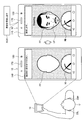
- FIG. 2 is a diagram illustrating an example of a user interface and guide information according to an embodiment of the present disclosure.
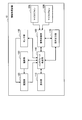
- FIG. 3 is a block diagram illustrating a functional configuration example of the information processing apparatus according to the embodiment.
- FIG. 3 is a diagram showing a specific example of interface control according to the embodiment.
- FIG. 3 is a diagram showing a specific example of interface control according to the embodiment.
- FIG. 3 is a diagram showing a specific example of interface control according to the embodiment.
- FIG. 3 is a diagram showing a specific example of interface control according to the embodiment.
- FIG. 14 is a diagram for describing individual optimization of a multi-channel head-related transfer function using the information processing apparatus according to the embodiment.
- FIG. 3 is a diagram illustrating an example of a user interface corresponding to a multi-channel measurement mode according to the embodiment. It is a flowchart which shows the flow of control by the interface control part concerning the embodiment.
- FIG. 2 is a diagram illustrating a hardware configuration example according to an embodiment of the present disclosure.
- FIG. 5 is a diagram for describing a general measurement of a head-related transfer function using a dummy head microphone.
- Embodiment 1.1 Overview 1.2. Functional configuration example of information processing apparatus 10 1.3. Specific example of control 1.4. 1. Flow of control 2. Hardware configuration example Conclusion
- Embodiment> ⁇ 1.1. Overview First, an outline of an embodiment of the present disclosure will be described. As described above, in recent years, attention has been focused on a head-related transfer function that mathematically represents a transfer characteristic of a sound from a sound source to both ears. According to the head-related transfer function, for example, it is possible to cause a sound output device such as headphones to express a sound image three-dimensionally.
- the head related transfer function is generally measured using a dummy head microphone.
- measurement of a general head-related transfer function using a dummy head microphone will be described.
- the speaker 30 and the dummy head microphone 40 are installed in the reference sound field RSF to be reproduced by the headphones 50.
- the measurement signal is reproduced from the speaker 30 and, as shown in the center of the figure, the head-related transfer functions of the left ear and the right ear are acquired by the microphones respectively provided at the binaural positions of the dummy head microphone 40.
- a process of convolving the head-related transfer functions of the left ear and the right ear with respect to the audio signal (source signal) to be reproduced is performed, and the signals for the left ear and the right ear are converted. Generate.
- the headphones 50 By causing the headphones 50 to reproduce the signal generated as described above, a sound image can be three-dimensionally expressed.
- the information processing apparatus 10 includes an interface control unit 140 that controls a user interface related to measurement of a user's head-related transfer function. Further, one of the features is that the interface control unit 140 according to an embodiment of the present disclosure controls output of guide information for guiding the direction of the user's head in a specified direction.
- FIG. 1 is a diagram showing an example of a user interface and guide information according to the present embodiment.
- FIG. 1 shows a control example of a user interface when the user U measures his or her head-related transfer function using the information processing apparatus 10 according to the present embodiment.
- FIG. 1 illustrates an example in which the information processing device 10 according to the present embodiment is a smartphone.
- the user U wears the microphones 20 ⁇ / b> L and 20 ⁇ / b> R on the left and right ears and operates the information processing device 10 to activate the user interface according to the present embodiment.
- a GUI Graphic User Interface
- the user interface according to the present embodiment may include a GUI.
- the interface control unit 140 outputs guide information for guiding the direction of the head of the user U in the designated direction.
- the specified direction may be a direction suitable for measuring the head-related transfer function.
- the above-mentioned designated direction uses the measurement signal related to the measurement of the head-related transfer function starting from the user U.
- the direction in which the audio output unit 170 to output may be located. That is, the designated direction according to the present embodiment can be set such that, for example, the user U and the audio output unit 170 face each other.
- the interface control unit 140 fixes the user's posture at the position of both ears suitable for the measurement of the head-related transfer function by guiding the direction of the head of the user U to the specified direction as described above. As a result, highly accurate measurement of the head-related transfer function can be realized.
- the guide information according to the present embodiment includes, for example, various types of visual information.
- the interface control unit 140 according to the present embodiment may cause the display unit 110 to display a guide object that guides the direction of the head of the user U in the specified direction.
- the interface control unit 140 may display the image of the user U captured by the capturing unit 120 on the display unit 110 in real time, and superimpose the guide object on the image.
- the interface control unit 140 transmits a frame object FF having a head shape according to the designated direction and a message that guides the user to align the position of the face captured by the frame object FF. Are displayed on the display unit 110 as guide information.
- the user U can easily adjust the position of the face UF to the frame object FF while checking his or her own image, and the user U is further conscious. It is possible to take a posture suitable for the measurement of the head-related transfer function without the need.
- the interface control unit 140 starts the measurement of the head-related transfer function based on the recognition unit 150 determining that the direction of the head of the user U substantially matches the specified direction.
- the output of the indicated start notification information may be controlled.
- the direction of the head of the user U substantially matches the specified direction. It may be determined that it has been done.
- the interface control unit 140 causes the audio output unit 170 to output a system utterance SO1 indicating the start of measurement, and displays a message indicating the start of measurement on the display unit 110. A case is shown.
- the user U can be guided to fix the head at the start of measurement, and a highly accurate head-related transfer function can be measured.
- the interface control unit 140 may control the start and interruption of the measurement process of the head related transfer function. For example, based on the recognition unit 150 determining that the direction of the head of the user U substantially matches the specified direction, the interface control unit 140 according to the present embodiment transmits the head to the signal processing unit 160 described below. The function measurement process may be started.
- the interface control unit 140 starts the measurement processing of the head-related transfer function by the signal processing unit 160 and then ends the measurement of the head of the user U until the measurement processing ends. If the recognizing unit 150 determines that the direction does not substantially match the designated direction, the signal processing unit 160 may interrupt the measurement process.
- the interface control unit 140 when the direction of the head of the user U deviates from the specified direction during the measurement, that is, the posture of the user U is suitable for the measurement of the head-related transfer function. If the posture does not exist, the accuracy of the acquired head-related transfer function can be maintained by causing the signal processing unit 160 to interrupt the measurement processing.
- the interface control unit 140 can also perform the above control based on the noise level around the user U. For example, when the noise level measured by the recognition unit 150 exceeds the threshold value, the interface control unit 140 according to the present embodiment may perform control so that the measurement processing of the head-related transfer function by the signal processing unit 160 is not started.
- the interface control unit 140 when the signal processing unit 160 starts the measurement processing of the head-related transfer function, and when it is detected that the noise level exceeds the threshold, the signal processing unit The measurement process may be interrupted at 160.
- the interface control unit 140 According to the above control by the interface control unit 140 according to the present embodiment, it is possible to prevent a low-precision head-related transfer function from being acquired in an environment with a high noise level.
- the interface control unit 140 may cause the display unit 110 to display noise information NI related to the noise level measured by the recognition unit 150, for example, as illustrated in FIG.
- the interface control unit 140 displays the noise information NI as a meter, and presents the user U with the current noise level and the noise level band (the hatched portion in the figure) for which measurement is permitted. .
- the user U is made to know whether or not the noise level in the surrounding environment is in a state suitable for the measurement of the head-related transfer function. For example, when the noise level is high, the noise level is reduced. It is possible to guide movement to a low place.
- the outline of the user interface controlled by the interface control unit 140 according to the embodiment has been described above. According to the above control by the interface control unit 140 according to the present embodiment, by guiding the user to a posture suitable for measurement, the user can easily and accurately measure his or her own head transfer characteristics. .
- the information processing apparatus 10 may be, for example, a mobile terminal such as a smartphone or a tablet.
- FIG. 2 is a block diagram illustrating a functional configuration example of the information processing apparatus 10 according to the present embodiment.
- the information processing apparatus 10 includes a display unit 110, an imaging unit 120, a sensor unit 130, an interface control unit 140, a recognition unit 150, a signal processing unit 160, and an audio output unit 170.
- a display unit 110 an imaging unit 120, a sensor unit 130, an interface control unit 140, a recognition unit 150, a signal processing unit 160, and an audio output unit 170.
- Display unit 110 The display unit 110 according to the present embodiment displays a GUI related to the measurement of the head-related transfer function based on the control by the interface control unit 140. To this end, the present embodiment is concerned.
- the display unit 110 includes a display device that presents visual information.
- the display device include a liquid crystal display (LCD), an organic light emitting diode (OLED) device, and a touch panel.
- LCD liquid crystal display
- OLED organic light emitting diode
- the image capturing unit 120 has a function of capturing an image of a user, for example.
- the photographing unit 120 according to the present embodiment includes a photographing device capable of photographing an image.
- the above-mentioned images include moving images in addition to still images.
- the sensor unit 130 has a function of collecting various sensor information related to the information processing device 10 and the surrounding environment.
- the sensor information collected by the sensor unit 130 is used for various recognition processes by the recognition unit 150.
- the sensor unit 130 according to the present embodiment includes, for example, a gyro sensor, an acceleration sensor, a geomagnetic sensor, a microphone, and the like.
- the interface control unit 140 has a function of controlling a user interface related to measurement of a head-related transfer function of a user. As described above, one of the features is that the interface control unit 140 according to the present embodiment controls output of guide information for guiding the direction of the user's head in the designated direction.
- the recognition unit 150 performs various types of recognition processing based on the image captured by the imaging unit 120 and the sensor information collected by the sensor unit 130. For example, the recognition unit 150 according to the present embodiment recognizes the orientation of the user's head. The recognition unit 150 may recognize the orientation of the head of the user based on the image captured by the capturing unit 120.
- the recognition unit 150 may determine that the orientation of the user's head is substantially one in the designated direction based on, for example, the fact that the user's face in the captured image is inside the frame object. It can also be determined that they do.
- the recognition unit 150 may recognize the orientation of the user's head based on the sensor information acquired from the microphone 20.
- the recognition unit 150 has a function of measuring a noise level in the surrounding environment based on sound information collected by the sensor unit.
- the signal processing unit 160 starts measurement processing of the head-related transfer function based on control by the interface control unit 140.
- the signal processing unit 160 according to the present embodiment may cause the audio output unit 170 to output a measurement signal based on a measurement start instruction input from the interface control unit 140.
- the signal processing unit 160 receives the head-related transfer functions acquired by the microphones 20L and 20R worn by the user, performs convolution processing based on the head-related transfer functions, and performs processing for the left and right ears. Generate an audio signal.
- the signal processing unit 160 according to the present embodiment can generate an audio signal using a known convolution technique.
- the signal processing unit 160 according to the present embodiment may use, for example, a technique disclosed in Japanese Patent Application Laid-Open No. 2014-060691 filed by the applicant of the present disclosure.
- the audio output unit 170 outputs audio based on control by the interface control unit 140 and the signal processing unit 160.
- the audio output unit 170 according to the present embodiment may output guide information and start notification information based on control by the interface control unit 140.
- the audio output unit 170 according to the present embodiment may output a measurement signal based on control by the signal processing unit 160.
- the example of the functional configuration of the information processing apparatus 10 according to the present embodiment has been described.
- the configuration described above with reference to FIG. 2 is merely an example, and the functional configuration of the information processing apparatus 10 according to the present embodiment is not limited to the example.
- the information processing apparatus 10 according to the present embodiment may be realized as a server, and control a mobile terminal including a display unit, a photographing unit, an audio output unit, and the like via a network.
- the information processing apparatus 10 according to the present embodiment may be realized as a microphone worn by a user on an ear, and control the mobile terminal via a network.
- the functional configuration of the information processing apparatus 10 according to the present embodiment can be flexibly modified according to specifications and operations.
- FIGS. 3 to 6 are diagrams showing specific examples of the interface control according to the present embodiment.
- FIG. 1 illustrates a case where the interface control unit 140 according to the present embodiment causes the display unit 110 to display a head-shaped frame object as guide information.
- the guide information according to the present embodiment Not limited.
- the guide object according to the present embodiment may be, for example, a wearable object mounted on the head.
- the interface control unit 140 causes the display unit 110 to display the glasses-shaped wearing object type object AO in addition to the head-shaped frame object FF.
- the interface control unit 140 determines that the recognition unit 150 determines that the face FF of the user U is inside the frame object FF and that the user's left eye LE and right eye RE
- the signal processing unit 160 may start the measurement process of the head-related transfer function based on the recognition that it is located at the assumed position in. According to the above control by the interface control unit 140 according to the present embodiment, it is possible to cause the user U to take a posture more suitable for measurement, and to measure a head transfer function with high accuracy.
- the wearing-type object AO is not limited to the eyeglasses shape as shown in FIG. 3 and may have various shapes such as a hat, headphones, and a headband.
- start notification information may be, for example, a light such as a jingle J, a flash light by the image capturing unit 120, a message, an image, a symbol, or the like, as shown in FIG.
- the user U may be able to start measuring the head-related transfer function by touching the measurement button displayed on the display unit 110.
- the designated direction according to the present embodiment is not necessarily limited to the direction in which the sound output unit 170 is located starting from the user's head.
- the designated direction according to the present embodiment may be appropriately set to measure the head-related transfer function at an arbitrary ear position.
- the interface control unit 140 causes the display unit 110 to display a frame object FF that guides the user U to turn his / her profile.
- the interface control unit 140 according to the present embodiment can also cause the display unit 110 to display the frame object FF having a head shape corresponding to the designated direction. According to the above function of the interface control unit 140 according to the present embodiment, it is possible to guide the direction of the user's head in various designated directions and measure head-related transfer functions corresponding to various ear positions. It becomes possible.
- the guide information according to the present embodiment may be audio information.
- the interface control unit 140 according to the present embodiment may cause the sound output unit 170 to output a sound for guiding the direction of the user's head in the specified direction.
- FIG. 5 illustrates an example in which the interface control unit 140 causes the signal processing unit 160 to start the measurement process of the head-related transfer function based on the recognition unit 150 recognizing the smile of the user U. .
- the recognition unit 150 according to the present embodiment can also recognize the direction of the user's head by the smile recognition.
- the interface control unit 140 may cause the audio output unit 170 to output a system utterance SO2 such as “Please look at the screen and laugh” as guide information.
- a system utterance SO2 such as “Please look at the screen and laugh” as guide information.
- the interface control unit 140 according to the present embodiment can effectively guide the direction of the user's head in the designated direction by outputting the guide information as visual information or audio information.
- the case where the user adjusts the direction of the head while the information processing apparatus 10 captures an image with the image capturing unit 120 (a so-called IN camera) provided on the surface of the display unit 110 has been described.
- the adjustment of the head orientation may be performed by a cooperator.
- the cooperator C adjusts the head orientation of the user U while photographing the user U using the photographing unit 120 (a so-called OUT camera) provided on the back side of the information processing device 10.
- the photographing unit 120 a so-called OUT camera
- the information processing apparatus 10 it is possible to cope with shooting by a cooperator or the like, and the user U cannot visually recognize the display unit 110 due to factors such as a designated direction. Also, the head-related transfer function can be measured with high accuracy.
- the interface control unit 140 outputs the measurement signal based on the position of the imaging unit 120 selected by the operator such as the user U or the cooperator C via the user interface.
- the output unit 170 may be selectable.
- the interface control unit 140 performs signal processing to output a measurement signal to the audio output unit 170 also arranged on the display unit 110 side.
- An instruction may be given to the unit 160.
- the interface control unit 140 transmits a voice signal also disposed on the back of the information processing device 10.
- the signal processing unit 160 may be instructed to output the measurement signal to the output unit 170.
- the interface control unit 140 by securing a path through which the measurement signal output from the audio output unit 170 is directly transmitted to the microphone 20 worn by the user U, It is possible to measure a head transfer function with high accuracy.
- the example of the interface control according to the present embodiment has been described above using a specific example.
- the interface control unit 140 according to the present embodiment may include a plurality of user interfaces corresponding to the head-related transfer function measurement mode, in addition to the user interfaces shown in FIGS. 1 and 3 to 6. In this case, the interface control unit 140 according to the present embodiment can control switching of the user interface based on the selected head-related transfer function measurement mode.
- the above measurement mode may be set according to the number of measurement channels, for example. That is, the interface control unit 140 according to the present embodiment can provide a user with a user interface corresponding to the number of measurement channels.
- FIG. 7 is a diagram for explaining personal optimization of a multi-channel head-related transfer function using the information processing apparatus 10 according to the present embodiment.
- the user U moves the information processing apparatus 10 to the five positions P1 to P5 corresponding to the five channels as shown on the left side of the drawing, and You are required to make head-related transfer function measurements at the location.
- the positions P1 to P5 may be relative positions based on the front of the head of the user U.
- the interface control unit 140 causes the display unit 110 to display a user interface for guiding the orientation of the user's head so that the head-related transfer functions can be accurately measured at the positions P1 to P5.
- a virtual sound field including five sound images SI1 to SI5 corresponding to the positions P1 to P1 is reproduced as shown on the right side of the drawing. It is possible to realize richer stereoscopic expression of sound.
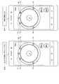
- FIG. 8 is a diagram illustrating an example of a user interface corresponding to the multi-channel measurement mode according to the present embodiment.
- the interface control unit 140 displays, for example, targets T1 to T5 corresponding to each channel and a marker M indicating the orientation of the user's head recognized by the recognition unit 150, as shown in the drawing. To display in real time.
- the interface control unit 140 outputs the system utterance SO3 as guide information. May guide the orientation of the user's head.
- the interface control unit 140 causes the user to output a system utterance SO4 as start notification information, and to perform measurement by the user.
- the start of the process is grasped, and guidance is made to maintain the posture.
- the interface control unit 140 according to the present embodiment may repeat the above control until the measurement processing is completed for all the targets T.
- the user can easily and accurately measure his or her own head transfer characteristics regardless of the number of channels.
- FIG. 9 is a flowchart illustrating a flow of control by the interface control unit 140 according to the present embodiment.
- the interface control unit 140 activates the user interface and the photographing unit 120 based on a user operation (S1101).
- the interface control unit 140 causes the display unit 110 and the audio output unit 170 to output guide information (S1102).
- the recognizing unit 150 determines whether or not the orientation of the user's head and the specified direction have been substantially matched (S1103).
- the recognizing unit 150 repeatedly executes the determination processing in step S1103 until determining that the orientation of the user's head substantially matches the specified direction.
- the recognizing unit 150 determines whether the noise level in the surrounding environment is equal to or less than a threshold (S1104).
- the recognition unit 150 may return to step S1103.
- the interface control unit 140 causes the signal processing unit 160 to start the head-related transfer function measurement process (S1105). .
- the recognizing unit 150 determines again whether or not the orientation of the user's head and the specified direction have been substantially matched (S1106).
- the interface control unit 140 when it is detected that the orientation of the user's head does not substantially match the designated direction, that is, that the orientation of the user's head deviates from the designated direction (S1106: NO), the interface control unit 140 Then, the signal processing unit 160 stops the measurement processing of the head related transfer function (S1109).
- the recognition unit 150 determines whether the noise level in the surrounding environment is equal to or lower than the threshold (S1107).
- the interface control unit 140 causes the signal processing unit 160 to stop measuring the head-related transfer function (S1109).
- the interface control unit 140 determines whether the measurement processing of the head-related transfer function has been completed (S1108).
- the information processing apparatus 10 returns to step S1106 and repeatedly executes the subsequent determination.
- FIG. 10 is a block diagram illustrating a hardware configuration example of the information processing device 10 according to an embodiment of the present disclosure.
- the information processing apparatus 10 includes a processor 871, a ROM 872, a RAM 873, a host bus 874, a bridge 875, an external bus 876, an interface 877, an input device 878, and an output device 879.
- a storage 880, a drive 881, a connection port 882, and a communication device 883 Note that the hardware configuration shown here is an example, and some of the components may be omitted. Further, components other than the components shown here may be further included.
- the processor 871 functions as, for example, an arithmetic processing device or a control device, and controls the entire operation of each component or a part thereof based on various programs recorded in the ROM 872, the RAM 873, the storage 880, or the removable recording medium 901. .
- the ROM 872 is a means for storing a program read by the processor 871, data used for calculation, and the like.
- the RAM 873 temporarily or permanently stores, for example, a program read by the processor 871 and various parameters that appropriately change when the program is executed.
- the processor 871, the ROM 872, and the RAM 873 are mutually connected, for example, via a host bus 874 capable of high-speed data transmission.
- the host bus 874 is connected to, for example, an external bus 876 having a relatively low data transmission speed via a bridge 875.
- the external bus 876 is connected to various components via an interface 877.
- Input device 8708 As the input device 878, for example, a mouse, a keyboard, a touch panel, a button, a switch, a lever, and the like are used. Further, as the input device 878, a remote controller (hereinafter, remote controller) capable of transmitting a control signal using infrared rays or other radio waves may be used. Further, the input device 878 includes a voice input device such as a microphone.
- the output device 879 transmits acquired information to a user, such as a display device such as a CRT (Cathode Ray Tube), an LCD or an organic EL, an audio output device such as a speaker or a headphone, a printer, a mobile phone, or a facsimile. It is a device that can visually or audibly notify the user.
- the output device 879 according to the present disclosure includes various vibration devices capable of outputting a tactile stimulus.
- the storage 880 is a device for storing various data.
- a magnetic storage device such as a hard disk drive (HDD), a semiconductor storage device, an optical storage device, a magneto-optical storage device, or the like is used.
- the drive 881 is a device that reads information recorded on a removable recording medium 901 such as a magnetic disk, an optical disk, a magneto-optical disk, or a semiconductor memory, or writes information on the removable recording medium 901.
- a removable recording medium 901 such as a magnetic disk, an optical disk, a magneto-optical disk, or a semiconductor memory
- the removable recording medium 901 is, for example, a DVD medium, a Blu-ray (registered trademark) medium, an HD DVD medium, various semiconductor storage media, and the like.
- the removable recording medium 901 may be, for example, an IC card on which a non-contact type IC chip is mounted, or an electronic device.
- connection port 882 is, for example, a port for connecting an external connection device 902 such as a USB (Universal Serial Bus) port, an IEEE1394 port, a SCSI (Small Computer System Interface), an RS-232C port, or an optical audio terminal. is there.
- an external connection device 902 such as a USB (Universal Serial Bus) port, an IEEE1394 port, a SCSI (Small Computer System Interface), an RS-232C port, or an optical audio terminal. is there.
- the external connection device 902 is, for example, a printer, a portable music player, a digital camera, a digital video camera, or an IC recorder.
- the communication device 883 is a communication device for connecting to a network.
- the information processing device 10 includes the interface control unit 140 that controls the user interface related to the measurement of the head transfer function of the user. Further, one of the features is that the interface control unit 140 according to an embodiment of the present disclosure controls output of guide information for guiding the direction of the user's head in a specified direction. According to such a configuration, it becomes possible for the user to measure his or her own head transfer characteristics with high accuracy.
- a program for causing a hardware such as a CPU, a ROM, and a RAM built in the computer to exhibit the same function as the configuration of the information processing apparatus 10 can be created.
- Possible non-transitory recording media can also be provided.
- each step related to the processing of the information processing device 10 in this specification does not necessarily need to be processed in a time series in the order described in the flowchart.
- each step related to the processing of the information processing device 10 may be processed in an order different from the order described in the flowchart, or may be processed in parallel.
- An interface control unit that controls a user interface related to measurement of a head-related transfer function of the user, With The interface control unit controls output of guide information for guiding the direction of the user's head in a designated direction, Information processing device.
- the guide information includes visual information
- the interface control unit causes a display unit to display a guide object that guides the direction of the user's head in the designated direction, The information processing device according to (1).
- the guide object includes a frame object having a head shape corresponding to the designated direction.
- the information processing device includes a wearable object mounted on a head.
- the guide information includes audio information
- the interface control unit causes a sound output unit to output a sound for guiding the direction of the user's head in the designated direction,
- the information processing apparatus according to any one of (1) to (5).
- the designated direction includes a direction in which an audio output unit that outputs a measurement signal relating to the measurement of the head related transfer function is located starting from the head of the user.
- the interface control unit controls the output of start notification information indicating the start of the measurement of the head-related transfer function, based on the determination that the orientation of the user's head substantially matches the specified direction,
- the information processing apparatus according to any one of (1) to (5).
- the information processing device according to any one of (1) to (8), wherein the interface control unit controls switching of the user interface based on a measurement mode of the head-related transfer function.
- the information processing device according to (9), wherein the measurement mode is set according to the number of measurement channels.
- Information processing device is configured to a mobile terminal including an audio output unit that outputs a measurement signal related to the measurement of the head-related transfer function.
- the mobile terminal includes at least two photographing units and at least two audio output units, The interface control unit, based on the position of the imaging unit selected by the operator via the user interface, to select the audio output unit to output the measurement signal, The information processing device according to (11). (13) (1) to (12), wherein the interface control unit starts the measurement processing of the head-related transfer function based on the determination that the orientation of the head of the user substantially matches the specified direction. An information processing device according to any one of the above. (14) The interface control unit is configured to determine that the direction of the head of the user does not substantially match the designated direction after the measurement process of the head-related transfer function is started and before the measurement process is completed. The information processing apparatus according to (13), wherein the measurement processing is interrupted based on the fact.
- a processor controlling a user interface for measuring a user's head related transfer function Controlling the user interface further includes controlling output of guide information for guiding the orientation of the user's head in a specified direction, Information processing method.
- Computer An interface control unit that controls a user interface related to measurement of a head transfer function of a user, The interface control unit controls output of guide information for guiding the direction of the user's head in a designated direction, A program for functioning as an information processing device.
- Reference Signs List 10 information processing device 110 display unit 120 imaging unit 130 sensor unit 140 interface control unit 150 recognition unit 160 signal processing unit 170 audio output unit 20 microphone
Landscapes
- Engineering & Computer Science (AREA)
- Theoretical Computer Science (AREA)
- General Engineering & Computer Science (AREA)
- Physics & Mathematics (AREA)
- Human Computer Interaction (AREA)
- General Physics & Mathematics (AREA)
- Acoustics & Sound (AREA)
- Signal Processing (AREA)
- Health & Medical Sciences (AREA)
- General Health & Medical Sciences (AREA)
- Audiology, Speech & Language Pathology (AREA)
- Multimedia (AREA)
- Otolaryngology (AREA)
- User Interface Of Digital Computer (AREA)
- Stereophonic System (AREA)
- Circuit For Audible Band Transducer (AREA)
Abstract
Description
1.実施形態
1.1.概要
1.2.情報処理装置10の機能構成例
1.3.制御の具体例
1.4.制御の流れ
2.ハードウェア構成例
3.まとめ
<<1.1.概要>>
まず、本開示の一実施形態の概要について説明する。上述したように、近年、音源から両耳までの音の伝達特性を数学的に表す頭部伝達関数が注目されている。頭部伝達関数によれば、例えば、ヘッドフォンなどの音出力装置に音像を立体的に表現させることが可能となる。
次に、本実施形態に係る情報処理装置10の機能構成例について説明する。本実施形態に係る情報処理装置10は、例えば、スマートフォンやタブレットなどのモバイル端末であってもよい。
本実施形態に係る表示部110は、インタフェース制御部140による制御に基づいて、頭部伝達関数の測定に係るGUIを表示する。このために、本実施形態に係る。
本実施形態に係る撮影部120は、例えば、ユーザの画像などを撮影する機能を有する。このために、本実施形態に係る撮影部120は、画像を撮影することが可能な撮影装置を備える。なお、上記の画像には、静止画像のほか動画像が含まれる。
本実施形態に係るセンサ部130は、情報処理装置10や周囲環境に関する種々のセンサ情報を収集する機能を有する。センサ部130が収集したセンサ情報は、認識部150による各種の認識処理に用いられる。本実施形態に係るセンサ部130は、例えば、ジャイロセンサ、加速度センサ、地磁気センサ、マイクロフォンなどを備える。
本実施形態に係るインタフェース制御部140は、ユーザの頭部伝達関数の測定に係るユーザインタフェースを制御する機能を有する。上述したように、本実施形態に係るインタフェース制御部140は、ユーザの頭部の向きを指定方向に誘導するガイド情報の出力を制御すること、を特徴の一つとする。
本実施形態に係る認識部150は、撮影部120が撮影した画像やセンサ部130が収集したセンサ情報に基づいて、各種の認識処理を行う。例えば、本実施形態に係る認識部150は、ユーザの頭部の向きを認識する。認識部150は、撮影部120が撮影した画像に基づいてユーザの頭部の向きを認識してもよい。
本実施形態に係る信号処理部160は、インタフェース制御部140による制御に基づいて頭部伝達関数の測定処理を開始する。例えば、本実施形態に係る信号処理部160は、インタフェース制御部140から入力された測定開始指示に基づいて、音声出力部170に測定用信号を出力させてもよい。
本実施形態に係る音声出力部170は、インタフェース制御部140や信号処理部160による制御に基づいて音声を出力する。例えば、本実施形態に係る音声出力部170は、インタフェース制御部140による制御に基づいて、ガイド情報や開始通知情報を出力してよい。また、例えば、本実施形態に係る音声出力部170は、信号処理部160による制御に基づいて測定用信号を出力してよい。
次に、本実施形態に係るインタフェース制御部140による制御について、図3~6を参照して、具体例を挙げながらより詳細に説明する。図3~図6は、本実施形態に係るインタフェース制御の具体例を示す図である。
次に、本実施形態に係るインタフェース制御部140による制御の流れについて詳細に説明する。図9は、本実施形態に係るインタフェース制御部140による制御の流れを示すフローチャートである。
次に、本開示の一実施形態に係る情報処理装置10のハードウェア構成例について説明する。図10は、本開示の一実施形態に係る情報処理装置10のハードウェア構成例を示すブロック図である。図10を参照すると、情報処理装置10は、例えば、プロセッサ871と、ROM872と、RAM873と、ホストバス874と、ブリッジ875と、外部バス876と、インタフェース877と、入力装置878と、出力装置879と、ストレージ880と、ドライブ881と、接続ポート882と、通信装置883と、を有する。なお、ここで示すハードウェア構成は一例であり、構成要素の一部が省略されてもよい。また、ここで示される構成要素以外の構成要素をさらに含んでもよい。
プロセッサ871は、例えば、演算処理装置又は制御装置として機能し、ROM872、RAM873、ストレージ880、又はリムーバブル記録媒体901に記録された各種プログラムに基づいて各構成要素の動作全般又はその一部を制御する。
ROM872は、プロセッサ871に読み込まれるプログラムや演算に用いるデータ等を格納する手段である。RAM873には、例えば、プロセッサ871に読み込まれるプログラムや、そのプログラムを実行する際に適宜変化する各種パラメータ等が一時的又は永続的に格納される。
プロセッサ871、ROM872、RAM873は、例えば、高速なデータ伝送が可能なホストバス874を介して相互に接続される。一方、ホストバス874は、例えば、ブリッジ875を介して比較的データ伝送速度が低速な外部バス876に接続される。また、外部バス876は、インタフェース877を介して種々の構成要素と接続される。
入力装置878には、例えば、マウス、キーボード、タッチパネル、ボタン、スイッチ、及びレバー等が用いられる。さらに、入力装置878としては、赤外線やその他の電波を利用して制御信号を送信することが可能なリモートコントローラ(以下、リモコン)が用いられることもある。また、入力装置878には、マイクロフォンなどの音声入力装置が含まれる。
出力装置879は、例えば、CRT(Cathode Ray Tube)、LCD、又は有機EL等のディスプレイ装置、スピーカ、ヘッドフォン等のオーディオ出力装置、プリンタ、携帯電話、又はファクシミリ等、取得した情報を利用者に対して視覚的又は聴覚的に通知することが可能な装置である。また、本開示に係る出力装置879は、触覚刺激を出力することが可能な種々の振動デバイスを含む。
ストレージ880は、各種のデータを格納するための装置である。ストレージ880としては、例えば、ハードディスクドライブ(HDD)等の磁気記憶デバイス、半導体記憶デバイス、光記憶デバイス、又は光磁気記憶デバイス等が用いられる。
ドライブ881は、例えば、磁気ディスク、光ディスク、光磁気ディスク、又は半導体メモリ等のリムーバブル記録媒体901に記録された情報を読み出し、又はリムーバブル記録媒体901に情報を書き込む装置である。
リムーバブル記録媒体901は、例えば、DVDメディア、Blu-ray(登録商標)メディア、HD DVDメディア、各種の半導体記憶メディア等である。もちろん、リムーバブル記録媒体901は、例えば、非接触型ICチップを搭載したICカード、又は電子機器等であってもよい。
接続ポート882は、例えば、USB(Universal Serial Bus)ポート、IEEE1394ポート、SCSI(Small Computer System Interface)、RS-232Cポート、又は光オーディオ端子等のような外部接続機器902を接続するためのポートである。
外部接続機器902は、例えば、プリンタ、携帯音楽プレーヤ、デジタルカメラ、デジタルビデオカメラ、又はICレコーダ等である。
通信装置883は、ネットワークに接続するための通信デバイスであり、例えば、有線又は無線LAN、Bluetooth(登録商標)、又はWUSB(Wireless USB)用の通信カード、光通信用のルータ、ADSL(Asymmetric Digital Subscriber Line)用のルータ、又は各種通信用のモデム等である。
以上説明したように、本開示の一実施形態に係る情報処理装置10は、ユーザの頭部伝達関数の測定に係るユーザインタフェースを制御するインタフェース制御部140を備える。また、本開示の一実施形態に係るインタフェース制御部140は、ユーザの頭部の向きを指定方向に誘導するガイド情報の出力を制御すること、を特徴の一つとする。係る構成によれば、ユーザが自身の頭部伝達特性を精度高く測定することを可能となる。
(1)
ユーザの頭部伝達関数の測定に係るユーザインタフェースを制御するインタフェース制御部、
を備え、
前記インタフェース制御部は、前記ユーザの頭部の向きを指定方向に誘導するガイド情報の出力を制御する、
情報処理装置。
(2)
前記ガイド情報は、視覚情報を含み、
前記インタフェース制御部は、前記ユーザの頭部の向きを前記指定方向に誘導するガイドオブジェクトを表示部に表示させる、
前記(1)に記載の情報処理装置。
(3)
前記インタフェース制御部は、撮影されたユーザの画像をリアルタイムに前記表示部に表示させ、前記ユーザの画像に前記ガイドオブジェクトを重畳させる、前記(2)に記載の情報処理装置。
(4)
前記ガイドオブジェクトは、前記指定方向に応じた頭部形状の枠オブジェクトを含む、前記(2)に記載の情報処理装置。
(5)
前記ガイドオブジェクトは、頭部に装着される装着品型オブジェクトを含む、前記(3)または(4)に記載の情報処理装置。
(6)
前記ガイド情報は、音声情報を含み、
前記インタフェース制御部は、前記ユーザの頭部の向きを前記指定方向に誘導する音声を音声出力部に出力させる、
前記(1)~(5)のいずれかに記載の情報処理装置。
(7)
前記指定方向は、前記ユーザの頭部を起点として前記頭部伝達関数の測定に係る測定用信号を出力する音声出力部が位置する方向を含む、前記(1)~(6)のいずれかに記載の情報処理装置。
(8)
前記インタフェース制御部は、前記ユーザの頭部の向きが前記指定方向に略一致したと判定されたことに基づいて、前記頭部伝達関数の測定の開始を示す開始通知情報の出力を制御する、前記(1)~(5)のいずれかに記載の情報処理装置。
(9)
前記インタフェース制御部は、前記頭部伝達関数の測定モードに基づいて、前記ユーザインタフェースの切り替えを制御する、前記(1)~(8)のいずれかに記載の情報処理装置。
(10)
前記測定モードは、測定チャンネル数に応じて設定される、前記(9)に記載の情報処理装置。
(11)
前記インタフェース制御部は、前記頭部伝達関数の測定に係る測定用信号を出力する音声出力部を備えるモバイル端末に前記ガイド情報を出力させる、前記(1)~(10)のいずれかに記載の情報処理装置。
(12)
前記モバイル端末は、少なくとも2つの撮影部と少なくとも2つの前記音声出力部とを備え、
前記インタフェース制御部は、操作者が前記ユーザインタフェースを介して選択した前記撮影部の位置に基づいて、前記測定用信号を出力させる前記音声出力部を選択する、
前記(11)に記載の情報処理装置。
(13)
前記インタフェース制御部は、前記ユーザの頭部の向きが前記指定方向に略一致したと判定されたことに基づいて、前記頭部伝達関数の測定処理を開始させる、前記(1)~(12)のいずれかに記載の情報処理装置。
(14)
前記インタフェース制御部は、前記頭部伝達関数の測定処理を開始させた後、前記測定処理が終了するまでの間に、前記ユーザの頭部の向きが前記指定方向と略一致しなくなったと判定されたことに基づいて、前記測定処理を中断させる、前記(13)に記載の情報処理装置。
(15)
前記インタフェース制御部は、測定されたノイズレベルが閾値を超える場合、前記測定処理が開始されないよう制御する、前記(13)または(14)に記載の情報処理装置。
(16)
前記インタフェース制御部は、前記頭部伝達関数の測定処理を開始させた後、前記ノイズレベルが閾値を超えたことが検出された場合、前記測定処理を中断させる、前記(15)に記載の情報処理装置。
(17)
前記インタフェース制御部は、測定された前記ノイズレベルに係るノイズ情報の出力を制御する、前記(15)または(16)に記載の情報処理装置。
(18)
前記ユーザの頭部の向きを認識する認識部、をさらに備える、前記(1)~(17)のいずれかに記載の情報処理装置。
(19)
プロセッサが、ユーザの頭部伝達関数の測定に係るユーザインタフェースを制御すること、を含み、
ユーザインタフェースを制御することは、前記ユーザの頭部の向きを指定方向に誘導するガイド情報の出力を制御すること、をさらに含む、
情報処理方法。
(20)
コンピュータを、
ユーザの頭部伝達関数の測定に係るユーザインタフェースを制御するインタフェース制御部、を備え、
前記インタフェース制御部は、前記ユーザの頭部の向きを指定方向に誘導するガイド情報の出力を制御する、
情報処理装置、として機能させるためのプログラム。
110 表示部
120 撮影部
130 センサ部
140 インタフェース制御部
150 認識部
160 信号処理部
170 音声出力部
20 マイクロフォン
Claims (20)
- ユーザの頭部伝達関数の測定に係るユーザインタフェースを制御するインタフェース制御部、
を備え、
前記インタフェース制御部は、前記ユーザの頭部の向きを指定方向に誘導するガイド情報の出力を制御する、
情報処理装置。 - 前記ガイド情報は、視覚情報を含み、
前記インタフェース制御部は、前記ユーザの頭部の向きを前記指定方向に誘導するガイドオブジェクトを表示部に表示させる、
請求項1に記載の情報処理装置。 - 前記インタフェース制御部は、撮影されたユーザの画像をリアルタイムに前記表示部に表示させ、前記ユーザの画像に前記ガイドオブジェクトを重畳させる、請求項2に記載の情報処理装置。
- 前記ガイドオブジェクトは、前記指定方向に応じた頭部形状の枠オブジェクトを含む、請求項2に記載の情報処理装置。
- 前記ガイドオブジェクトは、頭部に装着される装着品型オブジェクトを含む、請求項3に記載の情報処理装置。
- 前記ガイド情報は、音声情報を含み、
前記インタフェース制御部は、前記ユーザの頭部の向きを前記指定方向に誘導する音声を音声出力部に出力させる、
請求項1に記載の情報処理装置。 - 前記指定方向は、前記ユーザの頭部を起点として前記頭部伝達関数の測定に係る測定用信号を出力する音声出力部が位置する方向を含む、請求項1に記載の情報処理装置。
- 前記インタフェース制御部は、前記ユーザの頭部の向きが前記指定方向に略一致したと判定されたことに基づいて、前記頭部伝達関数の測定の開始を示す開始通知情報の出力を制御する、請求項1に記載の情報処理装置。
- 前記インタフェース制御部は、前記頭部伝達関数の測定モードに基づいて、前記ユーザインタフェースの切り替えを制御する、請求項1に記載の情報処理装置。
- 前記測定モードは、測定チャンネル数に応じて設定される、請求項9に記載の情報処理装置。
- 前記インタフェース制御部は、前記頭部伝達関数の測定に係る測定用信号を出力する音声出力部を備えるモバイル端末に前記ガイド情報を出力させる、請求項1に記載の情報処理装置。
- 前記モバイル端末は、少なくとも2つの撮影部と少なくとも2つの前記音声出力部とを備え、
前記インタフェース制御部は、操作者が前記ユーザインタフェースを介して選択した前記撮影部の位置に基づいて、前記測定用信号を出力させる前記音声出力部を選択する、
請求項11に記載の情報処理装置。 - 前記インタフェース制御部は、前記ユーザの頭部の向きが前記指定方向に略一致したと判定されたことに基づいて、前記頭部伝達関数の測定処理を開始させる、請求項1に記載の情報処理装置。
- 前記インタフェース制御部は、前記頭部伝達関数の測定処理を開始させた後、前記測定処理が終了するまでの間に、前記ユーザの頭部の向きが前記指定方向と略一致しなくなったと判定されたことに基づいて、前記測定処理を中断させる、請求項13に記載の情報処理装置。
- 前記インタフェース制御部は、測定されたノイズレベルが閾値を超える場合、前記測定処理が開始されないよう制御する、請求項13に記載の情報処理装置。
- 前記インタフェース制御部は、前記頭部伝達関数の測定処理を開始させた後、前記ノイズレベルが閾値を超えたことが検出された場合、前記測定処理を中断させる、請求項15に記載の情報処理装置。
- 前記インタフェース制御部は、測定された前記ノイズレベルに係るノイズ情報の出力を制御する、請求項15に記載の情報処理装置。
- 前記ユーザの頭部の向きを認識する認識部、をさらに備える、請求項1に記載の情報処理装置。
- プロセッサが、ユーザの頭部伝達関数の測定に係るユーザインタフェースを制御すること、を含み、
ユーザインタフェースを制御することは、前記ユーザの頭部の向きを指定方向に誘導するガイド情報の出力を制御すること、をさらに含む、
情報処理方法。 - コンピュータを、
ユーザの頭部伝達関数の測定に係るユーザインタフェースを制御するインタフェース制御部、を備え、
前記インタフェース制御部は、前記ユーザの頭部の向きを指定方向に誘導するガイド情報の出力を制御する、
情報処理装置、として機能させるためのプログラム。
Priority Applications (7)
| Application Number | Priority Date | Filing Date | Title |
|---|---|---|---|
| CN201980063871.9A CN112789586A (zh) | 2018-10-03 | 2019-09-25 | 信息处理设备、信息处理方法和程序 |
| EP19869013.3A EP3862860A4 (en) | 2018-10-03 | 2019-09-25 | INFORMATION PROCESSING DEVICE, INFORMATION PROCESSING PROCESS AND PROGRAM |
| US17/278,551 US11775164B2 (en) | 2018-10-03 | 2019-09-25 | Information processing device, information processing method, and program |
| KR1020217006946A KR102759677B1 (ko) | 2018-10-03 | 2019-09-25 | 정보 처리 장치, 정보 처리 방법 및 프로그램 |
| JP2020550329A JP7487663B2 (ja) | 2018-10-03 | 2019-09-25 | 情報処理装置、情報処理方法、およびプログラム |
| US18/462,111 US12164762B2 (en) | 2018-10-03 | 2023-09-06 | Information processing device, information processing method, and program |
| JP2024076575A JP7845402B2 (ja) | 2018-10-03 | 2024-05-09 | 情報処理方法、情報処理装置、およびプログラム |
Applications Claiming Priority (2)
| Application Number | Priority Date | Filing Date | Title |
|---|---|---|---|
| JP2018-188473 | 2018-10-03 | ||
| JP2018188473 | 2018-10-03 |
Related Child Applications (2)
| Application Number | Title | Priority Date | Filing Date |
|---|---|---|---|
| US17/278,551 A-371-Of-International US11775164B2 (en) | 2018-10-03 | 2019-09-25 | Information processing device, information processing method, and program |
| US18/462,111 Continuation US12164762B2 (en) | 2018-10-03 | 2023-09-06 | Information processing device, information processing method, and program |
Publications (1)
| Publication Number | Publication Date |
|---|---|
| WO2020071200A1 true WO2020071200A1 (ja) | 2020-04-09 |
Family
ID=70054520
Family Applications (1)
| Application Number | Title | Priority Date | Filing Date |
|---|---|---|---|
| PCT/JP2019/037515 Ceased WO2020071200A1 (ja) | 2018-10-03 | 2019-09-25 | 情報処理装置、情報処理方法、およびプログラム |
Country Status (6)
| Country | Link |
|---|---|
| US (2) | US11775164B2 (ja) |
| EP (1) | EP3862860A4 (ja) |
| JP (2) | JP7487663B2 (ja) |
| KR (1) | KR102759677B1 (ja) |
| CN (1) | CN112789586A (ja) |
| WO (1) | WO2020071200A1 (ja) |
Cited By (1)
| Publication number | Priority date | Publication date | Assignee | Title |
|---|---|---|---|---|
| WO2022059364A1 (ja) * | 2020-09-17 | 2022-03-24 | 日本電気株式会社 | 音響処理システム、音響処理方法、および記録媒体 |
Families Citing this family (3)
| Publication number | Priority date | Publication date | Assignee | Title |
|---|---|---|---|---|
| KR102759677B1 (ko) * | 2018-10-03 | 2025-02-03 | 소니그룹주식회사 | 정보 처리 장치, 정보 처리 방법 및 프로그램 |
| KR20210068409A (ko) | 2018-10-10 | 2021-06-09 | 소니그룹주식회사 | 정보 처리 장치, 정보 처리 방법 및 정보 처리 프로그램 |
| USD1061551S1 (en) * | 2022-05-26 | 2025-02-11 | Lg Electronics Inc. | Display panel or portion thereof with animated graphical user interface |
Citations (5)
| Publication number | Priority date | Publication date | Assignee | Title |
|---|---|---|---|---|
| JP2007251248A (ja) | 2006-03-13 | 2007-09-27 | Yamaha Corp | 頭部伝達関数測定装置 |
| US20120183161A1 (en) * | 2010-09-03 | 2012-07-19 | Sony Ericsson Mobile Communications Ab | Determining individualized head-related transfer functions |
| JP2014060691A (ja) | 2012-08-23 | 2014-04-03 | Sony Corp | 音声処理装置および方法、並びにプログラム |
| US20180091921A1 (en) * | 2016-09-27 | 2018-03-29 | Intel Corporation | Head-related transfer function measurement and application |
| WO2018110269A1 (ja) * | 2016-12-12 | 2018-06-21 | ソニー株式会社 | Hrtf測定方法、hrtf測定装置、およびプログラム |
Family Cites Families (18)
| Publication number | Priority date | Publication date | Assignee | Title |
|---|---|---|---|---|
| JP3868281B2 (ja) * | 2001-12-06 | 2007-01-17 | 日本精密測器株式会社 | 光電脈波式脈拍測定装置 |
| US20130007672A1 (en) * | 2011-06-28 | 2013-01-03 | Google Inc. | Methods and Systems for Correlating Head Movement with Items Displayed on a User Interface |
| CN102254164B (zh) * | 2011-08-04 | 2013-05-01 | 蔡翔 | 具有提示功能的人脸识别方法 |
| JP2015087695A (ja) * | 2013-11-01 | 2015-05-07 | セイコーエプソン株式会社 | 情報処理装置および情報処理装置の制御方法 |
| US9998654B2 (en) * | 2013-07-22 | 2018-06-12 | Panasonic Intellectual Property Corporation Of America | Information processing device and method for controlling information processing device |
| WO2015062649A1 (en) * | 2013-10-30 | 2015-05-07 | Huawei Technologies Co., Ltd. | Method and mobile device for processing an audio signal |
| US20150306330A1 (en) * | 2014-04-29 | 2015-10-29 | MaskSelect, Inc. | Mask Selection System |
| US9854371B2 (en) | 2014-10-22 | 2017-12-26 | Small Signals, Llc | Information processing system, apparatus and method for measuring a head-related transfer function |
| US20170332965A1 (en) * | 2014-11-25 | 2017-11-23 | Hitachi High-Technologies Corporation | Measurement system, head-mounted device, non-transitory computer readable medium, and service providing method |
| JP6324939B2 (ja) * | 2015-11-05 | 2018-05-16 | 株式会社ソニー・インタラクティブエンタテインメント | 情報処理装置およびログイン制御方法 |
| WO2017098775A1 (ja) * | 2015-12-11 | 2017-06-15 | ソニー株式会社 | 情報処理装置、情報処理方法およびプログラム |
| US10805757B2 (en) * | 2015-12-31 | 2020-10-13 | Creative Technology Ltd | Method for generating a customized/personalized head related transfer function |
| US9591427B1 (en) * | 2016-02-20 | 2017-03-07 | Philip Scott Lyren | Capturing audio impulse responses of a person with a smartphone |
| US9800990B1 (en) * | 2016-06-10 | 2017-10-24 | C Matter Limited | Selecting a location to localize binaural sound |
| CN206610308U (zh) * | 2017-01-05 | 2017-11-03 | 广州市晶密电子有限公司 | 一种通过眼睛定位引导来实现脸部识别的数据处理装置 |
| JP7135472B2 (ja) * | 2018-06-11 | 2022-09-13 | カシオ計算機株式会社 | 表示制御装置、表示制御方法及び表示制御プログラム |
| KR102759677B1 (ko) | 2018-10-03 | 2025-02-03 | 소니그룹주식회사 | 정보 처리 장치, 정보 처리 방법 및 프로그램 |
| KR20210068409A (ko) | 2018-10-10 | 2021-06-09 | 소니그룹주식회사 | 정보 처리 장치, 정보 처리 방법 및 정보 처리 프로그램 |
-
2019
- 2019-09-25 KR KR1020217006946A patent/KR102759677B1/ko active Active
- 2019-09-25 WO PCT/JP2019/037515 patent/WO2020071200A1/ja not_active Ceased
- 2019-09-25 US US17/278,551 patent/US11775164B2/en active Active
- 2019-09-25 CN CN201980063871.9A patent/CN112789586A/zh active Pending
- 2019-09-25 EP EP19869013.3A patent/EP3862860A4/en active Pending
- 2019-09-25 JP JP2020550329A patent/JP7487663B2/ja active Active
-
2023
- 2023-09-06 US US18/462,111 patent/US12164762B2/en active Active
-
2024
- 2024-05-09 JP JP2024076575A patent/JP7845402B2/ja active Active
Patent Citations (5)
| Publication number | Priority date | Publication date | Assignee | Title |
|---|---|---|---|---|
| JP2007251248A (ja) | 2006-03-13 | 2007-09-27 | Yamaha Corp | 頭部伝達関数測定装置 |
| US20120183161A1 (en) * | 2010-09-03 | 2012-07-19 | Sony Ericsson Mobile Communications Ab | Determining individualized head-related transfer functions |
| JP2014060691A (ja) | 2012-08-23 | 2014-04-03 | Sony Corp | 音声処理装置および方法、並びにプログラム |
| US20180091921A1 (en) * | 2016-09-27 | 2018-03-29 | Intel Corporation | Head-related transfer function measurement and application |
| WO2018110269A1 (ja) * | 2016-12-12 | 2018-06-21 | ソニー株式会社 | Hrtf測定方法、hrtf測定装置、およびプログラム |
Cited By (3)
| Publication number | Priority date | Publication date | Assignee | Title |
|---|---|---|---|---|
| WO2022059364A1 (ja) * | 2020-09-17 | 2022-03-24 | 日本電気株式会社 | 音響処理システム、音響処理方法、および記録媒体 |
| JPWO2022059364A1 (ja) * | 2020-09-17 | 2022-03-24 | ||
| JP7635786B2 (ja) | 2020-09-17 | 2025-02-26 | 日本電気株式会社 | 音響処理システム、音響処理方法、およびプログラム |
Also Published As
| Publication number | Publication date |
|---|---|
| US20230409185A1 (en) | 2023-12-21 |
| JP7487663B2 (ja) | 2024-05-21 |
| JP7845402B2 (ja) | 2026-04-14 |
| EP3862860A1 (en) | 2021-08-11 |
| JPWO2020071200A1 (ja) | 2021-09-24 |
| KR20210068402A (ko) | 2021-06-09 |
| KR102759677B1 (ko) | 2025-02-03 |
| CN112789586A (zh) | 2021-05-11 |
| US20220027033A1 (en) | 2022-01-27 |
| US12164762B2 (en) | 2024-12-10 |
| JP2024097913A (ja) | 2024-07-19 |
| EP3862860A4 (en) | 2021-11-17 |
| US11775164B2 (en) | 2023-10-03 |
Similar Documents
| Publication | Publication Date | Title |
|---|---|---|
| JP7845402B2 (ja) | 情報処理方法、情報処理装置、およびプログラム | |
| US12267591B2 (en) | Video processing method and related electronic device | |
| US9854371B2 (en) | Information processing system, apparatus and method for measuring a head-related transfer function | |
| RU2678481C2 (ru) | Устройство обработки информации, способ обработки информации и программа | |
| KR20190090069A (ko) | 웨어러블 디바이스의 상태에 기초하는 컴패니언 통신 디바이스 거동의 변경 | |
| CN104871069B (zh) | 眼镜设备和用于控制眼镜设备的方法、音频设备和用于提供音频信号的方法以及显示设备 | |
| CN105487657A (zh) | 声音响度的确定方法及装置 | |
| US10003905B1 (en) | Personalized end user head-related transfer function (HRTV) finite impulse response (FIR) filter | |
| JPWO2018110269A1 (ja) | Hrtf測定方法、hrtf測定装置、およびプログラム | |
| US12149915B2 (en) | Sound effect optimization method, electronic device, and storage medium | |
| WO2018000764A1 (zh) | 一种声道自动匹配的方法、装置以及耳机 | |
| CN107249166A (zh) | 一种完全沉浸式的耳机立体声实现方法及系统 | |
| JP2019040005A (ja) | 読み上げシステム及び読み上げ方法 | |
| CN114339582B (zh) | 双通道音频处理、方向感滤波器生成方法、装置以及介质 | |
| WO2023124972A1 (zh) | 显示状态切换方法、装置及系统、电子设备、存储介质 | |
| CN108574925A (zh) | 虚拟听觉环境中控制音频信号输出的方法和装置 | |
| WO2018116678A1 (ja) | 情報処理装置及びその制御方法 | |
| WO2023051750A1 (zh) | 一种数据处理方法以及相关设备 | |
| US12526566B2 (en) | Generating microphone arrays from user devices | |
| US12160714B2 (en) | Sound processing apparatus, sound processing system, sound processing method, and non-transitory computer readable medium storing program | |
| EP4446869A1 (en) | Visualization and customization of sound space | |
| JP6574295B1 (ja) | 情報処理システム、情報処理方法およびコンピュータプログラム | |
| JP2024010864A (ja) | 情報処理装置、情報処理プログラム、および、情報処理方法 | |
| CN109791429B (zh) | 头戴式显示设备及其输入控制方法 | |
| JP2016206960A (ja) | 音声映像入出力装置 |
Legal Events
| Date | Code | Title | Description |
|---|---|---|---|
| 121 | Ep: the epo has been informed by wipo that ep was designated in this application |
Ref document number: 19869013 Country of ref document: EP Kind code of ref document: A1 |
|
| ENP | Entry into the national phase |
Ref document number: 2020550329 Country of ref document: JP Kind code of ref document: A |
|
| NENP | Non-entry into the national phase |
Ref country code: DE |
|
| ENP | Entry into the national phase |
Ref document number: 2019869013 Country of ref document: EP Effective date: 20210503 |
|
| WWG | Wipo information: grant in national office |
Ref document number: 202117008473 Country of ref document: IN |