WO2020071352A1 - 配車計画システム、情報処理装置、及び配車計画システムの制御方法 - Google Patents
配車計画システム、情報処理装置、及び配車計画システムの制御方法Info
- Publication number
- WO2020071352A1 WO2020071352A1 PCT/JP2019/038718 JP2019038718W WO2020071352A1 WO 2020071352 A1 WO2020071352 A1 WO 2020071352A1 JP 2019038718 W JP2019038718 W JP 2019038718W WO 2020071352 A1 WO2020071352 A1 WO 2020071352A1
- Authority
- WO
- WIPO (PCT)
- Prior art keywords
- user
- utility
- vehicle allocation
- inquiry
- allocation planning
- Prior art date
- Legal status (The legal status is an assumption and is not a legal conclusion. Google has not performed a legal analysis and makes no representation as to the accuracy of the status listed.)
- Ceased
Links
Images


Classifications
-
- G—PHYSICS
- G06—COMPUTING OR CALCULATING; COUNTING
- G06Q—INFORMATION AND COMMUNICATION TECHNOLOGY [ICT] SPECIALLY ADAPTED FOR ADMINISTRATIVE, COMMERCIAL, FINANCIAL, MANAGERIAL OR SUPERVISORY PURPOSES; SYSTEMS OR METHODS SPECIALLY ADAPTED FOR ADMINISTRATIVE, COMMERCIAL, FINANCIAL, MANAGERIAL OR SUPERVISORY PURPOSES, NOT OTHERWISE PROVIDED FOR
- G06Q10/00—Administration; Management
- G06Q10/06—Resources, workflows, human or project management; Enterprise or organisation planning; Enterprise or organisation modelling
- G06Q10/063—Operations research, analysis or management
- G06Q10/0631—Resource planning, allocation, distributing or scheduling for enterprises or organisations
-
- G—PHYSICS
- G01—MEASURING; TESTING
- G01C—MEASURING DISTANCES, LEVELS OR BEARINGS; SURVEYING; NAVIGATION; GYROSCOPIC INSTRUMENTS; PHOTOGRAMMETRY OR VIDEOGRAMMETRY
- G01C21/00—Navigation; Navigational instruments not provided for in groups G01C1/00 - G01C19/00
- G01C21/26—Navigation; Navigational instruments not provided for in groups G01C1/00 - G01C19/00 specially adapted for navigation in a road network
- G01C21/34—Route searching; Route guidance
- G01C21/3407—Route searching; Route guidance specially adapted for specific applications
- G01C21/3438—Rendezvous; Ride sharing
-
- G—PHYSICS
- G01—MEASURING; TESTING
- G01C—MEASURING DISTANCES, LEVELS OR BEARINGS; SURVEYING; NAVIGATION; GYROSCOPIC INSTRUMENTS; PHOTOGRAMMETRY OR VIDEOGRAMMETRY
- G01C21/00—Navigation; Navigational instruments not provided for in groups G01C1/00 - G01C19/00
- G01C21/26—Navigation; Navigational instruments not provided for in groups G01C1/00 - G01C19/00 specially adapted for navigation in a road network
- G01C21/34—Route searching; Route guidance
- G01C21/3453—Special cost functions, i.e. other than distance or default speed limit of road segments
- G01C21/3484—Personalized, e.g. from learned user behaviour or user-defined profiles
-
- G—PHYSICS
- G01—MEASURING; TESTING
- G01C—MEASURING DISTANCES, LEVELS OR BEARINGS; SURVEYING; NAVIGATION; GYROSCOPIC INSTRUMENTS; PHOTOGRAMMETRY OR VIDEOGRAMMETRY
- G01C21/00—Navigation; Navigational instruments not provided for in groups G01C1/00 - G01C19/00
- G01C21/26—Navigation; Navigational instruments not provided for in groups G01C1/00 - G01C19/00 specially adapted for navigation in a road network
- G01C21/34—Route searching; Route guidance
- G01C21/3453—Special cost functions, i.e. other than distance or default speed limit of road segments
- G01C21/3492—Special cost functions, i.e. other than distance or default speed limit of road segments employing speed data or traffic data, e.g. real-time or historical
-
- G—PHYSICS
- G06—COMPUTING OR CALCULATING; COUNTING
- G06F—ELECTRIC DIGITAL DATA PROCESSING
- G06F18/00—Pattern recognition
- G06F18/20—Analysing
- G06F18/23—Clustering techniques
-
- G—PHYSICS
- G06—COMPUTING OR CALCULATING; COUNTING
- G06N—COMPUTING ARRANGEMENTS BASED ON SPECIFIC COMPUTATIONAL MODELS
- G06N20/00—Machine learning
-
- G—PHYSICS
- G06—COMPUTING OR CALCULATING; COUNTING
- G06Q—INFORMATION AND COMMUNICATION TECHNOLOGY [ICT] SPECIALLY ADAPTED FOR ADMINISTRATIVE, COMMERCIAL, FINANCIAL, MANAGERIAL OR SUPERVISORY PURPOSES; SYSTEMS OR METHODS SPECIALLY ADAPTED FOR ADMINISTRATIVE, COMMERCIAL, FINANCIAL, MANAGERIAL OR SUPERVISORY PURPOSES, NOT OTHERWISE PROVIDED FOR
- G06Q50/00—Information and communication technology [ICT] specially adapted for implementation of business processes of specific business sectors, e.g. utilities or tourism
- G06Q50/40—Business processes related to the transportation industry
-
- G—PHYSICS
- G08—SIGNALLING
- G08G—TRAFFIC CONTROL SYSTEMS
- G08G1/00—Traffic control systems for road vehicles
- G08G1/20—Monitoring the location of vehicles belonging to a group, e.g. fleet of vehicles, countable or determined number of vehicles
- G08G1/202—Dispatching vehicles on the basis of a location, e.g. taxi dispatching
Definitions
- the present invention relates to a vehicle allocation planning system, an information processing device, and a control method of a vehicle allocation planning system in transportation.
- Patent Literature 1 describes a demand traffic operation system configured to create a dispatch plan of a demand traffic vehicle that accepts a demand for more passengers while efficiently operating the demand traffic vehicle.
- the demand traffic operation system receives an itinerary request of a plurality of passengers including at least one of a desired departure time and a desired arrival time of a shared-ride type demand transportation vehicle and a departure place and a destination, and sets the itinerary request to a predetermined time.
- a dispatch plan for a demand transportation vehicle is created by distinguishing passengers on the condition that the desired arrival time or the desired departure time has been received before and within a specified period.
- Patent Document 2 describes a boarding intention determination device configured to efficiently transport a user to a destination while improving the convenience of a user using transportation.
- the boarding intention determination device obtains a positional relationship between boarding position information indicating a boarding point for boarding the moving object and user position information indicating the current location of the user, and the obtained positional relationship and the user's Based on the behavior information indicating the behavior, it is determined whether or not the user intends to get on the moving body, and assuming that the behavior information indicating the behavior of the user satisfies predetermined condition information, When the user browses the content related to the boarding point of, it is determined that the user intends to get on the moving object.
- Patent No. 63341352 Patent No. 6310606
- Patent Documents 1 and 2 information on the behavior of the user (user) such as the departure place, the destination, and the current location is transmitted to the system. 2. Description of the Related Art In recent years, due to an increase in awareness of personal information protection and privacy protection, restrictions on handling of personal information and privacy-related information have been stricter year by year. For this reason, it is expected that it will be difficult to realize a system on the premise that the information on the behavior of the user is collected on the business side as in Patent Documents 1 and 2.
- the present invention has been made in view of such a background, and has a vehicle allocation planning system, an information processing apparatus, and a vehicle allocation system capable of drafting a vehicle allocation plan according to a user's intention while considering handling of information on user behavior. It aims to provide a control method of a planning system.
- a vehicle dispatching planning system which is a vehicle dispatching planning device that is an information processing device that drafts a vehicle dispatching plan of a transportation means, and is communicably connected to the vehicle dispatching planning device,
- a user device that is an information processing device operated by a user of the transportation means, and the vehicle allocation planning device transmits to the user device an inquiry about travel demand that is information indicating an intention of the user for travel,
- An inquiry processing unit that receives an answer to the inquiry, a demand estimation unit that estimates the travel demand of the user based on the answer, and a dispatch plan unit that drafts the dispatch plan based on the estimated travel demand.
- the user device has sensor information that is information indicating the current or past state of the user device, and utility calculation for determining the utility of the user when moving.
- a storage unit that stores Dell, a utility calculation unit that applies the sensor information to the utility calculation model to determine the utility of the user, and the inquiry received from the vehicle allocation planning device, the answer based on the utility.
- a query responding unit that generates and sends the generated answer to the vehicle allocation planning device.
- FIG. 3 is a diagram illustrating main functions of the user device. It is a flowchart explaining a learning process. It is an example of a utility calculation model, sensor information, and simultaneous equations. It is a flowchart explaining an inquiry response process. It is an example of an inquiry history. It is a flowchart explaining a movement route presentation process. It is an example of a movement route presentation screen. It is a flowchart explaining a vehicle allocation planning process. It is a flowchart explaining a similarity calculation process. It is a flowchart explaining a clustering process.
- FIG. 1 shows a schematic configuration of a vehicle allocation planning system 1 shown as one embodiment.
- the vehicle allocation planning system 1 includes a vehicle allocation planning device 10 that makes a vehicle allocation plan for vehicles of transportation (route bus, shuttle bus, on-demand bus, taxi, shared motorcycle, etc.), and a communication network 5.
- the communication network 5 is a wireless or wired communication means such as the Internet, a mobile phone network, a LAN (Local Area Network), a WAN (Wide Area Network), or a dedicated line.
- the vehicle allocation planning device 10 is an information processing device (computer) managed by an administrator of an organization such as a transportation company, and is, for example, a personal computer, a server device, or a mainframe.
- the vehicle allocation planning device 10 transmits to the user device 20 a travel demand which is information indicating a user's intention (movement means to be selected and a travel route to be selected) relating to travel (movement from a departure place to a destination). And an answer to the above inquiry sent from the user device 20 is received.
- the vehicle allocation planning device 10 estimates the travel demand of the user based on the received answer, and drafts a vehicle allocation plan based on the estimated result. It should be noted that the response to the inquiry does not include information on the user's behavior (possible to correspond to personal information or privacy information).
- the user device 20 is an information processing device (computer) used by a user of a transportation facility, such as a smartphone, a tablet, a mobile phone, or a personal computer.
- the user device 20 provides the user with information and various services related to transportation.
- FIG. 2 shows an example of hardware constituting the vehicle allocation planning device 10 and the user device 20 (hereinafter, referred to as an information processing device 100).
- the information processing apparatus 100 includes a processor 101, a main storage device 102, an auxiliary storage device 103, an input device 104, an output device 105, and a communication device 106.
- the information processing device 100 constituting the user device 20 further includes a sensor device 107 in addition to the above configuration.
- the components of the information processing apparatus 100 are communicably connected to each other via communication means such as a bus (not shown).
- the information processing apparatus 100 may be configured such that all or a part of the configuration is realized by a virtual resource such as a cloud server of a cloud system.
- the processor 101 is configured using a CPU (Central Processing Unit), an MPU (Micro Processing Unit), or the like.
- CPU Central Processing Unit
- MPU Micro Processing Unit
- the processor 101 reads and executes a program stored in the main storage device 102, the functions of the vehicle allocation planning device 10 and the user device 20 are realized.
- the main storage device 102 is a device for storing programs and data, and is a ROM (Read Only Memory), a RAM (Random Access Memory), a nonvolatile semiconductor memory (NVRAM (Non Volatile RAM)), or the like.
- ROM Read Only Memory
- RAM Random Access Memory
- NVRAM Non Volatile RAM
- the auxiliary storage device 103 is, for example, a non-volatile memory (NVRAM) such as a solid state drive (SSD) or an SD memory card, a hard disk drive, an optical storage device (CD (Compact Disc), or a DVD (Digital). Versatile @ Disc), and a storage area of a cloud server.
- NVRAM non-volatile memory
- SSD solid state drive
- CD Compact Disc
- the programs and data stored in the auxiliary storage device 103 are read into the main storage device 102 as needed.
- the input device 104 is an interface that receives input of information, and is, for example, a keyboard, a mouse, a touch panel, a card reader, a microphone, and the like.
- the information processing apparatus 100 may be configured to receive input of information with another apparatus via the communication apparatus 106. Further, the sensor device 107 may function as the input device 104.
- the output device 105 is an interface that outputs various types of information, and includes, for example, a screen display device (a liquid crystal monitor, an LCD (Liquid Crystal Display), a graphic card, etc.), a printing device, etc.), a voice output device (a speaker, etc.), and the like. is there.
- the information processing device 100 may be configured to output information to and from another device via the communication device 106.
- the communication device 106 is a wired or wireless communication interface that realizes communication with another device via the communication network 5, and includes, for example, an NIC (Network Interface Card), a wireless communication module, and a USB (Universal Serial). Interface) module, serial communication module, and the like.
- NIC Network Interface Card
- USB Universal Serial
- Interface Universal Serial
- the sensor device 107 is, for example, a self-position detection sensor (GPS (Global Positioning System) sensor, Wi-Fi), an acceleration sensor, a gyro sensor, a direction sensor, or the like.
- GPS Global Positioning System
- sensor information referred to as sensor information
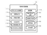
- FIG. 3 shows the main functions of the vehicle allocation planning device 10.
- the vehicle allocation planning device 10 includes the functions of a storage unit 110, an inquiry processing unit 111, a demand estimation unit 112, a vehicle allocation planning unit 113, and an analysis processing unit 114.
- the storage unit 110 stores the inquiry result 151, the demand estimation result 152, the vehicle allocation plan 153, and the analysis result 154.
- the inquiry processing unit 111 transmits the above-described inquiry to the user device 20 existing in the area targeted for the vehicle allocation plan (hereinafter, referred to as a target area), and receives the above-described answer transmitted from the user apparatus 20. .
- the answer received by the inquiry processing unit 111 is stored in the storage unit 110 as an inquiry result 151.
- the demand estimating unit 112 estimates the user's travel demand based on the answer (inquiry result 151).
- the estimated travel demand includes, for example, information that associates information specifying a point (a bus stop, a taxi stand, a bicycle parking area for a shared motorcycle, etc.) with information (demand amount) indicating the magnitude of the travel demand at the point.
- the movement demand estimated by the demand estimation unit 112 is stored in the storage unit 110 as a demand estimation result 152.
- the vehicle allocation planning unit 113 drafts a vehicle allocation plan based on the demand estimation result 152, while taking into account the resources of the transportation (the number of vehicles owned, etc.).
- the vehicle allocation planning device 10 is communicably connected to, for example, an operation management system of a transportation facility, and transmits a planned vehicle allocation plan to the operation management system as needed.
- the vehicle allocation plan created by the vehicle allocation planning unit 113 is stored in the storage unit 110 as the vehicle allocation plan 153.
- the analysis processing unit 114 analyzes the inquiry result 151. As shown in the figure, the analysis processing unit 114 has a similarity calculation unit 1141 and a clustering unit 1142.
- the similarity calculation unit 1141 calculates a similarity between users based on the inquiry result 151.
- the clustering unit 1142 performs user clustering (classification) based on the inquiry result 151.
- the result of the data analysis performed by the analysis processing unit 114 is stored as the analysis result 154 in the storage unit 110.
- the analysis result 154 is used, for example, for estimating the movement demand by the demand estimation unit 112 and for the vehicle allocation plan by the vehicle allocation planning unit 113.
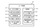
- FIG. 4 shows main functions of the user device 20.
- the user device 20 includes functions of a storage unit 210, a model learning unit 211, an inquiry response unit 212, a utility calculation unit 213, a movement route presentation unit 214, and an inquiry history presentation unit 215.
- the storage unit 210 stores the sensor information 251, the model information 252, and the inquiry history 253.
- the model learning unit 211 performs learning (machine learning) of a utility calculation model described later.
- the storage unit 210 stores the utility calculation model to be learned and the result of the learning as model information 252.
- the inquiry response unit 212 receives the inquiry sent from the vehicle allocation planning device 10, generates an answer to the received inquiry, and transmits the generated response to the vehicle allocation planning device 10.
- the inquiry response unit 212 uses the utility calculation model stored in the storage unit 210 as the model information 252, which is a model for calculating the utility of the user.
- the inquiry response unit 212 generates the answer by determining the utility calculated by the utility calculation model. The above-described determination is performed, for example, by comparing the utility with a preset threshold value or numerical value range.
- the utility calculating unit 213 obtains utility by applying the sensor information 251 to the utility calculation model.
- the model information 252 includes a list of models used as an index and the contents of the models.
- the sensor information 251 includes real-time sensor information acquired by the sensor device 107 and sensor information acquired in the past by the sensor device 107.
- the moving route presenting unit 214 generates a moving route from the starting point to the destination by a predetermined route searching algorithm (for example, a hill-climbing method, a simulated annealing method, a genetic algorithm, a tabu search, etc.) and presents it to the user.
- a predetermined route searching algorithm for example, a hill-climbing method, a simulated annealing method, a genetic algorithm, a tabu search, etc.
- the travel route presenting unit 214 generates a travel route presumably preferable for the user using the utility calculation model, and presents the travel route to the user.
- the inquiry history presenting unit 215 outputs the contents of the inquiry history 253 to the output device 105 and presents it to the user.
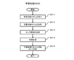
- FIG. 5 is a flowchart illustrating a process in which the model learning unit 211 of the user device 20 estimates a utility calculation model (hereinafter, referred to as a learning process S500).
- the learning process S500 is performed, for example, when an operation of instructing the input device 104 to start learning the utility calculation model is performed.
- the learning process S500 is started, for example, when an instruction to start learning the utility calculation model is received from the vehicle allocation planning device 10.
- the model learning unit 211 receives, via the input device 104, a designation of a utility calculation model to be learned (S511).
- the model learning unit 211 acquires the specified utility calculation model from the model information 252 (S512).
- the model learning unit 211 acquires sensor information used for learning from the sensor information 251 (S513).
- model learning unit 211 performs learning by applying the sensor information 251 acquired in S513 to the utility calculation model acquired in S512 (S514). The details of the learning will be described later.
- model learning unit 211 stores the learning result as model information 252.
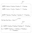
- Fig. 6 shows an example of the utility calculation model. Although the utility calculation model 601 shown in a linear form is shown here, the form of the utility calculation model is not necessarily limited.
- the option is, for example, “get on a bus”
- each item on the right side of the above calculation formula is, for example, “bus travel time” , Utility of bus waiting time, and utility of boarding time.
- the terms on the right side of the above calculation expression are, for example, “Utility of time”, “utilization of fatigue due to walking”, “utilization of user's health consciousness”, and the like.
- the information of each item on the right side of the above calculation formula is obtained from, for example, the user's destination, travel distance, weather, information on accompanying persons, operation delay information obtained from the operation management system, and the like.
- Reference numeral 603 in the figure is a simultaneous equation obtained by substituting the sensor information 602 for a certain timing or a certain scene in the above calculation formula. By solving this simultaneous equation, a coefficient a ij is obtained as a learning result.
- the vehicle allocation planning system 1 of the present embodiment since the learning of the utility calculation model is performed on the user device 20 side, the vehicle allocation includes sensor information that may include personal information and privacy-related information for learning. There is no need to transmit to the planning device 10. It should be noted that the management (storage and version management) of the utility calculation model before learning is performed by, for example, the vehicle allocation planning device 10 in an integrated manner. For example, the utility allocation model is distributed from the vehicle allocation planning device 10 to the user device 20 as needed. You may.
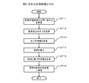
- FIG. 7 illustrates a process performed by the inquiry response unit 212 of the user device 20 when generating a response to the inquiry received from the vehicle allocation planning device 10 and transmitting the generated response to the vehicle allocation planning device 10 (hereinafter, referred to as an inquiry response process S700).
- FIG. 7 illustrates a process performed by the inquiry response unit 212 of the user device 20 when generating a response to the inquiry received from the vehicle allocation planning device 10 and transmitting the generated response to the vehicle allocation planning device 10 (hereinafter, referred to as an inquiry response process S700).
- the inquiry response process S700 will be described with reference to FIG.
- the inquiry response process S700 is started when the inquiry response unit 212 receives an inquiry from the vehicle allocation planning device 10 (S711). Note that the inquiry includes information that specifies one or more utility calculation models used by the user device 20 when generating the answer.
- the inquiry response unit 212 When receiving the inquiry, the inquiry response unit 212 first acquires the utility calculation model designated in the inquiry from the model information 252 (S712).
- the utility calculation unit 213 acquires sensor information from the sensor device 107 (S713).
- the utility calculating unit 213 obtains a utility by applying the sensor information 251 acquired in S713 to the utility model acquired in S712 (S714).
- the sensor information current sensor information may be used, or in some cases, past sensor information stored in the storage unit 210 may be used.
- the utility calculation unit 213 obtains, for example, the utility of each utility calculation model, selects the utility calculation model with the highest utility among them, and uses it to generate an answer.
- the inquiry response unit 212 generates an answer to the inquiry received in S711 based on the obtained utility. For example, if the content of the inquiry is “Is it possible to wait for bus waiting time of 10 minutes?”, The inquiry response unit 212 outputs information indicating “possible” if the calculated utility exceeds a preset threshold value, for example. Is generated as the answer, otherwise, information indicating “impossible” is generated as the answer (S715).
- the inquiry response unit 212 transmits the generated answer to the vehicle allocation planning device 10 (S716).
- the storage unit 210 stores the answer as an inquiry history 253 in association with the contents of the inquiry received from the vehicle allocation planning device 10 in S711.
- the storage unit 110 stores the answer received from the user device 20 as an inquiry result 151.
- the information relating to the user's movement demand is transmitted to the vehicle allocation planning device without sending information relating to the user's behavior (personal information and information relating to privacy) to the vehicle allocation planning device 10. It can be obtained on the 10 side.
- the utility planning model used for generating a response from the vehicle allocation planning device 10 to the user device 20 is designated. By doing so, information according to the intention of the vehicle allocation planning side can be obtained. It can be obtained from the user device 20.
- FIG. 8 shows an example of the inquiry history 253.
- the inquiry history 253 includes one or more records having items of date and time 811, type 812, inquiry content 813, and answer 814.
- Each record of the inquiry history 253 corresponds to one inquiry.
- the inquiry result 151 of the vehicle allocation planning device 10 also includes the same information as the inquiry history 253.
- Each record of the inquiry result 151 of the vehicle allocation planning device 10 further includes information (hereinafter, referred to as a user ID) for identifying the user (user device 20) of the inquiry destination.
- a user ID information for identifying the user (user device 20) of the inquiry destination.
- the date and time 811 is set to the date and time when the inquiry was received.
- the type 812 information indicating the type of the inquiry is set.
- the inquiry content 813 the content of the inquiry received from the vehicle allocation planning device 10 is set.
- the answer 814 the content of the answer generated in S715 of FIG. 7 is set.
- the inquiry history presentation unit 215 of the user device 20 outputs the inquiry history 253 to the output device 105 and presents (visualizes) it to the user in response to a request from the user via the input device 104. Therefore, what kind of inquiry has been received from the vehicle allocation planning device 10 in the past and what kind of answer has been returned to the vehicle allocation planning device 10 in response to the received inquiry (what kind of utility calculation model Is incorporated, and what kind of content has been sent to the vehicle allocation planning device 10) can be confirmed. Therefore, the user can determine, for example, whether or not an answer different from his / her intention has been transmitted to the vehicle allocation planning device 10.
- FIG. 9 is a flowchart illustrating a process (hereinafter, referred to as a moving route presenting process S900) performed by the moving route presenting unit 214 of the user device 20 when presenting the moving route to the user.
- a moving route presentation processing S900 will be described with reference to FIG.
- the travel route presentation process S900 is executed, for example, when the user searches for a travel route using the travel route search function provided by the user device 20.
- the travel route presenting unit 214 receives an input of a travel route search condition via the input device 104 (S911).
- the above search conditions include general search conditions (departure point, destination, transit point, transportation means, departure time, arrival time, etc.) necessary for the search of a travel route, as well as, for example, "prefer walking", Search conditions related to the user's intention, such as "wait for 10 minutes” and "prefer a low price" are included.
- the travel route presenting unit 214 searches for the travel route based on the received search condition, and stores the search result (S912).
- the travel route presenting unit 214 acquires a utility calculation model that matches the search condition received in S911 from the model information 252 (S913).
- the movement route presentation unit 214 acquires the sensor information 251 (S914), and obtains the utility by applying the acquired sensor information 251 to the utility calculation model acquired in S913 (S915).
- the travel route presenting unit 214 determines whether or not the user prefers the travel route of the model (S916). For example, the travel route presenting unit 214 uses the utility calculation model relating to the transportation means for the search condition of “prefers to walk” to “whether the user selects walking in the current situation (for example, rain)”. Is determined. The movement route presenting unit 214 determines whether or not the user prefers the movement route of the model based on, for example, whether or not the utility obtained in S915 exceeds a preset threshold. If a plurality of models have been acquired in S913, the movement route presenting unit 214 makes a determination for each utility calculation model.
- the movement route presenting unit 214 presents the movement route of the utility calculation model to the user via the output device 105. For example, when a travel route (utility calculation model) that uses a bus or taxi transportation means instead of walking is high in utility, the travel route presenting unit 214 gives the user priority over the bus or taxi travel route over the foot travel route. Present. When a plurality of models have been acquired in S913, the moving route presenting unit 214 may present all the moving routes determined to be preferred by the user, or a predetermined number of utility calculating models having a large utility. The moving route may be preferentially presented.
- the travel route presenting unit 214 presents the travel route searched in S913 to the user via the output device 105.
- FIG. 10 is an example of a screen (hereinafter, referred to as a moving route presenting screen 1000) displayed on the output device 105 by the moving route presenting unit 214 in the processing from S916 to S918 in FIG.
- a diagram for explaining a movement route is displayed in a display column indicated by reference numeral 1011.
- O represents a departure place
- D represents a destination
- a ⁇ B represents a bus route
- B ⁇ C represents a train route.
- Search conditions (“departure place O”, “destination D”, “arrival by 10:55”) are displayed in a display column indicated by reference numeral 1012. Further, a search result is displayed in a display column indicated by reference numeral 1013.
- the search route “departure point O”, “destination D”, and “arrival by 10:55” displayed in the display column 1012 indicate the travel route presented in S917 of FIG.
- the “alternative plan” and the travel route “plan 1” presented in S918 of FIG. 9 are displayed in the display column 1013.
- the user device 20 uses the utility calculation model to determine whether or not the user prefers the travel route, and presents the travel route determined to be preferred by the user. Can be appropriately selected.
- the travel route presenting unit 214 transmits the travel route information presented to the user to the vehicle allocation planning device 10, and the vehicle allocation planning device 10 estimates the user's travel demand and makes a vehicle allocation plan based on the information. Is also good.
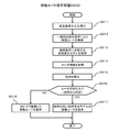
- FIG. 11 is a flowchart illustrating a process (hereinafter referred to as a vehicle allocation planning process S1100) performed by the vehicle allocation planning unit 113 of the vehicle allocation planning device 10 when planning a vehicle allocation plan.
- a vehicle allocation planning process S1100 will be described with reference to FIG.
- the vehicle allocation planning unit 113 makes the above-mentioned inquiry to the user (user device 20) existing in the target area (S1111). Note that, upon receiving the above inquiry, the user device 20 executes an inquiry response process S700 shown in FIG. 7 and transmits an answer to the vehicle allocation planning device 10.
- the vehicle allocation planning unit 113 receives a response to the inquiry from the user device 20 (S1112).
- the vehicle allocation planning unit 113 selects a user who is supposed to accept the vehicle allocation plan (for example, arrangement of a temporary bus) to be planned (S1113).
- the vehicle allocation plan unit 113 transmits a vehicle allocation plan and an inquiry as to whether or not to accept the vehicle allocation plan to the user device 20 of the selected user (S1114), and receives a response to the inquiry from the user device 20 (S1114). S1115).
- the dispatch plan unit 113 drafts a dispatch plan based on the received response (S1116).
- the planning of the dispatching plan is performed, for example, by transmitting the utility for each user (user device 20) to the dispatching planning apparatus 10, and the dispatching planning unit 113 is configured to maximize the utility of the plurality of users, that is, the When the utility is modeled as a constraint expression and a penalty function when deviating from the constraint expression, the constraint violation is minimized.
- the vehicle allocation planning unit 113 transmits the result of the planning to a device that uses the planning result, such as an operation management system (S1117).
- the vehicle allocation planning system 1 of the present embodiment does not require the vehicle allocation planning device 10 to acquire information on the behavior of the user (for example, sensor information acquired by the sensor device 107 of the user device 20), It is possible to formulate a vehicle allocation plan according to the movement demand and provide it to an operation management system or the like.
- the analysis processing unit 114 of the vehicle allocation planning device 10 analyzes the inquiry result 151, and the analysis result is managed in the storage unit 110 as the analysis result 154.
- This analysis result 154 can be used, for example, in estimating a user's demand by the demand estimating unit 112 and in a vehicle allocation plan by the vehicle allocation planning unit 113.
- the analysis result 154 can be used, for example, for marketing, regional characteristic analysis, and the like.
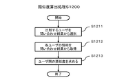
- FIG. 12 is a flowchart illustrating processing performed by the similarity calculation section 1141 of the analysis processing section 114 (hereinafter, referred to as similarity calculation processing S1200).
- similarity calculation processing S1200 will be described with reference to FIG.
- the similarity calculation unit 1141 selects two users to be compared from the inquiry result 151 (S1211).
- the similarity calculation unit 1141 acquires information of each selected user from the inquiry result 151 (S1212).
- the similarity calculation unit 1141 obtains the similarity (for example, cosine similarity) of the acquired information of each user (S1113).
- the similarity calculated by the similarity calculation unit 1141 is stored in the storage unit 110 as the analysis result 154.
- the similarity calculation unit 1141 performs the above-described similarity calculation processing S1200, for example, for all combinations of users included in the inquiry result 151.
- the demand estimating unit 112 it is possible to estimate a user's demand by the demand estimating unit 112 and to specify users to be treated in the same queue in the dispatching plan by the dispatching planning unit 113. For example, a traffic common to users having similar preferences can be specified. It is possible to draft an efficient vehicle allocation plan by providing means.
- FIG. 13 is a flowchart illustrating a process (hereinafter, referred to as a clustering process S1300) performed by the clustering unit 1142 of the analysis processing unit 114 when performing user clustering (classification).
- a clustering process S1300 will be described with reference to FIG.
- the clustering unit 1142 receives settings of a plurality of users to be clustered via the input device 104 (S1311). Note that a plurality of users to be clustered may be set in advance and stored in the vehicle allocation planning device 10 in advance. Further, all users in the inquiry result 151 may be set as a target of clustering.
- the clustering unit 1142 acquires information of each of a plurality of users to be clustered from the query result 151 (S1312).
- the clustering unit 1142 converts the acquired information of each user into a vector (S1313).
- the clustering unit 1142 clusters the vectorized information by a predetermined clustering method such as the k-means method (S1314).
- the clustering unit 1142 generates information indicating the result of the clustering (S1315).
- the generated information is stored in the storage unit 110 as the analysis result 154.
- the tendency of the user can be grasped.
- it can be used for marketing, regional characteristic analysis, and the like.
- the user device 20 substitutes the sensor information into the utility calculation model to determine the utility, and the user device 20 sends the utility to the vehicle allocation planning device 10. Since the generated answer is transmitted, the sensor information (information on behavior) is not transmitted to the vehicle allocation planning device 10, and a vehicle allocation plan according to the user's intention is made while protecting the user's personal information and information on privacy. Can be.
- the present invention has been specifically described based on the embodiments, the present invention is not limited to the above embodiments, and can be variously modified without departing from the gist thereof.
- the above-described embodiment has been described in detail in order to explain the present invention in an easy-to-understand manner, and is not necessarily limited to one having all the described configurations. Further, for a part of the configuration of the above embodiment, other configurations can be added, deleted, or replaced.
- the above-described configurations, functional units, processing units, processing means, and the like may be partially or entirely realized by hardware, for example, by designing an integrated circuit.
- Each of the above configurations, functions, and the like may be implemented by software by a processor interpreting and executing a program that implements each function.
- Information such as a program, a table, and a file for realizing each function can be stored in a recording device such as a memory, a hard disk, an SSD (Solid State Drive), or a recording medium such as an IC card, an SD card, or a DVD.
- control lines and information lines are considered to be necessary for explanation, and do not necessarily indicate all control lines and information lines on mounting. For example, it may be considered that almost all components are actually connected to each other.
- the arrangement of the various functional units, various processing units, and various databases of the information processing apparatus described above is merely an example.
- the arrangement of the various functional units, the various processing units, and the various databases can be changed to the optimal arrangement for each information processing apparatus from the viewpoint of hardware and software performance, processing efficiency, communication efficiency, and the like.
- 1 vehicle allocation planning system 5 communication network, 10 vehicle allocation planning device, 20 user device, 100 information processing device, 104 input device, 105 output device, 107 sensor device, 111 inquiry processing unit, 112 demand estimating unit, 113 vehicle allocation planning unit, 114 analysis processing unit, 1141 similarity calculation unit, 1142 clustering unit, 151 inquiry result, 152 demand estimation result, 153 vehicle allocation plan, 154 analysis result, 211 model learning unit, 212 inquiry response unit, 213 utility calculation unit, 214 travel route Presentation section, 215 inquiry history presentation section, 251 sensor information, 252 model information, 253 inquiry history, S500 learning processing, S700 inquiry response processing, S900 travel route presentation processing, 1000 travel route Presentation screen, S1100 vehicle allocation planning process, S1200 similarity calculation processing, S1300 clustering processing
Landscapes
- Engineering & Computer Science (AREA)
- Remote Sensing (AREA)
- Radar, Positioning & Navigation (AREA)
- Business, Economics & Management (AREA)
- Physics & Mathematics (AREA)
- General Physics & Mathematics (AREA)
- Human Resources & Organizations (AREA)
- Theoretical Computer Science (AREA)
- Strategic Management (AREA)
- Economics (AREA)
- Automation & Control Theory (AREA)
- Data Mining & Analysis (AREA)
- Entrepreneurship & Innovation (AREA)
- General Business, Economics & Management (AREA)
- Marketing (AREA)
- Tourism & Hospitality (AREA)
- Software Systems (AREA)
- Artificial Intelligence (AREA)
- General Engineering & Computer Science (AREA)
- Computer Vision & Pattern Recognition (AREA)
- Evolutionary Computation (AREA)
- General Health & Medical Sciences (AREA)
- Health & Medical Sciences (AREA)
- Quality & Reliability (AREA)
- Operations Research (AREA)
- Game Theory and Decision Science (AREA)
- Educational Administration (AREA)
- Development Economics (AREA)
- Medical Informatics (AREA)
- Social Psychology (AREA)
- Computing Systems (AREA)
- Mathematical Physics (AREA)
- Evolutionary Biology (AREA)
- Bioinformatics & Computational Biology (AREA)
- Bioinformatics & Cheminformatics (AREA)
- Life Sciences & Earth Sciences (AREA)
- Primary Health Care (AREA)
- Management, Administration, Business Operations System, And Electronic Commerce (AREA)
- Traffic Control Systems (AREA)
Abstract
ユーザの行動に関する情報の取り扱いに配慮しつつユーザの意向に沿った配車計画を立案する。配車計画システムは、交通機関の配車計画を立案する配車計画装置と配車計画装置と通信可能に接続されるユーザ装置とを備える。配車計画装置は、ユーザの移動需要に関する問い合わせをユーザ装置に送信し、問い合わせに対する回答を受信し、回答に基づきユーザの移動需要を推定し、推定した移動需要に基づき配車計画を立案する。ユーザ装置は、自身の現在または過去の状態を示す情報であるセンサ情報と、移動時におけるユーザの効用を求める効用算出モデルとを記憶し、センサ情報を効用算出モデルに適用してユーザの効用を求め、上記問い合わせについて、求めた上記効用に基づき回答を生成し、生成した回答を配車計画装置に送信する。
Description
本発明は、交通機関における配車計画システム、情報処理装置、及び配車計画システムの制御方法に関する。
本出願は、2018年10月3日に出願された日本特許出願2018-188055号に基づく優先権を主張し、その開示全体を援用して本出願に取り込むものである。
ICT(Information and Communication Technology)の進展に伴い、バスやタクシー等の交通機関の配車計画は従来よりも動的かつ柔軟に行われるようになってきている。配車計画においては如何にしてユーザの意向に沿った計画を立てるかが課題となる。
特許文献1には、デマンド交通車両を効率的に運用しつつ、より多くの乗客の利用要求を受け付けるデマンド交通車両の配車計画を作成することを目的として構成されたデマンド交通運用システムについて記載されている。デマンド交通運用システムは、相乗り型デマンド交通車両の希望出発時刻及び希望到着時刻の少なくともいずれか一方と出発地と目的地とを含む複数の乗客の旅程要求を受信し、旅程要求を規定時刻よりも前に受信しかつ希望到着時刻又は希望出発時刻が規定期間内にあることを規定条件として乗客を区別してデマンド交通車両の配車計画を作成する。
特許文献2には、交通機関を利用するユーザの利便性を高めつつ、ユーザを効率よく目的地へ運ぶことを目的として構成された乗車意向判定装置について記載されている。乗車意向判定装置は、移動体に乗車するための乗車地点を示す乗車位置情報と、ユーザの現在地を示すユーザ位置情報との間での位置関係を取得し、取得された位置関係と、ユーザの行動を示す行動情報とに基づいて、ユーザが移動体に乗車する意向があるか否かを判定し、ユーザの行動を示す行動情報が所定の条件情報を満たす場合として、移動体に乗車するための乗車地点に関するコンテンツをユーザが閲覧した場合に、ユーザが移動体に乗車する意向があると判定する。
上記の特許文献1,2においては、出発地や目的地、現在地等のユーザ(利用者)の行動に関する情報をシステム側に送信している。昨今、個人情報保護やプライバシー保護に対する意識の高まりにより、個人情報やプライバシーに関する情報の取り扱いに対する制限が年々厳しくなってきている。そのため、今後は特許文献1,2のようにユーザの行動に関する情報を事業者側で収集することを前提としたシステムの実現は難しくなっていくものと予想される。
本発明はこうした背景に鑑みてなされたもので、ユーザの行動に関する情報の取り扱いに配慮しつつユーザの意向に沿った配車計画を立案することが可能な、配車計画システム、情報処理装置、及び配車計画システムの制御方法を提供することを目的としている。
上記課題を解決するための本発明の一つは、配車計画システムであって、交通機関の配車計画を立案する情報処理装置である配車計画装置と、前記配車計画装置と通信可能に接続され、前記交通機関のユーザによって操作される情報処理装置であるユーザ装置と、を備え、前記配車計画装置は、前記ユーザの移動に関する意向を示す情報である移動需要に関する問い合わせを前記ユーザ装置に送信し、前記問い合わせに対する回答を受信する問い合わせ処理部と、前記回答に基づき前記ユーザの移動需要を推定する需要推定部と、推定した前記移動需要に基づき前記配車計画を立案する配車計画部と、を有し、前記ユーザ装置は、自身の現在または過去の状態を示す情報であるセンサ情報と、移動時におけるユーザの効用を求める効用算出モデルとを記憶する記憶部と、前記センサ情報を前記効用算出モデルに適用して前記ユーザの効用を求める効用算出部と、前記配車計画装置から受信した前記問い合わせについて、前記効用に基づき前記回答を生成し、生成した回答を前記配車計画装置に送信する問い合わせ応答部と、を有する。
その他、本願が開示する課題、及びその解決方法は、発明を実施するための形態の欄、及び図面により明らかにされる。
本発明によれば、ユーザの行動に関する情報の取り扱いに配慮しつつユーザの意向に沿った配車計画を立案することができる。
以下、図面を適宜参照しつつ実施形態について説明する。以下の説明において、共通する構成について共通の符号を付して重複した説明を省略することがある。
図1に一実施形態として示す配車計画システム1の概略的な構成を示している。同図に示すように、配車計画システム1は、交通機関(路線バス、シャトルバス、オンデマンドバス、タクシー、シェアバイク等)の車両の配車計画を立案する配車計画装置10と、通信ネットワーク5を介して配車計画装置10と通信可能に接続された一つ以上のユーザ装置20とを含む。通信ネットワーク5は、無線方式または有線方式の通信手段であり、例えば、インターネット、携帯電話網、LAN(Local Area Network)、WAN(Wide Area Network)、専用線等である。
配車計画装置10は、交通事業者等の組織の管理者によって管理される情報処理装置(コンピュータ)であり、例えば、パーソナルコンピュータ、サーバ装置、メインフレーム等である。配車計画装置10は、ユーザ装置20に移動(出発地から目的地までの移動)に関するユーザの意向(いずれの移動手段を選択しいずれの移動ルートを選択するか等)を示す情報である移動需要に関する問い合わせを行い、ユーザ装置20から送られてくる上記の問い合わせに対する回答を受信する。配車計画装置10は、受信した回答に基づきユーザの移動需要を推定し、推定した結果に基づき配車計画を立案する。尚、上記問い合わせの回答は、ユーザの行動に関する情報(個人情報やプライバシーに関する情報に相当する可能性のあるもの)を含まない。
ユーザ装置20は、交通機関のユーザが利用する情報処理装置(コンピュータ)であり、スマートフォン、タブレット、携帯電話機、パーソナルコンピュータ等である。ユーザ装置20は、交通機関に関する情報や各種サービスをユーザに提供する。
図2は配車計画装置10やユーザ装置20を構成するハードウェアの一例(以下、情報処理装置100と称する。)である。同図に示すように、情報処理装置100は、プロセッサ101、主記憶装置102、補助記憶装置103、入力装置104、出力装置105、及び通信装置106を備える。またユーザ装置20を構成する情報処理装置100は、以上の構成に加えてさらにセンサ装置107を備える。情報処理装置100の各構成は図示しないバス等の通信手段を介して互いに通信可能に接続されている。尚、情報処理装置100は、構成の全部又は一部がクラウドシステム(cloud system)のクラウドサーバ(cloud server)のような仮想的な資源によって実現されるものであってもよい。
プロセッサ101は、CPU(Central Processing Unit)、MPU(Micro Processing Unit)等を用いて構成される。プロセッサ101が、主記憶装置102に格納されているプログラムを読み出して実行することにより、配車計画装置10やユーザ装置20が備える機能が実現される。
主記憶装置102は、プログラムやデータを記憶する装置であり、ROM(Read Only Memory)、RAM(Random Access Memory)、不揮発性半導体メモリ(NVRAM(Non Volatile RAM))等である。
補助記憶装置103は、例えば、SSD(Solid State Drive)、SDメモリカード等の各種不揮発性メモリ(NVRAM:Non-volatile memory)、ハードディスクドライブ、光学式記憶装置(CD(Compact Disc)、DVD(Digital Versatile Disc)等)、クラウドサーバの記憶領域等である。補助記憶装置103に格納されているプログラムやデータは主記憶装置102に随時読み込まれる。
入力装置104は、情報の入力を受け付けるインタフェースであり、例えば、キーボード、マウス、タッチパネル、カードリーダ、マイクロフォン等である。情報処理装置100が通信装置106を介して他の装置との間で情報の入力を受け付ける構成としてもよい。またセンサ装置107を入力装置104として機能させてもよい。
出力装置105は、各種の情報を出力するインタフェースであり、例えば、画面表示装置(液晶モニタ、LCD(Liquid Crystal Display)、グラフィックカード等)、印字装置等)、音声出力装置(スピーカ等)等である。情報処理装置100が、通信装置106を介して他の装置との間で情報の出力を行う構成としてもよい。
通信装置106は、通信ネットワーク5を介した他の装置との間の通信を実現する有線方式又は無線方式の通信インタフェースであり、例えば、NIC(Network Interface Card)、無線通信モジュール、USB(Universal Serial Interface)モジュール、シリアル通信モジュール等である。
センサ装置107は、例えば、自己位置検出センサ(GPS(Grobal Positioning System)センサ、Wi-Fi)、加速度センサ、ジャイロセンサ、方位センサ等であり、ユーザ装置20の現在地等のユーザの状態に関する情報(以下、センサ情報と称する。)を出力する。
図3に配車計画装置10が備える主な機能を示している。同図に示すように、配車計画装置10は、記憶部110、問い合わせ処理部111、需要推定部112、配車計画部113、及び分析処理部114の各機能を備える。
上記構成のうち、記憶部110は、問い合わせ結果151、需要推定結果152、配車計画153、及び分析結果154を記憶する。
問い合わせ処理部111は、配車計画の対象となる地域(以下、対象地域と称する。)に存在するユーザ装置20に前述した問い合わせを送信し、ユーザ装置20から送られてくる前述の回答を受信する。問い合わせ処理部111が受信した上記回答は、記憶部110が問い合わせ結果151として記憶する。
需要推定部112は、上記回答(問い合わせ結果151)に基づきユーザの移動需要を推定する。推定する移動需要は、例えば、地点(バス停、タクシー乗り場、シェアバイクの駐輪場等)を特定する情報と当該地点における移動需要の大きさを表す情報(需要量)とを対応づけた情報を含む。需要推定部112が推定した移動需要は、記憶部110が需要推定結果152として記憶する。
配車計画部113は、需要推定結果152に基づき、交通機関のリソース(保有する車両の数等)を考慮しつつ配車計画を立案する。配車計画装置10は、例えば、交通機関の運行管理システムと通信可能に接続されており、立案した配車計画を運行管理システムに随時送信する。配車計画部113が立案した配車計画は記憶部110が配車計画153として記憶する。
分析処理部114は、問い合わせ結果151の分析を行う。同図に示すように、分析処理部114は、類似度算出部1141とクラスタリング部1142とを有する。類似度算出部1141は、問い合わせ結果151に基づきユーザ間の類似度を求める。またクラスタリング部1142は、問い合わせ結果151に基づきユーザのクラスタリング(分類)を行う。分析処理部114が行ったデータ分析の結果は、記憶部110が分析結果154として記憶する。分析結果154は、例えば、需要推定部112による移動需要の推定や配車計画部113による配車計画に利用される。
図4にユーザ装置20が備える主な機能を示している。同図に示すように、ユーザ装置20は、記憶部210、モデル学習部211、問い合わせ応答部212、効用算出部213、移動ルート提示部214、及び問い合わせ履歴提示部215の各機能を備える。
上記構成のうち、記憶部210は、センサ情報251、モデル情報252、及び問い合わせ履歴253を記憶する。
モデル学習部211は、後述する効用算出モデルの学習(機械学習)を行う。記憶部210は、学習対象となる効用算出モデルや上記学習の結果をモデル情報252として記憶する。
問い合わせ応答部212は、配車計画装置10から送られてくる問い合わせを受信し、受信した問い合わせに対する回答を生成して配車計画装置10に送信する。上記回答の生成に際し、問い合わせ応答部212は、記憶部210がモデル情報252として記憶している、ユーザの効用を算出するモデルである効用算出モデルを用いる。問い合わせ応答部212は、効用算出モデルにより算出した効用を判定することにより上記回答を生成する。上記判定は、例えば、効用を予め設定された閾値や数値範囲と比較することにより行われる。
効用算出部213は、効用算出モデルにセンサ情報251を適用することにより効用を求める。モデル情報252は、インデックスとして用いられるモデルの一覧とモデルの内容とを含む。センサ情報251は、センサ装置107によって取得されるリアルタイムなセンサ情報やセンサ装置107によって過去に取得されたセンサ情報を含む。
移動ルート提示部214は、所定の経路探索アルゴリズム(例えば、山登り法、シミュレーテッドアニーリング法、遺伝的アルゴリズム、タブーサーチ等)により出発地から目的地に至る移動ルートを生成してユーザに提示する。また移動ルート提示部214は、効用算出モデルを用いてユーザにとって好ましいと推定される移動ルートを生成してユーザに提示する。
問い合わせ履歴提示部215は、問い合わせ履歴253の内容を出力装置105に出力してユーザに提示する。
図5は、ユーザ装置20のモデル学習部211が効用算出モデルを推定する処理(以下、学習処理S500と称する。)を説明するフローチャートである。以下、同図とともに学習処理S500について説明する。尚、学習処理S500は、例えば、入力装置104に対して効用算出モデルの学習の開始を指示する操作が行われたことを契機として行われる。また学習処理S500は、例えば、配車計画装置10から効用算出モデルの学習の開始指示を受信したことを契機として開始される。
同図に示すように、まずモデル学習部211は、入力装置104を介して、学習しようとする効用算出モデルの指定を受け付ける(S511)。
続いて、モデル学習部211は、指定された効用算出モデルをモデル情報252から取得する(S512)。
続いて、モデル学習部211は、学習に用いるセンサ情報をセンサ情報251から取得する(S513)。
続いて、モデル学習部211は、S512で取得した効用算出モデルにS513で取得したセンサ情報251を適用して学習を行う(S514)。尚、上記学習の詳細については後述する。
続いて、モデル学習部211は学習結果をモデル情報252として記憶する。
図6に効用算出モデルの例を示す。尚、ここでは線形式で表された効用算出モデル601を示すが、効用算出モデルの態様は必ずしも限定されない。
同図に示す一群の効用算出モデル601の夫々は、「バスに乗る」、「歩いていく」といったユーザの選択肢の夫々について設定された効用fi(x)(i=0,1,2,・・・m)の算出式である。選択肢が例えば「バスに乗る」である場合、上記算出式の右辺の各項(例えば、a01x01,a02x02,・・・,a0nx0n)は、例えば「バスの移動時間の効用」、「バスの待ち時間の不効用」、「乗車時間の不効用」等である。また選択肢が例えば「歩いていく」である場合、上記算出式の右辺の各項(例えば、a11x11,a12x12,・・・,a1nx1n)は、例えば「徒歩の移動時間の効用」、「徒歩による疲労の不効用」、「ユーザの健康意識の効用」等である。尚、上記算出式の右辺の各項の情報は、例えば、ユーザの目的地や移動距離、天候、同行者に関する情報、運行管理システムから取得される運行遅延情報等から取得される。
効用算出モデルの学習は、上記算出式の右辺の変数(a01x02,・・・,a12x12,・・・)をセンサ情報に基づき決定していくことにより行われる。同図における符号602はセンサ情報の例であるskは目的変数であり、t01k,t02k,t03k,・・・,t0nk はその他のセンサ情報(説明変数)である。
同図における符号603は、上記算出式にあるタイミングやある場面におけるセンサ情報602を代入することにより得られる連立方程式である。この連立方程式を解くことにより学習結果として係数aijが求められる。
以上のように、本実施形態の配車計画システム1においては、効用算出モデルの学習をユーザ装置20側で行うので、学習のために個人情報やプライバシーに関する情報を含む可能性のあるセンサ情報を配車計画装置10に送信する必要がない。尚、学習前の効用算出モデルの管理(保管やバージョン管理)については、例えば、配車計画装置10側で統括して行うようにし、例えば、配車計画装置10からユーザ装置20に随時配信するようにしてもよい。
図7はユーザ装置20の問い合わせ応答部212が、配車計画装置10から受信した問い合わせに対して回答を生成して配車計画装置10に送信する際に行う処理(以下、問い合わせ応答処理S700と称する。)を説明するフローチャートである。以下、同図とともに問い合わせ応答処理S700について説明する。
問い合わせ応答処理S700は、問い合わせ応答部212が配車計画装置10から問い合わせを受信したことを契機として開始される(S711)。尚、上記の問い合わせは、上記回答を生成する際にユーザ装置20が用いる一つ以上の効用算出モデルを指定する情報を含む。
問い合わせを受信すると、まず問い合わせ応答部212は、上記問い合わせに指定されている効用算出モデルをモデル情報252から取得する(S712)。
続いて、効用算出部213は、センサ装置107からセンサ情報を取得する(S713)。
続いて、効用算出部213は、S712で取得した効用対象モデルにS713で取得したセンサ情報251を適用して効用を求める(S714)。ここでセンサ情報は、現在のセンサ情報を用いてもよいし、場合によっては記憶部210が記憶している過去のセンサ情報を用いてもよい。問い合わせに指定されている効用算出モデルが複数である場合、効用算出部213は、例えば、各効用算出モデルの効用を求め、そのうち最も効用の高い効用算出モデルを選択して回答の生成に用いる。
続いて、問い合わせ応答部212は、求めた効用に基づきS711で受信した問い合わせに対する回答を生成する。例えば、問い合わせの内容が「バス待ち時間10分まで可能か?」であった場合、問い合わせ応答部212は、例えば、算出した効用が予め設定された閾値を超えていれば「可能」を示す情報を上記回答として生成し、それ以外の場合は「不可能」を示す情報を上記回答として生成する(S715)。
続いて、問い合わせ応答部212は、生成した上記回答を配車計画装置10に送信する(S716)。
尚、記憶部210は、上記回答をS711で配車計画装置10から受信した問い合わせの内容に対応づけて問い合わせ履歴253として記憶する。また配車計画装置10では、記憶部110が、ユーザ装置20から受信した上記回答を問い合わせ結果151として記憶する。
以上のように、本実施形態の配車計画システム1によれば、ユーザの行動に関する情報(個人情報やプライバシーに関する情報)を配車計画装置10に送ることなく、ユーザの移動需要に関する情報を配車計画装置10側で取得することができる。尚、本例では配車計画装置10からユーザ装置20に対して回答の生成に際して用いる効用算出モデルを指定しているが、そのようにすることで配車計画を立案する側の意向に沿った情報をユーザ装置20から取得することができる。
図8に問い合わせ履歴253の一例を示す。同図に示すように、問い合わせ履歴253は、日時811、種別812、問い合わせ内容813、及び回答814の各項目を有する一つ以上のレコードを含む。問い合わせ履歴253の各レコードは一つの問い合わせに対応している。尚、配車計画装置10の問い合わせ結果151も問い合わせ履歴253と同様の情報を含む。また配車計画装置10の問い合わせ結果151の各レコードは、さらに問い合わせ先のユーザ(ユーザ装置20)を識別する情報(以下、ユーザIDと称する。)を含む。
上記項目のうち、日時811には、当該問い合わせを受信した日時が設定される。種別812には、当該問い合わせの種別を示す情報が設定される。問い合わせ内容813には、配車計画装置10から受信した問い合わせの内容が設定される。回答814には、図7のS715で生成した回答の内容が設定される。
尚、ユーザ装置20の問い合わせ履歴提示部215は、入力装置104を介したユーザからの要求に応じて、問い合わせ履歴253を出力装置105に出力してユーザに提示(可視化)する。そのため、ユーザは、過去に配車計画装置10からどの様な問い合わせを受信し、受信した問い合わせに対してどのような回答を配車計画装置10に返したのか(ユーザ装置20にどのような効用算出モデルが組み込まれており、どのような内容が配車計画装置10に送られたのか)を確認することができる。そのため、ユーザは、例えば、自身の意向とは異なる回答が配車計画装置10に送信されているか否かを判断することができる。
図9は、ユーザ装置20の移動ルート提示部214が、ユーザに移動ルートを提示する際に行う処理(以下、移動ルート提示処理S900と称する。)を説明するフローチャートである。以下、同図とともに移動ルート提示処理S900について説明する。移動ルート提示処理S900は、例えば、ユーザがユーザ装置20が提供する移動ルートの検索機能を利用して移動ルートの検索を行う際に実行される。
まず移動ルート提示部214は、入力装置104を介して移動ルートの検索条件の入力を受け付ける(S911)。上記の検索条件は、移動ルートの検索に必要な一般的な検索条件(出発地、目的地、経由地、交通手段、出発時間、到着時間等)の他、例えば、「徒歩を嗜好する」、「10分まで待つ」、「低価格を嗜好する」といったユーザの意向に関する検索条件を含む。
続いて、移動ルート提示部214は、受け付けた検索条件に基づき移動ルートを検索し、検索結果を記憶する(S912)。
続いて、移動ルート提示部214は、S911で受け付けた検索条件に合致する効用算出モデルをモデル情報252から取得する(S913)。
続いて、移動ルート提示部214は、センサ情報251を取得し(S914)、取得したセンサ情報251をS913で取得した効用算出モデルに適用して効用を求める(S915)。
続いて、移動ルート提示部214は、S915で求めた効用に基づき、ユーザが当該モデルの移動ルートを好むか否かを判定する(S916)。例えば、移動ルート提示部214は、「徒歩を嗜好する」という検索条件に対して移動手段に関する効用算出モデルを用いることにより「今の状況(例えば雨)でユーザが徒歩を選択するか否か」を判定する。移動ルート提示部214は、例えば、S915で求めた効用が予め設定された閾値を超えているか否かに基づき、ユーザが当該モデルの移動ルートを好むか否かを判定する。尚、S913で複数のモデルを取得している場合、移動ルート提示部214は各効用算出モデルについて判定を行う。
ユーザが効用算出モデルによる移動ルートを好むと判定した場合(S916:YES)、移動ルート提示部214は、当該効用算出モデルの移動ルートを出力装置105を介してユーザに提示する。例えば、徒歩ではなくバスやタクシーの移動手段を用いる移動ルート(効用算出モデル)の効用が高い場合、移動ルート提示部214は、バスやタクシーの移動ルートを徒歩の移動ルートに優先してユーザに提示する。尚、S913で複数のモデルを取得している場合、移動ルート提示部214がユーザが好むと判定した全ての移動ルートを提示するようにしてもよいし、効用が大きい所定数の効用算出モデルの移動ルートを優先的に提示するようにしてもよい。
S916において、ユーザが当該効用算出モデルの移動ルートを好まないと判定した場合(S916:NO)、移動ルート提示部214は、S913で検索した移動ルートを出力装置105を介してユーザに提示する。
図10は、図9のS916からS918の処理に際して移動ルート提示部214が出力装置105に表示する画面(以下、移動ルート提示画面1000と称する。)の一例である。同図において、符号1011で示す表示欄には、移動ルートを説明する図が表示されている。上記表示欄においてOは出発地、Dは目的地、A→Bはバスのルート、B→Cは電車のルートを表している。符号1012で示す表示欄には、検索条件(「出発地O」、「目的地D」、「10:55までに到着」)が表示されている。また符号1013で示す表示欄には検索結果が表示されている。本例の場合、表示欄1012に表示されている「出発地O」、「目的地D」、「10:55までに到着」という検索条件に対して、図9のS917で提示される移動ルート「代替案」と、図9のS918で提示される移動ルート「案1」とが表示欄1013に表示されている。
以上のように、ユーザ装置20は、効用算出モデルを利用して移動ルートをユーザが好むか否かを判定し、ユーザが好むと判定した移動ルートを提示するので、ユーザは自身の意向に沿った移動ルートを適切に選択することができる。尚、移動ルート提示部214がユーザに提示した移動ルートの情報を配車計画装置10に送信し、配車計画装置10が上記情報に基づきユーザの移動需要の推定や配車計画の立案を行うようにしてもよい。
図11は、配車計画装置10の配車計画部113が配車計画を立案する際に行う処理(以下、配車計画立案処理S1100)を説明するフローチャートである。以下、同図とともに配車計画立案処理S1100について説明する。
まず配車計画部113は、対象地域に存在するユーザ(ユーザ装置20)に対して前述の問い合わせを行う(S1111)。尚、ユーザ装置20は、上記問い合わせを受信すると、図7に示した問い合わせ応答処理S700を実行して配車計画装置10に回答を送信する。
続いて、配車計画部113は、ユーザ装置20から問い合わせに対する回答を受信する(S1112)。
続いて、配車計画部113は、受信した回答に基づき、立案しようとしている配車計画(例えば、臨時バスの手配等)を受け入れると想定されるユーザを選択する(S1113)。
続いて、配車計画部113は、選択したユーザのユーザ装置20に配車計画と当該配車計画を受け入れるか否かの問い合わせとを送信し(S1114)、ユーザ装置20から上記問い合わせに対する応答を受信する(S1115)。
続いて、配車計画部113は、受信した上記応答に基づき配車計画を立案する(S1116)。配車計画の立案は、例えば、ユーザ(ユーザ装置20)毎の効用を配車計画装置10に送信し、配車計画部113が、複数のユーザ全体の効用が最大化されるように、即ち、ユーザの効用を制約式と当該制約式を逸脱したときのペナルティ関数としてモデル化した場合に制約違反が最小化されるように行われる。
続いて、配車計画部113は、立案した結果を、運行管理システム等の当該立案結果を利用する装置に送信する(S1117)。
このように、本実施形態の配車計画システム1は、配車計画装置10側でユーザの行動に関する情報(例えば、ユーザ装置20のセンサ装置107により取得されたセンサ情報)を取得することなく、ユーザの移動需要に沿った配車計画を立案して運行管理システム等に提供することができる。
ところで、前述したように、配車計画装置10の分析処理部114は、問い合わせ結果151の分析を行い、当該分析の結果は、記憶部110が分析結果154として管理される。この分析結果154は、例えば、需要推定部112によるユーザの需要推定や、配車計画部113による配車計画において利用することができる。また分析結果154は、例えば、マーケッティングや地域の特性分析等に活用することができる。
図12は、分析処理部114の類似度算出部1141が行う処理(以下、類似度算出処理S1200と称する。)を説明するフローチャートである。以下、同図とともに類似度算出処理S1200について説明する。
類似度算出部1141は、まず問い合わせ結果151から、比較しようとする2人のユーザを選択する(S1211)。
続いて、類似度算出部1141は、選択した各ユーザの情報を問い合わせ結果151から取得する(S1212)。
続いて、類似度算出部1141は、取得した各ユーザの情報の類似度(例えばコサイン類似度)を求める(S1113)。類似度算出部1141が求めた上記類似度は、記憶部110が分析結果154として記憶する。
尚、類似度算出部1141は、以上の類似度算出処理S1200を、例えば、問い合わせ結果151に含まれている全てのユーザの組み合わせについて行う。
以上によれば、例えば、需要推定部112によるユーザの需要推定や、配車計画部113による配車計画において同列に扱うべきユーザを特定することができ、例えば、類似する嗜好を有するユーザに共通の交通手段を提供する等して効率的な配車計画を立案することが可能になる。
図13は、分析処理部114のクラスタリング部1142がユーザのクラスタリング(分類)を行う際に行う処理(以下、クラスタリング処理S1300と称する。)を説明するフローチャートである。以下、同図とともにクラスタリング処理S1300について説明する。
まずクラスタリング部1142は、入力装置104を介してクラスタリングの対象となる複数のユーザの設定を受け付ける(S1311)。尚、クラスタリングの対象となる複数のユーザを事前に設定しておき予め配車計画装置10に記憶しておくようにしてもよい。また問い合わせ結果151における全てのユーザをクラスタリングの対象としてもよい。
続いて、クラスタリング部1142は、クラスタリングの対象となる複数のユーザの夫々の情報を問い合わせ結果151から取得する(S1312)。
続いて、クラスタリング部1142は、取得した各ユーザの情報をベクトル化する(S1313)。
続いて、クラスタリング部1142は、ベクトル化された情報をk-means法等の所定のクラスタリング手法によりクラスタリングする(S1314)。
続いて、クラスタリング部1142は、クラスタリングの結果を示す情報を生成する(S1315)。尚、生成された上記情報は記憶部110が分析結果154として記憶する。
以上のクラスタリング処理S1300により得られた分析結果154を用いることで、例えば、ユーザの傾向(歩くのが好き、階段が好き、待つのはとても嫌い、寄り道はしない等)を把握することができ、例えば、マーケッティングや地域の特性分析等に利用することができる。
以上に説明したように、本実施形態の配車計画システム1によれば、ユーザ装置20側でセンサ情報を効用算出モデルに代入して効用を求め、ユーザ装置20から配車計画装置10へは効用に基づき生成した回答を送信するので、配車計画装置10にセンサ情報(行動に関する情報)を送信されず、ユーザの個人情報やプライバシーに関する情報を保護しつつユーザの意向に沿った配車計画を立案することができる。
以上、本発明について実施の形態に基づき具体的に説明したが、本発明は上記の実施の形態に限定されるものではなく、その要旨を逸脱しない範囲で種々変更可能である。例えば、上記の実施の形態は本発明を分かりやすく説明するために詳細に説明したものであり、必ずしも説明した全ての構成を備えるものに限定されるものではない。また上記実施形態の構成の一部について、他の構成の追加、削除、置換をすることができる。
また上記の各構成、機能部、処理部、処理手段等は、それらの一部または全部を、例えば、集積回路で設計する等によりハードウェアで実現してもよい。また上記の各構成、機能等は、プロセッサが夫々の機能を実現するプログラムを解釈し、実行することによりソフトウェアで実現してもよい。各機能を実現するプログラム、テーブル、ファイル等の情報は、メモリやハードディスク、SSD(Solid State Drive)等の記録装置、またはICカード、SDカード、DVD等の記録媒体に置くことができる。
また各図において、制御線や情報線は説明上必要と考えられるものを示しており、必ずしも実装上の全ての制御線や情報線を示しているとは限らない。例えば、実際にはほとんど全ての構成が相互に接続されていると考えてもよい。
また以上に説明した情報処理装置の各種機能部、各種処理部、各種データベースの配置形態は一例に過ぎない。各種機能部、各種処理部、各種データベースの配置形態は、各情報処理装置がハードウェアやソフトウェアの性能、処理効率、通信効率等の観点から最適な配置形態に変更し得る。
1 配車計画システム、5 通信ネットワーク、10 配車計画装置、20 ユーザ装置、100 情報処理装置、104 入力装置、105 出力装置、107 センサ装置、111 問い合わせ処理部、112 需要推定部、113 配車計画部、114 分析処理部、1141 類似度算出部、1142 クラスタリング部、151 問い合わせ結果、152 需要推定結果、153 配車計画、154 分析結果、211 モデル学習部、212 問い合わせ応答部、213 効用算出部、214 移動ルート提示部、215 問い合わせ履歴提示部、251 センサ情報、252 モデル情報、253 問い合わせ履歴、S500 学習処理、S700 問い合わせ応答処理、S900 移動ルート提示処理、1000 移動ルート提示画面、S1100 配車計画立案処理、S1200 類似度算出処理、S1300 クラスタリング処理
Claims (15)
- 交通機関の配車計画を立案する情報処理装置である配車計画装置と、
前記配車計画装置と通信可能に接続され、前記交通機関のユーザによって操作される情報処理装置であるユーザ装置と、
を備え、
前記配車計画装置は、
前記ユーザの移動に関する意向を示す情報である移動需要に関する問い合わせを前記ユーザ装置に送信し、前記問い合わせに対する回答を受信する問い合わせ処理部と、
前記回答に基づき前記ユーザの移動需要を推定する需要推定部と、
推定した前記移動需要に基づき前記配車計画を立案する配車計画部と、
を有し、
前記ユーザ装置は、
自身の現在または過去の状態を示す情報であるセンサ情報と、移動時におけるユーザの効用を求める効用算出モデルとを記憶する記憶部と、
前記センサ情報を前記効用算出モデルに適用して前記ユーザの効用を求める効用算出部と、
前記配車計画装置から受信した前記問い合わせについて、前記効用に基づき前記回答を生成し、生成した回答を前記配車計画装置に送信する問い合わせ応答部と、
を有する、
配車計画システム。 - 請求項1に記載の配車計画システムであって、
前記ユーザ装置は、複数の前記効用算出モデルを記憶する記憶部をさらに有し、
前記効用算出部は、前記配車計画装置から受信した前記問い合わせについて、前記センサ情報を複数の前記効用算出モデルの夫々に適用して前記複数の効用算出モデルの夫々から効用を求め、
前記問い合わせ応答部は、前記複数の効用算出モデルのうち効用が最も高い前記効用算出モデルの効用に基づき生成した前記回答を前記配車計画装置に送信する、
配車計画システム。 - 請求項1に記載の配車計画システムであって、
前記ユーザ装置は、
複数の前記効用算出モデルを記憶する記憶部と、
前記ユーザの移動ルートの検索条件に合致する前記効用算出モデルを取得し、前記センサ情報を前記効用算出モデルに適用して効用を求め、求めた効用が最も高い前記効用算出モデルに対応する移動ルートを生成して前記ユーザに提示する移動ルート提示部と、
をさらに有する、配車計画システム。 - 請求項1に記載の配車計画システムであって、
前記ユーザ装置は、複数の前記効用算出モデルを記憶する記憶部をさらに有し、
前記配車計画装置は、前記問い合わせを前記ユーザ装置に送信する際、前記ユーザ装置が前記回答の生成に際して用いる効用算出モデルを指定する情報を送信し、
前記ユーザ装置の前記効用算出部は、前記問い合わせを受信した場合に、前記センサ情報を前記情報で指定される前記効用算出モデルに適用して効用を求め、
前記問い合わせ応答部は、前記効用に基づき生成した前記回答を前記配車計画装置に送信する、
配車計画システム。 - 請求項1に記載の配車計画システムであって、
前記ユーザ装置は、前記センサ情報に基づき前記効用算出モデルを学習するモデル学習部をさらに有する、配車計画システム。 - 請求項1に記載の配車計画システムであって、
前記ユーザ装置は、
前記問い合わせの内容と当該問い合わせについての前記回答の内容とを対応づけた情報である問い合わせ履歴を記憶する記憶部と、
前記問い合わせ履歴の内容を出力する問い合わせ履歴提示部と、
をさらに有する、配車計画システム。 - 請求項1に記載の配車計画システムであって、
前記配車計画装置は、
複数の前記ユーザ装置から受信した前記ユーザ毎の前記回答を記憶する記憶部と、
前記ユーザ毎の前記回答の類似度を算出する類似度算出部と、
をさらに有し、
前記需要推定部は、前記ユーザの移動需要の推定に際し前記類似度を用いる、
配車計画システム。 - 請求項1に記載の配車計画システムであって、
前記配車計画装置は、
複数の前記ユーザ装置から受信した前記ユーザ毎の前記回答を記憶する記憶部と、
前記ユーザ毎の回答に基づき前記ユーザをクラスタリングするクラスタリング部と、
をさらに有し、
前記需要推定部は、前記ユーザの移動需要の推定に際し前記クラスタリングの結果を用いる、
配車計画システム。 - 請求項1に記載の配車計画システムにおける前記配車計画装置として機能する情報処理装置であって、
前記ユーザの移動に関する意向を示す情報である移動需要に関する問い合わせを前記ユーザ装置に送信し、前記問い合わせに対する回答を受信する、前記問い合わせ処理部と、
前記回答に基づき前記ユーザの移動需要を推定する、前記需要推定部と、
推定した前記移動需要に基づき前記配車計画を立案する、前記配車計画部と、
を有する、情報処理装置。 - 請求項1に記載の配車計画システムにおける前記ユーザ装置として機能する情報処理装置であって、
自身の現在または過去の状態を示す情報であるセンサ情報と、移動時におけるユーザの効用を求める効用算出モデルとを記憶する、前記記憶部と、
前記センサ情報を前記効用算出モデルに適用して前記ユーザの効用を求める、前記効用算出部と、
前記配車計画装置から受信した前記問い合わせについて、前記効用に基づき前記回答を生成し、生成した回答を前記配車計画装置に送信する、前記問い合わせ応答部と、
を有する、
情報処理装置。 - 交通機関の配車計画を立案する情報処理装置である配車計画装置と、前記配車計画装置と通信可能に接続され、前記交通機関のユーザによって操作される情報処理装置であるユーザ装置と、を備えて構成される、配車計画システムの制御方法であって、
前記配車計画装置が、
前記ユーザの移動に関する意向を示す情報である移動需要に関する問い合わせを前記ユーザ装置に送信し、前記問い合わせに対する回答を受信するステップと、
前記回答に基づき前記ユーザの移動需要を推定するステップと、
推定した前記移動需要に基づき前記配車計画を立案するステップと、
を実行し、
前記ユーザ装置が、
自身の現在または過去の状態を示す情報であるセンサ情報と、移動時におけるユーザの効用を求める効用算出モデルとを記憶するステップと、
前記センサ情報を前記効用算出モデルに適用して前記ユーザの効用を求めるステップと、
前記配車計画装置から受信した前記問い合わせについて、前記効用に基づき前記回答を生成し、生成した回答を前記配車計画装置に送信するステップと、
を実行する、
配車計画システムの制御方法。 - 請求項11に記載の配車計画システムの制御方法であって、
前記ユーザ装置が、
複数の前記効用算出モデルを記憶するステップと、
前記配車計画装置から受信した前記問い合わせについて、前記センサ情報を複数の前記効用算出モデルの夫々に適用して前記複数の効用算出モデルの夫々から効用を求めるステップと、
前記複数の効用算出モデルのうち効用が最も高い前記効用算出モデルの効用に基づき生成した前記回答を前記配車計画装置に送信するステップと、
をさらに実行する、
配車計画システムの制御方法。 - 請求項11に記載の配車計画システムの制御方法であって、
前記ユーザ装置が、
複数の前記効用算出モデルを記憶するステップと、
前記ユーザの移動ルートの検索条件に合致する前記効用算出モデルを取得し、前記センサ情報を前記効用算出モデルに適用して効用を求め、求めた効用が最も高い前記効用算出モデルに対応する移動ルートを生成して前記ユーザに提示するステップと、
をさらに実行する、
配車計画システムの制御方法。 - 請求項11に記載の配車計画システムの制御方法であって、
前記ユーザ装置が、複数の前記効用算出モデルを記憶するステップをさらに実行し、
前記配車計画装置が、前記問い合わせを前記ユーザ装置に送信する際、前記ユーザ装置が前記回答の生成に際して用いる効用算出モデルを指定する情報を送信するステップをさらに実行し、
前記ユーザ装置が、
前記問い合わせを受信した場合に、前記センサ情報を前記情報で指定される前記効用算出モデルに適用して効用を求めるステップと、
前記効用に基づき生成した前記回答を前記配車計画装置に送信するステップと、
をさらに実行する、
配車計画システムの制御方法。 - 請求項11に記載の配車計画システムの制御方法であって、
前記ユーザ装置が、前記センサ情報に基づき前記効用算出モデルを学習するステップをさらに実行する、配車計画システムの制御方法。
Priority Applications (2)
| Application Number | Priority Date | Filing Date | Title |
|---|---|---|---|
| EP19868811.1A EP3862965A4 (en) | 2018-10-03 | 2019-10-01 | VEHICLE ALLOCATION PLANNING SYSTEM, INFORMATION PROCESSING DEVICE AND METHOD FOR CONTROLLING A VEHICLE ALLOCATION PLANNING SYSTEM |
| US17/270,463 US11928618B2 (en) | 2018-10-03 | 2019-10-01 | Transport allocation planning system, information processing apparatus, and method for controlling transport allocation planning system |
Applications Claiming Priority (2)
| Application Number | Priority Date | Filing Date | Title |
|---|---|---|---|
| JP2018188055A JP7001569B2 (ja) | 2018-10-03 | 2018-10-03 | 配車計画システム、情報処理装置、及び配車計画システムの制御方法 |
| JP2018-188055 | 2018-10-03 |
Publications (1)
| Publication Number | Publication Date |
|---|---|
| WO2020071352A1 true WO2020071352A1 (ja) | 2020-04-09 |
Family
ID=70055167
Family Applications (1)
| Application Number | Title | Priority Date | Filing Date |
|---|---|---|---|
| PCT/JP2019/038718 Ceased WO2020071352A1 (ja) | 2018-10-03 | 2019-10-01 | 配車計画システム、情報処理装置、及び配車計画システムの制御方法 |
Country Status (4)
| Country | Link |
|---|---|
| US (1) | US11928618B2 (ja) |
| EP (1) | EP3862965A4 (ja) |
| JP (1) | JP7001569B2 (ja) |
| WO (1) | WO2020071352A1 (ja) |
Families Citing this family (5)
| Publication number | Priority date | Publication date | Assignee | Title |
|---|---|---|---|---|
| WO2020097221A1 (en) | 2018-11-08 | 2020-05-14 | Evangelos Simoudis | Systems and methods for managing vehicle data |
| EP4222687A4 (en) * | 2020-09-30 | 2024-04-03 | Synapse Partners, LLC | TRANSPORT MARKETPLACE SYSTEMS AND PROCEDURES |
| JP7547986B2 (ja) * | 2020-12-17 | 2024-09-10 | トヨタ自動車株式会社 | 情報処理装置、情報処理方法、及び、システム |
| CN115719193A (zh) * | 2022-12-05 | 2023-02-28 | 井松机器人(杭州)有限公司 | 一种物联网的物流车辆调度规划系统 |
| KR102850667B1 (ko) * | 2022-12-12 | 2025-08-27 | 주식회사 카카오모빌리티 | 경로 안내와 연동된 자율주행 소프트웨어의 검색과 학습에 의한 자율주행 제어 방법 및 장치 |
Citations (6)
| Publication number | Priority date | Publication date | Assignee | Title |
|---|---|---|---|---|
| JPS6310606B2 (ja) | 1979-03-02 | 1988-03-08 | Tokyo Shibaura Electric Co | |
| JPS6341352B2 (ja) | 1983-07-15 | 1988-08-16 | Hitachi Ltd | |
| JP2007249918A (ja) * | 2006-03-20 | 2007-09-27 | Hitachi Software Eng Co Ltd | 携帯型端末を用いたタクシー配車システム |
| JP2014130552A (ja) * | 2012-12-29 | 2014-07-10 | Zmp Co Ltd | タクシーサービス支援システム |
| JP2017091351A (ja) * | 2015-11-13 | 2017-05-25 | 日本電気株式会社 | 統合装置、統合方法、統合プログラム、および制御システム |
| JP2018188055A (ja) | 2017-05-10 | 2018-11-29 | 大日本印刷株式会社 | 照明装置及び車両 |
Family Cites Families (10)
| Publication number | Priority date | Publication date | Assignee | Title |
|---|---|---|---|---|
| US20040107110A1 (en) * | 2002-12-02 | 2004-06-03 | Jens Gottlieb | Optimization of transport with multiple vehicles |
| EP2624178A1 (en) * | 2008-06-05 | 2013-08-07 | Telefonaktiebolaget L M Ericsson (publ) | A method of providing a car pooling assistance through a wireless communication system |
| FR2935523B1 (fr) * | 2008-08-29 | 2010-11-05 | Alcatel Lucent | Procede et systeme de mise en relation automatique et en direct d'un conducteur et d'au moins une personne a transporter. |
| US10901426B2 (en) * | 2012-07-31 | 2021-01-26 | Transportation Ip Holdings, Llc | Vehicle control system |
| US20150176997A1 (en) * | 2013-12-22 | 2015-06-25 | Andreas Kurt PURSCHE | Adaptive transportation framework |
| US10677602B2 (en) * | 2017-01-25 | 2020-06-09 | Via Transportation, Inc. | Detecting the number of vehicle passengers |
| JP6941974B2 (ja) * | 2017-05-30 | 2021-09-29 | 株式会社日立製作所 | 輸送計画生成方法および輸送計画生成システム |
| JP6310606B1 (ja) | 2017-09-20 | 2018-04-11 | ヤフー株式会社 | 乗車意図判定装置、乗車意図判定方法および乗車意図判定プログラム |
| US20200249047A1 (en) * | 2017-10-25 | 2020-08-06 | Ford Global Technologies, Llc | Proactive vehicle positioning determinations |
| WO2019106745A1 (ja) | 2017-11-29 | 2019-06-06 | 三菱電機株式会社 | デマンド交通運用システム |
-
2018
- 2018-10-03 JP JP2018188055A patent/JP7001569B2/ja active Active
-
2019
- 2019-10-01 WO PCT/JP2019/038718 patent/WO2020071352A1/ja not_active Ceased
- 2019-10-01 US US17/270,463 patent/US11928618B2/en active Active
- 2019-10-01 EP EP19868811.1A patent/EP3862965A4/en not_active Withdrawn
Patent Citations (6)
| Publication number | Priority date | Publication date | Assignee | Title |
|---|---|---|---|---|
| JPS6310606B2 (ja) | 1979-03-02 | 1988-03-08 | Tokyo Shibaura Electric Co | |
| JPS6341352B2 (ja) | 1983-07-15 | 1988-08-16 | Hitachi Ltd | |
| JP2007249918A (ja) * | 2006-03-20 | 2007-09-27 | Hitachi Software Eng Co Ltd | 携帯型端末を用いたタクシー配車システム |
| JP2014130552A (ja) * | 2012-12-29 | 2014-07-10 | Zmp Co Ltd | タクシーサービス支援システム |
| JP2017091351A (ja) * | 2015-11-13 | 2017-05-25 | 日本電気株式会社 | 統合装置、統合方法、統合プログラム、および制御システム |
| JP2018188055A (ja) | 2017-05-10 | 2018-11-29 | 大日本印刷株式会社 | 照明装置及び車両 |
Non-Patent Citations (1)
| Title |
|---|
| See also references of EP3862965A4 |
Also Published As
| Publication number | Publication date |
|---|---|
| JP7001569B2 (ja) | 2022-01-19 |
| EP3862965A1 (en) | 2021-08-11 |
| US20210325199A1 (en) | 2021-10-21 |
| JP2020057247A (ja) | 2020-04-09 |
| US11928618B2 (en) | 2024-03-12 |
| EP3862965A4 (en) | 2022-07-06 |
Similar Documents
| Publication | Publication Date | Title |
|---|---|---|
| WO2020071352A1 (ja) | 配車計画システム、情報処理装置、及び配車計画システムの制御方法 | |
| KR101960140B1 (ko) | 자율 주행 차량 내에서 증강 가상 현실 콘텐츠를 제공하는 시스템 및 방법 | |
| JP6606532B2 (ja) | 自律走行車のために車両群を管理する方法及びシステム | |
| CN107577227B (zh) | 操作无人驾驶车辆的方法、装置和数据处理系统 | |
| JP2020057247A5 (ja) | ||
| US10003924B2 (en) | Method of and server for processing wireless device sensor data to generate an entity vector associated with a physical location | |
| US20140257989A1 (en) | Method and system for selecting in-vehicle advertisement | |
| JP2018531385A (ja) | 自律走行車を運行させるための制御エラー補正計画方法 | |
| JP2018531385A6 (ja) | 自律走行車を運行させるための制御エラー補正計画方法 | |
| US11580856B2 (en) | Identification of a poorly parked vehicle and performance of a first group of actions to cause one or more other devices to perform a second group of actions | |
| JP6723721B2 (ja) | 旅行プランナーのための旅行再ランキング | |
| JP7067350B2 (ja) | 情報処理装置および情報処理方法 | |
| JP2017162450A (ja) | 公共交通機関システムにおけるユーザ旅行嗜好の平滑化動的モデリング | |
| CN106663260B (zh) | 信息提示装置、方法以及程序 | |
| CN106920038A (zh) | 无人驾驶车辆的调度方法、装置、设备及存储介质 | |
| CN110832477A (zh) | 基于传感器的语义对象生成 | |
| JP7017143B2 (ja) | 情報処理装置、および情報処理方法、並びにプログラム | |
| US10915928B2 (en) | Product solution responsive to problem identification | |
| CN107533564A (zh) | 在数字助理上提供个性化问候 | |
| WO2019042350A1 (zh) | 高精度电子地图的处理方法、装置、设备及计算机可读存储介质 | |
| CN108701280A (zh) | 确定语义行进模式 | |
| JP2012133583A (ja) | ランドマーク推薦装置及び方法及びプログラム | |
| JP7476847B2 (ja) | 方法、情報処理装置、及びプログラム | |
| US20240230353A1 (en) | Cost Based Navigation and Route Planning | |
| CN108701141A (zh) | 确定语义行进模式 |
Legal Events
| Date | Code | Title | Description |
|---|---|---|---|
| 121 | Ep: the epo has been informed by wipo that ep was designated in this application |
Ref document number: 19868811 Country of ref document: EP Kind code of ref document: A1 |
|
| NENP | Non-entry into the national phase |
Ref country code: DE |
|
| ENP | Entry into the national phase |
Ref document number: 2019868811 Country of ref document: EP Effective date: 20210503 |