WO2020075480A1 - 計測装置、計測方法、プログラム - Google Patents
計測装置、計測方法、プログラム Download PDFInfo
- Publication number
- WO2020075480A1 WO2020075480A1 PCT/JP2019/037020 JP2019037020W WO2020075480A1 WO 2020075480 A1 WO2020075480 A1 WO 2020075480A1 JP 2019037020 W JP2019037020 W JP 2019037020W WO 2020075480 A1 WO2020075480 A1 WO 2020075480A1
- Authority
- WO
- WIPO (PCT)
- Prior art keywords
- measurement
- unit
- image
- target
- measurement target
- Prior art date
- Legal status (The legal status is an assumption and is not a legal conclusion. Google has not performed a legal analysis and makes no representation as to the accuracy of the status listed.)
- Ceased
Links
Images










Classifications
-
- G—PHYSICS
- G01—MEASURING; TESTING
- G01N—INVESTIGATING OR ANALYSING MATERIALS BY DETERMINING THEIR CHEMICAL OR PHYSICAL PROPERTIES
- G01N21/00—Investigating or analysing materials by the use of optical means, i.e. using sub-millimetre waves, infrared, visible or ultraviolet light
- G01N21/17—Systems in which incident light is modified in accordance with the properties of the material investigated
- G01N21/25—Colour; Spectral properties, i.e. comparison of effect of material on the light at two or more different wavelengths or wavelength bands
- G01N21/251—Colorimeters; Construction thereof
-
- A—HUMAN NECESSITIES
- A01—AGRICULTURE; FORESTRY; ANIMAL HUSBANDRY; HUNTING; TRAPPING; FISHING
- A01D—HARVESTING; MOWING
- A01D46/00—Picking of fruits, vegetables, hops, or the like; Devices for shaking trees or shrubs
- A01D46/30—Robotic devices for individually picking crops
-
- G—PHYSICS
- G01—MEASURING; TESTING
- G01D—MEASURING NOT SPECIALLY ADAPTED FOR A SPECIFIC VARIABLE; ARRANGEMENTS FOR MEASURING TWO OR MORE VARIABLES NOT COVERED IN A SINGLE OTHER SUBCLASS; TARIFF METERING APPARATUS; MEASURING OR TESTING NOT OTHERWISE PROVIDED FOR
- G01D21/00—Measuring or testing not otherwise provided for
-
- G—PHYSICS
- G01—MEASURING; TESTING
- G01J—MEASUREMENT OF INTENSITY, VELOCITY, SPECTRAL CONTENT, POLARISATION, PHASE OR PULSE CHARACTERISTICS OF INFRARED, VISIBLE OR ULTRAVIOLET LIGHT; COLORIMETRY; RADIATION PYROMETRY
- G01J3/00—Spectrometry; Spectrophotometry; Monochromators; Measuring colours
- G01J3/28—Investigating the spectrum
- G01J3/30—Measuring the intensity of spectral lines directly on the spectrum itself
- G01J3/36—Investigating two or more bands of a spectrum by separate detectors
-
- G—PHYSICS
- G01—MEASURING; TESTING
- G01N—INVESTIGATING OR ANALYSING MATERIALS BY DETERMINING THEIR CHEMICAL OR PHYSICAL PROPERTIES
- G01N21/00—Investigating or analysing materials by the use of optical means, i.e. using sub-millimetre waves, infrared, visible or ultraviolet light
- G01N21/17—Systems in which incident light is modified in accordance with the properties of the material investigated
- G01N21/25—Colour; Spectral properties, i.e. comparison of effect of material on the light at two or more different wavelengths or wavelength bands
- G01N21/31—Investigating relative effect of material at wavelengths characteristic of specific elements or molecules, e.g. atomic absorption spectrometry
- G01N21/314—Investigating relative effect of material at wavelengths characteristic of specific elements or molecules, e.g. atomic absorption spectrometry with comparison of measurements at specific and non-specific wavelengths
-
- G—PHYSICS
- G01—MEASURING; TESTING
- G01N—INVESTIGATING OR ANALYSING MATERIALS BY DETERMINING THEIR CHEMICAL OR PHYSICAL PROPERTIES
- G01N21/00—Investigating or analysing materials by the use of optical means, i.e. using sub-millimetre waves, infrared, visible or ultraviolet light
- G01N21/17—Systems in which incident light is modified in accordance with the properties of the material investigated
- G01N21/25—Colour; Spectral properties, i.e. comparison of effect of material on the light at two or more different wavelengths or wavelength bands
- G01N21/31—Investigating relative effect of material at wavelengths characteristic of specific elements or molecules, e.g. atomic absorption spectrometry
- G01N21/35—Investigating relative effect of material at wavelengths characteristic of specific elements or molecules, e.g. atomic absorption spectrometry using infrared light
- G01N21/3554—Investigating relative effect of material at wavelengths characteristic of specific elements or molecules, e.g. atomic absorption spectrometry using infrared light for determining moisture content
-
- G—PHYSICS
- G01—MEASURING; TESTING
- G01N—INVESTIGATING OR ANALYSING MATERIALS BY DETERMINING THEIR CHEMICAL OR PHYSICAL PROPERTIES
- G01N33/00—Investigating or analysing materials by specific methods not covered by groups G01N1/00 - G01N31/00
- G01N33/02—Food
- G01N33/025—Fruits or vegetables
-
- G—PHYSICS
- G06—COMPUTING OR CALCULATING; COUNTING
- G06T—IMAGE DATA PROCESSING OR GENERATION, IN GENERAL
- G06T7/00—Image analysis
-
- A—HUMAN NECESSITIES
- A01—AGRICULTURE; FORESTRY; ANIMAL HUSBANDRY; HUNTING; TRAPPING; FISHING
- A01G—HORTICULTURE; CULTIVATION OF VEGETABLES, FLOWERS, RICE, FRUIT, VINES, HOPS OR SEAWEED; FORESTRY; WATERING
- A01G3/00—Cutting implements specially adapted for horticultural purposes; Delimbing standing trees
- A01G3/02—Secateurs; Flower or fruit shears
Definitions
- the present technology relates to a measuring device, a measuring method, and a program, and particularly to a technology that can be used for measuring the characteristic amount of a measurement target in various work processes.
- an object of the present technology is to be able to appropriately specify a measurement target without requiring an extra action load or operation load on a user (worker) in a work process involving measurement by a measurement device.
- a measuring device includes a measurement target specifying unit that performs a process of specifying a measurement target based on detection of gripping of an object by a gripping body, and measurement of a feature amount of the measurement target specified by the measurement target specifying unit. And a measurement unit that obtains a measurement result by processing.
- the gripping body is, for example, a hand or a finger of a worker, a hand or a finger of a worker wearing gloves or a predetermined device, a device capable of gripping an object by a human operation, a device capable of automatically gripping an object. , A robot arm or the like that can hold an object.
- Objects refer to various objects such as agricultural products such as grapes, bananas and tomatoes, natural objects such as trees and animals, and industrial products, and the measurement target object is, of these objects, all or all of the objects specified by gripping. Become a part.
- the feature amount refers to a number, size, color, component content, component ratio, sugar content, water content, estimated price, etc. that can be quantified or compared and evaluated.
- the measurement device includes a presentation control unit that performs processing for presentation based on the measurement result. That is, the presentation control unit performs control for causing the feature amount measured by the measurement unit and information based on the feature amount to be presented by display, voice, vibration, or the like. For example, a process of presenting measurement information and determination information based on the measurement information is performed.
- the measurement process is performed using a captured image.
- a captured image obtained by capturing an object with an integrated or separate imaging device is input.
- the feature amount that can be determined from the image is measured.
- the measurement process is performed based on detection that an object is gripped by the grip body. That is, when the grasping of the object by the grasping body is detected, the measurement of the feature amount of the measurement object is started.
- the measurement process is performed based on detection that an object is grasped by the grasping body and the object is moved.
- the measurement of the feature amount of the measurement target is started when some movement is applied to the object while being gripped.
- the movement is supposed to be shaken, pinched and moved up and down, left and right, back and forth, and rotated.
- the measurement process is performed based on the grip of the object by the grip body and the detection of a predetermined action other than the grip.
- a predetermined action is performed, and the measurement of the feature amount of the measurement target is started.
- the predetermined action is assumed to be a vocalization of the worker, a sound action such as generating a predetermined sound, or a gesture action by the worker's hand or tool (scissors, etc.).
- the measurement process is performed using images of a plurality of frames captured during a period in which the measurement target is moving. For example, a captured image obtained by capturing an object with an integrated or separate imaging device is input, but measurement is performed using a plurality of frames of an image obtained as a moving image, for example.
- the measurement target specifying unit uses the object held by the gripper and moved as the measurement target.
- the measurement target For example, an object or a part of the object to which some movement is applied in the gripped state is set as the measurement object.
- the movement is supposed to be pinched and moved up and down, left and right, back and forth, shaken, and rotated.
- the measuring device includes a target setting unit that sets a target value of the feature amount, and the target setting unit obtains a difference value between the feature amount measured in the measurement process and the target value. It is possible.
- the target value of the feature amount is set and stored by user setting or automatic setting so that it can be compared with the measured value.
- the measurement device may include a presentation control unit that performs processing for presenting the difference value.
- the presentation control unit presents the difference between the current feature amount and the target value by a method such as display or voice.
- the movement is rotational movement.
- the measurement is started by detecting that the object is rotated while being gripped.
- the grip body is either a human hand, a device operated by a human, or a robot arm that automatically operates.
- the measurement target specifying unit detects a grip by a human hand as a gripping body, an instrument, or a robot arm, and specifies a measurement target.
- the human hand includes a bare hand and a gloved hand.
- An instrument refers to any instrument that can be grasped by a person's intention in any form, such as an instrument operated by a person by hand, an instrument operated by a person other than the hand, an instrument mounted on the hand, an instrument operated remotely, etc.
- the robot arm refers to one that can be grasped by automatic control.
- the object to be measured may be an agricultural product. That is, the measurement target specifying unit specifies, as the measurement target, the individual of the gripped agricultural product among the agricultural products.
- the term “crop” as used herein means a crop in a broad sense and includes fruits, vegetables, grains, trees, flowers, mushrooms, fertilizers, feeds, horticultural crops, industrial crops, and the like.
- the measurement target specifying unit performs a process of setting a bunch of grapes whose branches are gripped by the gripping body as a measurement target, and in the measurement process, a measurement target is set. It is conceivable to measure the number of grains as a characteristic amount of a bunch of grapes. A bunch of grapes with branches removed is used as the measurement target, and the number of grains in the bunch is measured.
- the measurement device includes an image capturing unit that captures an image used for the measurement processing.
- an image capturing unit that captures an image used for the measurement processing.
- an integrated or separate imaging unit is provided.
- the measuring device includes an imaging unit that captures an image used in the measurement process, and a presentation unit that presents the measurement result, and the imaging unit and the presentation unit are worn on the body. It may be arranged in the mold unit.
- the body-worn unit is a unit that can be worn on a person's body or clothes, and has, for example, a head mount type, eyeglass type, earphone type, wristband type, clothing type, clip type, pocket storage type, pendant type, or the like. is assumed.
- the imaging unit and the presentation unit are arranged in such a body-worn unit.
- the presentation unit can present the measurement result to the user, and refers to, for example, a display unit, a voice output unit, a vibration unit, or the like that can present some information to the user's five senses.
- the presentation unit is a display unit that displays information on a display surface arranged in front of the user's eyes.
- a head-mounted type or a spectacle type is used, and information such as measurement results is displayed on a display unit arranged in front of the user's eyes.
- a sensor unit that detects gripping of an object by the gripping body is provided.
- a sensor unit that detects gripping of an object by a gripping body such as a human hand, an instrument, or a robot arm
- an imaging device that detects an image, pressure, temperature information, distance measurement information, a pressure sensor, a thermotracer, a distance measurement Sensors etc. are assumed.
- a measurement method includes a process of specifying a measurement target object based on detection of gripping of an object by a gripping body, and a process of obtaining a measurement result by measuring a feature amount of the specified measurement target object. Is what you do. That is, the information processing apparatus realizes an appropriate specifying process of the measurement target.
- a program according to an embodiment of the present technology is a program that causes an information processing device to execute the above-described processing of specifying a measurement target and processing of obtaining a measurement result. This realizes an information processing device that can specify the measurement target.
- the measurement method starts a process of specifying a grape tuft to be measured based on detection of gripping of a grape tuft by a gripping body, and measuring the number of grains of the specified grape tuft.
- the information processing device performs processing.
- the information processing device performs a process of identifying the bunch of grapes grasped by the grasping body and a process of measuring the number of grains of the identified bunch of grapes in accordance with the rotation of the identified bunch of grapes.
- FIG. 1 shows a configuration example of the measuring device 1 according to the embodiment.
- the measuring device 1 in this example includes an imaging unit 2, an image signal processing unit 3, an image analysis unit 4, a control unit 5, an operation unit 6, a sensor unit 7, a display control unit 8, a display unit 9, and a storage unit 10.
- the image capturing unit 2 is capable of capturing an image of an object to be measured, for example, grapes being cultivated in a vineyard.
- the image pickup unit 2 may be, for example, a normal visible light camera for obtaining at least an object image or a camera having a distance measuring function for measuring a distance to a subject.
- a camera having a distance measuring function an image for detecting a distance measuring method such as an STL (Structured Light) method or a ToF (Time of Flight) method together with an image sensor for capturing an image. It is conceivable that the camera is equipped with a sensor or configured as a stereo camera.
- the imaging unit 2 is a camera equipped with an image sensor such as a near-infrared camera, a multi-spectral camera, or a specific wavelength imaging camera that captures an image for measurement with a specific wavelength. Can also be considered. Further, the image capturing section 2 may be configured to capture a temperature distribution image as a thermo tracer.
- the image sensor mounted on the image pickup unit 2 is an image pickup device such as a CCD (Charge Coupled Device) sensor or a CMOS (Complementary Metal Oxide Semiconductor) sensor, and the image sensor from the subject incident through the image pickup optical system in the image pickup unit 2 is used. It receives light, converts it into an electrical signal, and outputs it.
- This image sensor one driven by a global shutter system or a rolling shutter system can be considered.
- the image sensor performs, for example, CDS (Correlated Double Sampling) processing, AGC (Automatic Gain Control) processing, etc. on an electric signal obtained by photoelectrically converting the received light, and further A / D (Analog / Digital) conversion processing. I do. Then, the image signal as digital data is output to the image signal processing unit 3 in the subsequent stage.
- the image signal processing unit 3 is configured as an image processor such as a DSP (Digital Signal Processor).
- the image signal processing unit 3 performs various processes on the image signal as digital data input from the imaging unit 2. For example, the image signal processing unit 3 clamps the black level of R (red), G (green), and B (blue) to a predetermined level when an image signal is assumed as a normal visible light image. Correction processing between G and B color channels, demosaic processing for making image data for each pixel have all R, G and B color components, and generation of a luminance (Y) signal and a color (C) signal ( Separation) is performed.
- DSP Digital Signal Processor
- the image signal processing unit 3 may perform necessary resolution conversion processing, for example, resolution conversion for recording, communication output, or monitor image, on the image signal subjected to various signal processing.
- the image signal processing unit 3 may also perform, for example, recording or communication compression processing or encoding processing on the resolution-converted image data.
- the image analysis unit 4 extracts the frame of the image signal that has been subjected to the predetermined processing in the image signal processing unit 3 and performs image analysis processing for measurement. For example, the type and operation state of an object as a subject is determined by a method such as pattern matching, the area or attribute of an object for measuring a feature amount is determined, or measurement based on the determination is performed.
- the image analysis unit 4 analyzes each frame (or intermittent frame) during capturing of a moving image as a processing target, and performs a process of determining the situation on the subject side or obtaining information for the determination. For example, information for determining a situation regarding a grasped body or an object or determining a state such as a grasp is calculated. Further, the feature amount may be measured from the frame being imaged.
- the image analysis unit 4 reads out the image data captured by the image capturing unit 2 and stored in the storage unit 10 as a processing target, and performs analysis on an object as a subject, for example, measurement of a feature amount or calculation of information for measurement. It can be carried out.
- the information determined by the image analysis unit 4 is supplied to the control unit 5 and used for a series of processing for measurement.
- the image analysis unit 4 is configured as an AI (artificial intelligence) engine, performs image recognition processing based on machine learning, deep learning, and the like to enable, for example, determination of an object, recognition of a state of a gripping body, and recognition of a feature amount. You may make it possible to recognize the part regarding measurement.
- AI artificial intelligence
- the control unit 5 is configured by a microcomputer (arithmetic processing device) including a CPU (Central Processing Unit), a ROM (Read Only Memory), a RAM (Random Access Memory), a flash memory, and the like.
- the CPU executes the program stored in the ROM, the flash memory, or the like, so that the entire measuring device 1 is comprehensively controlled.
- the RAM is used as a work area when the CPU processes various data, and is used for temporarily storing data, programs, and the like.
- the ROM and flash memory are used for storing an OS (Operating System) for the CPU to control each unit, content files such as image files, application programs for various operations, and firmware. Used.
- the control unit 5 controls the image pickup operation of the image pickup unit 2 such as shutter speed, exposure adjustment, frame rate, etc., parameter control of various signal processing in the image signal processing unit 3, and control of analysis processing by the image analysis unit 4. I do.
- the control unit 5 also performs setting processing, imaging operation control, measurement processing, display operation control, and the like according to user operations.
- the control unit 5 may include the function of the image analysis unit 4.
- the operation unit 6 is assumed to be a key, a switch, an operator such as a dial, or a touch panel provided on the housing of the apparatus. It is assumed that the operation unit 6 is operated by the user, for example, power-on / off operation, various setting operations, target value input operation, and program startup.
- the operation unit 6 sends a signal according to the input operation to the control unit 5.
- an operation for specifying a measurement target for example, specifying a bunch of grapes as a measurement target
- an operation as a measurement start trigger measurement start operation for the number of grains
- the sensor unit 7 comprehensively shows various sensors provided as needed.
- pressure sensor voice sensor, position sensor, illuminance sensor, contact sensor, temperature sensor, distance measurement sensor, acceleration sensor, angular velocity sensor, atmospheric pressure sensor, altitude sensor, weight sensor, physical condition sensor that detects pulse and body temperature, etc.
- sensors Various kinds of sensors are conceivable, and the sensors necessary for the measurement process to be adopted may be mounted.
- sensing for measuring a feature amount sensing for specifying a measurement target, sensing for determining measurement start (for example, detection of gripping an object by a gripper), and the like are performed.
- the sensor unit 7 may not be provided, and the measurement target may be specified and the characteristic amount may be measured only by the image captured by the image capturing unit 2. Further, depending on the feature amount, the image pickup unit 2 may not be provided, and the measurement target may be specified or the feature amount may be measured based on the detection information of the sensor unit 7. Further, the user's operation can be recognized from various sensors of the sensor unit 7 or an image captured by the image capturing unit 2. For example, an operation by voice, an operation by a body motion (gesture), or the like can be detected, and in that case, an example in which a physical operator such as a key or an operation unit 6 such as a touch panel is not provided is also assumed.
- the display unit 9 is a display unit that performs various displays to the user (imager, etc.), and may be a display device such as an LCD (Liquid Crystal Display) or an organic EL (Electro-Luminescence) display equipped in the measurement device 1. Formed to have.
- the display control unit 8 performs processing for executing the display operation on the display unit 9. For example, it has a character generator, a display driver, and the like, and causes the display unit 9 to execute various displays under the control of the control unit 5. Further, the display control unit 8 causes the display unit 9 to display the image captured by the image capturing unit 2 as a monitoring image (so-called through image), or to reproduce and display a still image or a moving image recorded on a recording medium. May be.
- the display control unit 8 may cause the display unit 9 to display various operation menus, icons, messages, etc., that is, a GUI (Graphical User Interface) on the screen based on an instruction from the control unit 5.
- the display unit 9 may function as the display unit 9 by using a separate display device other than the configuration provided in the measuring device 1.
- the storage unit 10 includes, for example, a non-volatile memory, and stores image files such as still image data and moving image data captured by the image capturing unit 2, attribute information of the image files, thumbnail images, and the like.
- the storage unit 10 is also used as an area for storing information about measurement results, various incidental information according to measurement, and various detection information obtained by the sensor unit 7 during measurement.
- the storage unit 10 is also used as an area for storing setting information such as work target values. Various actual modes of the storage unit 10 can be considered.
- the storage unit 10 may be a flash memory built in the measuring device 1, or a memory card (for example, a portable flash memory) that can be attached to and detached from the measuring device 1 and a card recording / reproducing for performing recording / reproducing access to the memory card. It may be in the form of parts.
- the storage unit 10 may be realized as an HDD (Hard Disk Drive) as a form built in the measuring device 1.
- the control unit 5 is equipped with the functional configuration shown in FIG. 2 by a software program. That is, the control unit 5 has the functions of the measurement target specifying unit 5a, the measuring unit 5b, the presentation control unit 5c, and the target setting unit 5d. Although shown as being included in the control unit 5 in FIG. 2, some or all of the measurement target identification unit 5a, the measurement unit 5b, the presentation control unit 5c, and the target setting unit 5d are, for example, the image analysis unit 4. It may be provided. Actually, the performance, processing capacity, necessary functions, etc. in the microcomputer, processor, etc. mounted on the measuring device 1 depend on the design circumstances of the individual devices, such as the image signal processing unit 3 in FIG.
- the arithmetic processing device having the functions of the image analysis unit 4, the control unit 5, the display control unit 8, and the like.
- these are formed by one microcomputer, and there is also a configuration where they are mounted in a state of being appropriately distributed by two microcomputers. Therefore, the functional configuration shown in FIG. 2 is not limited to being provided in the control unit 5, but may be provided at least in the measuring device 1.
- the measurement target specifying unit 5a performs a process of specifying the measurement target based on the detection of the grip of the object by the grip body.
- the process of specifying the measurement target is, for example, a process in which the control unit 5 instructs the image analysis unit 4 to specify a condition as the measurement target (grasping by the gripping body) to specify the pixel range as the measurement target.
- the process of actually specifying the pixel range as the measurement target is performed.
- the gripping body is, for example, a hand or a finger of a worker, a hand or a finger of a worker wearing gloves or a predetermined device, a device capable of gripping an object by a human operation, a device capable of automatically gripping an object. , A robot arm or the like that can hold an object.
- Objects refer to various objects such as agricultural products such as grapes, bananas and tomatoes, natural objects such as trees and animals, and industrial products, and the measurement target object is, of these objects, all or all of the objects specified by gripping.
- the measurement target specifying unit 5a can recognize the actual gripping of the object by the gripping body based on the image analysis result by the image analysis unit 4 and the detection result by the sensor unit 7. For example, when a specific event such as “a hand picks a branch of a bunch of grapes” is obtained as an image analysis result by the image analysis unit 4, the measurement target identification unit 5a recognizes as “grasping an object by a gripping body”. To do.
- the state in which the hand is near the branch of the bunch of grapes is determined by the analysis result of the image analysis unit 4, and the pressure sensor of the sensor unit 7 (the pressure sensor attached to the operator's finger) detects a predetermined pressure or more.
- the measurement target specifying unit 5a recognizes that a specific event such as "a hand picks a branch of a bunch of grapes" occurs, and determines that "a gripping body holds an object".
- the measurement target specifying unit 5a recognizes "grasping of an object by a gripping body" based on the determination processing of the image analyzing unit 4 or the detection information of any sensor as the sensor unit 7. Then, the object to be measured is specified accordingly.
- the measurement unit 5b performs a process of acquiring the measurement result of the feature amount of the measurement target specified by the measurement target specifying unit 5a. For example, necessary processing is performed to acquire the measurement result of the number of grains in the bunch of grapes that are the measurement target.
- the counting process as the actual measurement may be performed by image analysis by the image analysis unit 4, and the measurement unit 5b may acquire the measurement result. The number may be counted by the measuring unit 5b. Further, depending on the characteristic amount to be measured, the measuring unit 5b may acquire the quantity as the detection information of the sensor unit 7, or may perform the counting based on the detection information and calculate the measurement result. That is, the measurement unit 5b (control unit 5) may perform at least the measurement result as the measurement process regardless of whether or not the measurement is performed by itself.
- the measurement unit of the present disclosure may mean the measurement unit 5b of the embodiment in the sense that at least the measurement result is acquired, and the measurement unit 5b and the image analysis unit including the measurement processing itself. It can be considered as a concept including the unit 4, a concept including the measuring unit 5b and the sensor unit 7, and a concept including the measuring unit 5b, the image analysis unit 4, and the sensor unit 7.
- the feature amount that the measurement unit 5b tries to acquire as the measurement result is not limited to the number such as the number of grape grains, but the size (size), color, component content, component ratio, sugar content of the measurement target, It is conceivable that the contents such as water content and estimated price can be digitized and compared.
- the presentation control unit 5c performs a process for presentation based on the measurement result obtained by the measurement unit 5b as a result of the measurement process. Specifically, for example, it is a process of controlling the display control unit 8 so that the display unit 9 displays information on the number of grains in a bunch of grapes. Or, instead of the numerical value itself of the measurement result, information judged from the measurement result, for example, judgment information such as “appropriate”, “failure”, “appropriate number”, “insufficient”, “excessive”, or guide content for subsequent work It may be presented.
- the numerical value as the measurement result to the user and the presentation based on the measurement result may be performed by voice or vibration.
- a voice output unit, a vibration unit, or the like may be provided.
- the target setting unit 5d performs a process of setting the target value of the feature amount measured according to the user's input or selection, for example. For example, when a user as a grape farmer wants to set the number of grains in one bunch of grapes to 35, the target setting unit 5d inputs "35" as the target value and sets the target value to "35", for example. Processing for storing in the storage unit 10 is performed. At the time of the measurement process, a comparison process between the current measurement value and the stored target value is performed so that the user can be appropriately presented.
- the target setting unit 5d has a function provided when the processing of the fifth embodiment is performed. When the function of the target setting unit 5d is provided, the presentation control unit 5c also performs presentation based on the result of the comparison process between the current measured value and the stored target value.
- control unit 5 may be configured by one microcomputer, processor, or the like. It suffices if the second functional configuration is adopted.
- the measuring device 1 has the configuration as shown in FIGS. 1 and 2 above, but in the following, a specific application for measuring the number of grape grains using the measuring device 1 having such a configuration will be described. Aspects will be described.
- the important points in grain segregation are to remove malformed grains, to keep the density of grains constant, and to optimize the number of grains. It means making the number appropriate.
- the proper value of the number of particles depends on the type. For example, the variety A has 30 to 35 grains, the variety B has 40 to 45 grains, and the variety C has 50 grains. Also, it depends on what kind of commercial value the grape is produced, and basically when the number of grains is reduced, it becomes a large grain, delicious and expensive grape.
- the grain-picking operation needs to be performed in a very short time, and therefore the operator cannot count the number of grains in each tuft every time.
- the grain-grabbing work that has been performed at farmers 1. In the early morning of the work, count the number of grains in only one bunch and pluck them to an appropriate value. 2. Observe the tufts carefully and make an image of the completed grain in your head. 3. Repeat the grain-picking work to achieve that image. It was the way. However, it was difficult to adjust the number of grains appropriately because of physical condition, time (it is difficult to see in the evening when the sun is dark), and the like.
- a measuring device for measuring the number of grains in a bunch of grapes has been demanded.
- an application that counts and displays the number of particles based on an image taken by a camera of a smartphone can be considered.
- the application functioning on the smartphone analyzes the image, measures the number of particles, and displays the number. This allows the operator to know the number of grains.
- the number of grains on the back side is unknown from the image, so for example, the number of grains on the front side appearing in the image is multiplied by a coefficient to calculate the overall estimated number of grains.
- the number of grains on the front side appearing in the image is multiplied by a coefficient to calculate the overall estimated number of grains.
- the accuracy of measurement is improved by first clearly identifying the measurement target. Further, although the measurement is performed at an appropriate timing to obtain the measurement result, the operator is not burdened with the operation for this purpose.
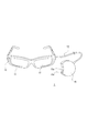
- the measuring device 1 suitable for such a way of thinking, for example, a form having a glass unit 11 as shown in FIG. 3 can be considered.
- the measuring device 1 is configured such that the glass unit 11 and the control unit 15 are connected by the cord 14.
- the glass unit 11 is of a spectacle type and can be worn by an operator like sunglasses during the grain-picking operation as shown in FIG.
- the control unit 15 has a small-sized housing, and the operator is stored in a pocket of clothes or the like.
- a camera 12 is mounted on the glass unit 11 so that the front of the worker can be photographed.
- the front of the glasses-type glass unit 11 is an on-glass display section 13.
- the on-glass display unit 13 is usually a transparent or semi-transparent liquid crystal panel or the like, and the user can see the front simply as a glass, but can perform a necessary display on the glass.
- FIG. 5 shows a state of display on the on-glass display portion 13 in a state where the user wears the glass unit 11 as shown in FIG. While the user can see the grapes 22, 23, 24 through the transparent plate serving as the on-glass display unit 13, a grain number display 25, such as the “grain number 45” shown in the figure, is performed, and is measured by this. You can check the number of grains.
- the on-glass display unit 13 may display the captured image of the camera 12 as a through image as it is, instead of being in a transparent or translucent state.
- the control unit 15 is provided with an operation button 15a, which enables, for example, power-on / off operation.
- the camera 12, the on-glass display unit 13, and the operation button 15a described above are one aspect of the imaging unit 2, the display unit 9, and the operation unit 6 in FIG. 1, respectively.
- the glass unit 11 and the control unit 15 thus configured function as the measuring device 1 by mounting the respective units having the configuration shown in FIG. 1, for example.
- the camera 12 as the imaging unit 2 the on-glass display unit 13 as an example of the display unit 9 are mounted on the glass unit 11, and the operation button 15a as an example of the operation unit 6 is mounted on the control unit 15.
- each part shown in FIG. 1 may be mounted on either the glass unit 11 or the control unit 15.
- a configuration in which all the configurations shown in FIG. 1 are provided in the glass unit 11 and the control unit 15 is not provided is also conceivable.
- the form of the measuring device 1 is not limited to the form of the glass unit 11 and the control unit 15 of FIG. 3, and other forms will be described later, but the form of FIG. 3 will be described below as an example. Go.
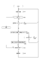
- FIG. 6 shows an example of processing executed by the control unit 5 by the functions of the measurement target identification unit 5a, the measurement unit 5b, and the presentation control unit 5c of FIG.
- the control unit 5 of the measuring device 1 executes the process of FIG. 6 while the power is turned on.
- step S101 the control unit 5 performs a waiting process.
- the standby process is a process of performing imaging by the imaging unit 2 and monitoring the analysis result of the captured image by the image analysis unit 4, the detection result by the sensor unit 7, and the operation by the operation unit 6. More specifically, the control unit 5 monitors whether or not an operation that means the end of measurement by the operation unit 6 has been performed.
- the operation which means the end of the measurement is, for example, an operation for stopping the measurement and performing various settings, an operation for shifting to another mode, a power-off operation, or the like. When such an operation is detected, the control unit 5 finishes the processing of FIG. 6 from step S102 and shifts to other necessary processing.
- control unit 5 also detects whether or not the operator's hand has entered the angle of view by the imaging unit 2. To put a hand in the angle of view means that the operator's hand is shown in the captured image captured by the image capturing unit 2.
- ⁇ Determine the presence of a hand within the angle of view by distinguishing the skin color by image analysis
- ⁇ Determining the human hand by temperature using the image captured by the thermotracer
- ⁇ To discriminate using the human hand discrimination method realized by machine learning and deep learning using the images captured by the TOF sensor and stereo camera
- ⁇ There is a method of distinguishing gloves with a specific color and pattern by the method of distinguishing gloves worn by the worker.
- a method for discriminating the gloves worn by the worker for example, a process in which the worker wears a glove with a checkered pattern as shown in FIG. 7 and the pattern is discriminated by image recognition is a process.
- the color of the gloves may be a color that is not in the farm (for example, purple) or the like, and it may be determined that the hand is within the angle of view by the color determination in the image.
- the control unit 5 monitors the timing of measurement execution. That is, the control unit 5 monitors in step S104 that the hand grips the branch of the bunch of grapes and further rotates the bunch in the gripped state.
- the following example can be considered as a means for determining that the hand has grabbed a branch.
- a pressure sensor is installed on the fingertips or gloves of the operator to determine that the branch has been grasped by the change in pressure.
- Thermotracer captures temperature changes due to blood flow changes in the fingers. In other words, it is detected by utilizing the fact that the blood flow is changed by grasping the branch.
- the control unit 5 detects that the hand of the operator whose hand is included in the captured image has once gripped the branch of the bunch of grapes, but has separated without rotating, or further the angle of view. If it is detected that it has also gone out of, the process returns from step S105 to S101.
- the control unit 5 When it is detected that the branch of the tuft is picked and rotated by the hand that has entered the angle of view, the control unit 5 automatically starts counting the number of grains starting from this. That is, the control unit 5 proceeds from step S104 to step S106, and executes the grain number measurement process for the tufts of the picked branches.
- To measure the number of grains capture images from multiple directions of the tuft by rotating the tuft and measure the number of grains that are three-dimensionally present, including the number of grains that are on the back side of the tuft. .
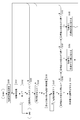
- step S106 The grain number measuring process in step S106 is shown in detail in FIG.
- step S120 of FIG. 8 the control unit 5 specifies the required number of captured images (N frames).
- N frames the required number of captured images
- the required number of frames during the period in which the worker is picking and rotating the branches of the tufts is the frame used for measurement.
- an operator can rotate the bunch of grapes by 120 to 150 degrees. This is because the branches do not usually break even if such an angle is turned.
- the frame image when rotated from about 120 degrees to about 150 degrees the grains originally on the back side also appear. Therefore, a plurality of frames in a period in which the worker rotates about 120 degrees to 150 degrees are extracted, and the number of particles is measured from there.
- the control unit 5 designates a required number (N) of frame image data among the frames of the captured image obtained at such a frame rate as a processing target.
- the N frames may be continuous frames or intermittently extracted frames, depending on the frame rate and the rotation speed. These may vary depending on the actual rotation period.
- step S122 the measurement object is specified for the nth frame specified.
- the process of specifying the measurement target object is performed for the first frame of the N frames designated as the processing target.
- the image analysis unit 4 is instructed to identify a bunch of grapes whose branches are picked by the operator's hand as a measurement target. That is, the bunch of grapes whose branches are picked by the operator's hand, which is recognized by the image analysis unit 4, is specified as the measurement target.
- a region (pixel region) as a tuft located below the operator's hand in the image is determined by image analysis, luminance edge detection, color determination, or the like.
- the pixel range of the grape tuft that is the measurement target is specified in the image of the frame that is the processing target.
- step S123 the control unit 5 (or the image analysis unit 4) measures the number of grape grains in the frame, and the control unit 5 obtains the measurement result. That is, the image of the grain is determined within the pixel range specified as the measurement target, and the number is measured.
- control unit 5 After measuring the number of particles in one frame, the control unit 5 confirms in step S124 whether or not the variable n has reached the designated frame number N, and if not, increments the variable n in step S125. It returns to step S122. Therefore, for the N frames selected as the processing target, the pixel range as the measurement target in the image is sequentially specified, and the number of particles in the pixel range is measured.
- the following example can be considered as a method for measuring the grains in the tufts at the tips of the grasped branches.
- ⁇ Measure the position of the hand with TOF and measure the number of grains in the same depth as that.
- ⁇ Measure the depth with a stereo camera or defocusing method, and then recognize each grain and measure the number of grains. Particles are detected and counted using a plurality of IR (infrared) lights having a wavelength absorbed by water and a wavelength not absorbed by water. In addition to IR, visible light or other wavelengths may be used. Grape grains contain more water than branches, and due to the difference in water content, a peak appears at a specific wavelength of infrared light corresponding to the grain. Therefore, it is possible to detect the portion of the grain having a large amount of water, which enables counting of the number of grains.
- IR infrared
- step S126 the control unit 5 sums the number of particles counted from each frame to calculate the number of particles in the entire bunch. That is, the measurement result of the number of grains in the specific grape bunch as the measurement target specified by the operator picking is obtained.
- step S107 the control unit 5 instructs the display control unit 8 to execute the grain number display 25 on the display unit 9 (for example, the on-glass display unit 13) as shown in FIG.
- the control unit 5 may generate and display not only the number of particles but also a predetermined determination result obtained from measurement.
- the measurement result may be presented not only by display but also by voice or vibration. After performing the processing for such presentation, the control unit 5 returns to the standby processing of step S101.
- the operator grasps the branch with the hand to specify the measurement target, and the measurement is executed by rotating the tuft.
- the object to be measured by the grasped branch even if a plurality of grapes 22, 23, 24 exist within the angle of view as shown in FIG. 5, for example, the grape 22 below the picked branch 22A. Only the tuft 22B is specified as the measurement object. This enables accurate measurement of each grape regardless of the reflection of the grape within the angle of view. Further, since it is not necessary to perform an extra operation such as pressing a shutter button for capturing an image, it does not hinder the granulation work. In addition, it is possible to accurately measure the number of particles by preventing the re-measurement of the particle initially measured from the image information of a plurality of frames and the information of the rotation angle of the tuft.
- FIG. 9 shows an example of processing executed by the control unit 5 by the functions of the measurement target identification unit 5a, the measurement unit 5b, and the presentation control unit 5c of FIG. It should be noted that, hereinafter, the same steps as those already described will be denoted by the same step numbers, and duplicate description will be avoided.
- the control unit 5 performs a standby process in step S101, monitors the end of the process in step S102, and monitors in step S103 whether or not the operator's hand is within the angle of view. In this example, if it is detected that the hand is within the angle of view, the control unit 5 proceeds to step S150 and determines whether the hand has picked a branch.
- step S101 when the hand appearing within the angle of view has not reached to pick the branch, the process returns to step S101, but when it is detected that the hand picks (grasps) the branch, the control unit 5 uses it as a measurement start trigger. Then, the process proceeds to step S106 to start the grain number measuring process. This process is performed, for example, as shown in FIG. In this case, the operator can accurately count the number of grains from the images of the plurality of frames by rotating the bunch of grapes.
- the control unit 5 proceeds from step S107 to step S108, and performs presentation control of the grain number as a measurement result.
- the process of FIG. 9 is an example in which it is determined that the hand has picked a branch and the measurement is started. It should be noted that in this example, the hand starts picking a branch to start the measurement, but it is possible that the worker does not rotate the tuft. Therefore, if the rotation of the tuft is not detected for a predetermined time or longer, the measurement may be ended in error. Alternatively, the measurement may be performed regardless of whether or not the tuft is rotated. For example, when it is detected that the grape has been rotated, the number of grains is measured in the process of FIG. 8 using images of a plurality of frames in which the cluster of grapes is viewed from different directions. On the other hand, when the image is not rotated, the images in each frame are almost the same.
- the number of grape grains is measured from the image of one frame (the image seen from one direction), and the coefficient is multiplied as in the fourth embodiment described later to estimate the number of grains on the back side (not shown in the image). The values are obtained, and the number of grains in the entire tuft is calculated from them.
- the measurement target object there may be an object or a feature amount that allows accurate measurement regardless of whether or not the measurement target object is rotated. In such a case, it is possible to start the measurement triggered by gripping the object, and appropriately specify the measurement target object based on the image from one direction or the sensing information to measure the feature amount.
- processing example of the third embodiment will be described with reference to FIG.
- the processing of FIG. 10 is also an example of processing executed by the control unit 5 by the functions of the measurement target identification unit 5a, the measurement unit 5b, and the presentation control unit 5c of FIG. 2. The difference from FIG. That is, the processing of steps S151 and S152 is performed in the state where it is detected.
- control unit 5 determines in step S150 that the hand has picked a branch, it does not immediately determine that the measurement has started, but in step S151 monitors whether a measurement start trigger is detected, and in step S152 Monitor whether or not they have left.
- the control unit 5 detects the trigger for starting the measurement based on the determination result from the image by the image analysis unit 4 and the detection information by the sensor unit 7.
- control unit 5 Even if the operator's hand once grips the branch of the bunch of grapes, the control unit 5 detects that the trigger has been released without being detected, or that the operator has also left the angle of view. If detected, the process returns from step S152 to S101.
- step S151 the control unit 5 proceeds from step S151 to step S106 and starts the grain number measuring process. This process is performed, for example, as shown in FIG. In this case, the operator can accurately count the number of grains from the images of the plurality of frames by rotating the bunch of grapes.
- step S107 the control unit 5 proceeds from step S107 to step S108, and performs presentation control of the grain number as a measurement result.
- a predetermined action as a trigger is assumed to be a vocal action of the worker, a sound action such as generating a predetermined sound, or a gesture action by the worker's hands or tools (scissors, etc.).
- ⁇ Speak with the branches picked by hand ⁇ Speak the prescribed words with the branches picked by hand.
- ⁇ Produce a predetermined sound with the branches picked by hand (sound of a tree, sound of scissors for grain selection, etc.).
- -Perform a predetermined gesture that can be recognized by the captured image with the branch picked by the hand (put the other hand in the angle of view, insert scissors in the angle of view, etc.).
- Performing a predetermined gesture that can be detected by the sensor unit 7 with the branch picked by the hand (striking the ground with a foot, shaking the other hand (detected by vibration or pressure), etc.).
- Grapes of grapes are three-dimensionally arranged around the branches, and the accurate number cannot be grasped only from the image taken from one direction. Therefore, in the first embodiment, a plurality of grapes are rotated when the cluster of grapes is rotated. It is assumed that measurement is performed from the frame image. However, measurement may be performed by imaging from one direction. In that case, it is conceivable to estimate and measure the number of grains in the tuft by calculating the product of the number of grains measured from an image in one direction and a predetermined coefficient value. Such an example is shown in FIG. 11 as a fourth embodiment.
- the control unit 5 performs the standby process in step S101 of FIG. 11, monitors the end of the process in step S102, and monitors whether the operator's hand is within the angle of view in step S103. Further, when it is detected that the hand has entered the angle of view, the control unit 5 proceeds to step S150 and determines whether the hand has picked a branch.
- step S101 when the hand appearing within the angle of view has not reached to pick the branch, the process returns to step S101, but when it is detected that the hand picks (grasps) the branch, the control unit 5 uses it as a trigger to start measurement. Then, the particle number measuring process from step S170 is executed.
- step S170 the control unit 5 designates an image of a certain imaged frame, and in step S171, performs a process of specifying a measurement object in the image.
- the image analysis unit 4 is instructed to identify a bunch of grapes whose branches are picked by the operator's hand as a measurement target.
- the image analysis unit 4 determines a region (pixel region), which is located under the operator's hand, as a tuft in the image of the one frame by image analysis, luminance edge detection, color determination, or the like, and the measurement target object is measured.
- the pixel range of the bunch of grapes is specified.
- step S172 the control unit 5 (or the image analysis unit 4) measures the number of grape grains within the pixel range of the measurement target, and the control unit 5 obtains the measurement result. That is, the image of the grain is determined within the pixel range specified as the measurement target, and the number is measured.
- step S173 the control unit 5 multiplies the acquired measurement result by a preset coefficient.
- the number of grains measured from the image is the number of grains on the front side that appear as the subject of the image capturing unit 2 when the image is captured.
- the coefficient is, for example, a coefficient for estimating the number of grains on the back side that are not shown in the captured image. Therefore, the number of grains on the back side is estimated by multiplying the measured number of grains by a coefficient.
- step S174 the control unit calculates the total number of grains in the tuft from the measured number of grains on the front side and the number of grains on the back side estimated by the coefficient multiplication. As a result, the measurement result of the bunch of grapes that is the measurement target is obtained. Then, in step S175, the control unit 5 performs a grain number presentation process. For example, the control unit 5 instructs the display control unit 8 to execute the grain number display 25 on the display unit 9 (for example, the on-glass display unit 13) as shown in FIG.
- the fifth embodiment has a function of setting a target value of the number of grains, and a function of notifying a worker of difference information with the target value and arrival of the target value.
- FIG. 12 shows a processing example of the fifth embodiment. 12 is an example of processing executed by the control unit 5 by the functions of the measurement target specifying unit 5a, the measuring unit 5b, the presentation control unit 5c, and the target setting unit 5d in FIG.
- step S100 the control unit 5 sets a target value for the number of grains.
- a target value is determined based on an input operation of a target number of particles by an operator, and the target value is stored in the storage unit 10.
- a target value such as “35 grains” is set.
- the control unit 5 performs a standby process in step S101, monitors the end of the process in step S102, and monitors in step S103 whether or not the operator's hand is within the angle of view. When detecting that the hand has entered the angle of view, the control unit 5 proceeds to step S150 and determines whether the hand has picked a branch.
- step S101 when the hand appearing within the angle of view has not reached to pick the branch, the process returns to step S101, but when it is detected that the hand picks (grasps) the branch, the control unit 5 uses it as a measurement start trigger. Then, the process proceeds to step S106 to start the grain number measuring process.
- This process is performed, for example, as shown in FIG. Also in this case, the operator can accurately measure the number of grains from the images of the plurality of frames by rotating the bunch of grapes, but the measurement algorithm may be switched depending on whether the operator rotates the grape cluster. For example, the measurement algorithm that uses a plurality of frames and the algorithm that uses one frame and the coefficient for estimating the backside grain number are switched depending on whether or not to rotate.
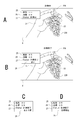
- the particle number display 25 the numerical value is not displayed because it is still being measured.
- the target display 26 the set target value (for example, “35”) is displayed. “Measuring” is displayed as the status display 27. By displaying in this way, the operator can clearly recognize the target value.
- step S180 the control unit 5 compares the number of particles obtained by the particle number measurement process with the stored target value, and determines whether the difference is 6 or more.
- step S181 the control unit 5 proceeds to step S181 and performs a process of presenting the number of particles and the like to the operator.
- the control unit 5 generates information such as the number of particles, the target value, the status, the situation, etc., transmits it to the display control unit 8, and causes the display unit 9 to display it.
- FIG. 13B shows a display example of the display unit 9.
- a measured value for example, “45” is displayed as the grain number display 25.
- the set target value for example, “35” is displayed.
- “Measurement completed” is displayed as the status display 27.
- the current status is displayed as the status display 28. In this case, since the number of grains is still large, "large” is displayed. By displaying in this way, the operator can clearly recognize the current number of grains, the target value, and the situation.
- control unit 5 returns to step S106 and performs the grain number measurement process again. That is, after the operator starts the grain selection work, the grain number measurement process is repeatedly executed.
- step S180 Every time the grain number measurement is completed, the processing from step S180 is performed. If it is determined in step S180 that the difference from the target value is not 6 or more (that is, 5 or less), the control unit 5 proceeds to step S182, and if the difference is 5, proceeds to step S184. In this case, the control unit 5 instructs the display control unit 8 to display, as a display for the worker, a display indicating that the target is five after. For example, the display of the content as shown in FIG. 13C is executed (in FIG. 13C and FIG. 13D, only the presentation content portion based on the measurement is shown).
- the measured value “40” is displayed as the grain number display 25
- the target value “35” is displayed as the target display 26
- “measurement completed” is displayed as the status display 27.
- a display such as "5 more” is executed as the status display 28.
- the process of the control unit 5 returns to step S106 to repeat the grain number measuring process.
- the display is made at the timing of the remaining five until the target, but of course the timing is various, and the display is made such as "3 more" at the timing of the remaining three. Good.
- step S182 when the differences are 4, 3, 2, and 1, respectively, it does not correspond to the determinations in steps S182 and S183, and thus the process returns to step S106 without any particular notification.
- the difference is determined to be 5 or less in step S180 as described above, the remaining number is displayed regardless of the number of differences, so that the remaining number is changed, for example, in a countdown display. You may go.
- the process of the control unit 5 proceeds from step S183 to S185, and the control unit 5 notifies the target arrival.
- the display control unit 8 is controlled as described above. For example, as shown in FIG. 13D on the display unit 9, the measurement value “35” is displayed as the grain number display 25, the target value “35” is displayed as the target display 26, the “measurement is completed” as the status display 27, and the “target number reached” as the status display 28. The display like this is executed. As a result, the granulation work for this tuft is completed, so that the process of the control unit 5 returns to the waiting process of step S101.
- the worker can accurately perform grain selection up to the target grain number.
- an appropriate graining operation can be performed without being required by a skilled person or depending on the physical condition.
- FIG. 14 shows an example in which the grain to be grained is designated as the grained portion display 30 for the guide.
- the grain to be grained is designated as the grained portion display 30 for the guide.
- an algorithm is provided that selects grains that are densely packed preferentially, and the grains to be thinned are selected according to the number of remaining grains and the density of the grains, and the selected grains are displayed by the grain-pulling position display 30.
- the particles to be cut off in this way, even an inexperienced operator can make the particles have a uniform density after the plucking.
- FIG. 15A is an example in which a measurement system is configured by the glass unit 11A and the information processing device 50.
- the information processing device 50 a mobile terminal such as a smartphone or a tablet is assumed.
- FIG. 15B is also an example in which a measurement system is configured by the glass unit 11A and the information processing device 50, but it is assumed that the information processing device 50 is a notebook type or desktop type personal computer.
- the following operation mode (M1) ( M10) is possible.
- various sensors as the sensor unit 7 may be mounted on both the glass unit 11A side and the information processing device 50 side.
- the mounting location may differ depending on the type of sensor.
- the detection information of various sensors may be acquired (detection or reception of detection information) on the side of the device that performs the specific processing of the measurement target or the measurement processing.
- (M1) An image is captured by the glass unit 11A and the image is transmitted to the information processing device 50.
- the information processing device 50 identifies the measurement target and performs measurement processing, and further presents the measurement result and the like.
- (M2) An image is captured by the glass unit 11A and the image is transmitted to the information processing device 50.
- the information processing device 50 specifies the measurement target and performs measurement processing, and transmits information such as the measurement result to the glass unit 11A.
- the measurement results and the like are presented on the glass unit 11A side.
- the glass unit 11A captures an image to specify the measurement target and perform measurement processing. Then, the information such as the measurement result is transmitted to the information processing device 50.
- the information processing device 50 presents measurement results and the like.
- (M4) An image is captured by the glass unit 11A to identify the measurement target, and the captured image and information indicating the identified measurement target are transmitted to the information processing device 50.
- the information processing device 50 performs measurement processing, and further presents measurement results and the like.
- (M5) An image is captured by the glass unit 11A to identify the measurement target, and the captured image and information indicating the identified measurement target are transmitted to the information processing device 50.
- the information processing device 50 performs a measurement process and transmits the measurement result to the glass unit 11A. The measurement results and the like are presented on the glass unit 11A side.
- the information processing device 50 captures an image and transmits the image to the glass unit 11A.
- the glass unit 11A identifies the measurement target and performs measurement processing, and further presents measurement results and the like.
- the information processing device 50 captures an image and transmits the image to the glass unit 11A.
- the glass unit 11A identifies the measurement target and performs measurement processing, and transmits information such as the measurement result to the information processing device 50.
- the information processing device 50 presents the measurement results and the like.
- An image is captured by the information processing device 50, the measurement target is specified and measurement processing is performed, and information such as the measurement result is transmitted to the glass unit 11A.
- the measurement results and the like are presented on the glass unit 11A side.
- the information processing device 50 captures an image, identifies the measurement target, and transmits the captured image and information indicating the identified measurement target to the glass unit 11A.
- the glass unit 11A performs measurement processing, and further presents measurement results and the like.
- the information processing device 50 captures an image, identifies the measurement target, and transmits the captured image and information indicating the identified measurement target to the glass unit 11A.
- the glass unit 11A performs measurement processing, and transmits the measurement result and the like to the information processing device 50.
- the information processing device 50 presents the measurement results and the like.
- the glass unit 11A and the information processing device 50 form a measurement system, and the glass unit 11A functions as a measurement terminal.
- the measurement terminal A configuration example as 1A can be considered as shown in FIG.
- the measurement terminal 1A includes an imaging unit 2, an image signal processing unit 3, a control unit 5, an operation unit 6, a sensor unit 7, a storage unit 10, and a communication unit 16. That is, the image analysis unit 4, the display control unit 8, and the display unit 9 in the configuration of FIG. 1 are not provided, but the communication unit 16 is provided.
- the image pickup unit 2, the image signal processing unit 3, the control unit 5, the operation unit 6, the sensor unit 7, and the storage unit 10 are the same as those described in FIG. However, in the case of the above (M1) mode, the control unit 5 may not have the functional configuration shown in FIG.
- the communication unit 16 performs wired or wireless data communication or network communication with an external device.
- the communication unit 16 is provided to communicate with the information processing device 50.
- a short-range wireless communication unit such as Bluetooth (registered trademark) can be considered.
- the communication unit 16 performs communication via various networks such as the Internet, home network, LAN (Local Area Network), etc., and transmits / receives various data to / from servers, terminals, etc. on the network. You may
- the glass unit 11A may have the configuration of FIG.
- the control unit 5 has the function of the presentation control unit 5c in the configuration of FIG. 16, and the display control unit 8 and the display unit 9 of FIG. 1 may be added.
- the control unit 5 has the functions of the measurement target specifying unit 5a and the measurement unit 5b in the configuration of FIG. 16, and the image analysis unit 4 may be provided.
- the control unit 5 has the function of the measurement target specifying unit 5a in the configuration of FIG. 16, and the image analysis unit 4 may be provided.
- control unit 5 In the operation mode of (M5), in the glass unit 11A, the control unit 5 has the functions of the measurement target specifying unit 5a and the presentation control unit 5c in the configuration of FIG. 16, and the image analysis unit 4, the display control unit 8, and the display unit. 9 may be provided.
- the control unit 5 In the operation mode (M6), in the glass unit 11A, the control unit 5 has the functions of the measurement target identification unit 5a and the measurement unit 5b in the configuration of FIG. 16, and the image analysis unit 4, the display control unit 8, and the display unit 9 are included. Should be added. The image pickup unit 2 and the image signal processing unit 3 are unnecessary. In the case of the operation mode (M7), in the glass unit 11A, the control unit 5 has the functions of the measurement target specifying unit 5a and the measuring unit 5b in the configuration of FIG. 16, and the image analysis unit 4 may be added. The image pickup unit 2 and the image signal processing unit 3 are unnecessary. In the case of the operation mode (M8), the glass unit 11A only needs to include the display controller 8 and the display 9 in the configuration of FIG.
- the control unit 5 has the function of the measurement unit 5b in the configuration of FIG. 16, and the image analysis unit 4, the display control unit 8, and the display unit 9 may be provided.
- the glass unit 11A may be configured such that the control unit 5 has the function of the measurement unit 5b and the image analysis unit 4 in the configuration of FIG.
- the hardware configuration of the information processing device 50 can be realized by a configuration as a computer device as shown in FIG. 17, for example.
- the CPU 171 executes various processes according to a program stored in the ROM 172 or a program loaded from the storage unit 178 to the RAM 173.
- the RAM 173 also appropriately stores data necessary for the CPU 171 to execute various processes.
- the CPU 171, the ROM 172, and the RAM 173 are connected to each other via a bus 174.
- An input / output interface 175 is also connected to the bus 174.
- the input / output interface 175 includes an input unit 176 including a keyboard, a mouse, a touch panel, a display including an LCD or an organic EL panel, an output unit 177 including a speaker, a storage unit 178 including a hard disk, a modem, and the like.
- a communication unit 179 composed of the above is connected.
- the communication unit 179 performs communication processing via a network such as the Internet, and performs communication with peripheral devices by wired / wireless communication, bus communication, or the like.
- the communication unit 179 is provided to communicate with the glass unit 11A, and in that case, it is an example such as a short-range wireless communication unit such as Bluetooth. Can be considered.
- a drive 180 is also connected to the input / output interface 175 as necessary, a removable medium 181 such as a magnetic disk, an optical disk, a magneto-optical disk, or a semiconductor memory is appropriately mounted, and a computer program read from them is It is installed in the storage unit 178 as needed.
- a removable medium 181 such as a magnetic disk, an optical disk, a magneto-optical disk, or a semiconductor memory is appropriately mounted, and a computer program read from them is It is installed in the storage unit 178 as needed.
- a sensor unit 184 may also be connected to the input / output interface 175. As the sensor unit 184, various sensors can be considered as in the sensor unit 7 of FIG.
- the information processing device 50 includes the image capturing unit 182 and the image signal processing unit 183 in order to capture an image, and the image signal processing unit 183 is connected to the input / output interface 175. .
- the imaging unit 182 and the image signal processing unit 183 are the same parts as the imaging unit 2 and the image signal processing unit 3 in FIG.
- the image pickup unit 182 and the image signal processing unit 183 are not necessary in the cases of the above (M6) to (M10). In other words, it does not have to be installed, or even if it is installed, it does not have to be used. However, it is possible that the image pickup unit 182 is used as a sensor.
- the configuration according to each operation mode is as follows.
- the information processing apparatus 50 may have the configuration of FIG. 17, and in particular, the CPU 171 is provided with the functions of the measurement target identification unit 5a, the measurement unit 5b, and the presentation control unit 5c.
- the CPU 171 may have the functions of the measurement target specifying unit 5a and the measuring unit 5b in the configuration of FIG.
- the CPU 171 may have the function of the presentation control unit 5c in the configuration of FIG.
- the CPU 171 may have the functions of the measurement unit 5b and the presentation control unit 5c in the configuration of FIG.
- the CPU 171 in the information processing device 50, the CPU 171 may have the function of the measurement unit 5b in the configuration of FIG.
- the information processing device 50 may have the configuration of FIG.
- the CPU 171 in the information processing device 50, the CPU 171 may have the function of the presentation control unit 5c in the configuration of FIG.
- the CPU 171 in the information processing device 50, the CPU 171 may have the functions of the measurement target specifying unit 5a and the measuring unit 5b in the configuration of FIG.
- the CPU 171 in the information processing device 50, the CPU 171 may have the function of the measurement target specifying unit 5a in the configuration of FIG.
- the CPU 171 in the information processing apparatus 50, the CPU 171 may have the functions of the measurement target specifying unit 5a and the presentation control unit 5c in the configuration of FIG.
- the CPU 171 may be provided with the functions of the measurement target identification unit 5a, the measurement unit 5b, and the presentation control unit 5c. Although not mentioned, it may have a function as the target setting unit 5d.
- the programs forming the software are installed from a network or a recording medium.
- This recording medium is composed of a removable medium 181 which is distributed in order to distribute the program to a user, and which includes a magnetic disk, an optical disk, a magneto-optical disk, a semiconductor memory, or the like on which the program is recorded.
- it is also configured by a ROM 172 in which a program is recorded and a hard disk included in the storage unit 178, which is distributed to the user in a state of being incorporated in the apparatus body in advance.
- the above is a configuration example in the case of a measurement system including the glass unit 11A and the information processing device 50 as shown in FIGS. 15A and 15B.
- This is a measurement terminal 1A as a wearable (body-wearable) unit It can be regarded as a system based on the device 50.
- the body-mounted unit is a unit that can be mounted on a person's body or clothes. In that sense, various body-mounted units are assumed in place of the glasses-shaped glass unit 11A. For example, head-mounted type, earphone type, wristband type, clothes type, clip type, pocket storage type, pendant type and the like are assumed.
- FIG. 15C illustrates a case where the information processing device 50 as a mobile terminal such as a smartphone is the measurement device 1 of the embodiment.
- the information processing device 50 has the same configuration as in FIG. 1, and the worker uses the information processing device 50 (smartphone) to image grapes.
- the measurement is performed by performing the processing as in the first to fourth embodiments, and the grain number display 25 as the measurement result is performed as shown in FIG. 18A.
- FIG. 18B both the captured image display 29 and the grain number display 25 as the measurement result may be displayed.
- FIG. 15D illustrates a case where the imaging system 60 and the information processing device 50 form a measurement system.
- the imaging device 60 is a normal video camera, and the information processing device 50 substantially functions as the measuring device 1. That is, the information processing device 50 performs the operation as the measuring device 1 (processing of the first to fourth embodiments) using the captured image transmitted by communication.
- the imaging device 60 and the information processing device 50 it is also conceivable to combine the imaging device 60 and the information processing device 50 to form a measurement system.
- FIG. 19 shows the configuration of a measurement system via network communication.
- FIG. 19A shows the glass unit 11A, the communication terminal 51, the network 52, and the cloud server 53.
- the network 52 includes the Internet, LAN, VPN (Virtual Private Network), intranet, extranet, satellite communication network, CATV (Community Antenna Tele Vision) communication network, telephone line network, mobile communication network, and the like. The form is assumed.
- the cloud server 53 is composed of an information processing device.
- the cloud server 53 and the communication terminal 51 can be realized as a computer device as shown in FIG. 17, for example.
- the glass unit 11A transmits a captured image and sensor information to the communication terminal 51.
- the communication terminal 51 is, for example, a smartphone, a tablet, a dedicated terminal, or the like, and is an information processing device capable of network connection.
- the captured image, sensor information, and the like from the glass unit 11A are transmitted from the communication terminal 51 to the cloud server 53 via the network 52.
- the cloud server 53 has the functions of the measurement target specifying unit 5a and the measuring unit 5b to measure the number of particles and return the measurement result.
- the glass unit 11A displays the measurement result by receiving the measurement result via the network 52 and the communication terminal 51. In this way, it is also possible to build a measurement system using a so-called cloud service.
- FIG. 19B shows an AI engine 54 added to the configuration of FIG. 19A.
- the AI engine 54 performs measurement target identification processing and measurement processing based on image analysis. This makes it possible to perform highly accurate measurement processing, determination of measurement execution, and the like.
- the glass unit 11A which is a body-worn unit, may directly communicate with the network so that the communication terminal 51 is unnecessary.
- the measuring apparatus 1 includes a measurement target specifying unit 5a that performs a process of specifying a measurement target based on detection of gripping a grape branch (object) by an operator's hand (gripping body), and a measurement target specifying.
- the measuring unit 5b includes a measurement unit 5b that obtains a measurement result by the measurement process of the characteristic amount of the measurement target specified by the unit 5a. That is, in the embodiment, the measurement target is specified by detecting the action of grasping the branch by the gripping body such as the hand of the operator.
- the bunch of grapes is specified as the measurement target, and the characteristic amount, for example, the number of grains is measured.
- the measurement object can be clearly specified in the process of work in which an opportunity to grip the object occurs.
- the range to be measured becomes clear in the captured image.
- the act of gripping a branch with a hand is a part of the work to be performed (eg, grain selection) or an action leading to the work, it is possible to accurately specify the measurement target object in the natural flow of the work. become. As a result, it is possible to correctly set and measure the measurement target object for providing the worker with necessary information without requiring the worker to perform some extra action or operation.
- the usability is improved, the efficiency of the granulation work is improved, and the measurement accuracy is also improved.
- many bunches of grapes are included in the captured image.
- the process may become unstable in terms of which part of the image to measure the number of particles, but in the present embodiment, the measurement is performed by pinching a branch in the process of work. Since the power cell is specified, the number of particles in the cell desired by the worker can be correctly set as the measurement object in the process in which the worker performs normal work. Particularly in the case of agricultural crops in which fruits such as grapes and bananas form a tuft, it is very useful that the tuft to be measured is specified by gripping.
- grapes are given as an example, but the present technology is applicable to measurement of various objects such as crops such as bananas and tomatoes, natural objects such as trees and animals, and industrial products. Applicable.
- the measurement target is all or part of the objects specified by gripping among these various objects.
- the feature quantity is the number of grains, but in addition to the quantity, size (size), color, ingredient content, ingredient ratio, sugar content, water content, estimated price, etc. can be quantified and compared and evaluated. Therefore, the present technology can be widely applied to those measuring devices.
- the measurement apparatus 1 includes a presentation control unit 5c that performs processing for presentation based on the measurement result. This allows the operator to know information such as the number of grains in a bunch of grapes that holds the branches. That is, the measuring device 1 can provide appropriate information during the work process of the worker.
- the presentation based on the measurement result is not limited to the value of the measurement result itself of the feature amount, but may be appropriateness determination information or guide information according to the measurement result. For example, instead of the numerical value as the measurement result, the judgment information such as “appropriate”, “impossible”, “appropriate number”, “insufficient”, “excessive”, or by showing the guide content for the subsequent work, Precise work support is possible.
- the presentation device is not limited to the display unit 9 and includes a voice output unit, a vibration unit, and the like, the presentation control unit 5c presents the measured feature amount in a presentation mode according to these presentation devices. It may be controlled to be performed.
- the example in which the measurement process is performed using the captured image has been described.
- a captured image obtained by capturing an object by the integrated or separate imaging unit 2 is input.
- the feature amount that can be determined from the image is measured.
- a feature amount such as the number of grape grains.
- stable measurement is possible and the measurement accuracy can be improved. Note that not only the captured image but also the detection information from the sensor unit 7 can be used for measurement.
- the example in which the measurement process is executed based on the detection that the gripping body grips the object has been described (see FIGS. 9 and 11). That is, when the grasping of the object by the grasping body is detected, the measurement of the feature amount of the measurement object is started.
- the measurement target is specified based on the grip
- the worker does not perform a special operation (operation for instructing the start of measurement)
- the required measurement will be performed.
- the operation of pinching the branches of the tuft is an operation in the normal flow of work, so that the operator can perform the measurement at an appropriate timing without being aware of the measurement operation at all. Therefore, usability is greatly improved.
- gripping can also provide an appropriate measurement start timing depending on the object to be measured and the characteristic amount to be measured.
- the measurement process is executed based on the detection that the object is held by the holding body and the object is moved (see FIG. 8).
- the measurement of the feature amount of the measurement target is started when some movement is applied to the object while being gripped.
- the movement is supposed to be shaken, pinched and moved up and down, left and right, back and forth, shaken, and rotated.
- the measurement of the measurement target may require movement of the measurement target.
- movement for example, rotation of the tuft in addition to gripping may be a natural operation during work.
- the measurement is performed when the pinching operation and the movement are detected, so that the measurement is appropriately performed when necessary. Further, since no special operation (operation for instructing the start of measurement) of the worker is required, the operation load does not occur. Furthermore, moving an object in a grasped state (for example, moving it up and down, left and right, front and back, rocking, and rotating in a pinched state) can be positioned as a conscious measurement start operation by an operator. it can. In that case, it is possible to instruct the apparatus to start measurement as a simple operation that continues from gripping. For example, it is suitable when it is desired to execute the measurement not only by picking but also by some kind of trigger.
- the example in which the measurement process is performed based on the detection of a predetermined action other than the gripping of the object by the gripping body has been described.
- a predetermined action is assumed to be a voice action of the worker, a sound action such as generating a predetermined sound, and a gesture action using a tool (scissors, etc.) held by the worker.
- Performing a predetermined action by the worker in the gripped state is an operation for starting measurement. This allows the operator to instruct the apparatus to start measurement at an appropriate timing in the gripped state.
- a predetermined action other than the gripping body by performing a predetermined action other than the gripping body, it is possible to easily give an instruction in a gripped state (picking grape branches). Specifically, if the operator's utterance, the operator's predetermined words are uttered, or sound is generated (the other hand of the picked hand or something held in the hand to generate some sound), There is no hindrance. In addition, for example, putting the other hand into the image and making a predetermined gesture with the hand picking the branch, putting the scissors held by the other hand in the angle of view of the imaging unit 2, making a predetermined gesture, etc. Also, in this case, the operation will not be a burden during the work.
- the example in which the measurement process is performed using the images of the plurality of frames captured during the period in which the measurement target object is moved has been described (see FIG. 8).
- a captured image obtained by capturing an object by the image capturing unit 2 is input, but measurement is performed using a plurality of frames of an image obtained as a moving image.
- the feature amount can be accurately detected even when there is a front surface and a back surface.
- both the grain on the front side and the grain on the back side can be measured from the image captured while rotating. This can improve the measurement accuracy.
- the measurement target specifying unit 5a has described the example in which the object held by the gripping body and moved is used as the measurement target (see FIG. 6).
- an object or a part of the object to which some movement is applied in the gripped state is set as the measurement object.
- the movement includes being pinched and moved up and down, left and right, back and forth, shaken, and rotated.
- the target setting unit 5d that sets the target value of the feature amount is provided, and the target setting unit 5d is configured to obtain the difference value between the feature amount and the target value measured in the measurement process (see FIG. 12). ).
- the target value of the feature amount is set and stored by user setting or automatic setting so that it can be compared with the measured value. For example, when setting the number of particles as a target value during the granulating work, by comparing this with the measured number of particles, it is possible to obtain difference information indicating how much more particles should be granulated.
- the presentation control unit 5c that performs processing for presenting the difference value between the feature amount measured in the measurement processing and the target value is provided (see FIGS. 12 and 13).
- the presentation control unit 5c presents the difference between the current feature amount and the target value by a method such as display or voice.
- a method such as display or voice.
- an example in which the movement as the trigger of the measurement process is the rotational movement of the bunch of grapes is given (see FIG. 6).
- the rotational movement of the bunch of grapes is given (see FIG. 6).
- detection of rotational movement may be used to specify the measurement target.
- the object to be measured can be more accurately specified as a rotating tuft.
- the human hand is used as the gripping body for gripping to specify the measurement target, but an instrument operated by a human or a robot arm that automatically operates may be used.
- the human hand includes a bare hand and a gloved hand.
- the gripping body may be an instrument, but the instrument means a person's intention in any form, such as an instrument operated manually by a person, an instrument operated by a person other than the hand, an instrument attached to the hand, and an instrument operated remotely. Indicates any device that can be gripped with.
- the opposite hand has scissors during the grain picking operation, it may be possible to detect gripping by the scissors.
- various tools may be used in the work.
- As a measuring device for work using a tool it is effective to detect gripping by the tool and specify a measurement target.
- it may be useful to detect grasping by a robot arm used for factory automation or the like for specifying a measurement target.
- a robot arm By specifying the measurement object by gripping with a robot arm, such as when cultivating agricultural products, working processes during shipment, measurement on distribution lines, measurement on processed food production lines, etc., measurement on industrial product production lines, etc. It is assumed that accurate measurement is possible.
- a human hand, an instrument, or a robot arm is assumed as the grasping body, that is, if it can be grasped, an object grasped by the grasping object can be an object to be measured.
- an object grasped by the grasping object can be an object to be measured.
- the object to be measured is grape, that is, an agricultural crop.
- the measurement target specifying unit specifies an individual of the gripped agricultural product among the agricultural products as a measurement target.
- Agricultural crops are broadly defined agricultural crops and include fruits, vegetables, grains, trees, flowers, mushrooms, fertilizers, feeds, horticultural crops, industrial crops, and the like. According to the technique of the embodiment, it is possible to widely provide the measuring device 1 for such various agricultural crops.
- the measurement target specifying unit 5a performs a process in which a bunch of grapes whose branches are gripped by the gripping body is set as a measurement target, and in the measurement process, as a feature amount of the bunch of grapes set as the measurement target.
- An example of measuring the number of particles is given. That is, the bunch of grapes from which the branches have been plucked is set as the measurement target, and the number of grains in the bunch is measured. For each bunch of grapes present in the plantation, the branches are picked to identify the bunch to be measured, and the number of grains is measured. As a result, it is possible to accurately measure the number of grains for each tuft, and it is possible to accurately provide the operator with the number of grains information necessary for the grape plucking operation.
- the measuring apparatus 1 includes the image capturing unit 2 that captures an image used for the measurement process.
- the measuring unit 5b analyzes the image picked up by the image pickup unit 2 to measure the number of particles. Since the image pickup unit 2 is provided in the measuring device 1, a separate image pickup device may be prepared or installed. It is not necessary to do so, and it is possible to provide a measuring device having good usability in the process of granulation and the like. 1 and 3, the example in which the imaging unit 2 (camera 12) is built in is described, but the imaging unit 2 may be provided as a separate device.
- the imaging unit (camera 12) that captures an image used for the measurement process and the presentation unit (on-glass display unit 13) that presents the measurement result are provided.
- the worker can simply attach the body-mounted unit to the equipment for imaging the measurement target and displaying the measurement result. You don't have to care.
- the glasses unit 11 is equipped with the camera 12 and the glass unit 11 including the on-glass display unit 13, it is possible to perform the work without worrying about the device arrangement and the shooting direction. You can check the number of grains accurately.
- the presentation unit refers to a unit capable of presenting the measurement result to the user, for example, a display unit, a voice output unit, a vibration unit, or the like, which can present some information to the user's five senses. It is naturally conceivable that a speaker and an amplifier circuit as an audio output unit, an actuator as a vibrating unit, and the like are provided in a body-mounted unit such as the glass unit 11.
- the on-glass display unit 13 in which information is displayed on the display surface arranged in front of the user is taken as an example of the presentation unit. This allows the operator to confirm the measurement result in the field of view for work. In other words, the measurement information can be viewed naturally in the work process without having to pay attention to the measurement results one by one, which is very suitable in terms of work efficiency.
- the embodiment has described the example in which the sensor unit 7 that detects the grip of the object by the grip body is provided.
- a gripping body such as a human hand, an instrument, or a robot arm
- an imaging device that detects an image, pressure, temperature information, distance measurement information, a pressure sensor, a thermotracer, a measuring unit, or the like.
- Distance sensors and the like are assumed. Based on the information obtained by the sensor unit 7 or the image pickup unit 2, it is possible to detect gripping of an object by a gripping body such as a human hand, an instrument, or a robot arm, thereby identifying the measurement target and determining the measurement start timing. Can be executed properly.
- the measuring device 1 of the embodiment may have the following configuration. Since the image pickup unit 2 may be backlit depending on the work posture during the grain picking work, it is desirable that the image sensor in the image pickup unit 2 has a dynamic range of ISO 10000 or more. Further, the image pickup unit 2 may be provided with an automatic exposure function (Automatic Exposure) and a function capable of automatically switching a neutral density filter (such as a liquid crystal variable ND filter). The measurement accuracy can be improved by using the image captured by the image capturing unit 2.
- Auto Exposure Automatic Exposure
- a neutral density filter such as a liquid crystal variable ND filter
- the measuring device 1 since it is assumed that the measurement device 1 is operated in the rain, it is desirable that the measuring device 1 has a waterproof structure.
- the front lens or the cover glass of the image pickup unit 2 may be subjected to water repellent treatment.
- the object to be grasped shakes and the crop shakes and the image blurs
- the measuring device 1 vibrates, its movement is detected by a gyro sensor (angular velocity sensor), an acceleration sensor, or the like, and pixels are electronically moved according to the detected amount to correct blur, or a lens or It may have means for mechanically moving the image sensor or the camera module to correct the blur.
- the measuring device 1 may measure the sugar content, the estimated price at shipping, the number of grains per unit area, and the number of grains to be thinned, and notify the worker.
- the feature amount is not limited to the number of grains. It is also possible to set an appropriate number of grains for each tuft or each area in the farm and to provide work support such as notifying the workers.
- the locus of movement of the measuring device 1 is detected by a gyro sensor, an acceleration sensor, a GPS receiver, a geomagnetic sensor, and the like, and the feature amounts obtained by the measuring device 1 are associated and mapped to improve the efficiency of farm management. It is also possible to consider
- the number of grains in each bunch is measured while automatically moving in the farm, and the grain is plucked, or the number of grains is measured at night, and the operator the next morning, how many grains are bunched. It is also effective to use a system that tells you what to do or what to do.
- the measurement start timing and the measurement result may be transmitted to the operator by voice or video.
- the measurement start timing is notified by electronic sound or the like. This allows the user to understand the measurement operation of the measuring device 1.
- the measuring device 1 may be provided with a part as a microcomputer or a processor for performing these processes, and it may be a part as a control part, a part as an image analysis part, or another part.
- the program according to the embodiment is a program that causes, for example, a CPU, a DSP, or the like, or a device including these to execute the processes of FIGS. 6, 8, 9, 10, 11, and 12. That is, the program of the embodiment includes an information processing apparatus that performs a process of specifying a measurement target object based on detection of gripping of an object by a gripping body, and a process of obtaining a measurement result by a measurement process of a feature amount of the specified measurement target object. It is a program to be executed by.
- the measuring device 1 and the information processing device 50 described above can be realized by such a program.
- Such a program can be recorded in advance in an HDD as a recording medium built in a device such as a computer or a ROM in a microcomputer having a CPU.
- a flexible disc a CD-ROM (Compact Disc Read Only Memory), an MO (Magnet optical) disc, a DVD (Digital Versatile Disc), a Blu-ray disc (Blu-ray Disc (registered trademark)), a magnetic disc, a semiconductor memory
- a removable recording medium such as a memory card.
- Such a removable recording medium can be provided as so-called package software.
- such a program can be installed from a removable recording medium into a personal computer or the like, or can be downloaded from a download site via a network such as a LAN (Local Area Network) or the Internet.
- LAN Local Area Network
- Such a program is suitable for providing a wide range of the information processing apparatus 50 of the embodiment.
- a program is suitable for providing a wide range of the information processing apparatus 50 of the embodiment.
- a personal computer a portable information processing device, a mobile phone, a game device, a video device, a PDA (Personal Digital Assistant) or the like, the personal computer or the like is used as the measuring device 1 or the measuring system of the present disclosure.
- the information processing apparatus 50 can function.
- a measurement target specifying unit that performs a process of specifying a measurement target based on detection of gripping of an object by a gripping body
- a measuring device comprising: a measuring unit that obtains a measurement result by a measurement process of the characteristic amount of the measurement target specified by the measurement target specifying unit.
- the measurement device according to (1) further including a presentation control unit that performs a process for presentation based on the measurement result.
- the measurement process is The measuring device according to any one of (1) to (3), which is executed based on detection that an object is gripped by the grip body.
- the measurement process is The measuring device according to any one of (1) to (3), wherein an object is gripped by the gripping body and is executed based on detection that the object is moved.
- the measurement process is The measuring device according to any one of (1) to (3) above, wherein an object is gripped by the grip body and is executed based on detection of a predetermined action other than the grip.
- the measurement device according to any one of (1) to (6), wherein the measurement process is performed using images of a plurality of frames captured during a period in which the measurement target is moving.
- the measurement target specifying unit The measuring device according to any one of (1) to (7) above, which performs a process in which an object that is gripped by the gripper and that is moved is used as a measurement target.
- the said target setting part is a measuring device in any one of said (1) to (8) which calculates
- the object to be measured is an agricultural product.
- the measurement target specifying unit performs a process of setting a bunch of grapes whose branches are gripped by the gripping body as a measurement target, In the measurement process, the measurement device according to any one of (1) to (13), wherein the number of grains is measured as a feature amount of a bunch of grapes that is a measurement target.
- the measurement device wherein the presentation unit is a display unit for displaying information on a display surface arranged in front of the user's eyes.
- the measuring device according to any one of (1) to (17), further including a sensor unit that detects gripping of an object by the gripping body.
- (21) A process of specifying a bunch of grapes to be measured based on detection of gripping a bunch of grapes by a gripping body, A process of starting the measurement of the number of grains of the identified grape bunch; A measurement method that an information processing device performs.
- 1 measurement device 1A measurement terminal, 2 imaging unit, 3 image signal processing unit, 4 image analysis unit, 5 control unit, 5a measurement target specifying unit, 5b measurement unit, 5c presentation control unit, 5d target setting unit, 6 operation unit , 7, sensor unit, 8 display control unit, 9 display unit, 10 storage unit, 11 glass unit, 12 camera, 13 on-glass display unit, 14 code, 15 control unit, 16 communication unit, 21 hand, 22, 23, 24 Grape, 22A branch, 22B bunch, 25 grain number display, 26 target display, 27 status display, 28 status display, 29 captured image display, 30 grain selection point display, 50 information processing device, 51 communication terminal, 52 network, 53 cloud server , 54 AI engine, 60 imaging device
Landscapes
- Physics & Mathematics (AREA)
- Life Sciences & Earth Sciences (AREA)
- Spectroscopy & Molecular Physics (AREA)
- General Physics & Mathematics (AREA)
- Health & Medical Sciences (AREA)
- Chemical & Material Sciences (AREA)
- Engineering & Computer Science (AREA)
- Pathology (AREA)
- Biochemistry (AREA)
- General Health & Medical Sciences (AREA)
- Analytical Chemistry (AREA)
- Immunology (AREA)
- Food Science & Technology (AREA)
- Environmental Sciences (AREA)
- Medicinal Chemistry (AREA)
- Forests & Forestry (AREA)
- Ecology (AREA)
- Biodiversity & Conservation Biology (AREA)
- Robotics (AREA)
- Computer Vision & Pattern Recognition (AREA)
- Theoretical Computer Science (AREA)
- Image Analysis (AREA)
- Investigating Or Analysing Materials By Optical Means (AREA)
- Image Processing (AREA)
Abstract
計測装置又は計測方法として、把持体によるブドウの房の把持の検出に基づいて計測対象となるブドウの房を特定する処理と、特定されたブドウの房の粒数の計測を開始する処理と、を情報処理装置が行うようにする。
Description
本技術は計測装置、計測方法、プログラムに関し、特に各種の作業過程において計測対象物の特徴量の計測に用いることができる技術に関する。
物体の計測に関しては各種の技術が知られている。
例えば下記特許文献には、ベルトコンベア上に流れる米粒に対してリニアイメージセンサによる走査を行い、品位判定を行う技術が開示されている。
例えば下記特許文献には、ベルトコンベア上に流れる米粒に対してリニアイメージセンサによる走査を行い、品位判定を行う技術が開示されている。
例えば計測対象とした物体に関する数やサイズなどを計測する場合を考えると、まず計測対象物を特定することが重要である。
ところが計測対象の特定のためだけに作業者に何らかの余分な行為を課することは好ましくない。
そこで本技術は、計測装置による計測を伴う作業過程でユーザ(作業者)に余分な行為負担や操作負担を求めずに、適切に計測対象を特定できるようにすることを目的とする。
ところが計測対象の特定のためだけに作業者に何らかの余分な行為を課することは好ましくない。
そこで本技術は、計測装置による計測を伴う作業過程でユーザ(作業者)に余分な行為負担や操作負担を求めずに、適切に計測対象を特定できるようにすることを目的とする。
本技術に係る計測装置は、把持体による物体の把持の検出に基づいて計測対象物を特定する処理を行う計測対象特定部と、前記計測対象特定部が特定した計測対象物の特徴量の計測処理による計測結果を得る計測部とを備える。
把持体とは、例えば作業者の手や指、手袋や所定器具を装着した状態の作業者の手や指、人の操作により物体を把持することのできる器具、自動的に物体を把持できる器具、ロボットアームなど、物体を把持することのできるものをいう。
物体とは、ブドウ、バナナ、トマト等の農作物、樹木や動物等の自然物、工業製品など各種の物体を指し、計測対象物は、これらの物体のうちで、把持によって特定される物体の全部又は一部となる。
特徴量とは、個数、大きさ(サイズ)、色、成分含有量、成分比率、糖度、含水率、推定価格等など、数値化したり比較評価できるものを指す。
把持体とは、例えば作業者の手や指、手袋や所定器具を装着した状態の作業者の手や指、人の操作により物体を把持することのできる器具、自動的に物体を把持できる器具、ロボットアームなど、物体を把持することのできるものをいう。
物体とは、ブドウ、バナナ、トマト等の農作物、樹木や動物等の自然物、工業製品など各種の物体を指し、計測対象物は、これらの物体のうちで、把持によって特定される物体の全部又は一部となる。
特徴量とは、個数、大きさ(サイズ)、色、成分含有量、成分比率、糖度、含水率、推定価格等など、数値化したり比較評価できるものを指す。
上記した本技術に係る計測装置においては、前記計測結果に基づく提示のための処理を行う提示制御部を備えることが考えられる。
即ち提示制御部は、計測部によって計測した特徴量や、特徴量に基づく情報を、表示、音声、振動等により提示を実行させるようにするための制御を行う。例えば計測情報やそれに基づく判定情報等を提示させる処理を行う。
即ち提示制御部は、計測部によって計測した特徴量や、特徴量に基づく情報を、表示、音声、振動等により提示を実行させるようにするための制御を行う。例えば計測情報やそれに基づく判定情報等を提示させる処理を行う。
上記した本技術に係る計測装置においては、前記計測処理は、撮像された画像を用いて行われることが考えられる。
例えば一体又は別体の撮像装置により物体を撮像した撮像画像を入力する。この撮像画像を用いて画像から判定できる特徴量の計測を行う。
例えば一体又は別体の撮像装置により物体を撮像した撮像画像を入力する。この撮像画像を用いて画像から判定できる特徴量の計測を行う。
上記した本技術に係る計測装置においては、前記計測処理は、前記把持体による物体の把持が行われたことの検出に基づいて実行されるようにすることが考えられる。
即ち把持体による物体の把持が検出されたことにより、計測対象物の特徴量の計測を開始する。
即ち把持体による物体の把持が検出されたことにより、計測対象物の特徴量の計測を開始する。
上記した本技術に係る計測装置においては、前記計測処理は、前記把持体により物体の把持が行われ、かつ物体が移動させられたことの検出に基づいて実行されるようにすることが考えられる。
例えば把持された状態で物体に何らかの動きが加えられたことで計測対象物の特徴量の計測を開始する。移動とは、揺らされたり、つままれて上下左右前後に移動されたり、回転されたりすることなどが想定される。
例えば把持された状態で物体に何らかの動きが加えられたことで計測対象物の特徴量の計測を開始する。移動とは、揺らされたり、つままれて上下左右前後に移動されたり、回転されたりすることなどが想定される。
上記した本技術に係る計測装置においては、前記計測処理は、前記把持体により物体の把持が行われ、かつ当該把持以外の所定行為の検出に基づいて実行されるようにすることが考えられる。
例えば把持体が物体を把持した状態で、所定行為が行われることを検知して計測対象物の特徴量の計測を開始する。所定行為とは、作業者の発声や、所定音を発生させるなどの音的な行為、作業者の手や用具(ハサミ等)によるジェスチャ的な行為などが想定される。
例えば把持体が物体を把持した状態で、所定行為が行われることを検知して計測対象物の特徴量の計測を開始する。所定行為とは、作業者の発声や、所定音を発生させるなどの音的な行為、作業者の手や用具(ハサミ等)によるジェスチャ的な行為などが想定される。
上記した本技術に係る計測装置においては、前記計測処理は、計測対象物が移動されている期間に撮像された複数のフレームの画像を用いて行われることが考えられる。
例えば一体又は別体の撮像装置により物体を撮像した撮像画像を入力するが、例えば動画として得られる画像の複数フレームを用いて計測を行う。
例えば一体又は別体の撮像装置により物体を撮像した撮像画像を入力するが、例えば動画として得られる画像の複数フレームを用いて計測を行う。
上記した本技術に係る計測装置においては、前記計測対象特定部は、前記把持体により把持が行われ、かつ移動させられた物体を計測対象物とすることが考えられる。
例えば把持された状態で何らかの動きが加えられた物体又は物体の一部を計測対象物とする。移動とは、つままれて上下左右前後に移動されたり、揺らされたり、回転されたりすることなどが想定される。
例えば把持された状態で何らかの動きが加えられた物体又は物体の一部を計測対象物とする。移動とは、つままれて上下左右前後に移動されたり、揺らされたり、回転されたりすることなどが想定される。
上記した本技術に係る計測装置においては、特徴量の目標値を設定する目標設定部を有し、前記目標設定部は、前記計測処理で計測される特徴量と前記目標値の差分値を求めることが考えられる。
例えばユーザ設定や自動設定などにより、特徴量の目標値を設定して記憶しておき、計測値と比較できるようにする。
例えばユーザ設定や自動設定などにより、特徴量の目標値を設定して記憶しておき、計測値と比較できるようにする。
上記した本技術に係る計測装置においては、前記差分値を提示するための処理を行う提示制御部を備えることが考えられる。
提示制御部により、表示や音声などの手法で、現状の特徴量と目標値の差分を提示する。
提示制御部により、表示や音声などの手法で、現状の特徴量と目標値の差分を提示する。
上記した本技術に係る計測装置においては、前記移動は回転移動であることが考えられる。
例えば把持された状態で物体が回転されることを検知して計測を開始する。
例えば把持された状態で物体が回転されることを検知して計測を開始する。
上記した本技術に係る計測装置においては、前記把持体は、人の手、人により操作される器具、又は自動動作するロボットアームのいずれかであることが考えられる。
計測対象特定部は、把持体としての人の手、器具、ロボットアームのいずれかによる把持を検出して計測対象物を特定する。人の手とは、素手、手袋等をした手を含む。器具とは人が手で操作する器具、手以外で操作する器具、手に装着して用いる器具、遠隔操作する器具など、どのような態様であれ人の意思で把持が可能なあらゆる器具を指す。ロボットアームは自動制御により把持が可能なものを指す。
計測対象特定部は、把持体としての人の手、器具、ロボットアームのいずれかによる把持を検出して計測対象物を特定する。人の手とは、素手、手袋等をした手を含む。器具とは人が手で操作する器具、手以外で操作する器具、手に装着して用いる器具、遠隔操作する器具など、どのような態様であれ人の意思で把持が可能なあらゆる器具を指す。ロボットアームは自動制御により把持が可能なものを指す。
上記した本技術に係る計測装置においては、計測対象物とされる物体は農作物であることが考えられる。
即ち計測対象特定部は、農作物のうちで、把持された農作物の個体を計測対象物と特定する。ここでいう農作物とは広義の農作物で、果物、野菜、穀物、樹木、草花、キノコ類、肥料、飼料、園芸作物、工芸作物、などを含む。
即ち計測対象特定部は、農作物のうちで、把持された農作物の個体を計測対象物と特定する。ここでいう農作物とは広義の農作物で、果物、野菜、穀物、樹木、草花、キノコ類、肥料、飼料、園芸作物、工芸作物、などを含む。
上記した本技術に係る計測装置においては、前記計測対象特定部は、前記把持体によって枝が把持されたブドウの房を計測対象物とする処理を行い、前記計測処理では、計測対象物とされたブドウの房の特徴量として粒数を計測することが考えられる。
枝が摘まれたブドウの房を計測対象物とし、その房の粒数の計測を行うようにする。
枝が摘まれたブドウの房を計測対象物とし、その房の粒数の計測を行うようにする。
上記した本技術に係る計測装置においては、前記計測処理に用いる画像の撮像を行う撮像部を備えることが考えられる。
例えば一体又は別体の撮像部を備えるようにする。
例えば一体又は別体の撮像部を備えるようにする。
上記した本技術に係る計測装置においては、前記計測処理に用いる画像の撮像を行う撮像部と、前記計測結果の提示を行う提示部と、を有し、前記撮像部と前記提示部が身体装着型ユニットに配置されていることが考えられる。
身体装着型ユニットとは、人の身体や衣服に装着できるユニットであり、例えばヘッドマウント型、眼鏡型、イヤホン型、リストバンド型、衣服型、クリップ型、ポケット収納型、ペンダント型などの形態が想定される。このような身体装着型ユニットに撮像部と提示部が配置される。
提示部とは、ユーザに計測結果を提示できるもので、例えば表示部、音声出力部、振動部など、ユーザの五感に対して何らかの情報提示ができるものを指す。
身体装着型ユニットとは、人の身体や衣服に装着できるユニットであり、例えばヘッドマウント型、眼鏡型、イヤホン型、リストバンド型、衣服型、クリップ型、ポケット収納型、ペンダント型などの形態が想定される。このような身体装着型ユニットに撮像部と提示部が配置される。
提示部とは、ユーザに計測結果を提示できるもので、例えば表示部、音声出力部、振動部など、ユーザの五感に対して何らかの情報提示ができるものを指す。
上記した本技術に係る計測装置においては、前記提示部は、ユーザの眼前に配置される表示面に情報表示が行われる表示部とされることが考えられる。
例えばヘッドマウント型、眼鏡型などとされて、使用者の眼前に配置される表示部に、計測結果等の情報が表示されるようにする。
例えばヘッドマウント型、眼鏡型などとされて、使用者の眼前に配置される表示部に、計測結果等の情報が表示されるようにする。
上記した本技術に係る計測装置においては、前記把持体による物体の把持を検出するセンサ部が設けられるようにすることが考えられる。
例えば人の手、器具、ロボットアーム等の把持体による物体の把持を検出するセンサ部としては、画像、圧力、温度情報、測距情報などを検出する撮像装置、圧力センサ、サーモトレーサ、測距センサ等が想定される。
例えば人の手、器具、ロボットアーム等の把持体による物体の把持を検出するセンサ部としては、画像、圧力、温度情報、測距情報などを検出する撮像装置、圧力センサ、サーモトレーサ、測距センサ等が想定される。
本技術に係る計測方法は、把持体による物体の把持の検出に基づいて計測対象物を特定する処理と、特定した計測対象物の特徴量の計測処理による計測結果を得る処理とを情報処理装置が行うものである。即ち情報処理装置によって計測対象物の適切な特定処理を実現する。
本技術に係るプログラムは、上記の計測対象物を特定する処理と計測結果を得る処理とを情報処理装置に実行させるプログラムである。これにより計測対象物を特定できる情報処理装置を実現する。
また本技術に係る計測方法は、把持体によるブドウの房の把持の検出に基づいて計測対象となるブドウの房を特定する処理と、前記特定されたブドウの房の粒数の計測を開始する処理とを情報処理装置が行う。
或いは把持体により把持されたブドウの房を特定する処理と、前記特定されたブドウの房の回転に伴い前記特定されたブドウの房の粒数を計測する処理とを情報処理装置が行う。
本技術に係るプログラムは、上記の計測対象物を特定する処理と計測結果を得る処理とを情報処理装置に実行させるプログラムである。これにより計測対象物を特定できる情報処理装置を実現する。
また本技術に係る計測方法は、把持体によるブドウの房の把持の検出に基づいて計測対象となるブドウの房を特定する処理と、前記特定されたブドウの房の粒数の計測を開始する処理とを情報処理装置が行う。
或いは把持体により把持されたブドウの房を特定する処理と、前記特定されたブドウの房の回転に伴い前記特定されたブドウの房の粒数を計測する処理とを情報処理装置が行う。
以下、実施の形態を次の順序で説明する。
<1.計測装置の構成例>
<2.第1の実施の形態の処理例>
<3.第2の実施の形態の処理例>
<4.第3の実施の形態の処理例>
<5.第4の実施の形態の処理例>
<6.第5の実施の形態の処理例>
<7.装置・システム構成例>
<8.まとめ及び変形例>
<1.計測装置の構成例>
<2.第1の実施の形態の処理例>
<3.第2の実施の形態の処理例>
<4.第3の実施の形態の処理例>
<5.第4の実施の形態の処理例>
<6.第5の実施の形態の処理例>
<7.装置・システム構成例>
<8.まとめ及び変形例>
<1.計測装置の構成例>
実施の形態では、ブドウ農家において用いられる計測装置として、後述するようにブドウの房の粒数などを計測できる計測装置を例に挙げる。但しもちろんそのような用途に限られるものではない。
図1に実施の形態の計測装置1の構成例を示す。
この例における計測装置1は撮像部2、画像信号処理部3、画像解析部4、制御部5、操作部6、センサ部7、表示制御部8、表示部9、記憶部10を有する。
実施の形態では、ブドウ農家において用いられる計測装置として、後述するようにブドウの房の粒数などを計測できる計測装置を例に挙げる。但しもちろんそのような用途に限られるものではない。
図1に実施の形態の計測装置1の構成例を示す。
この例における計測装置1は撮像部2、画像信号処理部3、画像解析部4、制御部5、操作部6、センサ部7、表示制御部8、表示部9、記憶部10を有する。
撮像部2は計測対象となる物体、例えばブドウ農園において栽培中のブドウを撮像することができるものとされる。
この撮像部2は具体的には、少なくとも物体画像を得る通常の可視光カメラであったり、被写体との距離を測定する測距機能を備えたカメラが考えられる。測距機能を備えたカメラとしては、画像撮像用のイメージセンサとともに例えばSTL(Structured Light:構造化光)方式やToF(Time of Flight:光飛行時間)方式による測距手法の検出のためのイメージセンサを搭載したカメラであったり、或いはステレオカメラとして構成することが考えられる。
また計測する特徴量や用途にもよるが、撮像部2としては近赤外線カメラ、マルチスペクトルカメラ、特定波長撮像カメラなど、波長を特化して計測のための画像を撮像するイメージセンサを搭載したカメラも考えられる。
さらには撮像部2はサーモトレーサとしての温度分布画像を撮像するものとされてもよい。
この撮像部2は具体的には、少なくとも物体画像を得る通常の可視光カメラであったり、被写体との距離を測定する測距機能を備えたカメラが考えられる。測距機能を備えたカメラとしては、画像撮像用のイメージセンサとともに例えばSTL(Structured Light:構造化光)方式やToF(Time of Flight:光飛行時間)方式による測距手法の検出のためのイメージセンサを搭載したカメラであったり、或いはステレオカメラとして構成することが考えられる。
また計測する特徴量や用途にもよるが、撮像部2としては近赤外線カメラ、マルチスペクトルカメラ、特定波長撮像カメラなど、波長を特化して計測のための画像を撮像するイメージセンサを搭載したカメラも考えられる。
さらには撮像部2はサーモトレーサとしての温度分布画像を撮像するものとされてもよい。
撮像部2に搭載されるイメージセンサは、例えばCCD(Charge Coupled Device)センサやCMOS(Complementary Metal Oxide Semiconductor)センサ等の撮像素子とされ、撮像部2における撮像光学系を介して入射する被写体からの光を受光し、電気信号に変換して出力する。このイメージセンサとしてはグローバルシャッタ方式やローリングシャッタ方式で駆動されるものが考えられる。
イメージセンサは、受光した光を光電変換して得た電気信号について、例えばCDS(Correlated Double Sampling)処理、AGC(Automatic Gain Control)処理などを実行し、さらにA/D(Analog/Digital)変換処理を行う。そしてデジタルデータとしての画像信号を、後段の画像信号処理部3に出力する。
イメージセンサは、受光した光を光電変換して得た電気信号について、例えばCDS(Correlated Double Sampling)処理、AGC(Automatic Gain Control)処理などを実行し、さらにA/D(Analog/Digital)変換処理を行う。そしてデジタルデータとしての画像信号を、後段の画像信号処理部3に出力する。
画像信号処理部3は、例えばDSP(Digital Signal Processor)等により画像処理プロセッサとして構成される。画像信号処理部3は、撮像部2から入力されるデジタルデータとしての画像信号に対して、各種の処理を施す。
例えば画像信号処理部3は、通常の可視光画像として画像信号を想定した場合、R(赤),G(緑),B(青)の黒レベルを所定のレベルにクランプするクランプ処理、R,G,Bの色チャンネル間の補正処理、各画素についての画像データが、R,G,B全ての色成分を有するようにするデモザイク処理、輝度(Y)信号および色(C)信号を生成(分離)する処理等を施す。
さらに画像信号処理部3は、各種の信号処理が施された画像信号に対して、必要な解像度変換処理、例えば記録用や通信出力用、或いはモニタ画像用の解像度変換を実行する場合もある。
また画像信号処理部3は、解像度変換された画像データについて、例えば記録用や通信用の圧縮処理、符号化処理等を行う場合もある。
例えば画像信号処理部3は、通常の可視光画像として画像信号を想定した場合、R(赤),G(緑),B(青)の黒レベルを所定のレベルにクランプするクランプ処理、R,G,Bの色チャンネル間の補正処理、各画素についての画像データが、R,G,B全ての色成分を有するようにするデモザイク処理、輝度(Y)信号および色(C)信号を生成(分離)する処理等を施す。
さらに画像信号処理部3は、各種の信号処理が施された画像信号に対して、必要な解像度変換処理、例えば記録用や通信出力用、或いはモニタ画像用の解像度変換を実行する場合もある。
また画像信号処理部3は、解像度変換された画像データについて、例えば記録用や通信用の圧縮処理、符号化処理等を行う場合もある。
画像解析部4は、画像信号処理部3での所定の処理が行われた画像信号のフレームを抽出し、計測のための画像解析処理を行う。例えばパターンマッチング等の手法により被写体としての物体の種別や動作状態を判定したり、特徴量の計測のための物体の領域や属性の判定、或いはそれに基づく計測等を行う。
この画像解析部4は動画撮像中においての各フレーム(又は間欠的なフレーム)を処理対象として解析し、被写体側の状況の判定又は判定のための情報を求める処理を行う。例えば把持体や物体に関する状況を判定したり、把持などの状態を判定するための情報を算出する。さらに撮像中のフレームから特徴量の計測をおこなう場合もある。
また画像解析部4は撮像部2で撮像され記憶部10に記憶された画像データを読み出して処理対象とし、被写体となっている物体に関する解析、例えば特徴量の計測や計測のための情報算出を行うことができる。
画像解析部4で判定した情報は制御部5に供給され、計測のための一連の処理に用いられる。
なお画像解析部4はAI(artificial intelligence)エンジンとして構成され、機械学習、ディープラーニング等に基づく画像認識処理を行い、例えば物体の判定や把持体の状態等を認識できるようにしたり、特徴量の計測に関する部分の認識ができるようにしてもよい。
この画像解析部4は動画撮像中においての各フレーム(又は間欠的なフレーム)を処理対象として解析し、被写体側の状況の判定又は判定のための情報を求める処理を行う。例えば把持体や物体に関する状況を判定したり、把持などの状態を判定するための情報を算出する。さらに撮像中のフレームから特徴量の計測をおこなう場合もある。
また画像解析部4は撮像部2で撮像され記憶部10に記憶された画像データを読み出して処理対象とし、被写体となっている物体に関する解析、例えば特徴量の計測や計測のための情報算出を行うことができる。
画像解析部4で判定した情報は制御部5に供給され、計測のための一連の処理に用いられる。
なお画像解析部4はAI(artificial intelligence)エンジンとして構成され、機械学習、ディープラーニング等に基づく画像認識処理を行い、例えば物体の判定や把持体の状態等を認識できるようにしたり、特徴量の計測に関する部分の認識ができるようにしてもよい。
制御部5は、CPU(Central Processing Unit)、ROM(Read Only Memory)、RAM(Random Access Memory)、フラッシュメモリなどを備えたマイクロコンピュータ(演算処理装置)により構成される。
CPUがROMやフラッシュメモリ等に記憶されたプログラムを実行することで、この計測装置1の全体を統括的に制御する。
RAMは、CPUの各種データ処理の際の作業領域として、データやプログラム等の一時的な格納に用いられる。
ROMやフラッシュメモリ(不揮発性メモリ)は、CPUが各部を制御するためのOS(Operating System)や、画像ファイル等のコンテンツファイルの他、各種動作のためのアプリケーションプログラムや、ファームウエア等の記憶に用いられる。
CPUがROMやフラッシュメモリ等に記憶されたプログラムを実行することで、この計測装置1の全体を統括的に制御する。
RAMは、CPUの各種データ処理の際の作業領域として、データやプログラム等の一時的な格納に用いられる。
ROMやフラッシュメモリ(不揮発性メモリ)は、CPUが各部を制御するためのOS(Operating System)や、画像ファイル等のコンテンツファイルの他、各種動作のためのアプリケーションプログラムや、ファームウエア等の記憶に用いられる。
このような制御部5は、撮像部2におけるシャッタースピード、露光調整、フレームレート等の撮像動作に関する制御や、画像信号処理部3における各種信号処理のパラメータ制御、画像解析部4による解析処理の制御を行う。また制御部5は、ユーザの操作に応じた設定処理、撮像動作制御、計測処理、表示動作制御等を行う。
なお、制御部5は画像解析部4の機能を含むものであってもよい。
なお、制御部5は画像解析部4の機能を含むものであってもよい。
操作部6は、装置筐体に設けられるキー、スイッチ、ダイヤル等の操作子、或いはタッチパネルなどが想定される。この操作部6によっては、例えば電源オン/オフ操作、各種設定操作、目標値の入力操作、プログラムの起動等がユーザによって行われることを想定している。操作部6は入力された操作に応じた信号を制御部5へ送る。
なお本実施の形態では、後述するように計測対象物(例えば計測対象としてのブドウの房の特定)の特定のための操作や、計測開始トリガとしての操作(粒数の計測開始操作)は、ユーザの直接的な操作としては行われないようにするため、この操作部6の操作によるものとはされない。但し、操作部6によってもこれらの操作が可能としてもよい。
なお本実施の形態では、後述するように計測対象物(例えば計測対象としてのブドウの房の特定)の特定のための操作や、計測開始トリガとしての操作(粒数の計測開始操作)は、ユーザの直接的な操作としては行われないようにするため、この操作部6の操作によるものとはされない。但し、操作部6によってもこれらの操作が可能としてもよい。
センサ部7は、必要に応じて設けられる各種センサを包括的に示している。例えば圧力センサ、音声センサ、位置センサ、照度センサ、接触センサ、温度センサ、測距センサ、加速度センサ、角速度センサ、気圧センサ、高度センサ、重量センサ、脈拍や体温等を検出する身体状況センサなど、各種のセンサが考えられ、採用する計測のための処理に必要なセンサが搭載されればよい。
各種センサによっては、特徴量の計測のためのセンシング、計測対象物の特定のためのセンシング、計測開始の判定のためのセンシング(例えば把持体による物体の把持の検出)などが行われる。
各種センサによっては、特徴量の計測のためのセンシング、計測対象物の特定のためのセンシング、計測開始の判定のためのセンシング(例えば把持体による物体の把持の検出)などが行われる。
なおセンサ部7を設けず、撮像部2による撮像画像のみにより計測対象物の特定や特徴量の計測が行われるようにすることもできる。
さらには、特徴量によっては撮像部2を設けず、センサ部7の検出情報により計測対象物の特定や特徴量の計測が行われるようにすることもできる。
また、センサ部7の各種センサ、或いは撮像部2によって撮像される画像から、ユーザの操作を認識することもできる。例えば音声による操作、身体動作(ジェスチャ)による操作などを検出可能であり、その場合、キー等の物理的な操作子やタッチパネル等としての操作部6を設けない例も想定される。
さらには、特徴量によっては撮像部2を設けず、センサ部7の検出情報により計測対象物の特定や特徴量の計測が行われるようにすることもできる。
また、センサ部7の各種センサ、或いは撮像部2によって撮像される画像から、ユーザの操作を認識することもできる。例えば音声による操作、身体動作(ジェスチャ)による操作などを検出可能であり、その場合、キー等の物理的な操作子やタッチパネル等としての操作部6を設けない例も想定される。
表示部9はユーザ(撮像者等)に対して各種表示を行う表示部であり、例えば計測装置1に装備されるLCD(Liquid Crystal Display)や有機EL(Electro-Luminescence)ディスプレイ等のディスプレイデバイスを有して形成される。
表示制御部8は表示部9における表示動作を実行させる処理を行う。例えばキャラクタジェネレータや表示ドライバ等を有し、制御部5の制御に基づいて、表示部9に各種の表示を実行させる。
また表示制御部8は表示部9において、撮像部2によって撮像されている画像をモニタリング画像(いわゆるスルー画)として表示させたり、記録媒体に記録した静止画や動画を再生表示させたりするようにしてもよい。
また表示制御部8は制御部5の指示に基づいて、表示部9において各種操作メニュー、アイコン、メッセージ等、即ちGUI(Graphical User Interface)としての表示を画面上に実行させるようにしてもよい。
表示部9は計測装置1に備える構成の他、別体の表示デバイスが用いられて表示部9として機能するようにしてもよい。
表示制御部8は表示部9における表示動作を実行させる処理を行う。例えばキャラクタジェネレータや表示ドライバ等を有し、制御部5の制御に基づいて、表示部9に各種の表示を実行させる。
また表示制御部8は表示部9において、撮像部2によって撮像されている画像をモニタリング画像(いわゆるスルー画)として表示させたり、記録媒体に記録した静止画や動画を再生表示させたりするようにしてもよい。
また表示制御部8は制御部5の指示に基づいて、表示部9において各種操作メニュー、アイコン、メッセージ等、即ちGUI(Graphical User Interface)としての表示を画面上に実行させるようにしてもよい。
表示部9は計測装置1に備える構成の他、別体の表示デバイスが用いられて表示部9として機能するようにしてもよい。
記憶部10は、例えば不揮発性メモリからなり、例えば撮像部2で撮像された静止画データや動画データ等の画像ファイルや、画像ファイルの属性情報、サムネイル画像等を記憶する。また記憶部10には、計測結果の情報、計測に応じた各種の付随的な情報、計測の際にセンサ部7によって得られた各種検出情報を記憶する領域としても用いられる。また記憶部10は作業の目標値などの設定情報を記憶する領域としても用いられる。
記憶部10の実際の態様は多様に考えられる。例えば記憶部10は、計測装置1に内蔵されるフラッシュメモリでもよいし、計測装置1に着脱できるメモリカード(例えば可搬型のフラッシュメモリ)と該メモリカードに対して記録再生アクセスを行うカード記録再生部による形態でもよい。また計測装置1に内蔵されている形態として記憶部10はHDD(Hard Disk Drive)などとして実現されることもある。
記憶部10の実際の態様は多様に考えられる。例えば記憶部10は、計測装置1に内蔵されるフラッシュメモリでもよいし、計測装置1に着脱できるメモリカード(例えば可搬型のフラッシュメモリ)と該メモリカードに対して記録再生アクセスを行うカード記録再生部による形態でもよい。また計測装置1に内蔵されている形態として記憶部10はHDD(Hard Disk Drive)などとして実現されることもある。
本実施の形態の場合、以上のような構成を備えるとともに、制御部5にはソフトウエアプログラムにより図2に示す機能構成が実装される。
即ち制御部5は、計測対象特定部5a、計測部5b、提示制御部5c、目標設定部5dとしての機能を有するものとされる。
なお、図2では制御部5が備えるものとして示しているが、これら計測対象特定部5a、計測部5b、提示制御部5c、目標設定部5dの一部又は全部は、例えば画像解析部4が備えるようにしてもよい。実際には、計測装置1に搭載されるマイクロコンピュータ、プロセッサ等における性能、処理能力、必要な機能などは、個々の装置の設計事情等によるものであり、例えば図1の画像信号処理部3、画像解析部4、制御部5、表示制御部8等の機能を備えた演算処理装置の具体的な搭載形態は多様である。例えばこれらが1つのマイクロコンピュータで形成される場合もあれば、2つのマイクロコンピュータにより適宜振り分けられる状態で搭載される構成もある。
従って、図2に示した機能構成は、制御部5内に設けられることに限らず、少なくとも計測装置1内に設けられればよいものである。
即ち制御部5は、計測対象特定部5a、計測部5b、提示制御部5c、目標設定部5dとしての機能を有するものとされる。
なお、図2では制御部5が備えるものとして示しているが、これら計測対象特定部5a、計測部5b、提示制御部5c、目標設定部5dの一部又は全部は、例えば画像解析部4が備えるようにしてもよい。実際には、計測装置1に搭載されるマイクロコンピュータ、プロセッサ等における性能、処理能力、必要な機能などは、個々の装置の設計事情等によるものであり、例えば図1の画像信号処理部3、画像解析部4、制御部5、表示制御部8等の機能を備えた演算処理装置の具体的な搭載形態は多様である。例えばこれらが1つのマイクロコンピュータで形成される場合もあれば、2つのマイクロコンピュータにより適宜振り分けられる状態で搭載される構成もある。
従って、図2に示した機能構成は、制御部5内に設けられることに限らず、少なくとも計測装置1内に設けられればよいものである。
計測対象特定部5aは、把持体による物体の把持の検出に基づいて計測対象物を特定する処理を行う。計測対象物を特定する処理とは、例えば制御部5が画像解析部4に計測対象物としての条件(把持体による把持)を指示して計測対象物としての画素範囲を特定させる処理であったり、実際に計測対象物としての画素範囲を特定する処理などとされる。
把持体とは、例えば作業者の手や指、手袋や所定器具を装着した状態の作業者の手や指、人の操作により物体を把持することのできる器具、自動的に物体を把持できる器具、ロボットアームなど、物体を把持することのできるものをいう。
物体とは、ブドウ、バナナ、トマト等の農作物、樹木や動物等の自然物、工業製品など各種の物体を指し、計測対象物は、これらの物体のうちで、把持によって特定される物体の全部又は一部となる。
計測対象特定部5aは、実際の把持体による物体に対する把持は、画像解析部4による画像解析結果や、センサ部7による検出結果により認識することができる。例えば「手がブドウの房の枝を摘んだ」というような特定の事象が画像解析部4による画像解析結果として得られた場合、計測対象特定部5aは「把持体による物体の把持」として認識する。或いは、手がブドウの房の枝の近辺にある状態が画像解析部4の解析結果により判定され、センサ部7の圧力センサ(作業者の指に装着した圧力センサ)により所定以上の圧力が検知されたときに、計測対象特定部5aは「手がブドウの房の枝を摘んだ」というような特定の事象が生じたと認識し、「把持体による物体の把持」と判定する。
これらの例のように、計測対象特定部5aは、画像解析部4の判定処理やセンサ部7としての何らかのセンサの検出情報に基づいて、「把持体による物体の把持」を認識する。そしてそれに応じて計測対象物を特定するものである。
把持体とは、例えば作業者の手や指、手袋や所定器具を装着した状態の作業者の手や指、人の操作により物体を把持することのできる器具、自動的に物体を把持できる器具、ロボットアームなど、物体を把持することのできるものをいう。
物体とは、ブドウ、バナナ、トマト等の農作物、樹木や動物等の自然物、工業製品など各種の物体を指し、計測対象物は、これらの物体のうちで、把持によって特定される物体の全部又は一部となる。
計測対象特定部5aは、実際の把持体による物体に対する把持は、画像解析部4による画像解析結果や、センサ部7による検出結果により認識することができる。例えば「手がブドウの房の枝を摘んだ」というような特定の事象が画像解析部4による画像解析結果として得られた場合、計測対象特定部5aは「把持体による物体の把持」として認識する。或いは、手がブドウの房の枝の近辺にある状態が画像解析部4の解析結果により判定され、センサ部7の圧力センサ(作業者の指に装着した圧力センサ)により所定以上の圧力が検知されたときに、計測対象特定部5aは「手がブドウの房の枝を摘んだ」というような特定の事象が生じたと認識し、「把持体による物体の把持」と判定する。
これらの例のように、計測対象特定部5aは、画像解析部4の判定処理やセンサ部7としての何らかのセンサの検出情報に基づいて、「把持体による物体の把持」を認識する。そしてそれに応じて計測対象物を特定するものである。
計測部5bは、計測対象特定部5aが特定した計測対象物の特徴量の計測結果を取得する処理を行う。例えば計測対象物とされたブドウの房における粒数の計測結果を取得するための必要な処理を行う。
実際の計測としてのカウント処理は画像解析部4による画像解析によるものとし、計測部5bは、その計測結果を取得するものとしてもよいし、画像解析部4がブドウの粒として認識した画像領域の数を計測部5bが計数するものとしてもよい。さらには計測すべき特徴量によっては、計測部5bは、センサ部7の検出情報として数量を取得するものでもよいし、検出情報に基づく計数を行って計測結果を算出するものでもよい。つまり計測部5b(制御部5)は計測処理としては、自ら計測を実行するか否かにかかわらず、少なくとも計測結果を取得するものであればよい。
従って本開示の計測部とは、少なくとも計測結果を取得するという意味で、実施の形態の計測部5bを指すものとしてもよいし、計測処理自体も行うことを含めて、計測部5bと画像解析部4を含む概念、或いは計測部5bとセンサ部7を含む概念、さらには計測部5bと画像解析部4とセンサ部7を含む概念としてもとらえることができる。
実際の計測としてのカウント処理は画像解析部4による画像解析によるものとし、計測部5bは、その計測結果を取得するものとしてもよいし、画像解析部4がブドウの粒として認識した画像領域の数を計測部5bが計数するものとしてもよい。さらには計測すべき特徴量によっては、計測部5bは、センサ部7の検出情報として数量を取得するものでもよいし、検出情報に基づく計数を行って計測結果を算出するものでもよい。つまり計測部5b(制御部5)は計測処理としては、自ら計測を実行するか否かにかかわらず、少なくとも計測結果を取得するものであればよい。
従って本開示の計測部とは、少なくとも計測結果を取得するという意味で、実施の形態の計測部5bを指すものとしてもよいし、計測処理自体も行うことを含めて、計測部5bと画像解析部4を含む概念、或いは計測部5bとセンサ部7を含む概念、さらには計測部5bと画像解析部4とセンサ部7を含む概念としてもとらえることができる。
なお計測部5bが計測結果として取得しようとする特徴量とは、ブドウの粒数のような個数に限らず、計測対象物の大きさ(サイズ)、色、成分含有量、成分比率、糖度、含水率、推定価格等など、数値化したり比較評価できるものが考えられる。
提示制御部5cは、計測処理の結果として計測部5bが得た計測結果に基づく提示のための処理を行う。
具体的には、例えばブドウの房における粒数の情報を表示部9において表示させるように表示制御部8を制御する処理となる。或いは計測結果の数値そのものではなく、計測結果から判定された情報、例えば「適」「否」「適正数」「不足」「過大」などの判定情報、や、以降の作業のためのガイド内容を提示させるようにしてもよい。
具体的には、例えばブドウの房における粒数の情報を表示部9において表示させるように表示制御部8を制御する処理となる。或いは計測結果の数値そのものではなく、計測結果から判定された情報、例えば「適」「否」「適正数」「不足」「過大」などの判定情報、や、以降の作業のためのガイド内容を提示させるようにしてもよい。
なお、実施の形態では表示により計測結果提示が行われる例で説明していくが、ユーザに対する計測結果としての数値や計測結果に基づく提示は、音声によって行われたり、振動によって行われるようにしてもよい。このために図1には示していないが、音声出力部や振動部等を設けるようにしてもよい。
例えば「計測結果は38個です」「適正数です」という音声メッセージを出力したり、「適」「否」であることを振動パターンの違いで提示することなどが考えられる。
例えば「計測結果は38個です」「適正数です」という音声メッセージを出力したり、「適」「否」であることを振動パターンの違いで提示することなどが考えられる。
目標設定部5dは、例えばユーザの入力や選択に応じて計測される特徴量の目標値を設定する処理を行う。例えばブドウ農家としてのユーザが、ブドウの一房の粒数を35個にしようとする場合、目標値として「35」を入力することで、目標設定部5dはこの「35」を目標値として例えば記憶部10に記憶する処理を行う。計測処理の際には、現在の計測値と記憶された目標値の比較処理が行われてユーザに適切な提示が行われるようにする。
この目標設定部5dは、第5の実施の形態の処理を行う場合に設けられる機能となる。
また目標設定部5dの機能が設けられる場合、提示制御部5cは現在の計測値と記憶された目標値の比較処理の結果に基づく提示も行われるようにしている。
この目標設定部5dは、第5の実施の形態の処理を行う場合に設けられる機能となる。
また目標設定部5dの機能が設けられる場合、提示制御部5cは現在の計測値と記憶された目標値の比較処理の結果に基づく提示も行われるようにしている。
以上の機能構成は制御部5が備えるものとしたが、例えば制御部5と画像解析部4が一つのマイクロコンピュータ、プロセッサ等により構成される場合もあり、その場合、そのマイクロコンピュータ等において、図2の機能構成が採られればよい。
実施の形態の計測装置1は以上の図1,図2のような構成を備えるが、以下では、このような構成の計測装置1を用いてブドウの粒数を計測する用途としての具体的な態様を説明する。
農業従事者の減少と高齢化が進む中、若手農業従事者による収益性の高い効率的な農業経営に期待がかけられている。
特に、生食ブドウの生産においては効率を高める必要がある作業の1つとして“摘粒”と呼ばれる作業である。
一般的な生食ブドウは自然な状態で生育すると1房に50~70個の粒がつくが、この粒数のままで生育すると小粒で糖度の低い商品価値の低いブドウになってしまう。そこで、適正な粒数に間引くことが必須であり、この作業を“摘粒”と呼んでいる。
また、ブドウの粒は花が枯れてから徐々に生育するが、数週間も経つと隣り合う粒同士がこすれ合うため、この短時間に農園内のすべての房の摘粒作業を完了しなくてはならない。そして摘粒作業は非常に短期間に行わなければならない作業のため、効率化が重要である。具体的には2週間程度の期間に、農園内の全てのブドウの房について摘粒を行わなければならず、効率化が強く求められる。
特に、生食ブドウの生産においては効率を高める必要がある作業の1つとして“摘粒”と呼ばれる作業である。
一般的な生食ブドウは自然な状態で生育すると1房に50~70個の粒がつくが、この粒数のままで生育すると小粒で糖度の低い商品価値の低いブドウになってしまう。そこで、適正な粒数に間引くことが必須であり、この作業を“摘粒”と呼んでいる。
また、ブドウの粒は花が枯れてから徐々に生育するが、数週間も経つと隣り合う粒同士がこすれ合うため、この短時間に農園内のすべての房の摘粒作業を完了しなくてはならない。そして摘粒作業は非常に短期間に行わなければならない作業のため、効率化が重要である。具体的には2週間程度の期間に、農園内の全てのブドウの房について摘粒を行わなければならず、効率化が強く求められる。
摘粒で重要なポイントは
・形の悪い粒を除去する
・粒の密度が一定になるようにする
・粒の数を適正にする
といったことであるが、この中で最も効率化が困難なのは粒の数を適正にするということである。
なお、粒数の適正値は種類により異なる。例えば品種Aでは30~35粒、品種Bでは40~45粒、品種Cでは50粒などとされている。また、どのような商品価値のブドウを生産するかによっても異なり、基本的に粒数を減らすと大粒で美味で高価なブドウとなる。
・形の悪い粒を除去する
・粒の密度が一定になるようにする
・粒の数を適正にする
といったことであるが、この中で最も効率化が困難なのは粒の数を適正にするということである。
なお、粒数の適正値は種類により異なる。例えば品種Aでは30~35粒、品種Bでは40~45粒、品種Cでは50粒などとされている。また、どのような商品価値のブドウを生産するかによっても異なり、基本的に粒数を減らすと大粒で美味で高価なブドウとなる。
上記のように摘粒作業は非常に短時間に実施する必要があるため、作業者は各房の粒の数を毎回数えるということはできない。
これまで農家において行われていた摘粒作業は、ある作業者によると、
1.作業開始の早朝、1房のみ粒の数を数え適正値になるように摘粒する。
2.その房をじっくり観察し頭の中に摘粒完成状態のイメージを作る。
3.そのイメージになるようにひたすら摘粒作業を繰り返す。
というやり方であった。
しかし、体調、時間(日が陰る夕方は見えにくい)等の理由により粒の数を適正にすることが困難であった。
これまで農家において行われていた摘粒作業は、ある作業者によると、
1.作業開始の早朝、1房のみ粒の数を数え適正値になるように摘粒する。
2.その房をじっくり観察し頭の中に摘粒完成状態のイメージを作る。
3.そのイメージになるようにひたすら摘粒作業を繰り返す。
というやり方であった。
しかし、体調、時間(日が陰る夕方は見えにくい)等の理由により粒の数を適正にすることが困難であった。
このような事情から、ブドウの房の粒数を計測する計測装置が求められている。
この場合に、例えばスマートフォンのカメラで撮影した画像に基づき、粒の数を計数して表示するアプリケーションが考えられる。
例えば作業者がスマートフォンのシャッターボタンを押し、房の写真を撮影する。スマートフォンにおいて機能するアプリケーションは、その画像を解析して粒の数を計測し、表示する。これにより作業者は粒数を知ることができる。
この場合に、例えばスマートフォンのカメラで撮影した画像に基づき、粒の数を計数して表示するアプリケーションが考えられる。
例えば作業者がスマートフォンのシャッターボタンを押し、房の写真を撮影する。スマートフォンにおいて機能するアプリケーションは、その画像を解析して粒の数を計測し、表示する。これにより作業者は粒数を知ることができる。
しかしながら摘粒作業中にスマートフォンで撮影する操作を行うこと(例えば画面上の撮影ボタンを押すという行為)は、摘粒作業に馴染まない動作であり、作業者に操作負担を与えることになる。この点で摘粒作業の効率化が進みにくい。
また、スマートフォンに限らず、カメラで撮像して粒数を計測するという態様の場合、必ずしも計測目的の房だけでなく、他の房も撮像画像内に表れる。特に農園であれば、房が密集している。このため、特定の房のみを指定して計測させるためには、作業者の撮影のコツが生じたり、或いは他の房が映り込んで計数が不正確になるということもある。
また撮影により一方向から撮影した場合に、裏側の粒数は画像からは不明なため、例えば画像に表れる表側の粒数に係数を掛けて全体の推定粒数を算出するが、この場合も係数によって誤差が大きく正確性に問題が生ずる場合もある。
また、スマートフォンに限らず、カメラで撮像して粒数を計測するという態様の場合、必ずしも計測目的の房だけでなく、他の房も撮像画像内に表れる。特に農園であれば、房が密集している。このため、特定の房のみを指定して計測させるためには、作業者の撮影のコツが生じたり、或いは他の房が映り込んで計数が不正確になるということもある。
また撮影により一方向から撮影した場合に、裏側の粒数は画像からは不明なため、例えば画像に表れる表側の粒数に係数を掛けて全体の推定粒数を算出するが、この場合も係数によって誤差が大きく正確性に問題が生ずる場合もある。
これらのことから本実施の形態では、まず計測対象物の特定が明確に行われるようにすることで、計測の精度を高める。
さらには適切なタイミングで計測を行って計測結果を得るようにするが、このために作業者に操作負担をかけないようにする。
さらには適切なタイミングで計測を行って計測結果を得るようにするが、このために作業者に操作負担をかけないようにする。
このような考え方に適した計測装置1の一形態としては、例えば図3のようなグラスユニット11を有する形態が考えられる。
図3の例では計測装置1は、グラスユニット11とコントロールユニット15がコード14で連結されている形態とされている。
グラスユニット11は眼鏡型とされ、図4のように摘粒作業中に作業者がサングラスのように装着できるものとされる。
コントロールユニット15は、小型の筐体を持ち、作業者が衣服のポケットなどに収納されるようなものとされる。
図3の例では計測装置1は、グラスユニット11とコントロールユニット15がコード14で連結されている形態とされている。
グラスユニット11は眼鏡型とされ、図4のように摘粒作業中に作業者がサングラスのように装着できるものとされる。
コントロールユニット15は、小型の筐体を持ち、作業者が衣服のポケットなどに収納されるようなものとされる。
グラスユニット11には作業者の前方を撮影できるようにカメラ12が搭載される。
また眼鏡型のグラスユニット11の前面はオングラス表示部13とされる。オングラス表示部13は例えば通常は透明又は半透明の液晶パネルなどとされ、ユーザには単にガラスとして見えて前方を確認できるが、そのグラス上に必要な表示を行うことができるものである。
例えば図5では、ユーザが図4のようにグラスユニット11を装着している状態でオングラス表示部13上での表示の様子を示している。
ユーザはオングラス表示部13としての透明板を介してブドウ22,23,24が見えている状態で、例えば図示の「粒数 45」のような粒数表示25が行われ、これによって計測された粒数を確認できる。
なお、オングラス表示部13は透明又は半透明の状態ではなく、カメラ12の撮像画像をそのままスルー画として表示させるものでもよい。
コントロールユニット15には操作ボタン15aが設けられており、例えば電源オン/オフ操作などが可能とされる。
なお、以上のカメラ12、オングラス表示部13、操作ボタン15aは、それぞれ図1の撮像部2、表示部9、操作部6の一態様である。
また眼鏡型のグラスユニット11の前面はオングラス表示部13とされる。オングラス表示部13は例えば通常は透明又は半透明の液晶パネルなどとされ、ユーザには単にガラスとして見えて前方を確認できるが、そのグラス上に必要な表示を行うことができるものである。
例えば図5では、ユーザが図4のようにグラスユニット11を装着している状態でオングラス表示部13上での表示の様子を示している。
ユーザはオングラス表示部13としての透明板を介してブドウ22,23,24が見えている状態で、例えば図示の「粒数 45」のような粒数表示25が行われ、これによって計測された粒数を確認できる。
なお、オングラス表示部13は透明又は半透明の状態ではなく、カメラ12の撮像画像をそのままスルー画として表示させるものでもよい。
コントロールユニット15には操作ボタン15aが設けられており、例えば電源オン/オフ操作などが可能とされる。
なお、以上のカメラ12、オングラス表示部13、操作ボタン15aは、それぞれ図1の撮像部2、表示部9、操作部6の一態様である。
このようなグラスユニット11とコントロールユニット15において、例えば図1の構成の各部が搭載されることで、計測装置1として機能する。
上記例では、撮像部2としてのカメラ12、表示部9の一例としてのオングラス表示部13がグラスユニット11に搭載され、操作部6の一例としての操作ボタン15aがコントロールユニット15に搭載された例としているが、図1に示した各部は、グラスユニット11とコントロールユニット15のいずれに搭載されてもよい。
また、グラスユニット11内に図1の全ての構成が配備され、コントロールユニット15が設けられないような形態も考えられる。
なお、計測装置1の形態は、図3のグラスユニット11とコントロールユニット15による形態に限定されるものではなく、他の形態も後述するが、以下では図3の形態を例にして説明していく。
上記例では、撮像部2としてのカメラ12、表示部9の一例としてのオングラス表示部13がグラスユニット11に搭載され、操作部6の一例としての操作ボタン15aがコントロールユニット15に搭載された例としているが、図1に示した各部は、グラスユニット11とコントロールユニット15のいずれに搭載されてもよい。
また、グラスユニット11内に図1の全ての構成が配備され、コントロールユニット15が設けられないような形態も考えられる。
なお、計測装置1の形態は、図3のグラスユニット11とコントロールユニット15による形態に限定されるものではなく、他の形態も後述するが、以下では図3の形態を例にして説明していく。
<2.第1の実施の形態の処理例>
以上の計測装置1をブドウの摘粒作業の際に使用することに好適な第1の実施の形態としての処理例を図6で説明する。図6は制御部5が図2の計測対象特定部5a、計測部5b、提示制御部5cの機能により実行する処理例となる。
以上の計測装置1をブドウの摘粒作業の際に使用することに好適な第1の実施の形態としての処理例を図6で説明する。図6は制御部5が図2の計測対象特定部5a、計測部5b、提示制御部5cの機能により実行する処理例となる。
計測装置1の制御部5は電源オンとされた状態で図6の処理を実行する。
ステップS101で制御部5は待機中処理を行う。
待機中処理とは、撮像部2による撮像を行い、画像解析部4による撮像画像の解析結果やセンサ部7による検出結果、操作部6による操作を監視する処理となる。
より具体的には、制御部5は操作部6による計測の終了を意味する操作が行われたか否かを監視する。計測の終了を意味する操作とは、例えば計測を停止して各種の設定を行うための操作、他のモードに移行する操作、電源オフ操作などである。このような操作を検知した場合は、制御部5はステップS102から当該図6の処理を終え、他の必要な処理に移行する。
ステップS101で制御部5は待機中処理を行う。
待機中処理とは、撮像部2による撮像を行い、画像解析部4による撮像画像の解析結果やセンサ部7による検出結果、操作部6による操作を監視する処理となる。
より具体的には、制御部5は操作部6による計測の終了を意味する操作が行われたか否かを監視する。計測の終了を意味する操作とは、例えば計測を停止して各種の設定を行うための操作、他のモードに移行する操作、電源オフ操作などである。このような操作を検知した場合は、制御部5はステップS102から当該図6の処理を終え、他の必要な処理に移行する。
また制御部5は待機中処理としては、撮像部2による画角内に作業者の手が入ったか否かの検知も行っている。画角内に手が入るということは、撮像部2で撮像された撮像画像に作業者の手が写されている状態ということである。
手の判別手法としては、
・画像解析により肌色を判別することで画角内の手の存在を判定する
・サーモトレーサで捉えた画像を用いて温度で人の手を判別する
・イメージセンサで捉えた画像を用いて機械学習やディープラーニングで実現した人の手の判別手法を用いて判別する
・TOFセンサ、ステレオカメラで捉えた画像を用いて機械学習やディープラーニングで実現した人の手の判別手法を用いて判別する
・特定の色、模様の手袋を作業者が身につけた手袋を判別する手法を用いて判別する
といった方法がある。
上記の作業者が身につけた手袋を判別する手法としては例えば、図7のようなチェック状の柄の手袋を作業者が身につけるようにし、この模様を画像認識で判別するような処理が考えられる。また手袋の色を農園内に無い色(たとえば紫色)などとして、画像内の色判定により画角内に手が入ったことを判別するようにしてもよい。
手の判別手法としては、
・画像解析により肌色を判別することで画角内の手の存在を判定する
・サーモトレーサで捉えた画像を用いて温度で人の手を判別する
・イメージセンサで捉えた画像を用いて機械学習やディープラーニングで実現した人の手の判別手法を用いて判別する
・TOFセンサ、ステレオカメラで捉えた画像を用いて機械学習やディープラーニングで実現した人の手の判別手法を用いて判別する
・特定の色、模様の手袋を作業者が身につけた手袋を判別する手法を用いて判別する
といった方法がある。
上記の作業者が身につけた手袋を判別する手法としては例えば、図7のようなチェック状の柄の手袋を作業者が身につけるようにし、この模様を画像認識で判別するような処理が考えられる。また手袋の色を農園内に無い色(たとえば紫色)などとして、画像内の色判定により画角内に手が入ったことを判別するようにしてもよい。
撮像部2の画角内、つまり撮像画像内に手が入ったことを検出したら、制御部5は計測実行のタイミングを監視する。即ち制御部5はステップS104で、その手がブドウの房の枝を把持し、さらに把持した状態で房を回転させることを監視する。
手が枝を掴んだことの判別手段としては次のような例が考えられる。
・作業者の指先もしくは手袋に圧力センサを設置し、圧力の変化で枝を掴んだことを判別する。
・サーモトレーサで指の血流変化による温度変化をとらえる。つまり枝をつかむことで血流が変わることを利用して検出する。
・撮像画像から判別する。例えば機械学習で実現した手が枝を掴むという状態の判別アルゴリズムを用いて判別する。
・作業者の指先もしくは手袋に圧力センサを設置し、圧力の変化で枝を掴んだことを判別する。
・サーモトレーサで指の血流変化による温度変化をとらえる。つまり枝をつかむことで血流が変わることを利用して検出する。
・撮像画像から判別する。例えば機械学習で実現した手が枝を掴むという状態の判別アルゴリズムを用いて判別する。
また、房を回転させる動作の判別手法としては、撮像画像に対する解析処理でブドウの粒を認識し、撮像画像のフレームの進行に応じて粒の位置が移動することで、房が回転されたと判定することが考えられる。
制御部5は、撮像画像内に手が入った作業者の手が、一旦、ブドウの房の枝を把持したとしても、回転させずに離してしまったことを検出した場合、或いはさらに画角からも出てしまったことを検出した場合は、ステップS105からS101に戻る。
画角内に入った手によって、房の枝を摘んで回転させることが検出されたら、制御部5はこれを発端として自動的に粒数の計測を開始する。即ち制御部5はステップS104からS106に進み、摘んだ枝の先の房の粒数計測処理を実行する。
粒数の計測としては、房の回転により房の複数の方向からの撮像画像を取得し、房の裏側に存在する粒の数も含めて立体的に存在する粒の数を計測するようにする。
粒数の計測としては、房の回転により房の複数の方向からの撮像画像を取得し、房の裏側に存在する粒の数も含めて立体的に存在する粒の数を計測するようにする。
ステップS106の粒数計測処理を図8に詳しく示す。
図8のステップS120として制御部5は撮像画像必要数(N個)のフレームを指定する。例えば作業者が房の枝を摘んで回転させている期間における所要数のフレームを、計測に用いるフレームとする。
なお、ブドウの粒数の観測のために、作業者はブドウの房を120度から150度位回すことができる。通常、その程度の角度を回しても枝は切れないためである。
そして120度から150度くらいの回したときのフレーム画像には、だいたい、最初に裏側であった粒も表れている。そこで、作業者が120度から150度くらい回す期間における複数フレームを抽出し、そこから粒数の計測を行うようにする。
ここで、作業者がブドウの房を回すスピードは、1秒で360度であると仮定する。この程度の速度を想定した場合、例えばフレームレートは120fps程度で撮像するのが適切となる。制御部5は、このようなフレームレートで得られた撮像画像のフレームの内で、所要数(N個)のフレーム画像データを処理対象として指定する。
N個のフレームは、フレームレートと回転速度にもよるが、連続したフレームでもよいし、間欠的に抽出されるフレームでもよい。これらは実際の回転期間によって可変してもよい。
図8のステップS120として制御部5は撮像画像必要数(N個)のフレームを指定する。例えば作業者が房の枝を摘んで回転させている期間における所要数のフレームを、計測に用いるフレームとする。
なお、ブドウの粒数の観測のために、作業者はブドウの房を120度から150度位回すことができる。通常、その程度の角度を回しても枝は切れないためである。
そして120度から150度くらいの回したときのフレーム画像には、だいたい、最初に裏側であった粒も表れている。そこで、作業者が120度から150度くらい回す期間における複数フレームを抽出し、そこから粒数の計測を行うようにする。
ここで、作業者がブドウの房を回すスピードは、1秒で360度であると仮定する。この程度の速度を想定した場合、例えばフレームレートは120fps程度で撮像するのが適切となる。制御部5は、このようなフレームレートで得られた撮像画像のフレームの内で、所要数(N個)のフレーム画像データを処理対象として指定する。
N個のフレームは、フレームレートと回転速度にもよるが、連続したフレームでもよいし、間欠的に抽出されるフレームでもよい。これらは実際の回転期間によって可変してもよい。
制御部5はステップS121で変数nをn=1にセットし、ステップS122に進む。ステップS122では指定されたうちの第nのフレームについて、計測対象物を特定する。まずは変数n=1であるため、処理対象として指定されたN個のフレームの内の第1のフレームについて計測対象物を特定する処理を行う。例えば画像解析部4に対して、作業者の手によって枝が摘まれているブドウの房を計測対象物として特定するように指示する。
つまり画像解析部4によって認識される、作業者の手によって枝が摘まれているブドウの房が計測対象物として特定されるようにする。具体的には画像内で、作業者の手の下方に位置する房としての領域(画素領域)を、画像解析、輝度エッジ検出、色判定などにより判定する。これにより処理対象としたフレームの画像内において計測対象物であるブドウの房の画素範囲を特定する。
つまり画像解析部4によって認識される、作業者の手によって枝が摘まれているブドウの房が計測対象物として特定されるようにする。具体的には画像内で、作業者の手の下方に位置する房としての領域(画素領域)を、画像解析、輝度エッジ検出、色判定などにより判定する。これにより処理対象としたフレームの画像内において計測対象物であるブドウの房の画素範囲を特定する。
ステップS123で制御部5(又は画像解析部4)はフレーム内でのブドウの粒数の計測を行い、制御部5は計測結果を得る。
即ち計測対象物として特定した画素範囲内で、粒の画像を判定し、その数を計測する。
即ち計測対象物として特定した画素範囲内で、粒の画像を判定し、その数を計測する。
1つのフレームにおいて粒数の計測を行ったら、制御部5はステップS124で変数nが指定したフレーム数Nに達しているか否かを確認し、達していなければステップS125で変数nをインクリメントしてステップS122に戻る。
従って、処理対象として選択したN個のフレームについて、順次、画像内での計測対象物としての画素範囲の特定と、その画素範囲での粒数の計測が行われていくことになる。
従って、処理対象として選択したN個のフレームについて、順次、画像内での計測対象物としての画素範囲の特定と、その画素範囲での粒数の計測が行われていくことになる。
なお、このような処理は、ブドウの房が作業者によって回転されている期間に撮像された複数フレームの画像を対象とするものとなる。
この際に、画像内での粒の移動量から房の回転角を把握し、最初に計測した粒が回転により別の場所に移動しても、この粒を再カウントすることがないようにすることで、正確に粒数を把握することが可能となる。
また或るフレームにおいて、例えば最初に計数した第1のフレームからの回転角度から、第1のフレームにおいてカウントした粒が、1周回って表れた場合も、それをカウントしないようにすることで、粒数の計数を正確化する。
これにより、一方向(1フレーム)からでは見えないブドウの粒も正確に認識するとともに、重複カウントが起こらないように計測することができる。
この際に、画像内での粒の移動量から房の回転角を把握し、最初に計測した粒が回転により別の場所に移動しても、この粒を再カウントすることがないようにすることで、正確に粒数を把握することが可能となる。
また或るフレームにおいて、例えば最初に計数した第1のフレームからの回転角度から、第1のフレームにおいてカウントした粒が、1周回って表れた場合も、それをカウントしないようにすることで、粒数の計数を正確化する。
これにより、一方向(1フレーム)からでは見えないブドウの粒も正確に認識するとともに、重複カウントが起こらないように計測することができる。
また、掴んだ枝の先の房の粒の計測手法としては次のような例が考えられる。
・TOFで手の位置を計測し、それと同じ奥行にある粒の数を計測する
・ステレオカメラもしくはデフォーカスの手法で奥行を計測し、それにより各粒を認識して粒の数を計測する
・水が吸収する波長としない波長の複数のIR(infrared)光を用いて粒を検出して計数する。なおIR以外に可視光その他の波長を用いてもよい。ブドウの粒には枝より水が多く含まれており、水分含有率の違いから赤外光の特定波長だけ粒に対応してピークが立つ。従って水分量の多い粒の部分を検出することができ、これにより粒数の計数が可能となる。
・TOFで手の位置を計測し、それと同じ奥行にある粒の数を計測する
・ステレオカメラもしくはデフォーカスの手法で奥行を計測し、それにより各粒を認識して粒の数を計測する
・水が吸収する波長としない波長の複数のIR(infrared)光を用いて粒を検出して計数する。なおIR以外に可視光その他の波長を用いてもよい。ブドウの粒には枝より水が多く含まれており、水分含有率の違いから赤外光の特定波長だけ粒に対応してピークが立つ。従って水分量の多い粒の部分を検出することができ、これにより粒数の計数が可能となる。
図8の処理では、各フレームについて粒数計測を終えることで、ステップS124で変数nが指定したフレーム数Nに達し、制御部5の処理はステップS126に進む。制御部5はステップS126で、各フレームから計数した粒数を合計して、一房全体での粒数を算出する。つまり作業者が摘むことで特定された計測対象物としての特定のブドウの房における粒数の計測結果が得られる。
図6のステップS106として以上の図8の処理が行われ、粒数の計測が完了したら、制御部5はステップS107からステップS108に進み、粒数提示を行う。例えば制御部5は、表示制御部8に指示して表示部9(例えばオングラス表示部13)において図5のように粒数表示25を実行させる。
この場合制御部5は、粒数だけでなく、計測から得られる所定の判定結果等を生成し、表示させるようにしてもよい。
また計測結果は表示により提示するだけでなく音声や振動などによって提示してもよい。
このような提示のための処理を行ったら、制御部5はステップS101の待機中処理に戻る。
この場合制御部5は、粒数だけでなく、計測から得られる所定の判定結果等を生成し、表示させるようにしてもよい。
また計測結果は表示により提示するだけでなく音声や振動などによって提示してもよい。
このような提示のための処理を行ったら、制御部5はステップS101の待機中処理に戻る。
以上のような処理により、作業者が手で枝を把持することで計測対象が特定され、また房を回転させることで計測が実行される。
把持した枝により計測対象物として特定することで、例えば図5のように複数のブドウ22,23,24が画角内に存在しても、摘んでいる枝22Aの下方となっているブドウ22の房22Bのみが計測対象物として特定される。これにより画角内のブドウの映り込みにかかわらず、それぞれのブドウについて正確な計測ができることになる。
また、例えば撮像のためにシャッターボタンを押すなどの余分な操作の必要がないため、摘粒作業の妨げにならない。
また複数のフレームの画像情報と房の回転角の情報から最初に計測した粒の再計測を防止することで正確な粒数を計測できる。
把持した枝により計測対象物として特定することで、例えば図5のように複数のブドウ22,23,24が画角内に存在しても、摘んでいる枝22Aの下方となっているブドウ22の房22Bのみが計測対象物として特定される。これにより画角内のブドウの映り込みにかかわらず、それぞれのブドウについて正確な計測ができることになる。
また、例えば撮像のためにシャッターボタンを押すなどの余分な操作の必要がないため、摘粒作業の妨げにならない。
また複数のフレームの画像情報と房の回転角の情報から最初に計測した粒の再計測を防止することで正確な粒数を計測できる。
<3.第2の実施の形態の処理例>
図9により第2の実施の形態の処理例を説明する。図9は制御部5が図2の計測対象特定部5a、計測部5b、提示制御部5cの機能により実行する処理例となる。なお以降、既説明の処理と同一の処理は同一のステップ番号を付し、重複説明を避ける。
図9により第2の実施の形態の処理例を説明する。図9は制御部5が図2の計測対象特定部5a、計測部5b、提示制御部5cの機能により実行する処理例となる。なお以降、既説明の処理と同一の処理は同一のステップ番号を付し、重複説明を避ける。
制御部5はステップS101で待機中処理を行い、ステップS102で処理終了を監視し、ステップS103で画角内に作業者の手が入ったか否かを監視している。
この例では、画角内に手が入ったことを検出したら制御部5はステップS150に進み、手が枝を摘んだか否かを判定する。
この例では、画角内に手が入ったことを検出したら制御部5はステップS150に進み、手が枝を摘んだか否かを判定する。
そして画角内に表れている手が枝を摘むに至っていないときはステップS101に戻るが、手が枝を摘む(把持する)ことを検知したら、制御部5は、それを計測開始のトリガとして、ステップS106に進み、粒数計測処理を開始する。この処理は例えば上記図8のように行う。この場合、作業者がブドウの房を回転させることで、複数フレームの画像から精度よく粒数を計測できる。
粒数計測処理が完了したら、制御部5はステップS107からS108に進み、計測結果としての粒数等の提示制御を行う。
粒数計測処理が完了したら、制御部5はステップS107からS108に進み、計測結果としての粒数等の提示制御を行う。
以上のように図9の処理は、手が枝を摘んだことを判別して計測を開始するようにした例である。
なお、この例では手が枝を摘んだことを検出して計測を開始するが、作業者が房を回さないことも有り得る。そこで、所定時間以上、房の回転が検出されなかった場合は、計測をエラー終了させることも考えられる。
或いは、房を回転させるかさせないかに関わらず計測を行うようにしてもよい。例えば回転させたことを検出した場合は、上記図8の処理で、ブドウの房を異なる方向から見た複数フレームの画像を用いて粒数を計測する。一方、回転させなかった場合は、各フレームの画像はほぼ同じ画像となる。そこで1フレームの画像(一方向から見た画像)からブドウの粒数を計測し、後述する第4の実施の形態のように係数を掛けて、裏側(画像に表れていない)粒数の推定値を得、それらから房全体の粒数を算出するようにする。
なお、この例では手が枝を摘んだことを検出して計測を開始するが、作業者が房を回さないことも有り得る。そこで、所定時間以上、房の回転が検出されなかった場合は、計測をエラー終了させることも考えられる。
或いは、房を回転させるかさせないかに関わらず計測を行うようにしてもよい。例えば回転させたことを検出した場合は、上記図8の処理で、ブドウの房を異なる方向から見た複数フレームの画像を用いて粒数を計測する。一方、回転させなかった場合は、各フレームの画像はほぼ同じ画像となる。そこで1フレームの画像(一方向から見た画像)からブドウの粒数を計測し、後述する第4の実施の形態のように係数を掛けて、裏側(画像に表れていない)粒数の推定値を得、それらから房全体の粒数を算出するようにする。
また、計測対象物を回転させるか否かにかかわらずに精度のよい計測ができる物体や特徴量も有り得る。そのような場合、物体を把持することを契機として計測を開始し、例えば一方向からの画像、或いはセンシング情報により、適切に計測対象物を特定して特徴量の計測を行うことができる。
<4.第3の実施の形態の処理例>
図10により第3の実施の形態の処理例を説明する。図10の処理も制御部5が図2の計測対象特定部5a、計測部5b、提示制御部5cの機能により実行する処理例となり、図9と異なるのは、ステップS150で手が枝を摘んだことを検出した状態で、ステップS151,S152の処理を行う点である。
図10により第3の実施の形態の処理例を説明する。図10の処理も制御部5が図2の計測対象特定部5a、計測部5b、提示制御部5cの機能により実行する処理例となり、図9と異なるのは、ステップS150で手が枝を摘んだことを検出した状態で、ステップS151,S152の処理を行う点である。
制御部5はステップS150で手が枝を摘んだと判定した場合、直ぐに計測開始とは判断せずに、ステップS151で計測開始のトリガが検知されたか否かの監視と、ステップS152で手が離れたか否かの監視を行う。
制御部5は計測開始のトリガについては、画像解析部4による画像からの判定結果や、センサ部7による検出情報に基づいて検知する。
制御部5は計測開始のトリガについては、画像解析部4による画像からの判定結果や、センサ部7による検出情報に基づいて検知する。
制御部5は、作業者の手が、一旦ブドウの房の枝を把持したとしても、トリガが検知されないまま離してしまったことを検出した場合、或いはさらに画角からも出てしまったことを検出した場合は、ステップS152からS101に戻る。
また制御部5は、作業者の手が房の枝をつかんだ状態で、所定のトリガを検知した場合は、ステップS151からS106に進み、粒数計測処理を開始する。この処理は例えば上記図8のように行う。この場合、作業者がブドウの房を回転させることで、複数フレームの画像から精度よく粒数を計測できる。
粒数計測処理が完了したら、制御部5はステップS107からS108に進み、計測結果としての粒数等の提示制御を行う。
粒数計測処理が完了したら、制御部5はステップS107からS108に進み、計測結果としての粒数等の提示制御を行う。
以上のようにこの例は、作業者が手で枝を把持した状態で、トリガとなる所定行為が行われることを検知して計測対象物の特徴量の計測を開始するものである。トリガとなる所定行為とは、作業者の発声や、所定音を発生させるなどの音的な行為、作業者の手や用具(ハサミ等)によるジェスチャ的な行為などが想定される
例えば具体的には次のような例がある。
・手で枝を摘んだ状態で発声する
・手で枝を摘んだ状態で所定の言葉を発声する。
・手で枝を摘んだ状態で所定の音を発声させる(木を叩く音、摘粒用のハサミをならす音など)。
・手で枝を摘んだ状態で撮像画像により認識できる所定のジェスチャを行う(他方の手を画角に入れる、ハサミを画角に入れるなど)。
・手で枝を摘んだ状態でセンサ部7により検出できる所定のジェスチャを行う(足で地面を叩く、他方の手を振る(振動や圧力により検出)など)。
例えば具体的には次のような例がある。
・手で枝を摘んだ状態で発声する
・手で枝を摘んだ状態で所定の言葉を発声する。
・手で枝を摘んだ状態で所定の音を発声させる(木を叩く音、摘粒用のハサミをならす音など)。
・手で枝を摘んだ状態で撮像画像により認識できる所定のジェスチャを行う(他方の手を画角に入れる、ハサミを画角に入れるなど)。
・手で枝を摘んだ状態でセンサ部7により検出できる所定のジェスチャを行う(足で地面を叩く、他方の手を振る(振動や圧力により検出)など)。
なお、作業者がブドウの房を回転させるかさせないかによっては、第2の実施の形態と同様の処理が考えられる。
<5.第4の実施の形態の処理例>
ブドウの粒は枝の周囲に立体的に配置されており、1方向からの撮影像だけでは正確な数を把握できないため、第1の実施の形態では、ブドウの房を回転させたときの複数フレームの画像から計測を行うものとした。
但し、1方向からの撮像により計測を行う場合もある。その場合、1方向の画像から計測した粒数とあらかじめ決めておいた係数値の積を算出することにより房の粒数を推定計測することが考えられる。このような例を第4の実施の形態として図11に処理例を示す。
ブドウの粒は枝の周囲に立体的に配置されており、1方向からの撮影像だけでは正確な数を把握できないため、第1の実施の形態では、ブドウの房を回転させたときの複数フレームの画像から計測を行うものとした。
但し、1方向からの撮像により計測を行う場合もある。その場合、1方向の画像から計測した粒数とあらかじめ決めておいた係数値の積を算出することにより房の粒数を推定計測することが考えられる。このような例を第4の実施の形態として図11に処理例を示す。
制御部5は図11のステップS101で待機中処理を行い、ステップS102で処理終了を監視し、ステップS103で画角内に作業者の手が入ったか否かを監視している。
さらに画角内に手が入ったことを検出したら制御部5はステップS150に進み、手が枝を摘んだか否かを判定する。
さらに画角内に手が入ったことを検出したら制御部5はステップS150に進み、手が枝を摘んだか否かを判定する。
そして画角内に表れている手が枝を摘むに至っていないときはステップS101に戻るが、手が枝を摘む(把持する)ことを検知したら、制御部5は、それを計測開始のトリガとして、ステップS170以降の粒数計測処理を実行する。
ステップS170で制御部5は撮像された或るフレームの画像を指定し、ステップS171で当該画像において計測対象物を特定する処理を行う。例えば画像解析部4に対して、作業者の手によって枝が摘まれているブドウの房を計測対象物として特定するように指示する。画像解析部4は、当該1フレームの画像内で、作業者の手の下方に位置する房としての領域(画素領域)を、画像解析、輝度エッジ検出、色判定などにより判定し、計測対象物であるブドウの房の画素範囲を特定する。
ステップS172で制御部5(又は画像解析部4)は計測対象とした画素範囲内でブドウの粒数の計測を行い、制御部5は計測結果を得る。
即ち計測対象物として特定した画素範囲内で、粒の画像を判定し、その数を計測する。
ステップS173で制御部5は、取得した計測結果に対して予め設定しておいた係数を乗算する。画像から計測された粒数は、撮像時に撮像部2の被写体として表れる表側の粒の数である。これに対して、係数は例えば裏側であって撮像画像に写っていない粒数を推定するための係数とする。従って計測した粒数に係数を乗算することで、裏側の粒数が推定される。
ステップS174で制御部は、計測した表側の粒数と、係数乗算で推定した裏側の粒数から、房の全体の粒数を算出する。これにより、計測対象物としたブドウの房の計測結果が得られることになる。
そしてステップS175で制御部5は、粒数提示処理を行う。例えば制御部5は、表示制御部8に指示して表示部9(例えばオングラス表示部13)において図5のように粒数表示25を実行させる。
即ち計測対象物として特定した画素範囲内で、粒の画像を判定し、その数を計測する。
ステップS173で制御部5は、取得した計測結果に対して予め設定しておいた係数を乗算する。画像から計測された粒数は、撮像時に撮像部2の被写体として表れる表側の粒の数である。これに対して、係数は例えば裏側であって撮像画像に写っていない粒数を推定するための係数とする。従って計測した粒数に係数を乗算することで、裏側の粒数が推定される。
ステップS174で制御部は、計測した表側の粒数と、係数乗算で推定した裏側の粒数から、房の全体の粒数を算出する。これにより、計測対象物としたブドウの房の計測結果が得られることになる。
そしてステップS175で制御部5は、粒数提示処理を行う。例えば制御部5は、表示制御部8に指示して表示部9(例えばオングラス表示部13)において図5のように粒数表示25を実行させる。
このようにすることで、作業者がブドウの房を回転させない場合でも、ある程度精度のよい粒数計測が可能となる。
但し裏面側の粒数は推定値となり、係数によっては誤差が大きくなる。そこで係数を品種、時期、場所、気候条件などにより最適なものが選択されるようにすることが考えられる。
但し裏面側の粒数は推定値となり、係数によっては誤差が大きくなる。そこで係数を品種、時期、場所、気候条件などにより最適なものが選択されるようにすることが考えられる。
<6.第5の実施の形態の処理例>
第5の実施の形態は、粒数の目標値を設定する機能を有し、目標値との差分情報や目標値に到達したことを作業者に伝えたりする機能を備えるようにするものである。図12は第5の実施の形態の処理例を示す。この図12は制御部5が図2の計測対象特定部5a、計測部5b、提示制御部5c、及び目標設定部5dの機能により実行する処理例となる。
第5の実施の形態は、粒数の目標値を設定する機能を有し、目標値との差分情報や目標値に到達したことを作業者に伝えたりする機能を備えるようにするものである。図12は第5の実施の形態の処理例を示す。この図12は制御部5が図2の計測対象特定部5a、計測部5b、提示制御部5c、及び目標設定部5dの機能により実行する処理例となる。
ステップS100で制御部5は粒数の目標値を設定する。例えば作業者による目標とする粒数の入力操作に基づいて目標値を決定し、それを記憶部10に記憶する。例えば「35粒」などとしての目標値を設定する。
制御部5はステップS101で待機中処理を行い、ステップS102で処理終了を監視し、ステップS103で画角内に作業者の手が入ったか否かを監視している。
画角内に手が入ったことを検出したら制御部5はステップS150に進み、手が枝を摘んだか否かを判定する。
画角内に手が入ったことを検出したら制御部5はステップS150に進み、手が枝を摘んだか否かを判定する。
そして画角内に表れている手が枝を摘むに至っていないときはステップS101に戻るが、手が枝を摘む(把持する)ことを検知したら、制御部5は、それを計測開始のトリガとして、ステップS106に進み、粒数計測処理を開始する。この処理は例えば上記図8のように行う。この場合も、作業者がブドウの房を回転させることで、複数フレームの画像から精度よく粒数を計測できるが、作業者が回転させるかさせないかにより計測アルゴリズムを切り換えてもよい。例えば回転させるか否かにより、複数フレームを用いる計測アルゴリズムと、1フレーム及び裏側粒数推定のための係数を用いるアルゴリズムを切り換えるなどである。
なお計測中には、例えば図13Aのように表示を行うことも考えられる。
例えば、粒数表示25としては、まだ計測中であるため数値は非表示とする。
目標表示26として、設定されている目標値(例えば「35」)を表示する。
ステータス表示27として、「計測中」と表示する。
このように表示を行うことで作業者が目標値を明確に認識できる。
例えば、粒数表示25としては、まだ計測中であるため数値は非表示とする。
目標表示26として、設定されている目標値(例えば「35」)を表示する。
ステータス表示27として、「計測中」と表示する。
このように表示を行うことで作業者が目標値を明確に認識できる。
粒数計測処理が完了したら、制御部5はステップS107からS180に進む。
ステップS180で制御部5は、粒数計測処理によって得られた粒数と、記憶した目標値を比較し、その差が6個以上であるか否かを判定する。
ステップS180で制御部5は、粒数計測処理によって得られた粒数と、記憶した目標値を比較し、その差が6個以上であるか否かを判定する。
差が6個以上であれば、制御部5はステップS181に進み、作業者に粒数等を提示する処理を行う。例えば制御部5は粒数、目標値、ステータス、状況等の情報を生成して表示制御部8に送信し、表示部9に表示させる。
例えば図13Bに表示部9の表示例を示す。粒数表示25として計測値(例えば「45」)を表示する。目標表示26として、設定されている目標値(例えば「35」)を表示する。ステータス表示27として「計測完了」と表示する。状況表示28として現在の状況を表示する。この場合、まだ粒数が多い状態であるため「多い」と表示する。
このように表示を行うことで作業者が現在の粒数と目標値と状況を明確に認識できる。
例えば図13Bに表示部9の表示例を示す。粒数表示25として計測値(例えば「45」)を表示する。目標表示26として、設定されている目標値(例えば「35」)を表示する。ステータス表示27として「計測完了」と表示する。状況表示28として現在の状況を表示する。この場合、まだ粒数が多い状態であるため「多い」と表示する。
このように表示を行うことで作業者が現在の粒数と目標値と状況を明確に認識できる。
そして制御部5はステップS106に戻り、再び粒数計測処理を行う。即ち作業者が摘粒作業を開始した後、繰り返し粒数計測処理が実行されることになる。
粒数計測が完了する毎に、ステップS180以降の処理が行われる。
そしてステップS180で目標値との差分が6個以上ではない(つまり5個以下)とされた場合は、制御部5はステップS182に進み、差分が5個である場合はステップS184に進む。
この場合、制御部5は表示制御部8に指示して、作業者に対しての表示として、目標まで後5個である旨の表示を実行させる。例えば図13Cのような内容の表示を実行させる(なお図13C、図13Dでは計測に基づく提示内容部分のみを示している)。
即ち粒数表示25として計測値「40」を表示させ、目標表示26として目標値「35」を表示させ、ステータス表示27として「計測完了」と表示させる。そして状況表示28として「あと5個」というような表示を実行させる。
制御部5の処理はステップS106に戻って、粒数計測処理を繰り返す。
そしてステップS180で目標値との差分が6個以上ではない(つまり5個以下)とされた場合は、制御部5はステップS182に進み、差分が5個である場合はステップS184に進む。
この場合、制御部5は表示制御部8に指示して、作業者に対しての表示として、目標まで後5個である旨の表示を実行させる。例えば図13Cのような内容の表示を実行させる(なお図13C、図13Dでは計測に基づく提示内容部分のみを示している)。
即ち粒数表示25として計測値「40」を表示させ、目標表示26として目標値「35」を表示させ、ステータス表示27として「計測完了」と表示させる。そして状況表示28として「あと5個」というような表示を実行させる。
制御部5の処理はステップS106に戻って、粒数計測処理を繰り返す。
このように、目標に近づいたある時点で、残り数を表示することで、作業者に対して好適なガイドを実現できる。
なお、ここでは、目標までの残りが5個というタイミングで表示を行うようにしているが、もちろんタイミングは多様であり、残りが3個というタイミングで「あと3個」などと表示するようにしてもよい。
なお、ここでは、目標までの残りが5個というタイミングで表示を行うようにしているが、もちろんタイミングは多様であり、残りが3個というタイミングで「あと3個」などと表示するようにしてもよい。
図の例の場合、差分が4個、3個、2個、1個となった各場合は、ステップS182,S183の判定に該当しないため、特に通知を行わずにステップS106に戻る。
ただし、このようにステップS180で差分が5個以下と判定された場合は、差分が何個であっても残り数を表示していくことで、例えばカウントダウン表示のように残り数が変化していくようにしてもよい。
ただし、このようにステップS180で差分が5個以下と判定された場合は、差分が何個であっても残り数を表示していくことで、例えばカウントダウン表示のように残り数が変化していくようにしてもよい。
計測を完了して差分を求めたときに差分が0個、即ち粒数が目標値に達した時点では、制御部5の処理はステップS183からS185に進み、制御部5は目標到達を通知するように表示制御部8を制御する。例えば表示部9において図13Dのように、粒数表示25として計測値「35」、目標表示26として目標値「35」、ステータス表示27として「計測完了」、状況表示28として「目標数到達」というような表示を実行させる。
そしてこれにより、この房への摘粒作業が終わることになるため、制御部5の処理はステップS101の待機中処理に戻るようにする。
そしてこれにより、この房への摘粒作業が終わることになるため、制御部5の処理はステップS101の待機中処理に戻るようにする。
以上の図12の処理により、作業者は目標の粒数までの摘粒を正確に実行できるようになる。これにより熟練者でなくても、或いは体調によらずに適切な摘粒作業ができる。
ところで、この例のように摘粒作業中に継続して計測処理を行うことで、残り数に応じた摘粒する箇所のガイドを行うことも考えられる。
例えば差分値を把握しつつ、現状の画像の解析により、ある程度均等な密度となるように、間引きする粒をガイドすることが考えられる。
図14はガイドのための摘粒箇所表示30として、摘粒する粒を指定している例である。 例えば粒が密集しているところを優先的に摘粒させるように選択するアルゴリズムを設け、残りの摘粒数と粒の密度によって、間引きすべき粒が選択され、選択された粒が摘粒箇所表示30により提示される。
このように切り落とす粒を示すことで、不慣れな作業者でも、摘粒後に、ある程度均等な密度で粒がついている状態とすることができる。
例えば差分値を把握しつつ、現状の画像の解析により、ある程度均等な密度となるように、間引きする粒をガイドすることが考えられる。
図14はガイドのための摘粒箇所表示30として、摘粒する粒を指定している例である。 例えば粒が密集しているところを優先的に摘粒させるように選択するアルゴリズムを設け、残りの摘粒数と粒の密度によって、間引きすべき粒が選択され、選択された粒が摘粒箇所表示30により提示される。
このように切り落とす粒を示すことで、不慣れな作業者でも、摘粒後に、ある程度均等な密度で粒がついている状態とすることができる。
<7.装置・システム構成例>
ここまでは、図1,図2の構成例に従って実施の形態を説明してきたが、計測装置1としての装置やシステムの構成例は多様に考えられる。以下例示する。
ここまでは、図1,図2の構成例に従って実施の形態を説明してきたが、計測装置1としての装置やシステムの構成例は多様に考えられる。以下例示する。
図15Aは、グラスユニット11Aと情報処理装置50により計測システムを構成した例である。情報処理装置50としてはスマートフォン、タブレットなどの携帯端末を想定している。
図15Bもグラスユニット11Aと情報処理装置50により計測システムを構成した例であるが、情報処理装置50としてノート型やデスクトップ型のパーソナルコンピュータを想定している。
例えばこの図15A、図15Bの構成の場合、画像の撮像動作、計測対象物の特定処理、計測処理、計測結果やその他の情報の提示動作については、次のような動作態様(M1)から(M10)が考えられる。
なお各場合においてセンサ部7としての各種センサは、グラスユニット11A側、情報処理装置50側のいずれにも搭載される場合もある。センサの種類によって搭載場所が分かれることもある。各種センサの検出情報は、計測対象物の特定の処理や計測処理を行う装置側で取得(検出又は検出情報の受信)されるようにすればよい。
図15Bもグラスユニット11Aと情報処理装置50により計測システムを構成した例であるが、情報処理装置50としてノート型やデスクトップ型のパーソナルコンピュータを想定している。
例えばこの図15A、図15Bの構成の場合、画像の撮像動作、計測対象物の特定処理、計測処理、計測結果やその他の情報の提示動作については、次のような動作態様(M1)から(M10)が考えられる。
なお各場合においてセンサ部7としての各種センサは、グラスユニット11A側、情報処理装置50側のいずれにも搭載される場合もある。センサの種類によって搭載場所が分かれることもある。各種センサの検出情報は、計測対象物の特定の処理や計測処理を行う装置側で取得(検出又は検出情報の受信)されるようにすればよい。
(M1)
グラスユニット11Aで画像撮像を行い、画像を情報処理装置50に送信する。
情報処理装置50で計測対象物の特定や計測処理を行い、さらに計測結果等の提示を行う。
(M2)
グラスユニット11Aで画像撮像を行い、画像を情報処理装置50に送信する。
情報処理装置50で計測対象物の特定や計測処理を行い、計測結果等の情報をグラスユニット11Aに送信する。
グラスユニット11A側で計測結果等の提示を行う。
(M3)
グラスユニット11Aで画像撮像を行い、計測対象物の特定や計測処理を行う。そして計測結果等の情報を情報処理装置50に送信する。
情報処理装置50で計測結果等の提示を行う。
(M4)
グラスユニット11Aで画像撮像を行い、計測対象物の特定を行い、撮像画像と、特定した計測対象物を示す情報を情報処理装置50に送信する。
情報処理装置50で計測処理を行い、さらに計測結果等の提示を行う。
(M5)
グラスユニット11Aで画像撮像を行い、計測対象物の特定を行い、撮像画像と、特定した計測対象物を示す情報を情報処理装置50に送信する。
情報処理装置50で計測処理を行い、計測結果をグラスユニット11Aに送信する。
グラスユニット11A側で計測結果等の提示を行う。
グラスユニット11Aで画像撮像を行い、画像を情報処理装置50に送信する。
情報処理装置50で計測対象物の特定や計測処理を行い、さらに計測結果等の提示を行う。
(M2)
グラスユニット11Aで画像撮像を行い、画像を情報処理装置50に送信する。
情報処理装置50で計測対象物の特定や計測処理を行い、計測結果等の情報をグラスユニット11Aに送信する。
グラスユニット11A側で計測結果等の提示を行う。
(M3)
グラスユニット11Aで画像撮像を行い、計測対象物の特定や計測処理を行う。そして計測結果等の情報を情報処理装置50に送信する。
情報処理装置50で計測結果等の提示を行う。
(M4)
グラスユニット11Aで画像撮像を行い、計測対象物の特定を行い、撮像画像と、特定した計測対象物を示す情報を情報処理装置50に送信する。
情報処理装置50で計測処理を行い、さらに計測結果等の提示を行う。
(M5)
グラスユニット11Aで画像撮像を行い、計測対象物の特定を行い、撮像画像と、特定した計測対象物を示す情報を情報処理装置50に送信する。
情報処理装置50で計測処理を行い、計測結果をグラスユニット11Aに送信する。
グラスユニット11A側で計測結果等の提示を行う。
(M6)
情報処理装置50で画像撮像を行い、画像をグラスユニット11Aに送信する。
グラスユニット11Aで計測対象物の特定や計測処理を行い、さらに計測結果等の提示を行う。
(M7)
情報処理装置50で画像撮像を行い、画像をグラスユニット11Aに送信する。
グラスユニット11Aで計測対象物の特定や計測処理を行い、計測結果等の情報を情報処理装置50に送信する。
情報処理装置50側で計測結果等の提示を行う。
(M8)
情報処理装置50で画像撮像を行い、計測対象物の特定や計測処理を行い、計測結果等の情報をグラスユニット11Aに送信する。
グラスユニット11A側で計測結果等の提示を行う。
(M9)
情報処理装置50で画像撮像を行い、計測対象物の特定を行い、撮像画像と、特定した計測対象物を示す情報をグラスユニット11Aに送信する。
グラスユニット11Aで計測処理を行い、さらに計測結果等の提示を行う。
(M10)
情報処理装置50で画像撮像を行い、計測対象物の特定を行い、撮像画像と、特定した計測対象物を示す情報をグラスユニット11Aに送信する。
グラスユニット11Aで計測処理を行い、計測結果等を情報処理装置50に送信する。
情報処理装置50側で計測結果等の提示を行う。
情報処理装置50で画像撮像を行い、画像をグラスユニット11Aに送信する。
グラスユニット11Aで計測対象物の特定や計測処理を行い、さらに計測結果等の提示を行う。
(M7)
情報処理装置50で画像撮像を行い、画像をグラスユニット11Aに送信する。
グラスユニット11Aで計測対象物の特定や計測処理を行い、計測結果等の情報を情報処理装置50に送信する。
情報処理装置50側で計測結果等の提示を行う。
(M8)
情報処理装置50で画像撮像を行い、計測対象物の特定や計測処理を行い、計測結果等の情報をグラスユニット11Aに送信する。
グラスユニット11A側で計測結果等の提示を行う。
(M9)
情報処理装置50で画像撮像を行い、計測対象物の特定を行い、撮像画像と、特定した計測対象物を示す情報をグラスユニット11Aに送信する。
グラスユニット11Aで計測処理を行い、さらに計測結果等の提示を行う。
(M10)
情報処理装置50で画像撮像を行い、計測対象物の特定を行い、撮像画像と、特定した計測対象物を示す情報をグラスユニット11Aに送信する。
グラスユニット11Aで計測処理を行い、計測結果等を情報処理装置50に送信する。
情報処理装置50側で計測結果等の提示を行う。
以上、例を挙げたが、このようにグラスユニット11Aのようなユーザ装着型のデバイスと情報処理装置50を組み合わせることで可能な動作例は多様に考えられる。
もちろん以上は一例である。例えばセンサ部7としての情報の取得や処理での扱い、操作部6の形態などを考えれば更に多様な例が考えられる。
もちろん以上は一例である。例えばセンサ部7としての情報の取得や処理での扱い、操作部6の形態などを考えれば更に多様な例が考えられる。
例えば上記の各態様を想定する場合、グラスユニット11Aと情報処理装置50で計測システムを構成し、グラスユニット11Aは計測端末として機能するが、上記(M1)の動作態様を想定すると、その計測端末1Aとしての構成例は図16のように考えられる。
計測端末1Aは撮像部2、画像信号処理部3、制御部5、操作部6、センサ部7、記憶部10、通信部16を有する。
即ち図1の構成における画像解析部4、表示制御部8、表示部9を備えず、通信部16を備える。
即ち図1の構成における画像解析部4、表示制御部8、表示部9を備えず、通信部16を備える。
撮像部2、画像信号処理部3、制御部5、操作部6、センサ部7、記憶部10については図1で説明したものと同様である。但し、上記(M1)の態様を想定する場合、制御部5は、図2のような機能構成を備えなくてもよい。
通信部16は、外部機器との間のデータ通信やネットワーク通信を有線又は無線で行う。上記(M1)から(M10)の態様の場合、通信部16は情報処理装置50と通信を行うために設けられる。例えばブルートゥース(登録商標)等の近距離無線通信部などとされる例が考えられる。
なお通信部16は、ネットワーク通信部として、例えばインターネット、ホームネットワーク、LAN(Local Area Network)等の各種のネットワークによる通信を行い、ネットワーク上のサーバ、端末等との間で各種データ送受信を行うようにしてもよい。
なお通信部16は、ネットワーク通信部として、例えばインターネット、ホームネットワーク、LAN(Local Area Network)等の各種のネットワークによる通信を行い、ネットワーク上のサーバ、端末等との間で各種データ送受信を行うようにしてもよい。
(M1)の動作態様の場合、グラスユニット11Aは図16の構成でよい。
(M2)の動作態様の場合、グラスユニット11Aは図16の構成において制御部5が提示制御部5cの機能を持ち、図1の表示制御部8、表示部9が加えられればよい。
(M3)の動作態様の場合、グラスユニット11Aは図16の構成において制御部5が計測対象特定部5a、計測部5bの機能を持ち、また画像解析部4を備えればよい。
(M4)の動作態様の場合、グラスユニット11Aは図16の構成において制御部5が計測対象特定部5aの機能を持ち、また画像解析部4を備えればよい。
(M5)の動作態様の場合、グラスユニット11Aは図16の構成において制御部5が計測対象特定部5a、提示制御部5cの機能を持ち、また画像解析部4、表示制御部8、表示部9を備えればよい。
(M2)の動作態様の場合、グラスユニット11Aは図16の構成において制御部5が提示制御部5cの機能を持ち、図1の表示制御部8、表示部9が加えられればよい。
(M3)の動作態様の場合、グラスユニット11Aは図16の構成において制御部5が計測対象特定部5a、計測部5bの機能を持ち、また画像解析部4を備えればよい。
(M4)の動作態様の場合、グラスユニット11Aは図16の構成において制御部5が計測対象特定部5aの機能を持ち、また画像解析部4を備えればよい。
(M5)の動作態様の場合、グラスユニット11Aは図16の構成において制御部5が計測対象特定部5a、提示制御部5cの機能を持ち、また画像解析部4、表示制御部8、表示部9を備えればよい。
(M6)の動作態様の場合、グラスユニット11Aは図16の構成において制御部5が計測対象特定部5a、計測部5bの機能を持ち、また画像解析部4、表示制御部8、表示部9が加えられればよい。撮像部2、画像信号処理部3は不要となる。
(M7)の動作態様の場合、グラスユニット11Aは図16の構成において制御部5が計測対象特定部5a、計測部5bの機能を持ち、また画像解析部4が加えられればよい。撮像部2、画像信号処理部3は不要となる。
(M8)の動作態様の場合、グラスユニット11Aは図16の構成に表示制御部8、表示部9が加えられればよい。撮像部2、画像信号処理部3は不要となる。
(M9)の動作態様の場合、グラスユニット11Aは図16の構成において制御部5が計測部5bの機能を持ち、また画像解析部4、表示制御部8、表示部9を備えればよい。
(M10)の動作態様の場合、グラスユニット11Aは図16の構成において制御部5が計測部5bの機能を持ち、また画像解析部4を備えればよい。
(M7)の動作態様の場合、グラスユニット11Aは図16の構成において制御部5が計測対象特定部5a、計測部5bの機能を持ち、また画像解析部4が加えられればよい。撮像部2、画像信号処理部3は不要となる。
(M8)の動作態様の場合、グラスユニット11Aは図16の構成に表示制御部8、表示部9が加えられればよい。撮像部2、画像信号処理部3は不要となる。
(M9)の動作態様の場合、グラスユニット11Aは図16の構成において制御部5が計測部5bの機能を持ち、また画像解析部4、表示制御部8、表示部9を備えればよい。
(M10)の動作態様の場合、グラスユニット11Aは図16の構成において制御部5が計測部5bの機能を持ち、また画像解析部4を備えればよい。
一方、情報処理装置50のハードウエア構成としては、例えば図17のようなコンピュータ装置としての構成により実現できる。
図17において、CPU171は、ROM172に記憶されているプログラム、または記憶部178からRAM173にロードされたプログラムに従って各種の処理を実行する。RAM173にはまた、CPU171が各種の処理を実行する上において必要なデータなども適宜記憶される。
CPU171、ROM172、およびRAM173は、バス174を介して相互に接続されている。このバス174にはまた、入出力インタフェース175も接続されている。
図17において、CPU171は、ROM172に記憶されているプログラム、または記憶部178からRAM173にロードされたプログラムに従って各種の処理を実行する。RAM173にはまた、CPU171が各種の処理を実行する上において必要なデータなども適宜記憶される。
CPU171、ROM172、およびRAM173は、バス174を介して相互に接続されている。このバス174にはまた、入出力インタフェース175も接続されている。
入出力インタフェース175には、キーボード、マウス、タッチパネルなどよりなる入力部176、LCD或いは有機ELパネルなどよりなるディスプレイ、並びにスピーカなどよりなる出力部177、ハードディスクなどより構成される記憶部178、モデムなどより構成される通信部179が接続されている。
通信部179は、インターネット等のネットワークを介しての通信処理を行ったり、周辺装置との有線/無線通信、バス通信などによる通信を行う。
また通信部179は、上記(M1)から(M10)の態様の場合、グラスユニット11Aと通信を行うために設けられるものとなり、その場合、例えばブルートゥース等の近距離無線通信部などとされる例が考えられる。
また通信部179は、上記(M1)から(M10)の態様の場合、グラスユニット11Aと通信を行うために設けられるものとなり、その場合、例えばブルートゥース等の近距離無線通信部などとされる例が考えられる。
入出力インタフェース175にはまた、必要に応じてドライブ180が接続され、磁気ディスク、光ディスク、光磁気ディスク、或いは半導体メモリなどのリムーバブルメディア181が適宜装着され、それらから読み出されたコンピュータプログラムが、必要に応じて記憶部178にインストールされる。
入出力インタフェース175にはまた、センサ部184が接続されることがある。センサ部184は図1のセンサ部7と同様に各種のセンサが考えられる。
上記(M6)から(M10)の態様の場合、情報処理装置50は撮像を行うために、撮像部182,画像信号処理部183を備え、画像信号処理部183は入出力インタフェース175に接続される。これにより撮像画像に対してCPU171が各種解析処理等を行うことができるようにされる。撮像部182,画像信号処理部183は図1の撮像部2、画像信号処理部3と同様の部位である。
なお撮像部182,画像信号処理部183は上記(M6)から(M10)の態様の場合は不要である。つまり搭載されなくてもよいし、搭載されていても使用しなければよい。ただ撮像部182をセンサとして使用することは有り得る。
なお撮像部182,画像信号処理部183は上記(M6)から(M10)の態様の場合は不要である。つまり搭載されなくてもよいし、搭載されていても使用しなければよい。ただ撮像部182をセンサとして使用することは有り得る。
この図17の情報処理装置50において、各動作態様に応じた構成は次のようになる。
(M1)の動作態様の場合、情報処理装置50は図17の構成でよく、特にはCPU171は計測対象特定部5a、計測部5b、提示制御部5cの機能を備えるようにする。
(M2)の動作態様の場合、情報処理装置50は、図17の構成においてCPU171が計測対象特定部5a、計測部5bの機能を備えるようにすればよい。
(M3)の動作態様の場合、情報処理装置50は、図17の構成においてCPU171が提示制御部5cの機能を備えるようにすればよい。
(M4)の動作態様の場合、情報処理装置50は、図17の構成においてCPU171が計測部5b、提示制御部5cの機能を備えるようにすればよい。
(M5)の動作態様の場合、情報処理装置50は、図17の構成においてCPU171が計測部5bの機能を備えるようにすればよい。
(M1)の動作態様の場合、情報処理装置50は図17の構成でよく、特にはCPU171は計測対象特定部5a、計測部5b、提示制御部5cの機能を備えるようにする。
(M2)の動作態様の場合、情報処理装置50は、図17の構成においてCPU171が計測対象特定部5a、計測部5bの機能を備えるようにすればよい。
(M3)の動作態様の場合、情報処理装置50は、図17の構成においてCPU171が提示制御部5cの機能を備えるようにすればよい。
(M4)の動作態様の場合、情報処理装置50は、図17の構成においてCPU171が計測部5b、提示制御部5cの機能を備えるようにすればよい。
(M5)の動作態様の場合、情報処理装置50は、図17の構成においてCPU171が計測部5bの機能を備えるようにすればよい。
(M6)の動作態様の場合、情報処理装置50は図17の構成でよい。
(M7)の動作態様の場合、情報処理装置50は、図17の構成においてCPU171が提示制御部5cの機能を備えるようにすればよい。
(M8)の動作態様の場合、情報処理装置50は、図17の構成においてCPU171が計測対象特定部5a、計測部5bの機能を備えるようにすればよい。
(M9)の動作態様の場合、情報処理装置50は、図17の構成においてCPU171が計測対象特定部5aの機能を備えるようにすればよい。
(M10)の動作態様の場合、情報処理装置50は、図17の構成においてCPU171が計測対象特定部5a、提示制御部5cの機能を備えるようにすればよい。
(M7)の動作態様の場合、情報処理装置50は、図17の構成においてCPU171が提示制御部5cの機能を備えるようにすればよい。
(M8)の動作態様の場合、情報処理装置50は、図17の構成においてCPU171が計測対象特定部5a、計測部5bの機能を備えるようにすればよい。
(M9)の動作態様の場合、情報処理装置50は、図17の構成においてCPU171が計測対象特定部5aの機能を備えるようにすればよい。
(M10)の動作態様の場合、情報処理装置50は、図17の構成においてCPU171が計測対象特定部5a、提示制御部5cの機能を備えるようにすればよい。
このように、CPU171が、計測対象特定部5a、計測部5b、提示制御部5cとしての機能を備えるようにする場合がある。なお、言及しなかったが、目標設定部5dとしての機能を備える場合もある。
これらの機能をソフトウエアにより実行させる場合には、そのソフトウエアを構成するプログラムが、ネットワークや記録媒体からインストールされる。
この記録媒体は、ユーザにプログラムを配信するために配布される、プログラムが記録されている磁気ディスク、光ディスク、光磁気ディスク、若しくは半導体メモリなどよりなるリムーバブルメディア181により構成される。或いは、装置本体に予め組み込まれた状態でユーザに配信される、プログラムが記録されているROM172や、記憶部178に含まれるハードディスクなどでも構成される。
これらの機能をソフトウエアにより実行させる場合には、そのソフトウエアを構成するプログラムが、ネットワークや記録媒体からインストールされる。
この記録媒体は、ユーザにプログラムを配信するために配布される、プログラムが記録されている磁気ディスク、光ディスク、光磁気ディスク、若しくは半導体メモリなどよりなるリムーバブルメディア181により構成される。或いは、装置本体に予め組み込まれた状態でユーザに配信される、プログラムが記録されているROM172や、記憶部178に含まれるハードディスクなどでも構成される。
以上は、図15A、図15Bのようにグラスユニット11Aと情報処理装置50による計測システムとした場合の構成例であるが、これはウエアラブル(身体装着型)ユニットとしての計測端末1Aと、情報処理装置50によるシステムとみることができる。身体装着型ユニットとは、人の身体や衣服に装着できるユニットである。
その意味では眼鏡型であるグラスユニット11Aに代えて、多様な身体装着型ユニットが想定される。例えばヘッドマウント型、イヤホン型、リストバンド型、衣服型、クリップ型、ポケット収納型、ペンダント型などの形態が想定される。
その意味では眼鏡型であるグラスユニット11Aに代えて、多様な身体装着型ユニットが想定される。例えばヘッドマウント型、イヤホン型、リストバンド型、衣服型、クリップ型、ポケット収納型、ペンダント型などの形態が想定される。
図15Cは、例えばスマートフォン等の携帯端末としての情報処理装置50が実施の形態の計測装置1とされる場合を示している。
例えば情報処理装置50は図1と同様の構成を備え、作業者は情報処理装置50(スマートフォン)を用いてブドウの撮像を行う。そして第1から第4の実施の形態のような処理が行われることで計測が行われ、図18Aのように計測結果としての粒数表示25が行われるようにする。
図18Bのように撮像画像表示29と計測結果としての粒数表示25の両方の表示が行われるようにしてもよい。
例えば情報処理装置50は図1と同様の構成を備え、作業者は情報処理装置50(スマートフォン)を用いてブドウの撮像を行う。そして第1から第4の実施の形態のような処理が行われることで計測が行われ、図18Aのように計測結果としての粒数表示25が行われるようにする。
図18Bのように撮像画像表示29と計測結果としての粒数表示25の両方の表示が行われるようにしてもよい。
図15Dは撮像装置60と情報処理装置50により計測システムが構成される場合を示している。ただし撮像装置60は通常のビデオカメラであり、実質的には情報処理装置50が計測装置1として機能する。
つまり情報処理装置50は、通信により伝送されてきた撮像画像を用いて、計測装置1としての動作(第1から第4の実施の形態の処理)を行うものである。
このように撮像装置60と情報処理装置50を組み合わせて計測システムとすることも想定される。
つまり情報処理装置50は、通信により伝送されてきた撮像画像を用いて、計測装置1としての動作(第1から第4の実施の形態の処理)を行うものである。
このように撮像装置60と情報処理装置50を組み合わせて計測システムとすることも想定される。
図19はネットワーク通信を介した計測システム構成を示している。
図19Aはグラスユニット11A、通信端末51、ネットワーク52、クラウドサーバ53を示している。
ネットワーク52としては、インターネット、LAN、VPN(Virtual Private Network:仮想専用網)、イントラネット、エキストラネット、衛星通信網、CATV(Community Antenna Tele Vision)通信網、電話回線網、移動体通信網等の各種の形態が想定される。
クラウドサーバ53は情報処理装置により構成される。クラウドサーバ53や通信端末51は例えば図17のようなコンピュータ装置として実現できる。
図19Aはグラスユニット11A、通信端末51、ネットワーク52、クラウドサーバ53を示している。
ネットワーク52としては、インターネット、LAN、VPN(Virtual Private Network:仮想専用網)、イントラネット、エキストラネット、衛星通信網、CATV(Community Antenna Tele Vision)通信網、電話回線網、移動体通信網等の各種の形態が想定される。
クラウドサーバ53は情報処理装置により構成される。クラウドサーバ53や通信端末51は例えば図17のようなコンピュータ装置として実現できる。
グラスユニット11Aは撮像画像やセンサ情報を通信端末51に送信する。通信端末51は例えばスマートフォン、タブレット、或いは専用端末などとされ、ネットワーク接続が可能な情報処理装置である。グラスユニット11Aからの撮像画像やセンサ情報等は、通信端末51からネットワーク52を介してクラウドサーバ53に送信される。
この場合、クラウドサーバ53が計測対象特定部5a、計測部5bとしての機能を備えることで、粒数計測を行い、その計測結果を返信する。グラスユニット11Aは、ネットワーク52、通信端末51を介して計測結果を受信することで、計測結果を表示する。
このように、いわゆるクラウドサービスにより計測システムを構築することもできる。
この場合、クラウドサーバ53が計測対象特定部5a、計測部5bとしての機能を備えることで、粒数計測を行い、その計測結果を返信する。グラスユニット11Aは、ネットワーク52、通信端末51を介して計測結果を受信することで、計測結果を表示する。
このように、いわゆるクラウドサービスにより計測システムを構築することもできる。
図19Bは、図19Aの構成にAIエンジン54を追加したものである。AIエンジン54により画像解析に基づく計測対象特定処理や計測処理を行う。
これにより高精度の計測処理、計測実行の判定などを行うことができる。
これにより高精度の計測処理、計測実行の判定などを行うことができる。
なお、身体装着型ユニットであるグラスユニット11Aが、直接ネットワーク通信できるようにして通信端末51を不要としてもよい。
<8.まとめ及び変形例>
以上、実施の形態について説明してきたが、実施の形態によれば次の効果が得られる。
実施の形態の計測装置1は、作業者の手(把持体)によるブドウの枝(物体)の把持の検出に基づいて計測対象物を特定する処理を行う計測対象特定部5aと、計測対象特定部5aが特定した計測対象物の特徴量の計測処理による計測結果を得る計測部5bとを備える。
つまり実施の形態では、作業者の手などの把持体によって枝をつかむという行為の検出により、計測対象物を特定する。即ち、ブドウの一房の枝をつまむことで、そのブドウの房を計測対象物として特定し、特徴量、例えば粒数の計測を行う。
これにより、物体を把持する機会が生ずる作業の過程で計測対象物が明確に特定できる。例えば撮像した画像内で計測すべき範囲が明確になる。
また、手で枝を把持するという行為は、実行しようとする作業(例えば摘粒)の一部、又は作業につながる行為であるため、作業の自然な流れの中で正確に計測対象物を特定できることになる。これにより作業者に何らかの余分な行為、操作等を要求することはなしに、作業者に必要な情報を提供するための計測対象物を正しく設定して計測できる。従って使用性が向上し、摘粒作業の効率化にも寄与し、かつ計測精度も向上する。
またブドウの房は、撮像画像内に多数入り込む。このような場合、画像内のどの部分の粒数を計測するかという点で処理が不安定になることが考えられるが、本実施の形態では、作業の過程で枝をつまむことで、計測すべき房が特定されることになるため、作業者が通常の作業を行う過程で、作業者が望む房の粒数を正しく計測対象物とすることができる。特にブドウやバナナといった果実が房状に成る農作物の場合、把持によって計測対象となる房が特定されるということは非常に有用となる。
実施の形態では、計測対象の物体としては、ブドウを例に挙げたが、バナナ、トマト等の農作物、樹木や動物等の自然物、工業製品など各種の物体を対象とする計測に、本技術は適用できる。計測対象物は、これらの各種の物体のうちで、把持によって特定される物体の全部又は一部となる。
また特徴量としては、粒の個数としたが、個数の他に、大きさ(サイズ)、色、成分含有量、成分比率、糖度、含水率、推定価格等など、数値化したり比較評価できるものが考えられ、それらの計測装置としても本技術は広く適用できる。
以上、実施の形態について説明してきたが、実施の形態によれば次の効果が得られる。
実施の形態の計測装置1は、作業者の手(把持体)によるブドウの枝(物体)の把持の検出に基づいて計測対象物を特定する処理を行う計測対象特定部5aと、計測対象特定部5aが特定した計測対象物の特徴量の計測処理による計測結果を得る計測部5bとを備える。
つまり実施の形態では、作業者の手などの把持体によって枝をつかむという行為の検出により、計測対象物を特定する。即ち、ブドウの一房の枝をつまむことで、そのブドウの房を計測対象物として特定し、特徴量、例えば粒数の計測を行う。
これにより、物体を把持する機会が生ずる作業の過程で計測対象物が明確に特定できる。例えば撮像した画像内で計測すべき範囲が明確になる。
また、手で枝を把持するという行為は、実行しようとする作業(例えば摘粒)の一部、又は作業につながる行為であるため、作業の自然な流れの中で正確に計測対象物を特定できることになる。これにより作業者に何らかの余分な行為、操作等を要求することはなしに、作業者に必要な情報を提供するための計測対象物を正しく設定して計測できる。従って使用性が向上し、摘粒作業の効率化にも寄与し、かつ計測精度も向上する。
またブドウの房は、撮像画像内に多数入り込む。このような場合、画像内のどの部分の粒数を計測するかという点で処理が不安定になることが考えられるが、本実施の形態では、作業の過程で枝をつまむことで、計測すべき房が特定されることになるため、作業者が通常の作業を行う過程で、作業者が望む房の粒数を正しく計測対象物とすることができる。特にブドウやバナナといった果実が房状に成る農作物の場合、把持によって計測対象となる房が特定されるということは非常に有用となる。
実施の形態では、計測対象の物体としては、ブドウを例に挙げたが、バナナ、トマト等の農作物、樹木や動物等の自然物、工業製品など各種の物体を対象とする計測に、本技術は適用できる。計測対象物は、これらの各種の物体のうちで、把持によって特定される物体の全部又は一部となる。
また特徴量としては、粒の個数としたが、個数の他に、大きさ(サイズ)、色、成分含有量、成分比率、糖度、含水率、推定価格等など、数値化したり比較評価できるものが考えられ、それらの計測装置としても本技術は広く適用できる。
実施の形態の計測装置1は、計測結果に基づく提示のための処理を行う提示制御部5cを備える。
これにより作業者は例えば枝をつまんだブドウの房の粒数などの情報を知ることができる。つまり計測装置1は作業者の作業過程で適切な情報提供を行うことができる。
なお計測結果に基づく提示としては、例えば特徴量の計測結果そのものの値に限らず、計測結果に応じた適否判定情報やガイド情報などでもよい。例えば計測結果としての数値に代えて、「適」「否」「適正数」「不足」「過大」などの判定情報、或いは、以降の作業のためのガイド内容を提示させるようにすることでも、的確な作業支援が可能となる。
また提示デバイスとしては、表示部9に限らず、音声出力部、振動部などを挙げたが、提示制御部5cは、計測された特徴量を、これらの提示デバイスに応じた提示態様で提示が行われるように制御すればよい。
これにより作業者は例えば枝をつまんだブドウの房の粒数などの情報を知ることができる。つまり計測装置1は作業者の作業過程で適切な情報提供を行うことができる。
なお計測結果に基づく提示としては、例えば特徴量の計測結果そのものの値に限らず、計測結果に応じた適否判定情報やガイド情報などでもよい。例えば計測結果としての数値に代えて、「適」「否」「適正数」「不足」「過大」などの判定情報、或いは、以降の作業のためのガイド内容を提示させるようにすることでも、的確な作業支援が可能となる。
また提示デバイスとしては、表示部9に限らず、音声出力部、振動部などを挙げたが、提示制御部5cは、計測された特徴量を、これらの提示デバイスに応じた提示態様で提示が行われるように制御すればよい。
実施の形態では、計測処理を撮像された画像を用いて行う例を挙げた。例えば一体又は別体の撮像部2により物体を撮像した撮像画像を入力する。そして入力された撮像画像を用いて画像から判定できる特徴量の計測を行う。
撮像画像の解析により、例えばブドウの粒数などの特徴量を計測することができる。撮像画像の1又は複数のフレームを用いることで、安定した計測が可能となり計測精度を向上させることができる。
なお撮像画像だけでなく、センサ部7による検出情報によって計測を行うこともできる。
撮像画像の解析により、例えばブドウの粒数などの特徴量を計測することができる。撮像画像の1又は複数のフレームを用いることで、安定した計測が可能となり計測精度を向上させることができる。
なお撮像画像だけでなく、センサ部7による検出情報によって計測を行うこともできる。
実施の形態では、計測処理を把持体による物体の把持が行われたことの検出に基づいて実行する例を述べた(図9、図11参照)。即ち把持体による物体の把持が検出されたことにより、計測対象物の特徴量の計測を開始する。
把持に基づいて計測対象物が特定された場合に、その計測対象物の特徴量の計測を実行することで作業者が特別な操作(計測開始を指示する操作)を行うことなく、作業者が求める計測が実行されることになる。
特にブドウの摘粒作業では、房の枝をつまむ動作は、通常の作業の流れの中の動作であるため、作業者は計測操作を全く意識しなくとも適切なタイミングで計測が実行されることになり、使用性は大きく向上する。
また、計測対象物となる物体や計測する特徴量によっては、把持した状態で回転や上下動の移動をさせなくてもよいものもある。このような場合に、把持によって適切な計測開始タイミングが得られることにもなる。
把持に基づいて計測対象物が特定された場合に、その計測対象物の特徴量の計測を実行することで作業者が特別な操作(計測開始を指示する操作)を行うことなく、作業者が求める計測が実行されることになる。
特にブドウの摘粒作業では、房の枝をつまむ動作は、通常の作業の流れの中の動作であるため、作業者は計測操作を全く意識しなくとも適切なタイミングで計測が実行されることになり、使用性は大きく向上する。
また、計測対象物となる物体や計測する特徴量によっては、把持した状態で回転や上下動の移動をさせなくてもよいものもある。このような場合に、把持によって適切な計測開始タイミングが得られることにもなる。
実施の形態では、計測処理を、把持体により物体の把持が行われ、かつ物体が移動させられたことの検出に基づいて実行する例を述べた(図8参照)。
例えば把持された状態で物体に何らかの動きが加えられたことで計測対象物の特徴量の計測を開始する。移動とは、揺らされたり、つままれて上下左右前後に移動されたり、揺らされたり、回転されたりすることなどが想定される。
計測対象物の計測には、その計測対象物の動きが必要な場合がある。例えばブドウの粒数を計測する場合、作業者から見て表側に見える粒だけでなく裏側の粒もカウントしなければならないため、回転させることが必要となる。従って把持に加えて移動(例えば房の回転など)が行われることが作業中の自然な動作となることもある。そのような場合も、つまむ動作と移動させることが検出されたことにより計測を行うことで、計測が必要時に的確に実行される。また作業者の特別な操作(計測開始を指示する操作)を必要としないため操作負担が生じない。
さらには、把持した状態で物体を移動させること(例えばつまんだ状態で上下左右前後に移動させたり、揺らしたり、回転させたりすること)を、作業者による意識的な計測開始操作として位置づけることもできる。その場合は、把持から連続する簡易な操作として、計測開始を装置に対して指示することができるようにもなる。例えば摘んだだけではなく、何らかのトリガにより計測を実行させたいようにする場合に好適となる。
例えば把持された状態で物体に何らかの動きが加えられたことで計測対象物の特徴量の計測を開始する。移動とは、揺らされたり、つままれて上下左右前後に移動されたり、揺らされたり、回転されたりすることなどが想定される。
計測対象物の計測には、その計測対象物の動きが必要な場合がある。例えばブドウの粒数を計測する場合、作業者から見て表側に見える粒だけでなく裏側の粒もカウントしなければならないため、回転させることが必要となる。従って把持に加えて移動(例えば房の回転など)が行われることが作業中の自然な動作となることもある。そのような場合も、つまむ動作と移動させることが検出されたことにより計測を行うことで、計測が必要時に的確に実行される。また作業者の特別な操作(計測開始を指示する操作)を必要としないため操作負担が生じない。
さらには、把持した状態で物体を移動させること(例えばつまんだ状態で上下左右前後に移動させたり、揺らしたり、回転させたりすること)を、作業者による意識的な計測開始操作として位置づけることもできる。その場合は、把持から連続する簡易な操作として、計測開始を装置に対して指示することができるようにもなる。例えば摘んだだけではなく、何らかのトリガにより計測を実行させたいようにする場合に好適となる。
実施の形態では、計測処理を、把持体により物体の把持が行われ、かつ、その把持以外の所定行為の検出に基づいて実行する例を述べた(図10参照)。
例えば把持体が物体を把持した状態で、所定行為が行われることを検知して計測対象物の特徴量の計測を開始する。所定行為とは、作業者の発声や、所定音を発生させるなどの音的な行為、作業者の手な用具(ハサミ等)によるジェスチャ的な行為などが想定される。
把持した状態で作業者が所定行為を行うことを、計測開始の操作とする。これにより作業者は、把持した状態で適切なタイミングで計測開始を装置に対して指示することができる。特に把持体以外の所定行為であることで、把持した(ブドウの枝を摘んだ)状態のまま、容易に指示できる。具体的には、作業者の発声、作業者の所定の言葉の発声、音の発生(摘んだ手の他方の手や手に持つもので何らかの音を発生させる行為)などとすれば、作業に支障はない。また枝を摘んだ手とは他方の手を画像内に入れて所定のジェスチャをすること、他方の手に持つハサミを撮像部2の画角内に入れたり、所定のジェスチャをすることなどとしてもよく、この場合も作業中に負担のならない操作となる。
例えば把持体が物体を把持した状態で、所定行為が行われることを検知して計測対象物の特徴量の計測を開始する。所定行為とは、作業者の発声や、所定音を発生させるなどの音的な行為、作業者の手な用具(ハサミ等)によるジェスチャ的な行為などが想定される。
把持した状態で作業者が所定行為を行うことを、計測開始の操作とする。これにより作業者は、把持した状態で適切なタイミングで計測開始を装置に対して指示することができる。特に把持体以外の所定行為であることで、把持した(ブドウの枝を摘んだ)状態のまま、容易に指示できる。具体的には、作業者の発声、作業者の所定の言葉の発声、音の発生(摘んだ手の他方の手や手に持つもので何らかの音を発生させる行為)などとすれば、作業に支障はない。また枝を摘んだ手とは他方の手を画像内に入れて所定のジェスチャをすること、他方の手に持つハサミを撮像部2の画角内に入れたり、所定のジェスチャをすることなどとしてもよく、この場合も作業中に負担のならない操作となる。
実施の形態では、計測処理は、計測対象物が移動されている期間に撮像された複数のフレームの画像を用いて行われる例を挙げた(図8参照)。
例えば撮像部2により物体を撮像した撮像画像を入力するが、動画として得られる画像の複数フレームを用いて計測を行う。計測対象物の移動過程の複数フレームの画像を用いることで、表裏がある場合などでも的確に特徴量を検出できる。ブドウの粒数の場合、回転させているときに撮像した画像により、表側の粒も裏側の粒も計測できる。これにより計測精度を向上させることができる。
例えば撮像部2により物体を撮像した撮像画像を入力するが、動画として得られる画像の複数フレームを用いて計測を行う。計測対象物の移動過程の複数フレームの画像を用いることで、表裏がある場合などでも的確に特徴量を検出できる。ブドウの粒数の場合、回転させているときに撮像した画像により、表側の粒も裏側の粒も計測できる。これにより計測精度を向上させることができる。
実施の形態では、計測対象特定部5aは、把持体により把持が行われ、かつ移動させられた物体を計測対象物とする処理を行う例を述べた(図6参照)。
例えば把持された状態で何らかの動きが加えられた物体又は物体の一部を計測対象物とする。移動とは、つままれて上下左右前後に移動されたり、揺らされたり、回転されたりすることなどである。
把持に加えて移動(例えば房の回転など)が行われることで計測対象物を特定することで、その移動が行われている物体又は物体の一部などとして、より正確に計測すべき物体又は物体の一部(或いは範囲)を特定できるようになる。
ブドウであれば、回転されている房、つまみ上げられた房、などとして、計測対象がより限定されて正確に特定できる。
例えば把持された状態で何らかの動きが加えられた物体又は物体の一部を計測対象物とする。移動とは、つままれて上下左右前後に移動されたり、揺らされたり、回転されたりすることなどである。
把持に加えて移動(例えば房の回転など)が行われることで計測対象物を特定することで、その移動が行われている物体又は物体の一部などとして、より正確に計測すべき物体又は物体の一部(或いは範囲)を特定できるようになる。
ブドウであれば、回転されている房、つまみ上げられた房、などとして、計測対象がより限定されて正確に特定できる。
実施の形態では、特徴量の目標値を設定する目標設定部5dを有し、目標設定部5dは、計測処理で計測される特徴量と目標値の差分値を求めるようにした(図12参照)。
例えばユーザ設定や自動設定などにより、特徴量の目標値を設定して記憶しておき、計測値と比較できるようにする。例えば摘粒作業時の目標値としての粒数を設定する場合、これを計測された粒数と比較すれば、あとどのくらい摘粒すればよいかという差分情報を得ることができる。
例えばユーザ設定や自動設定などにより、特徴量の目標値を設定して記憶しておき、計測値と比較できるようにする。例えば摘粒作業時の目標値としての粒数を設定する場合、これを計測された粒数と比較すれば、あとどのくらい摘粒すればよいかという差分情報を得ることができる。
実施の形態では、計測処理で計測される特徴量と目標値の差分値を提示するための処理を行う提示制御部5cを備えている(図12、図13参照)。提示制御部5cにより、表示や音声などの手法で、現状の特徴量と目標値の差分を提示する。
例えばあとどのくらい摘粒すればよいかという差分情報を得ることができた場合に、これを作業者に伝えることで、作業支援として適切な提示ができる。
なお、この場合に、さらに図14のように摘粒すべき粒を提示するなどして支援をすることで、不慣れな作業者でも的確な摘粒作業が実行できるようにすることができる。
例えばあとどのくらい摘粒すればよいかという差分情報を得ることができた場合に、これを作業者に伝えることで、作業支援として適切な提示ができる。
なお、この場合に、さらに図14のように摘粒すべき粒を提示するなどして支援をすることで、不慣れな作業者でも的確な摘粒作業が実行できるようにすることができる。
実施の形態では、計測処理のトリガとしての移動としては、ブドウの房の回転移動であるとした例を挙げた(図6参照)。
例えばブドウの粒数を計測する場合、作業者から見て表側に見える粒だけでなく裏側の粒もカウントしなければならないため、回転させることが必要となる。従って把持に加えて房を回転させることが作業中の自然な動作となるが、この回転を検知したら計測を開始することで、作業者に余計な操作負担を生じさせないものとなる。
なお、計測対象物の特定のために回転移動の検知を用いてもよい。ブドウであれば、回転されている房として、計測対象をより限定して正確に特定できる。
例えばブドウの粒数を計測する場合、作業者から見て表側に見える粒だけでなく裏側の粒もカウントしなければならないため、回転させることが必要となる。従って把持に加えて房を回転させることが作業中の自然な動作となるが、この回転を検知したら計測を開始することで、作業者に余計な操作負担を生じさせないものとなる。
なお、計測対象物の特定のために回転移動の検知を用いてもよい。ブドウであれば、回転されている房として、計測対象をより限定して正確に特定できる。
実施の形態では、計測対象物を特定する把持を行う把持体として人の手を挙げたが、人により操作される器具、又は自動動作するロボットアームであってもよい。
人の手とは、素手、手袋等をした手を含む。実施の形態の場合、作業者の手による把持を監視するものであるため、特別な把持装置を用いずに、自然な摘粒作業中の動作の過程を検出することになる。このため作業者に負担をかけないものとなる。
把持体としては器具でもよいが、器具とは人が手で操作する器具、手以外で操作する器具、手に装着して用いる器具、遠隔操作する器具など、どのような態様であれ人の意思で把持が可能なあらゆる器具を指す。摘粒作業中の場合、逆の手にはハサミを持つため、ハサミによる把持を検出するようにすることも考えられる。
またブドウの摘粒に限らずにいえば、作業において多様な器具が用いられることもある。器具を用いる作業に関する計測装置としては、器具による把持を検出して計測対象物を特定することは有効である。
またファクトリーオートメーション等として用いられるロボットアームによる把持も、計測対象物の特定のために検出することが有用な場合がある。農作物の栽培過程、出荷時の作業過程、流通ラインにおける計測、加工食品の製造ライン等における計測、工業製品の製造ライン等における計測の場合など、ロボットアームによる把持によって計測対象物を特定することで、精度のよい計測が可能となる場合が想定される。
このように把持体として人の手、器具、ロボットアームが想定されるが、つまり把持可能なものであれば、それによる把持が行われた物体を計測対象物とすることができる。これにより多様な作業に対応し、その作業で行われる把持行為を検出して計測対象物の特定が可能となる。
人の手とは、素手、手袋等をした手を含む。実施の形態の場合、作業者の手による把持を監視するものであるため、特別な把持装置を用いずに、自然な摘粒作業中の動作の過程を検出することになる。このため作業者に負担をかけないものとなる。
把持体としては器具でもよいが、器具とは人が手で操作する器具、手以外で操作する器具、手に装着して用いる器具、遠隔操作する器具など、どのような態様であれ人の意思で把持が可能なあらゆる器具を指す。摘粒作業中の場合、逆の手にはハサミを持つため、ハサミによる把持を検出するようにすることも考えられる。
またブドウの摘粒に限らずにいえば、作業において多様な器具が用いられることもある。器具を用いる作業に関する計測装置としては、器具による把持を検出して計測対象物を特定することは有効である。
またファクトリーオートメーション等として用いられるロボットアームによる把持も、計測対象物の特定のために検出することが有用な場合がある。農作物の栽培過程、出荷時の作業過程、流通ラインにおける計測、加工食品の製造ライン等における計測、工業製品の製造ライン等における計測の場合など、ロボットアームによる把持によって計測対象物を特定することで、精度のよい計測が可能となる場合が想定される。
このように把持体として人の手、器具、ロボットアームが想定されるが、つまり把持可能なものであれば、それによる把持が行われた物体を計測対象物とすることができる。これにより多様な作業に対応し、その作業で行われる把持行為を検出して計測対象物の特定が可能となる。
実施の形態では、計測対象物とされる物体はブドウとし、つまり農作物とする例を挙げた。計測対象特定部は、農作物のうちで、把持された農作物の個体を計測対象物と特定する。農作物とは広義の農作物で、果物、野菜、穀物、樹木、草花、キノコ類、肥料、飼料、園芸作物、工芸作物、などを含む。
実施の形態の技術によれば、このような各種の農作物を対象とした計測装置1を広く提供できる。
実施の形態の技術によれば、このような各種の農作物を対象とした計測装置1を広く提供できる。
実施の形態では、計測対象特定部5aは、把持体によって枝が把持されたブドウの房を計測対象物とする処理を行い、計測処理では、計測対象物とされたブドウの房の特徴量として粒数を計測する例を挙げた。
つまり枝が摘まれたブドウの房を計測対象物とし、その房の粒数の計測を行うようにする。
農園内に多数存在するブドウの房の1つ1つについて、枝を摘むことで計測対象となる房を特定し、その粒数を計測する。これにより、1つの房毎の粒数の自動計測が正確に可能となり、ブドウの摘粒作業に必要な粒数情報を作業者に正確に提供できることになる。これにより、非常に面倒で、かつ短期間(2週間程度)でおこなわなければならない摘粒作業の効率を大きく向上させることができる。
また摘粒の際にブドウの粒数を一見して判断するには長年の経験が必要であり、また体調によっても判断が不安定になるといわれるが、粒数が計測され提示されることで、経験や体調によらなくとも、適切な摘粒作業ができるようになる。
つまり枝が摘まれたブドウの房を計測対象物とし、その房の粒数の計測を行うようにする。
農園内に多数存在するブドウの房の1つ1つについて、枝を摘むことで計測対象となる房を特定し、その粒数を計測する。これにより、1つの房毎の粒数の自動計測が正確に可能となり、ブドウの摘粒作業に必要な粒数情報を作業者に正確に提供できることになる。これにより、非常に面倒で、かつ短期間(2週間程度)でおこなわなければならない摘粒作業の効率を大きく向上させることができる。
また摘粒の際にブドウの粒数を一見して判断するには長年の経験が必要であり、また体調によっても判断が不安定になるといわれるが、粒数が計測され提示されることで、経験や体調によらなくとも、適切な摘粒作業ができるようになる。
実施の形態の計測装置1は、計測処理に用いる画像の撮像を行う撮像部2を備えるものとした。
計測部5bは撮像部2により撮像された画像を解析して粒数の計測を行うが、この撮像部2が計測装置1に設けられていることで、別途撮像装置を用意したり設置したりすることは不要となり、摘粒作業等に過程で使用性のよい計測装置を提供できることになる。
なお、図1,図3では撮像部2(カメラ12)が一体に内蔵される例を述べたが、撮像部2が別体装置として設けられてもよい。
計測部5bは撮像部2により撮像された画像を解析して粒数の計測を行うが、この撮像部2が計測装置1に設けられていることで、別途撮像装置を用意したり設置したりすることは不要となり、摘粒作業等に過程で使用性のよい計測装置を提供できることになる。
なお、図1,図3では撮像部2(カメラ12)が一体に内蔵される例を述べたが、撮像部2が別体装置として設けられてもよい。
実施の形態では、計測処理に用いる画像の撮像を行う撮像部(カメラ12)と、計測結果の提示を行う提示部(オングラス表示部13)と、を有し、撮像部と提示部が身体装着型ユニット(グラスユニット11、11B)に配置されている例を述べた(図3、図15参照)。
身体装着型ユニットに撮像部と提示部が配置されることで、作業者は単に当該身体装着型ユニットを装着していれば、計測対象物の撮像や計測結果表示のための機器の配置などに気を遣わなくてもよい。具体的には例えば図3のように眼鏡型でカメラ12やオングラス表示部13を備えたグラスユニット11を装着していれば、特に機器配置や撮影方向を気にすることなく、作業中に的確に粒数表示を確認できる。これにより作業性は著しく向上する。
なお提示部とは、ユーザに計測結果を提示できるもので、例えば表示部、音声出力部、振動部など、ユーザの五感に対して何らかの情報提示ができるものを指すとした。音声出力部としてのスピーカ及びアンプ回路や、振動部としてのアクチュエータ等がグラスユニット11などの身体装着型ユニットに設けられることも当然考えられる。
身体装着型ユニットに撮像部と提示部が配置されることで、作業者は単に当該身体装着型ユニットを装着していれば、計測対象物の撮像や計測結果表示のための機器の配置などに気を遣わなくてもよい。具体的には例えば図3のように眼鏡型でカメラ12やオングラス表示部13を備えたグラスユニット11を装着していれば、特に機器配置や撮影方向を気にすることなく、作業中に的確に粒数表示を確認できる。これにより作業性は著しく向上する。
なお提示部とは、ユーザに計測結果を提示できるもので、例えば表示部、音声出力部、振動部など、ユーザの五感に対して何らかの情報提示ができるものを指すとした。音声出力部としてのスピーカ及びアンプ回路や、振動部としてのアクチュエータ等がグラスユニット11などの身体装着型ユニットに設けられることも当然考えられる。
実施の形態では提示部として、ユーザの眼前に配置された表示面に情報表示が行われるオングラス表示部13を例に挙げた。
これにより作業者は作業のための視界上で計測結果を確認できる。つまり計測結果を一々意識して見るという行為をすることなく、作業過程で自然に計測情報を見ることができ、作業効率上、非常に好適なものとなる。
これにより作業者は作業のための視界上で計測結果を確認できる。つまり計測結果を一々意識して見るという行為をすることなく、作業過程で自然に計測情報を見ることができ、作業効率上、非常に好適なものとなる。
実施の形態では、把持体による物体の把持を検出するセンサ部7が設けられる例を述べた。例えば人の手、器具、ロボットアーム等の把持体による物体の把持を検出するセンサ部7としては、画像、圧力、温度情報、測距情報などを検出する撮像装置、圧力センサ、サーモトレーサ、測距センサ等が想定される。
センサ部7又は撮像部2により得られる情報により、例えば人の手、器具、ロボットアーム等の把持体による物体の把持を検出することができ、これにより計測対象物の特定や計測開始タイミングの判定を適切に実行できる。
センサ部7又は撮像部2により得られる情報により、例えば人の手、器具、ロボットアーム等の把持体による物体の把持を検出することができ、これにより計測対象物の特定や計測開始タイミングの判定を適切に実行できる。
実施の形態の計測装置1は以下のような構成を備えてもよい。
摘粒作業中の作業姿勢によっては、撮像部2が逆光の状態になることもあるため、撮像部2内のイメージセンサはISO10000以上のダイナミックレンジを有することが望ましい。
また、撮像部2には、自動露出機能(Automatic Exposure)や減光フィルタを自動切換え出来る機能(液晶可変NDフィルタなど)を具備してもよい。
このような撮像部2によって撮像した画像を用いることで計測精度を向上させることができる。
摘粒作業中の作業姿勢によっては、撮像部2が逆光の状態になることもあるため、撮像部2内のイメージセンサはISO10000以上のダイナミックレンジを有することが望ましい。
また、撮像部2には、自動露出機能(Automatic Exposure)や減光フィルタを自動切換え出来る機能(液晶可変NDフィルタなど)を具備してもよい。
このような撮像部2によって撮像した画像を用いることで計測精度を向上させることができる。
また、動画像をぶれなく撮像するには、撮像部2には、ハイフレームレートのイメージセンサを用いたり、グローバルシャッタ方式のイメージセンサを用いることも望ましい。
また、雨の中で作業する場合も想定されるため、計測装置1には防水構造を持たせることが望ましい。
加えて撮像部2の先玉レンズ又はカバーガラスに撥水加工を施してもよい。
さらには雨滴による収差を画像補正する機能があるとなおよい。
農作業を想定する場合、これらの雨対策を施すことは、実用上、重要な要素となる。
加えて撮像部2の先玉レンズ又はカバーガラスに撥水加工を施してもよい。
さらには雨滴による収差を画像補正する機能があるとなおよい。
農作業を想定する場合、これらの雨対策を施すことは、実用上、重要な要素となる。
また、把持する物体が手振れすることにより農作物が揺れて、画像がブレてしまう時に、ブレ量を計測し、そのブレ量に対応したシャッタースピードに自動的に設定することが考えられる。
また、シャッタースピードを変更した時に、露光量を揃える為に、対応したISO感度に自動調整する機能も望ましい。
計測装置1が振動した際に、ジャイロセンサ(角速度センサ)や加速度センサ等により、その動きを検出し、その検出量に応じて電子的に画素移動をし、ブレを補正する手段、又はレンズやイメージセンサやカメラモジュールを機構的に移動させてブレを補正する手段を有してもよい。
また、シャッタースピードを変更した時に、露光量を揃える為に、対応したISO感度に自動調整する機能も望ましい。
計測装置1が振動した際に、ジャイロセンサ(角速度センサ)や加速度センサ等により、その動きを検出し、その検出量に応じて電子的に画素移動をし、ブレを補正する手段、又はレンズやイメージセンサやカメラモジュールを機構的に移動させてブレを補正する手段を有してもよい。
計測装置1は、粒数以外にも、糖度、出荷時推定価格、単位領域あたりの粒数、間引くべき粒を計測して、作業者に伝えてもよい。
特徴量は粒の数に限らない
また房毎、農場内のエリア毎などに適正粒数を設定し、作業者に伝えるなどの作業支援を行うことも考えられる。
特徴量は粒の数に限らない
また房毎、農場内のエリア毎などに適正粒数を設定し、作業者に伝えるなどの作業支援を行うことも考えられる。
また、計測装置1の移動軌跡をジャイロセンサ、加速度センサ、GPS受信器、地磁気センサ等により位置検出し、且つ、計測装置1で得られた特徴量を関連させマッピングすることにより、農園経営の効率化を図ることも考えられる。
また、ロボットを活用し、農園内を自動的に移動しながら各房の粒数を計測して、摘粒までおこなったり、夜間に粒数を計測して、翌朝作業者にどの房を何粒摘粒する、もしくは摘粒すべき粒を伝えるといったシステムも有効である。
計測開始タイミング及び計測結果を音声や映像により作業者に伝えるようにしてもよい。例えば計測開始のタイミングを電子音等で通知する。これによりユーザは計測装置1の計測動作を把握できる。
なお、制御部5の処理として説明した図6、図8、図9、図10、図11、図12の処理は、それらの処理ステップの全部又は一部が画像解析部4において実行されるものとしてもよい。換言すれば、計測装置1には、これらの処理を行うマイクロコンピュータ、プロセッサとしての部位が設けられればよく、それは制御部としての部位でも画像解析部としての部位、或いは他の部位でもかまわない。
実施の形態のプログラムは、図6、図8、図9、図10、図11、図12の処理を、例えばCPU、DSP等、或いはこれらを含むデバイスに実行させるプログラムである。
即ち実施の形態のプログラムは、把持体による物体の把持の検出に基づいて計測対象物を特定する処理と、特定した計測対象物の特徴量の計測処理による計測結果を得る処理とを情報処理装置に実行させるプログラムである。このようなプログラムにより、上述した計測装置1や情報処理装置50を実現できる。
即ち実施の形態のプログラムは、把持体による物体の把持の検出に基づいて計測対象物を特定する処理と、特定した計測対象物の特徴量の計測処理による計測結果を得る処理とを情報処理装置に実行させるプログラムである。このようなプログラムにより、上述した計測装置1や情報処理装置50を実現できる。
このようなプログラムはコンピュータ装置等の機器に内蔵されている記録媒体としてのHDDや、CPUを有するマイクロコンピュータ内のROM等に予め記録しておくことができる。
あるいはまた、フレキシブルディスク、CD-ROM(Compact Disc Read Only Memory)、MO(Magnet optical)ディスク、DVD(Digital Versatile Disc)、ブルーレイディスク(Blu-ray Disc(登録商標))、磁気ディスク、半導体メモリ、メモリカードなどのリムーバブル記録媒体に、一時的あるいは永続的に格納(記録)しておくことができる。このようなリムーバブル記録媒体は、いわゆるパッケージソフトウェアとして提供することができる。
また、このようなプログラムは、リムーバブル記録媒体からパーソナルコンピュータ等にインストールする他、ダウンロードサイトから、LAN(Local Area Network)、インターネットなどのネットワークを介してダウンロードすることもできる。
あるいはまた、フレキシブルディスク、CD-ROM(Compact Disc Read Only Memory)、MO(Magnet optical)ディスク、DVD(Digital Versatile Disc)、ブルーレイディスク(Blu-ray Disc(登録商標))、磁気ディスク、半導体メモリ、メモリカードなどのリムーバブル記録媒体に、一時的あるいは永続的に格納(記録)しておくことができる。このようなリムーバブル記録媒体は、いわゆるパッケージソフトウェアとして提供することができる。
また、このようなプログラムは、リムーバブル記録媒体からパーソナルコンピュータ等にインストールする他、ダウンロードサイトから、LAN(Local Area Network)、インターネットなどのネットワークを介してダウンロードすることもできる。
またこのようなプログラムによれば、実施の形態の情報処理装置50の広範な提供に適している。例えばパーソナルコンピュータ、携帯型情報処理装置、携帯電話機、ゲーム機器、ビデオ機器、PDA(Personal Digital Assistant)等にプログラムをダウンロードすることで、当該パーソナルコンピュータ等を、本開示の計測装置1又は計測システムとして機能する情報処理装置50とすることができる。
なお、本明細書に記載された効果はあくまでも例示であって限定されるものではなく、また他の効果があってもよい。
なお本技術は以下のような構成も採ることができる。
(1)
把持体による物体の把持の検出に基づいて計測対象物を特定する処理を行う計測対象特定部と、
前記計測対象特定部が特定した計測対象物の特徴量の計測処理による計測結果を得る計測部と、を備えた
計測装置。
(2)
前記計測結果に基づく提示のための処理を行う提示制御部を備えた
上記(1)に記載の計測装置。
(3)
前記計測処理は、撮像された画像を用いて行われる
上記(1)又は(2)に記載の計測装置。
(4)
前記計測処理は、
前記把持体による物体の把持が行われたことの検出に基づいて実行される
上記(1)から(3)のいずれかに記載の計測装置。
(5)
前記計測処理は、
前記把持体により物体の把持が行われ、かつ物体が移動させられたことの検出に基づいて実行される
上記(1)から(3)のいずれかに記載の計測装置。
(6)
前記計測処理は、
前記把持体により物体の把持が行われ、かつ当該把持以外の所定行為の検出に基づいて実行される
上記(1)から(3)のいずれかに記載の計測装置。
(7)
前記計測処理は、計測対象物が移動されている期間に撮像された複数のフレームの画像を用いて行われる
上記(1)から(6)のいずれかに記載の計測装置。
(8)
前記計測対象特定部は、
前記把持体により把持が行われ、かつ移動させられた物体を計測対象物とする処理を行う
上記(1)から(7)のいずれかに記載の計測装置。
(9)
特徴量の目標値を設定する目標設定部を有し、
前記目標設定部は、前記計測処理で計測される特徴量と前記目標値の差分値を求める
上記(1)から(8)のいずれかに記載の計測装置。
(10)
前記差分値を提示するための処理を行う提示制御部を備えた
上記(9)に記載の計測装置。
(11)
前記移動は回転移動である
上記(5)又は(8)に記載の計測装置。
(12)
前記把持体は、人の手、人により操作される器具、又は自動動作するロボットアームのいずれかである
上記(1)から(11)のいずれかに記載の計測装置。
(13)
計測対象物とされる物体は農作物である
上記(1)から(12)のいずれかに記載の計測装置。
(14)
前記計測対象特定部は、前記把持体によって枝が把持されたブドウの房を計測対象物とする処理を行い、
前記計測処理では、計測対象物とされたブドウの房の特徴量として粒数を計測する
上記(1)から(13)のいずれかに記載の計測装置。
(15)
前記計測処理に用いる画像の撮像を行う撮像部を備えた
上記(3)又は(7)に記載の計測装置。
(16)
前記計測処理に用いる画像の撮像を行う撮像部と、
前記計測結果の提示を行う提示部と、を有し、
前記撮像部と前記提示部が身体装着型ユニットに配置されている
上記(1)から(15)のいずれかに記載の計測装置。
(17)
前記提示部は、ユーザの眼前に配置される表示面に情報表示が行われる表示部とされた
上記(16)に記載の計測装置。
(18)
前記把持体による物体の把持を検出するセンサ部が設けられた
上記(1)から(17)のいずれかに記載の計測装置。
(19)
把持体による物体の把持の検出に基づいて計測対象物を特定する処理と、
特定した計測対象物の特徴量の計測処理による計測結果を得る処理と、
を情報処理装置が行う計測方法。
(20)
把持体による物体の把持の検出に基づいて計測対象物を特定する処理と、
特定した計測対象物の特徴量の計測処理による計測結果を得る処理と、
を情報処理装置に実行させるプログラム。
(21)
把持体によるブドウの房の把持の検出に基づいて計測対象となるブドウの房を特定する処理と、
前記特定されたブドウの房の粒数の計測を開始する処理と、
を情報処理装置が行う計測方法。
(22)
把持体により把持されたブドウの房を特定する処理と、
前記特定されたブドウの房の回転に伴い前記特定されたブドウの房の粒数を計測する処理と
を情報処理装置が行う計測方法。
(1)
把持体による物体の把持の検出に基づいて計測対象物を特定する処理を行う計測対象特定部と、
前記計測対象特定部が特定した計測対象物の特徴量の計測処理による計測結果を得る計測部と、を備えた
計測装置。
(2)
前記計測結果に基づく提示のための処理を行う提示制御部を備えた
上記(1)に記載の計測装置。
(3)
前記計測処理は、撮像された画像を用いて行われる
上記(1)又は(2)に記載の計測装置。
(4)
前記計測処理は、
前記把持体による物体の把持が行われたことの検出に基づいて実行される
上記(1)から(3)のいずれかに記載の計測装置。
(5)
前記計測処理は、
前記把持体により物体の把持が行われ、かつ物体が移動させられたことの検出に基づいて実行される
上記(1)から(3)のいずれかに記載の計測装置。
(6)
前記計測処理は、
前記把持体により物体の把持が行われ、かつ当該把持以外の所定行為の検出に基づいて実行される
上記(1)から(3)のいずれかに記載の計測装置。
(7)
前記計測処理は、計測対象物が移動されている期間に撮像された複数のフレームの画像を用いて行われる
上記(1)から(6)のいずれかに記載の計測装置。
(8)
前記計測対象特定部は、
前記把持体により把持が行われ、かつ移動させられた物体を計測対象物とする処理を行う
上記(1)から(7)のいずれかに記載の計測装置。
(9)
特徴量の目標値を設定する目標設定部を有し、
前記目標設定部は、前記計測処理で計測される特徴量と前記目標値の差分値を求める
上記(1)から(8)のいずれかに記載の計測装置。
(10)
前記差分値を提示するための処理を行う提示制御部を備えた
上記(9)に記載の計測装置。
(11)
前記移動は回転移動である
上記(5)又は(8)に記載の計測装置。
(12)
前記把持体は、人の手、人により操作される器具、又は自動動作するロボットアームのいずれかである
上記(1)から(11)のいずれかに記載の計測装置。
(13)
計測対象物とされる物体は農作物である
上記(1)から(12)のいずれかに記載の計測装置。
(14)
前記計測対象特定部は、前記把持体によって枝が把持されたブドウの房を計測対象物とする処理を行い、
前記計測処理では、計測対象物とされたブドウの房の特徴量として粒数を計測する
上記(1)から(13)のいずれかに記載の計測装置。
(15)
前記計測処理に用いる画像の撮像を行う撮像部を備えた
上記(3)又は(7)に記載の計測装置。
(16)
前記計測処理に用いる画像の撮像を行う撮像部と、
前記計測結果の提示を行う提示部と、を有し、
前記撮像部と前記提示部が身体装着型ユニットに配置されている
上記(1)から(15)のいずれかに記載の計測装置。
(17)
前記提示部は、ユーザの眼前に配置される表示面に情報表示が行われる表示部とされた
上記(16)に記載の計測装置。
(18)
前記把持体による物体の把持を検出するセンサ部が設けられた
上記(1)から(17)のいずれかに記載の計測装置。
(19)
把持体による物体の把持の検出に基づいて計測対象物を特定する処理と、
特定した計測対象物の特徴量の計測処理による計測結果を得る処理と、
を情報処理装置が行う計測方法。
(20)
把持体による物体の把持の検出に基づいて計測対象物を特定する処理と、
特定した計測対象物の特徴量の計測処理による計測結果を得る処理と、
を情報処理装置に実行させるプログラム。
(21)
把持体によるブドウの房の把持の検出に基づいて計測対象となるブドウの房を特定する処理と、
前記特定されたブドウの房の粒数の計測を開始する処理と、
を情報処理装置が行う計測方法。
(22)
把持体により把持されたブドウの房を特定する処理と、
前記特定されたブドウの房の回転に伴い前記特定されたブドウの房の粒数を計測する処理と
を情報処理装置が行う計測方法。
1 計測装置、1A 計測端末、2 撮像部、3 画像信号処理部、4 画像解析部、5 制御部、5a 計測対象特定部、5b 計測部、5c 提示制御部、5d 目標設定部、6 操作部、7 センサ部、8 表示制御部、9 表示部、10 記憶部、11 グラスユニット、12 カメラ、13 オングラス表示部、14 コード、15 コントロールユニット、16 通信部、21 手、22,23,24 ぶどう、22A 枝、22B 房、25 粒数表示、26 目標表示、27 ステータス表示、28 状況表示、29 撮像画像表示、30 摘粒箇所表示、50 情報処理装置、51 通信端末、52 ネットワーク、53 クラウドサーバ、54 AIエンジン、60 撮像装置
Claims (22)
- 把持体による物体の把持の検出に基づいて計測対象物を特定する処理を行う計測対象特定部と、
前記計測対象特定部が特定した計測対象物の特徴量の計測処理による計測結果を得る計測部と、を備えた
計測装置。 - 前記計測結果に基づく提示のための処理を行う提示制御部を備えた
請求項1に記載の計測装置。 - 前記計測処理は、撮像された画像を用いて行われる
請求項1に記載の計測装置。 - 前記計測処理は、
前記把持体による物体の把持が行われたことの検出に基づいて実行される
請求項1に記載の計測装置。 - 前記計測処理は、
前記把持体により物体の把持が行われ、かつ物体が移動させられたことの検出に基づいて実行される
請求項1に記載の計測装置。 - 前記計測処理は、
前記把持体により物体の把持が行われ、かつ当該把持以外の所定行為の検出に基づいて実行される
請求項1に記載の計測装置。 - 前記計測処理は、計測対象物が移動されている期間に撮像された複数のフレームの画像を用いて行われる
請求項1に記載の計測装置。 - 前記計測対象特定部は、
前記把持体により把持が行われ、かつ移動させられた物体を計測対象物とする処理を行う
請求項1に記載の計測装置。 - 特徴量の目標値を設定する目標設定部を有し、
前記目標設定部は、前記計測処理で計測される特徴量と前記目標値の差分値を求める
請求項1に記載の計測装置。 - 前記差分値を提示するための処理を行う提示制御部を備えた
請求項9に記載の計測装置。 - 前記移動は回転移動である
請求項5に記載の計測装置。 - 前記把持体は、人の手、人により操作される器具、又は自動動作するロボットアームのいずれかである
請求項1に記載の計測装置。 - 計測対象物とされる物体は農作物である
請求項1に記載の計測装置。 - 前記計測対象特定部は、前記把持体によって枝が把持されたブドウの房を計測対象物とする処理を行い、
前記計測処理では、計測対象物とされたブドウの房の特徴量として粒数を計測する
請求項1に記載の計測装置。 - 前記計測処理に用いる画像の撮像を行う撮像部を備えた
請求項3に記載の計測装置。 - 前記計測処理に用いる画像の撮像を行う撮像部と、
前記計測結果の提示を行う提示部と、を有し、
前記撮像部と前記提示部が身体装着型ユニットに配置されている
請求項1に記載の計測装置。 - 前記提示部は、ユーザの眼前に配置される表示面に情報表示が行われる表示部とされた
請求項16に記載の計測装置。 - 前記把持体による物体の把持を検出するセンサ部が設けられた
請求項1に記載の計測装置。 - 把持体による物体の把持の検出に基づいて計測対象物を特定する処理と、
特定した計測対象物の特徴量の計測処理による計測結果を得る処理と、
を情報処理装置が行う計測方法。 - 把持体による物体の把持の検出に基づいて計測対象物を特定する処理と、
特定した計測対象物の特徴量の計測処理による計測結果を得る処理と、
を情報処理装置に実行させるプログラム。 - 把持体によるブドウの房の把持の検出に基づいて計測対象となるブドウの房を特定する処理と、
前記特定されたブドウの房の粒数の計測を開始する処理と、
を情報処理装置が行う計測方法。 - 把持体により把持されたブドウの房を特定する処理と、
前記特定されたブドウの房の回転に伴い前記特定されたブドウの房の粒数を計測する処理と
を情報処理装置が行う計測方法。
Priority Applications (3)
| Application Number | Priority Date | Filing Date | Title |
|---|---|---|---|
| US16/757,010 US11454587B2 (en) | 2018-10-12 | 2019-09-20 | Measurement apparatus, measurement method, and program |
| CN201980005197.9A CN111328371B (zh) | 2018-10-12 | 2019-09-20 | 测量设备、测量方法和计算机可读存储介质 |
| EP19870052.8A EP3683565B1 (en) | 2018-10-12 | 2019-09-20 | Image measurement apparatus, image measurement method and computer program |
Applications Claiming Priority (2)
| Application Number | Priority Date | Filing Date | Title |
|---|---|---|---|
| JP2018-193178 | 2018-10-12 | ||
| JP2018193178A JP6744898B2 (ja) | 2018-10-12 | 2018-10-12 | 計測装置、計測方法、プログラム |
Publications (1)
| Publication Number | Publication Date |
|---|---|
| WO2020075480A1 true WO2020075480A1 (ja) | 2020-04-16 |
Family
ID=70164266
Family Applications (1)
| Application Number | Title | Priority Date | Filing Date |
|---|---|---|---|
| PCT/JP2019/037020 Ceased WO2020075480A1 (ja) | 2018-10-12 | 2019-09-20 | 計測装置、計測方法、プログラム |
Country Status (5)
| Country | Link |
|---|---|
| US (1) | US11454587B2 (ja) |
| EP (1) | EP3683565B1 (ja) |
| JP (1) | JP6744898B2 (ja) |
| CN (1) | CN111328371B (ja) |
| WO (1) | WO2020075480A1 (ja) |
Cited By (1)
| Publication number | Priority date | Publication date | Assignee | Title |
|---|---|---|---|---|
| US20220377980A1 (en) * | 2021-05-25 | 2022-12-01 | Guangdong Polytechnic Normal University | Fruit picking method based on three-dimensional parameter prediction model for fruit |
Families Citing this family (7)
| Publication number | Priority date | Publication date | Assignee | Title |
|---|---|---|---|---|
| WO2021229636A1 (ja) * | 2020-05-11 | 2021-11-18 | 日本電信電話株式会社 | 識別装置、識別方法及び識別プログラム |
| JP6962609B1 (ja) * | 2020-05-11 | 2021-11-05 | Necプラットフォームズ株式会社 | 農作業支援システム、農作業支援方法及び農作業支援プログラム |
| JP7479007B2 (ja) * | 2020-05-29 | 2024-05-08 | 国立大学法人山梨大学 | 画像からぶどう粒を検出する情報処理装置、プログラム、システム、及び方法 |
| JP2022088208A (ja) * | 2020-12-02 | 2022-06-14 | キヤノン株式会社 | 情報処理システム、情報処理システムの制御方法、情報処理装置、情報処理装置の制御方法、およびプログラム |
| JP7762417B2 (ja) * | 2021-12-24 | 2025-10-30 | 国立研究開発法人農業・食品産業技術総合研究機構 | 農産物情報処理装置、農産物情報処理方法および農産物情報処理用プログラム |
| JP7090255B1 (ja) | 2022-01-12 | 2022-06-24 | 国立大学法人山梨大学 | 情報処理装置、システム、プログラム、及び情報処理方法 |
| FR3141597B1 (fr) * | 2022-11-08 | 2024-12-20 | Mage Application | Ensemble pour la prévention des blessures comportant un outil électroportatif et un accessoire portable |
Citations (5)
| Publication number | Priority date | Publication date | Assignee | Title |
|---|---|---|---|---|
| JPH0312447A (ja) | 1989-06-09 | 1991-01-21 | Toyo Ink Mfg Co Ltd | 高分子固体電解質 |
| JP2003143960A (ja) * | 2001-11-09 | 2003-05-20 | Chikuma Nogyo Kyodo Kumiai | ぶどう粒の計数方法および房整具 |
| JP2012133665A (ja) * | 2010-12-22 | 2012-07-12 | Sogo Keibi Hosho Co Ltd | 把持物体認識装置、把持物体認識方法、及び把持物体認識プログラム |
| US20150173297A1 (en) * | 2013-12-20 | 2015-06-25 | Harvest Croo, Llc | Automated selective harvesting of crops |
| JP2016057738A (ja) * | 2014-09-08 | 2016-04-21 | 富士ゼロックス株式会社 | 確認行動検出装置及び確認行動検出プログラム |
Family Cites Families (15)
| Publication number | Priority date | Publication date | Assignee | Title |
|---|---|---|---|---|
| JPH07104284B2 (ja) | 1988-06-10 | 1995-11-13 | 株式会社佐竹製作所 | 米粒品位判定方法 |
| JP4761177B2 (ja) * | 2001-06-21 | 2011-08-31 | 独立行政法人農業・食品産業技術総合研究機構 | 果実の検出方法 |
| CN100569389C (zh) * | 2007-08-14 | 2009-12-16 | 中国农业大学 | 一种穗状水果分级装置 |
| JP4416022B2 (ja) * | 2007-08-23 | 2010-02-17 | ソニー株式会社 | 撮像装置、撮像方法 |
| US20110186405A1 (en) * | 2010-02-03 | 2011-08-04 | Maf Industries, Inc. | Methods, apparatuses, and systems for conveying and sorting produce |
| CN103143508B (zh) | 2013-03-15 | 2015-06-10 | 上海理工大学 | 基于机器视觉的香蕉在线分级包装流水线 |
| ES2470065B2 (es) * | 2013-12-18 | 2014-10-10 | Universidad De La Rioja | Sistema y procedimiento para determinar automáticamente el número de flores de una inflorescencia |
| JP6337530B2 (ja) * | 2014-03-14 | 2018-06-06 | オムロン株式会社 | 画像処理装置、画像処理方法、および画像処理プログラム |
| PL3152705T3 (pl) * | 2014-06-30 | 2019-11-29 | Univ Carnegie Mellon | Metody i system do wykrywania okrągłych owoców przy użyciu lampy błyskowej i kamery oraz automatycznej analizy obrazu z uwzględnieniem niezmienności skali i częściowego zasłonięcia owoców |
| JP6573354B2 (ja) * | 2014-11-28 | 2019-09-11 | キヤノン株式会社 | 画像処理装置、画像処理方法、及びプログラム |
| FR3036830B1 (fr) * | 2015-05-29 | 2017-06-09 | Univ Bordeaux | Systeme et methode pour l'estimation d'un volume de recolte au sein d'une exploitation viticole |
| CN105606473B (zh) * | 2016-01-20 | 2018-06-15 | 华中农业大学 | 一种基于机器视觉的红提葡萄硬度无损检测方法 |
| CN105738294B (zh) * | 2016-03-01 | 2018-11-06 | 江苏大学 | 基于单目多视成像的穗状水果自动检测装置及方法 |
| CN106111556B (zh) | 2016-08-22 | 2018-02-23 | 华中农业大学 | 穗状水果的自动检测与分级装备 |
| JP6916015B2 (ja) * | 2017-03-23 | 2021-08-11 | 東芝テック株式会社 | 販売データ処理装置およびプログラム |
-
2018
- 2018-10-12 JP JP2018193178A patent/JP6744898B2/ja active Active
-
2019
- 2019-09-20 EP EP19870052.8A patent/EP3683565B1/en active Active
- 2019-09-20 US US16/757,010 patent/US11454587B2/en active Active
- 2019-09-20 WO PCT/JP2019/037020 patent/WO2020075480A1/ja not_active Ceased
- 2019-09-20 CN CN201980005197.9A patent/CN111328371B/zh active Active
Patent Citations (5)
| Publication number | Priority date | Publication date | Assignee | Title |
|---|---|---|---|---|
| JPH0312447A (ja) | 1989-06-09 | 1991-01-21 | Toyo Ink Mfg Co Ltd | 高分子固体電解質 |
| JP2003143960A (ja) * | 2001-11-09 | 2003-05-20 | Chikuma Nogyo Kyodo Kumiai | ぶどう粒の計数方法および房整具 |
| JP2012133665A (ja) * | 2010-12-22 | 2012-07-12 | Sogo Keibi Hosho Co Ltd | 把持物体認識装置、把持物体認識方法、及び把持物体認識プログラム |
| US20150173297A1 (en) * | 2013-12-20 | 2015-06-25 | Harvest Croo, Llc | Automated selective harvesting of crops |
| JP2016057738A (ja) * | 2014-09-08 | 2016-04-21 | 富士ゼロックス株式会社 | 確認行動検出装置及び確認行動検出プログラム |
Non-Patent Citations (1)
| Title |
|---|
| See also references of EP3683565A4 |
Cited By (2)
| Publication number | Priority date | Publication date | Assignee | Title |
|---|---|---|---|---|
| US20220377980A1 (en) * | 2021-05-25 | 2022-12-01 | Guangdong Polytechnic Normal University | Fruit picking method based on three-dimensional parameter prediction model for fruit |
| US11737393B2 (en) * | 2021-05-25 | 2023-08-29 | Guangdong Polytechnic Normal University | Fruit picking method based on three-dimensional parameter prediction model for fruit |
Also Published As
| Publication number | Publication date |
|---|---|
| CN111328371B (zh) | 2025-01-14 |
| US20200340911A1 (en) | 2020-10-29 |
| US11454587B2 (en) | 2022-09-27 |
| EP3683565B1 (en) | 2023-02-22 |
| JP6744898B2 (ja) | 2020-08-19 |
| EP3683565A1 (en) | 2020-07-22 |
| EP3683565A4 (en) | 2020-12-09 |
| JP2020060505A (ja) | 2020-04-16 |
| CN111328371A (zh) | 2020-06-23 |
Similar Documents
| Publication | Publication Date | Title |
|---|---|---|
| JP6744898B2 (ja) | 計測装置、計測方法、プログラム | |
| CN103312971B (zh) | 图像处理装置及图像处理方法 | |
| JP6971453B2 (ja) | 苗データ生成システム、苗判別システム、苗データ生成プログラム、苗判別プログラム、苗データ生成装置、苗判別装置 | |
| CN106961546A (zh) | 信息处理装置和方法、摄像装置、显示装置、控制方法 | |
| EP3609174A1 (en) | Information processing device, information processing method and program | |
| JP2025123541A (ja) | 情報処理装置および農作業支援システム | |
| CN102227697A (zh) | 操作识别系统、操作识别装置及操作识别方法 | |
| CN113474635A (zh) | 图像处理设备、图像处理方法和程序 | |
| JP2019200563A (ja) | ブドウ粒計数装置及びブドウ粒計数方法 | |
| TW202535057A (zh) | 用於多光譜感測器之全景影像捕獲 | |
| US20260051073A1 (en) | Plant Phenotyping | |
| CN114651283A (zh) | 搜寻功能出苗 | |
| KR20220022961A (ko) | 개선된 작물생육 분석시스템 | |
| CN107317986B (zh) | 终端装置、信息取得系统及其信息取得方法 | |
| JP7049636B1 (ja) | 情報処理装置、プログラム、システム、及び情報処理方法 | |
| JP2019138831A (ja) | 色指標値取得システムおよび色指標値取得方法 | |
| JP2019138830A (ja) | 色指標値制御装置および色指標値制御方法 | |
| WO2019163249A1 (ja) | 色指標値算出システムおよび色指標値算出方法 | |
| JP5751479B2 (ja) | 画像処理装置、画像処理方法及びプログラム | |
| JP2021018128A (ja) | 判定装置、及び、判定方法 | |
| WO2018133063A1 (zh) | 一种基于运动手势识别的测量仪控制方法及测量仪 | |
| CN101458439A (zh) | 多功能相机及使用该相机的信息采集方法 | |
| JP7846434B1 (ja) | 情報処理システム、情報処理方法及びプログラム | |
| CN115909413B (zh) | 用于控制虚拟形象的方法、装置、设备及介质 | |
| JP2025087990A (ja) | 画像診断装置、画像診断システム、画像診断方法、プログラム、及び記憶媒体 |
Legal Events
| Date | Code | Title | Description |
|---|---|---|---|
| ENP | Entry into the national phase |
Ref document number: 2019870052 Country of ref document: EP Effective date: 20200415 |
|
| 121 | Ep: the epo has been informed by wipo that ep was designated in this application |
Ref document number: 19870052 Country of ref document: EP Kind code of ref document: A1 |
|
| NENP | Non-entry into the national phase |
Ref country code: DE |
|
| WWG | Wipo information: grant in national office |
Ref document number: 201980005197.9 Country of ref document: CN |