WO2020075588A1 - 通信装置、通信方法、プログラム、及び通信システム - Google Patents
通信装置、通信方法、プログラム、及び通信システム Download PDFInfo
- Publication number
- WO2020075588A1 WO2020075588A1 PCT/JP2019/038904 JP2019038904W WO2020075588A1 WO 2020075588 A1 WO2020075588 A1 WO 2020075588A1 JP 2019038904 W JP2019038904 W JP 2019038904W WO 2020075588 A1 WO2020075588 A1 WO 2020075588A1
- Authority
- WO
- WIPO (PCT)
- Prior art keywords
- communication
- layer
- communication method
- protocol
- data
- Prior art date
- Legal status (The legal status is an assumption and is not a legal conclusion. Google has not performed a legal analysis and makes no representation as to the accuracy of the status listed.)
- Ceased
Links
Images









Classifications
-
- H—ELECTRICITY
- H04—ELECTRIC COMMUNICATION TECHNIQUE
- H04L—TRANSMISSION OF DIGITAL INFORMATION, e.g. TELEGRAPHIC COMMUNICATION
- H04L69/00—Network arrangements, protocols or services independent of the application payload and not provided for in the other groups of this subclass
- H04L69/18—Multiprotocol handlers, e.g. single devices capable of handling multiple protocols
-
- H—ELECTRICITY
- H04—ELECTRIC COMMUNICATION TECHNIQUE
- H04L—TRANSMISSION OF DIGITAL INFORMATION, e.g. TELEGRAPHIC COMMUNICATION
- H04L69/00—Network arrangements, protocols or services independent of the application payload and not provided for in the other groups of this subclass
- H04L69/08—Protocols for interworking; Protocol conversion
-
- H—ELECTRICITY
- H04—ELECTRIC COMMUNICATION TECHNIQUE
- H04W—WIRELESS COMMUNICATION NETWORKS
- H04W28/00—Network traffic management; Network resource management
- H04W28/16—Central resource management; Negotiation of resources or communication parameters, e.g. negotiating bandwidth or QoS [Quality of Service]
-
- H—ELECTRICITY
- H04—ELECTRIC COMMUNICATION TECHNIQUE
- H04W—WIRELESS COMMUNICATION NETWORKS
- H04W48/00—Access restriction; Network selection; Access point selection
- H04W48/16—Discovering, processing access restriction or access information
-
- H—ELECTRICITY
- H04—ELECTRIC COMMUNICATION TECHNIQUE
- H04W—WIRELESS COMMUNICATION NETWORKS
- H04W88/00—Devices specially adapted for wireless communication networks, e.g. terminals, base stations or access point devices
- H04W88/02—Terminal devices
- H04W88/04—Terminal devices adapted for relaying to or from another terminal or user
-
- H—ELECTRICITY
- H04—ELECTRIC COMMUNICATION TECHNIQUE
- H04W—WIRELESS COMMUNICATION NETWORKS
- H04W88/00—Devices specially adapted for wireless communication networks, e.g. terminals, base stations or access point devices
- H04W88/02—Terminal devices
- H04W88/06—Terminal devices adapted for operation in multiple networks or having at least two operational modes, e.g. multi-mode terminals
-
- H—ELECTRICITY
- H04—ELECTRIC COMMUNICATION TECHNIQUE
- H04W—WIRELESS COMMUNICATION NETWORKS
- H04W92/00—Interfaces specially adapted for wireless communication networks
- H04W92/02—Inter-networking arrangements
-
- Y—GENERAL TAGGING OF NEW TECHNOLOGICAL DEVELOPMENTS; GENERAL TAGGING OF CROSS-SECTIONAL TECHNOLOGIES SPANNING OVER SEVERAL SECTIONS OF THE IPC; TECHNICAL SUBJECTS COVERED BY FORMER USPC CROSS-REFERENCE ART COLLECTIONS [XRACs] AND DIGESTS
- Y02—TECHNOLOGIES OR APPLICATIONS FOR MITIGATION OR ADAPTATION AGAINST CLIMATE CHANGE
- Y02D—CLIMATE CHANGE MITIGATION TECHNOLOGIES IN INFORMATION AND COMMUNICATION TECHNOLOGIES [ICT], I.E. INFORMATION AND COMMUNICATION TECHNOLOGIES AIMING AT THE REDUCTION OF THEIR OWN ENERGY USE
- Y02D30/00—Reducing energy consumption in communication networks
- Y02D30/70—Reducing energy consumption in communication networks in wireless communication networks
Definitions
- the present disclosure relates to a communication device, a communication method, a program, and a communication system.
- LTE Long Term Evolution
- LTE-A Long Term Evolution
- LTE-A Pro Long Term Evolution Pro
- NR New Radio Access Technology
- EUTRA Evolved Universal Terrestrial Radio Access
- FEUTRA Further EUTRA
- LTE includes LTE-A, LTE-A Pro, and EUTRA
- NR includes NRAT and FEUTRA.
- a base station device In LTE, a base station device (base station, communication device) is an eNodeB (evolved NodeB), in NR, a base station device (base station, communication device) is a gNodeB, and in LTE and NR, a terminal device (mobile station, mobile station device, terminal, Communication device) is also called UE (User Equipment).
- LTE and NR are cellular communication systems in which a plurality of areas covered by a base station device are arranged in cells. A single base station device may manage a plurality of cells.
- Non-Patent Document 1 A study on the use of NR in robot communication is disclosed in Non-Patent Document 1.
- a relay unit is provided with two or more communication units of different wireless communication standards, and by appropriately switching the MAC address between the communication units of different communication standards, one communication device is connected to the other.
- a technique for virtually existing on a communication standard network is disclosed.
- the communication between the plurality of communication devices is relayed by another communication device (for example, a relay base station or a relay terminal), a part of the communication routes among the plurality of communication devices is communicated.
- another communication device for example, a relay base station or a relay terminal
- communication based on a communication method (communication standard) different from other communication paths may be applied. Under such circumstances, for example, communication control independent of other communication paths is performed on some communication paths of a series of communication paths between a plurality of communication devices, and end-to-end (End- It may be difficult to maintain the quality of to-end (for example, QoS: Quality of Service).
- the present disclosure proposes a technique that enables end-to-end communication in a more preferable manner even in a situation in which a plurality of communication methods different from each other is applied in communication between a plurality of communication devices. .
- a first communication unit that performs wireless communication based on a first communication method
- a second communication unit that performs communication based on a second communication method different from the first communication method
- a series of communication protocols for each of the communication protocols that constitute a protocol stack of the first communication method
- the control section controlling the communication based on the first communication method and the communication based on the second communication method.
- the second layer is set to the protocol stack of the second communication method as a layer corresponding to any one of the layers below the layer corresponding to the communication protocol related to the selection of the transmission path.
- a communication device is provided in which the control unit converts one of the data corresponding to the first layer and the data corresponding to the second layer to the other.
- the computer performs wireless communication based on a first communication method, and performs communication based on a second communication method different from the first communication method, and the first communication method. Controlling the communication based on the second communication method and the communication based on the second communication method, among the series of layers for each communication protocol forming the protocol stack of the first communication method.
- a second layer is set for the protocol stack of the second communication method as a layer corresponding to any one of the layers below the layer corresponding to the communication protocol related to the selection of the transmission path, and the first layer is set.
- the computer performs wireless communication based on a first communication method, and communication based on a second communication method different from the first communication method, and the first communication method. Controlling a communication based on the second communication method and a communication based on the second communication method, among the series of layers for each communication protocol constituting the protocol stack of the first communication method.
- the second layer is set for the protocol stack of the second communication method as the layer corresponding to any one of the first layers below the layer corresponding to the communication protocol related to the selection of the transmission path of
- a first communication device, a second communication device, and a third communication device that relays communication between the first communication device and the second communication device
- the third communication device includes a first communication unit that performs wireless communication with the first communication device based on a first communication method, the second communication device, and the first communication.
- the control unit includes a data corresponding to the first layer, and data corresponding to the second layer, to convert from one to the other of the communication system is provided.
- communication is performed with another communication device that relays data transmitted from a base station based on the first communication method, based on a second communication method different from the first communication method.
- a communication unit and a control unit that controls communication based on the second communication method, and select a transmission path from among a series of layers for each communication protocol that constitutes a protocol stack of the first communication method.
- a second layer is set for the protocol stack of the second communication method as a layer corresponding to any one of the layers below the layer corresponding to the communication protocol, and the control unit sets the second layer.
- a process corresponding to a communication protocol of a layer higher than the first layer among processes related to decoding of the received data based on the first communication method, and control to apply at least one of them A communication device is provided.
- the computer is based on another communication device that relays data transmitted from the base station based on the first communication method and a second communication method different from the first communication method. Selecting a transmission path among a series of layers for each communication protocol, which includes performing communication and controlling communication based on the second communication method, and which constitutes a protocol stack of the first communication method.
- the layer corresponding to any one of the layers below the layer corresponding to the communication protocol according to is set to the second layer for the protocol stack of the second communication method,
- processing corresponding to a communication protocol of an upper layer processing corresponding to a communication protocol of a layer higher than the first layer among processing related to encoding of transmission data based on the first communication method, Control is performed so that at least one of a process corresponding to a communication protocol of a layer higher than the first layer among processes related to decoding of the received data based on the first communication method is applied.
- a communication method is provided.
- another communication device that relays data transmitted from the base station based on the first communication method to the computer, and a second communication method that is different from the first communication method are used.
- the second layer is set for the protocol stack of the second communication method as a layer corresponding to any one of the layers below the layer corresponding to the communication protocol related to the selection.
- a controlled program is provided.
- end-to-end communication can be realized in a more preferable manner even in a situation in which a plurality of communication methods different from each other is applied in communication between a plurality of communication devices.
- Technology is provided.
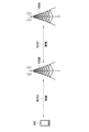
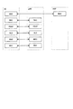
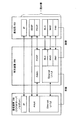
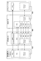
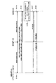
- FIG. 3 is an explanatory diagram for describing an example of a schematic configuration of a system 1 according to an embodiment of the present disclosure. It is an explanatory view for explaining an outline about an example of relay communication. It is an explanatory view for explaining an outline about an example of relay communication in the system concerning the embodiment. It is explanatory drawing for demonstrating an outline about another example of the relay communication in the system which concerns on the same embodiment. It is a figure showing an example of a frame composition of Ethernet. It is the figure which showed an example of the protocol stack of the data communication in NR. It is the figure which showed an example of the data flow in the layer 2 of NR. It is a figure showing an example of a protocol stack of control information communication in NR.
- FIG. 4 is a block diagram illustrating a first example of a schematic configuration of an eNB. It is a block diagram which shows the 2nd example of schematic structure of eNB. It is a block diagram showing an example of a schematic structure of a smart phone. It is a block diagram showing an example of a schematic structure of a car navigation device.
- FIG. 1 is an explanatory diagram for describing an example of a schematic configuration of a system 1 according to an embodiment of the present disclosure.
- the system 1 includes a wireless communication device 100 and a terminal device 200.
- the terminal device 200 is also called a user.
- the user may also be referred to as a UE.
- the wireless communication device 100C is also called UE-Relay.
- the UE herein may be a UE defined in LTE or LTE-A, and the UE-Relay may be a Prose UE to Network Relay discussed in 3GPP, and more generally communicates. It may mean a device.
- the wireless communication device 100 is a device that provides a wireless communication service to a device under its control.
- the wireless communication device 100A is a base station of a cellular system (or mobile communication system).
- the base station 100A performs wireless communication with a device (for example, the terminal device 200A) located inside the cell 10A of the base station 100A.
- the base station 100A transmits a downlink signal to the terminal device 200A and receives an uplink signal from the terminal device 200A.
- the base station 100A is logically connected to another base station by, for example, an X2 interface, and can transmit / receive control information and the like. Further, the base station 100A is logically connected to a so-called core network (not shown) by, for example, the S1 interface, and can transmit / receive control information and the like. Communication between these devices can be physically relayed by various devices.
- the wireless communication device 100A shown in FIG. 1 is a macrocell base station, and the cell 10A is a macrocell.
- the wireless communication devices 100B and 100C are master devices that operate the small cells 10B and 10C, respectively.
- the master device 100B is a small cell base station fixedly installed.
- the small cell base station 100B establishes a wireless backhaul link with the macrocell base station 100A and an access link with one or more terminal devices (for example, the terminal device 200B) in the small cell 10B.
- the wireless communication device 100B may be a relay node defined by 3GPP.
- the master device 100C is a dynamic AP (access point).
- the dynamic AP 100C is a mobile device that dynamically operates the small cell 10C.
- the dynamic AP 100C establishes a wireless backhaul link with the macrocell base station 100A and an access link with one or more terminal devices (for example, the terminal device 200C) in the small cell 10C.
- the dynamic AP 100C may be, for example, a terminal device equipped with hardware or software operable as a base station or a wireless access point.
- the small cell 10C in this case is a dynamically formed local network (Localized Network / Virtual Cell).
- the cell 10A is, for example, any wireless communication method such as LTE, LTE-A (LTE-Advanced), LTE-ADVANCED PRO, GSM (registered trademark), UMTS, W-CDMA, CDMA200, WiMAX, WiMAX2 or IEEE802.16. May be operated according to.
- the small cell is a concept that can include various types of cells (for example, femtocells, nanocells, picocells, and microcells) that are arranged to overlap or not overlap with the macrocell and are smaller than the macrocell.
- the small cell is operated by a dedicated base station.
- the small cell is operated by a terminal serving as a master device temporarily operating as a small cell base station.
- So-called relay nodes can also be considered as a form of small cell base station.
- a wireless communication device that functions as a master station of a relay node is also called a donor base station.
- the donor base station may mean a DeNB in LTE, and more generally a master station of a relay node.
- Terminal device 200 The terminal device 200 can communicate in a cellular system (or a mobile communication system).
- the terminal device 200 performs wireless communication with a wireless communication device of the cellular system (for example, the base station 100A, the master device 100B or 100C).
- a wireless communication device of the cellular system for example, the base station 100A, the master device 100B or 100C.
- the terminal device 200A receives the downlink signal from the base station 100A and transmits the uplink signal to the base station 100A.
- the terminal device 200 is not limited to a so-called UE, and for example, a so-called low cost terminal (Low cost UE) such as an MTC terminal, an eMTC (Enhanced MTC) terminal, and an NB-IoT terminal may be applied.
- a so-called low cost terminal such as an MTC terminal, an eMTC (Enhanced MTC) terminal, and an NB-IoT terminal may be applied.
- the present technology is not limited to the example illustrated in FIG. 1.
- a configuration not including a master device SCE (Small Cell Enhancement), HetNet (Heterogeneous Network), MTC network, or the like may be adopted.
- a master device may be connected to a small cell and a cell may be constructed under the control of the small cell.
- a communication device configured to be communicable with the terminal device 200 via a wired or wireless communication path (hereinafter, referred to as “communication device 300” for convenience). (Also referred to as)) may be included.
- the terminal device 200 may play a role as a so-called relay communication device that relays communication between the base station 100 and the communication device 300.
- communication having different communication methods may be applied to the communication between the base station 100 and the terminal device 200 and the communication between the terminal device 200 and the communication device 300.
- Robot communication requirements Next, the outline of requirements for communication when NR is applied to control of a robot or the like will be described.
- the use of a robot via communication is being considered.
- Remote surgery using a surgery support robot ⁇ Automatic control of trains, automobiles, drones, etc. (that is, moving bodies) ⁇ Remote control ⁇ Factory automation and building automation ⁇ Communication between devices inside the robot
- robot communications In communications that assume the use of robots (hereinafter also referred to as “robot communications”), low latency (round latency) of 1 millisecond or less in the physical layer and packet error rate of 0.001% or less are used. Achieved communication reliability (Ultra-reliability), high service availability (Communication service availability), which is always available when an application wants to communicate.
- NR and LTE have introduced low-delay and high-reliability technologies such as data duplication and low-delay slots.
- low-delay and high-reliability technologies such as data duplication and low-delay slots.
- it is possible to realize highly reliable wireless communication by making data redundant by using a large amount of wireless resources.
- wireless resources such as frequency bands are limited, it may be difficult to realize wireless low-delay and highly reliable communication on all routes.
- wired communication is applied to some communication paths and wireless communication is applied to other communication paths.
- wireless communication is applied to other communication paths.
- Types of robot communication information In robot communication according to an embodiment of the present disclosure, various types of information exchange may be envisioned. Information exchanged by robot communication can be classified into, for example, information that requires real-time processing and information that does not necessarily require real-time processing. Examples of information that requires real-time property include information that is guaranteed by QoS. In addition, examples of information that does not necessarily require real-time processing include information that does not necessarily require QoS guarantee.
- Motion information directly related to movement for example, control information for actuators
- Sensor information Control information when an emergency occurs (for example, when a collision crisis occurs)
- Log data for example, robot joint angle trajectory, error information, event (when an event occurs at a certain time), past sensor information, etc.
- Information exchange at initialization information at the planning stage
- Information exchange at initialization information at the planning stage
- connection setup-Information about movement plans-Information that can be thought of by the human cerebrum-Sensor information measured at a position farther from the moving robot
- a relay may be adopted for the purpose of extending cell coverage or improving the quality of a received signal.
- FIG. 2 is an explanatory diagram for explaining an outline of an example of relay communication.
- communication between the base station 100A and the terminal device 200 is performed via the relay base station 100B.
- communication is performed between the base station 100A and the relay base station 100B via a wireless communication path, and the wireless communication path is also between the relay base station 100A and the terminal device 200.
- Communication is performed via. Accordingly, for example, even when it is difficult for the terminal device 200 to directly receive the signal from the base station 100 due to the influence of the propagation loss, it is possible to deliver the signal to the terminal device 200 with good quality. Becomes
- wireless-wired mixed relay communication communication via a wireless communication path (hereinafter, simply referred to as “wireless communication”) and communication via a wired communication path (hereinafter, also simply referred to as “wired communication”)
- wireless communication communication via a wireless communication path
- wired communication communication via a wired communication path
- relay communication in which a wired communication path is applied in a part of a series of communication paths to relay communication in conventional wireless communication (hereinafter, , Also referred to as “wireless-wired relay communication”).
- wireless-wired relay communication An example of the operation of wireless-wired relay communication that can be assumed in the system according to the present embodiment is an operation that uses wireless communication for long-distance transmission.
- the wiring cost may increase in proportion to the communication distance.
- the wireless communication when the wireless communication is realized, the above wiring cost may be substantially unnecessary, so that the effect of cost reduction is expected especially in long-distance communication.
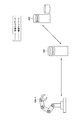
- FIG. 3 is an explanatory diagram for explaining an outline of an example of relay communication in the system according to the present embodiment, and shows an example of relay communication in which wireless communication and wire communication are mixed.
- FIG. 3 assumes communication between the robot 530 (device having a communication function) and a cloud server 510 installed in a remote place, and communication between the robot 530 and another robot 530. It shows an example of a schematic configuration of the system.
- a case can be assumed in which the robot 530 receives various kinds of information in real time and operates according to the situation on the spot.
- remote robot control such as remote surgery, control robot that is supposed to operate in the factory, external sensors such as traffic signal information and camera information installed on the side of the road
- external sensors such as traffic signal information and camera information installed on the side of the road
- the base station 100 and the terminal device 200-1 are used to realize communication between the cloud server 510 and the robot 530-1.
- the base station 100 and the cloud server 510 are connected via a wired communication path N123.
- the terminal device 200-1 and the robot 530-1 are connected via a wired communication path N117.
- the base station 100 and the terminal device 200-1 are connected via a wireless communication path N111.
- the data transmitted from the robot 530-1 is transmitted via the terminal device 200-1 and the base station 100 (that is, the reference It is transmitted to the cloud server 510 (via the communication path denoted by reference numeral D101) and is received by the cloud server 510.
- the base station 100, the terminal device 200-1, and the terminal device 200-2 are used to realize communication between the robot 530-2 and the robot 530-3.
- the terminal device 200-1 and the robot 530-2 are connected via a wired communication path N115.
- the terminal device 200-2 and the robot 530-3 are connected via a wired communication path N119.
- the base station 100 and the terminal device 200-1 are connected via a wireless communication path N111.
- the base station 100 and the terminal device 200-2 are connected via a wireless communication path N113.
- the data transmitted from the robot 530-2 is the terminal device 200-1, the base station 100, and the terminal device 200-.
- the robot 530-3 may directly perform wireless communication with the base station 100.
- FIG. 4 is an explanatory diagram for explaining an outline of another example of relay communication in the system according to the present embodiment, and shows an example of relay communication in which wireless communication and wire communication are mixed. Specifically, FIG. 4 shows an example in which wireless communication is applied to communication between devices inside the robot 530-4.
- the example shown in FIG. 4 is a communication system including communication between devices inside the robot such as a CPU and an actuator, and communication between the robot and a control server that controls the operation of the robot.
- wireless communication is applied to the transmission and reception of information between the devices inside the robot 530-4.
- Wired communication is applied between the robot 530-4 and the control server 520 that controls the operation of the robot 530-4, in order to further reduce the influence from other wireless communication. Wired communication is also applied between the control server 520 and the core network 400.
- information regarding control of a device such as an actuator transmitted from the control server 520 can be obtained by wired communication between the control server 520 and the robot 530-4 and between devices inside the robot 530-4. Wireless communication. As a result, it is possible to realize a robot with a wider range of motion than in the past.
- Protocol stack ⁇ 1.5. Protocol stack> Next, an example of the protocol stack in the system according to the embodiment of the present disclosure will be described. In addition, the protocol stack in this description represents a layer of a network protocol.
- the protocol stack is composed of a physical layer, a link layer, a network layer, a transport layer, and an application layer from the lower layer.
- the physical layer is a layer that performs conversion processing for flowing the signal transferred from the upper layer to the propagation path and conversion processing for correctly transferring the signal received after being transmitted through the propagation path to the upper layer.
- the link layer is a layer having functions such as transmission control, error detection, and retransmission request.
- the network layer is a layer that controls allocation of IP addresses, selection of data transmission paths (routing), and the like.
- the network layer corresponds to, for example, the IP layer.
- the transport layer is a layer that controls the transfer of data.
- the transport layer corresponds to, for example, a TCP layer and a UDP layer.
- the application layer is, for example, a layer for applications to communicate.
- Ethernet is a standard for a wired LAN (Local Area Network) that defines some protocols of the physical layer and data link layer.
- LTE and NR are standards for mobile networks in which the protocols of the physical layer and the data link layer are defined.
- the protocol stack lower than the IP layer in Ethernet is composed of two layers, a physical layer (PHY layer, L1) and a data link layer (L2).
- PHY layer physical layer
- L2 data link layer
- processing for example, modulation and demodulation
- L1 physical layer
- L2 data link layer
- processing for example, modulation and demodulation
- L2 data link layer
- processing relating to creation of a MAC frame to be transmitted and interpretation of the received MAC frame is performed.
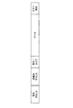
- FIG. 5 is a diagram showing an example of an Ethernet frame structure. As shown in FIG. 5, in the Ethernet frame, a destination address (MAC address), a source address (MAC address), length / type information, data, and a parity bit for error detection are arranged in this order. Consists of
- FIG. 6 is a diagram showing an example of a protocol stack of data communication (U-Plane, User-Plane) in NR.
- the protocol stack for NR data communication includes a PHY layer (Physical layer), a MAC layer (Medium Access Control layer), an RLC layer (Radio Link Control Layer), and a PDCP layer (Packet Data Convergence) from the lower layer. Protocol layer) and an SDAP layer (Service Data Adaptation Protocol layer).
- Layer 1 corresponds to the PHY layer.
- Layer 2 is composed of a MAC layer, an RLC layer, a PDCP layer, and a sublayer of an SDAP layer.
- An upper layer such as an IP layer exists above the SDAP layer.
- MAC SDU Service Data Unit
- MAC SDU Service Data Unit
- HARQ Hybrid Automatic Repeat and processing such as "error correction using reQuest”, “priority handling between terminals or logical channels”, and “padding”.
- PDCP layer for example, "sequence numbering”, “header compression and decompression”, “reordering and duplicate detection”, “routing”, “retransmission”, “encryption, decryption and integrity protection”, and “data decompression”. , And processing such as “duplication” are executed.
- SDAP layer for example, processing such as "mapping between data and QoS flow” and “masking of QoS flow ID” is executed. Note that the LTE does not use the SDAP layer.
- FIG. 7 is a diagram showing an example of a data flow in the layer 2 of NR.
- the IP packet transferred from the upper layer IP layer
- IP layer IP layer
- SDAP SDU Secure Digital
- SDP PDU Protocol Data Unit
- the SDAP PDU transferred from the SDAP layer is converted into a PDCP SDU, and then a header is added to generate the PDCP PDU.
- the PDCP PDU transferred from the PDCP layer is converted to an RLC SDU, and then a header is added to generate an RLC PDU.
- RLC SDU RLC SDU
- PDCP PDU can be divided in the RLC layer.
- the RLC PDU transferred from the RLC layer is converted to a MAC SDU, and then a header is added to generate a MAC PDU.
- MAC SDUs can be multiplexed to generate one MAC PDU.
- FIG. 8 is a diagram showing an example of a protocol stack of control information communication (C-Plane, Control-Plane) in NR.
- the protocol stack for NR control information communication is composed of a PHY layer, a MAC layer, an RLC layer, a PDCP layer, an RRC layer (Radio Resource Control layer), and a NAS layer (Non-Access Stratum layer) from the lower layer.
- Layer 3 corresponds to the RRC layer and NAS layer.
- AMF Access and Mobility Management Function
- the RRC layer in this example is a configuration included in the base station, but the present invention is not limited to this configuration, and the RRC layer may be present in the core network.
- RRC layer for example, “notification of system information”, “paging”, “establishment, maintenance and release of connection between terminal device and network”, “security”, “establishment, setting, maintenance and release of data flow”. “Handover, content transfer, and mobility processing such as cell selection / reselection”, “QoS management”, “measurement report and report control”, and “link failure detection and restoration” are executed. It
- FIG. 9 is a diagram showing an example of a protocol stack of data communication in relay communication in which wireless communication and wired communication are mixed.
- wireless communication using NR is applied to the transmission path between the base station 100 and the terminal device 200, and the terminal device 200 and a device such as a cloud server or a robot (hereinafter, for convenience, Wired communication using Ethernet is applied to a transmission line between the communication device 300 and the communication device 300.
- a device such as a cloud server or a robot
- Wired communication using Ethernet is applied to a transmission line between the communication device 300 and the communication device 300.
- the upper layers higher than the IP layer are not shown.
- NR and Ethernet have different physical layer and link layer standards
- data when data is transmitted between the base station 100 and the communication device 300, it is a common layer in the terminal device 200 that relays the transmission. Data is transferred to the IP layer. Then, in the terminal device 200, the format of the data is converted into the format of the physical layer and the link layer corresponding to each standard (for example, replacement of the header according to the communication standard).
- the data transmitted from the base station 100 is transferred from the IP layer to the SDAP layer, the PDCP layer, the RLC layer, the MAC layer, and the PHY layer in this order on the side of the base station 100, and the data is transmitted via the wireless transmission path to the terminal. It is transmitted to the device 200.
- the terminal device 200 transfers the received wireless signal (data) in the order of the PHY layer, the MAC layer, the RLC layer, the PDCP layer, and the SDAP layer, and converts it into data corresponding to the IP layer.
- the target data is Ethernet layer 2 (L2) and Ethernet layer 1 (L2) after conversion between transmission paths in the IP layer is performed.
- the communication device 300 transfers the received wired signal (data) in the order of the layer 1 (L1) and the layer 2 (L2) of Ethernet, and converts it into data corresponding to the IP layer. Data is transmitted from the base station 100 to the communication device 300 by performing the above-described series of procedures.
- protocol conversion for example, header replacement, etc.
- data is transferred from the lower layer to a predetermined upper layer in the protocol stack before the conversion, and the conversion is performed.
- the operation of transferring to a lower layer again in a later protocol stack is also referred to as “folding”.
- layer that performs folding back indicates the layer that performs protocol conversion between communications of different communication methods.
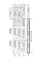
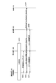
- FIG. 10 is an explanatory diagram for explaining an outline of an example of delay in relay communication in which communication of different communication systems is mixed, and an example of transmission / reception resource allocation when independent QoS control is performed on each route. It is the figure which showed.
- the horizontal axis represents time.
- the protocol since the protocol is converted up to the IP layer, a delay due to the protocol conversion process may occur.
- the radio signal (data) transmitted from the base station 100 to the terminal device 200 to the IP layer it has to go through five layers.
- the information regarding the device control of the robot may have a small amount of information (the number of bits), and thus packet division and combination processing may be unnecessary.
- the ratio of the header attached in each layer is relatively increased as compared with the information about the device control of the robot, and there is a possibility that it becomes communication overhead and becomes inefficient control.
- CSMA / CD Carrier Sense Multiple Access / Collision Detection
- fine orthogonal resource allocation such as time division multiplexing and frequency division multiplexing may not be performed.
- the present disclosure proposes a protocol stack and a resource control method that solves the above problems.
- FIG. 11 is a block diagram showing an example of the configuration of the base station 100 according to an embodiment of the present disclosure.
- the base station 100 includes an antenna unit 110, a wireless communication unit 120, a network communication unit 130, a storage unit 140, and a control unit 150.
- Antenna unit 110 The antenna unit 110 radiates a signal output by the wireless communication unit 120 into space as a radio wave. Further, the antenna unit 110 converts a radio wave in the space into a signal and outputs the signal to the wireless communication unit 120.
- the wireless communication unit 120 transmits and receives signals. For example, the wireless communication unit 120 transmits a downlink signal to the terminal device and receives an uplink signal from the terminal device.
- the network communication unit 130 transmits and receives information.
- the network communication unit 130 transmits information to another node and receives information from another node.
- the other nodes include other base stations and core network nodes.
- Storage unit 140 The storage unit 140 temporarily or permanently stores a program for the operation of the base station 100 and various data.
- Control unit 150 provides various functions of the base station 100.
- the control unit 150 includes a communication control unit 151, an information acquisition unit 153, and a notification unit 155. It should be noted that the control unit 150 may further include components other than these components. That is, the control unit 150 can perform operations other than the operations of these components.
- the communication control unit 151 executes various processes related to control of wireless communication with the terminal device 200 via the wireless communication unit 120. Further, the communication control unit 151 executes various processes related to control of communication with other nodes (for example, other base stations, core network nodes, etc.) via the network communication unit 130.
- other nodes for example, other base stations, core network nodes, etc.
- the information acquisition unit 153 acquires various information from the terminal device 200 and other nodes.
- the acquired information may be used, for example, for control of wireless communication with the terminal device, control for cooperation with another node, or the like.
- the notification unit 155 notifies the terminal device 200 and other nodes of various information.
- the notification unit 155 may notify the terminal device 200 of various information for the terminal device 200 in the cell to perform wireless communication with the base station 100.
- the notification unit 155 may notify the information acquired from the terminal device in the cell to another node (for example, another base station).
- the notification unit 155 notifies the terminal device 200 in the cell of information for the terminal device 200 to communicate with another communication device (for example, the communication device 300 such as a cloud server or a robot). You may.
- FIG. 12 is a block diagram showing an example of the configuration of the terminal device 200 according to an embodiment of the present disclosure.
- the terminal device 200 includes an antenna unit 210, a wireless communication unit 220, a storage unit 230, and a control unit 240.
- the terminal device 200 may relay communication between another communication device (for example, a communication device 300 such as a cloud server or a robot) and the base station 100.
- the terminal device 200 may include a network communication unit 250 for communicating with the other communication device (hereinafter, referred to as the communication device 300).
- Antenna unit 210 The antenna unit 210 radiates the signal output from the wireless communication unit 220 into space as a radio wave. Further, the antenna unit 210 converts a radio wave in space into a signal, and outputs the signal to the wireless communication unit 220.
- Wireless communication unit 220 Wireless communication section 220 transmits and receives signals.
- the wireless communication unit 220 receives a downlink signal from a base station and transmits an uplink signal to the base station.
- the terminal device 200 may directly communicate with another terminal device 200 without going through the base station 100.
- the wireless communication unit 220 may send and receive a side link signal with another terminal device 200.
- Storage unit 230 The storage unit 230 temporarily or permanently stores a program for operating the terminal device 200 and various data.
- the network communication unit 250 sends and receives information.
- the network communication unit 250 transmits information to another communication device 300 and receives information from another communication device 300.
- the communication device 300 may include, for example, another device having a communication function such as a cloud server or a robot.
- Control unit 240 provides various functions of the terminal device 200.
- the control unit 240 includes a communication control unit 241, an information acquisition unit 243, and a notification unit 247. It should be noted that the control unit 240 may further include components other than these components. That is, the control unit 240 can also perform operations other than the operations of these components.
- the communication control unit 241 executes various processes related to control of wireless communication with the base station 100 via the wireless communication unit 220. Further, the communication control unit 241 executes processing related to control of communication with the communication device 300 via the network communication unit 250.
- the communication control unit 241 may execute various processes related to relay of communication (that is, data transmission) between the base station 100 and the communication device 300.
- the communication control unit 241 converts one of the data transmitted to the base station 100 and the data transmitted to the communication device 300 into the other, Communication between the base station 100 and the communication device 300 may be relayed. The details of this process will be described later.
- the information acquisition unit 243 acquires various types of information from the base station 100 and other communication devices 300. As a specific example, the information acquisition unit 243 may acquire information related to relay of communication between the base station 100 and the communication device 300 from the base station 100 or the communication device 300.
- the notification unit 247 notifies the base station 100 and other communication devices 300 of various information.
- the notification unit 247 may notify the base station 100 or the communication device 300 of information related to relaying communication between the base station 100 and the communication device 300.
- FIG. 13 is a block diagram showing an example of a configuration of the communication device 300 according to an embodiment of the present disclosure, and shows an example of a functional configuration of a device having a communication function such as a cloud server or a robot.
- the communication device 300 includes a network communication unit 310, a storage unit 320, and a control unit 330.
- the network communication unit 310 sends and receives information.
- the network communication unit 310 transmits information to the terminal device 200 and receives information from the terminal device 200.
- the communication method by which the network communication unit 310 transmits / receives information to / from another communication device is not particularly limited, and may be appropriately changed depending on, for example, the type of the communication path with the other communication method. Good.
- the type of the communication path through which the network communication unit 310 transmits / receives information to / from another communication device is not particularly limited, and may be, for example, a wired communication path or a wireless communication path. Good.
- Storage unit 320 The storage unit 320 temporarily or permanently stores a program and various data for the operation of the communication device 300.
- Control unit 330 provides various functions of the communication device 300.
- the control unit 330 includes a communication control unit 331, an information acquisition unit 333, and a notification unit 335. It should be noted that the control unit 330 may further include components other than these components. That is, the control unit 330 can perform operations other than the operations of these components.
- the communication control unit 331 executes various processes related to control of communication with another communication device (for example, the terminal device 200) via the network communication unit 310.
- the communication control unit 331 may decode the data transmitted from the base station 100 based on the relay by the terminal device 200 according to the relay mode. Further, the communication control unit 331 may encode the data to be transmitted to the base station 100 based on the relay by the terminal device 200 according to the relay mode. The details of these processes will be described later.
- the information acquisition unit 333 acquires various kinds of information from the base station 100 and the terminal device 200. As a specific example, the information acquisition unit 333 may acquire information for performing communication with the base station 100 based on relay by the terminal device 200, from the base station 100 or the terminal device 200.
- the notification unit 335 notifies the base station 100 and the terminal device 200 of various information.
- the notification unit 335 may notify the base station 100 or the communication device 300 of information related to communication with the base station 100 based on relay by the terminal device 200.
- the conversion from one of the data transmitted by wireless communication and the data transmitted by wired communication to the other is performed by the IP layer of the series of layers forming the protocol stack. Is also performed in the lower layer (in other words, any layer below the layer corresponding to the communication protocol related to the selection of the transmission path).
- FIG. 14 is an explanatory diagram for explaining an example of a protocol stack in the system according to the present embodiment, and shows an example of a protocol stack assuming relay communication in which wireless communication and wire communication are mixed.
- processing related to conversion between data transmitted via wireless communication and data transmitted via wired communication is performed in the SDAP layer.
- An adaptation layer is inserted (set) in the protocol stack on the wired communication side as a layer corresponding to the SDAP layer of NR.
- Ethernet L1 / L2 processing is performed based on the QoS flow defined in the SDAP layer.
- the process related to transmission / reception is executed so that the SDP A PDU having a higher QoS priority is given higher priority.
- the terminal device 200 corresponds to an example of a communication device that relays communication between the base station 100 and the communication device 300.
- the communication unit for example, the wireless communication unit 220 illustrated in FIG. 12
- the communication method for the first communication unit to communicate with another communication device corresponds to an example of “first communication method”. That is, in the case of the example shown in FIG. 14, the communication method for performing communication between the terminal device 200 and the base station 100 via the wireless communication path corresponds to an example of the “first communication method”.
- a communication unit for example, the network communication unit 250 shown in FIG. 12 that communicates with another communication device (for example, the communication device 300) based on a communication system different from the first communication system is provided.
- another communication device for example, the communication device 300
- the communication method for the second communication unit to communicate with another communication device corresponds to an example of the “second communication method”. That is, in the case of the example shown in FIG. 14, the communication method for performing communication between the terminal device 200 and the communication device 300 via the wired communication path corresponds to an example of the “second communication method”.
- the base station 100 that the third communication device communicates with based on the first communication method corresponds to an example of the “first communication device”. Further, the communication device 300 that performs communication based on the second communication method by the third communication device corresponds to an example of “second communication device”. The same applies to the examples shown in FIGS. 15 to 17 whose details will be described later.
- the SDAP layer in which a protocol conversion is performed at the time of data transfer among the series of layers defined as the NR protocol stack corresponds to an example of the “first layer”.
- the adaptation layer inserted (set) corresponding to the SDAP layer corresponds to an example of the “second layer”.
- FIG. 15 is an explanatory diagram for explaining another example of the protocol stack in the system according to the present embodiment, and shows another example of the protocol stack assuming relay communication in which wireless communication and wired communication are mixed.
- the PDCP layer processing relating to conversion between data transmitted via wireless communication and data transmitted via wired communication is performed.
- An adaptation layer (adaptation layer) is inserted (set) in the protocol stack on the wired communication side as a layer corresponding to the SDAP layer and the PDCP layer of the NR.
- the Ethernet L1 / L2 process is performed after the operation performed in the PDCP layer is performed in the adaptation layer of the terminal device 200.
- the terminal device 200 transfers the data without performing the processing performed in the SDAP layer.
- the QoS flow control is not performed, and the data transfer is performed based on the control designated in advance by the RRC setting.
- the PDCP layer that performs protocol conversion during data transfer corresponds to an example of the “first layer”.
- the adaptation layer inserted (set) corresponding to the PDCP layer corresponds to an example of the “second layer”.
- FIG. 16 is an explanatory diagram for explaining another example of the protocol stack in the system according to the present embodiment, and shows another example of the protocol stack assuming relay communication in which wireless communication and wired communication are mixed.
- the RLC layer a process related to conversion between data transmitted via wireless communication and data transmitted via wired communication is performed.
- an adaptation layer is inserted (set) as a layer corresponding to the SDAP layer, PDCP layer, and RLC layer of NR.
- the processing of Ethernet L1 / L2 is performed after the operation performed in the RLC layer.
- the terminal device 200 transfers the data without performing the processing performed in the SDAP layer and the PDCP layer. Specifically, the terminal device 200 does not perform encryption, combination, or consistency check. That is, the same cipher is used for wired communication and wireless communication.
- the RLC layer that performs protocol conversion during data transfer corresponds to an example of the “first layer”.
- the adaptation layer inserted (set) corresponding to the RLC layer corresponds to an example of the “second layer”.
- FIG. 17 is an explanatory diagram for explaining another example of the protocol stack in the system according to the present embodiment, showing another example of the protocol stack assuming relay communication in which wireless communication and wired communication are mixed.
- the MAC layer a process related to conversion between data transmitted via wireless communication and data transmitted via wired communication is performed.
- An adaptation layer is inserted on the wired communication side as a layer corresponding to the SDAP layer, PDCP layer, RLC layer, and MAC layer of NR.
- the adaptation layer of the terminal device 200 performs the operation performed in the MAC layer and then the Ethernet L1 process.
- the terminal device 200 transfers the data without performing the processing performed in the SDAP layer, the PDCP layer, and the RLC layer. Specifically, in each path, error correction by RLC is not performed and RLC retransmission is not performed. This is expected to further reduce the delay.
- the MAC layer that performs protocol conversion at the time of data transfer corresponds to an example of the “first layer”.
- the adaptation layer inserted (set) corresponding to the MAC layer corresponds to an example of the “second layer”.
- the base station or the core network can select one of the protocol stacks of the above-mentioned data communication (U-Plane) according to various situations.
- the base station or the core network may select a more appropriate protocol stack (for example, a request specification having a more preferable aspect from among the above-mentioned data communication protocol stacks) according to the state of the communication path and the type of packet.
- the protocol stack achievable in () can be selected.
- the terminal device 200 be controlled so as to be folded back in a layer lower than the RLC layer (that is, protocol conversion is performed in a layer lower than the RLC layer). By such control, the delay due to the protocol conversion is shortened, and it becomes possible to realize communication with lower delay.
- a block error probability tends to be high in a route where the environment of the communication channel is bad (low SINR, low reliability, etc.) such as long-distance communication. Therefore, for example, it is preferable that the terminal device 200 be controlled so that the terminal device 200 returns to the layer above the RLC layer (that is, performs protocol conversion in the layer above the RLC layer). By such control, ARQ processing is performed in the RLC layer, and more stable communication can be realized.
- delay is an example of the status of the route.
- a route with a large end-to-end delay such as long-distance communication or relays that are repeated a plurality of times
- a short-distance path with a small propagation delay it may be controlled so as to be folded back in a higher layer.
- Information that requires real-timeness is an example of the type of packet.
- information that requires real-time property it is more preferable that the information is folded back to a lower layer as in the example described with reference to FIGS. 16 and 17.
- information that does not require real-time processing it is preferable to return the information in a higher layer as in the example described with reference to FIGS. 14 and 15.
- Adaptation layer At the adaptation layer, at least one of conversion from an NR frame structure to an Ethernet frame structure and vice versa is performed. As a specific example, insertion and removal of Ethernet header information (destination MAC address, source MAC address, length / type information, etc.) is performed in the adaptation layer. The content of the Ethernet header information to be added is set in advance based on the communication settings from the base station 100, for example.
- the processing of the NR layer, which has not been processed by other communication devices is performed due to the loopback during relay.
- the terminal device 200 that relays the communication between the base station 100 and the communication device 300 when the ARQ control in the RLC layer is not performed due to the return in the layer lower than the RLC layer, the communication device ARQ control in the RLC layer is performed in the adaptation layer of 300.
- encryption, decryption, and integrity protection are performed in the PDCP layer due to the return at a layer lower than the PDCP layer. If not, encryption, decryption, and integrity protection in the PDCP layer are performed in the adaptation layer of the communication device 300.
- the base station 100 includes a subordinate terminal device or a wired communication device 300 (for example, a cloud server or a robot). Communication setting (RRC setting) in advance.
- a subordinate terminal device or a wired communication device 300 for example, a cloud server or a robot.
- RRC setting Communication setting
- FIG. 18 is a diagram showing an example of a protocol stack of control signal communication (C-Plane) in the system according to an embodiment of the present disclosure.
- C-Plane control signal communication
- RRC is set from the base station 100 to each of the communication device 300 (for example, a cloud server, a robot, etc.) and the terminal device 200.
- the core network 400 authenticates each of the communication device 300 and the terminal device 200 in the NAS layer.
- FIG. 19 is a sequence diagram showing an example of a flow of a series of processes of RRC setting and relay communication in the system according to the present embodiment.
- the example illustrated in FIG. 19 is a sequence in which the terminal device 200 relays communication between the base station 100 and the communication device 300 (for example, a device having a communication function such as a cloud server or a robot). 7 shows an example of the flow of the above process.
- the terminal device 200 and the communication device 300 measure the delay of a communication path (for example, a wired communication path or a wireless communication path) (S101a, S101b).
- a communication path for example, a wired communication path or a wireless communication path
- a predetermined data signal for example, a test signal such as ping, dummy data, data including the transmission time, etc.
- the time until a response is returned is measured. And the like.
- the terminal device 200 and the communication device 300 report the measurement information regarding the delay and the information regarding the capability regarding the delay to the base station 100 (S103).
- the measurement information related to the delay for example, the measurement result of the delay of the communication path described above can be mentioned.
- the information on the capability related to the delay includes, for example, the communication processing capability related to the time required for protocol conversion and the like, the processing capability related to signal transmission / reception, and the like.
- the terminal device 200 and the communication device 300 may also report information regarding communication traffic to the base station 100.
- Examples of information regarding communication traffic include traffic type (information regarding QoS) and traffic volume (for example, Buffer Status Report).
- the base station 100 determines a communication path and a transmission / reception resource corresponding to each QoS, a data communication (U-plane) protocol stack, and the like based on the information notified from the terminal device 200 and the communication device 300 (S105).
- a communication path and a transmission / reception resource corresponding to each QoS determined by the base station 100, and a data communication (U-plane) protocol stack are set in the terminal device 200 and the communication device 300 by RRC, for example (S107). .
- each of the terminal device 200 and the communication device 300 starts communication based on the RRC setting (S109).
- FIG. 20 is an explanatory diagram for explaining an example of an initial connection sequence of a wired terminal (communication device 300) connected to the core network via a wired communication path.
- the conventional terminal device 200 wireless terminal
- FIG. 20 it is assumed that the conventional terminal device 200 (wireless terminal) is already connected to the base station 100 or the core network 400.
- a device that can be connected to the core network by connecting to a device (for example, the terminal device 200) that performs wireless communication via a wired communication path is referred to as a “wired device”.
- Wired terminals have a variety of different properties than wireless terminals.
- the wired terminal may not measure the surrounding wireless environment (RRM measurement).
- the wired terminal may not report the measurement information of the surrounding wireless environment.
- the communication device 300 wireless terminal
- the terminal device 200 When the communication device 300 (wired terminal) and the terminal device 200 are connected via a wired communication path (S201), first, the setup of the wired connection between the communication device 300 and the terminal device 200 is started. (S203). In the wired connection setup, the communication device 300 makes a connection request to the terminal device 200. Upon receiving the request, the terminal device 200 provides the communication device 300 with the setting information. The communication device 300 sets wired communication based on the setting information provided from the terminal device 200. Examples of the setting information include information such as resource cycles.
- the communication device 300 connects to the base station 100 and the core network 400 (for example, the MME 410) via the terminal device 200. Specifically, the communication device 300 performs NAS (Non-Access Stratum) attachment, authentication, and encryption setup with the base station 100 (S205). By performing these processes, the communication device 300 completes the connection to the core network 400 (for example, the MME 410) (S207).
- NAS Non-Access Stratum
- the base station 100 sets the resource control for the terminal device 200 and the communication device 300 (S209, S211).
- resource control settings include setting of resource cycles and bandwidths.
- the base station 100 grasps the traffic volume of each of the wireless communication path and the wired communication path, and time-divisionally or frequency-divides each communication device (for example, the terminal device 200, the communication device 300, etc.). ), It becomes possible to perform more appropriate communication management as a system. This makes it possible to ensure the end-to-end delay even in a situation where a plurality of communications having different communication methods are mixed, such as a wired communication path and a wireless communication path.
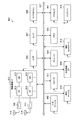
- FIG. 21 is an explanatory diagram illustrating an outline of an example of delay in relay communication according to an embodiment of the present disclosure, and illustrates an example of transmission / reception resource allocation for wired communication and wireless communication.
- the horizontal axis represents time.
- the terminal device 200 when data is transmitted from the communication device 300 to the base station 100 via the terminal device 200, the data is transmitted via a wired communication path. It is also possible to set the wireless resource immediately after the step. By such control, the terminal device 200 minimizes the delay due to the transfer standby (ideally, without performing the transfer standby), and transmits the data transmitted from the communication device 300 via the wired communication path. Can be transferred to the base station 100 via a wireless communication path. That is, it is possible to further reduce the end-to-end delay between the communication device 300 and the base station 100.
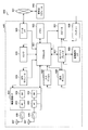
- FIG. 22 is a flowchart showing an example of the flow of processing for controlling the layer that performs protocol conversion (that is, the layer that performs loopback) based on header information.
- the terminal device 200 that relays communication between the communication device 300 and the base station 100 performs the protocol conversion, but the subject of the process illustrated in FIG. 22 is not necessarily limited. . That is, the process illustrated in FIG. 22 is not limited to the terminal device 200 as long as it is a device that performs the protocol conversion described above.
- the base station 100 (more specifically, a relay base station) performs the process. It may be the subject.
- the terminal device 200 when a PDU is transferred from a lower layer in a predetermined layer of a series of protocol stacks, the terminal device 200 analyzes the header corresponding to the layer to return the layer. Recognize information about. Examples of the information regarding the return of layers include information regarding QoS (delay request), information specifying a return layer (in other words, a layer that performs protocol conversion), information regarding transmission time, and the like. The terminal device 200 switches the subsequent processing based on the information regarding the turn-back of layers (S301).
- QoS delay request
- information specifying a return layer in other words, a layer that performs protocol conversion
- transmission time and the like.
- the terminal device 200 switches the subsequent processing based on the information regarding the turn-back of layers (S301).
- the terminal device 200 when the packet header includes information indicating layer folding (S301, YES), the terminal device 200 performs a layer folding process (S303).
- the terminal device 200 provides a protocol for a PDU based on the reception result from the base station 100, from a layer of a predetermined NR to an adaptation layer set to correspond to the layer in Ethernet. The conversion process is performed, and the PDU after the conversion process is transferred to the lower layer on the Ethernet side.
- the terminal device 200 performs, on the PDU based on the reception result from the communication device 300, a process reverse to the above, that is, a process of converting a protocol from the adaptation layer to the NR layer, The PDU after the conversion processing is transferred to a layer lower than the layer of the NR.
- the terminal device 200 performs the process in the layer (S305), and the SDU in the upper layer of the layer. To transfer.
- the above methods may be combined and applied.
- which layer below the layer is to be folded back (that is, protocol conversion)? May be configured so that the terminal device 200 determines according to the header information of the packet.
- the terminal device 200 can also selectively switch, for each packet, whether or not to perform folding back in any of the layers below the above-mentioned highest layer, based on the header information of the packet. Becomes
- FIG. 23 is an explanatory diagram for explaining an example of a schematic configuration when a plurality of relays are performed.
- the communication between the base station 100A and the terminal device 200 is relayed twice via the relay base stations 100B1 and 100B2.
- the relay base stations 100B1 and 100B2 are connected via a wired communication path.
- the base station 100A and the relay base station 100B1 are connected to each other, and the relay base station 100B2 and the terminal device 200 are connected to each other via a wireless communication path.
- FIG. 24 is an explanatory diagram for explaining an example of the data communication protocol stack according to the present embodiment, and shows an example of the protocol stack applicable to the system shown in FIG.
- the two relay base stations 100B1 and 100B2 loop back at the RLC layer (that is, perform protocol conversion at the RLC layer) and transfer data.
- FIG. 25 is an explanatory diagram for explaining another example of the data communication protocol stack according to the present embodiment, and shows another example of the protocol stack applicable to the system shown in FIG.
- the relay base station 100B1 returns data at the SDAP layer (that is, performs protocol conversion at the SDAP layer) and transfers data.
- the relay base station 100B2 returns data at the RLC layer (that is, performs protocol conversion at the RLC layer) and transfers data.
- the layers in which the return is performed are different between the relay base station 100B1 and the relay base station 100B2.
- the processing capability of a device that performs transfer (a specific example is a relay base station or a terminal device) and the device concerned May be determined according to the state of the communication path between the device and another device.
- the base station 100 may be implemented as an eNB (evolved Node B) of any type such as a macro eNB or a small eNB.
- the small eNB may be an eNB that covers a cell smaller than a macro cell, such as a pico eNB, a micro eNB, or a home (femto) eNB.
- the base station 100 may be realized as another type of base station such as a NodeB or a BTS (Base Transceiver Station).
- the base station 100 may include a main body (also referred to as a base station device) that controls wireless communication, and one or more RRHs (Remote Radio Heads) arranged in a place different from the main body.
- RRHs Remote Radio Heads
- various types of terminals described later may operate as the base station 100 by temporarily or semi-permanently executing the base station function.
- the terminal device 200 or 300 is a smartphone, a tablet PC (Personal Computer), a notebook PC, a portable game terminal, a mobile terminal such as a portable / dongle type mobile router or a digital camera, or a car navigation device. It may be realized as an in-vehicle terminal. Further, the terminal device 200 or 300 may be realized as a terminal that performs M2M (Machine To Machine) communication (also referred to as an MTC (Machine Type Communication) terminal). Furthermore, the terminal device 200 or 300 may be a wireless communication module mounted on these terminals (for example, an integrated circuit module configured by one base station 100 die).
- M2M Machine To Machine
- MTC Machine Type Communication
- FIG. 26 is a block diagram showing a first example of a schematic configuration of an eNB to which the technology according to the present disclosure can be applied.
- the eNB 800 has one or more antennas 810 and a base station device 820. Each antenna 810 and the base station device 820 can be connected to each other via an RF cable.
- Each of the antennas 810 has a single or a plurality of antenna elements (for example, a plurality of antenna elements forming a MIMO antenna), and is used for the base station device 820 to transmit and receive radio signals.
- the eNB 800 has a plurality of antennas 810 as shown in FIG. 26, and the plurality of antennas 810 may correspond to a plurality of frequency bands used by the eNB 800, respectively. 26 shows an example in which the eNB 800 has a plurality of antennas 810, the eNB 800 may have a single antenna 810.
- the base station device 820 includes a controller 821, a memory 822, a network interface 823, and a wireless communication interface 825.
- the controller 821 may be, for example, a CPU or a DSP, and operates various functions of the upper layer of the base station device 820. For example, the controller 821 generates a data packet from the data in the signal processed by the wireless communication interface 825, and transfers the generated packet via the network interface 823. The controller 821 may generate a bundled packet by bundling data from a plurality of baseband processors, and may transfer the generated bundled packet. Further, the controller 821 is a logic for executing control such as radio resource control (Radio Resource Control), radio bearer control (Radio Bearer Control), mobility management (Mobility Management), admission control (Admission Control) or scheduling (Scheduling). It may have a general function.
- Radio Resource Control Radio Resource Control
- Radio Bearer Control Radio Bearer Control
- Mobility Management Mobility Management
- Admission Control Admission Control
- scheduling scheduling
- the control may be executed in cooperation with the surrounding eNB or core network node.
- the memory 822 includes a RAM and a ROM, and stores a program executed by the controller 821 and various control data (for example, a terminal list, transmission power data, scheduling data, and the like).
- the network interface 823 is a communication interface for connecting the base station device 820 to the core network 824.
- the controller 821 may communicate with a core network node or another eNB via the network interface 823.
- the eNB 800 and the core network node or another eNB may be connected to each other by a logical interface (for example, the S1 interface or the X2 interface).
- Network interface 823 may be a wired communication interface or a wireless communication interface for wireless backhaul.
- the network interface 823 may use a higher frequency band for wireless communication than the frequency band used by the wireless communication interface 825.
- the wireless communication interface 825 supports a cellular communication method such as LTE (Long Term Evolution) or LTE-Advanced, and provides a wireless connection to a terminal located in the cell of the eNB 800 via the antenna 810.
- the wireless communication interface 825 may typically include a baseband (BB) processor 826, an RF circuit 827, and the like.
- the BB processor 826 may perform, for example, encoding / decoding, modulation / demodulation, and multiplexing / demultiplexing, and each layer (eg, L1, MAC (Medium Access Control), RLC (Radio Link Control), and PDCP). (Packet Data Convergence Protocol)) various signal processing is executed.
- L1, MAC Medium Access Control
- RLC Radio Link Control
- PDCP Packet Data Convergence Protocol
- the BB processor 826 may have some or all of the logical functions described above instead of the controller 821.
- the BB processor 826 may be a module that includes a memory that stores a communication control program, a processor that executes the program, and a related circuit. The function of the BB processor 826 may be changed by updating the program. Good.
- the module may be a card or a blade inserted into the slot of the base station device 820, or a chip mounted on the card or the blade.
- the RF circuit 827 may include a mixer, a filter, an amplifier, and the like, and transmits and receives a wireless signal through the antenna 810.
- the wireless communication interface 825 includes a plurality of BB processors 826 as shown in FIG. 26, and the plurality of BB processors 826 may respectively correspond to a plurality of frequency bands used by the eNB 800. Further, the wireless communication interface 825 may include a plurality of RF circuits 827 as shown in FIG. 26, and the plurality of RF circuits 827 may correspond to, for example, a plurality of antenna elements. Although FIG. 26 shows an example in which the wireless communication interface 825 includes a plurality of BB processors 826 and a plurality of RF circuits 827, the wireless communication interface 825 includes a single BB processor 826 or a single RF circuit 827. But it's okay.
- one or more components included in the base station 100 described with reference to FIG. 11 may be implemented in the wireless communication interface 825.
- the eNB 800 includes a module including a part (for example, the BB processor 826) or all of the wireless communication interface 825 and / or the controller 821, and the one or more components described above may be mounted on the module. Good.
- the module stores a program for causing a processor to function as the one or more components (in other words, a program for causing the processor to execute the operations of the one or more components).
- the program may be executed.
- a program for causing the processor to function as the one or more components is installed in the eNB 800, and the wireless communication interface 825 (for example, the BB processor 826) and / or the controller 821 executes the program.
- the eNB 800, the base station device 820, or the module may be provided as a device including the one or more components, and a program for causing a processor to function as the one or more components is provided. You may. Further, a readable recording medium on which the program is recorded may be provided.
- the wireless communication unit 120 described with reference to FIG. 11 may be mounted in the wireless communication interface 825 (for example, the RF circuit 827). Further, the antenna unit 110 may be mounted on the antenna 810. Further, the network communication unit 130 may be implemented in the controller 821 and / or the network interface 823. Further, the storage unit 140 may be implemented in the memory 822.
- FIG. 27 is a block diagram showing a second example of a schematic configuration of an eNB to which the technology according to the present disclosure can be applied.
- the eNB 830 has one or more antennas 840, a base station device 850, and an RRH 860.
- Each antenna 840 and RRH 860 may be connected to each other via an RF cable.
- the base station device 850 and the RRH 860 can be connected to each other by a high-speed line such as an optical fiber cable.
- Each of the antennas 840 has a single or a plurality of antenna elements (for example, a plurality of antenna elements forming a MIMO antenna), and is used for transmitting and receiving radio signals by the RRH 860.
- the eNB 830 may include a plurality of antennas 840 as illustrated in FIG. 27, and the plurality of antennas 840 may respectively correspond to a plurality of frequency bands used by the eNB 830, for example.
- 27 illustrates an example in which the eNB 830 has a plurality of antennas 840, the eNB 830 may have a single antenna 840.
- the base station device 850 includes a controller 851, a memory 852, a network interface 853, a wireless communication interface 855, and a connection interface 857.
- the controller 851, the memory 852, and the network interface 853 are the same as the controller 821, the memory 822, and the network interface 823 described with reference to FIG.
- the wireless communication interface 855 supports a cellular communication system such as LTE or LTE-Advanced, and provides a wireless connection to a terminal located in a sector corresponding to the RRH860 via the RRH860 and the antenna 840.
- the wireless communication interface 855 may typically include a BB processor 856 and the like.
- the BB processor 856 is the same as the BB processor 826 described with reference to FIG. 26, except that the BB processor 856 is connected to the RF circuit 864 of the RRH 860 via the connection interface 857.
- the wireless communication interface 855 includes a plurality of BB processors 856 as shown in FIG.
- the plurality of BB processors 856 may respectively correspond to a plurality of frequency bands used by the eNB 830, for example.
- FIG. 27 shows an example in which the wireless communication interface 855 includes a plurality of BB processors 856, the wireless communication interface 855 may include a single BB processor 856.
- connection interface 857 is an interface for connecting the base station device 850 (radio communication interface 855) to the RRH 860.
- the connection interface 857 may be a communication module for communication on the high-speed line connecting the base station device 850 (radio communication interface 855) and the RRH 860.
- the RRH 860 also includes a connection interface 861 and a wireless communication interface 863.
- connection interface 861 is an interface for connecting the RRH 860 (radio communication interface 863) to the base station device 850.
- the connection interface 861 may be a communication module for communication on the high-speed line.
- the wireless communication interface 863 transmits and receives wireless signals via the antenna 840.
- the wireless communication interface 863 may typically include an RF circuit 864 and the like.
- the RF circuit 864 may include a mixer, a filter, an amplifier, and the like, and transmits and receives a wireless signal through the antenna 840.
- the wireless communication interface 863 includes a plurality of RF circuits 864 as shown in FIG. 27, and the plurality of RF circuits 864 may correspond to, for example, a plurality of antenna elements. 27 shows an example in which the wireless communication interface 863 includes a plurality of RF circuits 864, the wireless communication interface 863 may include a single RF circuit 864.
- one or more components included in the base station 100 described with reference to FIG. 11 may be implemented in the wireless communication interface 855 and / or the wireless communication interface 863. Alternatively, at least some of these components may be implemented in the controller 851.
- the eNB 830 may include a module including a part (for example, the BB processor 856) or all of the wireless communication interface 855 and / or the controller 851, and the one or more components may be mounted on the module. Good.
- the module stores a program for causing a processor to function as the one or more components (in other words, a program for causing the processor to execute the operations of the one or more components).
- the program may be executed.
- a program for causing the processor to function as the one or more components is installed in the eNB 830, and the wireless communication interface 855 (for example, the BB processor 856) and / or the controller 851 executes the program.
- the eNB 830, the base station device 850, or the module may be provided as a device including the one or more components, and a program for causing a processor to function as the one or more components is provided. You may. Further, a readable recording medium on which the program is recorded may be provided.
- the wireless communication unit 120 described with reference to FIG. 11 may be implemented in the wireless communication interface 863 (for example, the RF circuit 864).
- the antenna unit 110 may be mounted on the antenna 840.
- the network communication unit 130 may be implemented in the controller 851 and / or the network interface 853.
- the storage unit 140 may be implemented in the memory 852.
- FIG. 28 is a block diagram showing an example of a schematic configuration of a smartphone 900 to which the technology according to the present disclosure can be applied.
- the smartphone 900 includes a processor 901, a memory 902, a storage 903, an external connection interface 904, a camera 906, a sensor 907, a microphone 908, an input device 909, a display device 910, a speaker 911, a wireless communication interface 912, and one or more antenna switches 915. It comprises one or more antennas 916, a bus 917, a battery 918 and an auxiliary controller 919.
- the processor 901 may be, for example, a CPU or a SoC (System on Chip), and controls the functions of the application layer and other layers of the smartphone 900.
- the memory 902 includes a RAM and a ROM, and stores programs and data executed by the processor 901.
- the storage 903 may include a storage medium such as a semiconductor memory or a hard disk.
- the external connection interface 904 is an interface for connecting an external device such as a memory card or a USB (Universal Serial Bus) device to the smartphone 900.
- the camera 906 has an image sensor such as a CCD (Charge Coupled Device) or a CMOS (Complementary Metal Oxide Semiconductor), and generates a captured image.
- the sensor 907 may include a sensor group such as a positioning sensor, a gyro sensor, a geomagnetic sensor, and an acceleration sensor, for example.
- Microphone 908 converts audio input to smartphone 900 into an audio signal.
- the input device 909 includes, for example, a touch sensor that detects a touch on the screen of the display device 910, a keypad, a keyboard, a button or a switch, and receives an operation or information input from a user.
- the display device 910 has a screen such as a liquid crystal display (LCD) or an organic light emitting diode (OLED) display, and displays an output image of the smartphone 900.
- the speaker 911 converts the audio signal output from the smartphone 900 into audio.
- the wireless communication interface 912 supports a cellular communication method such as LTE or LTE-Advanced and executes wireless communication.
- the wireless communication interface 912 may typically include a BB processor 913, an RF circuit 914, and the like.
- the BB processor 913 may perform, for example, encoding / decoding, modulation / demodulation, multiplexing / demultiplexing, and perform various signal processing for wireless communication.
- the RF circuit 914 may include a mixer, a filter, an amplifier, and the like, and transmits and receives a wireless signal through the antenna 916.
- the wireless communication interface 912 may be a one-chip module in which the BB processor 913 and the RF circuit 914 are integrated.
- the wireless communication interface 912 may include a plurality of BB processors 913 and a plurality of RF circuits 914 as shown in FIG. 28. 28 shows an example in which the wireless communication interface 912 includes a plurality of BB processors 913 and a plurality of RF circuits 914, the wireless communication interface 912 includes a single BB processor 913 or a single RF circuit 914. But it's okay.
- the wireless communication interface 912 may support other types of wireless communication systems such as a short-range wireless communication system, a close proximity wireless communication system, and a wireless LAN (Local Area Network) system in addition to the cellular communication system, In that case, the BB processor 913 and the RF circuit 914 for each wireless communication system may be included.
- Each of the antenna switches 915 switches the connection destination of the antenna 916 between a plurality of circuits (for example, circuits for different wireless communication systems) included in the wireless communication interface 912.
- Each of the antennas 916 has a single or a plurality of antenna elements (for example, a plurality of antenna elements forming a MIMO antenna), and is used for transmitting and receiving radio signals by the radio communication interface 912.
- the smartphone 900 may have a plurality of antennas 916 as shown in FIG. 28. 28 illustrates an example in which the smartphone 900 has a plurality of antennas 916, the smartphone 900 may have a single antenna 916.
- the smartphone 900 may include an antenna 916 for each wireless communication system.
- the antenna switch 915 may be omitted from the configuration of the smartphone 900.
- the bus 917 connects the processor 901, the memory 902, the storage 903, the external connection interface 904, the camera 906, the sensor 907, the microphone 908, the input device 909, the display device 910, the speaker 911, the wireless communication interface 912, and the auxiliary controller 919 to each other.
- the battery 918 supplies electric power to each block of the smartphone 900 shown in FIG. 28 via a power supply line partially shown by a broken line in the figure.
- the auxiliary controller 919 operates the minimum necessary functions of the smartphone 900, for example, in the sleep mode.
- one or more components included in the terminal device 200 described with reference to FIG. 12 (for example, at least one of the communication control unit 241, the information acquisition unit 243, and the notification unit 247). ) May be implemented in the wireless communication interface 912. Alternatively, at least some of these components may be implemented in processor 901 or auxiliary controller 919.
- the smartphone 900 includes a module including a part (for example, the BB processor 913) or all of the wireless communication interface 912, the processor 901, and / or the auxiliary controller 919, and the one or more components in the module. May be implemented.
- the module stores a program for causing a processor to function as the one or more components (in other words, a program for causing the processor to execute the operations of the one or more components).
- the program may be executed.
- a program for causing a processor to function as the one or more components is installed in the smartphone 900, and the wireless communication interface 912 (for example, the BB processor 913), the processor 901, and / or the auxiliary controller 919 may The program may be executed.
- the smartphone 900 or the module may be provided as a device including the one or more components, and a program for causing a processor to function as the one or more components may be provided. Further, a readable recording medium on which the program is recorded may be provided.
- the wireless communication unit 220 described with reference to FIG. 12 may be implemented in the wireless communication interface 912 (for example, the RF circuit 914). Further, the antenna unit 210 may be mounted on the antenna 916. Further, the storage unit 230 may be implemented in the memory 902.
- FIG. 29 is a block diagram showing an example of a schematic configuration of a car navigation device 920 to which the technology according to the present disclosure can be applied.
- the car navigation device 920 includes a processor 921, a memory 922, a GPS (Global Positioning System) module 924, a sensor 925, a data interface 926, a content player 927, a storage medium interface 928, an input device 929, a display device 930, a speaker 931 and wireless communication.
- An interface 933, one or more antenna switches 936, one or more antennas 937 and a battery 938 are provided.
- the processor 921 may be, for example, a CPU or a SoC, and controls the navigation function and other functions of the car navigation device 920.
- the memory 922 includes a RAM and a ROM, and stores programs executed by the processor 921 and data.
- the GPS module 924 measures the position (for example, latitude, longitude, and altitude) of the car navigation device 920 using GPS signals received from GPS satellites.
- the sensor 925 may include a sensor group such as a gyro sensor, a geomagnetic sensor, and a barometric pressure sensor, for example.
- the data interface 926 is connected to the vehicle-mounted network 941 via a terminal (not shown), and acquires data generated on the vehicle side such as vehicle speed data.
- the content player 927 plays back the content stored in the storage medium (eg, CD or DVD) inserted in the storage medium interface 928.
- the input device 929 includes, for example, a touch sensor, a button, or a switch that detects a touch on the screen of the display device 930, and receives an operation or information input from a user.
- the display device 930 has a screen such as an LCD or an OLED display, and displays a navigation function or an image of reproduced content.
- the speaker 931 outputs the navigation function or the sound of the reproduced content.
- the wireless communication interface 933 supports a cellular communication method such as LTE or LTE-Advanced and executes wireless communication.
- the wireless communication interface 933 may typically include a BB processor 934, an RF circuit 935, and the like.
- the BB processor 934 may perform, for example, encoding / decoding, modulation / demodulation, and multiplexing / demultiplexing, and performs various signal processings for wireless communication.
- the RF circuit 935 may include a mixer, a filter, an amplifier, and the like, and transmits and receives a wireless signal through the antenna 937.
- the wireless communication interface 933 may be a one-chip module in which the BB processor 934 and the RF circuit 935 are integrated.
- the wireless communication interface 933 may include a plurality of BB processors 934 and a plurality of RF circuits 935 as shown in FIG. 29 shows an example in which the wireless communication interface 933 includes a plurality of BB processors 934 and a plurality of RF circuits 935, the wireless communication interface 933 includes a single BB processor 934 or a single RF circuit 935. But it's okay.
- the wireless communication interface 933 may support other types of wireless communication systems such as a short-range wireless communication system, a close proximity wireless communication system, and a wireless LAN system in addition to the cellular communication system.
- a BB processor 934 and an RF circuit 935 for each communication method may be included.
- Each of the antenna switches 936 switches the connection destination of the antenna 937 between a plurality of circuits (for example, circuits for different wireless communication systems) included in the wireless communication interface 933.
- Each of the antennas 937 has a single or a plurality of antenna elements (for example, a plurality of antenna elements forming a MIMO antenna), and is used for transmitting and receiving radio signals by the radio communication interface 933.
- the car navigation device 920 may have a plurality of antennas 937 as shown in FIG. 29 shows an example in which the car navigation device 920 has a plurality of antennas 937, the car navigation device 920 may have a single antenna 937.
- the car navigation device 920 may include an antenna 937 for each wireless communication system.
- the antenna switch 936 may be omitted from the configuration of the car navigation device 920.
- the battery 938 supplies electric power to each block of the car navigation device 920 shown in FIG. 29 via a power supply line partially shown by a broken line in the figure. Further, the battery 938 stores electric power supplied from the vehicle side.
- one or more components may be implemented in the wireless communication interface 933.
- at least some of these components may be implemented in processor 921.
- the car navigation device 920 includes a module including a part (for example, the BB processor 934) or all and / or the processor 921 of the wireless communication interface 933, and the one or more components are mounted in the module. You may.
- the module stores a program for causing a processor to function as the one or more components (in other words, a program for causing the processor to execute the operations of the one or more components).
- the program may be executed.
- a program for causing the processor to function as the one or more components is installed in the car navigation device 920, and the wireless communication interface 933 (eg, BB processor 934) and / or the processor 921 executes the program. You may.
- the car navigation device 920 or the module may be provided as a device including the one or more components, and a program for causing a processor to function as the one or more components may be provided. Good. Further, a readable recording medium on which the program is recorded may be provided.
- the wireless communication unit 220 described with reference to FIG. 12 may be mounted in the wireless communication interface 933 (for example, the RF circuit 935).
- the antenna unit 210 may be mounted on the antenna 937.
- the storage unit 230 may be implemented in the memory 922.
- the technology according to the present disclosure may be realized as an in-vehicle system (or vehicle) 940 including one or more blocks of the car navigation device 920 described above, an in-vehicle network 941, and a vehicle-side module 942.
- the vehicle-side module 942 generates vehicle-side data such as vehicle speed, engine speed, or failure information, and outputs the generated data to the on-vehicle network 941.
- the communication device (for example, the terminal device 200) that relays the communication between the plurality of communication devices includes the first communication unit and the second communication unit. And a control unit.
- the first communication unit performs wireless communication based on the first communication method.
- the second communication unit performs communication based on a second communication method different from the first communication method.
- the control unit controls communication based on the first communication method and communication based on the second communication method.
- a layer corresponding to any one of the following layers that corresponds to the communication protocol related to the selection of the transmission path among the series of layers for each communication protocol that constitutes the protocol stack of the first communication method,
- the second layer is set for the protocol stack of the second communication method.
- the control unit converts one of the data corresponding to the first layer and the data corresponding to the second layer to the other.
- a communication device that communicates with the base station based on a relay by another communication device (for example, the terminal device 200) includes a communication unit and a control unit.
- the communication unit communicates with another communication device that relays data transmitted from the base station based on the first communication method, based on a second communication method different from the first communication method.
- the control unit controls communication based on the second communication method.
- a layer corresponding to any one of the following layers that corresponds to the communication protocol related to the selection of the transmission path among the series of layers for each communication protocol that constitutes the protocol stack of the first communication method,
- the second layer is set for the protocol stack of the second communication method.
- the control unit is, as a process corresponding to a communication protocol of a layer higher than the second layer, a process higher than the first layer in a process relating to encoding based on the first communication scheme on transmission data.
- a process corresponding to the communication protocol of the layer and the process corresponding to the communication protocol of the layer higher than the first layer in the process of decoding the received data based on the first communication method. Control so that at least one is applied.
- a first communication unit that performs wireless communication based on the first communication method
- a second communication unit that performs communication based on a second communication method different from the first communication method
- a control unit that controls communication based on the first communication method and communication based on the second communication method
- the second layer is set for the protocol stack of the second communication method,
- the control unit converts one of the data corresponding to the first layer and the data corresponding to the second layer to the other. Communication device.
- the communication device according to (1), wherein the second communication method is a communication method for performing communication via a wired communication path.
- the second layer is any one of a series of layers corresponding to a data link layer and a physical layer.
- the first layer is any one of a series of layers corresponding to a link layer and a physical layer.
- the communication device according to (4), wherein the first layer is a layer lower than an IP (Internet Protocol) layer.
- IP Internet Protocol
- the control unit includes: Converting data corresponding to the first layer based on a reception result by the first communication unit into data corresponding to the second layer, By processing the converted data in accordance with the communication protocol of the second communication method, data to be transmitted to another device via the second communication unit is generated.
- the communication device according to any one of (1) to (5) above.
- the control unit includes: Converting data corresponding to the second layer based on a reception result by the second communication unit into data corresponding to the first layer, By processing the converted data in accordance with the communication protocol of the first communication method, data to be transmitted to another device via the first communication unit is generated.
- the communication device according to any one of (1) to (6).
- the communication device according to any one of (1) to (7), wherein the first layer is set based on control information notified from a base station. (9) The communication device according to (8), wherein the control information is transmitted separately from data transmitted via the wireless communication based on the first communication method. (10) The communication device according to (8) or (9), wherein the control information is notified based on a communication protocol corresponding to an RRC (Radio Resource Control) layer. (11) The communication device according to any one of (1) to (10), wherein the first layer is set based on information associated with a header of received data. (12) The communication device according to any one of (1) to (11), wherein the first layer is set according to a condition of a communication path through which data is transmitted based on the first communication method.
- RRC Radio Resource Control
- the communication device wherein the first layer is set to a lower layer as the reliability of a communication path for transmitting data based on the first communication method is higher.
- the control unit replaces the header corresponding to the one layer associated with the data corresponding to one layer of the first layer and the second layer with the header corresponding to the other layer.
- the communication device according to any one of (1) to (13), wherein the data corresponding to the one layer is converted into data corresponding to the other layer.
- the control unit controls a process relating to authentication with an entity of the core network based on a communication protocol corresponding to a NAS (Non-Access Stream) layer.
- the communication device according to the item.
- Another communication device that relays the data transmitted from the base station based on the first communication method, and a communication unit that performs communication based on a second communication method different from the first communication method, A control unit for controlling communication based on the second communication method;
- a layer corresponding to any one of the following layers corresponding to the communication protocol related to the selection of the transmission path among the series of layers for each communication protocol constituting the protocol stack of the first communication method The second layer is set for the protocol stack of the second communication method
- the control unit includes: As the processing corresponding to the communication protocol of the upper layer than the second layer, A process corresponding to a communication protocol of a layer higher than the first layer among the processes related to the encoding of the transmission data based on the first communication method; A process corresponding to a communication protocol of a layer higher than the first layer among processes related to decoding of received data based on the first communication method, Control that at least one of Communication device.
- (23) Computer Performing communication with another communication device that relays data transmitted from the base station based on the first communication method, based on a second communication method different from the first communication method; Controlling communication based on the second communication method; Including A layer corresponding to any one of the following layers corresponding to the communication protocol related to the selection of the transmission path among the series of layers for each communication protocol that constitutes the protocol stack of the first communication method, The second layer is set for the protocol stack of the second communication method, As the processing corresponding to the communication protocol of the upper layer than the second layer, A process corresponding to a communication protocol of a layer higher than the first layer among the processes related to the encoding of the transmission data based on the first communication method; A process corresponding to a communication protocol of a layer higher than the first layer among processes related to decoding of received data based on the first communication method, Controlled to apply at least one of Communication method.
Landscapes
- Engineering & Computer Science (AREA)
- Computer Networks & Wireless Communication (AREA)
- Signal Processing (AREA)
- Computer Security & Cryptography (AREA)
- Quality & Reliability (AREA)
- Mobile Radio Communication Systems (AREA)
- Data Exchanges In Wide-Area Networks (AREA)
Abstract
Description
1.はじめに
1.1.システム構成の一例
1.2.ロボット通信の要求条件
1.3.ロボット通信の情報の種類
1.4.リレー通信
1.5.プロトコルスタック
2.通信方式の異なる通信が混在するリレー通信に関する検討
2.1.無線及び有線が混在するリレー通信のプロトコルスタックの一例
2.2.無線及び有線が混在するリレー通信に関する技術的課題
3.技術的特徴
3.1.構成例
3.1.1.基地局の構成例
3.1.2.端末装置の構成例
3.1.3.通信装置の構成例
3.2.リレー通信の制御例
4.応用例
4.1.基地局に関する応用例
4.2.端末装置に関する応用例
5.むすび
<1.1.システム構成の一例>
まず、図1を参照して、本開示の一実施形態に係るシステム1の概略的な構成の一例について説明する。図1は、本開示の一実施形態に係るシステム1の概略的な構成の一例について説明するための説明図である。図1に示すように、システム1は、無線通信装置100と、端末装置200とを含む。ここでは、端末装置200は、ユーザとも呼ばれる。当該ユーザは、UEとも呼ばれ得る。無線通信装置100Cは、UE-Relayとも呼ばれる。ここでのUEは、LTE又はLTE-Aにおいて定義されているUEであってもよく、UE-Relayは、3GPPで議論されているProse UE to Network Relayであってもよく、より一般的に通信機器を意味してもよい。
無線通信装置100は、配下の装置に無線通信サービスを提供する装置である。例えば、無線通信装置100Aは、セルラーシステム(又は移動体通信システム)の基地局である。基地局100Aは、基地局100Aのセル10Aの内部に位置する装置(例えば、端末装置200A)との無線通信を行う。例えば、基地局100Aは、端末装置200Aへのダウンリンク信号を送信し、端末装置200Aからのアップリンク信号を受信する。
端末装置200は、セルラーシステム(又は移動体通信システム)において通信可能である。端末装置200は、セルラーシステムの無線通信装置(例えば、基地局100A、マスタデバイス100B又は100C)との無線通信を行う。例えば、端末装置200Aは、基地局100Aからのダウンリンク信号を受信し、基地局100Aへのアップリンク信号を送信する。
以上、システム1の概略的な構成を示したが、本技術は図1に示した例に限定されない。例えば、システム1の構成として、マスタデバイスを含まない構成、SCE(Small Cell Enhancement)、HetNet(Heterogeneous Network)、MTCネットワーク等が採用され得る。またシステム1の構成の、他の一例として、マスタデバイスがスモールセルに接続し、スモールセルの配下でセルを構築してもよい。
続いて、NRをロボット等の制御に適用する場合の通信に対する要求条件について概要を説明する。NRのユースケースの一つとして、通信を介したロボットの利用が検討されている。具体的な一例として、ロボットやセンサ等に無線通信が適用されるユースケースとして以下が挙げられる。
・手術支援ロボットを用いた遠隔手術
・電車、自動車、ドローン等(即ち、移動体)の自動操縦・遠隔操縦
・ファクトリーオートメーションやビルディングオートメーション
・ロボット内部のデバイス間通信
本開示の一実施形態におけるロボット通信において、多様な情報のやり取りが想定され得る。ロボット通信でやり取りされる情報としては、例えば、リアルタイム性が要求される情報と、必ずしもリアルタイム性が要求されない情報と、に分類することが可能である。リアルタイム性が要求される情報としては、例えば、QoS保証される情報が挙げられる。また、必ずしもリアルタイム性が要求されない情報としては、例えば、必ずしもQoS保証がされなくてもよい情報が挙げられる。
・運動に直接関わる動作情報(例えば、アクチュエータに対する制御情報等)
・センサ情報
・緊急な状態が発生した場合(例えば、衝突する危機が発生した場合等)の制御情報
・人間の小脳で考えるような情報
・動作するロボットの近傍で測定されるセンサの情報
・ログデータ(例えば、ロボットの関節角度の軌跡、エラー情報、イベント(ある時刻にイベントが発生した場合)、過去のセンサ情報等)
・初期化時の情報交換(計画段階の情報)
・コネクションセットアップ時の情報
・移動計画に関する情報
・人間の大脳で考えるような情報
・動作するロボットからより離隔した位置で測定されるセンサの情報
続いて、リレー通信について概要を説明する。無線通信システムにおいては、例えば、セルのカバレッジ拡張や受信信号の品質向上等を目的として、リレーが採用される場合がある。
続いて、リレー通信の一例として、無線の通信経路を介した通信(以下、単に「無線通信」とも称する)と、有線の通信経路を介した通信(以下、単に「有線通信」とも称する)と、が混在する場合のリレー通信について概要を説明する。
ここで、図3を参照して、本開示の一実施形態に係るシステムにおいて無線通信と有線通信とが混在するリレー通信(即ち、有線-無線リレー通信)の一例について概要を説明する。図3は、本実施形態に係るシステムにおけるリレー通信の一例について概要を説明するための説明図であり、無線通信と有線通信とが混在するリレー通信の一例について示している。具体的には、図3は、ロボット530(通信機能を有する装置)と遠隔地に設置されたクラウドサーバ510との間の通信や、ロボット530と他のロボット530との間の通信を想定したシステムの概略的な構成の一例について示している。
次いで、図4を参照して、本開示の一実施形態に係るシステムにおいて無線通信と有線通信とが混在するリレー通信の他の一例について概要を説明する。図4は、本実施形態に係るシステムにおけるリレー通信の他の一例について概要を説明するための説明図であり、無線通信と有線通信とが混在するリレー通信の一例について示している。具体的には、図4は、ロボット530-4の内部のデバイス間における通信に無線通信が適用される場合の一例について示している。
続いて、本開示の一実施形態に係るシステムにおけるプロトコルスタックの一例について説明する。なお、本説明におけるプロトコルスタックとは、ネットワークプロトコルの階層を表すものとする。
EthernetにおけるIP層よりも下位のプロトコルスタックは、物理層(PHY層、L1)とデータリンク層(L2)の2層で構成される。物理層では、有線で信号を送受信するための処理(例えば、変調及び復調)が行われる。データリンク層では、送信するMACフレームの作成や受け取ったMACフレームの解釈に関する処理が行われる。
NRのプロトコルスタックでは、より細かく層が規定されている。例えば、図6は、NRにおけるデータ通信(U-Plane、User-Plane)のプロトコルスタックの一例を示した図である。図6に示すように、NRのデータ通信のプロトコルスタックは、下層から、PHY層(Physical layer)、MAC層(Medium Access Control layer)、RLC層(Radio Link Control Layer)、PDCP層(Packet Data Convergence Protocol layer)、及びSDAP層(Service Data Adaptation Protocol layer)によって構成される。NRにおいて、レイヤ1(Layer 1)は、PHY層に相当する。また、NRにおいて、レイヤ2(Layer 2)は、MAC層、RLC層、PDCP層、及びSDAP層のサブ層によって構成される。なお、SDAP層よりも上位には、IP層などの上位層が存在する。
続いて、有線通信と無線通信とのような通信方式の異なる通信が混在するリレー通信について、主にプロトコルスタックに着目して検討したうえで、本開示の一実施形態に係るシステムの技術的課題について概要を説明する。
まず、比較例として、図9を参照して、従来の方式を無線及び有線が混在するリレー通信に適用した場合のデータ通信(U-Plane)のプロトコルスタックの一例について説明する。図9は、無線通信及び有線通信が混在するリレー通信におけるデータ通信のプロトコルスタックの一例を示した図である。図9に示す例では、基地局100と端末装置200との間の伝送路にはNRを用いた無線通信が適用され、端末装置200とクラウドサーバやロボット等のような装置(以下、便宜上「通信装置300」とも称する)との間の伝送路にはEthernetを用いた有線通信が適用されている。また、図9に示す例では、IP層よりも上位層については図示を省略している。
続いて、有線通信と無線通信とのような通信方式の異なる通信が混在するリレー通信における技術的課題について以下に説明する。上述したように、無線通信と有線通信とは規格(特に、リンク層及び物理層の規格)が異なるため、共通のプロトコルであるIP層以上でのQoS制御が行われる。
以下に、本開示の一実施形態に係るシステムの技術的特徴について説明する。
まず、本開示の一実施形態に係るシステムを構成する装置の機能構成の一例について説明する。
以下に、図11を参照して、本開示の一実施形態に係る基地局100の構成の一例を説明する。図11は、本開示の一実施形態に係る基地局100の構成の一例を示すブロック図である。図11を参照すると、基地局100は、アンテナ部110と、無線通信部120と、ネットワーク通信部130と、記憶部140と、制御部150とを含む。
アンテナ部110は、無線通信部120により出力される信号を電波として空間に放射する。また、アンテナ部110は、空間の電波を信号に変換し、当該信号を無線通信部120へ出力する。
無線通信部120は、信号を送受信する。例えば、無線通信部120は、端末装置へのダウンリンク信号を送信し、端末装置からのアップリンク信号を受信する。
ネットワーク通信部130は、情報を送受信する。例えば、ネットワーク通信部130は、他のノードへの情報を送信し、他のノードからの情報を受信する。例えば、上記他のノードは、他の基地局及びコアネットワークノードを含む。
記憶部140は、基地局100の動作のためのプログラム及び様々なデータを一時的に又は恒久的に記憶する。
制御部150は、基地局100の様々な機能を提供する。制御部150は、通信制御部151と、情報取得部153と、通知部155とを含む。なお、制御部150は、これらの構成要素以外の他の構成要素をさらに含み得る。即ち、制御部150は、これらの構成要素の動作以外の動作も行い得る。
以下に、図12を参照して、本開示の一実施形態に係る端末装置200の機能構成の一例を説明する。図12は、本開示の一実施形態に係る端末装置200の構成の一例を示すブロック図である。図12に示すように、端末装置200は、アンテナ部210と、無線通信部220と、記憶部230と、制御部240とを含む。また、端末装置200は、他の通信装置(例えば、クラウドサーバやロボット等のような通信装置300)と基地局100との間の通信を中継してもよい。この場合には、端末装置200は、当該他の通信装置(以下、通信装置300とする)と通信を行うためのネットワーク通信部250を含んでもよい。
アンテナ部210は、無線通信部220により出力される信号を電波として空間に放射する。また、アンテナ部210は、空間の電波を信号に変換し、当該信号を無線通信部220へ出力する。
無線通信部220は、信号を送受信する。例えば、無線通信部220は、基地局からのダウンリンク信号を受信し、基地局へのアップリンク信号を送信する。
記憶部230は、端末装置200の動作のためのプログラム及び様々なデータを一時的に又は恒久的に記憶する。
ネットワーク通信部250は、情報を送受信する。例えば、ネットワーク通信部250は、他の通信装置300への情報を送信し、他の通信装置300からの情報を受信する。上記通信装置300には、例えば、クラウドサーバやロボット等のような通信機能を有する他の装置が含まれ得る。
制御部240は、端末装置200の様々な機能を提供する。例えば、制御部240は、通信制御部241と、情報取得部243と、通知部247とを含む。なお、制御部240は、これらの構成要素以外の他の構成要素をさらに含み得る。即ち、制御部240は、これらの構成要素の動作以外の動作も行い得る。
以下に、図13を参照して、本開示の一実施形態に係る通信装置300の機能構成の一例を説明する。図13は、本開示の一実施形態に係る通信装置300の構成の一例を示すブロック図であり、例えば、クラウドサーバやロボット等のような通信機能を有する装置の機能構成の一例を示している。図13に示すように、通信装置300は、ネットワーク通信部310と、記憶部320と、制御部330とを含む。
ネットワーク通信部310は、情報を送受信する。例えば、ネットワーク通信部310は、端末装置200への情報を送信し、端末装置200からの情報を受信する。なお、ネットワーク通信部310が、他の通信装置との間で情報を送受信する通信方式は特に限定されず、例えば、他の通信方式との間の通信経路の種別に応じて適宜変更されてもよい。また、ネットワーク通信部310が他の通信装置との間で情報を送受信する通信経路の種別についても特に限定されず、例えば、有線の通信経路であってもよいし、無線の通信経路であってもよい。
記憶部320は、通信装置300の動作のためのプログラム及び様々なデータを一時的に又は恒久的に記憶する。
制御部330は、通信装置300の様々な機能を提供する。制御部330は、通信制御部331と、情報取得部333と、通知部335とを含む。なお、制御部330は、これらの構成要素以外の他の構成要素をさらに含み得る。即ち、制御部330は、これらの構成要素の動作以外の動作も行い得る。
続いて、本開示の一実施形態に係るシステムにおけるリレー通信の制御の一例について説明する。なお、以降では、本実施形態に係るシステムの技術的特徴をよりわかりやすくするために、主に無線通信と有線通信とが混在するリレー通信が適用される場合の例に着目して説明するが、必ずしも本実施形態に係る技術の適用範囲を限定するものではない。即ち、通信方式の異なる複数の通信が混在するリレー通信が行われるシステムであれば、本実施形態に係る技術を適用することが可能である。
例えば、図14は、本実施形態に係るシステムにおけるプロトコルスタックの一例について説明するための説明図であり、無線通信と有線通信とが混在するリレー通信を想定したプロトコルスタックの一例を示している。図14に示す例では、SDAP層において、無線通信を介して伝送されるデータと、有線通信を介して伝送されるデータと、の間の変換に係る処理が行われる。有線通信側のプロトコルスタックには、NRのSDAP層に相当する層として、アダプテーション層(adaptation layer)が挿入(設定)される。これにより、有線通信では、SDAP層で規定されたQoSフローに基づいて、Ethernet L1/L2の処理が行われる。具体的には、QoSの優先順位が高いSDAP PDUがより優先されるように送受信に係る処理が実行される。
図15は、本実施形態に係るシステムにおけるプロトコルスタックの他の一例について説明するための説明図であり、無線通信と有線通信とが混在するリレー通信を想定したプロトコルスタックの他の一例を示している。図15に示す例では、PDCP層において、無線通信を介して伝送されるデータと、有線通信を介して伝送されるデータと、の間の変換に係る処理が行われる。有線通信側のプロトコルスタックには、NRのSDAP層及びPDCP層に相当する層として、アダプテーション層(adaptation layer)が挿入(設定)される。これにより、有線通信では、端末装置200のアダプテーション層において、PDCP層で行われる動作が行われた後に、Ethernet L1/L2の処理が行われる。一方で、端末装置200は、SDAP層で行われる処理を行わずに、データを転送する。具体的には、端末装置200では、QoSフロー制御は行われず、RRC設定によって事前に指定された制御に基づいて、データの転送が行われる。
図16は、本実施形態に係るシステムにおけるプロトコルスタックの他の一例について説明するための説明図であり、無線通信と有線通信とが混在するリレー通信を想定したプロトコルスタックの他の一例を示している。図16に示すでは、RLC層において、無線通信を介して伝送されるデータと、有線通信を介して伝送されるデータと、の間の変換に係る処理が行われる。有線通信側には、NRのSDAP層、PDCP層、及びRLC層に相当する層として、アダプテーション層(adaptation layer)が挿入(設定)される。これにより、有線通信では、端末装置200のアダプテーション層において、RLC層で行われる動作が行われた後に、Ethernet L1/L2の処理が行われる。一方で、端末装置200は、SDAP層およびPDCP層で行われる処理を行わず、データを転送する。具体的には、端末装置200では、暗号化、複合、及び整合性チェックは行わない。すなわち、有線通信と無線通信との間で同一の暗号が用いられる。
図17は、本実施形態に係るシステムにおけるプロトコルスタックの他の一例について説明するための説明図であり、無線通信と有線通信とが混在するリレー通信を想定したプロトコルスタックの他の一例を示している。図17に示すでは、MAC層において、無線通信を介して伝送されるデータと、有線通信を介して伝送されるデータと、の間の変換に係る処理が行われる。有線通信側には、NRのSDAP層、PDCP層、RLC層、及びMAC層に相当する層として、アダプテーション層(adaptation layer)が挿入される。これにより、有線通信では、端末装置200のアダプテーション層において、MAC層で行われる動作が行われてから、Ethernet L1の処理が行われる。一方で、端末装置200は、SDAP層、PDCP層、及びRLC層で行われる処理を行わず、データを転送する。具体的には、各経路において、RLCによるエラー訂正が行われず、RLC再送は行われない。これにより、更なる低遅延化が期待される。
本実施形態に係るシステムでは、基地局またはコアネットワークは、各種状況に応じて上述したデータ通信(U-Plane)のプロトコルスタックのうち、いずれかのプロトコルスタックを選択することが可能である。具体的な一例として、基地局またはコアネットワークは、通信経路の状況やパケットの種類に応じて、上述したデータ通信のプロトコルスタックのうち、より適切なプロトコルスタック(例えば、要求仕様をより好適な態様で達成可能なプロトコルスタック)を選択してもよい。
アダプテーション(adaptation)層では、NRのフレーム構成からEthernetのフレーム構成へ変換と、その逆の変換と、のうちの少なくともいずれかが行われる。具体的な一例として、アダプテーション層では、Ethernetのヘッダ情報(宛先MACアドレス、送信元MACアドレス、長さ/タイプに関する情報等)の挿入及び除去等が行われる。付加されるEthernetのヘッダ情報の内容については、例えば、予め基地局100からの通信設定に基づき設定される。
上述したデータ通信(U-Plane)のプロトコルスタックを用いて通信を実現する一手法として、基地局100は、配下の端末装置や、有線で接続されている通信装置300(例えば、クラウドサーバーやロボット等)に対して、事前に通信設定(RRC設定)を行う。
続いて、上述したデータ通信(U-Plane)のプロトコルスタックを用いた通信を実現するための他の手法として、パケット内のヘッダ情報に基づき、通信を中継する装置(例えば、端末装置200)において、プロトコル変換を行う層(即ち、折り返しを行う層)を制御する場合の一例について説明する。
上記では、主にリレーが1回のみの場合に着目して説明したが、上述した本実施形態に係る技術により奏される作用効果は、複数回のリレーが行われる環境下においても十分に奏し得る。そこで、以下に、複数回のリレーが行われる場合の制御の一例について、特に、通信を中継する通信装置(例えば、端末装置200、リレー基地局100等)における層の折り返しの処理(即ち、プロトコル変換の処理)に着目して説明する。
本開示に係る技術は、様々な製品へ応用可能である。例えば、基地局100は、マクロeNB又はスモールeNBなどのいずれかの種類のeNB(evolved Node B)として実現されてもよい。スモールeNBは、ピコeNB、マイクロeNB又はホーム(フェムト)eNBなどの、マクロセルよりも小さいセルをカバーするeNBであってよい。その代わりに、基地局100は、NodeB又はBTS(Base Transceiver Station)などの他の種類の基地局として実現されてもよい。基地局100は、無線通信を制御する本体(基地局装置ともいう)と、本体とは別の場所に配置される1つ以上のRRH(Remote Radio Head)とを含んでもよい。また、後述する様々な種類の端末が一時的に又は半永続的に基地局機能を実行することにより、基地局100として動作してもよい。
(第1の応用例)
図26は、本開示に係る技術が適用され得るeNBの概略的な構成の第1の例を示すブロック図である。eNB800は、1つ以上のアンテナ810、及び基地局装置820を有する。各アンテナ810及び基地局装置820は、RFケーブルを介して互いに接続され得る。
図27は、本開示に係る技術が適用され得るeNBの概略的な構成の第2の例を示すブロック図である。eNB830は、1つ以上のアンテナ840、基地局装置850、及びRRH860を有する。各アンテナ840及びRRH860は、RFケーブルを介して互いに接続され得る。また、基地局装置850及びRRH860は、光ファイバケーブルなどの高速回線で互いに接続され得る。
(第1の応用例)
図28は、本開示に係る技術が適用され得るスマートフォン900の概略的な構成の一例を示すブロック図である。スマートフォン900は、プロセッサ901、メモリ902、ストレージ903、外部接続インタフェース904、カメラ906、センサ907、マイクロフォン908、入力デバイス909、表示デバイス910、スピーカ911、無線通信インタフェース912、1つ以上のアンテナスイッチ915、1つ以上のアンテナ916、バス917、バッテリー918及び補助コントローラ919を備える。
図29は、本開示に係る技術が適用され得るカーナビゲーション装置920の概略的な構成の一例を示すブロック図である。カーナビゲーション装置920は、プロセッサ921、メモリ922、GPS(Global Positioning System)モジュール924、センサ925、データインタフェース926、コンテンツプレーヤ927、記憶媒体インタフェース928、入力デバイス929、表示デバイス930、スピーカ931、無線通信インタフェース933、1つ以上のアンテナスイッチ936、1つ以上のアンテナ937及びバッテリー938を備える。
以上説明したように、本開示の一実施形態に係るシステムにおいて、複数の通信装置間の通信を中継する通信装置(例えば、端末装置200)は、第1の通信部と、第2の通信部と、制御部とを備える。上記第1の通信部は、第1の通信方式に基づき無線通信を行う。上記第2の通信部は、上記第1の通信方式とは異なる第2の通信方式に基づき通信を行う。上記制御部は、上記第1の通信方式に基づく通信と、上記第2の通信方式に基づく通信と、を制御する。上記第1の通信方式のプロトコルスタックを構成する通信プロトコルごとの一連の層のうちの伝送経路の選択に係る通信プロトコルに対応する層以下のいずれかの第1の層に対応する層として、上記第2の通信方式のプロトコルスタックに対して第2の層が設定される。上記制御部は、前記第1の層に対応するデータと、前記第2の層に対応するデータと、のうち一方から他方に変換する。
(1)
第1の通信方式に基づき無線通信を行う第1の通信部と、
前記第1の通信方式とは異なる第2の通信方式に基づき通信を行う第2の通信部と、
前記第1の通信方式に基づく通信と、前記第2の通信方式に基づく通信と、を制御する制御部と、
を備え、
前記第1の通信方式のプロトコルスタックを構成する通信プロトコルごとの一連の層のうちの伝送経路の選択に係る通信プロトコルに対応する層以下のいずれかの第1の層に対応する層として、前記第2の通信方式のプロトコルスタックに対して第2の層が設定され、
前記制御部は、前記第1の層に対応するデータと、前記第2の層に対応するデータと、のうち一方から他方に変換する、
通信装置。
(2)
前記第2の通信方式は、有線の通信経路を介した通信を行うための通信方式である、前記(1)に記載の通信装置。
(3)
前記第2の層は、データリンク層及び物理層に対応する一連の層のうちのいずれかの層である、前記(2)に記載の通信装置。
(4)
前記第1の層は、リンク層及び物理層に対応する一連の層のうちのいずれかの層である、前記(1)~(3)のいずれか一項に記載の通信装置。
(5)
前記第1の層は、IP(Internet Protocol)層よりも下位の層である、前記(4)に記載の通信装置。
(6)
前記制御部は、
前記第1の通信部による受信結果に基づく前記第1の層に対応するデータを、前記第2の層に対応するデータに変換し、
変換後の当該データに対して、前記第2の通信方式の通信プロトコルに応じた処理を施すことで、前記第2の通信部を介して他の装置に送信するデータを生成する、
前記(1)~(5)のいずれか一項に記載の通信装置。
(7)
前記制御部は、
前記第2の通信部による受信結果に基づく前記第2の層に対応するデータを、前記第1の層に対応するデータに変換し、
変換後の当該データに対して、前記第1の通信方式の通信プロトコルに応じた処理を施すことで、前記第1の通信部を介して他の装置に送信するデータを生成する、
前記(1)~(6)のいずれか一項に記載の通信装置。
(8)
前記第1の層は、基地局から通知される制御情報に基づき設定される、前記(1)~(7)のいずれか一項に記載の通信装置。
(9)
前記制御情報は、前記第1の通信方式に基づき前記無線通信を介して送信されるデータとは個別に送信される、前記(8)に記載の通信装置。
(10)
前記制御情報は、RRC(Radio Resource Control)層に対応する通信プロトコルに基づき通知される、前記(8)または(9)に記載の通信装置。
(11)
前記第1の層は、受信されたデータのヘッダに関連付けられた情報に基づき設定される、前記(1)~(10)のいずれか一項に記載の通信装置。
(12)
前記第1の層は、前記第1の通信方式に基づきデータが伝送される通信経路の状況に応じて設定される、前記(1)~(11)のいずれか一項に記載の通信装置。
(13)
前記第1の層は、前記第1の通信方式に基づきデータが伝送される通信経路の信頼性が高いほどより下位の層に設定される、前記(12)に記載の通信装置。
(14)
前記制御部は、前記第1の層及び前記第2の層のうち、一方の層に対応するデータに関連付けられた当該一方の層に対応するヘッダを、他方の層に対応するヘッダに置き換えることで、当該一方の層に対応するデータを当該他方の層に対応するデータに変換する、前記(1)~(13)のいずれか一項に記載の通信装置。
(15)
前記制御部は、NAS(Non-Access Stream)層に対応する通信プロトコルに基づき、コアネットワークのエンティティとの間での認証に係る処理を制御する、前記(1)~(14)のいずれか一項に記載の通信装置。
(16)
コンピュータが、
第1の通信方式に基づき無線通信を行うことと、
前記第1の通信方式とは異なる第2の通信方式に基づき通信を行うことと、
前記第1の通信方式に基づく通信と、前記第2の通信方式に基づく通信と、を制御することと、
を含み、
前記第1の通信方式のプロトコルスタックを構成する通信プロトコルごとの一連の層のうちの伝送経路の選択に係る通信プロトコルに対応する層以下のいずれかの第1の層に対応する層として、前記第2の通信方式のプロトコルスタックに対して第2の層が設定され、
前記第1の層に対応するデータと、前記第2の層に対応するデータと、のうち一方から他方に変換される、
通信方法。
(17)
コンピュータに、
第1の通信方式に基づき無線通信を行うことと、
前記第1の通信方式とは異なる第2の通信方式に基づき通信を行うことと、
前記第1の通信方式に基づく通信と、前記第2の通信方式に基づく通信と、を制御することと、
を実行させ、
前記第1の通信方式のプロトコルスタックを構成する通信プロトコルごとの一連の層のうちの伝送経路の選択に係る通信プロトコルに対応する層以下のいずれかの第1の層に対応する層として、前記第2の通信方式のプロトコルスタックに対して第2の層が設定され、
前記第1の層に対応するデータと、前記第2の層に対応するデータと、のうち一方から他方に変換される、
プログラム。
(18)
第1の通信装置と、
第2の通信装置と、
前記第1の通信装置と前記第2の通信装置との間の通信を中継する第3の通信装置と、
を備え、
前記第3の通信装置は、
前記第1の通信装置と、第1の通信方式に基づき無線通信を行う第1の通信部と、
前記第2の通信装置と、前記第1の通信方式とは異なる第2の通信方式に基づき通信を行う第2の通信部と、
前記第1の通信方式に基づく通信と、前記第2の通信方式に基づく通信と、を制御する制御部と、
を備え、
前記第1の通信方式のプロトコルスタックを構成する通信プロトコルごとの一連の層のうちの伝送経路の選択に係る通信プロトコルに対応する層以下のいずれかの第1の層に対応する層として、前記第2の通信方式のプロトコルスタックに対して第2の層が設定され、
前記制御部は、前記第1の層に対応するデータと、前記第2の層に対応するデータと、のうち一方から他方に変換する、
通信システム。
(19)
第1の通信方式に基づき基地局から送信されたデータを中継する他の通信装置と、前記第1の通信方式とは異なる第2の通信方式に基づき通信を行う通信部と、
前記第2の通信方式に基づく通信を制御する制御部と、
を備え、
前記第1の通信方式のプロトコルスタックを構成する通信プロトコルごとの一連の層のうちの伝送経路の選択に係る通信プロトコルに対応する層以下のいずれかの第1の層に対応する層として、前記第2の通信方式のプロトコルスタックに対して第2の層が設定され、
前記制御部は、
前記第2の層よりも上位の層の通信プロトコルに対応する処理として、
送信データに対する前記第1の通信方式に基づく符号化に係る処理のうち前記第1の層よりも上位の層の通信プロトコルに対応する処理と、
受信データに対する当該第1の通信方式に基づく復号に係る処理のうち前記第1の層よりも上位の層の通信プロトコルに対応する処理と、
のうちの少なくともいずれかが適用されるように制御する、
通信装置。
(20)
前記第2の層は、基地局から通知される制御情報に基づき設定される、前記(19)に記載の通信装置。
(21)
前記制御情報は、前記第2の通信方式に基づき前記他の端末装置から送信されるデータとは個別に送信される、前記(20)に記載の通信装置。
(22)
前記制御情報は、RRC層に対応する通信プロトコルに基づき通知される、前記(20)または(21)に記載の通信装置。
(23)
コンピュータが、
第1の通信方式に基づき基地局から送信されたデータを中継する他の通信装置と、前記第1の通信方式とは異なる第2の通信方式に基づき通信を行うことと、
前記第2の通信方式に基づく通信を制御することと、
を含み、
前記第1の通信方式のプロトコルスタックを構成する通信プロトコルごとの一連の層のうちの伝送経路の選択に係る通信プロトコルに対応する層以下のいずれかの第1の層に対応する層として、前記第2の通信方式のプロトコルスタックに対して第2の層が設定され、
前記第2の層よりも上位の層の通信プロトコルに対応する処理として、
送信データに対する前記第1の通信方式に基づく符号化に係る処理のうち前記第1の層よりも上位の層の通信プロトコルに対応する処理と、
受信データに対する当該第1の通信方式に基づく復号に係る処理のうち前記第1の層よりも上位の層の通信プロトコルに対応する処理と、
のうちの少なくともいずれかが適用されるように制御される、
通信方法。
(24)
コンピュータに、
第1の通信方式に基づき基地局から送信されたデータを中継する他の通信装置と、前記第1の通信方式とは異なる第2の通信方式に基づき通信を行うことと、
前記第2の通信方式に基づく通信を制御することと、
を実行させ、
前記第1の通信方式のプロトコルスタックを構成する通信プロトコルごとの一連の層のうちの伝送経路の選択に係る通信プロトコルに対応する層以下のいずれかの第1の層に対応する層として、前記第2の通信方式のプロトコルスタックに対して第2の層が設定され、
前記第2の層よりも上位の層の通信プロトコルに対応する処理として、
送信データに対する前記第1の通信方式に基づく符号化に係る処理のうち前記第1の層よりも上位の層の通信プロトコルに対応する処理と、
受信データに対する当該第1の通信方式に基づく復号に係る処理のうち前記第1の層よりも上位の層の通信プロトコルに対応する処理と、
のうちの少なくともいずれかが適用されるように制御される、
プログラム。
100 基地局
110 アンテナ部
120 無線通信部
130 ネットワーク通信部
140 記憶部
150 制御部
151 通信制御部
153 情報取得部
155 通知部
200 端末装置
210 アンテナ部
220 無線通信部
230 記憶部
240 制御部
241 通信制御部
243 情報取得部
247 通知部
250 ネットワーク通信部
300 通信装置
310 ネットワーク通信部
320 記憶部
330 制御部
331 通信制御部
333 情報取得部
335 通知部
400 コアネットワーク
510 クラウドサーバ
520 制御サーバ
530 ロボット
Claims (24)
- 第1の通信方式に基づき無線通信を行う第1の通信部と、
前記第1の通信方式とは異なる第2の通信方式に基づき通信を行う第2の通信部と、
前記第1の通信方式に基づく通信と、前記第2の通信方式に基づく通信と、を制御する制御部と、
を備え、
前記第1の通信方式のプロトコルスタックを構成する通信プロトコルごとの一連の層のうちの伝送経路の選択に係る通信プロトコルに対応する層以下のいずれかの第1の層に対応する層として、前記第2の通信方式のプロトコルスタックに対して第2の層が設定され、
前記制御部は、前記第1の層に対応するデータと、前記第2の層に対応するデータと、のうち一方から他方に変換する、
通信装置。 - 前記第2の通信方式は、有線の通信経路を介した通信を行うための通信方式である、請求項1に記載の通信装置。
- 前記第2の層は、データリンク層及び物理層に対応する一連の層のうちのいずれかの層である、請求項2に記載の通信装置。
- 前記第1の層は、リンク層及び物理層に対応する一連の層のうちのいずれかの層である、請求項1に記載の通信装置。
- 前記第1の層は、IP(Internet Protocol)層よりも下位の層である、請求項4に記載の通信装置。
- 前記制御部は、
前記第1の通信部による受信結果に基づく前記第1の層に対応するデータを、前記第2の層に対応するデータに変換し、
変換後の当該データに対して、前記第2の通信方式の通信プロトコルに応じた処理を施すことで、前記第2の通信部を介して他の装置に送信するデータを生成する、
請求項1に記載の通信装置。 - 前記制御部は、
前記第2の通信部による受信結果に基づく前記第2の層に対応するデータを、前記第1の層に対応するデータに変換し、
変換後の当該データに対して、前記第1の通信方式の通信プロトコルに応じた処理を施すことで、前記第1の通信部を介して他の装置に送信するデータを生成する、
請求項1に記載の通信装置。 - 前記第1の層は、基地局から通知される制御情報に基づき設定される、請求項1に記載の通信装置。
- 前記制御情報は、前記第1の通信方式に基づき前記無線通信を介して送信されるデータとは個別に送信される、請求項8に記載の通信装置。
- 前記制御情報は、RRC(Radio Resource Control)層に対応する通信プロトコルに基づき通知される、請求項8に記載の通信装置。
- 前記第1の層は、受信されたデータのヘッダに関連付けられた情報に基づき設定される、請求項1に記載の通信装置。
- 前記第1の層は、前記第1の通信方式に基づきデータが伝送される通信経路の状況に応じて設定される、請求項1に記載の通信装置。
- 前記第1の層は、前記第1の通信方式に基づきデータが伝送される通信経路の信頼性が高いほどより下位の層に設定される、請求項12に記載の通信装置。
- 前記制御部は、前記第1の層及び前記第2の層のうち、一方の層に対応するデータに関連付けられた当該一方の層に対応するヘッダを、他方の層に対応するヘッダに置き換えることで、当該一方の層に対応するデータを当該他方の層に対応するデータに変換する、請求項1に記載の通信装置。
- 前記制御部は、NAS(Non-Access Stream)層に対応する通信プロトコルに基づき、コアネットワークのエンティティとの間での認証に係る処理を制御する、請求項1に記載の通信装置。
- コンピュータが、
第1の通信方式に基づき無線通信を行うことと、
前記第1の通信方式とは異なる第2の通信方式に基づき通信を行うことと、
前記第1の通信方式に基づく通信と、前記第2の通信方式に基づく通信と、を制御することと、
を含み、
前記第1の通信方式のプロトコルスタックを構成する通信プロトコルごとの一連の層のうちの伝送経路の選択に係る通信プロトコルに対応する層以下のいずれかの第1の層に対応する層として、前記第2の通信方式のプロトコルスタックに対して第2の層が設定され、
前記第1の層に対応するデータと、前記第2の層に対応するデータと、のうち一方から他方に変換される、
通信方法。 - コンピュータに、
第1の通信方式に基づき無線通信を行うことと、
前記第1の通信方式とは異なる第2の通信方式に基づき通信を行うことと、
前記第1の通信方式に基づく通信と、前記第2の通信方式に基づく通信と、を制御することと、
を実行させ、
前記第1の通信方式のプロトコルスタックを構成する通信プロトコルごとの一連の層のうちの伝送経路の選択に係る通信プロトコルに対応する層以下のいずれかの第1の層に対応する層として、前記第2の通信方式のプロトコルスタックに対して第2の層が設定され、
前記第1の層に対応するデータと、前記第2の層に対応するデータと、のうち一方から他方に変換される、
プログラム。 - 第1の通信装置と、
第2の通信装置と、
前記第1の通信装置と前記第2の通信装置との間の通信を中継する第3の通信装置と、
を備え、
前記第3の通信装置は、
前記第1の通信装置と、第1の通信方式に基づき無線通信を行う第1の通信部と、
前記第2の通信装置と、前記第1の通信方式とは異なる第2の通信方式に基づき通信を行う第2の通信部と、
前記第1の通信方式に基づく通信と、前記第2の通信方式に基づく通信と、を制御する制御部と、
を備え、
前記第1の通信方式のプロトコルスタックを構成する通信プロトコルごとの一連の層のうちの伝送経路の選択に係る通信プロトコルに対応する層以下のいずれかの第1の層に対応する層として、前記第2の通信方式のプロトコルスタックに対して第2の層が設定され、
前記制御部は、前記第1の層に対応するデータと、前記第2の層に対応するデータと、のうち一方から他方に変換する、
通信システム。 - 第1の通信方式に基づき基地局から送信されたデータを中継する他の通信装置と、前記第1の通信方式とは異なる第2の通信方式に基づき通信を行う通信部と、
前記第2の通信方式に基づく通信を制御する制御部と、
を備え、
前記第1の通信方式のプロトコルスタックを構成する通信プロトコルごとの一連の層のうちの伝送経路の選択に係る通信プロトコルに対応する層以下のいずれかの第1の層に対応する層として、前記第2の通信方式のプロトコルスタックに対して第2の層が設定され、
前記制御部は、
前記第2の層よりも上位の層の通信プロトコルに対応する処理として、
送信データに対する前記第1の通信方式に基づく符号化に係る処理のうち前記第1の層よりも上位の層の通信プロトコルに対応する処理と、
受信データに対する当該第1の通信方式に基づく復号に係る処理のうち前記第1の層よりも上位の層の通信プロトコルに対応する処理と、
のうちの少なくともいずれかが適用されるように制御する、
通信装置。 - 前記第2の層は、基地局から通知される制御情報に基づき設定される、請求項19に記載の通信装置。
- 前記制御情報は、前記第2の通信方式に基づき前記他の端末装置から送信されるデータとは個別に送信される、請求項20に記載の通信装置。
- 前記制御情報は、RRC層に対応する通信プロトコルに基づき通知される、請求項20に記載の通信装置。
- コンピュータが、
第1の通信方式に基づき基地局から送信されたデータを中継する他の通信装置と、前記第1の通信方式とは異なる第2の通信方式に基づき通信を行うことと、
前記第2の通信方式に基づく通信を制御することと、
を含み、
前記第1の通信方式のプロトコルスタックを構成する通信プロトコルごとの一連の層のうちの伝送経路の選択に係る通信プロトコルに対応する層以下のいずれかの第1の層に対応する層として、前記第2の通信方式のプロトコルスタックに対して第2の層が設定され、
前記第2の層よりも上位の層の通信プロトコルに対応する処理として、
送信データに対する前記第1の通信方式に基づく符号化に係る処理のうち前記第1の層よりも上位の層の通信プロトコルに対応する処理と、
受信データに対する当該第1の通信方式に基づく復号に係る処理のうち前記第1の層よりも上位の層の通信プロトコルに対応する処理と、
のうちの少なくともいずれかが適用されるように制御される、
通信方法。 - コンピュータに、
第1の通信方式に基づき基地局から送信されたデータを中継する他の通信装置と、前記第1の通信方式とは異なる第2の通信方式に基づき通信を行うことと、
前記第2の通信方式に基づく通信を制御することと、
を実行させ、
前記第1の通信方式のプロトコルスタックを構成する通信プロトコルごとの一連の層のうちの伝送経路の選択に係る通信プロトコルに対応する層以下のいずれかの第1の層に対応する層として、前記第2の通信方式のプロトコルスタックに対して第2の層が設定され、
前記第2の層よりも上位の層の通信プロトコルに対応する処理として、
送信データに対する前記第1の通信方式に基づく符号化に係る処理のうち前記第1の層よりも上位の層の通信プロトコルに対応する処理と、
受信データに対する当該第1の通信方式に基づく復号に係る処理のうち前記第1の層よりも上位の層の通信プロトコルに対応する処理と、
のうちの少なくともいずれかが適用されるように制御される、
プログラム。
Priority Applications (4)
| Application Number | Priority Date | Filing Date | Title |
|---|---|---|---|
| EP19870898.4A EP3852417A4 (en) | 2018-10-10 | 2019-10-02 | COMMUNICATION DEVICE, COMMUNICATION METHOD, PROGRAM AND COMMUNICATION SYSTEM |
| CN201980065617.2A CN113016205B (zh) | 2018-10-10 | 2019-10-02 | 通信装置、通信方法、程序和通信系统 |
| US17/281,523 US20220046477A1 (en) | 2018-10-10 | 2019-10-02 | Communication device, communication method, program, and communication system |
| JP2020550499A JP7268685B2 (ja) | 2018-10-10 | 2019-10-02 | 通信装置、通信方法、プログラム、及び通信システム |
Applications Claiming Priority (2)
| Application Number | Priority Date | Filing Date | Title |
|---|---|---|---|
| JP2018-191571 | 2018-10-10 | ||
| JP2018191571 | 2018-10-10 |
Publications (1)
| Publication Number | Publication Date |
|---|---|
| WO2020075588A1 true WO2020075588A1 (ja) | 2020-04-16 |
Family
ID=70164888
Family Applications (1)
| Application Number | Title | Priority Date | Filing Date |
|---|---|---|---|
| PCT/JP2019/038904 Ceased WO2020075588A1 (ja) | 2018-10-10 | 2019-10-02 | 通信装置、通信方法、プログラム、及び通信システム |
Country Status (5)
| Country | Link |
|---|---|
| US (1) | US20220046477A1 (ja) |
| EP (1) | EP3852417A4 (ja) |
| JP (1) | JP7268685B2 (ja) |
| CN (1) | CN113016205B (ja) |
| WO (1) | WO2020075588A1 (ja) |
Families Citing this family (5)
| Publication number | Priority date | Publication date | Assignee | Title |
|---|---|---|---|---|
| JP7340941B2 (ja) | 2019-03-26 | 2023-09-08 | キヤノン株式会社 | 通信装置、制御方法、及びプログラム |
| JP7311991B2 (ja) * | 2019-03-26 | 2023-07-20 | キヤノン株式会社 | 通信装置、通信装置の制御方法、プログラム |
| CN111800756B (zh) * | 2019-04-08 | 2021-12-14 | 华为技术有限公司 | 一种数据发送方法、装置及计算机可读存储介质 |
| US11277499B2 (en) * | 2019-09-30 | 2022-03-15 | CACI, Inc.—Federal | Systems and methods for performing simulations at a base station router |
| EP3846353B1 (en) * | 2019-12-30 | 2023-10-04 | Rohde & Schwarz GmbH & Co. KG | Method and air traffic control system for selecting best radio signal |
Citations (4)
| Publication number | Priority date | Publication date | Assignee | Title |
|---|---|---|---|---|
| JP2005033808A (ja) * | 2003-07-11 | 2005-02-03 | Samsung Electronics Co Ltd | 異種端末のアドホックネットワークを構築する装置及び方法 |
| JP2013240032A (ja) * | 2012-04-18 | 2013-11-28 | Goyo Electronics Co Ltd | 無線通信装置 |
| JP2014207608A (ja) | 2013-04-15 | 2014-10-30 | 株式会社Sousou | Ieee802.11規格通信とieee802.15.4規格通信との無線中継システム |
| US20170111284A1 (en) * | 2015-10-16 | 2017-04-20 | Virtuosys Limited | Application Server For Dynamic Edge Router Functionality in Cellular Networks |
Family Cites Families (10)
| Publication number | Priority date | Publication date | Assignee | Title |
|---|---|---|---|---|
| WO2005051024A1 (ja) * | 2003-11-20 | 2005-06-02 | Nec Corporation | 私設網を利用した移動通信システム、中継ノード及び無線基地制御局 |
| US8964781B2 (en) * | 2008-11-05 | 2015-02-24 | Qualcomm Incorporated | Relays in a multihop heterogeneous UMTS wireless communication system |
| CN101877915B (zh) * | 2009-04-28 | 2014-07-02 | 中兴通讯股份有限公司 | 一种长期演进系统中继站的数据传输方法和系统 |
| US20130315134A1 (en) * | 2011-01-05 | 2013-11-28 | Nokia Slemens Networks Oy | Intra IP Communication within a Relay Node for a Radio Telecommunication Network |
| US9621685B2 (en) * | 2013-04-21 | 2017-04-11 | Oliver Solutions Ltd. | Architecture for an access network system management protocol control under heterogeneous network management environment |
| US10182379B2 (en) * | 2015-01-28 | 2019-01-15 | Hfi Innovation Inc. | Offloadability of PDN connection for LTE-WLAN interworking control and management |
| US9699275B2 (en) * | 2015-02-16 | 2017-07-04 | Mediatek, Inc. | Apparatuses and methods for processing data communicated between different protocol layers |
| CN106817679B (zh) * | 2015-11-30 | 2020-09-25 | 乐高乐佳(北京)信息技术有限公司 | 基于无线通信技术的用于定位服务的网络系统 |
| WO2017132961A1 (zh) * | 2016-02-04 | 2017-08-10 | 华为技术有限公司 | 通信链路建立方法、协议栈、终端及网络设备 |
| US10470117B2 (en) * | 2016-04-13 | 2019-11-05 | Qualcomm Incorporated | Connectivity to a local area network via a cellular radio access technology |
-
2019
- 2019-10-02 CN CN201980065617.2A patent/CN113016205B/zh active Active
- 2019-10-02 US US17/281,523 patent/US20220046477A1/en not_active Abandoned
- 2019-10-02 EP EP19870898.4A patent/EP3852417A4/en active Pending
- 2019-10-02 JP JP2020550499A patent/JP7268685B2/ja active Active
- 2019-10-02 WO PCT/JP2019/038904 patent/WO2020075588A1/ja not_active Ceased
Patent Citations (4)
| Publication number | Priority date | Publication date | Assignee | Title |
|---|---|---|---|---|
| JP2005033808A (ja) * | 2003-07-11 | 2005-02-03 | Samsung Electronics Co Ltd | 異種端末のアドホックネットワークを構築する装置及び方法 |
| JP2013240032A (ja) * | 2012-04-18 | 2013-11-28 | Goyo Electronics Co Ltd | 無線通信装置 |
| JP2014207608A (ja) | 2013-04-15 | 2014-10-30 | 株式会社Sousou | Ieee802.11規格通信とieee802.15.4規格通信との無線中継システム |
| US20170111284A1 (en) * | 2015-10-16 | 2017-04-20 | Virtuosys Limited | Application Server For Dynamic Edge Router Functionality in Cellular Networks |
Non-Patent Citations (2)
| Title |
|---|
| "3rd Generation Partnership Project; Technical Specification Group Services and System Aspects; Study on Communication for Automation in Vertical Domains (Release 16", 3GPP TR 22.804, May 2018 (2018-05-01) |
| See also references of EP3852417A4 |
Also Published As
| Publication number | Publication date |
|---|---|
| EP3852417A1 (en) | 2021-07-21 |
| EP3852417A4 (en) | 2021-12-08 |
| CN113016205B (zh) | 2024-08-13 |
| CN113016205A (zh) | 2021-06-22 |
| JPWO2020075588A1 (ja) | 2021-09-24 |
| US20220046477A1 (en) | 2022-02-10 |
| JP7268685B2 (ja) | 2023-05-08 |
Similar Documents
| Publication | Publication Date | Title |
|---|---|---|
| JP7268685B2 (ja) | 通信装置、通信方法、プログラム、及び通信システム | |
| US11997716B2 (en) | Electronic device for wireless communication system, method and storage medium | |
| JP7147790B2 (ja) | 電子機器、無線通信装置、及び無線通信方法 | |
| CN109005562B (zh) | 传输数据的方法、装置和系统 | |
| JP6449413B2 (ja) | 通信システム、ユーザ端末、プロセッサ、及びセルラ基地局 | |
| WO2012139402A1 (zh) | 高速移动通信的实现方法和设备 | |
| CN109247079B (zh) | 电子设备以及无线通信方法 | |
| CN104115547A (zh) | 用于移动中继站收发器的装置、方法和计算机程序以及用于公共交通的系统和装置 | |
| CN113965892A (zh) | 用于无线通信系统的电子设备、方法和存储介质 | |
| CN113396639A (zh) | 通信设备、控制设备和通信系统 | |
| EP3860206A1 (en) | Communication device | |
| US7417997B2 (en) | Method for communication in coordinator-based wireless network and method for communication between coordinator-based wireless networks connected through backbone network | |
| CN104662957A (zh) | 用于单一无线切换的系统和方法 | |
| WO2022056708A1 (zh) | 通信设备、数据传输的方法和装置 | |
| WO2014175090A1 (ja) | 無線通信装置、プロセッサ、及び通信制御方法 | |
| CA2759908C (en) | Mobile communication system | |
| WO2016054960A1 (zh) | 一种终端作为无线小站的工作方法及装置 | |
| JP2007082071A (ja) | 無線通信装置および無線通信システム | |
| WO2022185942A1 (ja) | リレーノード及び基地局 | |
| WO2016188388A1 (zh) | 一种进行服务质量管理的方法 | |
| WO2014205838A1 (zh) | 数据转发方法、中继节点设备及网络系统 | |
| RU2803196C1 (ru) | Способ передачи пакета данных и устройство | |
| WO2025035420A9 (zh) | 数据传输的方法和装置 |
Legal Events
| Date | Code | Title | Description |
|---|---|---|---|
| 121 | Ep: the epo has been informed by wipo that ep was designated in this application |
Ref document number: 19870898 Country of ref document: EP Kind code of ref document: A1 |
|
| ENP | Entry into the national phase |
Ref document number: 2020550499 Country of ref document: JP Kind code of ref document: A |
|
| NENP | Non-entry into the national phase |
Ref country code: DE |
|
| WWE | Wipo information: entry into national phase |
Ref document number: 2019870898 Country of ref document: EP |
|
| ENP | Entry into the national phase |
Ref document number: 2019870898 Country of ref document: EP Effective date: 20210415 |