WO2020075636A1 - 単一の燃焼室用スロットルボディアセンブリ - Google Patents
単一の燃焼室用スロットルボディアセンブリ Download PDFInfo
- Publication number
- WO2020075636A1 WO2020075636A1 PCT/JP2019/039252 JP2019039252W WO2020075636A1 WO 2020075636 A1 WO2020075636 A1 WO 2020075636A1 JP 2019039252 W JP2019039252 W JP 2019039252W WO 2020075636 A1 WO2020075636 A1 WO 2020075636A1
- Authority
- WO
- WIPO (PCT)
- Prior art keywords
- state detection
- throttle valve
- intake
- combustion chamber
- right direction
- Prior art date
- Legal status (The legal status is an assumption and is not a legal conclusion. Google has not performed a legal analysis and makes no representation as to the accuracy of the status listed.)
- Ceased
Links
Images



Classifications
-
- F—MECHANICAL ENGINEERING; LIGHTING; HEATING; WEAPONS; BLASTING
- F02—COMBUSTION ENGINES; HOT-GAS OR COMBUSTION-PRODUCT ENGINE PLANTS
- F02D—CONTROLLING COMBUSTION ENGINES
- F02D9/00—Controlling engines by throttling air or fuel-and-air induction conduits or exhaust conduits
- F02D9/08—Throttle valves specially adapted therefor; Arrangements of such valves in conduits
- F02D9/10—Throttle valves specially adapted therefor; Arrangements of such valves in conduits having pivotally-mounted flaps
- F02D9/1035—Details of the valve housing
-
- F—MECHANICAL ENGINEERING; LIGHTING; HEATING; WEAPONS; BLASTING
- F02—COMBUSTION ENGINES; HOT-GAS OR COMBUSTION-PRODUCT ENGINE PLANTS
- F02D—CONTROLLING COMBUSTION ENGINES
- F02D11/00—Arrangements for, or adaptations to, non-automatic engine control initiation means, e.g. operator initiated
- F02D11/06—Arrangements for, or adaptations to, non-automatic engine control initiation means, e.g. operator initiated characterised by non-mechanical control linkages, e.g. fluid control linkages or by control linkages with power drive or assistance
- F02D11/10—Arrangements for, or adaptations to, non-automatic engine control initiation means, e.g. operator initiated characterised by non-mechanical control linkages, e.g. fluid control linkages or by control linkages with power drive or assistance of the electric type
-
- F—MECHANICAL ENGINEERING; LIGHTING; HEATING; WEAPONS; BLASTING
- F02—COMBUSTION ENGINES; HOT-GAS OR COMBUSTION-PRODUCT ENGINE PLANTS
- F02D—CONTROLLING COMBUSTION ENGINES
- F02D9/00—Controlling engines by throttling air or fuel-and-air induction conduits or exhaust conduits
- F02D9/08—Throttle valves specially adapted therefor; Arrangements of such valves in conduits
- F02D9/10—Throttle valves specially adapted therefor; Arrangements of such valves in conduits having pivotally-mounted flaps
- F02D9/1065—Mechanical control linkage between an actuator and the flap, e.g. including levers, gears, springs, clutches, limit stops of the like
-
- F—MECHANICAL ENGINEERING; LIGHTING; HEATING; WEAPONS; BLASTING
- F02—COMBUSTION ENGINES; HOT-GAS OR COMBUSTION-PRODUCT ENGINE PLANTS
- F02B—INTERNAL-COMBUSTION PISTON ENGINES; COMBUSTION ENGINES IN GENERAL
- F02B61/00—Adaptations of engines for driving vehicles or for driving propellers; Combinations of engines with gearing
- F02B61/02—Adaptations of engines for driving vehicles or for driving propellers; Combinations of engines with gearing for driving cycles
-
- F—MECHANICAL ENGINEERING; LIGHTING; HEATING; WEAPONS; BLASTING
- F02—COMBUSTION ENGINES; HOT-GAS OR COMBUSTION-PRODUCT ENGINE PLANTS
- F02D—CONTROLLING COMBUSTION ENGINES
- F02D2200/00—Input parameters for engine control
- F02D2200/02—Input parameters for engine control the parameters being related to the engine
- F02D2200/04—Engine intake system parameters
- F02D2200/0404—Throttle position
-
- F—MECHANICAL ENGINEERING; LIGHTING; HEATING; WEAPONS; BLASTING
- F02—COMBUSTION ENGINES; HOT-GAS OR COMBUSTION-PRODUCT ENGINE PLANTS
- F02D—CONTROLLING COMBUSTION ENGINES
- F02D2200/00—Input parameters for engine control
- F02D2200/02—Input parameters for engine control the parameters being related to the engine
- F02D2200/04—Engine intake system parameters
- F02D2200/0406—Intake manifold pressure
-
- F—MECHANICAL ENGINEERING; LIGHTING; HEATING; WEAPONS; BLASTING
- F02—COMBUSTION ENGINES; HOT-GAS OR COMBUSTION-PRODUCT ENGINE PLANTS
- F02D—CONTROLLING COMBUSTION ENGINES
- F02D2200/00—Input parameters for engine control
- F02D2200/02—Input parameters for engine control the parameters being related to the engine
- F02D2200/04—Engine intake system parameters
- F02D2200/0414—Air temperature
-
- F—MECHANICAL ENGINEERING; LIGHTING; HEATING; WEAPONS; BLASTING
- F02—COMBUSTION ENGINES; HOT-GAS OR COMBUSTION-PRODUCT ENGINE PLANTS
- F02D—CONTROLLING COMBUSTION ENGINES
- F02D9/00—Controlling engines by throttling air or fuel-and-air induction conduits or exhaust conduits
- F02D9/08—Throttle valves specially adapted therefor; Arrangements of such valves in conduits
- F02D9/10—Throttle valves specially adapted therefor; Arrangements of such valves in conduits having pivotally-mounted flaps
- F02D9/1035—Details of the valve housing
- F02D9/105—Details of the valve housing having a throttle position sensor
Definitions
- the present invention is directed to a single combustion chamber throttle body assembly having a single air flow passage connected to a single combustion chamber and a single throttle valve disposed in the single air flow passage.
- a single combustion chamber throttle body assembly having a single air flow path connected to a single combustion chamber is known.
- a single combustion chamber throttle body assembly includes a single throttle body body and a single throttle valve.
- the single throttle body body forms a single air flow path connected to a single combustion chamber.
- a single throttle valve is arranged in a single air flow path and regulates the amount of air drawn into a single combustion chamber.
- the saddle-ride type vehicle has a more compact body than a four-wheeled vehicle. Therefore, the throttle body assembly mounted on the saddle type vehicle is arranged closer to the engine than the throttle body assembly mounted on the four-wheeled vehicle. That is, the single combustion chamber throttle body assembly is located near the engine. Therefore, it is required to reduce the size of a single combustion chamber throttle body assembly in order to avoid interference with the engine body (for example, cylinder) and the air cleaner.
- the engine body for example, cylinder
- a single combustion chamber throttle body assembly includes an intake state detection board unit for detecting the state of air flowing through a single air flow path.
- the intake state detection board unit includes an intake state detection sensor that detects a state of air flowing through a single air flow path, and a substrate to which the intake state detection sensor is connected.
- the intake state detection sensor is, for example, an intake pressure sensor that detects the pressure of air flowing through a single air flow path or an intake temperature sensor that detects the temperature of air flowing through a single air flow path.
- the intake state detection board unit includes a plurality of intake state detection sensors
- the plurality of intake state detection sensors are collectively arranged on the board or in the vicinity thereof by being connected to the board directly or via wiring.
- the plurality of intake state detection sensors include, for example, an intake pressure sensor that detects the pressure of air flowing through a single air flow path and an intake temperature sensor that detects the temperature of air flowing through a single air flow path.
- a single combustion chamber throttle body assembly including such an intake state detection substrate unit, a plurality of intake state detection sensors are collectively arranged on the substrate or in the vicinity thereof to provide a single combustion chamber throttle body. It meets the demands of the assembly (ie, the reduction in size of a single combustion chamber throttle body assembly). In other words, by integrating a plurality of electric components, a single combustion chamber throttle body assembly is downsized.
- the intake device described in WO 2005/038223 includes a throttle body and a sensor unit.
- the sensor unit is mounted on the throttle body.
- the sensor unit includes a plurality of electric components, which are an intake air temperature sensor and a pressure sensor.
- the sensor unit further includes a substrate on which the pressure sensor is mounted.
- the throttle device described in WO 2004/074661 includes a sensor module unit.
- the sensor module unit integrally mounts a plurality of sensors, which are a plurality of electric components required for fuel supply control and intake flow rate control in an internal combustion engine.
- the plurality of sensors include an intake air temperature sensor and an intake air pressure sensor.
- the sensor module unit also includes a circuit board. An intake pressure sensor and a lead wire from the intake temperature sensor are attached to the circuit board.
- the throttle valve device described in Japanese Patent No. 6313405 is provided with a body, a shaft rotatably supported with respect to the body, a valve fixed to the shaft and provided in an intake passage of the body, and a side portion of the body. And a sensor unit.
- the sensor unit houses a plurality of sensors.
- the plurality of sensors include an intake pressure sensor and an intake temperature sensor, which are a plurality of electric components.
- the sensor unit includes a substrate. An intake pressure sensor and an intake temperature sensor are connected to the board.
- the intake device described in JP-A-2014-181646 includes a throttle body having an intake passage, a throttle valve that opens and closes the intake passage, and a sensor unit attached to the throttle body.
- the sensor unit includes an intake air temperature sensor that detects the intake air temperature of the intake passage and an intake pressure sensor that detects the intake pressure of the intake passage.
- the sensor unit further includes a substrate.
- An intake air temperature sensor and an intake air pressure sensor, which are a plurality of electric components, are connected to the board.
- Japanese Patent Laying-Open No. 2007-118868 discloses a throttle body integrally provided with an inclination sensor integrated module.
- the inclination sensor integrated module includes an intake pressure sensor that detects a negative pressure generated in the intake pipe, and an intake temperature sensor that detects an intake temperature at substantially the center of the intake pipe.
- the tilt sensor integrated module further includes a substrate.
- the intake pressure sensor and the intake temperature sensor which are a plurality of electrical components, are connected to the substrate via wiring.
- a single combustion chamber throttle body assembly including the intake state detection board unit described in the above publication has a mechanism for driving a single throttle valve by a wire. It is possible to change such a wire type valve drive mechanism to an electric valve drive mechanism.
- the electric valve drive mechanism includes an electric motor that is driven by being supplied with electric power, and a reduction mechanism that transmits the driving force of the electric motor to the throttle valve.
- the electric valve drive mechanism is an electric component because it includes an electric motor that is driven by being supplied with electric power.
- the intake state detection board unit is an electric component because it includes an intake state detection sensor.
- a person skilled in the art would consolidate the electric valve drive mechanism and the intake state detection board unit, which are a plurality of electric parts, according to the above technical idea, that is, the technical idea of aggregating a plurality of electric parts. Conceivable. However, it has been found that it is difficult to make the size of a single combustion chamber throttle body assembly compact if a plurality of electric valve drive mechanisms and intake state detection board units, which are electric components, are integrated.
- the object of the present invention is to provide a single throttle body body forming a single air flow passage connected to a single combustion chamber, and a single air flow passage arranged to be sucked into the single combustion chamber.
- a single throttle valve that adjusts the amount of air that flows, an electrically operated valve drive mechanism that drives the single throttle valve, and to detect the state of the air that flows through a single air flow path.
- a single combustion chamber throttle body assembly including the intake state detection board unit (1), the single combustion chamber throttle body assembly having a compact size.
- a single throttle body body forming a single air passage connected to a single combustion chamber and a single air passage arranged in a single air passage and sucked into the single combustion chamber.
- a single throttle valve that adjusts the amount of air that is discharged
- a valve drive mechanism that is a mechanism that drives the single throttle valve
- an intake air that detects the state of the air that flows through a single air flow path.
- a single combustion chamber throttle body assembly including a state detection board unit, it was considered to change the valve drive mechanism from a wire type to an electric type.
- the electric valve drive mechanism includes an electric motor that is driven by being supplied with electric power, and a reduction mechanism that transmits the driving force of the electric motor to the throttle valve. That is, the electric valve drive mechanism is an electric component.
- the intake state detection board unit for detecting the state of the air flowing through the single air flow path includes an intake state detection sensor that detects the state of the air flowing through the single air flow path.
- the intake state detection sensor is an electric component. That is, the intake state detection board unit is also an electric component.
- a single throttle body body forming a single air flow path connected to a single combustion chamber, and the amount of air that is located in the single air flow path and is drawn into the single combustion chamber.
- a valve drive mechanism that is a mechanism for driving the single throttle valve, and an intake state detection board unit for detecting the state of the air flowing through the single air flow path.
- the single combustion chamber throttle body assembly includes a plurality of electric components.
- a mode in which the direction in which the central axis of rotation of a single throttle valve extends is the left-right direction, and the electric valve drive mechanism and the intake state detection board unit are collectively arranged on the left or right side of the single throttle valve. investigated. Specifically, (1) a mode in which the electric valve drive mechanism is arranged closer to a single throttle valve than the intake state detection board unit, and (2) an electric state valve drive mechanism in the electric valve drive mechanism. The aspect of arranging it closer to a single throttle valve than the above was examined.
- the intake state detection sensor in order for the intake state detection sensor to detect the state of the air flowing through the single air passage, a single sensor hole that communicates with the single air passage formed by the single throttle body main body is used. It is necessary to form it on the body of the throttle body.
- the present inventors have studied the above aspects (1) and (2) by paying attention to the positional relationship among the sensor hole, the electric valve drive mechanism, and the intake state detection board unit. As a result, the following findings have been obtained.
- the electric valve drive mechanism is arranged closer to the single throttle valve than the intake state detection board unit, the speed reduction mechanism provided in the electric valve drive mechanism is avoided and the sensor hole is provided. Need to be formed. Therefore, the single combustion chamber throttle body assembly has a large length in the front-rear direction, which is the direction in which the single air flow path formed by the single throttle body main body extends.
- the reduction mechanism is a member that is driven by transmitting the driving force of the electric motor, that is, a movable member.
- the intake state detection sensor and the substrate included in the intake state detection substrate unit are immovable members, that is, non-movable members. Such a movable member and a non-movable member need to be arranged at distant positions in order to avoid interference.
- the electric valve drive mechanism and the intake state detection board unit are collectively arranged on the left side or the right side of the single throttle valve, the electric valve drive mechanism is provided.
- the electric valve drive mechanism is provided.
- the length in the left-right direction of the single combustion chamber throttle body assembly is increased for the same reason as above.
- the valve rotation support shaft that rotatably supports the throttle valve is The intake state detection board unit is arranged so as to penetrate the board. That is, a through hole for inserting the valve rotation supporting shaft is formed in the substrate. The area of the substrate is reduced by forming the through hole. In order to secure the area of the substrate, for example, the substrate becomes long in the front-back direction. In this case, the length of the single combustion chamber throttle body assembly in the front-rear direction becomes large.
- the electric valve drive mechanism and the intake state detection board unit are integrated according to the technical idea of integrating a plurality of electric components, the size of a single combustion chamber throttle body assembly becomes large, resulting in a single It has proven difficult to reduce the size of the combustion chamber throttle body assembly.
- the inventors of the present application do not combine the electric valve drive mechanism and the intake state detection board unit, which are a plurality of electric parts, according to the technical idea of collecting a plurality of electric parts, but from another point of view. Consideration was given to making the size of a single combustion chamber throttle body assembly compact. Specifically, the size of a single throttle valve included in a single combustion chamber throttle body assembly was examined and examined. As a result, the following findings have been obtained.
- the reduction mechanism provided in the electrically driven valve drive mechanism includes the front-back direction of the single combustion chamber throttle body assembly, that is, the direction in which the single air flow path extends, and the single combustion chamber throttle body assembly.
- the throttle valve is smaller than the reduction mechanism provided in the electric valve drive mechanism in at least one of the front-rear direction and the vertical direction of the single combustion chamber throttle body assembly.
- the intake state detection board unit and the board included in the intake state detection board unit may be larger than the intake state detection board unit in at least one of the front-rear direction and the vertical direction of the single combustion chamber throttle body assembly. is there.
- the intake state detection board unit which is a plurality of electric components, and the electric valve drive mechanism are not integrated to the left or right of the single throttle valve, but to the left and right of the single throttle valve. It has been found that the lateral size of a single combustion chamber throttle body assembly can be made compact by dispersing the throttle body assembly in one direction. Specifically, it is as follows.
- the intake state detection board unit and the electric valve drive mechanism which are multiple electric components, are not concentrated on the left or right side of a single throttle valve, but on the left and right sides of a single throttle valve.
- the degree of freedom in designing the intake state detection board unit and the electric valve drive mechanism in the left-right direction is improved.
- the degree of freedom in designing the side surface of the intake state detection board unit closer to the single throttle valve is improved.
- the intake state detection board unit can be arranged close to the left-right direction with respect to a single throttle valve. That is, the size of the single combustion chamber throttle body assembly in the left-right direction can be made compact.
- the intake state detection board unit which is a plurality of electric components, and the electric valve drive mechanism are not integrated on the left or right side of the single throttle valve, but on the left and right sides of the single throttle valve.
- the intake state detection board unit which is a plurality of electric components, and the electric valve drive mechanism are not integrated on the left or right side of the single throttle valve, but on the left and right sides of the single throttle valve.
- the intake state detection board unit which is a plurality of electric components, and the electric valve drive mechanism are not integrated to the left or right of the single throttle valve, but to the left and right of the single throttle valve. Clearance to avoid interference between the deceleration mechanism, which is a movable member included in the electric valve drive mechanism, and the substrate, which is a non-movable member included in the intake state detection substrate unit, and the intake state detection sensor, by distributing the components to the right. There is no need to form (clearance in the left-right direction). As a result, the size of the single combustion chamber throttle body assembly in the left-right direction can be made compact.
- the intake state detection board unit which is a plurality of electric components, and the electric valve drive mechanism are not integrated on the left or right side of the single throttle valve, but on the left side of the single throttle valve.
- the throttle body assembly By distributing the throttle body assembly to the right and to the right, it is possible to make the size of a single combustion chamber throttle body assembly, in particular, the size in at least one of the left-right direction and the front-back direction compact.
- the present invention has been completed based on such findings.
- a single combustion chamber throttle body assembly includes a single throttle valve and a single throttle body body.
- the single throttle valve is capable of adjusting the amount of air taken into a single combustion chamber and rotating about its rotation axis.
- the single throttle body body is connected to a single combustion chamber and forms a single air flow path in which a single throttle valve is arranged.
- the single combustion chamber throttle body assembly includes an intake state detection board unit and an electric valve drive mechanism.
- the intake state detection board unit detects the state of the air flowing through the single air flow path.
- the electric valve drive mechanism rotates a single throttle valve around the rotation center axis line by being supplied with electric power.
- the intake state detection board unit includes one or a plurality of intake state detection sensors, an intake state detection sensor circuit board, and an intake state detection sensor circuit board housing case.
- the intake state detection sensor detects the state of air flowing through a single air flow path.
- One or a plurality of intake state detection sensors are connected to the intake state detection sensor circuit board.
- the intake state detection sensor circuit board storage case stores the intake state detection sensor circuit board.
- the electric valve drive mechanism includes a speed reduction mechanism, an electric motor, and a valve drive mechanism housing case.
- the reduction mechanism is mechanically connected to a single throttle valve.
- the electric motor is mechanically connected to the reduction gear mechanism and receives electric power to rotate a single throttle valve via the reduction gear mechanism.
- the valve drive mechanism housing case houses the reduction mechanism and the electric motor.
- the speed reduction mechanism and the intake state detection sensor circuit board satisfy the following (1) or (2) for the single throttle valve.
- the reduction mechanism is arranged to the right of the single throttle valve in the left-right direction, and the intake state detection sensor circuit board is arranged to the left of the single throttle valve in the left-right direction.
- the reduction mechanism is arranged to the left of the single throttle valve in the left-right direction, and the intake state detection sensor circuit board is arranged to the right of the single throttle valve in the left-right direction.
- One or more sensor holes are formed in a single throttle body body. The sensor hole is used by the intake state detection sensor to detect the state of the air flowing through the single air flow path.
- the one or more sensor holes are present at positions satisfying the following (3) or (4).
- (3) When the deceleration mechanism and the intake state detection sensor circuit board are arranged so as to satisfy the above (1) with respect to a single throttle valve, one or a plurality of sensor holes are provided in the left-right direction. Of the at least one sensor hole of the one or more sensor holes located on the left side of the throttle valve of FIG. Overlaps each of the storage cases.
- (4) When the deceleration mechanism and the intake state detection sensor circuit board are arranged so as to satisfy the above (2) with respect to a single throttle valve, one or a plurality of sensor holes are provided in a single horizontal direction. Of the at least one sensor hole of the one or more sensor holes located on the right side of the throttle valve of FIG. Overlaps each of the storage cases.
- the intake state detection board unit and the electric valve drive mechanism which are a plurality of electric components, are not integrated on the left or right side of the single throttle valve. Since the single throttle valve is distributed to the left and right, the size of the single combustion chamber throttle body assembly, in particular, the size in at least one of the left-right direction and the front-back direction can be made compact. .
- the single throttle valve is not particularly limited as long as it adjusts the amount of air taken into the single combustion chamber and can rotate about its rotation center axis. Not done.
- the shape and the like of the single throttle valve are appropriately changed, for example, according to the shape and the like of the flow passage cross section of the single air flow passage in which the single throttle valve is arranged.
- the flow passage cross section means a single throttle body when a single throttle body body forming a single air flow passage is cut in a direction orthogonal to the direction in which the single throttle body body extends. The area inside the body, that is, the opening of the single throttle body body at the cut surface.
- the single throttle valve is, for example, a single air flow path formed by the single throttle body body while being fixed to a valve rotation support shaft rotatably arranged with respect to the single throttle body body. Is located in. As a result, the single throttle valve is arranged rotatably around its rotation center axis.
- the adjustment of the amount of air taken into a single combustion chamber by a single throttle valve means that the opening / closing state of a single air flow path changes due to the rotation of the single throttle valve around the center axis of rotation.
- the means for fixing the single throttle valve to the valve rotation support shaft is not particularly limited. When fixing the single throttle valve to the valve rotation support shaft, for example, a screw or the like is used.
- the single-throttle body main body is connected to the single-combustion chamber and forms a single air passage in which a single throttle valve is arranged.
- a mode in which a single air passage is connected to a single combustion chamber is not particularly limited.
- the single air flow path may be connected to the single combustion chamber via another air flow path connected to the single air flow path.
- the flow passage cross-sectional area of the single air flow passage formed inside the single throttle body main body is the entire length of the single throttle body main body, that is, the entire direction in which the single throttle body main body extends. It may be constant or may change over time.
- the flow passage cross-sectional area means a single throttle body body when a single throttle body body forming an air flow passage is cut in a direction orthogonal to a direction in which the single throttle body body extends.
- the area of the inner region that is, the opening area of the single throttle body main body at the cut surface.
- the intake state detection unit is not particularly limited as long as it detects the state of the air flowing through the single air flow path.
- the intake state detection sensor is not particularly limited as long as it detects the state of air flowing through a single air flow path.
- the state of the air flowing through the single air passage may be, for example, the pressure of the air flowing through the single air passage, or the temperature of the air flowing through the single air passage.
- the intake state detection sensor may use a sensor hole formed in a single throttle body body to detect the state of air flowing through a single air passage formed by the single throttle body body. However, it is not particularly limited.
- Examples of the mode in which the intake state detection sensor uses the sensor hole include, for example, a mode in which the intake state detection sensor detects the state of the air flowing through the air passage through the sensor hole and a mode in which at least a part of the intake state detection sensor is a sensor. There is a mode in which the state of the air flowing through the air flow path is detected while being inserted in the use hole. In the latter mode, a portion of the intake state detection sensor that detects the state of the air flowing through the air flow path may be present in the air flow path.
- the sensor hole may be formed on the right side or the left side of the single throttle valve.
- the right side (left side) of the single throttle valve is not limited to the right side (left side) rather than the right end (left end) of the single throttle valve.
- the single throttle valve has a disc shape and the single throttle valve is in the fully closed position
- the right side (left side) of the single throttle valve is The position may be on the right side (left side) of the center in the left-right direction and on the left side (right side) of the right end (left end) of the single throttle valve.
- the intake state detection sensor circuit board is not particularly limited as long as the intake state detection sensor is connected thereto.
- the manner in which the intake state detection sensor is connected to the intake state detection sensor circuit board is not particularly limited.
- the intake state detection sensor may be directly or indirectly connected to the intake state detection sensor circuit board.
- the aspect in which the intake state detection sensor is directly connected to the intake state detection sensor circuit board includes, for example, mounting the intake state detection sensor on the intake state detection sensor circuit board.
- the intake state detection sensor is connected to the intake state detection sensor circuit board via a conductive member such as wiring. Is included.
- the electric valve drive mechanism is not particularly limited as long as it receives electric power to rotate the single throttle valve around the rotation center axis.
- the reduction mechanism is not particularly limited as long as it is mechanically connected to a single throttle valve.
- the mode in which the speed reduction mechanism is mechanically connected to a single throttle valve is not particularly limited as long as the drive force can be transmitted from the speed reduction mechanism to the single throttle valve.
- the speed reduction mechanism may be directly connected to the single throttle valve or may be indirectly connected to the single throttle valve.
- the mode in which the speed reduction mechanism is indirectly connected to the single throttle valve includes, for example, a part of the speed reduction mechanism (for example, a speed reduction mechanism) with respect to a valve rotation support shaft that rotatably supports the single throttle valve. It is included that any one of the plurality of gears constituting the mechanism is fixed.
- the reduction mechanism is, for example, a reduction gear train.
- the reduction gear train includes, for example, a plurality of gears.
- Each of the plurality of gears is preferably a spur gear or a helical gear rotatable about an axis parallel to the rotation center axis of a single throttle valve. This makes it possible to reduce the length in the direction in which the central axis of rotation of the single throttle valve extends in the speed reduction mechanism.
- the electric motor is mechanically connected to the reduction mechanism, and receives electric power to rotate a single throttle valve via the reduction mechanism. It is not particularly limited.
- the mode in which the electric motor is mechanically connected to the reduction mechanism is not particularly limited as long as the driving force can be transmitted from the electric motor to the reduction mechanism.
- the electric motor may be directly connected to the reduction gear mechanism or may be indirectly connected to the reduction gear mechanism.
- a part of the reduction mechanism for example, any of a plurality of gears forming the reduction mechanism
- is fixed to the output shaft of the electric motor Is included.
- valve drive mechanism housing case is not particularly limited as long as it houses the reduction mechanism and the electric motor.
- the valve drive mechanism housing case may include, for example, a portion that houses the speed reduction mechanism and a portion that houses a single electric motor.
- the valve drive mechanism housing case may have, for example, a structure that can be divided in a direction in which the rotation center axis of a single throttle valve extends.
- the sensor hole may be overlapped with each of the intake state detection sensor circuit board accommodating case and the valve drive mechanism accommodating case when viewed leftward or rightward.
- Intake state detection sensor when viewed in the left or right direction as a whole Overlaps with the circuit board housing case and valve drive mechanism housing case, as well as a portion of the sensor hole when viewed in the left or right direction
- the detection sensor circuit board housing case and the valve drive mechanism housing case are overlapped with each other.
- the sensor hole that overlaps with the intake state detection sensor circuit board housing case when viewed in the left or right direction detects the intake state when viewed in the left or right direction.
- the sensor hole may overlap the sensor circuit board, or the sensor hole may not overlap the intake state detection sensor circuit board when viewed leftward or rightward.
- the single air flow passage may have a circular cross section.
- the size in the left-right direction of the single throttle valve arranged in the single air passage is smaller than that in the case where the passage cross section of the single air passage has a horizontally long elliptical shape. Can be made smaller. Therefore, it is possible to reduce the size of the single combustion chamber throttle body assembly in the left-right direction.
- the flow passage cross section of the single air flow passage is not limited to a circular shape.
- the flow path cross section of a single air flow path may be elliptical or the like.
- At least one sensor hole of the one or more sensor holes is overlapped with the intake state detection sensor circuit board when viewed leftward or rightward. Good.
- the sensor hole can be brought closer to the front-rear direction with respect to the central axis of rotation of the single throttle valve. Therefore, the size of the single combustion chamber throttle body assembly in the front-rear direction can be reduced.
- the intake state detection sensor circuit board housing case may be smaller than the valve drive mechanism housing case when viewed in the left or right direction.
- the intake state detection sensor circuit board housing case is not particularly limited as long as it is smaller than the valve drive mechanism housing case when viewed in the left or right direction.
- the intake state detection sensor circuit board accommodating case may be entirely overlapped with the valve drive mechanism accommodating case when viewed in the left direction or the right direction.
- the intake state detection sensor circuit board accommodating case may partially protrude from the valve drive mechanism accommodating case when viewed in the left or right direction.
- the intake state detection sensor circuit board accommodating case may have its front end or rear end located outside the valve drive mechanism accommodating case when viewed in the left or right direction.
- the intake state detection board unit may further include a sensor connector. Sensor wiring for operating the intake state detection sensor is connected to the sensor connector.
- the electric valve drive mechanism may further include a motor connector. Motor wiring for driving the electric motor is connected to the motor connector.
- the motor connector may be arranged to the right of the single throttle valve in the left-right direction, and the sensor connector may be arranged to the left of the single throttle valve in the left-right direction.
- the motor connector May be arranged to the left of the single throttle valve in the left-right direction, and the sensor connector may be arranged to the right of the single throttle valve in the left-right direction.
- the motor connector and the sensor connector can be distributed and arranged on the left side and the right side of a single throttle valve. Therefore, the motor wiring and the sensor wiring can be arranged compactly. The reason is as follows.
- the number of connector pins of each of the motor connector and the sensor connector is one when the motor connector and the sensor connector are combined into one. Compared to less. Therefore, the wiring connected to each of the motor connector and the sensor connector becomes thin. The thinner the wire, the easier it is to bend. Therefore, it is possible to make a compact arrangement.
- At least one sensor hole of the one or more sensor holes has a single throttle valve around the rotation center axis line when viewed leftward or rightward.
- the single throttle valve may be overlapped in the rotatable range when rotating.
- the sensor hole can be brought closer to the front-rear direction with respect to the central axis of rotation of the single throttle valve. Therefore, the size of the single combustion chamber throttle body assembly in the front-rear direction can be reduced.
- the single throttle valve rotates within a rotatable range when the single throttle valve rotates around the rotation center axis line.
- the overlapping manner is not limited to the manner in which the single throttle valve overlaps the rotatable range when the single throttle valve rotates around the rotation center axis line when the entire sensor hole is viewed leftward or rightward.
- a mode in which a part of the sensor hole is overlapped with a rotatable range of the single throttle valve when the single throttle valve rotates around the central axis of rotation when viewed leftward or rightward is included.
- the sensor hole that overlaps with the rotatable range of the single throttle valve when viewed in the leftward or rightward direction has a sensor hole when viewed in the leftward or rightward direction.
- the sensor hole may overlap the intake state detection sensor circuit board, or the sensor hole may not overlap the intake state detection sensor circuit board when viewed leftward or rightward.
- At least one sensor hole of the one or more sensor holes has a single throttle valve around the rotation center axis line when viewed leftward or rightward.
- the single throttle valve does not have to overlap the rotatable range when rotating.
- the intake state detection sensor when the intake state detection sensor is inserted into the sensor hole and used in a state where a part thereof exists in the air flow path, the intake state detection sensor and the single throttle Interference with the valve can be avoided. Since the degree of freedom in designing the position of the sensor hole is improved, a rational design can be performed. As a result, the size of the single combustion chamber throttle body assembly (for example, the size in the front-rear direction or the size in the left-right direction) can be made compact.
- the size of a single throttle body assembly for a combustion chamber in particular, the size in at least one of the left-right direction and the front-back direction can be made compact.
- FIG. 3 is a perspective view of a single combustion chamber throttle body assembly according to an embodiment of the present invention.
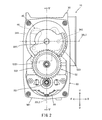
- FIG. 2 is a side view of the single combustion chamber throttle body assembly shown in FIG. 1, showing a state in which a housing case cover of a valve drive mechanism housing case that houses an electric motor and a reduction mechanism is removed.
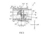
- FIG. 3 is a cross-sectional view of the single combustion chamber throttle body assembly shown in FIG. 1 cut in a direction orthogonal to the left-right direction and is a cross-sectional view taken along line III-III in FIG. 4.
- FIG. 4 is a sectional view taken along line IV-IV in FIG. 3.
- FIG. 5 is a sectional view taken along line VV in FIG. 2.
- Position of a single throttle valve, intake state detection board unit, and electric valve drive mechanism when the intake state detection board unit and electric valve drive mechanism are integrated to the left or right of a single throttle valve It is a schematic diagram which shows a relationship. Position of a single throttle valve, intake state detection board unit, and electric valve drive mechanism when the intake state detection board unit and electric valve drive mechanism are integrated to the left or right of a single throttle valve It is a schematic diagram which shows a relationship and is a schematic diagram which shows the case different from FIG. Positions of a single throttle valve, intake state detection board unit, and electric valve drive mechanism when the intake state detection board unit and the electric valve drive mechanism are distributed to the left and right of a single throttle valve It is a schematic diagram which shows a relationship.
- FIG. 3 is a schematic diagram showing the relationship and the positional relationship between the sensor connector of the intake state detection board unit and the motor connector of the electric valve drive mechanism.
- FIG. 6 is a cross-sectional view showing a relationship between a rotatable range of a single throttle valve and a sensor hole.
- FIG. 1 is a perspective view of a single combustion chamber throttle body assembly 10.
- FIG. 2 is a side view of the single combustion chamber throttle body assembly 10, showing a state in which the housing case cover 562 of the valve drive mechanism housing case 56 housing the electric motor 54 and the speed reduction mechanism 52 is removed. Is.
- the single combustion chamber throttle body assembly 10 is used, for example, in a saddle type vehicle.
- the saddle type vehicle is a vehicle including a saddle type seat.
- the saddle type vehicle includes, for example, at least one front wheel and at least one rear wheel. That is, the straddle-type vehicle is not limited to a two-wheeled vehicle, and may be a three-wheeled vehicle in which front wheels or rear wheels are composed of a pair of left and right wheels, or a front wheel and a rear wheel are each composed of a pair of left and right wheels. It may be a wheel car.
- the saddle riding type vehicle may be, for example, a tilting vehicle.
- a leaning vehicle is a vehicle that includes a leaning body that leans to the left of the vehicle when turning left and leans to the right of the vehicle when turning right.
- the single combustion chamber throttle body assembly 10 includes a single throttle valve 20, a single throttle body main body 30, an intake state detection board unit 40, and an electric valve drive mechanism 50. These will be described below.
- the left-right direction LR of the single combustion chamber throttle body assembly 10 is defined as the direction in which the rotation center axis 20C of the single throttle valve 20 included in the single combustion chamber throttle body assembly 10 extends.
- a front-rear direction FB of the single combustion chamber throttle body assembly 10 extends in a direction in which a single air passage 32 formed by a single throttle body body 30 included in the single combustion chamber throttle body assembly 10 extends; That is, it is defined as the direction in which the single throttle body body 30 extends.
- the vertical direction UD of the single combustion chamber throttle body assembly 10 is defined as a direction orthogonal to each of the front-back direction FB and the left-right direction LR.
- the direction of travel is defined as the forward direction F of the single combustion chamber throttle body assembly.
- the single combustion chamber throttle body assembly 10 is provided with a single air flow passage 32 formed by a single throttle body body 30 in a direction from downstream to upstream. It is defined as backward direction B.
- the single combustion chamber throttle body assembly 10 is moved in the forward direction F.
- the direction from right to left as viewed in is defined as the left direction L.
- the single combustion chamber throttle body assembly 10 is moved in the forward direction F.
- the direction from the left to the right when viewed at is defined as the right direction R.
- the direction from the bottom to the top when the single combustion chamber throttle body assembly 10 is viewed in the front direction F is defined as the upward direction U.
- the direction from the top to the bottom when the single combustion chamber throttle body assembly 10 is viewed in the front direction F is defined as the downward direction D.
- the axis or member extending in the front-rear direction does not necessarily indicate only the axis or member parallel to the front-rear direction.
- the axis line or member extending in the front-rear direction includes a shaft or member inclined in the range of ⁇ 45 ° with respect to the front-rear direction.
- the axis line or member extending in the vertical direction includes the axis line or member inclined in the range of ⁇ 45 ° with respect to the vertical direction.
- the axis line or the member extending in the left-right direction includes the axis line or the member inclined in the range of ⁇ 45 ° with respect to the left-right direction.
- first member and second member mean members that constitute a single combustion chamber throttle body assembly 10.
- the first member and the second member arranged in the front-rear direction indicate the following states.
- both the first member and the second member are arranged on an arbitrary straight line indicating the front-back direction.
- the first member and the second member arranged in the front-rear direction when viewed upward or downward indicate the following states.
- both the first member and the second member are arranged on an arbitrary straight line indicating the front-back direction.
- one of the first member and the second member is arranged on an arbitrary straight line indicating the front-back direction. It does not have to be done.
- the first member and the second member may be in contact with each other.
- the first member and the second member may be separated.
- a third member may be present between the first member and the second member. This definition applies to directions other than the front-back direction.
- the first member being arranged in front of the second member means the following state.
- the first member is arranged in front of a plane that passes through the front end of the second member and is orthogonal to the front-rear direction.
- the first member and the second member may or may not be arranged in the front-rear direction. This definition applies to directions other than the front-back direction.
- the first member being arranged in front of the second member means the following state. At least a part of the first member is disposed in an area through which the second member passes when moving in the forward direction. Therefore, the first member may be contained in a region through which the second member passes when moving in the forward direction, or may protrude from a region through which the second member passes when moving in the forward direction. Is also good. In this case, the first member and the second member are arranged in the front-rear direction. This definition applies to directions other than the front-back direction.
- the first member being arranged in front of the second member as viewed in the leftward or rightward direction means the following state.
- the first member and the second member are aligned in the front-rear direction when viewed in the left or right direction, and the portion of the first member facing the second member is the second member when viewed in the left or right direction. It is arranged in front of the member.
- the first member and the second member do not have to be arranged in the front-rear direction in three dimensions. This definition applies to directions other than the front-back direction.
- the first member means a member that constitutes a single combustion chamber throttle body assembly 10.
- the front part of the first member means the front half of the first member.
- the rear part of the first member means the rear half of the first member.
- the left part of the first member means the left half of the first member.
- the right part of the first member means the right half of the first member.
- the upper part of the first member means the upper half of the first member.
- the lower part of the first member means the lower half of the first member.
- the front end of the first member refers to the front end of the first member.
- the rear end of the first member means the rear end of the first member.
- the left end of the first member means the left end of the first member.
- the right end of the first member means the right end of the first member.
- the upper end of the first member means the upper end of the first member.
- the lower end of the first member means a lower end of the first member.
- the front end of the first member means the front end of the first member and its vicinity.
- the rear end of the first member means the rear end of the first member and its vicinity.
- the left end of the first member means the left end of the first member and its vicinity.
- the right end of the first member means the right end of the first member and its vicinity.
- the upper end of the first member means the upper end of the first member and its vicinity.
- the lower end of the first member means the lower end of the first member and its vicinity.
- the intake state detection board unit 40 and the electric valve drive mechanism 50 which are a plurality of electric components, are arranged on the left side of the single throttle valve 20. It is not concentrated to the right or to the right, but is distributed to the left and right of the single throttle valve 20.
- the configuration of such a single combustion chamber throttle body assembly 10 will be described below.
- the single combustion chamber throttle body assembly 10 is a throttle pulley for rotating the single throttle valve 20, and does not include a throttle pulley to which a throttle wire is connected.
- a single throttle valve 20 regulates the amount of air taken into a single combustion chamber.
- the single combustion chamber is formed in, for example, an engine provided in a saddle type vehicle in which the single combustion chamber throttle body assembly 10 is mounted.
- the engine may be a single cylinder or a V type two cylinder engine. If the engine is a V-cylinder engine, a single combustion chamber throttle body assembly 10 is arranged for each cylinder. The details of the single throttle valve 20 will be described later.
- the single throttle body body 30 forms a single air flow path 32.
- the single air flow path 32 is connected to a single combustion chamber.
- the single throttle body body 30 has a cylindrical shape.
- the central axis of the single throttle body body 30 (a front-rear direction reference line 32L1 described later) extends in the front-rear direction FB.
- the single throttle body main body 30 forms a single air flow passage 32 by utilizing the space formed inside thereof.
- a single throttle valve 20 is arranged in the single air passage 32.
- FIGS. 3 and 4 are cross-sectional views taken in a direction orthogonal to the left-right direction LR and is a cross-sectional view taken along the line III-III in FIG.
- FIG. 4 is a sectional view taken along line IV-IV in FIG.
- the single throttle valve 20 has a rotation center axis line 20C.
- the rotation center axis 20C extends in the left-right direction LR.
- the single throttle valve 20 is attached to the single throttle body main body 30 so as to be rotatable around the rotation center axis line 20C.
- the single throttle valve 20 is housed in the single throttle body main body 30. That is, the single throttle valve 20 is arranged in the single air passage 32 formed inside the single throttle body body 30.
- the single throttle valve 20 contributes to the adjustment of the amount of air flowing through the single air flow passage 32 formed inside the single throttle body main body 30.
- the single throttle valve 20 is arranged in the forward direction F or the backward direction B with respect to the flow passage cross section of the single air flow passage 32 formed inside the single throttle body body 30. It contributes to the adjustment of the proportion occupied by the single throttle valve 20 when viewed.
- the flow passage cross section means a region inside the single throttle body main body 30 when the single throttle body main body 30 forming the air flow passage 32 is cut in a direction orthogonal to the front-rear direction FB ( That is, the opening portion of the single throttle body main body 30 on the cut surface).
- the shape of the single throttle valve 20 has a shape corresponding to the shape of the flow passage cross section of the single air flow passage 32 formed inside the single throttle body main body 30.
- the flow passage cross section of the single air flow passage 32 formed inside the single throttle body main body 30 is circular. Therefore, the single throttle valve 20 has a disc shape.
- the single combustion chamber throttle body assembly 10 further includes a valve rotation support shaft 24.
- a single throttle valve 20 is fixed to the valve rotation support shaft 24.
- a screw or the like is used.
- the valve rotation support shaft 24 is attached to a single throttle body body 30 so as to cross the air flow path 32 in the left-right direction LR.
- the valve rotation support shaft 24 is attached to a single throttle body main body 30 in a state of being rotatable about its central axis.
- the central axis of the valve rotation support shaft 24 coincides with the rotation center axis 20C. That is, the valve rotation support shaft 24 is attached to the single throttle body body 30 in a state of being rotatable about the rotation center axis line 20C.
- the valve rotation support shaft 24 rotates about its center axis (that is, the rotation center axis 20C), so that the single throttle valve 20 rotates about the rotation center axis 20C. That is, the valve rotation support shaft 24 supports the single throttle valve 20 in a rotatable state about the rotation center axis line 20C.
- Both ends of the valve rotation support shaft 24 are supported so as to be rotatable about a rotation center axis 20C with respect to a single throttle body body 30. That is, both ends of the valve rotation support shaft 24 are located outside the air flow path 32 in the left-right direction LR.
- the single throttle valve 20 rotates around the rotation center axis 20C.
- the single throttle valve 20 is formed inside the single throttle body main body 30 at a position (a fully closed position P1) that closes the single air flow passage 32 formed inside the single throttle body main body 30.
- the single air flow path 32 is rotated between it and the most open position (fully open position P2). That is, when the single throttle valve 20 opens the single air passage 32 formed inside the single throttle body main body 30, the single throttle valve 20 moves from the fully closed position P1 to the fully open position P2.
- the single throttle valve 20 moves from the fully open position P2 to the fully closed position P2. It rotates in the direction toward P1.
- the intake state detection board unit 40 will be described with reference to FIG.
- the intake state detection board unit 40 detects the state of the air flowing through the single air flow path 32.
- the intake state detection board unit 40 includes two intake state detection sensors 42, an intake state detection sensor circuit board 44, and an intake state detection sensor circuit board housing case 46. Note that, in FIG. 4, the illustration of the cover of the intake state detection sensor circuit board housing case 46 is omitted.
- Each of the two intake state detection sensors 42 detects the state of the air flowing through the single air flow path 32, and outputs an electric signal according to its content.
- an intake pressure sensor 421 and an intake temperature sensor 422 are adopted as the two intake state detection sensors 42.
- the intake pressure sensor 421 detects the pressure of the air flowing through the single air flow path 32.
- the intake air temperature sensor 422 detects the temperature of the air flowing through the single air flow path 32. The details of the intake pressure sensor 421 and the intake temperature sensor 422 will be described later.
- An intake pressure sensor 421 and an intake temperature sensor 422 are connected to the intake state detection sensor circuit board 44.
- the intake pressure sensor 421 and the intake temperature sensor 422 are each connected to the intake state detection sensor circuit board 44 via a conductive member such as wiring.
- the intake state detection sensor circuit board accommodating case 46 accommodates the intake pressure sensor 421, the intake temperature sensor 422, and the intake state detection sensor circuit board 44. In this state, the intake pressure sensor 421, the intake temperature sensor 422, and the intake state detection sensor circuit board 44 are supported by the intake state detection sensor circuit board housing case 46. Specifically, it is as follows.
- a sensor housing hole 461 is formed in the intake state detection sensor circuit board housing case 46.
- the sensor housing hole 461 extends in the left-right direction LR.
- the sensor housing hole 461 is formed to penetrate the intake state detection sensor circuit board housing case 46 in the left-right direction LR. That is, the sensor housing hole 461 is opened in each of the left direction L and the right direction R.
- a partition plate 48 and an intake pressure sensor 421 are fitted in the sensor housing hole 461.
- the partition plate 48 is located closer to the single throttle body body 30 than the intake pressure sensor 421 in the left-right direction LR.
- An air hole 481 is formed in the partition plate 48.
- the air hole 481 is formed at a position overlapping with the central portion of the intake pressure sensor 421 when viewed in the right direction R.
- a sensor chip (not shown) for detecting the pressure of the air flowing through the air flow path 32 is provided at the center of the intake pressure sensor 421.
- a sensor support cylinder 462 is formed in the intake state detection sensor circuit board housing case 46.
- the sensor support cylinder 462 extends in the left-right direction LR.
- the sensor support cylinder 462 is located closer to the single throttle body body 30 than the intake pressure sensor 421 in the left-right direction LR.
- the sensor support cylinder 462 supports the sensor chip 4221 included in the intake air temperature sensor 422. More specifically, the sensor chip 4221 of the intake air temperature sensor 422 is supported at the tip of the sensor support cylinder 462.
- the intake state detection sensor circuit board 44 is supported in the intake state detection sensor circuit board storage case 46 by, for example, at least one support portion (not shown) formed in the intake state detection sensor circuit board storage case 46.
- the support portion is, for example, a protrusion that is inserted into a support hole (not shown) formed in the intake state detection sensor circuit board 44 to support the intake state detection sensor circuit board 44.
- Such an intake state detection sensor circuit board housing case 46 is fixed to a single throttle body body 30. Specifically, the intake state detection sensor circuit board housing case 46 is fixed to a pedestal 31 (see FIG. 1) provided on the outer peripheral surface of a single throttle body body 30.
- the intake pressure sensor 421 and the intake state detection sensor circuit board 44 are located to the right of the single throttle valve 20 in the left-right direction LR. In other words, the intake pressure sensor 421 and the intake state detection sensor circuit board 44 are farther from the air passage 32 than the right end of the single throttle valve 20 in the left-right direction LR. Further, in the present embodiment, the intake pressure sensor 421 and the intake state detection sensor circuit board 44 respectively have an air flow in the left-right direction LR that is higher than the right end of the valve rotation support shaft 24 to which the single throttle valve 20 is fixed. Away from the road 32.
- the intake pressure sensor 421 has a single central portion.
- the entire intake pressure sensor hole 341 as a sensor hole formed in the throttle body body 30 overlaps.
- the intake pressure sensor hole 341 is formed to the right of the single throttle valve 20 when viewed in the front direction F or the rear direction B.
- the intake pressure sensor hole 341 extends in the left-right direction LR and communicates with a single air passage 32 formed inside the single throttle body body 30. That is, the intake pressure sensor hole 341 is opened in each of the inner peripheral surface and the outer peripheral surface of the single throttle body main body 30.
- the intake pressure sensor 421 detects the pressure of the air flowing through the single air passage 32 formed inside the single throttle body body 30 via the intake pressure sensor 341 and the air hole 481. be able to. That is, the intake pressure sensor hole 341 is formed in the single throttle body main body 30 so that the intake pressure sensor 421 detects the pressure of the air flowing through the single air passage 32.
- the intake state detection sensor circuit board housing case 46 When the intake state detection sensor circuit board housing case 46 is fixed to the single throttle body body 30, it is arranged between the intake state detection sensor circuit board housing case 46 and the single throttle body body 30.
- the seal member is compressed in the left-right direction LR. Thereby, the sealing property between the intake state detection sensor circuit board housing case 46 and the single throttle body body 30 is secured.
- the intake pressure sensor 421 detects the pressure of the air flowing through the single air passage 32 formed inside the single throttle body body 30 through the intake pressure sensor hole 341 and the air hole 481. Can be accurately detected.
- the sensor support cylinder 462 that supports the sensor chip 4221 of the intake temperature sensor 422 is connected to the single throttle body main body 30. Is inserted in the intake air temperature sensor hole 342 as a sensor hole formed in the.
- the intake air temperature sensor hole 342 is formed to the right of the single throttle valve 20 when viewed in the front direction F or the rear direction B.
- the intake air temperature sensor hole 342 extends in the left-right direction LR and communicates with a single air passage 32 formed inside the single throttle body body 30. That is, the intake air temperature sensor hole 342 is opened on each of the inner peripheral surface and the outer peripheral surface of the single throttle body main body 30.
- the tip end of the sensor support cylinder 462, that is, the portion of the sensor support cylinder 462 that supports the sensor chip 4221 of the intake air temperature sensor 422, is Located on road 32.
- the tip portion of the sensor support cylinder 462 is located inside the single throttle body body 30.
- the sensor chip 4221 of the intake air temperature sensor 422 is located in the air flow path 32. Accordingly, the intake air temperature sensor 422 can detect the temperature of the air flowing through the single air flow passage 32 formed inside the single throttle body body 30.
- the intake air temperature sensor hole 342 is formed in the single throttle body body 30 so that the intake air temperature sensor 422 detects the pressure of the air flowing through the single air passage 32.
- the intake temperature sensor hole 342 is larger than the intake pressure sensor hole 341 when viewed in the left direction L or the right direction R.
- the intake pressure sensor hole 341 is viewed in the left direction L or the right direction R, and the intake state detection sensor circuit board housing case 46 and an electric valve drive described later. It overlaps with the valve drive mechanism housing case 56 of the mechanism 50. That is, when viewed in the upward direction U or the downward direction D, the intake pressure sensor hole 341 is different from the intake state detection sensor circuit board accommodating case 46 and the valve drive mechanism accommodating case 56 included in the electric valve drive mechanism 50 described later. And are formed at positions overlapping in the left-right direction LR.
- the intake air temperature sensor hole 342 overlaps with the intake state detection sensor circuit board 44 and the valve drive mechanism housing case 56 of the electric valve drive mechanism 50 described later when viewed in the left direction L or the right direction R. . That is, when viewed in the upward direction U or the downward direction D, the intake pressure sensor hole 342 is located on the left and right with respect to the valve drive mechanism housing case 56 of the intake state detection sensor circuit board 44 and the electric valve drive mechanism 50 described later. It is formed at a position overlapping in the direction LR.
- the intake pressure sensor hole 341 and the intake temperature sensor hole 342 are viewed in the left direction L or the right direction R, respectively, and the intake state detection sensor circuit board housing case 46 and the electric valve drive mechanism 50 to be described later. Overlaps with the valve drive mechanism housing case 56 included in. In other words, the intake pressure sensor hole 341 and the intake temperature sensor hole 342 are viewed in the left direction L or the right direction R, respectively, and the intake state detection board unit 40 and the electric valve drive mechanism 50 are shown. Overlap with.
- the intake state detection sensor circuit board housing case 46 has the protrusion 463 located on the central axis of the valve rotation support shaft 24 to which the single throttle valve 20 is fixed.
- An IC (not shown) forming a throttle opening sensor for detecting the opening of a single throttle valve 20 is arranged on the protrusion 463.
- the IC is, for example, a Hall element.
- the IC detects that the magnetic field formed by a magnet (not shown) that constitutes the throttle opening sensor changes with the rotation of the valve rotation support shaft 24, that is, with the rotation of a single throttle valve 20. .
- the magnet is rotatably arranged together with the valve rotation support shaft 24, and is located around the protrusion 463.
- the intake pressure sensor hole 341 is located downstream of the intake temperature sensor hole 342.
- the intake pressure sensor hole 341 is located downstream of the rotation center axis 20C of the single throttle valve 20. That is, the intake pressure sensor 421 detects the pressure of the air that flows through the air flow path 32 and that flows downstream of the rotation center axis line 20C of the single throttle valve 20.
- the intake air temperature sensor hole 342 is located upstream of the rotation center axis 20C of the single throttle valve 20. That is, the intake air temperature sensor 422 detects the temperature of the air that flows through the air flow path 32 and that flows upstream of the rotation center axis line 20C of the single throttle valve 20.
- a straight line that passes through the rotation center axis line 20C of the single throttle valve 20 and extends in the front-rear direction FB is defined as the front-rear direction reference line 32L1.
- a straight line orthogonal to the front-rear direction reference line 32L1 when viewed in the left direction L or the right direction R is defined as a vertical direction reference line 32L2.
- the intake pressure sensor hole 341 and the intake temperature sensor hole 342 are separated in the vertical direction UD.
- the intake pressure sensor hole 341 is located above the intake temperature sensor hole 342.
- the intake pressure sensor hole 341 is located above the front-rear direction reference line 32L1.
- the intake air temperature sensor hole 342 overlaps with the front-rear direction reference line 32L1.
- the center of the intake air temperature sensor hole 342 is located on the front-rear direction reference line 32L1 when viewed in the left direction L or the right direction R.
- the vertical reference line 32L2 from the center of the intake air temperature sensor hole 342, that is, the vertical reference line 32L2 from the center of the intake temperature sensor hole 342 in the front-rear direction FB. Is shorter than the distance D2 (see FIG. 3). That is, when viewed in the left direction L or the right direction R, the center of the intake pressure sensor hole 341 is located closer to the vertical reference line 32L2 than the center of the intake temperature sensor hole 342 in the front-rear direction FB. .
- the intake air pressure sensor hole 341 and the intake air temperature sensor hole 342 have a single throttle valve 20 when the single throttle valve 20 rotates around the rotation center axis 20C when viewed in the left direction or the right direction, respectively. It overlaps with the rotatable range A1 (hatched area in the single air flow path 32 shown in FIG. 3).
- FIG. 5 is a sectional view taken along line VV in FIG.
- the electric motor 54 is not shown in FIG.
- the electric valve drive mechanism 50 rotates the single throttle valve 20 around the rotation center axis 20C by being supplied with electric power.
- the electric valve drive mechanism 50 includes a speed reduction mechanism 52, an electric motor 54, and a valve drive mechanism housing case 56.
- the speed reduction mechanism 52 transmits the output of the electric motor 54 to the single throttle valve 20.
- the speed reduction mechanism 52 is mechanically connected to the single throttle valve 20.
- the electric motor 54 is mechanically connected to the reduction mechanism 52.
- the electric motor 54 receives the supply of electric power to rotate the single throttle valve 20 around the rotation center axis 20C via the speed reduction mechanism 52.
- the reduction mechanism 52 is a reduction gear train composed of a plurality of gears.
- the rotation center axes of the plurality of gears forming the reduction gear train are parallel to each other.
- the rotation center axis of each of the plurality of gears forming the reduction gear train extends in the left-right direction LR. That is, the rotation center axis of each of the plurality of gears forming the reduction gear train is parallel to the rotation center axis 20C of the single throttle valve 20.
- the reduction mechanism 52 includes an output gear 521, a transmission gear 522, and an output gear 523. These will be described below.
- the output gear 521 is fixed to the output shaft of the electric motor 54.
- the output gear 521 rotates together with the output shaft of the electric motor 54 when the electric motor 54 receives power supply.
- the rotation center axis of the output gear 521 is parallel to the rotation center axis 20C of the single throttle valve 20.
- the transmission gear 522 includes a large gear 5221 and a small gear 5222.
- the large gear 5221 and the small gear 5222 are arranged coaxially.
- the transmission gear 522 is rotatably arranged with respect to the shaft 53 supported by the valve drive mechanism housing case 56.
- the rotation center axis of the transmission gear 522 is parallel to the rotation center axis 20C of the single throttle valve 20.
- the large gear 5221 included in the transmission gear 522 meshes with the output gear 521. As a result, the rotation of the output gear 521 is transmitted to the transmission gear 522.
- the output gear 523 is fixed to the single throttle valve 20. Specifically, the output gear 523 is fixed to the single throttle valve 20 via the valve rotation support shaft 24. The output gear 523 is fixed to the left end of the valve rotation support shaft 24 to which the single throttle valve 20 is fixed. That is, the rotation center axis of the output gear 523 coincides with the rotation center axis 20C of the single throttle valve 20. The output gear 523 meshes with the pinion gear 5222 of the transmission gear 522. As a result, the rotation of the transmission gear 522 is transmitted to the output gear 523. As a result, the single throttle valve 20 to which the output gear 523 is fixed rotates about the rotation center axis 20C.
- the output gear 523 has teeth that mesh with the teeth of the small gear 5222 of the transmission gear 522 within a range necessary for the single throttle valve 20 to move between the fully closed position P1 and the fully open position P2. Are formed. That is, the teeth of the output gear 523 are not formed over the entire circumference in the circumferential direction around the rotation center axis of the output gear 523.
- the output gear 523 overlaps the entire intake air temperature sensor hole 342. It should be noted that the output gear 523 may not overlap the entire intake air temperature sensor hole 342 when viewed in the left direction L or the right direction R over the entire rotatable range of the output gear 523. The output gear 523 may overlap at least a part of the intake air temperature sensor hole 342 when viewed in the left direction L or the right direction R in at least a part of the rotatable range of the output gear 523. The output gear 523 may not overlap the intake air temperature sensor hole 342 when viewed in the left direction L or the right direction R.
- the output gear 523 overlaps a part of the intake pressure sensor hole 341.
- the output gear 523 may not overlap a part of the intake pressure sensor hole 341 when viewed in the left direction L or the right direction R over the entire rotatable range of the output gear 523.
- the output gear 523 may overlap at least a part of the intake pressure sensor hole 341 when viewed in the left direction L or the right direction R in at least a part of the rotatable range of the output gear 523.
- the output gear 523 may not overlap the intake pressure sensor hole 341 when viewed in the left direction L or the right direction R.
- the rotation center axis of the output gear 521 (the rotation center axis of the output shaft of the electric motor 54), the rotation center axis of the transmission gear 522, and the output gear 523.
- the rotation center axis line of (the rotation center axis line 20C of the single throttle valve 20) is aligned in the up-down direction UD. More specifically, when viewed in the left direction L or the right direction R, the rotation center axis of the output gear 521 (the rotation center axis of the output shaft of the electric motor 54), the rotation center axis of the transmission gear 522, and the output gear 523.
- the rotation center axis line of the single throttle valve 20 (the rotation center axis line 20C of the single throttle valve 20) are located on a straight line extending in the up-down direction UD (the up-down direction reference line 32L2).
- the valve drive mechanism housing case 56 houses the speed reduction mechanism 52 and the single electric motor 54.
- the valve drive mechanism accommodating case 56 overlaps the intake state detection sensor circuit board accommodating case 46 when viewed in the left direction L or the right direction R.
- the valve drive mechanism housing case 56 is larger than the intake state detection sensor circuit board housing case 46 when viewed in the left direction L or the right direction R.
- the intake state detection sensor circuit board housing case 46 is smaller than the valve drive mechanism housing case 56 when viewed in the left direction L or the right direction R. Therefore, when viewed in the left direction L or the right direction R, the entire intake state detection sensor circuit board housing case 46 overlaps the valve drive mechanism housing case 56.
- the valve drive mechanism housing case 56 includes a housing case body 561 and a housing case cover 562. These will be described below.
- the housing case body 561 is integrally formed with the single throttle body body 30. In this state, the housing case main body 561 opens toward the left direction L.
- the accommodation case cover 562 is attached to the accommodation case main body 561. In this state, the housing case cover 562 covers the opening of the housing case body 561. As a result, an accommodation space for accommodating the reduction mechanism 52 and the electric motor 54 is formed between the accommodation case main body 561 and the accommodation case cover 562. That is, the valve drive mechanism housing case 56 houses the reduction mechanism 52 and the electric motor 54.
- the reduction mechanism 52 is arranged to the left of the single throttle valve 20 in the left-right direction LR. Further, the electric motor 54 is located below the single air passage 32 formed inside the single throttle body main body 30 in the up-down direction UD.
- the housing case cover 562 has the protrusion 5621 located on the rotation center axis of the output gear 523.
- An IC 571 forming a throttle opening sensor 57 for detecting the opening of a single throttle valve 20 is arranged on the protrusion 5621.
- the IC 571 is, for example, a Hall element.
- the IC 571 detects that the magnetic field formed by the magnet 572 forming the throttle opening sensor 57 changes with the rotation of the output gear 523, that is, with the rotation of the single throttle valve 20.
- the magnet 572 is rotatably arranged together with the output gear 523, and is located around the protrusion 5621.
- throttle opening sensor 57 arranged to the left of the single throttle valve 20 is shown, but as is clear from the above description, the single throttle valve 20 is not shown. Throttle opening sensors are distributed and arranged on the left and right sides.
- the reduction mechanism 52 is arranged to the left of the single throttle valve 20 in the left-right direction LR, and the intake state detection sensor circuit board 44 is arranged in the left-right direction LR. Is arranged to the right of the single throttle valve 20. That is, in the single combustion chamber throttle body assembly 10, the intake state detection board unit 40 and the electric valve drive mechanism 50, which are a plurality of electric components, are provided to the left or right of the single throttle valve 20. Instead of aggregating, they are distributed to the left and right of the single throttle valve 20. As a result, the size of the single combustion chamber throttle body assembly 10, in particular, the size in at least one of the left-right direction LR and the front-back direction FB can be made compact. Specifically, it is as follows.
- FIG. 6 shows a case where the electric valve drive mechanism 50 and the intake state detection board unit 40 are collectively arranged on the right side of the single throttle valve 20, and the electric valve drive mechanism 50 is in the intake state.
- FIG. 6 is a schematic view showing a case where the detection board unit 40 is arranged closer to a single throttle valve 20.
- FIG. 7 shows a case where the electric valve drive mechanism 50 and the intake state detection board unit 40 are collectively arranged on the right side of a single throttle valve 20, and the intake state detection board unit 40 is electrically operated.
- FIG. 6 is a schematic view showing a case where the valve drive mechanism 50 is arranged closer to a single throttle valve 20.
- the speed reduction mechanism 52 included in the electric valve drive mechanism 50 is provided. It is necessary to avoid the formation of the sensor holes (the intake pressure sensor hole 341 and the intake temperature sensor hole 342). Therefore, in the single combustion chamber throttle body assembly, the length in the direction in which the single air passage 32 formed by the single throttle body main body 30 extends (the front-rear direction FB) becomes large.
- the reduction mechanism 52 is a member that is driven by transmitting the driving force of the electric motor 54, that is, a movable member.
- the intake state detection sensor (the intake pressure sensor 421 and the intake temperature sensor 422) and the intake state detection sensor circuit board 44 included in the intake state detection board unit 40 do not transmit the driving force, and thus the members that do not move, , A non-movable member.
- Such a movable member and a non-movable member need to be arranged at distant positions in order to avoid interference.
- the single throttle valve 20 is rotatably supported.
- the valve rotation support shaft 24 is disposed so as to penetrate the intake state detection sensor circuit board 44 of the intake state detection board unit 40. That is, the intake state detection sensor circuit board 44 is formed with a through hole into which the valve rotation support shaft 24 is inserted. By forming the through holes, the area of the intake state detection sensor circuit board 44 is reduced.
- the intake state detection sensor circuit board 44 is elongated in the front-back direction FB. In this case, the length of the single combustion chamber throttle body assembly 10 in the front-rear direction FB becomes large.
- the electric valve drive mechanism 50 and the intake state detection board unit 40 which are a plurality of electric parts, are integrated, the size of the single combustion chamber throttle body assembly becomes large, and the single combustion chamber throttle is assembled. It is difficult to make the size of the body assembly compact.
- the intake state detection board unit 40 which is a plurality of electric parts, and the electric type
- the valve drive mechanism 50 of FIG. 8 is distributed to the left and right of the single throttle valve 20 instead of being integrated to the left or right of the single throttle valve 20 as shown in FIG. did.
- the size of the single combustion chamber throttle body assembly 10 in particular, the size in at least one of the left-right direction LR and the front-back direction FB can be made compact. Specifically, it is as follows.
- the intake state detection board unit 40 and the electric valve drive mechanism 50 which are a plurality of electric components, are not integrated to the left or right of the single throttle valve 20, but to the left of the single throttle valve 20. And the rightward distribution improves the degree of freedom in designing the intake state detection board unit 40 and the electric valve drive mechanism 50 in the left-right direction LR.
- the degree of freedom in design of the side surface of the intake state detection board unit 40 close to the single throttle valve 20 is improved.
- the intake state detection board unit 40 can be arranged closer to the single throttle valve 20 in the left-right direction LR. That is, the size of the single combustion chamber throttle body assembly 10 in the left-right direction LR can be made compact.
- the intake state detection board unit 40 and the electric valve drive mechanism 50 which are a plurality of electric components, are not integrated in the left or right side of the single throttle valve 20, but in the single throttle valve 20.
- the sensor holes (the intake pressure sensor hole 341 and the intake temperature sensor hole 342) are formed so as to avoid the speed reduction mechanism 52 included in the electric valve drive mechanism 50. There is no need. Therefore, the positions of the sensor holes (the intake pressure sensor hole 341 and the intake temperature sensor hole 342) can be freely set. That is, the degree of freedom in designing the sensor holes (the intake pressure sensor hole 341 and the intake temperature sensor hole 342) is improved.
- the intake pressure sensor hole 341 overlaps with each of the intake state detection sensor circuit board housing case 46 and the valve drive mechanism housing case 56
- the intake air temperature sensor hole 342 overlaps with each of the intake state detection sensor circuit board 44 and the valve drive mechanism housing case 56.
- the intake state detection board unit 40 and the electric valve drive mechanism 50 which are a plurality of electric components, are not integrated to the left or right of the single throttle valve 20, but to the single throttle valve 20.
- the electric valve drive mechanism 50 which is a movable member
- the intake state detection sensor circuit board 44 which is a non-movable member, of the intake state detection board unit 40. It is not necessary to form a clearance (clearance in the left-right direction LR) for avoiding interference with the intake state detection sensor (the intake pressure sensor 421 and the intake temperature sensor 422). As a result, the size of the single combustion chamber throttle body assembly 10 in the left-right direction LR can be made compact.
- the flow passage cross section of the single air flow passage 32 is circular. Therefore, the single air flow passage 32 is arranged in the single air flow passage 32 as compared with the case where the flow passage cross section is horizontally long (that is, the left-right direction LR is longer than the up-down direction UD).
- the size of the single throttle valve 20 in the left-right direction LR can be reduced. As a result, the size of the single combustion chamber throttle body assembly 10 in the left-right direction LR can be reduced.
- the intake pressure sensor hole 341 is overlapped with the intake state detection sensor circuit board housing case 46 when viewed in the left direction L or the right direction R. Therefore, the intake pressure sensor hole 341 can be brought closer to the front-rear direction FB with respect to the rotation center axis line 20C of the single throttle valve 20. Therefore, the size of the single combustion chamber throttle body assembly 10 in the front-rear direction FB can be reduced.
- the intake state detection sensor circuit board housing case 46 is smaller than the valve drive mechanism housing case 56 when viewed in the left direction L or the right direction R. Therefore, for example, when the single combustion chamber throttle body assembly 10 is mounted on a saddle-ride type vehicle, it is possible to suppress the intake state detection sensor circuit board housing case 46 from interfering with other members.
- the intake pressure sensor hole 341 and the intake temperature sensor hole 342 are formed when the single throttle valve 20 rotates around the rotation center axis 20C when viewed in the left direction L or the right direction R, respectively.
- the single throttle valve 20 of No. 1 overlaps the rotatable range A1. Therefore, the intake pressure sensor hole 341 and the intake temperature sensor hole 342 can be brought closer to the front-back direction FB with respect to the rotation center axis line 20C of the single throttle valve 20. Therefore, the size of the single combustion chamber throttle body assembly 10 in the front-rear direction FB can be reduced.
- FIG. 9 shows a single throttle valve 20 and an intake state detection substrate unit 40 when the intake state detection substrate unit 40 and the electric valve drive mechanism 50 are distributed to the left and right of the single throttle valve 20.
- 6 is a schematic diagram showing a positional relationship with an electric valve drive mechanism 50 and a positional relationship between a connector 49 of the intake state detection board unit 40 and a connector 58 of the electric valve drive mechanism 50.
- FIG. Although not shown in FIG.
- the intake state detection sensor circuit board 44 of the intake state detection board unit 40 is not shown in the description of the above-described embodiment, but the intake state detection sensor circuit board 44 of the single throttle valve 20 in the left-right direction LR. It is arranged on the right side, and the speed reduction mechanism 52 of the electric valve drive mechanism 50 is arranged on the left side of the single throttle valve 20 in the left-right direction LR.
- the intake state detection board unit 40 further includes a connector 49 as a sensor connector. Sensor wiring (not shown) for operating the intake state detection sensor (the intake pressure sensor 421 and the intake temperature sensor 422) is connected to the connector 49.
- the connector 49 is provided in the intake state detection sensor circuit board housing case 46, for example.
- the connector 49 is arranged so as to allow the sensor wiring to be inserted and connected in the rearward direction B. That is, the connector 49 is formed so as to open in the front direction F.
- the intake state detection sensor circuit board 44 is arranged to the right of the single throttle valve 20 in the left-right direction LR. Therefore, the connector 49 is arranged to the right of the single throttle valve 20 in the left-right direction LR.
- the electric valve drive mechanism 50 further includes a connector 58 as a motor connector. Motor wiring (not shown) for driving the electric motor 54 is connected to the connector 58.
- the connector 58 is provided in the valve drive mechanism housing case 56, for example.
- the connector 58 is arranged so as to allow the motor wiring to be inserted and connected in the front direction F. That is, the connector 58 is formed so as to open in the rear direction B. In other words, the connector 58 is formed so as to open in a direction different from that of the connector 49. The connector 58 may be formed to open in the same direction as the connector 49.
- the speed reduction mechanism 52 of the electric valve drive mechanism 50 is arranged to the left of the single throttle valve 20 in the left-right direction LR. Therefore, the connector 58 is arranged to the left of the single throttle valve 20 in the left-right direction LR.
- the connector 58 and the connector 49 can be arranged dispersedly to the left and right of the single throttle valve 20. Therefore, the motor wiring (not shown) connected to the connector 58 and the sensor wiring (not shown) connected to the connector 49 can be arranged compactly. The reason is as follows.
- the number of connector pins of each of the connector 58 and the connector 49 is the same as when the connector 58 and the connector 49 are combined into one. Compared to less. Therefore, the wiring connected to each of the connector 58 and the connector 49 becomes thin. The thinner the wire, the easier it is to bend. Therefore, it is possible to make a compact arrangement.
- the speed reduction mechanism 52 is arranged to the right of the single throttle valve 20 in the left-right direction LR, and the intake state detection sensor circuit board 44 is arranged to the left of the single throttle valve 20 in the left-right direction LR.
- the motor connector (connector 58) is arranged to the right of the single throttle valve 20 in the left-right direction LR, and the sensor connector (connector 49) is located to the left of the single throttle valve 20 in the left-right direction LR. May be located at.
- the intake air temperature sensor hole 342 overlaps with each of the intake state detection sensor circuit board 44 and the valve drive mechanism housing case 56 when viewed in the left direction L or the right direction R.
- the hole 341 may overlap with each of the intake state detection sensor circuit board 44 and the valve drive mechanism housing case 56.
- the intake pressure sensor hole 341 and the intake temperature sensor hole 342 may overlap the intake state detection sensor circuit board 44 and the valve drive mechanism housing case 56, respectively. Good.
- the reduction mechanism 52 is arranged to the left of the single throttle valve 20 in the left-right direction LR, and the intake state detection sensor circuit board 44 is arranged to the right of the single throttle valve 20 in the left-right direction LR.
- the reduction mechanism 52 is arranged to the right of the single throttle valve 20 in the left-right direction LR, and the intake state detection sensor circuit board 44 is arranged to the left of the single throttle valve 20 in the left-right direction LR. May be.
- the intake pressure sensor hole 341 and the intake temperature sensor hole 342 are located to the left of the single throttle valve 20 in the left-right direction LR.
- the intake air temperature sensor hole 342 overlaps with each of the intake state detection sensor circuit board 44 and the valve drive mechanism housing case 56.
- the intake pressure sensor hole 341 may overlap with each of the intake state detection sensor circuit board 44 and the valve drive mechanism housing case 56 when viewed in the left direction L or the right direction R.
- the intake pressure sensor hole 341 and the intake temperature sensor hole 342 may overlap the intake state detection sensor circuit board 44 and the valve drive mechanism housing case 56, respectively. Good.
- the positional relationship between the intake pressure sensor 421 and the intake temperature sensor 422 is not limited to the positional relationship described in the above embodiment.
- the intake pressure sensor 421 when viewed in the left direction L or the right direction R, the intake pressure sensor 421 may be located on the front-rear direction reference line 32L1 and the intake air temperature sensor 422 may not be located on the front-rear direction reference line 32L1.
- each of the intake pressure sensor 421 and the intake temperature sensor 422 may be located on the front-rear direction reference line 32L1.
- each of the intake pressure sensor 421 and the intake temperature sensor 422 may not be located on the front-rear direction reference line 32L1.
- each of the intake pressure sensor 421 and the intake temperature sensor 422 may be located above the front-rear direction reference line 32L1, or may be located above the front-rear direction reference line 32L1. May be located below.
- one of the intake pressure sensor 421 and the intake temperature sensor 422 is located above the front-rear direction reference line 32L1, and the other of the intake pressure sensor 421 and the intake temperature sensor 422 is in the front-rear direction. It may be located below the direction reference line 32L1.
- the intake pressure sensor 421 may be located upstream of the vertical reference line 32L2.
- the intake air temperature sensor 422 may be located downstream of the vertical reference line 32L2.
- each of the intake pressure sensor 421 and the intake temperature sensor 422 may be located upstream of the vertical reference line 32L2.
- each of the intake pressure sensor 421 and the intake temperature sensor 422 may be located downstream of the vertical reference line 32L2.
- the present invention includes the case where one intake state detection sensor is provided and three or more intake state detection sensors are provided. Of course, even when the intake state detection sensor is provided, it is applicable. When only one intake state detection sensor is provided, the intake state detection sensor may be the intake pressure sensor 421 or the intake temperature sensor 422.
- the sensor hole does not have to overlap the rotatable range A1 of the single throttle valve 20 when viewed in the left direction L or the right direction R.
- the intake pressure sensor hole 341 and the intake temperature sensor hole 342 are formed downstream of the vertical reference line 32L2, and when viewed in the left direction L or the right direction R, they are It does not have to overlap the rotatable range A1 of one throttle valve 20.
- the electric motor 54 when viewed in the front direction F or the rear direction B, the electric motor 54 is positioned below the single air flow passage 32 formed inside the single throttle body body 30.
- the electric motor 54 may be located above the single air passage 32 formed inside the single throttle body body 30 when viewed in the front direction F or the rear direction B. .
- the intake pressure sensor hole 341 and the intake temperature sensor hole 342 each overlap the intake state detection sensor circuit board housing case 46.
- at least one of the intake pressure sensor hole 341 and the intake temperature sensor hole 342 may not overlap the intake state detection sensor circuit board housing case 46 when viewed in the left direction L or the right direction R.
- the entire intake state detection sensor circuit board housing case 46 overlaps the valve drive mechanism housing case 56.
- a part of the case 46 may protrude from the valve drive mechanism housing case 56 when viewed in the left direction L or the right direction R.
- each of the intake pressure sensor 421 and the intake temperature sensor 422 when viewed in the left direction L or the right direction R, is overlapped with the range A1 in which the single throttle valve 20 is rotatable at least in part.
- each of the intake pressure sensor 421 and the intake temperature sensor 422 may not overlap the range A1.
- only either the intake pressure sensor 421 or the intake temperature sensor 422 may overlap the range A1.
- the throttle opening sensors are arranged on the left side and the right side of the single throttle valve 20 in a distributed manner.
- the throttle opening sensor is arranged on either the left side or the right side of the single throttle valve 20.
- the opening sensors may be collectively arranged.
- two ICs forming the throttle opening sensor are arranged together.
- a common magnet is placed around the two ICs.
Landscapes
- Engineering & Computer Science (AREA)
- Chemical & Material Sciences (AREA)
- Combustion & Propulsion (AREA)
- Mechanical Engineering (AREA)
- General Engineering & Computer Science (AREA)
- Control Of Throttle Valves Provided In The Intake System Or In The Exhaust System (AREA)
- Combined Controls Of Internal Combustion Engines (AREA)
Abstract
単一の燃焼室に接続される単一の空気流路を形成する単一のスロットルボディ本体と、単一の空気流路に配置され、単一の燃焼室に吸入される空気の量を調整する単一のスロットルバルブと、単一のスロットルバルブを駆動するための機構である電動式のバルブ駆動機構と、単一の空気流路を流れる空気の状態を検出するための吸気状態検出基板ユニットとを備える単一の燃焼室用スロットルボディアセンブリのサイズをコンパクトにする。減速機構は左右方向において単一のスロットルバルブの右方(又は左方)に配置され、吸気状態検出センサ回路基板は左右方向において単一のスロットルバルブの左方(又は右方)に配置される。1つ又は複数のセンサ用孔のうちの少なくとも1つのセンサ用孔は、左方向又は右方向に見て、吸気状態検出センサ回路基板収容ケース及びバルブ駆動機構収容ケースの各々に重なる。
Description
本発明は、単一の燃焼室に接続される単一の空気流路と、当該単一の空気流路に配置される単一のスロットルバルブとを備えた単一の燃焼室用スロットルボディアセンブリに関する。
従来、鞍乗型車両に搭載されるスロットルボディアセンブリとして、単一の燃焼室に接続される単一の空気流路を備える単一の燃焼室用スロットルボディアセンブリが知られている。このような単一の燃焼室用スロットルボディアセンブリは、単一のスロットルボディ本体と、単一のスロットルバルブとを備えている。単一のスロットルボディ本体は、単一の燃焼室に接続される単一の空気流路を形成する。単一のスロットルバルブは、単一の空気流路に配置され、単一の燃焼室に吸入される空気の量を調整する。
ここで、鞍乗型車両は、四輪自動車と比べて、コンパクトな車体を備えている。そのため、鞍乗型車両に搭載されるスロットルボディアセンブリは、四輪自動車に搭載されるスロットルボディアセンブリと比べて、エンジンの近くに配置される。つまり、上記単一の燃焼室用スロットルボディアセンブリは、エンジンの近くに配置される。そのため、エンジン本体(例えば、シリンダ)やエアクリーナ等との干渉を避けるために、単一の燃焼室用スロットルボディアセンブリのサイズを小さくすることが求められている。
また、単一の燃焼室用スロットルボディアセンブリには、単一の空気流路を流れる空気の状態を検出するための吸気状態検出基板ユニットを備えるものが知られている。吸気状態検出基板ユニットは、単一の空気流路を流れる空気の状態を検出する吸気状態検出センサと、当該吸気状態検出センサが接続される基板とを含む。吸気状態検出センサは、例えば、単一の空気流路を流れる空気の圧力を検出する吸気圧センサや、単一の空気流路を流れる空気の温度を検出する吸気温センサである。
吸気状態検出基板ユニットが複数の吸気状態検出センサを含む場合、複数の吸気状態検出センサは、基板に対して直接或いは配線を介して接続されることにより、基板或いはその近傍に集約して配置される。複数の吸気状態検出センサは、例えば、単一の空気流路を流れる空気の圧力を検出する吸気圧センサと、単一の空気流路を流れる空気の温度を検出する吸気温センサとを含む。
このような吸気状態検出基板ユニットを備える単一の燃焼室用スロットルボディアセンブリにおいては、複数の吸気状態検出センサを基板或いはその近傍に集約して配置することで、単一の燃焼室用スロットルボディアセンブリへの要求(つまり、単一の燃焼室用スロットルボディアセンブリのサイズの小型化)を満たしている。別の表現をすれば、複数の電気部品を集約することで、単一の燃焼室用スロットルボディアセンブリの小型化を実現している。
このような当業者の技術思想は、例えば、国際公開第2005/038223号や、国際公開第2004/074661号、特許第6313405号公報、特開2014-181646号公報、特開2007-118868号公報等に開示されている。
国際公開第2005/038223号に記載の吸気装置は、スロットルボディと、センサユニットとを備える。センサユニットは、スロットルボディに搭載される。センサユニットは、複数の電気部品である吸気温センサと圧力センサとを備える。センサユニットは、圧力センサが実装される基板をさらに備える。
国際公開第2004/074661号に記載のスロットル装置は、センサモジュールユニットを備える。センサモジュールユニットは、内燃機関における燃料供給制御と吸気流量制御に必要な複数の電気部品である複数のセンサを一体的に装着したものである。複数のセンサは、吸気温度センサと、吸気圧力センサとを含む。また、センサモジュールユニットは、回路基板を備える。回路基板には、吸気圧力センサが取り付けられているとともに、吸気温度センサからのリード線が取り付けられている。
特許第6313405号公報に記載のスロットルバルブ装置は、ボディと、ボディに対して回転自在に支持されるシャフトと、シャフトに固定されボディの吸気通路に設けられるバルブと、ボディの側部に設けられたセンサユニットとを含む。センサユニットは、複数のセンサを収納する。複数のセンサは、複数の電気部品である吸気圧センサ及び吸気温センサを含む。センサユニットは、基板を含む。基板には、吸気圧センサ及び吸気温センサが接続されている。
特開2014-181646号公報に記載の吸気装置は、吸気道を有するスロットルボディと、吸気道を開閉するスロットル弁と、スロットルボディに取り付けられるセンサユニットとを備える。センサユニットは、吸気道の吸気温度を検出する吸気温センサと、吸気道の吸気圧を検出する吸気圧センサとを含む。また、センサユニットは、基板をさらに含む。基板には、複数の電気部品である吸気温センサ及び吸気圧センサが接続されている。
特開2007-118868号公報には、傾斜センサ一体モジュールが一体的に設けられたスロットルボディが開示されている。傾斜センサ一体モジュールは、吸気管に生じる負圧を検出する吸気圧センサと、吸気管の略中央における吸気温度を検出する吸気温度センサとを備える。傾斜センサ一体モジュールは、基板をさらに備える。複数の電気部品である吸気圧センサ及び吸気温度センサは、配線を介して基板に接続されている。
上記公報に記載の吸気状態検出基板ユニットを備える単一の燃焼室用スロットルボディアセンブリは、単一のスロットルバルブをワイヤによって駆動する機構を備えている。このようなワイヤ式のバルブ駆動機構を電動式のバルブ駆動機構に変更することが考えられる。電動式のバルブ駆動機構は、電力が供給されることで駆動する電気モータと、当該電気モータの駆動力をスロットルバルブに伝達する減速機構とを含む。
ここで、電動式のバルブ駆動機構は、電力が供給されることで駆動する電気モータを含むので、電気部品である。また、吸気状態検出基板ユニットは、吸気状態検出センサを含むので、電気部品である。
そのため、当業者であれば、上記のような技術思想、つまり、複数の電気部品を集約するという技術思想に従って、複数の電気部品である電動式のバルブ駆動機構と吸気状態検出基板ユニットを集約すると考えられる。しかしながら、複数の電気部品である電動式のバルブ駆動機構と吸気状態検出基板ユニットを集約すると、単一の燃焼室用スロットルボディアセンブリのサイズをコンパクトにすることが難しいことが判明した。
本発明の目的は、単一の燃焼室に接続される単一の空気流路を形成する単一のスロットルボディ本体と、単一の空気流路に配置され、単一の燃焼室に吸入される空気の量を調整する単一のスロットルバルブと、単一のスロットルバルブを駆動するための機構である電動式のバルブ駆動機構と、単一の空気流路を流れる空気の状態を検出するための吸気状態検出基板ユニットとを備える単一の燃焼室用スロットルボディアセンブリであって、そのサイズをコンパクトにすることができる単一の燃焼室用スロットルボディアセンブリを提供することである。
本願の発明者等は、単一の燃焼室に接続される単一の空気流路を形成する単一のスロットルボディ本体と、単一の空気流路に配置され、単一の燃焼室に吸入される空気の量を調整する単一のスロットルバルブと、単一のスロットルバルブを駆動するための機構であるバルブ駆動機構と、単一の空気流路を流れる空気の状態を検出するための吸気状態検出基板ユニットとを備える単一の燃焼室用スロットルボディアセンブリにおいて、バルブ駆動機構をワイヤ式から電動式に変更することを考えた。
ここで、電動式のバルブ駆動機構は、電力が供給されることで駆動する電気モータと、当該電気モータの駆動力をスロットルバルブに伝達する減速機構とを含む。つまり、電動式のバルブ駆動機構は、電気部品である。
また、単一の空気流路を流れる空気の状態を検出するための吸気状態検出基板ユニットは、単一の空気流路を流れる空気の状態を検出する吸気状態検出センサを含む。吸気状態検出センサは、電気部品である。つまり、吸気状態検出基板ユニットも、電気部品である。
したがって、単一の燃焼室に接続される単一の空気流路を形成する単一のスロットルボディ本体と、単一の空気流路に配置され、単一の燃焼室に吸入される空気の量を調整する単一のスロットルバルブと、単一のスロットルバルブを駆動するための機構であるバルブ駆動機構と、単一の空気流路を流れる空気の状態を検出するための吸気状態検出基板ユニットとを備える単一の燃焼室用スロットルボディアセンブリにおいて、バルブ駆動機構をワイヤ式から電動式に変更する場合、単一の燃焼室用スロットルボディアセンブリは、複数の電動部品を含むことになる。
そのため、当業者であれば、複数の電気部品を集約するという技術思想に従って、複数の電気部品である電動式のバルブ駆動機構と吸気状態検出基板ユニットを集約すると考えられる。そこで、本発明者等も、このような技術思想に従って、複数の電気部品である電動式のバルブ駆動機構と吸気状態検出基板ユニットを集約することについて検討した。具体的には、以下のとおりである。
単一のスロットルバルブの回転中心軸線が延びる方向を左右方向とし、電動式のバルブ駆動機構と吸気状態検出基板ユニットとを単一のスロットルバルブの左方又は右方に集約して配置する態様について検討した。具体的には、(1)電動式のバルブ駆動機構を吸気状態検出基板ユニットよりも単一のスロットルバルブの近くに配置する態様と、(2)吸気状態検出基板ユニットを電動式のバルブ駆動機構よりも単一のスロットルバルブの近くに配置する態様について検討した。
ここで、吸気状態検出センサが単一の空気流路を流れる空気の状態を検出するためには、単一のスロットルボディ本体が形成する単一の空気流路に連通するセンサ用孔を単一のスロットルボディ本体に形成する必要がある。本発明者等は、このようなセンサ用孔と電動式のバルブ駆動機構と吸気状態検出基板ユニットとの位置関係に着目して、上記(1)及び(2)の態様について検討した。その結果、以下の知見を得るに至った。
(1)の態様では、電動式のバルブ駆動機構が吸気状態検出基板ユニットよりも単一のスロットルバルブの近くに配置されるので、電動式のバルブ駆動機構が備える減速機構を避けてセンサ用孔を形成する必要がある。そのため、単一の燃焼室用スロットルボディアセンブリは、単一のスロットルボディ本体が形成する単一の空気流路が延びる方向である前後方向の長さが大きくなる。
また、減速機構は、電気モータの駆動力が伝達されることで駆動される部材、つまり、可動部材である。これに対して、吸気状態検出基板ユニットが備える吸気状態検出センサ及び基板は、駆動力が伝達されないので、動かない部材、つまり、非可動部材である。このような可動部材と非可動部材は、干渉を避けるために、離れた位置に配置する必要がある。
(1)の態様では、電動式のバルブ駆動機構と吸気状態検出基板ユニットとが単一のスロットルバルブの左方又は右方に集約して配置されているので、電動式のバルブ駆動機構が備える減速機構と吸気状態検出基板ユニットが備える基板及び吸気状態検出センサとの干渉を回避するために、電動式のバルブ駆動機構と吸気状態検出基板ユニットを左右方向に離す必要がある。そのため、単一の燃焼室用スロットルボディアセンブリの左右方向の長さが大きくなる。
(2)の態様では、上記と同様の理由により、単一の燃焼室用スロットルボディアセンブリの左右方向の長さが大きくなる。
また、(2)の態様では、吸気状態検出基板ユニットが電動式のバルブ駆動機構よりも単一のスロットルバルブの近くに配置されるので、スロットルバルブを回転可能に支持するバルブ回転支持軸が、吸気状態検出基板ユニットの基板を貫通して配置される。つまり、基板には、バルブ回転支持軸が挿入されるための貫通孔が形成される。貫通孔が形成されることで、基板の面積が減少する。基板の面積を確保するために、例えば、基板が前後方向に長くなる。この場合、単一の燃焼室用スロットルボディアセンブリの前後方向の長さが大きくなる。
したがって、複数の電気部品を集約するという技術思想に従って、電動式のバルブ駆動機構と吸気状態検出基板ユニットを集約すると、単一の燃焼室用スロットルボディアセンブリのサイズが大きくなってしまい、単一の燃焼室用スロットルボディアセンブリのサイズをコンパクトにすることが難しいことが判明した。
そこで、本願の発明者等は、複数の電気部品を集約するという技術思想に従って、複数の電気部品である電動式のバルブ駆動機構と吸気状態検出基板ユニットを集約するのではなく、他の観点から単一の燃焼室用スロットルボディアセンブリのサイズをコンパクトにすることについて検討した。具体的には、単一の燃焼室用スロットルボディアセンブリが備える単一のスロットルバルブのサイズに着目して検討した。その結果、以下の知見を得るに至った。
単一の燃焼室用スロットルボディアセンブリが備える単一のスロットルバルブは、元々サイズが小さい。そのため、電動式のバルブ駆動機構が備える減速機構は、単一の燃焼室用スロットルボディアセンブリの前後方向、つまり、単一の空気流路が延びる方向、及び、単一の燃焼室用スロットルボディアセンブリの上下方向、つまり、単一の空気流路が延びる方向に垂直な方向であって、かつ、単一のスロットルバルブの回転中心軸線が延びる方向に垂直な方向の少なくとも一方において、スロットルバルブよりも大きい。別の表現をすると、スロットルバルブは、単一の燃焼室用スロットルボディアセンブリの前後方向及び上下方向の少なくとも一方において、電動式のバルブ駆動機構が備える減速機構よりも小さい。同様に、吸気状態検出基板ユニットや当該吸気状態検出基板ユニットが備える基板も単一の燃焼室用スロットルボディアセンブリの前後方向及び上下方向の少なくとも一方において吸気状態検出基板ユニットよりも大きくなる可能性がある。
このような知見に基づいて、本願の発明者等はさらに検討を進めた。そして、複数の電気部品である吸気状態検出基板ユニットと電動式のバルブ駆動機構を、単一のスロットルバルブの左方又は右方に集約するのではなく、単一のスロットルバルブの左方及び右方に分散させることにより、単一の燃焼室用スロットルボディアセンブリの左右方向のサイズをコンパクトにすることができることに気付いた。具体的には、以下のとおりである。
複数の電気部品である吸気状態検出基板ユニットと電動式のバルブ駆動機構を、単一のスロットルバルブの左方又は右方に集約するのではなく、単一のスロットルバルブの左方及び右方に分散させることにより、吸気状態検出基板ユニットと電動式のバルブ駆動機構の左右方向の設計自由度が向上する。例えば、前方向又は後方向に見て、吸気状態検出基板ユニットの表面のうち単一のスロットルバルブに近い側面の設計自由度が向上する。その結果、吸気状態検出基板ユニットを単一のスロットルバルブに対して左右方向に近づけて配置することができる。つまり、単一の燃焼室用スロットルボディアセンブリの左右方向のサイズをコンパクトにすることができる。
このような知見は、単一の燃焼室用スロットルボディアセンブリの特徴である「単一のスロットルバルブのサイズが小さい」ということを利用して、複数の電気部品である吸気状態検出基板ユニットと電動式のバルブ駆動機構を、単一のスロットルバルブの左方又は右方に集約するのではなく、単一のスロットルバルブの左方及び右方に分散させることにより、初めて得られたものである。
また、複数の電気部品である吸気状態検出基板ユニットと電動式のバルブ駆動機構を、単一のスロットルバルブの左方又は右方に集約するのではなく、単一のスロットルバルブの左方及び右方に分散させることにより、電動式のバルブ駆動機構が備える減速機構を回避するようにしてセンサ用孔を形成する必要がなくなる。そのため、センサ用孔の位置を自由に設定することができる。つまり、センサ用孔についての設計自由度が向上する。その結果、単一の燃焼室用スロットルボディアセンブリの前後方向のサイズをコンパクトにすることができる。
加えて、複数の電気部品である吸気状態検出基板ユニットと電動式のバルブ駆動機構を、単一のスロットルバルブの左方又は右方に集約するのではなく、単一のスロットルバルブの左方及び右方に分散させることにより、電動式のバルブ駆動機構が備える可動部材である減速機構と吸気状態検出基板ユニットが備える非可動部材である基板及び吸気状態検出センサとの干渉を回避するためのクリアランス(左右方向のクリアランス)を形成する必要がなくなる。その結果、単一の燃焼室用スロットルボディアセンブリの左右方向のサイズをコンパクトにすることができる。
以上のように、複数の電気部品である吸気状態検出基板ユニットと電動式のバルブ駆動機構を、単一のスロットルバルブの左方又は右方に集約するのではなく、単一のスロットルバルブの左方及び右方に分散させることにより、単一の燃焼室用スロットルボディアセンブリのサイズ、特に、左右方向及び前後方向の少なくとも一方のサイズをコンパクトにすることができる。本発明は、このような知見に基づいて完成されたものである。
本発明の一実施形態に係る単一の燃焼室用スロットルボディアセンブリは、単一のスロットルバルブと、単一のスロットルボディ本体とを備える。単一のスロットルバルブは、単一の燃焼室に吸入される空気量を調整し、その回転中心軸線回りに回転可能なものである。単一のスロットルボディ本体は、単一の燃焼室に接続され、単一のスロットルバルブが配置される単一の空気流路を形成する。単一の燃焼室用スロットルボディアセンブリは、吸気状態検出基板ユニットと、電動式のバルブ駆動機構とを備える。吸気状態検出基板ユニットは、単一の空気流路を流れる空気の状態を検出する。電動式のバルブ駆動機構は、電力の供給を受けることにより、単一のスロットルバルブを回転中心軸線回りに回転させる。吸気状態検出基板ユニットは、1つ又は複数の吸気状態検出センサと、吸気状態検出センサ回路基板と、吸気状態検出センサ回路基板収容ケースとを含む。吸気状態検出センサは、単一の空気流路を流れる空気の状態を検出する。吸気状態検出センサ回路基板には、1つ又は複数の吸気状態検出センサが接続される。吸気状態検出センサ回路基板収容ケースは、吸気状態検出センサ回路基板を収容する。電動式のバルブ駆動機構は、減速機構と、電気モータと、バルブ駆動機構収容ケースとを含む。減速機構は、単一のスロットルバルブに対して機械的に接続される。電気モータは、減速機構に対して機械的に接続され、電力の供給を受けて減速機構を介して単一のスロットルバルブを回転させる。バルブ駆動機構収容ケースは、減速機構及び電気モータを収容する。単一のスロットルバルブの回転中心軸線を左右方向と平行に配置した場合、減速機構及び吸気状態検出センサ回路基板は、単一のスロットルバルブに対して、以下の(1)又は(2)を満たすように配置される。
(1)減速機構は左右方向において単一のスロットルバルブの右方に配置され、吸気状態検出センサ回路基板は左右方向において単一のスロットルバルブの左方に配置される。
(2)減速機構は左右方向において単一のスロットルバルブの左方に配置され、吸気状態検出センサ回路基板は左右方向において単一のスロットルバルブの右方に配置される。
単一のスロットルボディ本体には、1つ又は複数のセンサ用孔が形成されている。センサ用孔は、吸気状態検出センサが単一の空気流路を流れる空気の状態を検出するためのものである。1つ又は複数のセンサ用孔は、以下の(3)又は(4)を満たすような位置に存在する。
(3)減速機構及び吸気状態検出センサ回路基板が単一のスロットルバルブに対して上記(1)を満たすように配置されている場合、1つ又は複数のセンサ用孔は、左右方向において単一のスロットルバルブの左方に位置し、1つ又は複数のセンサ用孔のうちの少なくとも1つのセンサ用孔は、左方向又は右方向に見て、吸気状態検出センサ回路基板収容ケース及びバルブ駆動機構収容ケースの各々に重なる。
(4)減速機構及び吸気状態検出センサ回路基板が単一のスロットルバルブに対して上記(2)を満たすように配置されている場合、1つ又は複数のセンサ用孔は、左右方向において単一のスロットルバルブの右方に位置し、1つ又は複数のセンサ用孔のうちの少なくとも1つのセンサ用孔は、左方向又は右方向に見て、吸気状態検出センサ回路基板収容ケース及びバルブ駆動機構収容ケースの各々に重なる。
(1)減速機構は左右方向において単一のスロットルバルブの右方に配置され、吸気状態検出センサ回路基板は左右方向において単一のスロットルバルブの左方に配置される。
(2)減速機構は左右方向において単一のスロットルバルブの左方に配置され、吸気状態検出センサ回路基板は左右方向において単一のスロットルバルブの右方に配置される。
単一のスロットルボディ本体には、1つ又は複数のセンサ用孔が形成されている。センサ用孔は、吸気状態検出センサが単一の空気流路を流れる空気の状態を検出するためのものである。1つ又は複数のセンサ用孔は、以下の(3)又は(4)を満たすような位置に存在する。
(3)減速機構及び吸気状態検出センサ回路基板が単一のスロットルバルブに対して上記(1)を満たすように配置されている場合、1つ又は複数のセンサ用孔は、左右方向において単一のスロットルバルブの左方に位置し、1つ又は複数のセンサ用孔のうちの少なくとも1つのセンサ用孔は、左方向又は右方向に見て、吸気状態検出センサ回路基板収容ケース及びバルブ駆動機構収容ケースの各々に重なる。
(4)減速機構及び吸気状態検出センサ回路基板が単一のスロットルバルブに対して上記(2)を満たすように配置されている場合、1つ又は複数のセンサ用孔は、左右方向において単一のスロットルバルブの右方に位置し、1つ又は複数のセンサ用孔のうちの少なくとも1つのセンサ用孔は、左方向又は右方向に見て、吸気状態検出センサ回路基板収容ケース及びバルブ駆動機構収容ケースの各々に重なる。
上記単一の燃焼室用スロットルボディアセンブリにおいては、複数の電気部品である吸気状態検出基板ユニットと電動式のバルブ駆動機構を、単一のスロットルバルブの左方又は右方に集約するのではなく、単一のスロットルバルブの左方及び右方に分散させているので、単一の燃焼室用スロットルボディアセンブリのサイズ、特に、左右方向及び前後方向の少なくとも一方のサイズをコンパクトにすることができる。
上記単一の燃焼室用スロットルボディアセンブリにおいて、単一のスロットルバルブは、単一の燃焼室に吸入される空気量を調整し、その回転中心軸線回りに回転可能なものであれば、特に限定されない。単一のスロットルバルブの形状等は、例えば、単一のスロットルバルブが配置される単一の空気流路の流路断面の形状等に応じて、適宜、変更される。なお、流路断面とは、単一の空気流路を形成する単一のスロットルボディ本体を当該単一のスロットルボディ本体が延びる方向に対して直交する方向に切断したときの単一のスロットルボディ本体の内側の領域、つまり、当該切断面における単一のスロットルボディ本体の開口部分である。単一のスロットルバルブは、例えば、単一のスロットルボディ本体に対して回転可能に配置されたバルブ回転支持軸に固定された状態で、単一のスロットルボディ本体が形成する単一の空気流路に配置される。これにより、単一のスロットルバルブは、その回転中心軸線回りに回転可能な状態で配置される。単一のスロットルバルブによる単一の燃焼室に吸入される空気量の調整は、単一のスロットルバルブの回転中心軸線回りの回転に起因して単一の空気流路の開閉状態が変化することによって実現される。単一のスロットルバルブをバルブ回転支持軸に固定する手段は、特に限定されない。単一のスロットルバルブをバルブ回転支持軸に固定する際には、例えば、ねじ等が用いられる。
上記単一の燃焼室用スロットルボディアセンブリにおいて、単一のスロットルボディ本体は、単一の燃焼室に接続され、単一のスロットルバルブが配置される単一の空気流路を形成するものであれば、特に限定されない。単一の空気流路が単一の燃焼室に接続される態様は、特に限定されない。例えば、単一の空気流路は、当該単一の空気流路に接続される他の空気流路を介して、単一の燃焼室に接続されてもよい。単一のスロットルボディ本体の内側に形成された単一の空気流路の流路断面積は、単一のスロットルボディ本体の全長に亘って、つまり、単一のスロットルボディ本体が延びる方向の全体に亘って、一定であってもよいし、変化していてもよい。なお、流路断面積とは、空気流路を形成する単一のスロットルボディ本体を当該単一のスロットルボディ本体が延びる方向に対して直交する方向に切断したときの単一のスロットルボディ本体の内側の領域の面積、つまり、当該切断面における単一のスロットルボディ本体の開口面積である。
上記単一の燃焼室用スロットルボディアセンブリにおいて、吸気状態検出ユニットは、単一の空気流路を流れる空気の状態を検出するものであれば、特に限定されない。吸気状態検出センサは、単一の空気流路を流れる空気の状態を検出するものであれば、特に限定されない。単一の空気流路を流れる空気の状態とは、例えば、単一の空気流路を流れる空気の圧力であってもよいし、単一の空気流路を流れる空気の温度であってもよい。吸気状態検出センサは、単一のスロットルボディ本体に形成されたセンサ用孔を利用して、単一のスロットルボディ本体が形成する単一の空気流路を流れる空気の状態を検出するものであれば、特に限定されない。吸気状態検出センサがセンサ用孔を利用する態様としては、例えば、吸気状態検出センサがセンサ用孔を通じて空気流路を流れる空気の状態を検出する態様と、吸気状態検出センサの少なくとも一部がセンサ用孔に挿入された状態で空気流路を流れる空気の状態を検出する態様とがある。後者の態様において、吸気状態検出センサのうち空気流路を流れる空気の状態を検出する部分は、空気流路に存在していてもよい。
上記単一の燃焼室用スロットルボディアセンブリにおいて、センサ用孔は、単一のスロットルバルブの右方又は左方に形成されていればよい。ここで、単一のスロットルバルブの右方(左方)とは、単一のスロットルバルブの右端(左端)よりも右方(左方)に限定されない。例えば、単一のスロットルバルブが円板形状を有し、かつ、単一のスロットルバルブが全閉位置にある場合、単一のスロットルバルブの右方(左方)は、単一のスロットルバルブの左右方向の中心よりも右方(左方)であって、かつ、単一のスロットルバルブの右端(左端)よりも左方(右方)の位置でもよい。
上記単一の燃焼室用スロットルボディアセンブリにおいて、吸気状態検出センサ回路基板は、吸気状態検出センサが接続されるものであれば、特に限定されない。吸気状態検出センサが吸気状態検出センサ回路基板に接続される態様は、特に限定されない。吸気状態検出センサは、吸気状態検出センサ回路基板に対して直接的に接続されていてもよいし、間接的に接続されていてもよい。吸気状態検出センサが吸気状態検出センサ回路基板に対して直接的に接続される態様には、例えば、吸気状態検出センサが吸気状態検出センサ回路基板に実装されることが含まれる。吸気状態検出センサが吸気状態検出センサ回路基板に対して間接的に接続される態様としては、例えば、吸気状態検出センサが配線等の導電部材を介して吸気状態検出センサ回路基板に接続されることが含まれる。
上記単一の燃焼室用スロットルボディアセンブリにおいて、電動式のバルブ駆動機構は、電力の供給を受けることにより、単一のスロットルバルブを回転中心軸線回りに回転させるものであれば、特に限定されない。
上記単一の燃焼室用スロットルボディアセンブリにおいて、減速機構は、単一のスロットルバルブに対して機械的に接続されるものであれば、特に限定されない。減速機構が単一のスロットルバルブに対して機械的に接続される態様は、減速機構から単一のスロットルバルブに対して駆動力の伝達が可能な態様であれば、特に限定されない。減速機構は、単一のスロットルバルブに対して直接的に接続されていてもよいし、単一のスロットルバルブに対して間接的に接続されていてもよい。減速機構が単一のスロットルバルブに対して間接的に接続される態様には、例えば、単一のスロットルバルブを回転可能に支持するバルブ回転支持軸に対して減速機構の一部(例えば、減速機構を構成する複数の歯車の何れか)が固定されることが含まれる。減速機構は、例えば、減速歯車列である。減速歯車列は、例えば、複数の歯車を含む。複数の歯車の各々は、好ましくは、単一のスロットルバルブの回転中心軸線と平行な軸線回りに回転可能な平歯車又ははすば歯車である。これにより、減速機構において単一のスロットルバルブの回転中心軸線が延びる方向の長さを短くすることができる。
上記単一の燃焼室用スロットルボディアセンブリにおいて、電気モータは、減速機構に対して機械的に接続され、電力の供給を受けて減速機構を介して単一のスロットルバルブを回転させるものであれば、特に限定されない。電気モータが減速機構に対して機械的に接続される態様は、電気モータから減速機構に対して駆動力の伝達が可能な態様であれば、特に限定されない。電気モータは、減速機構に対して直接的に接続されていてもよいし、減速機構に対して間接的に接続されていてもよい。電気モータが減速機構に対して間接的に接続される態様には、例えば、電気モータの出力軸に対して減速機構の一部(例えば、減速機構を構成する複数の歯車の何れか)が固定されることが含まれる。
上記単一の燃焼室用スロットルボディアセンブリにおいて、バルブ駆動機構収容ケースは、減速機構及び電気モータを収容するものであれば、特に限定されない。バルブ駆動機構収容ケースは、例えば、減速機構を収容する部分と、単一の電気モータを収容する部分とを含んでいてもよい。バルブ駆動機構収容ケースは、例えば、単一のスロットルバルブの回転中心軸線が延びる方向に分割可能な構造を有していてもよい。
上記単一の燃焼室用スロットルボディアセンブリにおいて、センサ用孔が左方向又は右方向に見て吸気状態検出センサ回路基板収容ケース及びバルブ駆動機構収容ケースの各々に重なる態様には、センサ用孔の全体が左方向又は右方向に見て吸気状態検出センサ回路基板収容ケース及びバルブ駆動機構収容ケースの各々に重なる態様だけでなく、センサ用孔の一部が左方向又は右方向に見て吸気状態検出センサ回路基板収容ケース及びバルブ駆動機構収容ケースの各々に重なる態様を含む。
上記単一の燃焼室用スロットルボディアセンブリにおいて、左方向又は右方向に見たときに吸気状態検出センサ回路基板収容ケースに重なるセンサ用孔は、左方向又は右方向に見たときに吸気状態検出センサ回路基板に重なるセンサ用孔であってもよいし、左方向又は右方向に見たときに吸気状態検出センサ回路基板に重ならないセンサ用孔であってもよい。
上記単一の燃焼室用スロットルボディアセンブリにおいて、単一の空気流路の流路断面は円形であってもよい。
このような態様においては、単一の空気流路の流路断面が横長の楕円形である場合と比べて、単一の空気流路に配置される単一のスロットルバルブの左右方向のサイズを小さくすることができる。そのため、単一の燃焼室用スロットルボディアセンブリの左右方向のサイズを小さくすることができる。
なお、上記単一の燃焼室用スロットルボディアセンブリにおいて、単一の空気流路の流路断面は円形に限定されない。例えば、単一の空気流路の流路断面は楕円形等でもよい。
上記単一の燃焼室用スロットルボディアセンブリにおいて、1つ又は複数のセンサ用孔のうちの少なくとも1つのセンサ用孔は、左方向又は右方向に見て、吸気状態検出センサ回路基板に重なっていてもよい。
このような態様においては、センサ用孔を単一のスロットルバルブの回転中心軸線に対して前後方向に近づけることができる。そのため、単一の燃焼室用スロットルボディアセンブリの前後方向のサイズを小さくすることができる。
上記単一の燃焼室用スロットルボディアセンブリにおいて、吸気状態検出センサ回路基板収容ケースは、左方向又は右方向に見て、バルブ駆動機構収容ケースよりも小さくてもよい。
このような態様においては、例えば、単一の燃焼室用スロットルボディアセンブリが鞍乗型車両に搭載された状態で、吸気状態検出センサ回路基板収容ケースが他の部材と干渉するのを抑制することができる。
なお、上記単一の燃焼室用スロットルボディアセンブリにおいて、吸気状態検出センサ回路基板収容ケースは、左方向又は右方向に見て、バルブ駆動機構収容ケースよりも小さければ、特に限定されない。吸気状態検出センサ回路基板収容ケースは、左方向又は右方向に見て、その全体がバルブ駆動機構収容ケースに重なっていてもよい。或いは、吸気状態検出センサ回路基板収容ケースは、左方向又は右方向に見て、その一部がバルブ駆動機構収容ケースからはみ出していてもよい。例えば、吸気状態検出センサ回路基板収容ケースは、左方向又は右方向に見て、その前端又は後端がバルブ駆動機構収容ケースの外側に位置していてもよい。
上記単一の燃焼室用スロットルボディアセンブリにおいて、吸気状態検出基板ユニットは、センサコネクタをさらに含んでいてもよい。センサコネクタには、吸気状態検出センサを動作させるためのセンサ配線が接続される。電動式のバルブ駆動機構は、モータコネクタをさらに含んでいてもよい。モータコネクタには、電気モータを駆動するためのモータ配線が接続される。
上記態様において、減速機構が左右方向において単一のスロットルバルブの右方に配置され、かつ、吸気状態検出センサ回路基板が左右方向において単一のスロットルバルブの左方に配置される場合には、モータコネクタが左右方向において単一のスロットルバルブの右方に配置され、かつ、センサコネクタが左右方向において単一のスロットルバルブの左方に配置されてもよい。また、減速機構が左右方向において単一のスロットルバルブの左方に配置され、かつ、吸気状態検出センサ回路基板が左右方向において単一のスロットルバルブの右方に配置される場合には、モータコネクタが左右方向において単一のスロットルバルブの左方に配置され、かつ、センサコネクタが左右方向において単一のスロットルバルブの右方に配置されてもよい。
このような態様においては、モータコネクタとセンサコネクタを単一のスロットルバルブの左方及び右方に分散させて配置することができる。そのため、モータ配線及びセンサ配線をコンパクトに配策することができる。その理由は、以下のとおりである。
モータコネクタ及びセンサコネクタを1つに纏めると、コネクタピンの数が多くなる。そのため、コネクタに接続される配線が太くなる。配線が太くなると、配線を曲げることが難しくなる。そのため、コンパクトに配策することが困難になる。
これに対して、上記のようにモータコネクタ及びセンサコネクタを分散して配置する態様においては、モータコネクタ及びセンサコネクタの各々のコネクタピンの数が、モータコネクタ及びセンサコネクタを1つに纏める場合と比べて少なくなる。そのため、モータコネクタ及びセンサコネクタの各々に接続される配線が細くなる。配線が細くなると、配線を曲げやすくなる。そのため、コンパクトに配策することができる。
上記単一の燃焼室用スロットルボディアセンブリにおいて、1つ又は複数のセンサ用孔のうちの少なくとも1つのセンサ用孔は、左方向又は右方向に見て、単一のスロットルバルブが回転中心軸線回りに回転するときの単一のスロットルバルブが回転可能な範囲に重なっていてもよい。
このような態様においては、センサ用孔を単一のスロットルバルブの回転中心軸線に対して前後方向に近づけることができる。そのため、単一の燃焼室用スロットルボディアセンブリの前後方向のサイズを小さくすることができる。
上記単一の燃焼室用スロットルボディアセンブリにおいて、センサ用孔が左方向又は右方向に見て単一のスロットルバルブが回転中心軸線回りに回転するときの単一のスロットルバルブが回転可能な範囲に重なる態様には、センサ用孔の全体が左方向又は右方向に見て単一のスロットルバルブが回転中心軸線回りに回転するときの単一のスロットルバルブが回転可能な範囲に重なる態様だけでなく、センサ用孔の一部が左方向又は右方向に見て単一のスロットルバルブが回転中心軸線回りに回転するときの単一のスロットルバルブが回転可能な範囲に重なる態様が含まれる。
なお、上記単一の燃焼室用スロットルボディアセンブリにおいて、左方向又は右方向に見たときに単一のスロットルバルブが回転可能な範囲に重なるセンサ用孔は、左方向又は右方向に見たときに吸気状態検出センサ回路基板に重なるセンサ用孔であってもよいし、左方向又は右方向に見たときに吸気状態検出センサ回路基板に重ならないセンサ用孔であってもよい。
上記単一の燃焼室用スロットルボディアセンブリにおいて、1つ又は複数のセンサ用孔のうちの少なくとも1つのセンサ用孔は、左方向又は右方向に見て、単一のスロットルバルブが回転中心軸線回りに回転するときの単一のスロットルバルブが回転可能な範囲に重ならなくてもよい。
このような態様においては、例えば、吸気状態検出センサがセンサ用孔に挿し通されてその一部が空気流路内に存在する状態で使用される場合に、吸気状態検出センサと単一のスロットルバルブとの干渉を回避することができる。センサ用孔の位置についての設計自由度が向上するので、合理的な設計をすることができる。その結果、単一の燃焼室用スロットルボディアセンブリのサイズ(例えば、前後方向のサイズや、左右方向のサイズ)をコンパクトにすることができる。
この発明の上述の目的及びその他の目的、特徴、局面及び利点は、添付図面に関連して行われる以下のこの発明の実施形態の詳細な説明から一層明らかとなろう。
本明細書にて使用される場合、用語「及び/又は(and/or)」は1つの、又は複数の関連した列挙されたアイテム(items)のあらゆる又は全ての組み合わせを含む。
本明細書中で使用される場合、用語「含む、備える(including)」、「含む、備える(comprising)」又は「有する(having)」及びその変形の使用は、記載された特徴、工程、操作、要素、成分及び/又はそれらの等価物の存在を特定するが、ステップ、動作、要素、コンポーネント、及び/又はそれらのグループのうちの1つ又は複数を含むことができる。
他に定義されない限り、本明細書で使用される全ての用語(技術用語及び科学用語を含む)は、本発明が属する当業者によって一般的に理解されるのと同じ意味を有する。
一般的に使用される辞書に定義された用語のような用語は、関連する技術及び本開示の文脈における意味と一致する意味を有すると解釈されるべきであり、本明細書で明示的に定義されていない限り、理想的又は過度に形式的な意味で解釈されることはない。
本発明の説明においては、技術及び工程の数が開示されていると理解される。これらの各々は個別の利益を有し、それぞれは、他の開示された技術の1つ以上、又は、場合によっては全てと共に使用することもできる。従って、明確にするために、この説明は、不要に個々のステップの可能な組み合わせの全てを繰り返すことを控える。それにもかかわらず、明細書及び特許請求の範囲は、そのような組み合わせが全て本発明及び特許請求の範囲内にあることを理解して読まれるべきである。
以下の説明では、説明の目的で、本発明の完全な理解を提供するために多数の具体的な詳細を述べる。しかしながら、当業者には、これらの特定の詳細なしに本発明を実施できることが明らかである。本開示は、本発明の例示として考慮されるべきであり、本発明を以下の図面又は説明によって示される特定の実施形態に限定することを意図するものではない。
本発明によれば、単一の燃焼室用スロットルボディアセンブリのサイズ、特に、左右方向及び前後方向の少なくとも一方のサイズをコンパクトにすることができる。
以下、図面を参照しながら、本発明の実施の形態による単一の燃焼室用スロットルボディアセンブリの詳細について説明する。なお、以下に説明する実施の形態は、あくまでも一例である。本発明は、以下に説明する実施の形態によって、何等、限定的に解釈されるものではない。
図1及び図2を参照しながら、本発明の実施の形態による単一の燃焼室用スロットルボディアセンブリ10について説明する。図1は、単一の燃焼室用スロットルボディアセンブリ10の斜視図である。図2は、単一の燃焼室用スロットルボディアセンブリ10の側面図であって、電気モータ54及び減速機構52を収容するバルブ駆動機構収容ケース56の収容ケースカバー562を取り外した状態を示す側面図である。
単一の燃焼室用スロットルボディアセンブリ10は、例えば、鞍乗型車両に用いられる。鞍乗型車両は、サドル型のシートを備える車両である。鞍乗型車両は、例えば、少なくとも1つの前輪と、少なくとも1つの後輪とを備える。つまり、鞍乗型車両は、二輪車に限定されず、前輪又は後輪が左右一対の車輪で構成された三輪車であってもよいし、前輪及び後輪がそれぞれ左右一対の車輪で構成された四輪車であってもよい。鞍乗型車両は、例えば、傾斜車両であってもよい。傾斜車両とは、左旋回時に車両の左方向に傾斜し、右旋回時に車両の右方向に傾斜する傾斜車体を備える車両である。
単一の燃焼室用スロットルボディアセンブリ10は、単一のスロットルバルブ20と、単一のスロットルボディ本体30と、吸気状態検出基板ユニット40と、電動式のバルブ駆動機構50とを備える。以下、これらについて説明する。
なお、本明細書では、単一の燃焼室用スロットルボディアセンブリ10における各種の方向を、以下のように定義する。
単一の燃焼室用スロットルボディアセンブリ10の左右方向LRを、単一の燃焼室用スロットルボディアセンブリ10が備える単一のスロットルバルブ20の回転中心軸線20Cが延びる方向と定義する。単一の燃焼室用スロットルボディアセンブリ10の前後方向FBを、単一の燃焼室用スロットルボディアセンブリ10が備える単一のスロットルボディ本体30によって形成される単一の空気流路32が延びる方向、つまり、単一のスロットルボディ本体30が延びる方向と定義する。単一の燃焼室用スロットルボディアセンブリ10の上下方向UDを、前後方向FB及び左右方向LRの各々に直交する方向と定義する。
単一の燃焼室用スロットルボディアセンブリ10が備える単一のスロットルボディ本体30によって形成される単一の空気流路32を空気が流れる方向、つまり、単一の空気流路32の上流から下流に向かう方向を、単一の燃焼室用スロットルボディアセンブリの前方向Fと定義する。単一の燃焼室用スロットルボディアセンブリ10が備える単一のスロットルボディ本体30によって形成される単一の空気流路32の下流から上流に向かう方向を、単一の燃焼室用スロットルボディアセンブリ10の後方向Bと定義する。単一の燃焼室用スロットルボディアセンブリ10が備える単一のスロットルバルブ20の回転中心軸線20Cが延びる方向、つまり、上記左右方向LRのうち、単一の燃焼室用スロットルボディアセンブリ10を前方向Fに見て右から左に向かう方向を、左方向Lと定義する。単一の燃焼室用スロットルボディアセンブリ10が備える単一のスロットルバルブ20の回転中心軸線20Cが延びる方向、つまり、上記左右方向LRのうち、単一の燃焼室用スロットルボディアセンブリ10を前方向Fに見て左から右に向かう方向を、右方向Rと定義する。単一の燃焼室用スロットルボディアセンブリ10の上下方向UDのうち、単一の燃焼室用スロットルボディアセンブリ10を前方向Fに見て下から上に向かう方向を、上方向Uと定義する。単一の燃焼室用スロットルボディアセンブリ10の上下方向UDのうち、単一の燃焼室用スロットルボディアセンブリ10を前方向Fに見て上から下に向かう方向を、下方向Dと定義する。
本明細書において、前後方向に延びる軸線や部材は、必ずしも前後方向と平行である軸線や部材だけを示すものではない。前後方向に延びる軸線や部材とは、前後方向に対して±45°の範囲で傾斜している軸や部材を含む。同様に、上下方向に延びる軸線や部材とは、上下方向に対して±45°の範囲で傾斜している軸線や部材を含む。左右方向に延びる軸線や部材とは、左右方向に対して±45°の範囲で傾斜している軸線や部材を含む。
本明細書における任意の2つの部材を第1部材及び第2部材と定義した場合、任意の2つの部材の関係は以下のような意味になる。なお、第1部材及び第2部材は、単一の燃焼室用スロットルボディアセンブリ10を構成する部材を意味する。
本明細書において、前後方向に並ぶ第1部材及び第2部材とは、以下の状態を示す。前後方向に垂直な方向に第1部材及び第2部材を見たときに、第1部材及び第2部材の両方が前後方向を示す任意の直線上に配置されている状態である。本明細書において、上方向又は下方向に見て前後方向に並ぶ第1部材及び第2部材とは、以下の状態を示す。上方向又は下方向に第1部材及び第2部材を見たときに、第1部材及び第2部材の両方が前後方向を示す任意の直線上に配置されている。この場合、上方向及び下方向とは異なる左方向又は右方向に第1部材及び第2部材を見ると、第1部材及び第2部材の何れか一方が前後方向を示す任意の直線上に配置されていなくてもよい。なお、第1部材と第2部材とが接触していてもよい。第1部材と第2部材とが離れていてもよい。第1部材と第2部材との間に第3部材が存在していてもよい。この定義は、前後方向以外の方向にも適用される。
本明細書において、第1部材が第2部材よりも前方に配置されるとは、以下の状態を指す。第1部材は、第2部材の前端を通り前後方向に直交する平面の前方に配置される。この場合、第1部材及び第2部材は、前後方向に並んでいてもよく、並んでいなくてもよい。この定義は、前後方向以外の方向にも適用される。
本明細書において、第1部材が第2部材の前方に配置されるとは、以下の状態を指す。第1部材の少なくとも一部は、第2部材が前方向に平行移動するときに通過する領域内に配置されている。よって、第1部材は、第2部材が前方向に平行移動するときに通過する領域内に収まっていてもよいし、第2部材が前方向に平行移動するときに通過する領域から突出していてもよい。この場合、第1部材及び第2部材は、前後方向に並んでいる。この定義は、前後方向以外の方向にも適用される。
本明細書において、左方向又は右方向に見て、第1部材が第2部材の前方に配置されるとは、以下の状態を指す。左方向又は右方向に見て、第1部材と第2部材が前後方向に並んでおり、且つ、左方向又は右方向に見て、第1部材の第2部材と対向する部分が、第2部材の前方に配置される。この定義において、第1部材と第2部材は、3次元では、前後方向に並んでいなくてもよい。この定義は、前後方向以外の方向も適用される。
本明細書において、特に断りのない場合には、第1部材の各部について以下のように定義する。なお、第1部材とは、単一の燃焼室用スロットルボディアセンブリ10を構成する部材を意味する。
第1部材の前部とは、第1部材の前半分を意味する。第1部材の後部とは、第1部材の後半分を意味する。第1部材の左部とは、第1部材の左半分を意味する。第1部材の右部とは、第1部材の右半分を意味する。第1部材の上部とは、第1部材の上半分を意味する。第1部材の下部とは、第1部材の下半分を意味する。第1部材の前端とは、第1部材の前方向の端を意味する。第1部材の後端とは、第1部材の後方向の端を意味する。第1部材の左端とは、第1部材の左方向の端を意味する。第1部材の右端とは、第1部材の右方向の端を意味する。第1部材の上端とは、第1部材の上方向の端を意味する。第1部材の下端とは、第1部材の下方向の端を意味する。第1部材の前端部とは、第1部材の前端及びその近傍を意味する。第1部材の後端部とは、第1部材の後端及びその近傍を意味する。第1部材の左端部とは、第1部材の左端及びその近傍を意味する。第1部材の右端部とは、第1部材の右端及びその近傍を意味する。第1部材の上端部とは、第1部材の上端及びその近傍を意味する。第1部材の下端部とは、第1部材の下端及びその近傍を意味する。
図1に示すように、単一の燃焼室用スロットルボディアセンブリ10においては、複数の電気部品である吸気状態検出基板ユニット40と電動式のバルブ駆動機構50が、単一のスロットルバルブ20の左方又は右方に集約されておらず、単一のスロットルバルブ20の左方及び右方に分散されている。このような単一の燃焼室用スロットルボディアセンブリ10の構成について、以下に説明する。なお、単一の燃焼室用スロットルボディアセンブリ10は、単一のスロットルバルブ20を回転させるためのスロットルプーリであって、スロットルワイヤが接続されるスロットルプーリを備えていない。
単一のスロットルバルブ20は、単一の燃焼室に吸入される空気量を調整する。単一の燃焼室は、例えば、単一の燃焼室用スロットルボディアセンブリ10が搭載される鞍乗型車両に設けられたエンジンに形成されている。エンジンは、単気筒であってもよいし、V型2気筒エンジンであってもよい。エンジンがV型2気筒エンジンである場合、各々の気筒に対して単一の燃焼室用スロットルボディアセンブリ10が配置される。なお、単一のスロットルバルブ20の詳細については、後述する。
単一のスロットルボディ本体30は、単一の空気流路32を形成する。単一の空気流路32は、単一の燃焼室に接続される。
単一のスロットルボディ本体30は、円筒形状を有している。単一のスロットルボディ本体30の中心軸線(後述する前後方向基準線32L1)は、前後方向FBに延びている。単一のスロットルボディ本体30は、その内側に形成された空間を利用して、単一の空気流路32を形成している。単一の空気流路32には、単一のスロットルバルブ20が配置される。
図3及び図4を参照しながら、単一のスロットルバルブ20の詳細について説明する。図3は、左右方向LRに対して直交する方向に切断した断面図であって、図4におけるIII-III断面図である。図4は、図3におけるIV-IV断面図である。
単一のスロットルバルブ20は、回転中心軸線20Cを有している。回転中心軸線20Cは、左右方向LRに延びている。単一のスロットルバルブ20は、回転中心軸線20C回りに回転可能な状態で単一のスロットルボディ本体30に取り付けられている。
単一のスロットルバルブ20は、単一のスロットルボディ本体30に収容されている。つまり、単一のスロットルバルブ20は、単一のスロットルボディ本体30の内側に形成された単一の空気流路32に配置されている。
単一のスロットルバルブ20は、単一のスロットルボディ本体30の内側に形成された単一の空気流路32を流れる空気量の調整に寄与する。別の表現をすれば、単一のスロットルバルブ20は、単一のスロットルボディ本体30の内側に形成された単一の空気流路32の流路断面に対して前方向F又は後方向Bに見たときに単一のスロットルバルブ20が占める割合の調整に寄与する。ここで、流路断面とは、空気流路32を形成する単一のスロットルボディ本体30を前後方向FBに対して直交する方向に切断したときの単一のスロットルボディ本体30の内側の領域(つまり、当該切断面における単一のスロットルボディ本体30の開口部分)である。
単一のスロットルバルブ20の形状は、単一のスロットルボディ本体30の内側に形成された単一の空気流路32の流路断面の形状に対応した形状を有している。本実施の形態では、単一のスロットルボディ本体30の内側に形成された単一の空気流路32の流路断面は、円形である。そのため、単一のスロットルバルブ20は、円板形状を有している。
ここで、単一の燃焼室用スロットルボディアセンブリ10は、バルブ回転支持軸24をさらに備える。バルブ回転支持軸24に対して、単一のスロットルバルブ20が固定されている。単一のスロットルバルブ20をバルブ回転支持軸24に固定する際には、例えば、ねじ等が用いられる。
バルブ回転支持軸24は、空気流路32を左右方向LRに横切るようにして、単一のスロットルボディ本体30に取り付けられている。バルブ回転支持軸24は、その中心軸線回りに回転可能な状態で、単一のスロットルボディ本体30に取り付けられている。ここで、バルブ回転支持軸24の中心軸線は、回転中心軸線20Cと一致している。つまり、バルブ回転支持軸24は、回転中心軸線20C回りに回転可能な状態で、単一のスロットルボディ本体30に取り付けられている。そして、バルブ回転支持軸24がその中心軸線(つまり、回転中心軸線20C)回りに回転することで、単一のスロットルバルブ20が回転中心軸線20C回りに回転する。つまり、バルブ回転支持軸24は、単一のスロットルバルブ20を回転中心軸線20C回りに回転可能な状態で支持している。
バルブ回転支持軸24の両端部は、それぞれ、単一のスロットルボディ本体30に対して回転中心軸線20C回りに回転可能な状態で支持されている。つまり、バルブ回転支持軸24の両端部は、それぞれ、左右方向LRにおいて空気流路32の外側に位置している。
バルブ回転支持軸24が回転中心軸線20C回りに回転することにより、単一のスロットルバルブ20が回転中心軸線20C回りに回転する。単一のスロットルバルブ20は、単一のスロットルボディ本体30の内側に形成された単一の空気流路32を閉じる位置(全閉位置P1)と、単一のスロットルボディ本体30の内側に形成された単一の空気流路32を最も開いた位置(全開位置P2)との間で回転する。つまり、単一のスロットルバルブ20が単一のスロットルボディ本体30の内側に形成された単一の空気流路32を開くときには、単一のスロットルバルブ20が全閉位置P1から全開位置P2に向かう方向に回転し、単一のスロットルバルブ20が単一のスロットルボディ本体30の内側に形成された単一の空気流路32を閉じるときには、単一のスロットルバルブ20が全開位置P2から全閉位置P1に向かう方向に回転する。
図4を参照しながら、吸気状態検出基板ユニット40について説明する。吸気状態検出基板ユニット40は、単一の空気流路32を流れる空気の状態を検出する。吸気状態検出基板ユニット40は、2つの吸気状態検出センサ42と、吸気状態検出センサ回路基板44と、吸気状態検出センサ回路基板収容ケース46とを含む。なお、図4では、吸気状態検出センサ回路基板収容ケース46が有するカバーの図示は省略している。
2つの吸気状態検出センサ42は、それぞれ、単一の空気流路32を流れる空気の状態を検出し、その内容に応じた電気信号を出力する。ここで、本実施の形態では、2つの吸気状態検出センサ42として、吸気圧力センサ421と、吸気温度センサ422とが採用されている。吸気圧力センサ421は、単一の空気流路32を流れる空気の圧力を検出する。吸気温度センサ422は、単一の空気流路32を流れる空気の温度を検出する。なお、吸気圧力センサ421と吸気温度センサ422の詳細については、後述する。
吸気状態検出センサ回路基板44には、吸気圧力センサ421と吸気温度センサ422が接続されている。本実施の形態では、吸気圧力センサ421と吸気温度センサ422は、それぞれ、配線等の導電部材を介して、吸気状態検出センサ回路基板44に接続されている。
吸気状態検出センサ回路基板収容ケース46は、吸気圧力センサ421、吸気温度センサ422及び吸気状態検出センサ回路基板44を収容している。この状態で、吸気圧力センサ421、吸気温度センサ422及び吸気状態検出センサ回路基板44は、吸気状態検出センサ回路基板収容ケース46によって支持されている。具体的には、以下のとおりである。
吸気状態検出センサ回路基板収容ケース46には、センサ収容孔461が形成されている。センサ収容孔461は、左右方向LRに延びている。センサ収容孔461は、吸気状態検出センサ回路基板収容ケース46を左右方向LRに貫通するように形成されている。つまり、センサ収容孔461は、左方向L及び右方向Rの各々に開口している。
センサ収容孔461には、仕切板48と、吸気圧力センサ421とが嵌め込まれている。仕切板48は、左右方向LRにおいて吸気圧力センサ421よりも単一のスロットルボディ本体30の近くに位置している。
仕切板48には、空気孔481が形成されている。空気孔481は、右方向Rに見たときに、吸気圧力センサ421の中央部に対して重なる位置に形成されている。吸気圧力センサ421の中央部には、空気流路32を流れる空気の圧力を検出するためのセンサチップ(図示せず)が設けられている。
吸気状態検出センサ回路基板収容ケース46には、センサ支持筒462が形成されている。センサ支持筒462は、左右方向LRに延びている。センサ支持筒462は、左右方向LRにおいて吸気圧力センサ421よりも単一のスロットルボディ本体30の近くに位置している。センサ支持筒462は、吸気温度センサ422が有するセンサチップ4221を支持している。より具体的には、センサ支持筒462の先端部において、吸気温度センサ422のセンサチップ4221が支持されている。
吸気状態検出センサ回路基板44は、例えば、吸気状態検出センサ回路基板収容ケース46に形成された少なくとも1つの支持部(図示せず)によって、吸気状態検出センサ回路基板収容ケース46に支持されている。支持部は、例えば、吸気状態検出センサ回路基板44に形成された支持孔(図示せず)に挿入されて、吸気状態検出センサ回路基板44を支持する突起である。
このような吸気状態検出センサ回路基板収容ケース46は、単一のスロットルボディ本体30に固定されている。具体的には、吸気状態検出センサ回路基板収容ケース46は、単一のスロットルボディ本体30の外周面に設けられた台座31(図1参照)に固定されている。
この状態で、吸気圧力センサ421及び吸気状態検出センサ回路基板44は、それぞれ、左右方向LRにおいて、単一のスロットルバルブ20よりも右方に位置している。別の表現をすれば、吸気圧力センサ421及び吸気状態検出センサ回路基板44は、それぞれ、左右方向LRにおいて、単一のスロットルバルブ20の右端よりも空気流路32から離れている。また、本実施の形態では、吸気圧力センサ421及び吸気状態検出センサ回路基板44は、それぞれ、左右方向LRにおいて、単一のスロットルバルブ20が固定されたバルブ回転支持軸24の右端よりも空気流路32から離れている。
吸気状態検出センサ回路基板収容ケース46が単一のスロットルボディ本体30に固定された状態では、左方向L又は右方向Rに見たときに、吸気圧力センサ421の中央部には、単一のスロットルボディ本体30に形成されたセンサ用孔としての吸気圧力センサ用孔341の全体が重なる。
ここで、吸気圧力センサ用孔341は、前方向F又は後方向Bに見て、単一のスロットルバルブ20の右方に形成されている。吸気圧力センサ用孔341は、左右方向LRに延びて、単一のスロットルボディ本体30の内側に形成された単一の空気流路32に連通している。つまり、吸気圧力センサ用孔341は、単一のスロットルボディ本体30の内周面と外周面のそれぞれに開口している。
また、左方向L又は右方向Rに見たときに、空気孔481の全体が吸気圧力センサ用孔341に重なる。これにより、吸気圧力センサ421は、吸気圧力センサ用341及び空気孔481を介して、単一のスロットルボディ本体30の内側に形成された単一の空気流路32を流れる空気の圧力を検出することができる。つまり、吸気圧力センサ用孔341は、吸気圧力センサ421が単一の空気流路32を流れる空気の圧力を検出するために、単一のスロットルボディ本体30に形成されている。
なお、吸気状態検出センサ回路基板収容ケース46が単一のスロットルボディ本体30に固定された状態では、吸気状態検出センサ回路基板収容ケース46と単一のスロットルボディ本体30との間に配置されたシール部材が左右方向LRに圧縮されている。これにより、吸気状態検出センサ回路基板収容ケース46と単一のスロットルボディ本体30との間のシール性が確保される。その結果、吸気圧力センサ421は、吸気圧力センサ用孔341及び空気孔481を介して、単一のスロットルボディ本体30の内側に形成された単一の空気流路32を流れる空気の圧力をより正確に検出することができる。
また、吸気状態検出センサ回路基板収容ケース46が単一のスロットルボディ本体30に固定された状態では、吸気温度センサ422のセンサチップ4221を支持するセンサ支持筒462が、単一のスロットルボディ本体30に形成されたセンサ用孔としての吸気温度センサ用孔342に挿入されている。
ここで、吸気温度センサ用孔342は、前方向F又は後方向Bに見て、単一のスロットルバルブ20の右方に形成されている。吸気温度センサ用孔342は、左右方向LRに延びて、単一のスロットルボディ本体30の内側に形成された単一の空気流路32に連通している。つまり、吸気温度センサ用孔342は、単一のスロットルボディ本体30の内周面と外周面のそれぞれに開口している。
センサ支持筒462が吸気温度センサ用孔342に挿入された状態で、センサ支持筒462の先端部、つまり、センサ支持筒462のうち吸気温度センサ422のセンサチップ4221を支持する部分は、空気流路32に位置している。別の表現をすれば、センサ支持筒462の先端部は、単一のスロットルボディ本体30の内側に位置している。要するに、吸気温度センサ422のセンサチップ4221は、空気流路32に位置している。これにより、吸気温度センサ422は、単一のスロットルボディ本体30の内側に形成された単一の空気流路32を流れる空気の温度を検出することができる。つまり、吸気温度センサ用孔342は、吸気温度センサ422が単一の空気流路32を流れる空気の圧力を検出するために、単一のスロットルボディ本体30に形成されている。なお、本実施形態では、左方向L又は右方向Rに見て、吸気温度センサ用孔342は、吸気圧力センサ用孔341よりも大きい。
ここで、図2及び図4を参照して、吸気圧力センサ用孔341は、左方向L又は右方向Rに見て、吸気状態検出センサ回路基板収容ケース46と、後述する電動式のバルブ駆動機構50が有するバルブ駆動機構収容ケース56とに重なる。つまり、吸気圧力センサ用孔341は、上方向U又は下方向Dに見て、吸気状態検出センサ回路基板収容ケース46及び後述する電動式のバルブ駆動機構50が有するバルブ駆動機構収容ケース56に対して左右方向LRで重なる位置に形成されている。
また、吸気温度センサ用孔342は、左方向L又は右方向Rに見て、吸気状態検出センサ回路基板44と、後述する電動式のバルブ駆動機構50が有するバルブ駆動機構収容ケース56とに重なる。つまり、吸気圧力センサ用孔342は、上方向U又は下方向Dに見て、吸気状態検出センサ回路基板44及び後述する電動式のバルブ駆動機構50が有するバルブ駆動機構収容ケース56に対して左右方向LRで重なる位置に形成されている。
要するに、吸気圧力センサ用孔341と吸気温度センサ用孔342は、それぞれ、左方向L又は右方向Rに見て、吸気状態検出センサ回路基板収容ケース46と、後述する電動式のバルブ駆動機構50が有するバルブ駆動機構収容ケース56とに重なる。別の表現をすれば、吸気圧力センサ用孔341と吸気温度センサ用孔342は、それぞれ、左方向L又は右方向Rに見て、吸気状態検出基板ユニット40と、電動式のバルブ駆動機構50とに重なる。
なお、本実施の形態では、吸気状態検出センサ回路基板収容ケース46が、単一のスロットルバルブ20が固定されたバルブ回転支持軸24の中心軸線上に位置する突起463を有している。突起463には、単一のスロットルバルブ20の開度を検出するためのスロットル開度センサを構成するIC(図示せず)が配置されている。当該ICは、例えば、ホール素子である。当該ICは、スロットル開度センサを構成する磁石(図示せず)によって形成される磁場がバルブ回転支持軸24の回転、つまり、単一のスロットルバルブ20の回転に伴って変化するのを検出する。当該磁石は、バルブ回転支持軸24とともに回転可能に配置されて、突起463の周囲に位置する。
図2を参照しながら、吸気圧力センサ用孔341と吸気温度センサ用孔342との位置関係について説明する。吸気圧力センサ用孔341は、吸気温度センサ用孔342よりも下流に位置している。
ここで、吸気圧力センサ用孔341は、単一のスロットルバルブ20の回転中心軸線20Cよりも下流に位置している。つまり、吸気圧力センサ421は、空気流路32を流れる空気であって、単一のスロットルバルブ20の回転中心軸線20Cよりも下流を流れる空気の圧力を検出する。
また、吸気温度センサ用孔342は、単一のスロットルバルブ20の回転中心軸線20Cよりも上流に位置している。つまり、吸気温度センサ422は、空気流路32を流れる空気であって、単一のスロットルバルブ20の回転中心軸線20Cよりも上流を流れる空気の温度を検出する。
ここで、左方向L又は右方向Rに見て、単一のスロットルバルブ20の回転中心軸線20Cを通過し、且つ、前後方向FBに延びる直線を、前後方向基準線32L1と定義する。また、左方向L又は右方向Rに見て、前後方向基準線32L1に直交する直線を、上下方向基準線32L2と定義する。
左方向L又は右方向Rに見て、吸気圧力センサ用孔341と吸気温度センサ用孔342は、上下方向UDに離れている。左方向L又は右方向Rに見て、吸気圧力センサ用孔341は、吸気温度センサ用孔342よりも上方に位置している。左方向L又は右方向Rに見て、吸気圧力センサ用孔341は、前後方向基準線32L1よりも上方に位置している。左方向L又は右方向Rに見て、吸気温度センサ用孔342は、前後方向基準線32L1に重なる。なお、本実施の形態では、左方向L又は右方向Rに見て、吸気温度センサ用孔342の中心が前後方向基準線32L1上に位置している。
左方向L又は右方向Rに見て、吸気圧力センサ用孔341の中心から上下方向基準線32L2までの最短距離、つまり、前後方向FBにおける吸気圧力センサ用孔341の中心から上下方向基準線32L2までの距離D1(図3参照)は、吸気温度センサ用孔342の中心から上下方向基準線32L2までの最短距離、つまり、前後方向FBにおける吸気温度センサ用孔342の中心から上下方向基準線32L2までの距離D2(図3参照)よりも短い。つまり、左方向L又は右方向Rに見て、吸気圧力センサ用孔341の中心は、前後方向FBにおいて、吸気温度センサ用孔342の中心よりも上下方向基準線32L2の近くに位置している。
吸気圧力センサ用孔341及び吸気温度センサ用孔342は、それぞれ、左方向又は右方向に見て、単一のスロットルバルブ20が回転中心軸線20C回りに回転するときの単一のスロットルバルブ20が回転可能な範囲A1(図3に示す単一の空気流路32においてハッチングを付した領域)に重なる。
続いて、図2及び図5を参照しながら、電動式のバルブ駆動機構50について説明する。ここで、図5は、図2におけるV-V断面図である。なお、図5では、電気モータ54の図示は省略している。
電動式のバルブ駆動機構50は、電力の供給を受けることにより、単一のスロットルバルブ20を回転中心軸線20C回りに回転させる。電動式のバルブ駆動機構50は、減速機構52と、電気モータ54と、バルブ駆動機構収容ケース56とを含む。
減速機構52は、電気モータ54の出力を単一のスロットルバルブ20に伝達する。減速機構52は、単一のスロットルバルブ20に対して機械的に接続されている。電気モータ54は、減速機構52に対して機械的に接続されている。電気モータ54は、電力の供給を受けることにより、減速機構52を介して、単一のスロットルバルブ20を回転中心軸線20C回りに回転させる。
減速機構52は、複数の歯車からなる減速歯車列である。減速歯車列を構成する複数の歯車の各々の回転中心軸線は、互いに平行である。減速歯車列を構成する複数の歯車の各々の回転中心軸線は、左右方向LRに延びている。つまり、減速歯車列を構成する複数の歯車の各々の回転中心軸線は、単一のスロットルバルブ20の回転中心軸線20Cに平行である。
減速機構52は、出力歯車521と、伝達歯車522と、出力歯車523とを含む。以下、これらについて説明する。
出力歯車521は、電気モータ54の出力軸に固定されている。出力歯車521は、電気モータ54が電力の供給を受けることにより、電気モータ54の出力軸とともに回転する。出力歯車521の回転中心軸線は、単一のスロットルバルブ20の回転中心軸線20Cに平行である。
伝達歯車522は、大歯車5221と、小歯車5222とを含む。大歯車5221と小歯車5222は、同軸上に配置されている。伝達歯車522は、バルブ駆動機構収容ケース56によって支持された軸53に対して回転可能に配置されている。伝達歯車522の回転中心軸線は、単一のスロットルバルブ20の回転中心軸線20Cに平行である。伝達歯車522が有する大歯車5221は、出力歯車521に噛み合っている。これにより、出力歯車521の回転が伝達歯車522に伝達される。
出力歯車523は、単一のスロットルバルブ20に固定されている。具体的には、出力歯車523は、バルブ回転支持軸24を介して、単一のスロットルバルブ20に固定されている。出力歯車523は、単一のスロットルバルブ20が固定されたバルブ回転支持軸24の左端部に固定されている。つまり、出力歯車523の回転中心軸線は、単一のスロットルバルブ20の回転中心軸線20Cと一致している。出力歯車523は、伝達歯車522が有する小歯車5222に噛み合っている。これにより、伝達歯車522の回転が出力歯車523に伝達される。その結果、出力歯車523が固定された単一のスロットルバルブ20が回転中心軸線20C回りに回転する。
ここで、出力歯車523には、単一のスロットルバルブ20が全閉位置P1と全開位置P2との間を移動するのに必要な範囲で、伝達歯車522の小歯車5222が有する歯に噛み合う歯が形成されている。つまり、出力歯車523の歯は、出力歯車523の回転中心軸線回りの周方向において全周に亘って形成されていない。
図2に示す状態では、左方向L又は右方向Rに見て、出力歯車523は、吸気温度センサ用孔342の全体に重なる。なお、出力歯車523は、出力歯車523が回転可能な範囲の全体に亘って左方向L又は右方向Rに見たときに吸気温度センサ用孔342の全体に重なっていなくてもよい。出力歯車523は、出力歯車523が回転可能な範囲の少なくとも一部において左方向L又は右方向Rに見たときに吸気温度センサ用孔342の少なくとも一部に重なっていてもよい。出力歯車523は、左方向L又は右方向Rに見て、吸気温度センサ用孔342に重ならなくてもよい。
図2に示す状態では、左方向L又は右方向Rに見て、出力歯車523は、吸気圧力センサ用孔341の一部に重なる。なお、出力歯車523は、出力歯車523が回転可能な範囲の全体に亘って左方向L又は右方向Rに見たときに吸気圧力センサ用孔341の一部に重なっていなくてもよい。出力歯車523は、出力歯車523が回転可能な範囲の少なくとも一部において左方向L又は右方向Rに見たときに吸気圧力センサ用孔341の少なくとも一部に重なっていてもよい。出力歯車523は、左方向L又は右方向Rに見て、吸気圧力センサ用孔341に重ならなくてもよい。
本実施の形態では、左方向L又は右方向Rに見て、出力歯車521の回転中心軸線(電気モータ54の出力軸の回転中心軸線)と、伝達歯車522の回転中心軸線と、出力歯車523の回転中心軸線(単一のスロットルバルブ20の回転中心軸線20C)とが、上下方向UDに並んでいる。より具体的には、左方向L又は右方向Rに見て、出力歯車521の回転中心軸線(電気モータ54の出力軸の回転中心軸線)と、伝達歯車522の回転中心軸線と、出力歯車523の回転中心軸線(単一のスロットルバルブ20の回転中心軸線20C)とが、上下方向UDに延びる直線(上記の上下方向基準線32L2)上に位置している。
バルブ駆動機構収容ケース56は、減速機構52及び単一の電気モータ54を収容する。バルブ駆動機構収容ケース56は、左方向L又は右方向Rに見たときに、吸気状態検出センサ回路基板収容ケース46に重なる。ここで、バルブ駆動機構収容ケース56は、左方向L又は右方向Rに見たときに、吸気状態検出センサ回路基板収容ケース46よりも大きい。別の表現をすれば、吸気状態検出センサ回路基板収容ケース46は、左方向L又は右方向Rに見たときに、バルブ駆動機構収容ケース56よりも小さい。そのため、左方向L又は右方向Rに見たときに、吸気状態検出センサ回路基板収容ケース46の全体がバルブ駆動機構収容ケース56に重なっている。
バルブ駆動機構収容ケース56は、収容ケース本体561と、収容ケースカバー562とを含む。以下、これらについて説明する。
収容ケース本体561は、単一のスロットルボディ本体30に対して一体的に形成されている。この状態で、収容ケース本体561は、左方向Lに向かって開口している。
収容ケースカバー562は、収容ケース本体561に取り付けられる。この状態で、収容ケースカバー562は、収容ケース本体561の開口を覆っている。これにより、収容ケース本体561と収容ケースカバー562との間には、減速機構52と電気モータ54とを収容する収容空間が形成されている。つまり、バルブ駆動機構収容ケース56は、減速機構52と、電気モータ54とを収容する。
このようにして、減速機構52と電気モータ54がバルブ駆動機構収容ケース56に収容された状態で、減速機構52は、左右方向LRにおいて単一のスロットルバルブ20の左方に配置されている。また、電気モータ54は、上下方向UDにおいて、単一のスロットルボディ本体30の内側に形成される単一の空気流路32よりも下方に位置している。
なお、本実施の形態では、収容ケースカバー562が、出力歯車523の回転中心軸線上に位置する突起5621を有している。突起5621には、単一のスロットルバルブ20の開度を検出するためのスロットル開度センサ57を構成するIC571が配置されている。IC571は、例えば、ホール素子である。IC571は、スロットル開度センサ57を構成する磁石572によって形成される磁場が出力歯車523の回転、つまり、単一のスロットルバルブ20の回転に伴って変化するのを検出する。磁石572は、出力歯車523とともに回転可能に配置されて、突起5621の周囲に位置する。
なお、本実施の形態では、単一のスロットルバルブ20の左方に配置されたスロットル開度センサ57だけが図示されているが、上述の説明から明らかなように、単一のスロットルバルブ20の左方及び右方にスロットル開度センサが分散して配置されている。
上記のように、単一の燃焼室用スロットルボディアセンブリ10においては、減速機構52が左右方向LRにおいて単一のスロットルバルブ20の左方に配置され、吸気状態検出センサ回路基板44が左右方向LRにおいて単一のスロットルバルブ20の右方に配置されている。つまり、単一の燃焼室用スロットルボディアセンブリ10においては、複数の電気部品である吸気状態検出基板ユニット40と電動式のバルブ駆動機構50を、単一のスロットルバルブ20の左方又は右方に集約するのではなく、単一のスロットルバルブ20の左方及び右方に分散させている。これにより、単一の燃焼室用スロットルボディアセンブリ10のサイズ、特に、左右方向LR及び前後方向FBの少なくとも一方のサイズをコンパクトにすることができる。具体的には、以下のとおりである。
先ず、上記の効果を理解しやすくするために、複数の電気部品である電動式のバルブ駆動機構50と吸気状態検出基板ユニット40を単一のスロットルバルブ20の左方又は右方に集約する場合について、図6及び図7を参照しながら説明する。図6は、電動式のバルブ駆動機構50と吸気状態検出基板ユニット40とを単一のスロットルバルブ20の右方に集約して配置する場合であって、電動式のバルブ駆動機構50を吸気状態検出基板ユニット40よりも単一のスロットルバルブ20の近くに配置する場合を示す模式図である。図7は、電動式のバルブ駆動機構50と吸気状態検出基板ユニット40とを単一のスロットルバルブ20の右方に集約して配置する場合であって、吸気状態検出基板ユニット40を電動式のバルブ駆動機構50よりも単一のスロットルバルブ20の近くに配置する場合を示す模式図である。
図6に示す態様では、電動式のバルブ駆動機構50が吸気状態検出基板ユニット40よりも単一のスロットルバルブ20の近くに配置されるので、電動式のバルブ駆動機構50が備える減速機構52を避けてセンサ用孔(吸気圧力センサ用孔341及び吸気温度センサ用孔342)を形成する必要がある。そのため、単一の燃焼室用スロットルボディアセンブリは、単一のスロットルボディ本体30が形成する単一の空気流路32が延びる方向(前後方向FB)の長さが大きくなる。
また、減速機構52は、電気モータ54の駆動力が伝達されることで駆動される部材、つまり、可動部材である。これに対して、吸気状態検出基板ユニット40が備える吸気状態検出センサ(吸気圧力センサ421及び吸気温度センサ422)及び吸気状態検出センサ回路基板44は、駆動力が伝達されないので、動かない部材、つまり、非可動部材である。このような可動部材と非可動部材は、干渉を避けるために、離れた位置に配置する必要がある。
図6及び図7に示す態様では、それぞれ、電動式のバルブ駆動機構50と吸気状態検出基板ユニット40とが単一のスロットルバルブ20の右方に集約して配置されているので、電動式のバルブ駆動機構50が備える減速機構52と吸気状態検出基板ユニット40が備える吸気状態検出センサ(吸気圧力センサ421及び吸気温度センサ422)及び吸気状態検出センサ回路基板44との干渉を回避するために、電動式のバルブ駆動機構50と吸気状態検出基板ユニット40を左右方向LRに離す必要がある。そのため、単一の燃焼室用スロットルボディアセンブリの左右方向LRの長さが大きくなる。
また、図7に示す態様では、吸気状態検出基板ユニット40が電動式のバルブ駆動機構50よりも単一のスロットルバルブ20の近くに配置されるので、単一のスロットルバルブ20を回転可能に支持するバルブ回転支持軸24が、吸気状態検出基板ユニット40の吸気状態検出センサ回路基板44を貫通して配置される。つまり、吸気状態検出センサ回路基板44には、バルブ回転支持軸24が挿入されるための貫通孔が形成される。貫通孔が形成されることで、吸気状態検出センサ回路基板44の面積が減少する。吸気状態検出センサ回路基板44の面積を確保するために、例えば、吸気状態検出センサ回路基板44が前後方向FBに長くなる。この場合、単一の燃焼室用スロットルボディアセンブリ10の前後方向FBの長さが大きくなる。
したがって、複数の電気部品である電動式のバルブ駆動機構50と吸気状態検出基板ユニット40を集約すると、単一の燃焼室用スロットルボディアセンブリのサイズが大きくなってしまい、単一の燃焼室用スロットルボディアセンブリのサイズをコンパクトにすることが難しい。
そこで、単一の燃焼室用スロットルボディアセンブリ10の特徴である「単一のスロットルバルブ20のサイズが小さい」ということを利用して、複数の電気部品である吸気状態検出基板ユニット40と電動式のバルブ駆動機構50を、図8に示すように、単一のスロットルバルブ20の左方又は右方に集約するのではなく、単一のスロットルバルブ20の左方及び右方に分散させるようにした。これにより、単一の燃焼室用スロットルボディアセンブリ10のサイズ、特に、左右方向LR及び前後方向FBの少なくとも一方のサイズをコンパクトにすることができる。具体的には、以下のとおりである。
複数の電気部品である吸気状態検出基板ユニット40と電動式のバルブ駆動機構50を、単一のスロットルバルブ20の左方又は右方に集約するのではなく、単一のスロットルバルブ20の左方及び右方に分散させることにより、吸気状態検出基板ユニット40と電動式のバルブ駆動機構50の左右方向LRの設計自由度が向上する。例えば、前方向F又は後方向Bに見て、吸気状態検出基板ユニット40の表面のうち単一のスロットルバルブ20に近い側面の設計自由度が向上する。その結果、吸気状態検出基板ユニット40を単一のスロットルバルブ20に対して左右方向LRに近づけて配置することができる。つまり、単一の燃焼室用スロットルボディアセンブリ10の左右方向LRのサイズをコンパクトにすることができる。
また、複数の電気部品である吸気状態検出基板ユニット40と電動式のバルブ駆動機構50を、単一のスロットルバルブ20の左方又は右方に集約するのではなく、単一のスロットルバルブ20の左方及び右方に分散させることにより、電動式のバルブ駆動機構50が備える減速機構52を回避するようにしてセンサ用孔(吸気圧力センサ用孔341及び吸気温度センサ用孔342)を形成する必要がなくなる。そのため、センサ用孔(吸気圧力センサ用孔341及び吸気温度センサ用孔342)の位置を自由に設定することができる。つまり、センサ用孔(吸気圧力センサ用孔341及び吸気温度センサ用孔342)についての設計自由度が向上する。
ここで、本実施の形態では、左方向L又は右方向Rに見たときに、吸気圧力センサ用孔341が吸気状態検出センサ回路基板収容ケース46及びバルブ駆動機構収容ケース56の各々に重なり、かつ、吸気温度センサ用孔342が、吸気状態検出センサ回路基板44及びバルブ駆動機構収容ケース56の各々に重なる。その結果、単一の燃焼室用スロットルボディアセンブリ10の前後方向FBのサイズをコンパクトにすることができる。
加えて、複数の電気部品である吸気状態検出基板ユニット40と電動式のバルブ駆動機構50を、単一のスロットルバルブ20の左方又は右方に集約するのではなく、単一のスロットルバルブ20の左方及び右方に分散させることにより、電動式のバルブ駆動機構50が備える可動部材である減速機構52と吸気状態検出基板ユニット40が備える非可動部材である吸気状態検出センサ回路基板44及び吸気状態検出センサ(吸気圧力センサ421及び吸気温度センサ422)との干渉を回避するためのクリアランス(左右方向LRのクリアランス)を形成する必要がなくなる。その結果、単一の燃焼室用スロットルボディアセンブリ10の左右方向LRのサイズをコンパクトにすることができる。
本実施の形態では、単一の空気流路32の流路断面が円形である。そのため、単一の空気流路32の流路断面が横長(つまり、左右方向LRが上下方向UDよりも長い)の楕円形状である場合と比べて、単一の空気流路32に配置される単一のスロットルバルブ20の左右方向LRのサイズを小さくすることができる。その結果、単一の燃焼室用スロットルボディアセンブリ10の左右方向LRのサイズを小さくすることができる。
本実施の形態では、左方向L又は右方向Rに見て、吸気圧力センサ用孔341は、吸気状態検出センサ回路基板収容ケース46に重なっている。そのため、吸気圧力センサ用孔341を単一のスロットルバルブ20の回転中心軸線20Cに対して前後方向FBに近づけることができる。そのため、単一の燃焼室用スロットルボディアセンブリ10の前後方向FBのサイズを小さくすることができる。
本実施の形態において、吸気状態検出センサ回路基板収容ケース46は、左方向L又は右方向Rに見て、バルブ駆動機構収容ケース56よりも小さい。そのため、例えば、単一の燃焼室用スロットルボディアセンブリ10が鞍乗型車両に搭載された状態で、吸気状態検出センサ回路基板収容ケース46が他の部材と干渉するのを抑制することができる。
本実施の形態において、吸気圧力センサ用孔341及び吸気温度センサ用孔342は、それぞれ、左方向L又は右方向Rに見て、単一のスロットルバルブ20が回転中心軸線20C回りに回転するときの単一のスロットルバルブ20が回転可能な範囲A1に重なる。そのため、吸気圧力センサ用孔341及び吸気温度センサ用孔342を単一のスロットルバルブ20の回転中心軸線20Cに対して前後方向FBに近づけることができる。そのため、単一の燃焼室用スロットルボディアセンブリ10の前後方向FBのサイズを小さくすることができる。
[コネクタの配置]
続いて、図9を参照しながら、単一の燃焼室用スロットルボディアセンブリ10が有する2つのコネクタの配置について説明する。図9は、吸気状態検出基板ユニット40及び電動式のバルブ駆動機構50を単一のスロットルバルブ20の左方及び右方に分散させる場合における単一のスロットルバルブ20と吸気状態検出基板ユニット40と電動式のバルブ駆動機構50との位置関係を示すとともに、吸気状態検出基板ユニット40のコネクタ49と電動式のバルブ駆動機構50のコネクタ58との位置関係を示す模式図である。なお、図9では、図示されていないが、上記実施の形態の説明から明らかなように、吸気状態検出基板ユニット40の吸気状態検出センサ回路基板44は左右方向LRにおいて単一のスロットルバルブ20の右方に配置されており、電動式のバルブ駆動機構50の減速機構52は左右方向LRにおいて単一のスロットルバルブ20の左方に配置されている。
続いて、図9を参照しながら、単一の燃焼室用スロットルボディアセンブリ10が有する2つのコネクタの配置について説明する。図9は、吸気状態検出基板ユニット40及び電動式のバルブ駆動機構50を単一のスロットルバルブ20の左方及び右方に分散させる場合における単一のスロットルバルブ20と吸気状態検出基板ユニット40と電動式のバルブ駆動機構50との位置関係を示すとともに、吸気状態検出基板ユニット40のコネクタ49と電動式のバルブ駆動機構50のコネクタ58との位置関係を示す模式図である。なお、図9では、図示されていないが、上記実施の形態の説明から明らかなように、吸気状態検出基板ユニット40の吸気状態検出センサ回路基板44は左右方向LRにおいて単一のスロットルバルブ20の右方に配置されており、電動式のバルブ駆動機構50の減速機構52は左右方向LRにおいて単一のスロットルバルブ20の左方に配置されている。
吸気状態検出基板ユニット40は、センサコネクタとしてのコネクタ49をさらに含む。コネクタ49には、吸気状態検出センサ(吸気圧力センサ421及び吸気温度センサ422)を動作させるためのセンサ配線(図示せず)が接続される。コネクタ49は、例えば、吸気状態検出センサ回路基板収容ケース46に設けられる。
コネクタ49は、センサ配線が後方向Bに挿し込まれて接続されるのを許容するように配置されている。つまり、コネクタ49は、前方向Fに開口するように形成されている。
ここで、図9に示す態様では、吸気状態検出センサ回路基板44が左右方向LRにおいて単一のスロットルバルブ20の右方に配置されている。そのため、コネクタ49が左右方向LRにおいて単一のスロットルバルブ20の右方に配置されている。
電動式のバルブ駆動機構50は、モータコネクタとしてのコネクタ58をさらに含む。コネクタ58には、電気モータ54を駆動するためのモータ配線(図示せず)が接続される。コネクタ58は、例えば、バルブ駆動機構収容ケース56に設けられる。
コネクタ58は、モータ配線が前方向Fに挿し込まれて接続されるのを許容するように配置されている。つまり、コネクタ58は、後方向Bに開口するように形成されている。別の表現をすれば、コネクタ58は、コネクタ49とは異なる方向に開口するように形成されている。なお、コネクタ58は、コネクタ49と同じ方向に開口するように形成されていてもよい。
ここで、図9に示す態様では、電動式のバルブ駆動機構50の減速機構52が左右方向LRにおいて単一のスロットルバルブ20の左方に配置されている。そのため、コネクタ58が左右方向LRにおいて単一のスロットルバルブ20の左方に配置されている。
このような単一の燃焼室用スロットルボディアセンブリ10においては、コネクタ58とコネクタ49を単一のスロットルバルブ20の左方及び右方に分散させて配置することができる。そのため、コネクタ58に接続されるモータ配線(図示せず)及びコネクタ49に接続されるセンサ配線(図示せず)をコンパクトに配策することができる。その理由は、以下のとおりである。
コネクタ58及びコネクタ49を1つに纏めると、コネクタピンの数が多くなる。そのため、コネクタに接続される配線が太くなる。配線が太くなると、配線を曲げることが難しくなる。そのため、コンパクトに配策することが困難になる。
これに対して、上記のようにコネクタ58及びコネクタ49を分散して配置する態様においては、コネクタ58及びコネクタ49の各々のコネクタピンの数が、コネクタ58及びコネクタ49を1つに纏める場合と比べて少なくなる。そのため、コネクタ58及びコネクタ49の各々に接続される配線が細くなる。配線が細くなると、配線を曲げやすくなる。そのため、コンパクトに配策することができる。
なお、減速機構52が左右方向LRにおいて単一のスロットルバルブ20の右方に配置され、かつ、吸気状態検出センサ回路基板44が左右方向LRにおいて単一のスロットルバルブ20の左方に配置される場合には、モータコネクタ(コネクタ58)が左右方向LRにおいて単一のスロットルバルブ20の右方に配置され、かつ、センサコネクタ(コネクタ49)が左右方向LRにおいて単一のスロットルバルブ20の左方に配置されてもよい。
(その他の実施形態)
本明細書において記載と図示の少なくとも一方がなされた実施形態及び変形例は、本開示の理解を容易にするためのものであって、本開示の思想を限定するものではない。上記の実施形態及び変形例は、その趣旨を逸脱することなく変更・改良され得る。
本明細書において記載と図示の少なくとも一方がなされた実施形態及び変形例は、本開示の理解を容易にするためのものであって、本開示の思想を限定するものではない。上記の実施形態及び変形例は、その趣旨を逸脱することなく変更・改良され得る。
当該趣旨は、本明細書に開示された実施形態に基づいて当業者によって認識されうる、均等な要素、修正、削除、組み合わせ(例えば、実施形態及び変形例に跨る特徴の組み合わせ)、改良、変更を包含する。特許請求の範囲における限定事項は当該特許請求の範囲で用いられた用語に基づいて広く解釈されるべきであり、本明細書あるいは本願のプロセキューション中に記載された実施形態及び変形例に限定されるべきではない。そのような実施形態及び変形例は非排他的であると解釈されるべきである。例えば、本明細書において、「好ましくは」、「よい」という用語は非排他的なものであって、「好ましいがこれに限定されるものではない」、「よいがこれに限定されるものではない」ということを意味する。
上記実施の形態では、左方向L又は右方向Rに見て、吸気温度センサ用孔342が吸気状態検出センサ回路基板44及びバルブ駆動機構収容ケース56の各々に重なっているが、吸気圧力センサ用孔341が吸気状態検出センサ回路基板44及びバルブ駆動機構収容ケース56の各々に重なっていてもよい。或いは、左方向L又は右方向Rに見て、吸気圧力センサ用孔341及び吸気温度センサ用孔342のそれぞれが吸気状態検出センサ回路基板44及びバルブ駆動機構収容ケース56の各々に重なっていてもよい。
上記実施の形態では、減速機構52は左右方向LRにおいて単一のスロットルバルブ20の左方に配置され、吸気状態検出センサ回路基板44は左右方向LRにおいて単一のスロットルバルブ20の右方に配置されているが、減速機構52は左右方向LRにおいて単一のスロットルバルブ20の右方に配置され、吸気状態検出センサ回路基板44は左右方向LRにおいて単一のスロットルバルブ20の左方に配置されていてもよい。この場合、吸気圧力センサ用孔341と吸気温度センサ用孔342は、それぞれ、左右方向LRにおいて単一のスロットルバルブ20の左方に位置する。また、左方向L又は右方向Rに見て、吸気温度センサ用孔342は、吸気状態検出センサ回路基板44及びバルブ駆動機構収容ケース56の各々に重なる。なお、左方向L又は右方向Rに見て、吸気圧力センサ用孔341が吸気状態検出センサ回路基板44及びバルブ駆動機構収容ケース56の各々に重なっていてもよい。或いは、左方向L又は右方向Rに見て、吸気圧力センサ用孔341及び吸気温度センサ用孔342のそれぞれが吸気状態検出センサ回路基板44及びバルブ駆動機構収容ケース56の各々に重なっていてもよい。
吸気圧力センサ421と吸気温度センサ422の位置関係は、上記実施の形態に記載の位置関係に限定されない。例えば、左方向L又は右方向Rに見て、吸気圧力センサ421が前後方向基準線32L1上に位置しており、吸気温度センサ422が前後方向基準線32L1上に位置していなくてもよい。例えば、左方向L又は右方向Rに見て、吸気圧力センサ421と吸気温度センサ422の各々が前後方向基準線32L1上に位置していてもよい。例えば、左方向L又は右方向Rに見て、吸気圧力センサ421と吸気温度センサ422の各々が前後方向基準線32L1上に位置していなくてもよい。この場合、左方向L又は右方向Rに見て、吸気圧力センサ421と吸気温度センサ422の各々が、前後方向基準線32L1よりも上方に位置していてもよいし、前後方向基準線32L1よりも下方に位置していてもよい。或いは、左方向L又は右方向Rに見て、吸気圧力センサ421と吸気温度センサ422の一方が前後方向基準線32L1よりも上方に位置し、吸気圧力センサ421と吸気温度センサ422の他方が前後方向基準線32L1よりも下方に位置していてもよい。例えば、吸気圧力センサ421は、上下方向基準線32L2よりも上流に位置していてもよい。例えば、吸気温度センサ422は、上下方向基準線32L2よりも下流に位置していてもよい。例えば、吸気圧力センサ421及び吸気温度センサ422の各々が上下方向基準線32L2よりも上流に位置していてもよい。例えば、吸気圧力センサ421及び吸気温度センサ422の各々が上下方向基準線32L2よりも下流に位置していてもよい。
上記実施の形態では、2つの吸気状態検出センサ(吸気圧力センサ421と吸気温度センサ422)を備える場合について説明したが、本発明は、1つの吸気状態検出センサを備える場合や、3つ以上の吸気状態検出センサを備える場合であっても、勿論、適用可能である。吸気状態検出センサを1つだけ備える場合、当該吸気状態検出センサは、吸気圧力センサ421であってもよいし、吸気温度センサ422であってもよい。
センサ用孔は、左方向L又は右方向Rに見て、単一のスロットルバルブ20の回転可能な範囲A1に重なっていなくてもよい。例えば、図10に示すように、吸気圧力センサ用孔341と吸気温度センサ用孔342は、上下方向基準線32L2よりも下流に形成され、左方向L又は右方向Rに見たときに、単一のスロットルバルブ20の回転可能な範囲A1に重なっていなくてもよい。
上記実施の形態では、前方向F又は後方向Bに見たときに、電気モータ54が単一のスロットルボディ本体30の内側に形成される単一の空気流路32よりも下方に位置しているが、電気モータ54は、前方向F又は後方向Bに見たときに、単一のスロットルボディ本体30の内側に形成される単一の空気流路32の上方に位置していてもよい。
上記実施の形態では、左方向L又は右方向Rに見たときに、吸気圧力センサ用孔341と吸気温度センサ用孔342の各々が吸気状態検出センサ回路基板収容ケース46に重なっているが、例えば、吸気圧力センサ用孔341と吸気温度センサ用孔342の少なくとも一方が、左方向L又は右方向Rに見たときに、吸気状態検出センサ回路基板収容ケース46に重なっていなくてもよい。
上記実施の形態では、左方向L又は右方向Rに見たときに、吸気状態検出センサ回路基板収容ケース46の全体がバルブ駆動機構収容ケース56に重なっているが、吸気状態検出センサ回路基板収容ケース46の一部は、左方向L又は右方向Rに見たときに、バルブ駆動機構収容ケース56からはみ出していてもよい。
上記実施の形態では、左方向L又は右方向Rに見たときに、吸気圧力センサ421と吸気温度センサ422の各々が少なくとも一部において単一のスロットルバルブ20が回転可能な範囲A1に重なっているが、例えば、左方向L又は右方向Rに見たときに、吸気圧力センサ421と吸気温度センサ422の各々が範囲A1に重なっていなくてもよい。或いは、左方向L又は右方向Rに見たときに、吸気圧力センサ421と吸気温度センサ422の何れかだけが範囲A1に重なっていてもよい。
上記実施の形態では、単一のスロットルバルブ20の左方及び右方にスロットル開度センサが分散して配置されているが、単一のスロットルバルブ20の左方及び右方の何れかにスロットル開度センサを纏めて配置してもよい。この場合、スロットル開度センサを構成するICが2つ纏めて配置される。2つのICの周囲に共通の磁石が配置される。2つのICの出力を比較すれば、2つのICの何れかが故障したことを検出できる。
10 単一の燃焼室用スロットルボディアセンブリ
20 単一のスロットルバルブ
20C 回転中心軸線
30 単一のスロットルボディ本体
32 空気流路
341 吸気圧力センサ用孔
342 吸気温度センサ用孔
40 吸気状態検出基板ユニット
421 吸気圧力センサ
422 吸気温度センサ
44 吸気状態検出センサ回路基板
46 吸気状態検出センサ回路基板収容ケース
50 電動式のバブル駆動機構
52 減速機構
54 電気モータ
56 バルブ駆動機構収容ケース
20 単一のスロットルバルブ
20C 回転中心軸線
30 単一のスロットルボディ本体
32 空気流路
341 吸気圧力センサ用孔
342 吸気温度センサ用孔
40 吸気状態検出基板ユニット
421 吸気圧力センサ
422 吸気温度センサ
44 吸気状態検出センサ回路基板
46 吸気状態検出センサ回路基板収容ケース
50 電動式のバブル駆動機構
52 減速機構
54 電気モータ
56 バルブ駆動機構収容ケース
Claims (7)
- 単一の燃焼室に吸入される空気量を調整し、その回転中心軸線回りに回転可能な単一のスロットルバルブと、
前記単一の燃焼室に接続され、前記単一のスロットルバルブが配置される単一の空気流路を形成する単一のスロットルボディ本体と、
を備えた単一の燃焼室用スロットルボディアセンブリであって、
前記単一の空気流路を流れる空気の状態を検出する吸気状態検出基板ユニットと、
電力の供給を受けることにより、前記単一のスロットルバルブを前記回転中心軸線回りに回転させる電動式のバルブ駆動機構と、
を備え、
前記吸気状態検出基板ユニットは、
前記単一の空気流路を流れる空気の状態を検出する1つ又は複数の吸気状態検出センサと、
1つ又は複数の前記吸気状態検出センサが接続される吸気状態検出センサ回路基板と、
前記吸気状態検出センサ回路基板を収容する吸気状態検出センサ回路基板収容ケースと、
を含み、
前記電動式のバルブ駆動機構は、
前記単一のスロットルバルブに対して機械的に接続される減速機構と、
前記減速機構に対して機械的に接続され、電力の供給を受けて前記減速機構を介して前記単一のスロットルバルブを回転させる電気モータと、
前記減速機構及び前記電気モータを収容するバルブ駆動機構収容ケースと、
を含み、
前記単一のスロットルバルブの前記回転中心軸線を左右方向と平行に配置した場合、
前記減速機構及び前記吸気状態検出センサ回路基板は、前記単一のスロットルバルブに対して、以下の(1)又は(2)を満たすように配置され、
(1)前記減速機構は前記左右方向において前記単一のスロットルバルブの右方に配置され、前記吸気状態検出センサ回路基板は前記左右方向において前記単一のスロットルバルブの左方に配置される。
(2)前記減速機構は前記左右方向において前記単一のスロットルバルブの左方に配置され、前記吸気状態検出センサ回路基板は前記左右方向において前記単一のスロットルバルブの右方に配置される。
前記単一のスロットルボディ本体には、1つ又は複数の前記吸気状態検出センサが前記単一の空気流路を流れる空気の状態を検出するための1つ又は複数のセンサ用孔が形成されており、
1つ又は複数の前記センサ用孔は、以下の(3)又は(4)を満たすような位置に存在する、単一の燃焼室用スロットルボディアセンブリ。
(3)前記減速機構及び前記吸気状態検出センサ回路基板が前記単一のスロットルバルブに対して上記(1)を満たすように配置されている場合、
1つ又は複数の前記センサ用孔は、
前記左右方向において前記単一のスロットルバルブの左方に位置し、
1つ又は複数の前記センサ用孔のうちの少なくとも1つの前記センサ用孔は、
左方向又は右方向に見て、前記吸気状態検出センサ回路基板収容ケース及び前記バルブ駆動機構収容ケースの各々に重なる。
(4)前記減速機構及び前記吸気状態検出センサ回路基板が前記単一のスロットルバルブに対して上記(2)を満たすように配置されている場合、
1つ又は複数の前記センサ用孔は、
前記左右方向において前記単一のスロットルバルブの右方に位置し、
1つ又は複数の前記センサ用孔のうちの少なくとも1つの前記センサ用孔は、
左方向又は右方向に見て、前記吸気状態検出センサ回路基板収容ケース及び前記バルブ駆動機構収容ケースの各々に重なる。 - 請求項1に記載の単一の燃焼室用スロットルボディアセンブリであって、
前記単一の空気流路の流路断面が円形である、単一の燃焼室用スロットルボディアセンブリ。 - 請求項1又は2に記載の単一の燃焼室用スロットルボディアセンブリであって、
左方向又は右方向に見て、1つ又は複数の前記センサ用孔のうちの少なくとも1つの前記センサ用孔は、前記吸気状態検出センサ回路基板に重なる、単一の燃焼室用スロットルボディアセンブリ。 - 請求項1~3の何れか1項に記載の単一の燃焼室用スロットルボディアセンブリであって、
左方向又は右方向に見て、前記吸気状態検出センサ回路基板収容ケースは、前記バルブ駆動機構収容ケースよりも小さい、単一の燃焼室用スロットルボディアセンブリ。 - 請求項1~4の何れか1項に記載の単一の燃焼室用スロットルボディアセンブリであって、
前記吸気状態検出基板ユニットは、前記吸気状態検出センサを動作させるためのセンサ配線が接続されるセンサコネクタをさらに含み、
前記電動式のバルブ駆動機構は、前記電気モータを駆動するためのモータ配線が接続されるモータコネクタをさらに含み、
前記減速機構が前記左右方向において前記単一のスロットルバルブの右方に配置され、かつ、前記吸気状態検出センサ回路基板が前記左右方向において前記単一のスロットルバルブの左方に配置される場合には、前記モータコネクタが前記左右方向において前記単一のスロットルバルブの右方に配置され、かつ、前記センサコネクタが前記左右方向において前記単一のスロットルバルブの左方に配置され、
前記減速機構が前記左右方向において前記単一のスロットルバルブの左方に配置され、かつ、前記吸気状態検出センサ回路基板が前記左右方向において前記単一のスロットルバルブの右方に配置される場合には、前記モータコネクタが前記左右方向において前記単一のスロットルバルブの左方に配置され、かつ、前記センサコネクタが前記左右方向において前記単一のスロットルバルブの右方に配置される、単一の燃焼室用スロットルボディアセンブリ。 - 請求項1~5の何れか1項に記載の単一の燃焼室用スロットルボディアセンブリであって、
1つ又は複数の前記センサ用孔のうちの少なくとも1つの前記センサ用孔は、左方向又は右方向に見て、前記単一のスロットルバルブが前記回転中心軸線回りに回転するときの前記単一のスロットルバルブが回転可能な範囲に重なる、単一の燃焼室用スロットルボディアセンブリ。 - 請求項1~5の何れか1項に記載の単一の燃焼室用スロットルボディアセンブリであって、
1つ又は複数の前記センサ用孔のうちの少なくとも1つの前記センサ用孔は、左方向又は右方向に見て、前記単一のスロットルバルブが前記回転中心軸線回りに回転するときの前記単一のスロットルバルブが回転可能な範囲に重ならない、単一の燃焼室用スロットルボディアセンブリ。
Priority Applications (2)
| Application Number | Priority Date | Filing Date | Title |
|---|---|---|---|
| EP19870492.6A EP3845751A4 (en) | 2018-10-11 | 2019-10-04 | THROTTLE BODY ASSEMBLY FOR UNIT COMBUSTION CHAMBER |
| TW108136699A TWI731432B (zh) | 2018-10-11 | 2019-10-09 | 單一燃燒室用之節流閥體總成 |
Applications Claiming Priority (2)
| Application Number | Priority Date | Filing Date | Title |
|---|---|---|---|
| JP2018192337A JP2022017602A (ja) | 2018-10-11 | 2018-10-11 | 単一の燃焼室用スロットルボディアセンブリ |
| JP2018-192337 | 2018-10-11 |
Publications (1)
| Publication Number | Publication Date |
|---|---|
| WO2020075636A1 true WO2020075636A1 (ja) | 2020-04-16 |
Family
ID=70164603
Family Applications (1)
| Application Number | Title | Priority Date | Filing Date |
|---|---|---|---|
| PCT/JP2019/039252 Ceased WO2020075636A1 (ja) | 2018-10-11 | 2019-10-04 | 単一の燃焼室用スロットルボディアセンブリ |
Country Status (5)
| Country | Link |
|---|---|
| EP (1) | EP3845751A4 (ja) |
| JP (1) | JP2022017602A (ja) |
| DE (1) | DE202019006005U1 (ja) |
| TW (1) | TWI731432B (ja) |
| WO (1) | WO2020075636A1 (ja) |
Cited By (3)
| Publication number | Priority date | Publication date | Assignee | Title |
|---|---|---|---|---|
| CN113818968A (zh) * | 2020-06-19 | 2021-12-21 | 株式会社三国 | 发动机的节流装置 |
| JP2022001738A (ja) * | 2020-06-19 | 2022-01-06 | 株式会社ミクニ | エンジンのスロットル装置 |
| WO2026047977A1 (ja) * | 2024-08-30 | 2026-03-05 | Astemo株式会社 | 吸気制御装置 |
Citations (9)
| Publication number | Priority date | Publication date | Assignee | Title |
|---|---|---|---|---|
| JPS6313405B2 (ja) | 1981-10-07 | 1988-03-25 | Yoshihiro Futsusa | |
| WO2004074661A1 (ja) | 2003-02-20 | 2004-09-02 | Mikuni Corporation | センサモジュールユニット及びセンサモジュールユニットを備えるスロットル装置 |
| WO2005038223A1 (ja) | 2003-10-22 | 2005-04-28 | Mikuni Corporation | 吸気装置、センサユニット、二輪車および吸気温検出方法 |
| JP2005120897A (ja) * | 2003-10-16 | 2005-05-12 | Mikuni Corp | スロットル制御装置 |
| JP2007113417A (ja) * | 2005-10-18 | 2007-05-10 | Honda Motor Co Ltd | 吸気制御装置 |
| JP2007118868A (ja) | 2005-10-31 | 2007-05-17 | Honda Motor Co Ltd | 傾斜センサ一体モジュール |
| JP2009287476A (ja) * | 2008-05-29 | 2009-12-10 | Honda Motor Co Ltd | 汎用エンジンの吸気制御装置 |
| JP2012052435A (ja) * | 2010-08-31 | 2012-03-15 | Honda Motor Co Ltd | スロットル装置 |
| JP2014181646A (ja) | 2013-03-21 | 2014-09-29 | Keihin Corp | 自動二輪車用エンジンの吸気装置 |
Family Cites Families (4)
| Publication number | Priority date | Publication date | Assignee | Title |
|---|---|---|---|---|
| US4488522A (en) | 1981-08-28 | 1984-12-18 | Ae Plc | Pistons including inserts |
| JP3975065B2 (ja) * | 2001-08-31 | 2007-09-12 | 本田技研工業株式会社 | 小型車両におけるエンジンの吸気量制御装置 |
| JP2005155515A (ja) * | 2003-11-27 | 2005-06-16 | Mikuni Corp | スロットル装置 |
| JP5987877B2 (ja) * | 2013-10-04 | 2016-09-07 | 株式会社デンソー | 電子スロットル |
-
2018
- 2018-10-11 JP JP2018192337A patent/JP2022017602A/ja active Pending
-
2019
- 2019-10-04 WO PCT/JP2019/039252 patent/WO2020075636A1/ja not_active Ceased
- 2019-10-04 DE DE202019006005.7U patent/DE202019006005U1/de active Active
- 2019-10-04 EP EP19870492.6A patent/EP3845751A4/en not_active Ceased
- 2019-10-09 TW TW108136699A patent/TWI731432B/zh active
Patent Citations (9)
| Publication number | Priority date | Publication date | Assignee | Title |
|---|---|---|---|---|
| JPS6313405B2 (ja) | 1981-10-07 | 1988-03-25 | Yoshihiro Futsusa | |
| WO2004074661A1 (ja) | 2003-02-20 | 2004-09-02 | Mikuni Corporation | センサモジュールユニット及びセンサモジュールユニットを備えるスロットル装置 |
| JP2005120897A (ja) * | 2003-10-16 | 2005-05-12 | Mikuni Corp | スロットル制御装置 |
| WO2005038223A1 (ja) | 2003-10-22 | 2005-04-28 | Mikuni Corporation | 吸気装置、センサユニット、二輪車および吸気温検出方法 |
| JP2007113417A (ja) * | 2005-10-18 | 2007-05-10 | Honda Motor Co Ltd | 吸気制御装置 |
| JP2007118868A (ja) | 2005-10-31 | 2007-05-17 | Honda Motor Co Ltd | 傾斜センサ一体モジュール |
| JP2009287476A (ja) * | 2008-05-29 | 2009-12-10 | Honda Motor Co Ltd | 汎用エンジンの吸気制御装置 |
| JP2012052435A (ja) * | 2010-08-31 | 2012-03-15 | Honda Motor Co Ltd | スロットル装置 |
| JP2014181646A (ja) | 2013-03-21 | 2014-09-29 | Keihin Corp | 自動二輪車用エンジンの吸気装置 |
Non-Patent Citations (1)
| Title |
|---|
| See also references of EP3845751A4 |
Cited By (6)
| Publication number | Priority date | Publication date | Assignee | Title |
|---|---|---|---|---|
| CN113818968A (zh) * | 2020-06-19 | 2021-12-21 | 株式会社三国 | 发动机的节流装置 |
| JP2022001738A (ja) * | 2020-06-19 | 2022-01-06 | 株式会社ミクニ | エンジンのスロットル装置 |
| JP2022001737A (ja) * | 2020-06-19 | 2022-01-06 | 株式会社ミクニ | エンジンのスロットル装置 |
| JP7424922B2 (ja) | 2020-06-19 | 2024-01-30 | 株式会社ミクニ | エンジンのスロットル装置 |
| JP7424921B2 (ja) | 2020-06-19 | 2024-01-30 | 株式会社ミクニ | エンジンのスロットル装置 |
| WO2026047977A1 (ja) * | 2024-08-30 | 2026-03-05 | Astemo株式会社 | 吸気制御装置 |
Also Published As
| Publication number | Publication date |
|---|---|
| TWI731432B (zh) | 2021-06-21 |
| TW202014595A (zh) | 2020-04-16 |
| JP2022017602A (ja) | 2022-01-26 |
| DE202019006005U1 (de) | 2024-02-01 |
| EP3845751A4 (en) | 2021-11-17 |
| EP3845751A1 (en) | 2021-07-07 |
Similar Documents
| Publication | Publication Date | Title |
|---|---|---|
| TWI731432B (zh) | 單一燃燒室用之節流閥體總成 | |
| EP3053817B1 (en) | Motorcycle | |
| JP6673994B2 (ja) | エンジン | |
| EP2977593B1 (en) | Air intake device for engine for two-wheeled motor vehicle | |
| JP5184531B2 (ja) | 多連スロットル装置 | |
| EP1408216A2 (en) | Throttle control heat dissipation device | |
| JP5215092B2 (ja) | エンジンとこれを備えた乗物 | |
| JP5226477B2 (ja) | 車両 | |
| US8714138B2 (en) | Intake structure of motorcycle | |
| JP7473446B2 (ja) | 鞍乗型車両 | |
| CN102400771B (zh) | 发动机的吸气装置 | |
| JP2013221420A (ja) | 燃料供給装置 | |
| JP2009185691A (ja) | ポンプモジュール | |
| JP7401407B2 (ja) | エンジンのスロットル装置 | |
| CN113818968A (zh) | 发动机的节流装置 | |
| JP7424922B2 (ja) | エンジンのスロットル装置 | |
| WO2013018574A1 (ja) | スロットル装置 | |
| JP7566999B1 (ja) | 電動車両 | |
| CN113818967A (zh) | 发动机的节流装置 | |
| ES2962809T3 (es) | Vehículo para montar a horcajadas | |
| JP2010127199A (ja) | スロットル装置 | |
| JP2011144724A (ja) | 鞍乗型車両 | |
| JP2004183524A (ja) | エンジン用スロットルボディ装置 | |
| JP2019132202A (ja) | 吸気制御装置 | |
| JP2012246878A (ja) | 自動二輪車の吸気構造 |
Legal Events
| Date | Code | Title | Description |
|---|---|---|---|
| 121 | Ep: the epo has been informed by wipo that ep was designated in this application |
Ref document number: 19870492 Country of ref document: EP Kind code of ref document: A1 |
|
| ENP | Entry into the national phase |
Ref document number: 2019870492 Country of ref document: EP Effective date: 20210330 |
|
| WWE | Wipo information: entry into national phase |
Ref document number: 19 870 492.6 Country of ref document: EP |
|
| NENP | Non-entry into the national phase |
Ref country code: DE |
|
| NENP | Non-entry into the national phase |
Ref country code: JP |