WO2020075747A1 - 合わせガラス用中間膜及び合わせガラス - Google Patents
合わせガラス用中間膜及び合わせガラス Download PDFInfo
- Publication number
- WO2020075747A1 WO2020075747A1 PCT/JP2019/039794 JP2019039794W WO2020075747A1 WO 2020075747 A1 WO2020075747 A1 WO 2020075747A1 JP 2019039794 W JP2019039794 W JP 2019039794W WO 2020075747 A1 WO2020075747 A1 WO 2020075747A1
- Authority
- WO
- WIPO (PCT)
- Prior art keywords
- region
- partial
- wedge angle
- laminated glass
- mrad
- Prior art date
- Legal status (The legal status is an assumption and is not a legal conclusion. Google has not performed a legal analysis and makes no representation as to the accuracy of the status listed.)
- Ceased
Links
Images


Classifications
-
- B—PERFORMING OPERATIONS; TRANSPORTING
- B32—LAYERED PRODUCTS
- B32B—LAYERED PRODUCTS, i.e. PRODUCTS BUILT-UP OF STRATA OF FLAT OR NON-FLAT, e.g. CELLULAR OR HONEYCOMB, FORM
- B32B17/00—Layered products essentially comprising sheet glass, or glass, slag, or like fibres
- B32B17/06—Layered products essentially comprising sheet glass, or glass, slag, or like fibres comprising glass as the main or only constituent of a layer, next to another layer of a specific material
- B32B17/10—Layered products essentially comprising sheet glass, or glass, slag, or like fibres comprising glass as the main or only constituent of a layer, next to another layer of a specific material of synthetic resin
- B32B17/10005—Layered products essentially comprising sheet glass, or glass, slag, or like fibres comprising glass as the main or only constituent of a layer, next to another layer of a specific material of synthetic resin laminated safety glass or glazing
- B32B17/1055—Layered products essentially comprising sheet glass, or glass, slag, or like fibres comprising glass as the main or only constituent of a layer, next to another layer of a specific material of synthetic resin laminated safety glass or glazing characterized by the resin layer, i.e. interlayer
- B32B17/10761—Layered products essentially comprising sheet glass, or glass, slag, or like fibres comprising glass as the main or only constituent of a layer, next to another layer of a specific material of synthetic resin laminated safety glass or glazing characterized by the resin layer, i.e. interlayer containing vinyl acetal
-
- B—PERFORMING OPERATIONS; TRANSPORTING
- B32—LAYERED PRODUCTS
- B32B—LAYERED PRODUCTS, i.e. PRODUCTS BUILT-UP OF STRATA OF FLAT OR NON-FLAT, e.g. CELLULAR OR HONEYCOMB, FORM
- B32B17/00—Layered products essentially comprising sheet glass, or glass, slag, or like fibres
- B32B17/06—Layered products essentially comprising sheet glass, or glass, slag, or like fibres comprising glass as the main or only constituent of a layer, next to another layer of a specific material
- B32B17/10—Layered products essentially comprising sheet glass, or glass, slag, or like fibres comprising glass as the main or only constituent of a layer, next to another layer of a specific material of synthetic resin
- B32B17/10005—Layered products essentially comprising sheet glass, or glass, slag, or like fibres comprising glass as the main or only constituent of a layer, next to another layer of a specific material of synthetic resin laminated safety glass or glazing
- B32B17/1055—Layered products essentially comprising sheet glass, or glass, slag, or like fibres comprising glass as the main or only constituent of a layer, next to another layer of a specific material of synthetic resin laminated safety glass or glazing characterized by the resin layer, i.e. interlayer
- B32B17/10559—Shape of the cross-section
- B32B17/10568—Shape of the cross-section varying in thickness
-
- B—PERFORMING OPERATIONS; TRANSPORTING
- B32—LAYERED PRODUCTS
- B32B—LAYERED PRODUCTS, i.e. PRODUCTS BUILT-UP OF STRATA OF FLAT OR NON-FLAT, e.g. CELLULAR OR HONEYCOMB, FORM
- B32B17/00—Layered products essentially comprising sheet glass, or glass, slag, or like fibres
- B32B17/06—Layered products essentially comprising sheet glass, or glass, slag, or like fibres comprising glass as the main or only constituent of a layer, next to another layer of a specific material
- B32B17/10—Layered products essentially comprising sheet glass, or glass, slag, or like fibres comprising glass as the main or only constituent of a layer, next to another layer of a specific material of synthetic resin
- B32B17/10005—Layered products essentially comprising sheet glass, or glass, slag, or like fibres comprising glass as the main or only constituent of a layer, next to another layer of a specific material of synthetic resin laminated safety glass or glazing
- B32B17/10009—Layered products essentially comprising sheet glass, or glass, slag, or like fibres comprising glass as the main or only constituent of a layer, next to another layer of a specific material of synthetic resin laminated safety glass or glazing characterized by the number, the constitution or treatment of glass sheets
- B32B17/10036—Layered products essentially comprising sheet glass, or glass, slag, or like fibres comprising glass as the main or only constituent of a layer, next to another layer of a specific material of synthetic resin laminated safety glass or glazing characterized by the number, the constitution or treatment of glass sheets comprising two outer glass sheets
-
- B—PERFORMING OPERATIONS; TRANSPORTING
- B32—LAYERED PRODUCTS
- B32B—LAYERED PRODUCTS, i.e. PRODUCTS BUILT-UP OF STRATA OF FLAT OR NON-FLAT, e.g. CELLULAR OR HONEYCOMB, FORM
- B32B17/00—Layered products essentially comprising sheet glass, or glass, slag, or like fibres
- B32B17/06—Layered products essentially comprising sheet glass, or glass, slag, or like fibres comprising glass as the main or only constituent of a layer, next to another layer of a specific material
- B32B17/10—Layered products essentially comprising sheet glass, or glass, slag, or like fibres comprising glass as the main or only constituent of a layer, next to another layer of a specific material of synthetic resin
- B32B17/10005—Layered products essentially comprising sheet glass, or glass, slag, or like fibres comprising glass as the main or only constituent of a layer, next to another layer of a specific material of synthetic resin laminated safety glass or glazing
- B32B17/1055—Layered products essentially comprising sheet glass, or glass, slag, or like fibres comprising glass as the main or only constituent of a layer, next to another layer of a specific material of synthetic resin laminated safety glass or glazing characterized by the resin layer, i.e. interlayer
- B32B17/10605—Type of plasticiser
-
- B—PERFORMING OPERATIONS; TRANSPORTING
- B32—LAYERED PRODUCTS
- B32B—LAYERED PRODUCTS, i.e. PRODUCTS BUILT-UP OF STRATA OF FLAT OR NON-FLAT, e.g. CELLULAR OR HONEYCOMB, FORM
- B32B27/00—Layered products comprising a layer of synthetic resin
- B32B27/18—Layered products comprising a layer of synthetic resin characterised by the use of special additives
- B32B27/22—Layered products comprising a layer of synthetic resin characterised by the use of special additives using plasticisers
-
- B—PERFORMING OPERATIONS; TRANSPORTING
- B32—LAYERED PRODUCTS
- B32B—LAYERED PRODUCTS, i.e. PRODUCTS BUILT-UP OF STRATA OF FLAT OR NON-FLAT, e.g. CELLULAR OR HONEYCOMB, FORM
- B32B27/00—Layered products comprising a layer of synthetic resin
- B32B27/30—Layered products comprising a layer of synthetic resin comprising vinyl (co)polymers; comprising acrylic (co)polymers
-
- B—PERFORMING OPERATIONS; TRANSPORTING
- B32—LAYERED PRODUCTS
- B32B—LAYERED PRODUCTS, i.e. PRODUCTS BUILT-UP OF STRATA OF FLAT OR NON-FLAT, e.g. CELLULAR OR HONEYCOMB, FORM
- B32B3/00—Layered products comprising a layer with external or internal discontinuities or unevennesses, or a layer of non-planar shape; Layered products comprising a layer having particular features of form
- B32B3/26—Layered products comprising a layer with external or internal discontinuities or unevennesses, or a layer of non-planar shape; Layered products comprising a layer having particular features of form characterised by a particular shape of the outline of the cross-section of a continuous layer; characterised by a layer with cavities or internal voids ; characterised by an apertured layer
- B32B3/263—Layered products comprising a layer with external or internal discontinuities or unevennesses, or a layer of non-planar shape; Layered products comprising a layer having particular features of form characterised by a particular shape of the outline of the cross-section of a continuous layer; characterised by a layer with cavities or internal voids ; characterised by an apertured layer characterised by a layer having non-uniform thickness
-
- B—PERFORMING OPERATIONS; TRANSPORTING
- B32—LAYERED PRODUCTS
- B32B—LAYERED PRODUCTS, i.e. PRODUCTS BUILT-UP OF STRATA OF FLAT OR NON-FLAT, e.g. CELLULAR OR HONEYCOMB, FORM
- B32B7/00—Layered products characterised by the relation between layers; Layered products characterised by the relative orientation of features between layers, or by the relative values of a measurable parameter between layers, i.e. products comprising layers having different physical, chemical or physicochemical properties; Layered products characterised by the interconnection of layers
- B32B7/02—Physical, chemical or physicochemical properties
-
- B—PERFORMING OPERATIONS; TRANSPORTING
- B60—VEHICLES IN GENERAL
- B60J—WINDOWS, WINDSCREENS, NON-FIXED ROOFS, DOORS, OR SIMILAR DEVICES FOR VEHICLES; REMOVABLE EXTERNAL PROTECTIVE COVERINGS SPECIALLY ADAPTED FOR VEHICLES
- B60J1/00—Windows; Windscreens; Accessories therefor
- B60J1/02—Windows; Windscreens; Accessories therefor arranged at the vehicle front, e.g. structure of the glazing, mounting of the glazing
-
- B—PERFORMING OPERATIONS; TRANSPORTING
- B60—VEHICLES IN GENERAL
- B60K—ARRANGEMENT OR MOUNTING OF PROPULSION UNITS OR OF TRANSMISSIONS IN VEHICLES; ARRANGEMENT OR MOUNTING OF PLURAL DIVERSE PRIME-MOVERS IN VEHICLES; AUXILIARY DRIVES FOR VEHICLES; INSTRUMENTATION OR DASHBOARDS FOR VEHICLES; ARRANGEMENTS IN CONNECTION WITH COOLING, AIR INTAKE, GAS EXHAUST OR FUEL SUPPLY OF PROPULSION UNITS IN VEHICLES
- B60K35/00—Instruments specially adapted for vehicles; Arrangement of instruments in or on vehicles
- B60K35/10—Input arrangements, i.e. from user to vehicle, associated with vehicle functions or specially adapted therefor
-
- B—PERFORMING OPERATIONS; TRANSPORTING
- B60—VEHICLES IN GENERAL
- B60K—ARRANGEMENT OR MOUNTING OF PROPULSION UNITS OR OF TRANSMISSIONS IN VEHICLES; ARRANGEMENT OR MOUNTING OF PLURAL DIVERSE PRIME-MOVERS IN VEHICLES; AUXILIARY DRIVES FOR VEHICLES; INSTRUMENTATION OR DASHBOARDS FOR VEHICLES; ARRANGEMENTS IN CONNECTION WITH COOLING, AIR INTAKE, GAS EXHAUST OR FUEL SUPPLY OF PROPULSION UNITS IN VEHICLES
- B60K35/00—Instruments specially adapted for vehicles; Arrangement of instruments in or on vehicles
- B60K35/20—Output arrangements, i.e. from vehicle to user, associated with vehicle functions or specially adapted therefor
- B60K35/21—Output arrangements, i.e. from vehicle to user, associated with vehicle functions or specially adapted therefor using visual output, e.g. blinking lights or matrix displays
- B60K35/23—Head-up displays [HUD]
-
- B—PERFORMING OPERATIONS; TRANSPORTING
- B60—VEHICLES IN GENERAL
- B60K—ARRANGEMENT OR MOUNTING OF PROPULSION UNITS OR OF TRANSMISSIONS IN VEHICLES; ARRANGEMENT OR MOUNTING OF PLURAL DIVERSE PRIME-MOVERS IN VEHICLES; AUXILIARY DRIVES FOR VEHICLES; INSTRUMENTATION OR DASHBOARDS FOR VEHICLES; ARRANGEMENTS IN CONNECTION WITH COOLING, AIR INTAKE, GAS EXHAUST OR FUEL SUPPLY OF PROPULSION UNITS IN VEHICLES
- B60K35/00—Instruments specially adapted for vehicles; Arrangement of instruments in or on vehicles
- B60K35/60—Instruments characterised by their location or relative disposition in or on vehicles
-
- G—PHYSICS
- G02—OPTICS
- G02B—OPTICAL ELEMENTS, SYSTEMS OR APPARATUS
- G02B27/00—Optical systems or apparatus not provided for by any of the groups G02B1/00 - G02B26/00, G02B30/00
- G02B27/01—Head-up displays
-
- G—PHYSICS
- G02—OPTICS
- G02B—OPTICAL ELEMENTS, SYSTEMS OR APPARATUS
- G02B27/00—Optical systems or apparatus not provided for by any of the groups G02B1/00 - G02B26/00, G02B30/00
- G02B27/01—Head-up displays
- G02B27/0101—Head-up displays characterised by optical features
-
- B—PERFORMING OPERATIONS; TRANSPORTING
- B32—LAYERED PRODUCTS
- B32B—LAYERED PRODUCTS, i.e. PRODUCTS BUILT-UP OF STRATA OF FLAT OR NON-FLAT, e.g. CELLULAR OR HONEYCOMB, FORM
- B32B2250/00—Layers arrangement
- B32B2250/03—3 layers
-
- B—PERFORMING OPERATIONS; TRANSPORTING
- B32—LAYERED PRODUCTS
- B32B—LAYERED PRODUCTS, i.e. PRODUCTS BUILT-UP OF STRATA OF FLAT OR NON-FLAT, e.g. CELLULAR OR HONEYCOMB, FORM
- B32B2250/00—Layers arrangement
- B32B2250/05—5 or more layers
-
- B—PERFORMING OPERATIONS; TRANSPORTING
- B32—LAYERED PRODUCTS
- B32B—LAYERED PRODUCTS, i.e. PRODUCTS BUILT-UP OF STRATA OF FLAT OR NON-FLAT, e.g. CELLULAR OR HONEYCOMB, FORM
- B32B2250/00—Layers arrangement
- B32B2250/40—Symmetrical or sandwich layers, e.g. ABA, ABCBA, ABCCBA
-
- B—PERFORMING OPERATIONS; TRANSPORTING
- B32—LAYERED PRODUCTS
- B32B—LAYERED PRODUCTS, i.e. PRODUCTS BUILT-UP OF STRATA OF FLAT OR NON-FLAT, e.g. CELLULAR OR HONEYCOMB, FORM
- B32B2264/00—Composition or properties of particles which form a particulate layer or are present as additives
- B32B2264/10—Inorganic particles
- B32B2264/102—Oxide or hydroxide
-
- B—PERFORMING OPERATIONS; TRANSPORTING
- B32—LAYERED PRODUCTS
- B32B—LAYERED PRODUCTS, i.e. PRODUCTS BUILT-UP OF STRATA OF FLAT OR NON-FLAT, e.g. CELLULAR OR HONEYCOMB, FORM
- B32B2264/00—Composition or properties of particles which form a particulate layer or are present as additives
- B32B2264/12—Mixture of at least two particles made of different materials
-
- B—PERFORMING OPERATIONS; TRANSPORTING
- B32—LAYERED PRODUCTS
- B32B—LAYERED PRODUCTS, i.e. PRODUCTS BUILT-UP OF STRATA OF FLAT OR NON-FLAT, e.g. CELLULAR OR HONEYCOMB, FORM
- B32B2270/00—Resin or rubber layer containing a blend of at least two different polymers
-
- B—PERFORMING OPERATIONS; TRANSPORTING
- B32—LAYERED PRODUCTS
- B32B—LAYERED PRODUCTS, i.e. PRODUCTS BUILT-UP OF STRATA OF FLAT OR NON-FLAT, e.g. CELLULAR OR HONEYCOMB, FORM
- B32B2307/00—Properties of the layers or laminate
- B32B2307/10—Properties of the layers or laminate having particular acoustical properties
- B32B2307/102—Insulating
-
- B—PERFORMING OPERATIONS; TRANSPORTING
- B32—LAYERED PRODUCTS
- B32B—LAYERED PRODUCTS, i.e. PRODUCTS BUILT-UP OF STRATA OF FLAT OR NON-FLAT, e.g. CELLULAR OR HONEYCOMB, FORM
- B32B2307/00—Properties of the layers or laminate
- B32B2307/30—Properties of the layers or laminate having particular thermal properties
- B32B2307/31—Heat sealable
-
- B—PERFORMING OPERATIONS; TRANSPORTING
- B32—LAYERED PRODUCTS
- B32B—LAYERED PRODUCTS, i.e. PRODUCTS BUILT-UP OF STRATA OF FLAT OR NON-FLAT, e.g. CELLULAR OR HONEYCOMB, FORM
- B32B2307/00—Properties of the layers or laminate
- B32B2307/40—Properties of the layers or laminate having particular optical properties
- B32B2307/402—Coloured
- B32B2307/4026—Coloured within the layer by addition of a colorant, e.g. pigments, dyes
-
- B—PERFORMING OPERATIONS; TRANSPORTING
- B32—LAYERED PRODUCTS
- B32B—LAYERED PRODUCTS, i.e. PRODUCTS BUILT-UP OF STRATA OF FLAT OR NON-FLAT, e.g. CELLULAR OR HONEYCOMB, FORM
- B32B2307/00—Properties of the layers or laminate
- B32B2307/70—Other properties
- B32B2307/71—Resistive to light or to UV
-
- B—PERFORMING OPERATIONS; TRANSPORTING
- B32—LAYERED PRODUCTS
- B32B—LAYERED PRODUCTS, i.e. PRODUCTS BUILT-UP OF STRATA OF FLAT OR NON-FLAT, e.g. CELLULAR OR HONEYCOMB, FORM
- B32B2307/00—Properties of the layers or laminate
- B32B2307/70—Other properties
- B32B2307/732—Dimensional properties
-
- B—PERFORMING OPERATIONS; TRANSPORTING
- B32—LAYERED PRODUCTS
- B32B—LAYERED PRODUCTS, i.e. PRODUCTS BUILT-UP OF STRATA OF FLAT OR NON-FLAT, e.g. CELLULAR OR HONEYCOMB, FORM
- B32B2419/00—Buildings or parts thereof
-
- B—PERFORMING OPERATIONS; TRANSPORTING
- B32—LAYERED PRODUCTS
- B32B—LAYERED PRODUCTS, i.e. PRODUCTS BUILT-UP OF STRATA OF FLAT OR NON-FLAT, e.g. CELLULAR OR HONEYCOMB, FORM
- B32B2457/00—Electrical equipment
- B32B2457/20—Displays, e.g. liquid crystal displays, plasma displays
-
- B—PERFORMING OPERATIONS; TRANSPORTING
- B32—LAYERED PRODUCTS
- B32B—LAYERED PRODUCTS, i.e. PRODUCTS BUILT-UP OF STRATA OF FLAT OR NON-FLAT, e.g. CELLULAR OR HONEYCOMB, FORM
- B32B2605/00—Vehicles
- B32B2605/006—Transparent parts other than made from inorganic glass, e.g. polycarbonate glazings
-
- B—PERFORMING OPERATIONS; TRANSPORTING
- B32—LAYERED PRODUCTS
- B32B—LAYERED PRODUCTS, i.e. PRODUCTS BUILT-UP OF STRATA OF FLAT OR NON-FLAT, e.g. CELLULAR OR HONEYCOMB, FORM
- B32B3/00—Layered products comprising a layer with external or internal discontinuities or unevennesses, or a layer of non-planar shape; Layered products comprising a layer having particular features of form
- B32B3/02—Layered products comprising a layer with external or internal discontinuities or unevennesses, or a layer of non-planar shape; Layered products comprising a layer having particular features of form characterised by features of form at particular places, e.g. in edge regions
- B32B3/08—Layered products comprising a layer with external or internal discontinuities or unevennesses, or a layer of non-planar shape; Layered products comprising a layer having particular features of form characterised by features of form at particular places, e.g. in edge regions characterised by added members at particular parts
-
- B—PERFORMING OPERATIONS; TRANSPORTING
- B32—LAYERED PRODUCTS
- B32B—LAYERED PRODUCTS, i.e. PRODUCTS BUILT-UP OF STRATA OF FLAT OR NON-FLAT, e.g. CELLULAR OR HONEYCOMB, FORM
- B32B3/00—Layered products comprising a layer with external or internal discontinuities or unevennesses, or a layer of non-planar shape; Layered products comprising a layer having particular features of form
- B32B3/10—Layered products comprising a layer with external or internal discontinuities or unevennesses, or a layer of non-planar shape; Layered products comprising a layer having particular features of form characterised by a discontinuous layer, i.e. formed of separate pieces of material
- B32B3/18—Layered products comprising a layer with external or internal discontinuities or unevennesses, or a layer of non-planar shape; Layered products comprising a layer having particular features of form characterised by a discontinuous layer, i.e. formed of separate pieces of material characterised by an internal layer formed of separate pieces of material which are juxtaposed side-by-side
-
- B—PERFORMING OPERATIONS; TRANSPORTING
- B60—VEHICLES IN GENERAL
- B60K—ARRANGEMENT OR MOUNTING OF PROPULSION UNITS OR OF TRANSMISSIONS IN VEHICLES; ARRANGEMENT OR MOUNTING OF PLURAL DIVERSE PRIME-MOVERS IN VEHICLES; AUXILIARY DRIVES FOR VEHICLES; INSTRUMENTATION OR DASHBOARDS FOR VEHICLES; ARRANGEMENTS IN CONNECTION WITH COOLING, AIR INTAKE, GAS EXHAUST OR FUEL SUPPLY OF PROPULSION UNITS IN VEHICLES
- B60K2360/00—Indexing scheme associated with groups B60K35/00 or B60K37/00 relating to details of instruments or dashboards
- B60K2360/20—Optical features of instruments
- B60K2360/25—Optical features of instruments using filters
-
- B—PERFORMING OPERATIONS; TRANSPORTING
- B60—VEHICLES IN GENERAL
- B60K—ARRANGEMENT OR MOUNTING OF PROPULSION UNITS OR OF TRANSMISSIONS IN VEHICLES; ARRANGEMENT OR MOUNTING OF PLURAL DIVERSE PRIME-MOVERS IN VEHICLES; AUXILIARY DRIVES FOR VEHICLES; INSTRUMENTATION OR DASHBOARDS FOR VEHICLES; ARRANGEMENTS IN CONNECTION WITH COOLING, AIR INTAKE, GAS EXHAUST OR FUEL SUPPLY OF PROPULSION UNITS IN VEHICLES
- B60K2360/00—Indexing scheme associated with groups B60K35/00 or B60K37/00 relating to details of instruments or dashboards
- B60K2360/20—Optical features of instruments
- B60K2360/33—Illumination features
- B60K2360/347—Optical elements for superposition of display information
-
- B—PERFORMING OPERATIONS; TRANSPORTING
- B60—VEHICLES IN GENERAL
- B60K—ARRANGEMENT OR MOUNTING OF PROPULSION UNITS OR OF TRANSMISSIONS IN VEHICLES; ARRANGEMENT OR MOUNTING OF PLURAL DIVERSE PRIME-MOVERS IN VEHICLES; AUXILIARY DRIVES FOR VEHICLES; INSTRUMENTATION OR DASHBOARDS FOR VEHICLES; ARRANGEMENTS IN CONNECTION WITH COOLING, AIR INTAKE, GAS EXHAUST OR FUEL SUPPLY OF PROPULSION UNITS IN VEHICLES
- B60K2360/00—Indexing scheme associated with groups B60K35/00 or B60K37/00 relating to details of instruments or dashboards
- B60K2360/60—Structural details of dashboards or instruments
- B60K2360/66—Projection screens or combiners
-
- B—PERFORMING OPERATIONS; TRANSPORTING
- B60—VEHICLES IN GENERAL
- B60K—ARRANGEMENT OR MOUNTING OF PROPULSION UNITS OR OF TRANSMISSIONS IN VEHICLES; ARRANGEMENT OR MOUNTING OF PLURAL DIVERSE PRIME-MOVERS IN VEHICLES; AUXILIARY DRIVES FOR VEHICLES; INSTRUMENTATION OR DASHBOARDS FOR VEHICLES; ARRANGEMENTS IN CONNECTION WITH COOLING, AIR INTAKE, GAS EXHAUST OR FUEL SUPPLY OF PROPULSION UNITS IN VEHICLES
- B60K2360/00—Indexing scheme associated with groups B60K35/00 or B60K37/00 relating to details of instruments or dashboards
- B60K2360/77—Instrument locations other than the dashboard
- B60K2360/785—Instrument locations other than the dashboard on or in relation to the windshield or windows
-
- B—PERFORMING OPERATIONS; TRANSPORTING
- B60—VEHICLES IN GENERAL
- B60K—ARRANGEMENT OR MOUNTING OF PROPULSION UNITS OR OF TRANSMISSIONS IN VEHICLES; ARRANGEMENT OR MOUNTING OF PLURAL DIVERSE PRIME-MOVERS IN VEHICLES; AUXILIARY DRIVES FOR VEHICLES; INSTRUMENTATION OR DASHBOARDS FOR VEHICLES; ARRANGEMENTS IN CONNECTION WITH COOLING, AIR INTAKE, GAS EXHAUST OR FUEL SUPPLY OF PROPULSION UNITS IN VEHICLES
- B60K2360/00—Indexing scheme associated with groups B60K35/00 or B60K37/00 relating to details of instruments or dashboards
- B60K2360/92—Manufacturing of instruments
-
- G—PHYSICS
- G02—OPTICS
- G02B—OPTICAL ELEMENTS, SYSTEMS OR APPARATUS
- G02B27/00—Optical systems or apparatus not provided for by any of the groups G02B1/00 - G02B26/00, G02B30/00
- G02B27/01—Head-up displays
- G02B27/0101—Head-up displays characterised by optical features
- G02B2027/013—Head-up displays characterised by optical features comprising a combiner of particular shape, e.g. curvature
-
- Y—GENERAL TAGGING OF NEW TECHNOLOGICAL DEVELOPMENTS; GENERAL TAGGING OF CROSS-SECTIONAL TECHNOLOGIES SPANNING OVER SEVERAL SECTIONS OF THE IPC; TECHNICAL SUBJECTS COVERED BY FORMER USPC CROSS-REFERENCE ART COLLECTIONS [XRACs] AND DIGESTS
- Y10—TECHNICAL SUBJECTS COVERED BY FORMER USPC
- Y10T—TECHNICAL SUBJECTS COVERED BY FORMER US CLASSIFICATION
- Y10T428/00—Stock material or miscellaneous articles
- Y10T428/24—Structurally defined web or sheet [e.g., overall dimension, etc.]
- Y10T428/24479—Structurally defined web or sheet [e.g., overall dimension, etc.] including variation in thickness
Definitions
- the present invention relates to an interlayer film for laminated glass used to obtain laminated glass.
- the present invention also relates to a laminated glass using the interlayer film for a laminated glass.
- laminated glass has a small amount of scattered glass fragments even if it is damaged by an external impact, and is excellent in safety. For this reason, the laminated glass is widely used in automobiles, railway vehicles, aircraft, ships, buildings, and the like.
- the laminated glass is manufactured by sandwiching an interlayer film for laminated glass between a pair of glass plates.
- a head-up display is known as the above laminated glass used for automobiles.
- measurement information such as speed, which is traveling data of the automobile, can be displayed on the windshield of the automobile, and the driver can recognize that the display is displayed in front of the windshield.
- Patent Document 1 discloses a laminated glass in which a wedge-shaped intermediate film having a predetermined wedge angle is sandwiched between a pair of glass plates.
- the display of the measurement information reflected by one glass plate and the display of the measurement information reflected by another glass plate can be performed in the driver's visual field. Can be tied to one point. Therefore, it is difficult to see the display of the measurement information twice, and it is difficult to obstruct the driver's view.
- An object of the present invention is to provide an interlayer film for laminated glass which can significantly suppress double images in laminated glass. Another object of the present invention is to provide a laminated glass using the above interlayer film for laminated glass.
- an intermediate film for laminated glass used for laminated glass that is a head-up display, having one end and the other end on the opposite side of the one end, and the thickness of the other end is A display corresponding region that is larger than the thickness of the one end and corresponds to the display region of the head-up display, and the display corresponding region is equally divided into three in the direction connecting the one end and the other end.
- the three displayed regions are a first display-corresponding partial region, a second display-corresponding partial region, and a third display-corresponding partial region in order from the one end side, a part in the first display-corresponding partial region
- the absolute value of the difference between the wedge angle A x and the partial wedge angle ⁇ x in the display corresponding area is 0.05 mrad or less, and the partial wedge angle B x in the second display corresponding partial area and the display corresponding area.
- Partial wedge angle at x is 0.05 mrad or less
- the absolute value of the difference between the partial wedge angle C x in the third display corresponding partial region and the partial wedge angle ⁇ x in the display corresponding partial region is 0.
- one end and the other end on the side opposite to the one end are provided, and the thickness of the other end is larger than the thickness of the one end, and from the one end of the interlayer film to the other end.
- the region from the position of 10 cm to the position of 59.5 cm is the region R, and the region from the position of 10 cm to the position of 26.5 cm from the one end to the other end of the intermediate film is the first partial region, the intermediate part.
- An area from a position of 26.5 cm to a position of 43 cm from the one end to the other end of the membrane is a second partial area, and a position of 59.5 cm from a position 43 cm from the one end to the other end of the intermediate film.
- the absolute value of the difference between the partial wedge angle A y in the first partial region and the partial wedge angle ⁇ y in the region R is 0.05 mrad or less.
- the partial wedge angle in the second partial area The absolute value of the difference between B y and the partial wedge angle ⁇ y in the region R is 0.05 mrad or less, and the partial wedge angle C y in the third partial region and the partial wedge angle ⁇ y in the region R.
- An interlayer film for laminated glass (abbreviated as “interlayer film for laminated glass” in the present specification) may have an absolute value of the difference of 0.05 mrad or less.
- the wedge angle ⁇ of the entire interlayer film is 0.05 mrad or more.
- the intermediate film contains a thermoplastic resin.
- the intermediate film contains a plasticizer.
- the intermediate film includes a first layer and a second layer arranged on the first surface side of the first layer.
- the first layer contains a polyvinyl acetal resin
- the second layer contains a polyvinyl acetal resin
- the polyvinyl acetal resin in the first layer contains a polyvinyl acetal resin
- the content of hydroxyl groups of is lower than the content of hydroxyl groups of the polyvinyl acetal resin in the second layer.
- the first layer contains a polyvinyl acetal resin
- the second layer contains a polyvinyl acetal resin
- the first layer contains a plasticizer.
- the second layer contains a plasticizer, and the content of the plasticizer in the first layer relative to 100 parts by weight of the polyvinyl acetal resin in the first layer is equal to that in the second layer.
- the content of the plasticizer in the second layer is more than 100 parts by weight of the polyvinyl acetal resin.
- a laminated glass that is a head-up display, has one end and the other end on the opposite side of the one end, and the thickness of the other end is greater than the thickness of the one end.
- a first laminated glass member, a second laminated glass member, and an intermediate portion which is provided between the first laminated glass member and the second laminated glass member, and which has a display area of a head-up display.
- a film, the intermediate film has a display corresponding region corresponding to the display region, and is obtained by equally dividing the display corresponding region into three pieces in a direction connecting the one end and the other end.
- the interlayer film in the first display-corresponding partial region Partial wedge angle A x and the display pair
- the absolute value of the difference from the partial wedge angle ⁇ x of the intermediate film in the response region is 0.05 mrad or less, and the partial wedge angle B x of the intermediate film in the second display corresponding partial region and the display corresponding region.
- the absolute value of the difference from the partial wedge angle ⁇ x of the interlayer film is 0.05 mrad or less, and the partial wedge angle C x of the interlayer film in the third display corresponding partial area and the display area in the display corresponding area.
- a laminated glass having an absolute value of the difference from the partial wedge angle ⁇ x of the interlayer film of 0.05 mrad or less.
- one end and the other end on the opposite side of the one end are provided, and the thickness of the other end is larger than the thickness of the one end.
- the laminated glass member and an intermediate film disposed between the first laminated glass member and the second laminated glass member and the position of 10 cm from the one end to the other end of the intermediate film.
- a region from a position of 10 cm to a position of 26.5 cm from the one end to the other end of the interlayer film is a first partial region
- the region of the interlayer film is A region from a position of 26.5 cm to a position of 43 cm from one end to the other end is a second partial region, and a position of 43 cm to a position of 59.5 cm from the one end to the other end of the interlayer film.
- the absolute value of the difference between the partial wedge angle phi y of the intermediate layer in the region R is less 0.05Mrad
- the second Of the partial wedge angle B y of the intermediate film in the partial region and the partial wedge angle ⁇ y of the intermediate film in the region R is 0.05 mrad or less
- the absolute value of the difference in the third partial region is 0.5 mrad or less.
- a laminated glass is provided in which the absolute value of the difference between the partial wedge angle C y of the intermediate film and the partial wedge angle ⁇ y of the intermediate film in the region R is 0.05 mrad or less.
- the wedge angle ⁇ of the entire interlayer film is 0.05 mrad or more.
- the wedge angle of the first laminated glass member is 0.05 mrad or more.
- the wedge angle of the second laminated glass member is 0.05 mrad or more.
- the interlayer film for laminated glass according to the present invention is an interlayer film for laminated glass used for a laminated glass that is a head-up display.
- the interlayer film for laminated glass according to the present invention has one end and the other end opposite to the one end, and the thickness of the other end is larger than the thickness of the one end.
- the interlayer film for laminated glass according to the present invention has a display corresponding region corresponding to the display region of the head-up display. In the interlayer film for laminated glass according to the present invention, the three regions obtained by equally dividing the display corresponding region into three in the direction connecting the one end and the other end are sequentially divided from the one end side to the first region.
- the absolute value of the difference between the partial wedge angle A x in the first display corresponding region and the partial wedge angle ⁇ x in the display corresponding region is 0.05 mrad or less.
- the absolute value of the difference between the partial wedge angle B x in the second display corresponding region and the partial wedge angle ⁇ x in the display corresponding region is 0.05 mrad or less.
- the absolute value of the difference between the partial wedge angle C x in the third display corresponding region and the partial wedge angle ⁇ x in the display corresponding region is 0.05 mrad or less. . Since the interlayer film for laminated glass according to the present invention is provided with the above-mentioned constitution, it is possible to considerably suppress the double image in the laminated glass.
- the interlayer film for laminated glass according to the present invention has one end and the other end opposite to the one end, and the thickness of the other end is larger than the thickness of the one end.
- the region from the position of 10 cm to the position of 59.5 cm from the one end to the other end of the interlayer film is defined as the region R.
- a region from a position of 10 cm to a position of 26.5 cm from the one end to the other end of the interlayer film is a first partial region.
- the region from the position of 26.5 cm to the position of 43 cm from the one end to the other end of the interlayer film is the second partial region.
- the region from the position of 43 cm to the position of 59.5 cm from the one end to the other end of the interlayer film is the third partial region.
- the absolute value of the difference between the partial wedge angle A y in the first partial region and the partial wedge angle ⁇ y in the region R is 0.05 mrad or less.
- the absolute value of the difference between the partial wedge angle B y in the second partial region and the partial wedge angle ⁇ y in the region R is 0.05 mrad or less.
- the absolute value of the difference between the partial wedge angle C y in the third partial region and the partial wedge angle ⁇ y in the region R is 0.05 mrad or less. Since the interlayer film for laminated glass according to the present invention is provided with the above-mentioned constitution, it is possible to considerably suppress the double image in the laminated glass.
- the laminated glass according to the present invention is a laminated glass that is a head-up display.
- the laminated glass according to the present invention has one end and the other end opposite to the one end, and the thickness of the other end is larger than the thickness of the one end.
- the laminated glass according to the present invention has a display area of a head-up display.
- the laminated glass according to the present invention comprises a first laminated glass member, a second laminated glass member, and an intermediate film arranged between the first laminated glass member and the second laminated glass member.
- the intermediate film has a display corresponding area corresponding to the display area.
- the three regions obtained by equally dividing the display corresponding region into three in the direction connecting the one end and the other end are sequentially arranged from the one end side in the first display corresponding region.
- the absolute value of the difference between the partial wedge angle A x of the intermediate film in the first display corresponding region and the partial wedge angle ⁇ x of the intermediate film in the display corresponding region is 0. It is less than or equal to 0.05 mrad.
- the absolute value of the difference between the partial wedge angle B x of the intermediate film in the second display corresponding region and the partial wedge angle ⁇ x of the intermediate film in the display corresponding region is 0. It is less than or equal to 0.05 mrad.
- the absolute value of the difference between the partial wedge angle C x of the intermediate film in the third display corresponding region and the partial wedge angle ⁇ x of the intermediate film in the display corresponding region is 0. It is less than or equal to 0.05 mrad. Since the laminated glass according to the present invention is provided with the above-mentioned structure, it is possible to considerably suppress the double image.
- the laminated glass according to the present invention has one end and the other end opposite to the one end, and the thickness of the other end is larger than the thickness of the one end.
- the laminated glass according to the present invention comprises a first laminated glass member, a second laminated glass member, and an intermediate film arranged between the first laminated glass member and the second laminated glass member.
- a region R from a position of 10 cm to a position of 59.5 cm from the one end to the other end of the interlayer film is defined as a region R.
- the region from the position of 10 cm to the position of 26.5 cm from the one end to the other end of the interlayer film is the first partial region.
- the region from the position of 26.5 cm to the position of 43 cm from the one end to the other end of the interlayer film is the second partial region.
- the region from the position of 43 cm to the position of 59.5 cm from the one end to the other end of the interlayer film is the third partial region.
- the absolute value of the difference between the partial wedge angle A y of the intermediate film in the first partial region and the partial wedge angle ⁇ y of the intermediate film in the region R is 0.05 mrad or less. Is.
- the absolute value of the difference between the partial wedge angle B y of the intermediate film in the second partial region and the partial wedge angle ⁇ y of the intermediate film in the region R is 0.05 mrad or less. Is. In the laminated glass according to the present invention, the absolute value of the difference between the partial wedge angle C y of the intermediate film in the third partial region and the partial wedge angle ⁇ y of the intermediate film in the region R is 0.05 mrad or less. Is. Since the laminated glass according to the present invention is provided with the above-mentioned structure, it is possible to considerably suppress the double image.
- FIG. 1A and 1B are a sectional view and a front view schematically showing an interlayer film for laminated glass according to a first embodiment of the present invention.
- 2A and 2B are a sectional view and a front view schematically showing an interlayer film for laminated glass according to the second embodiment of the present invention.
- FIG. 3 is a cross-sectional view schematically showing an interlayer film for laminated glass according to the third embodiment of the present invention.
- FIG. 4 is a cross-sectional view schematically showing an interlayer film for laminated glass according to a fourth embodiment of the present invention.
- FIG. 5: is sectional drawing which shows typically the interlayer film for laminated glasses which concerns on the 5th Embodiment of this invention.
- FIG. 5 is sectional drawing which shows typically the interlayer film for laminated glasses which concerns on the 5th Embodiment of this invention.
- FIG. 6 is a sectional view schematically showing an interlayer film for laminated glass according to the sixth embodiment of the present invention.
- FIG. 7 is a cross-sectional view showing an example of laminated glass using the interlayer film for laminated glass shown in FIG. 1.
- FIG. 8 is a perspective view schematically showing a roll body around which the interlayer film for laminated glass shown in FIG. 1 is wound.
- FIG. 9 is a diagram for explaining the preliminary pressing method in the double image evaluation of the example.
- FIG. 10 is a diagram showing the relationship between the distance from one end of the intermediate film and the deviation thickness.
- the interlayer film for laminated glass according to the present invention (may be abbreviated as “intermediate film” in the present specification) is used for laminated glass.
- the laminated glass according to the present invention comprises a first laminated glass member, a second laminated glass member, and an intermediate film arranged between the first laminated glass member and the second laminated glass member.
- the interlayer film according to the present invention and the interlayer film used for the laminated glass according to the present invention have a structure of one layer or a structure of two or more layers.
- the interlayer film according to the present invention and the interlayer film used for the laminated glass according to the present invention may have a structure of one layer or may have a structure of two or more layers.
- the interlayer film according to the present invention and the interlayer film used for the laminated glass according to the present invention may have a two-layer structure, may have a two-layer structure or more, or may have a three-layer structure. It may have, and may have a structure of three or more layers.
- the interlayer film according to the present invention and the interlayer film used for the laminated glass according to the present invention may be a single-layer interlayer film or a multilayer interlayer film.
- the interlayer film according to the present invention has one end and the other end opposite to the one end.
- the one end and the other end are end portions on both sides which face each other in the interlayer film.
- the thickness of the other end is larger than the thickness of the one end.
- the laminated glass according to the present invention has one end and the other end opposite to the one end.
- the one end and the other end are end portions on opposite sides of the laminated glass.
- the thickness of the other end is larger than the thickness of the one end.
- One ends of the first laminated glass member, the second laminated glass member, and the interlayer film are one end side of the laminated glass.
- the other ends of the first laminated glass member, the second laminated glass member, and the interlayer film are the other end side of the laminated glass.
- the interlayer film according to the present invention is used, for example, in a laminated glass that is a head-up display.
- the laminated glass according to the present invention is, for example, a head-up display.
- the interlayer film according to the present invention and the interlayer film used for the laminated glass according to the present invention have a display corresponding area corresponding to the display area of a head-up display, for example.
- the display corresponding area is an area where information can be displayed well. The preferable range of the display corresponding area will be described later.
- the three regions obtained by equally dividing the display corresponding region into three in the direction connecting the one end and the other end are provided with the one end.
- the first display corresponding partial area, the second display corresponding partial area, and the third display corresponding partial area are sequentially arranged from the side.
- the first display corresponding partial area is located on the one end side.
- the second display corresponding partial area is located between the first display corresponding partial area and the third display corresponding partial area.
- the third display corresponding partial area is located on the other end side.
- partial wedge angle ⁇ x In the intermediate film according to the present invention and the intermediate film in the laminated glass according to the present invention, the following partial wedge angle ⁇ x , partial wedge angle A x , partial wedge angle B x , and partial wedge angle C x are calculated.
- the partial wedge angle ⁇ x is a partial wedge angle in the display corresponding area.
- the partial wedge angle ⁇ x is a wedge angle obtained from an approximate curve of the amount of change in thickness from one end to the other end in the display corresponding region.
- the partial wedge angle ⁇ x is specifically measured in the order of 1 to 3 below.
- a first-order straight line is obtained by the least-squares method with the distance (unit: mm) from the end portion on the one end side of the interlayer film as the x-axis and the thickness (unit: ⁇ m) of the interlayer film as the y-axis.
- the partial wedge angle A x is the partial wedge angle in the first display corresponding partial area.
- the partial wedge angle A x is a wedge angle obtained from an approximate curve of the amount of change in thickness from one end to the other end in the first display corresponding partial area.
- the partial wedge angle A x is specifically measured in the order of 1 to 3 below.
- a first-order straight line is obtained by the least-squares method with the distance (unit: mm) from the end portion on the one end side of the interlayer film as the x-axis and the thickness (unit: ⁇ m) of the interlayer film as the y-axis.
- the partial wedge angle B x is the partial wedge angle in the second display corresponding partial area.
- the partial wedge angle B x is a wedge angle obtained from an approximate curve of the amount of change in thickness from one end to the other end in the second display corresponding partial area.
- the partial wedge angle B x is specifically measured in the order of 1 to 3 below.
- a first-order straight line is obtained by the least-squares method with the distance (unit: mm) from the end portion on the one end side of the interlayer film as the x-axis and the thickness (unit: ⁇ m) of the interlayer film as the y-axis.
- the partial wedge angle C x is the partial wedge angle in the third display corresponding partial area.
- the partial wedge angle C x is a wedge angle obtained from an approximate curve of the amount of change in thickness from one end to the other end in the third display corresponding partial region.
- the partial wedge angle C x is specifically measured in the order of 1 to 3 below.
- a first-order straight line is obtained by the least-squares method with the distance (unit: mm) from the end portion on the one end side of the interlayer film as the x-axis and the thickness (unit: ⁇ m) of the interlayer film as the y-axis.
- points at 2 mm intervals from the one end side to the other end side can be selected. Select points up to the position (positions where the interval is not less than 2 mm).
- the absolute value of the difference between the partial wedge angle A x and the partial wedge angle ⁇ x is 0.05 mrad or less.
- the absolute value of the difference between the partial wedge angle A x and the partial wedge angle ⁇ x exceeds 0.05 mrad, a double image may occur.
- the absolute value of the difference between the partial wedge angle A x and the partial wedge angle ⁇ x is preferably 0.04 mrad or less, more preferably 0.03 mrad or less. From the viewpoint of effectively suppressing the double image, particularly from the viewpoint of effectively suppressing the double image regardless of the sitting height of the observer, the absolute value of the difference between the partial wedge angle A x and the partial wedge angle ⁇ x is It is preferably more than 0 mrad, more preferably 0.01 mrad or more.
- the absolute value of the difference between the partial wedge angle B x and the partial wedge angle ⁇ x is 0.05 mrad or less. If the absolute value of the difference between the partial wedge angle B x and the partial wedge angle ⁇ x exceeds 0.05 mrad, a double image may occur.
- the absolute value of the difference between the partial wedge angle B x and the partial wedge angle ⁇ x is preferably 0.04 mrad or less, more preferably 0.03 mrad or less.
- the absolute value of the difference between the partial wedge angle C x and the partial wedge angle ⁇ x is 0.05 mrad or less. If the absolute value of the difference between the partial wedge angle C x and the partial wedge angle ⁇ x exceeds 0.05 mrad, a double image may occur.
- the absolute value of the difference between the partial wedge angle C x and the partial wedge angle ⁇ x is preferably 0.04 mrad or less, more preferably 0.03 mrad or less. From the viewpoint of effectively suppressing the double image, particularly from the viewpoint of effectively suppressing the double image regardless of the sitting height of the observer, the absolute value of the difference between the partial wedge angle C x and the partial wedge angle ⁇ x is It is preferably more than 0 mrad, more preferably 0.01 mrad or more.
- the absolute value of the difference between the partial wedge angle A x and the partial wedge angle ⁇ x is the smallest. preferable.
- the partial wedge angle A x is preferably larger than the partial wedge angle ⁇ x .
- the partial wedge angle C x is preferably smaller than the partial wedge angle ⁇ x .
- the partial wedge angle A x is larger than the partial wedge angle ⁇ x , Further, it is preferable that the partial wedge angle C x is smaller than the partial wedge angle ⁇ x .
- the partial wedge angle ⁇ x is preferably 0.8 mrad or more from the viewpoint of effectively suppressing the double image and satisfactorily obtaining a laminated glass suitable for a vehicle having a large windshield mounting angle such as a truck or a bus. , More preferably 0.9 mrad or more, preferably 1.2 mrad or less, more preferably 1.1 mrad or less.
- the partial wedge angle ⁇ x is preferably 0.2 mrad or more, from the viewpoint of effectively suppressing the double image and from the viewpoint of satisfactorily obtaining a laminated glass suitable for a vehicle having a small windshield mounting angle such as a sports car. It is more preferably 0.3 mrad or more, preferably 0.6 mrad or less, and more preferably 0.5 mrad or less.
- the partial wedge angle A x is preferably 1.0 mrad or more from the viewpoint of effectively suppressing the double image and satisfactorily obtaining a laminated glass suitable for a vehicle having a large windshield mounting angle such as a truck or a bus. , More preferably 1.1 mrad or more, preferably 1.4 mrad or less, more preferably 1.3 mrad or less.
- the partial wedge angle A x is preferably 0.4 mrad or more, from the viewpoint of effectively suppressing the double image and from the viewpoint of satisfactorily obtaining a laminated glass suitable for a vehicle such as a sports car having a small installation angle of the windshield. It is more preferably 0.5 mrad or more, preferably 0.8 mrad or less, and more preferably 0.7 mrad or less.
- the partial wedge angle B x is preferably 0.8 mrad or more from the viewpoint of effectively suppressing the double image and satisfactorily obtaining a laminated glass suitable for a vehicle having a large windshield mounting angle such as a truck or a bus. , More preferably 0.9 mrad or more, preferably 1.2 mrad or less, more preferably 1.1 mrad or less.
- the partial wedge angle B x is preferably 0.2 mrad or more, from the viewpoint of effectively suppressing the double image and from the viewpoint of satisfactorily obtaining a laminated glass suitable for a vehicle such as a sports car having a small windshield mounting angle. It is more preferably 0.3 mrad or more, preferably 0.6 mrad or less, and more preferably 0.5 mrad or less.
- the partial wedge angle C x is preferably 0.6 mrad or more from the viewpoint of effectively suppressing the double image and satisfactorily obtaining a laminated glass suitable for a vehicle having a large windshield mounting angle such as a truck or a bus. , More preferably 0.7 mrad or more, preferably 1.0 mrad or less, more preferably 0.9 mrad or less.
- the partial wedge angle C x is preferably 0 mrad or more, and more preferably from the viewpoint of effectively suppressing the double image and satisfactorily obtaining a laminated glass suitable for a vehicle such as a sports car having a small windshield mounting angle. Is 0.1 mrad or more, preferably 0.4 mrad or less, more preferably 0.3 mrad or less.
- the partial wedge angle A x is the largest among the three partial wedge angles.
- the partial wedge angle A x is the smallest among the three partial wedge angles.
- the partial wedge angle A x , the partial wedge angle B x , and the partial wedge angle the largest part wedge angle a x of the three parts wedge angle of the wedge angle C x, and is preferably partially wedge angle C x is the smallest.
- a region R from a position of 10 cm to a position of 59.5 cm from the one end to the other end of the interlayer film is referred to as a region R.
- a region from a position of 10 cm to a position of 26.5 cm from the one end to the other end of the intermediate film is a first partial region. .
- a region from a position of 26.5 cm to a position of 43 cm from the one end to the other end of the intermediate film is defined as a second partial region.
- a region from a position 43 cm to a position 59.5 cm from the one end to the other end of the interlayer film is a third partial region.
- the first partial region, the second partial region, and the third partial region are three regions obtained by equally dividing the region R into three in the direction connecting the one end and the other end. is there.
- the first partial region is located on the one end side.
- the second partial region is located between the first partial region and the third partial region.
- the third partial region is located on the other end side.
- partial wedge angle ⁇ y In the intermediate film according to the present invention and the intermediate film in the laminated glass according to the present invention, the following partial wedge angle ⁇ y , partial wedge angle A y , partial wedge angle B y , and partial wedge angle C y are calculated.
- the partial wedge angle ⁇ y is the partial wedge angle in the region R.
- the partial wedge angle ⁇ y is a wedge angle obtained from an approximate curve of the amount of change in thickness from one end to the other end in the region R.
- the partial wedge angle ⁇ y is specifically measured in the order of 1 to 3 below.
- a first-order straight line is obtained by the least-squares method with the distance (unit: mm) from the end portion on the one end side of the interlayer film as the x-axis and the thickness (unit: ⁇ m) of the interlayer film as the y-axis.
- the partial wedge angle A y is the partial wedge angle in the first partial region.
- the partial wedge angle A y is a wedge angle obtained from an approximate curve of the amount of change in thickness from the end on the one end side to the end on the other end side in the first partial region.
- the partial wedge angle A y is specifically measured in the order of 1 to 3 below.
- a first-order straight line is obtained by the least-squares method with the distance (unit: mm) from the end portion on the one end side of the interlayer film as the x-axis and the thickness (unit: ⁇ m) of the interlayer film as the y-axis.
- Partial wedge angle B y is a partial wedge angle in the second partial region.
- the partial wedge angle B y is a wedge angle obtained from an approximate curve of the amount of change in thickness from one end to the other end in the second partial region.
- the partial wedge angle B y is specifically measured in the order of 1 to 3 below.
- a first-order straight line is obtained by the least-squares method with the distance (unit: mm) from the end portion on the one end side of the interlayer film as the x-axis and the thickness (unit: ⁇ m) of the interlayer film as the y-axis.
- the form interior angle between the straight line of a linear line obtained and y 0, and partial wedge angle B y.
- the partial wedge angle C y is the partial wedge angle in the third partial region.
- the partial wedge angle C y is a wedge angle obtained from an approximate curve of the amount of change in thickness from one end to the other end in the third partial region.
- the partial wedge angle C y is specifically measured in the order of 1 to 3 below.
- a first-order straight line is obtained by the least-squares method with the distance (unit: mm) from the end portion on the one end side of the interlayer film as the x-axis and the thickness (unit: ⁇ m) of the interlayer film as the y-axis.
- points at intervals of 2 mm can be selected from one end side to the other end side. Select points up to the position (positions where the interval is not less than 2 mm).
- the absolute value of the difference between the partial wedge angle A y and the partial wedge angle ⁇ y is 0.05 mrad or less. If the absolute value of the difference between the partial wedge angle A y and the partial wedge angle ⁇ y exceeds 0.05 mrad, a double image may occur.
- the absolute value of the difference between the partial wedge angle A y and the partial wedge angle ⁇ y is preferably 0.04 mrad or less, more preferably 0.03 mrad or less. From the viewpoint of effectively suppressing the double image, particularly from the viewpoint of effectively suppressing the double image regardless of the sitting height of the observer, the absolute value of the difference between the partial wedge angle A y and the partial wedge angle ⁇ y is It is preferably more than 0 mrad, more preferably 0.01 mrad or more.
- the absolute value of the difference between the partial wedge angle B y and the partial wedge angle ⁇ y is 0.05 mrad or less.
- the absolute value of the difference between the partial wedge angle B y and the partial wedge angle ⁇ y exceeds 0.05 mrad, a double image may occur.
- the absolute value of the difference between the partial wedge angle B y and the partial wedge angle ⁇ y is preferably 0.04 mrad or less, more preferably 0.03 mrad or less.
- the absolute value of the difference between the partial wedge angle C y and the partial wedge angle ⁇ y is 0.05 mrad or less. If the absolute value of the difference between the partial wedge angle C y and the partial wedge angle ⁇ y exceeds 0.05 mrad, a double image may occur.
- the absolute value of the difference between the partial wedge angle C y and the partial wedge angle ⁇ y is preferably 0.04 mrad or less, more preferably 0.03 mrad or less. From the viewpoint of effectively suppressing the double image, particularly from the viewpoint of effectively suppressing the double image regardless of the sitting height of the observer, the absolute value of the difference between the partial wedge angle C y and the partial wedge angle ⁇ y is It is preferably more than 0 mrad, more preferably 0.01 mrad or more.
- the partial wedge angle A y is preferably larger than the partial wedge angle ⁇ y .
- the partial wedge angle C y is preferably smaller than the partial wedge angle ⁇ y .
- the partial wedge angle A y is larger than the partial wedge angle ⁇ y .
- the partial wedge angle C y is smaller than the partial wedge angle ⁇ y .
- the partial wedge angle ⁇ y is preferably 0.8 mrad or more from the viewpoint of effectively suppressing the double image and satisfactorily obtaining a laminated glass suitable for a vehicle having a large windshield mounting angle such as a truck or a bus. , More preferably 0.9 mrad or more, preferably 1.2 mrad or less, more preferably 1.1 mrad or less.
- the partial wedge angle ⁇ y is preferably 0.2 mrad or more, from the viewpoint of effectively suppressing the double image and from the viewpoint of satisfactorily obtaining a laminated glass suitable for a vehicle such as a sports car having a small windshield mounting angle. It is more preferably 0.3 mrad or more, preferably 0.6 mrad or less, and more preferably 0.5 mrad or less.
- the partial wedge angle A y is preferably 1.0 mrad or more from the viewpoint of effectively suppressing the double image and satisfactorily obtaining a laminated glass suitable for a vehicle having a large windshield mounting angle such as a truck or a bus. , More preferably 1.1 mrad or more, preferably 1.4 mrad or less, more preferably 1.3 mrad or less.
- the partial wedge angle A y is preferably 0.4 mrad or more, from the viewpoint of effectively suppressing double images and from the viewpoint of satisfactorily obtaining a laminated glass suitable for a vehicle such as a sports car having a small windshield mounting angle. It is more preferably 0.5 mrad or more, preferably 0.8 mrad or less, and more preferably 0.7 mrad or less.
- the partial wedge angle B y is preferably more 0.8mrad , More preferably 0.9 mrad or more, preferably 1.2 mrad or less, more preferably 1.1 mrad or less.
- the partial wedge angle B y is preferably 0.2mrad above, It is more preferably 0.3 mrad or more, preferably 0.6 mrad or less, and more preferably 0.5 mrad or less.
- the partial wedge angle C y is preferably 0.6 mrad or more from the viewpoint of effectively suppressing the double image and satisfactorily obtaining a laminated glass suitable for a vehicle having a large windshield mounting angle such as a truck or a bus. , More preferably 0.7 mrad or more, preferably 1.0 mrad or less, more preferably 0.9 mrad or less.
- the partial wedge angle C y is preferably 0 mrad or more, and more preferably from the viewpoint of effectively suppressing the double image and satisfactorily obtaining a laminated glass suitable for a vehicle having a small windshield mounting angle such as a sports car. Is 0.1 mrad or more, preferably 0.4 mrad or less, more preferably 0.3 mrad or less.
- the partial wedge angle A y is the largest among the three partial wedge angles.
- the partial wedge angle A y is the smallest among the three partial wedge angles.
- the partial wedge angle A y , the partial wedge angle B y , and the partial wedge angle B y the largest part wedge angle a y of the three parts wedge angle of the wedge angle C y, and is preferably partially wedge angle C y is the smallest.
- the difference between the partial wedge angle A x and the partial wedge angle ⁇ x , the difference between the partial wedge angle B x and the partial wedge angle ⁇ x , the difference between the partial wedge angle C x and the partial wedge angle ⁇ x , the partial wedge angle As a method of controlling the difference between A y and the partial wedge angle ⁇ y , the difference between the partial wedge angle B y and the partial wedge angle ⁇ y, and the difference between the partial wedge angle C y and the partial wedge angle ⁇ y , Methods and the like. Adjusting the lip gap of the lip mold within a certain range during extrusion of the intermediate film, adjusting the thickness by controlling the mold temperature, adjusting the take-up speed of the intermediate film discharged from the lip mold By adjusting the thickness.
- the wedge angle ⁇ of the interlayer film can be appropriately set according to the attachment angle of the laminated glass.
- the wedge angle ⁇ is the wedge angle of the entire interlayer film.
- the wedge angle ⁇ of the interlayer film is the straight line connecting the surface portion (first surface portion) of the interlayer film on one side of the maximum thickness portion and the minimum thickness portion, and the maximum thickness portion and the minimum thickness portion of the interlayer film. It is an interior angle at the intersection of the thickness portion and the straight line connecting the other surface portion (second surface portion) of the intermediate film.
- the maximum thickness portion for obtaining the wedge angle ⁇ is selected so that the required wedge angle ⁇ is the largest.
- the wedge angle ⁇ of the interlayer film is preferably 0.05 mrad or more, more preferably 0.1 mrad (0.00575 degrees) or more, and further preferably 0.2 mrad ( 0.0115 degrees) or more. Further, when the wedge angle ⁇ is equal to or larger than the lower limit, it is possible to obtain a laminated glass suitable for a vehicle such as a truck or a bus having a large windshield attachment angle.
- the wedge angle ⁇ of the interlayer film is preferably 2 mrad (0.1146 degrees) or less, more preferably 0.7 mrad (0.0401 degrees) or less. Further, when the wedge angle ⁇ is equal to or less than the upper limit, it is possible to obtain a laminated glass suitable for a vehicle such as a sports car having a small windshield attachment angle.
- the difference between the maximum value and the minimum value of the partial wedge angle ⁇ is 0.15 mrad.
- the following is preferable.
- the partial wedge angle ⁇ is measured in the order of 1-2 below.
- Area A is defined by starting at a position of 20 cm from one end of the intermediate film to the other end and ending at a position of 59.5 cm from the one end of the intermediate film to the other end, and defining a region A at intervals of 2 mm. select.
- the partial region ⁇ closest to the one end side of the interlayer film is the partial region ⁇ 1 16 cm to 24 cm from the one end, and the next partial region ⁇ is 16.2 cm to 24.2 cm from the one end. It is a partial region ⁇ 2.
- Two adjacent partial regions ⁇ overlap each other by 78 mm in the direction connecting the one end and the other end.
- Each partial region ⁇ is a partial region (n is an integer) of (16 + 0.2 ⁇ n) cm to (24 + 0.2 ⁇ n) cm from the one end.
- the partial wedge angle calculated in each partial region ⁇ is defined as the partial wedge angle ( ⁇ ).
- One of the partial wedge angles ( ⁇ ) is a wedge angle obtained from an approximate curve of the amount of change in thickness from one end to the other end of the partial area A.
- the maximum value of the partial wedge angle ⁇ is the largest value of all the partial wedge angle ⁇ measured in each partial area ⁇ .
- the minimum value of the partial wedge angle ⁇ is the smallest value among the values of all the partial wedge angles ⁇ measured in each partial region ⁇ .
- the thickness is preferably increased from the one end to the other end of the interlayer film. In this case, the double image can be suppressed more effectively.
- the thickness is preferably increased from the one end to the other end of the interlayer film. In this case, the double image can be suppressed more effectively.
- the thickness is preferably increased from the one end to the other end of the interlayer film. In this case, the double image can be suppressed more effectively.
- the thickness is preferably increased from the one end to the other end of the interlayer film. In this case, the double image can be suppressed more effectively.
- the thickness is more preferably increased from the one end to the other end of the interlayer film. In this case, the double image can be suppressed more effectively.
- the interlayer film according to the present invention is preferably used for laminated glass that is a head-up display (HUD).
- the intermediate film according to the present invention is preferably an intermediate film for HUD.
- the laminated glass according to the present invention is preferably a head-up display (HUD).
- HUD head-up display
- a head-up display system can be obtained using the above head-up display.
- a head-up display system includes the laminated glass and a light source device for irradiating the laminated glass with light for displaying an image.
- the light source device can be attached to a dashboard in a vehicle, for example.
- Image display can be performed by irradiating the display area of the laminated glass with light from the light source device.
- the interlayer film according to the present invention preferably has a display corresponding area corresponding to the display area of the HUD.
- the intermediate film a position of 6 cm from the one end to the other end of the intermediate film, and a position of 63.8 cm from the one end to the other end. It is preferable to have the display corresponding area in the areas up to.
- the intermediate film From the viewpoint of more effectively suppressing the double image, in the intermediate film, a position of 8 cm from the one end to the other end of the intermediate film, and a position of 61.8 cm from the one end to the other end. It is preferable to have the display corresponding area in the areas up to.
- the intermediate film From the viewpoint of further effectively suppressing the double image, in the intermediate film, a position of 9 cm from the one end to the other end of the intermediate film, and a position of 60.8 cm from the one end to the other end. It is preferable to have the display corresponding area in the areas up to.
- the intermediate film From the viewpoint of further effectively suppressing the double image, in the intermediate film, from the position of 9.5 cm from the one end to the other end of the intermediate film, from the one end to the other end at 60.3 cm. It is preferable to have the display corresponding area in the area up to the position.
- the intermediate film From the viewpoint of further effectively suppressing the double image, in the intermediate film, from the position of 10 cm from the one end to the other end of the intermediate film, from the position of 59.8 cm from the one end to the other end. It is more preferable to have the display corresponding area in the area up to the position.
- the display corresponding region may be present in a part of the region from the one end to the other end of the interlayer film to the above position (for example, 63.8 mm), or may be present in the entire region. .
- the display corresponding region may be present with a size of about 30 cm in the direction connecting the one end and the other end.
- the film preferably has a portion having a wedge-shaped cross section in the thickness direction.
- the film preferably has a portion having a wedge-shaped cross section in the thickness direction.
- the film preferably has a portion having a wedge-shaped cross section in the thickness direction.
- the intermediate film preferably has a portion having a wedge-shaped cross section in the thickness direction.
- the film has a portion having a wedge-shaped cross section in the thickness direction.
- the portion having a wedge-shaped cross section in the thickness direction may be present in a part of the region from the one end to the other end to the above position (for example, 63.8 mm), or is present in the whole. Good.
- the portion having a wedge-shaped cross section in the thickness direction may have a size of about 30 cm in the direction connecting the one end and the other end.
- the interlayer film according to the present invention may have a shade region.
- the shade area may be separated from the display corresponding area.
- the shade region is provided for the purpose of preventing the driver from feeling glare due to, for example, sunlight or outdoor lighting.
- the shade region may be provided to provide a heat shield property.
- the shade region is preferably located at the edge of the interlayer film.
- the shade region is preferably band-shaped.
- a colorant or a filler may be used to change the color and the visible light transmittance.
- the colorant or the filler may be contained only in a part of the thickness direction of the interlayer film, or may be contained in the entire thickness direction region of the interlayer film.
- the visible light transmittance of the display corresponding region is preferably 80% or more, more preferably 88% or more, further preferably 90% or more.
- the visible light transmittance of the display corresponding region is preferably higher than the visible light transmittance of the shade region.
- the visible light transmittance of the display corresponding area may be lower than the visible light transmittance of the shade area.
- the visible light transmittance of the display corresponding region is preferably 50% or more, more preferably 60% or more higher than the visible light transmittance of the shade region.
- the visible light transmittance is measured at the center position of the display corresponding area and the center position of the shade area.
- the visible light transmittance of the obtained laminated glass at a wavelength of 380 nm to 780 nm can be measured according to JIS R3211: 1998.
- the display corresponding area preferably has a length direction and a width direction. Since the interlayer film is excellent in versatility, it is preferable that the width direction of the display corresponding region is a direction connecting the one end and the other end.
- the display-corresponding area is preferably band-shaped.
- the above-mentioned intermediate film preferably has a MD direction and a TD direction.
- the intermediate film is obtained, for example, by melt extrusion molding.
- the MD direction is a flow direction of the intermediate film at the time of manufacturing the intermediate film.
- the TD direction is a direction perpendicular to the flow direction of the intermediate film during the production of the intermediate film, and is a direction perpendicular to the thickness direction of the intermediate film. It is preferable that the one end and the other end are located on both sides in the TD direction.
- the interlayer film preferably has a portion having a wedge-shaped cross section in the thickness direction. It is preferable that the cross-sectional shape of the display corresponding region in the thickness direction is wedge-shaped.
- FIG. 1A and 1B are a cross-sectional view and a front view schematically showing an interlayer film for laminated glass according to the first embodiment of the present invention.
- FIG. 1A is a sectional view taken along the line II in FIG. 1B. It should be noted that the size and dimensions of the interlayer film in FIG. 1 and the drawings described later are appropriately changed from the actual size and shape for convenience of illustration.
- FIG. 1A a cross section in the thickness direction of the intermediate film 11 is shown.
- the thickness of the interlayer film and the layers forming the interlayer film, and the wedge angle ( ⁇ ) are shown to be different from the actual thickness and the wedge angle. ing.
- the intermediate film 11 includes a first layer 1 (intermediate layer), a second layer 2 (surface layer), and a third layer 3 (surface layer).
- the second layer 2 is arranged and laminated on the first surface side of the first layer 1.
- the third layer 3 is arranged and laminated on the side of the second surface of the first layer 1 opposite to the first surface.
- the first layer 1 is disposed between the second layer 2 and the third layer 3 and is sandwiched therebetween.
- the intermediate film 11 is used to obtain a laminated glass.
- the interlayer 11 is an interlayer for laminated glass.
- the intermediate film 11 is a multilayer intermediate film.
- the intermediate film 11 has one end 11a and the other end 11b opposite to the one end 11a.
- the one end 11a and the other end 11b are end portions on both sides facing each other.
- the cross-sectional shapes in the thickness direction of the second layer 2 and the third layer 3 are wedge-shaped.
- the cross-sectional shape of the first layer 1 in the thickness direction is rectangular.
- the thicknesses of the second layer 2 and the third layer 3 are larger on the other end 11b side than on the one end 11a side. Therefore, the thickness of the other end 11b of the intermediate film 11 is larger than the thickness of the one end 11a. Therefore, the intermediate film 11 has a thin region and a thick region.
- the intermediate film 11 has a region where the thickness increases from the one end 11a side to the other end 11b side.
- the increase amount of the thickness is uniform from the one end 11a side to the other end 11b side in the region where the thickness is increased.
- the intermediate film 11 has a display corresponding area R1 corresponding to the display area of the head-up display.
- the display corresponding region R1 has a first display corresponding partial region R11, a second display corresponding partial region R12, and a third display corresponding partial region R13.
- the first display corresponding partial area R11, the second display corresponding partial area R12, and the third display corresponding partial area R13 are equally divided into three in the direction connecting the one end 11a and the other end 11b.
- the second display corresponding partial region R12 is located between the first display corresponding partial region R11 and the third display corresponding partial region R13.
- the third display corresponding partial region R13 is located on the other end 11b side.
- the display corresponding region R1 is a region from a position of 10 cm from one end 11a to the other end 11b to a position of 59.5 cm from one end 11a to the other end 11b.
- the first display corresponding partial region R11 is a region from a position of 10 cm from one end 11a to the other end 11b to a position of 26.5 cm from one end 11a to the other end 11b.
- the second display corresponding partial region R12 is a region from the position of 26.5 cm from the one end 11a to the other end 11b to the position of 43 cm from the one end 11a to the other end 11b.
- the third display corresponding partial region R13 is a region from the position of 43 cm from the one end 11a to the other end 11b to the position of 59.5 cm from the one end 11a to the other end 11b.
- the intermediate film 11 has a peripheral region R2 next to the display corresponding region R1.
- the intermediate film 11 has a shade region R3 apart from the display corresponding region R1.
- the shade region R3 is located at the edge of the intermediate film 11.
- the interlayer film has a shape shown in FIG. 1 (a) and may be a single layer, two layers, or four or more layers.
- FIG. 8 is a perspective view schematically showing a roll body around which the interlayer film for laminated glass shown in FIG. 1 is wound.
- the intermediate film 11 may be wound to form a roll body 51 of the intermediate film 11.
- the roll body 51 shown in FIG. 8 includes a winding core 61 and an intermediate film 11.
- the intermediate film 11 is wound around the outer circumference of the winding core 61.
- FIG. 2 (a) and 2 (b) are a cross-sectional view and a front view schematically showing an interlayer film for laminated glass according to a second embodiment of the present invention.
- FIG. 2A is a sectional view taken along the line II in FIG. 2B. In FIG. 2A, a cross section in the thickness direction of the intermediate film 11A is shown.
- the interlayer film 11A shown in FIG. 2 includes a first layer 1A.
- the intermediate film 11A has a one-layer structure including only the first layer 1A, and is a single-layer intermediate film.
- the intermediate film 11A is the first layer 1A.
- the intermediate film 11A is used to obtain a laminated glass.
- the intermediate film 11A is an intermediate film for laminated glass.
- the intermediate film 11A has one end 11a and the other end 11b opposite to the one end 11a.
- the one end 11a and the other end 11b are end portions on both sides facing each other.
- the thickness of the other end 11b of the intermediate film 11A is larger than the thickness of the one end 11a. Therefore, the intermediate film 11A and the first layer 1A have a thin region and a thick region.
- the intermediate film 11A has a region whose thickness increases from the one end 11a side to the other end 11b side.
- the amount of increase in thickness is uniform from the one end 11a side to the other end 11b side in the region where the thickness is increasing.
- the intermediate film 11A and the first layer 1A have portions 11Aa and 1Aa having a rectangular sectional shape in the thickness direction and portions 11Ab and 1Ab having a wedge-shaped sectional shape in the thickness direction.
- the intermediate film 11A has a display corresponding area R1 corresponding to the display area of the head-up display.
- the display corresponding region R1 has a first display corresponding partial region R11, a second display corresponding partial region R12, and a third display corresponding partial region R13.
- the first display corresponding partial area R11, the second display corresponding partial area R12, and the third display corresponding partial area R13 are equally divided into three in the direction connecting the one end 11a and the other end 11b. There are three areas obtained by In the display corresponding region R1, the first display corresponding partial region R11 is located on the one end 11a side.
- the second display corresponding partial region R12 is located between the first display corresponding partial region R11 and the third display corresponding partial region R13.
- the third display corresponding partial region R13 is located on the other end 11b side.
- the intermediate film 11A has a peripheral region R2 adjacent to the display corresponding region R1.
- the intermediate film 11A has a shade region R3 apart from the display corresponding region R1.
- the shade region R3 is located at the edge of the intermediate film 11A.
- the interlayer film has a shape shown in FIG. 2 (a) and may have two or more layers.
- FIG. 3 is a sectional view schematically showing an interlayer film for laminated glass according to a third embodiment of the present invention.
- a cross section in the thickness direction of the intermediate film 11B is shown.
- the intermediate film 11B shown in FIG. 3 includes a first layer 1B (intermediate layer), a second layer 2B (surface layer), and a third layer 3B (surface layer).
- the intermediate film 11 and the intermediate film 11B differ in the amount of increase in thickness in the region where the thickness is increasing.
- the intermediate film 11B has a region whose thickness increases from the one end 11a side to the other end 11b side.
- the intermediate film 11B has a portion where the amount of increase in thickness increases from the one end 11a side to the other end 11b side in the region where the thickness increases.
- the intermediate film 11B has a region having a wedge-shaped cross section in the thickness direction.
- the intermediate film 11B has a portion in which the wedge angle increases from one end side to the other end side in a region having a wedge-shaped cross section in the thickness direction.
- the intermediate film 11B has a display corresponding area R1 corresponding to the display area of the head-up display.
- the display corresponding region R1 has a first display corresponding partial region R11, a second display corresponding partial region R12, and a third display corresponding partial region R13.
- the first display corresponding partial area R11, the second display corresponding partial area R12, and the third display corresponding partial area R13 are equally divided into three in the direction connecting the one end 11a and the other end 11b. There are three areas obtained by In the display corresponding region R1, the first display corresponding partial region R11 is located on the one end 11a side.
- the second display corresponding partial region R12 is located between the first display corresponding partial region R11 and the third display corresponding partial region R13.
- the third display corresponding partial region R13 is located on the other end 11b side.
- the display corresponding region R1 has a region whose thickness increases from the one end 11a side to the other end 11b side.
- the display corresponding region R1 may have a portion in which the amount of increase in thickness is different from the one end 11a side to the other end 11b side in the region where the thickness is increased.
- the display corresponding region R1 has a region whose cross-sectional shape in the thickness direction is wedge-shaped.
- the display corresponding region R1 may have a portion having a different wedge angle from one end side to the other end side in a region having a wedge-shaped cross section in the thickness direction.
- the intermediate film 11B has a peripheral region R2 adjacent to the display corresponding region R1.
- the intermediate film 11B has a shade region R3 apart from the display corresponding region R1.
- the shade region R3 is located at the edge of the intermediate film 11B.
- FIG. 4 is a sectional view schematically showing an interlayer film for laminated glass according to a fourth embodiment of the present invention.
- a cross section in the thickness direction of the intermediate film 11C is shown.
- the interlayer film 11C shown in FIG. 4 includes a first layer 1C.
- the intermediate film 11C has a one-layer structure including only the first layer 1C, and is a single-layer intermediate film.
- the intermediate film 11A and the intermediate film 11C differ in the amount of increase in thickness in the region where the thickness is increasing.
- the intermediate film 11C has a region whose thickness increases from the one end 11a side to the other end 11b side.
- the intermediate film 11C has a portion where the amount of increase in thickness increases from the one end 11a side to the other end 11b side in the region where the thickness increases.
- the intermediate film 11C has a region having a wedge-shaped cross section in the thickness direction.
- the intermediate film 11C has a portion in which the wedge angle increases from one end side to the other end side in a region having a wedge-shaped cross section in the thickness direction.
- the intermediate film 11C and the first layer 1C have portions 11Ca and 1Ca having a rectangular cross-sectional shape in the thickness direction and portions 11Cb and 1Cb having a wedge-shaped cross-sectional shape.
- the intermediate film 11C has a display corresponding area R1 corresponding to the display area of the head-up display.
- the display corresponding region R1 has a first display corresponding partial region R11, a second display corresponding partial region R12, and a third display corresponding partial region R13.
- the first display corresponding partial area R11, the second display corresponding partial area R12, and the third display corresponding partial area R13 are equally divided into three in the direction connecting the one end 11a and the other end 11b. There are three areas obtained by In the display corresponding region R1, the first display corresponding partial region R11 is located on the one end 11a side.
- the second display corresponding partial region R12 is located between the first display corresponding partial region R11 and the third display corresponding partial region R13.
- the third display corresponding partial region R13 is located on the other end 11b side.
- the display corresponding region R1 has a region whose thickness increases from the one end 11a side to the other end 11b side.
- the display corresponding region R1 may have a portion in which the amount of increase in thickness is different from the one end 11a side to the other end 11b side in the region where the thickness is increased.
- the display corresponding region R1 has a region whose cross-sectional shape in the thickness direction is wedge-shaped.
- the display corresponding region R1 may have a portion having a different wedge angle from one end side to the other end side in a region having a wedge-shaped cross section in the thickness direction.
- the interlayer film 11C has a peripheral region R2 adjacent to the display corresponding region R1.
- the interlayer film 11C has a shade region R3 apart from the display corresponding region R1.
- the shade region R3 is located at the edge of the intermediate film 11C.
- FIG. 5 is a sectional view schematically showing an interlayer film for laminated glass according to a fifth embodiment of the present invention.
- a cross section in the thickness direction of the intermediate film 11D is shown.
- the intermediate film 11D shown in FIG. 5 includes a first layer 1D (intermediate layer), a second layer 2D (surface layer), and a third layer 3D (surface layer).
- the interlayer film 11 and the interlayer film 11D differ in the amount of increase in thickness in the region where the thickness is increasing.
- the intermediate film 11D has a region whose thickness increases from the one end 11a side to the other end 11b side.
- the intermediate film 11D has a portion where the increase amount of the thickness decreases from the one end 11a side to the other end 11b side in the region where the thickness increases.
- the intermediate film 11D has a region having a wedge-shaped cross section in the thickness direction.
- the intermediate film 11D has a portion where the wedge angle decreases from one end side to the other end side in a region where the cross-sectional shape in the thickness direction is wedge-shaped.
- the intermediate film 11D has a display corresponding area R1 corresponding to the display area of the head-up display.
- the display corresponding region R1 has a first display corresponding partial region R11, a second display corresponding partial region R12, and a third display corresponding partial region R13.
- the first display corresponding partial area R11, the second display corresponding partial area R12, and the third display corresponding partial area R13 are equally divided into three in the direction connecting the one end 11a and the other end 11b. There are three areas obtained by In the display corresponding region R1, the first display corresponding partial region R11 is located on the one end 11a side.
- the second display corresponding partial region R12 is located between the first display corresponding partial region R11 and the third display corresponding partial region R13.
- the third display corresponding partial region R13 is located on the other end 11b side.
- the display corresponding region R1 has a region whose thickness increases from the one end 11a side to the other end 11b side.
- the display corresponding region R1 may have a portion in which the amount of increase in thickness is different from the one end 11a side to the other end 11b side in the region where the thickness is increased.
- the display corresponding region R1 has a region whose cross-sectional shape in the thickness direction is wedge-shaped.
- the display corresponding region R1 may have a portion having a different wedge angle from one end side to the other end side in a region having a wedge-shaped cross section in the thickness direction.
- the intermediate film 11D has a peripheral region R2 adjacent to the display corresponding region R1.
- the intermediate film 11D has a shade region R3 apart from the display corresponding region R1.
- the shade region R3 is located at the edge of the intermediate film 11D.
- FIG. 6 is a sectional view schematically showing an interlayer film for laminated glass according to a sixth embodiment of the present invention.
- a cross section in the thickness direction of the intermediate film 11E is shown.
- the intermediate film 11E shown in FIG. 6 includes a first layer 1E.
- the intermediate film 11E has a one-layer structure including only the first layer 1E and is a single-layer intermediate film.
- the intermediate film 11A and the intermediate film 11E differ in the amount of increase in thickness in the region where the thickness is increasing.
- the intermediate film 11E has a region where the thickness increases from the one end 11a side to the other end 11b side.
- the intermediate film 11E may have a portion in which the amount of increase in thickness is different from the one end 11a side to the other end 11b side in the region where the thickness is increased.
- the intermediate film 11E has a region having a wedge-shaped cross section in the thickness direction.
- the intermediate film 11E may have a portion having different wedge angles from one end side to the other end side in a region where the cross-sectional shape in the thickness direction is wedge-shaped.
- the intermediate film 11E and the first layer 1E have portions 11Ea and 1Ea having a rectangular sectional shape in the thickness direction and portions 11Eb and 1Eb having a wedge-shaped sectional shape in the thickness direction.
- the intermediate film 11E has a display corresponding area R1 corresponding to the display area of the head-up display.
- the display corresponding region R1 has a first display corresponding partial region R11, a second display corresponding partial region R12, and a third display corresponding partial region R13.
- the first display corresponding partial area R11, the second display corresponding partial area R12, and the third display corresponding partial area R13 are equally divided into three in the direction connecting the one end 11a and the other end 11b. There are three areas obtained by In the display corresponding region R1, the first display corresponding partial region R11 is located on the one end 11a side.
- the second display corresponding partial region R12 is located between the first display corresponding partial region R11 and the third display corresponding partial region R13.
- the third display corresponding partial region R13 is located on the other end 11b side.
- the display corresponding region R1 has a region whose thickness increases from the one end 11a side to the other end 11b side.
- the display corresponding region R1 may have a portion in which the amount of increase in thickness is different from the one end 11a side to the other end 11b side in the region where the thickness is increased.
- the display corresponding region R1 has a region whose cross-sectional shape in the thickness direction is wedge-shaped.
- the display corresponding region R1 may have a portion having a different wedge angle from one end side to the other end side in a region having a wedge-shaped cross section in the thickness direction.
- the intermediate film 11E has a peripheral region R2 adjacent to the display corresponding region R1.
- the intermediate film 11E has a shade region R3 apart from the display corresponding region R1.
- the shade region R3 is located at the edge of the intermediate film 11E.
- the above-mentioned intermediate film preferably has a portion having a wedge-shaped cross section in the thickness direction.
- the intermediate film preferably has a portion whose thickness gradually increases from one end to the other end.
- the cross-sectional shape of the intermediate film in the thickness direction is preferably wedge-shaped. Examples of the cross-sectional shape of the interlayer in the thickness direction include a trapezoid, a triangle, and a pentagon.
- the thickness of the intermediate film does not have to increase uniformly from the one end to the other end of the intermediate film.
- the intermediate film may have a convex portion on the surface or a concave portion on the surface.
- the intermediate film has a portion in which the thickness increases from the one end side to the other end side in the region where the thickness increases. From the viewpoint of further suppressing the double image, it is preferable that the intermediate film has a portion having a large wedge angle from one end side to the other end side in a region having a wedge-shaped cross section in the thickness direction.
- the thickness of the interlayer film is not particularly limited.
- the thickness of the intermediate film indicates the total thickness of each layer constituting the intermediate film. Therefore, in the case of the multilayer intermediate film 11, the thickness of the intermediate film indicates the total thickness of the first layer 1, the second layer 2 and the third layer 3.
- the maximum thickness of the interlayer film is preferably 0.1 mm or more, more preferably 0.25 mm or more, further preferably 0.5 mm or more, particularly preferably 0.8 mm or more, preferably 3 mm or less, more preferably 2 mm or less. , And more preferably 1.5 mm or less.
- the distance between one end and the other end of the interlayer film is X.
- the interlayer preferably has a minimum thickness in a region of 0X to 0.2X inward from one end and a maximum thickness in a region of 0X to 0.2X inward from the other end. . More preferably, the interlayer film has a minimum thickness in a region of 0X to 0.1X inward from one end and a maximum thickness in a region of 0X to 0.1X inward from the other end. preferable.
- the intermediate film preferably has a minimum thickness at one end and the intermediate film has a maximum thickness at the other end.
- the intermediate films 11, 11A, 11B, 11C, 11D and 11E have the maximum thickness at the other end 11b and the minimum thickness at the one end 11a.
- the above-mentioned intermediate film may have a uniform thickness portion.
- the uniform thickness portion means that the thickness does not change by more than 10 ⁇ m in a distance range of 10 cm in the direction connecting the one end and the other end of the interlayer film. Therefore, the uniform-thickness portion refers to a portion whose thickness does not change by more than 10 ⁇ m per distance range of 10 cm in the direction connecting the one end and the other end of the interlayer film. Specifically, the uniform thickness portion has no change in thickness in the direction connecting the one end and the other end of the intermediate film, or in the direction connecting the one end and the other end of the intermediate film. Per 10 cm of the distance range, the thickness changes within 10 ⁇ m.
- the maximum thickness of the surface layer in the interlayer film is preferably 0.001 mm or more, more preferably 0.2 mm or more, still more preferably 0. It is 3 mm or more, preferably 1 mm or less, and more preferably 0.8 mm or less.
- the maximum thickness of the layer (intermediate layer) disposed between the two surface layers in the interlayer film is preferably 0.001 mm or more, and more preferably It is 0.1 mm or more, more preferably 0.2 mm or more, preferably 0.8 mm or less, more preferably 0.6 mm or less, still more preferably 0.3 mm or less.
- the distance X between one end and the other end of the interlayer film is preferably 3 m or less, more preferably 2 m or less, particularly preferably 1.5 m or less, preferably 0.5 m or more, more preferably 0.8 m or more, Particularly preferably, it is 1 m or more.
- a measuring instrument used for measuring the partial wedge angle of the intermediate film, the wedge angle ( ⁇ ) of the intermediate film, and the thickness of the intermediate film As a measuring instrument used for measuring the partial wedge angle of the intermediate film, the wedge angle ( ⁇ ) of the intermediate film, and the thickness of the intermediate film, a contact-type thickness measuring instrument “TOF-4R” (manufactured by Yamabun Electric Co., Ltd.), etc. Is mentioned.
- the above thickness is measured using the above-mentioned measuring device at a film transport speed of 2.15 mm / min to 2.25 mm / min so that the shortest distance can be obtained from one end to the other end.
- a non-contact multilayer film thickness measuring device As a measuring instrument used for measuring the partial wedge angle of the intermediate film after forming the intermediate film into laminated glass, the wedge angle ( ⁇ ) of the intermediate film, and the thickness of the intermediate film, a non-contact multilayer film thickness measuring device “ OPTIGAUGE “(manufactured by Lumetrix Co.) and the like. The thickness of the interlayer film can be measured with the laminated glass as it is.
- the intermediate film preferably contains a resin.
- a resin As for the said resin, only 1 type may be used and 2 or more types may be used together.
- the above resins include thermosetting resins and thermoplastic resins.
- the interlayer film preferably contains a resin (hereinafter sometimes referred to as resin (0)).
- the interlayer film preferably contains a thermoplastic resin (hereinafter sometimes referred to as a thermoplastic resin (0)).
- the interlayer film preferably contains a polyvinyl acetal resin (hereinafter sometimes referred to as a polyvinyl acetal resin (0)) as the thermoplastic resin (0).
- the first layer preferably contains a resin (hereinafter sometimes referred to as resin (1)).
- the first layer preferably contains a thermoplastic resin (hereinafter, also referred to as a thermoplastic resin (1)).
- the first layer preferably contains a polyvinyl acetal resin (hereinafter sometimes referred to as a polyvinyl acetal resin (1)) as the thermoplastic resin (1).
- the second layer preferably contains a resin (hereinafter sometimes referred to as resin (2)).
- the second layer preferably contains a thermoplastic resin (hereinafter sometimes referred to as a thermoplastic resin (2)).
- the second layer preferably contains a polyvinyl acetal resin (hereinafter sometimes referred to as a polyvinyl acetal resin (2)) as the thermoplastic resin (2).
- the third layer preferably contains a resin (hereinafter sometimes referred to as resin (3)).
- the third layer preferably contains a thermoplastic resin (hereinafter sometimes referred to as a thermoplastic resin (3)).
- the third layer preferably contains a polyvinyl acetal resin (hereinafter sometimes referred to as a polyvinyl acetal resin (3)) as the thermoplastic resin (3).
- the resin (1), the resin (2), and the resin (3) may be the same or different. It is preferable that the resin (1) be different from the resin (2) and the resin (3) because the sound insulation is further enhanced.
- the thermoplastic resin (1), the thermoplastic resin (2), and the thermoplastic resin (3) may be the same or different. It is preferable that the thermoplastic resin (1) is different from the thermoplastic resin (2) and the thermoplastic resin (3) because the sound insulation is further enhanced.
- the polyvinyl acetal resin (1), the polyvinyl acetal resin (2), and the polyvinyl acetal resin (3) may be the same or different. It is preferable that the polyvinyl acetal resin (1) is different from the polyvinyl acetal resin (2) and the polyvinyl acetal resin (3) because the sound insulation is further enhanced.
- thermoplastic resin (0), the thermoplastic resin (1), the thermoplastic resin (2) and the thermoplastic resin (3) may be used alone or in combination of two or more. May be.
- the polyvinyl acetal resin (0), the polyvinyl acetal resin (1), the polyvinyl acetal resin (2) and the polyvinyl acetal resin (3) may each be used alone or in combination of two or more. May be.
- thermoplastic resin examples include polyvinyl acetal resin, polyester resin, ethylene-vinyl acetate copolymer resin, ethylene-acrylic acid copolymer resin, polyurethane resin and polyvinyl alcohol resin. Thermoplastic resins other than these may be used.
- the polyoxymethylene (or polyacetal) resin is included in the polyvinyl acetal resin.
- the above resin is preferably a thermoplastic resin.
- the thermoplastic resin is more preferably a polyvinyl acetal resin or a polyester resin, and further preferably a polyvinyl acetal resin.
- the polyvinyl acetal resin and the plasticizer are preferably a polyvinyl butyral resin.
- the polyvinyl acetal resin can be produced, for example, by acetalizing polyvinyl alcohol (PVA) with an aldehyde.
- PVA polyvinyl alcohol
- the polyvinyl acetal resin is preferably an acetalized product of polyvinyl alcohol.
- the polyvinyl alcohol is obtained, for example, by saponifying polyvinyl acetate.
- the degree of saponification of the polyvinyl alcohol is generally in the range of 70 mol% to 99.9 mol%.
- the average degree of polymerization of the polyvinyl alcohol (PVA) is preferably 200 or more, more preferably 500 or more, even more preferably 1500 or more, still more preferably 1600 or more, particularly preferably 2600 or more, most preferably 2700 or more, It is preferably 5000 or less, more preferably 4000 or less, and further preferably 3500 or less.
- PVA polyvinyl alcohol
- the average degree of polymerization of the above polyvinyl alcohol is determined by a method in accordance with JIS K6726 "Polyvinyl alcohol test method".
- the carbon number of the acetal group contained in the polyvinyl acetal resin is not particularly limited.
- the aldehyde used when producing the polyvinyl acetal resin is not particularly limited.
- the number of carbon atoms of the acetal group in the polyvinyl acetal resin is preferably 3-5, more preferably 3 or 4. When the number of carbon atoms of the acetal group in the polyvinyl acetal resin is 3 or more, the glass transition temperature of the interlayer film becomes sufficiently low.
- the number of carbon atoms of the acetal group in the polyvinyl acetal resin may be 4 or 5.
- Aldehyde is not particularly limited. Generally, an aldehyde having 1 to 10 carbon atoms is preferably used. Examples of the aldehyde having 1 to 10 carbon atoms include formaldehyde, acetaldehyde, propionaldehyde, n-butyraldehyde, isobutyraldehyde, n-valeraldehyde, 2-ethylbutyraldehyde, n-hexylaldehyde, n-octylaldehyde, Examples thereof include n-nonyl aldehyde, n-decyl aldehyde and benzaldehyde.
- the aldehyde is preferably propionaldehyde, n-butyraldehyde, isobutyraldehyde, n-hexylaldehyde or n-valeraldehyde, more preferably propionaldehyde, n-butyraldehyde or isobutyraldehyde, and n-butyl. More preferably, it is an aldehyde. As the aldehyde, only one kind may be used, or two or more kinds may be used in combination.
- the content ratio of hydroxyl groups (hydroxyl group amount) of the polyvinyl acetal resin (0) is preferably 15 mol% or more, more preferably 18 mol% or more, preferably 40 mol% or less, more preferably 35 mol% or less. is there.
- the content of the hydroxyl group is equal to or more than the lower limit, the adhesive strength of the interlayer film is further increased.
- the content of the hydroxyl group is equal to or less than the upper limit, the flexibility of the interlayer is increased, and the handling of the interlayer is facilitated.
- the content rate of hydroxyl groups (hydroxyl group amount) of the polyvinyl acetal resin (1) is preferably 17 mol% or more, more preferably 20 mol% or more, further preferably 22 mol% or more.
- the content rate of hydroxyl groups (hydroxyl group amount) of the polyvinyl acetal resin (1) is preferably 30 mol% or less, more preferably 28 mol% or less, still more preferably 27 mol% or less, further preferably 25 mol% or less, It is particularly preferably less than 25 mol% and most preferably 24 mol% or less.
- the content of the hydroxyl group of the polyvinyl acetal resin (1) is 20 mol% or more, the reaction efficiency is high and the productivity is excellent, and when it is 28 mol% or less, the sound insulating property of the laminated glass is further enhanced. If it is 28 mol% or less, the sound insulating property is further enhanced.
- the content of the hydroxyl group is equal to or less than the upper limit, the flexibility of the interlayer is increased, and the handling of the interlayer is facilitated.
- the content of each hydroxyl group in the polyvinyl acetal resin (2) and the polyvinyl acetal resin (3) is preferably 25 mol% or more, more preferably 28 mol% or more, still more preferably 30 mol% or more, further preferably It is more than 31 mol%, even more preferably 31.5 mol% or more, particularly preferably 32 mol% or more, and most preferably 33 mol% or more.
- the content of each hydroxyl group in the polyvinyl acetal resin (2) and the polyvinyl acetal resin (3) is preferably 38 mol% or less, more preferably 37 mol% or less, still more preferably 36.5 mol% or less, and particularly preferably. Is 36 mol% or less.
- the adhesive strength of the interlayer film is further increased.
- the flexibility of the interlayer is increased, and the handling of the interlayer is facilitated.
- the content of hydroxyl groups in the polyvinyl acetal resin (1) is preferably lower than the content of hydroxyl groups in the polyvinyl acetal resin (2).
- the content of hydroxyl groups in the polyvinyl acetal resin (1) is preferably lower than the content of hydroxyl groups in the polyvinyl acetal resin (3).
- the absolute value of the difference between the hydroxyl group content of the polyvinyl acetal resin (1) and the hydroxyl group content of the polyvinyl acetal resin (2) is preferably 1 mol% or more.
- the absolute value of the difference between the hydroxyl group content of the polyvinyl acetal resin (1) and the hydroxyl group content of the polyvinyl acetal resin (3) is preferably 1 mol% or more. , More preferably 5 mol% or more, further preferably 9 mol% or more, particularly preferably 10 mol% or more, most preferably 12 mol% or more.
- the absolute value of the difference between the hydroxyl group content of the polyvinyl acetal resin (1) and the hydroxyl group content of the polyvinyl acetal resin (2) is preferably 20 mol% or less.
- the absolute value of the difference between the hydroxyl content of the polyvinyl acetal resin (1) and the hydroxyl content of the polyvinyl acetal resin (3) is preferably 20 mol% or less.
- the content of hydroxyl groups in the polyvinyl acetal resin is a value obtained by dividing the amount of ethylene groups bonded with hydroxyl groups by the total amount of ethylene groups in the main chain and showing the mole fraction as a percentage.
- the amount of ethylene groups bonded with the above hydroxyl groups can be measured, for example, according to JIS K6728 “Polyvinyl butyral test method”.
- the degree of acetylation (the amount of acetyl groups) of the polyvinyl acetal resin (0) is preferably 0.1 mol% or more, more preferably 0.3 mol% or more, further preferably 0.5 mol% or more, preferably Is 30 mol% or less, more preferably 25 mol% or less, still more preferably 20 mol% or less.
- the acetylation degree is equal to or more than the lower limit, the compatibility between the polyvinyl acetal resin and the plasticizer increases.
- the acetylation degree is equal to or less than the upper limit, the interlayer film and the laminated glass have high moisture resistance.
- the degree of acetylation (the amount of acetyl groups) of the polyvinyl acetal resin (1) is preferably 0.01 mol% or more, more preferably 0.1 mol% or more, even more preferably 7 mol% or more, further preferably 9 mol% or more. It is at least mol%, preferably at most 30 mol%, more preferably at most 25 mol%, further preferably at most 24 mol%, particularly preferably at most 20 mol%.
- the acetylation degree is equal to or more than the lower limit, the compatibility between the polyvinyl acetal resin and the plasticizer increases.
- the acetylation degree is equal to or less than the upper limit, the interlayer film and the laminated glass have high moisture resistance.
- the degree of acetylation of the polyvinyl acetal resin (1) is 0.1 mol% or more and 25 mol% or less, the penetration resistance is excellent.
- the degree of acetylation of each of the polyvinyl acetal resin (2) and the polyvinyl acetal resin (3) is preferably 0.01 mol% or more, more preferably 0.5 mol% or more, and preferably 10 mol% or less, It is more preferably 2 mol% or less.
- the acetylation degree is equal to or more than the lower limit, the compatibility between the polyvinyl acetal resin and the plasticizer increases.
- the acetylation degree is equal to or less than the upper limit, the interlayer film and the laminated glass have high moisture resistance.
- the degree of acetylation is a value obtained by dividing the amount of ethylene groups bonded with acetyl groups by the total amount of ethylene groups in the main chain and showing the mole fraction as a percentage.
- the amount of the ethylene group having the acetyl group bonded thereto can be measured, for example, according to JIS K6728 “Polyvinyl butyral test method”.
- the polyvinyl acetal resin (0) has a degree of acetalization (in the case of a polyvinyl butyral resin, a degree of butyralization) of preferably 60 mol% or more, more preferably 63 mol% or more, and preferably 85 mol% or less. It is preferably 75 mol% or less, more preferably 70 mol% or less.
- a degree of acetalization in the case of a polyvinyl butyral resin, a degree of butyralization
- the acetalization degree is equal to or more than the lower limit, the compatibility between the polyvinyl acetal resin and the plasticizer increases.
- the degree of acetalization is equal to or less than the upper limit, the reaction time required for producing a polyvinyl acetal resin becomes short.
- the degree of acetalization (the degree of butyralization in the case of a polyvinyl butyral resin) of the polyvinyl acetal resin (1) is preferably 47 mol% or more, more preferably 60 mol% or more, and preferably 85 mol% or less. It is preferably 80 mol% or less, more preferably 75 mol% or less.
- the acetalization degree is equal to or more than the lower limit, the compatibility between the polyvinyl acetal resin and the plasticizer increases.
- the degree of acetalization is equal to or less than the upper limit, the reaction time required for producing a polyvinyl acetal resin becomes short.
- the degree of acetalization (the degree of butyralization in the case of a polyvinyl butyral resin) of the polyvinyl acetal resin (2) and the polyvinyl acetal resin (3) is preferably 55 mol% or more, more preferably 60 mol% or more. , Preferably 75 mol% or less, more preferably 71 mol% or less.
- the acetalization degree is equal to or more than the lower limit, the compatibility between the polyvinyl acetal resin and the plasticizer increases.
- the degree of acetalization is equal to or less than the upper limit, the reaction time required for producing a polyvinyl acetal resin becomes short.
- the above acetalization degree is calculated as follows. First, a value obtained by subtracting the amount of ethylene groups bonded with hydroxyl groups and the amount of ethylene groups bonded with acetyl groups from the total amount of ethylene groups in the main chain is determined. The obtained value is divided by the total amount of ethylene groups in the main chain to determine the mole fraction. The value of this mole fraction expressed as a percentage is the degree of acetalization.
- the content rate of hydroxyl group (hydroxyl group amount), the degree of acetalization (degree of butyralization), and the degree of acetylation are preferably calculated from the results measured by a method according to JIS K6728 “Polyvinyl butyral test method”.
- the measurement according to ASTM D1396-92 may be used.
- the polyvinyl acetal resin is a polyvinyl butyral resin
- the content of the hydroxyl group (hydroxyl group amount), the degree of acetalization (degree of butyralization) and the degree of acetylation are the methods according to JIS K6728 “Polyvinyl butyral test method”. Can be calculated from the results measured by
- the content of the polyvinyl acetal resin is preferably 10% by weight or more, more preferably 30% by weight or more, even more preferably 50% by weight or more, further preferably 70% by weight. % Or more, particularly preferably 80% by weight or more, and most preferably 90% by weight or more.
- the main component (50% by weight or more) of the thermoplastic resin of the interlayer film is preferably a polyvinyl acetal resin.
- the interlayer according to the present invention preferably contains a plasticizer (hereinafter, sometimes referred to as a plasticizer (0)).
- the first layer preferably contains a plasticizer (hereinafter sometimes referred to as a plasticizer (1)).
- the second layer preferably contains a plasticizer (hereinafter sometimes referred to as a plasticizer (2)).
- the third layer preferably contains a plasticizer (hereinafter sometimes referred to as a plasticizer (3)).
- the intermediate film particularly preferably contains a plasticizer.
- the layer containing the polyvinyl acetal resin preferably contains a plasticizer.
- the above plasticizer is not particularly limited.
- a conventionally known plasticizer can be used.
- the plasticizer may be used alone or in combination of two or more.
- plasticizer examples include organic ester plasticizers such as monobasic organic acid esters and polybasic organic acid esters, and organic phosphoric acid plasticizers such as organic phosphoric acid plasticizers and organic phosphorous acid plasticizers.
- the plasticizer is preferably an organic ester plasticizer.
- the plasticizer is preferably a liquid plasticizer.
- Examples of the monobasic organic acid ester include glycol esters obtained by the reaction of glycol and monobasic organic acid.
- examples of the glycol include triethylene glycol, tetraethylene glycol, and tripropylene glycol.
- Examples of the monobasic organic acid include butyric acid, isobutyric acid, caproic acid, 2-ethylbutyric acid, heptyl acid, n-octylic acid, 2-ethylhexyl acid, n-nonylic acid, decyl acid and benzoic acid.
- polybasic organic acid ester examples include ester compounds of a polybasic organic acid and an alcohol having a linear or branched structure having 4 to 8 carbon atoms.
- polybasic organic acid examples include adipic acid, sebacic acid and azelaic acid.
- organic ester plasticizer examples include triethylene glycol di-2-ethylpropanoate, triethylene glycol di-2-ethylbutyrate, triethylene glycol di-2-ethylhexanoate, triethylene glycol dicaprylate, Triethylene glycol di-n-octanoate, triethylene glycol di-n-heptanoate, tetraethylene glycol di-n-heptanoate, dibutyl sebacate, dioctyl azelate, dibutyl carbitol adipate, ethylene glycol di-2-ethylbutyrate, 1,3-propylene glycol di-2-ethyl butyrate, 1,4-butylene glycol di-2-ethyl butyrate, diethylene glycol di-2-ethyl butyrate, diethylene glycol di-2-ethyl Hexanoate, dipropylene glycol di-2-ethyl butyrate, triethylene glycol di-2-eth
- organic phosphoric acid plasticizer examples include tributoxyethyl phosphate, isodecylphenyl phosphate, triisopropyl phosphate and the like.
- the above plasticizer is preferably a diester plasticizer represented by the following formula (1).
- R1 and R2 each represent an organic group having 5 to 10 carbon atoms
- R3 represents an ethylene group, an isopropylene group or an n-propylene group
- p represents an integer of 3 to 10.
- Each of R1 and R2 in the above formula (1) is preferably an organic group having 6 to 10 carbon atoms.
- the plasticizer preferably contains triethylene glycol di-2-ethylhexanoate (3GO), triethylene glycol di-2-ethylbutyrate (3GH) or triethylene glycol di-2-ethylpropanoate. . More preferably, the plasticizer contains triethylene glycol di-2-ethylhexanoate (3GO) or triethylene glycol di-2-ethylbutyrate (3GH), and triethylene glycol di-2-ethylhexano It is more preferable to include an ate.
- the content of the resin (0) is defined as the content (0).
- the content (0) is preferably 25 parts by weight or more, more preferably 30 parts by weight or more, preferably 100 parts by weight or less, more preferably 60 parts by weight or less, still more preferably 50 parts by weight or less.
- the content (0) is equal to or more than the lower limit, the penetration resistance of the laminated glass is further increased.
- the transparency of the interlayer film is further increased.
- the content (1) is defined as the content (1).
- the content (1) is preferably 50 parts by weight or more, more preferably 55 parts by weight or more, further preferably 60 parts by weight or more, preferably 100 parts by weight or less, more preferably 90 parts by weight or less, further preferably Is 85 parts by weight or less, particularly preferably 80 parts by weight or less.
- the content (1) is equal to or more than the lower limit, the flexibility of the interlayer is increased, and the handling of the interlayer is facilitated.
- the penetration resistance of the laminated glass is further increased.
- the content (2) 100 parts by weight of the resin (2) (100 parts by weight of the thermoplastic resin (2) when the resin (2) is the thermoplastic resin (2); the resin (2) Is a polyvinyl acetal resin (2), the content of the plasticizer (2) with respect to 100 parts by weight of the polyvinyl acetal resin (2) is defined as the content (2).
- 100 parts by weight of the resin (3) when the resin (3) is a thermoplastic resin (3), 100 parts by weight of the thermoplastic resin (3); the resin (3)
- the content of the plasticizer (3) with respect to 100 parts by weight of the polyvinyl acetal resin (3) is defined as the content (3).
- the content (2) and the content (3) are preferably 10 parts by weight or more, more preferably 15 parts by weight or more, further preferably 20 parts by weight or more, particularly preferably 24 parts by weight or more, and most preferably It is 25 parts by weight or more.
- the content (2) and the content (3) are each preferably 45 parts by weight or less, more preferably 40 parts by weight or less, further preferably 35 parts by weight or less, particularly preferably 32 parts by weight or less, and most preferably. 30 parts by weight or less.
- the content (1) is preferably larger than the content (2), and the content (1) is preferably larger than the content (3).
- the absolute value of the difference between the content (2) and the content (1), and the difference between the content (3) and the content (1) is preferably 10 parts by weight or more, more preferably 15 parts by weight or more, and further preferably 20 parts by weight or more.
- the absolute value of the difference between the content (2) and the content (1), and the absolute value of the difference between the content (3) and the content (1) are each preferably 80 parts by weight or less, It is more preferably 75 parts by weight or less, still more preferably 70 parts by weight or less.
- the intermediate film preferably contains a heat-shielding substance (heat-shielding compound). It is preferable that the first layer contains a heat shielding material.
- the second layer preferably contains a heat-shielding substance.
- the third layer preferably contains a heat-shielding substance.
- the heat-insulating substance may be used alone, or two or more kinds may be used in combination.
- the heat-shielding substance preferably contains at least one component X of a phthalocyanine compound, a naphthalocyanine compound and an anthracyanine compound, or preferably contains heat-shielding particles. In this case, both the component X and the heat shielding particles may be included.
- the intermediate film preferably contains at least one component X of a phthalocyanine compound, a naphthalocyanine compound, and an anthocyanin compound.
- the first layer preferably contains the component X.
- the second layer preferably contains the component X.
- the third layer preferably contains the component X.
- the component X is a heat-shielding substance. As the component X, only one type may be used, or two or more types may be used in combination.
- the above component X is not particularly limited.
- As the component X conventionally known phthalocyanine compounds, naphthalocyanine compounds, and anthocyanin compounds can be used.
- Examples of the component X include phthalocyanine, a phthalocyanine derivative, naphthalocyanine, a naphthalocyanine derivative, anthracyanine and anthracyanine derivative.
- Each of the phthalocyanine compound and the phthalocyanine derivative preferably has a phthalocyanine skeleton.
- the naphthalocyanine compound and the naphthalocyanine derivative each preferably have a naphthalocyanine skeleton.
- the anthocyanin compound and the anthocyanin derivative each preferably have an anthocyanin skeleton.
- the component X is preferably at least one selected from the group consisting of phthalocyanine, a phthalocyanine derivative, naphthalocyanine and a naphthalocyanine derivative. More preferably, it is at least one of phthalocyanine and phthalocyanine derivatives.
- the above component X preferably contains a vanadium atom or a copper atom.
- the component X preferably contains a vanadium atom, and also preferably contains a copper atom.
- the component X is more preferably at least one of a phthalocyanine containing a vanadium atom or a copper atom and a phthalocyanine derivative containing a vanadium atom or a copper atom.
- the component X preferably has a structural unit in which an oxygen atom is bonded to a vanadium atom.
- the content of the component X is preferably 0.001% by weight.
- the above is more preferably 0.005% by weight or more, further preferably 0.01% by weight or more, and particularly preferably 0.02% by weight or more.
- the content of the component X is preferably 0.2% by weight.
- the amount is preferably 0.1% by weight or less, more preferably 0.05% by weight or less, still more preferably 0.04% by weight or less.
- Thermal barrier particles It is preferable that the intermediate film contains heat shielding particles.
- the first layer preferably contains the heat shielding particles.
- the second layer preferably contains the heat shielding particles.
- the third layer preferably contains the heat shielding particles.
- the heat shielding particles are a heat shielding material. By using heat shield particles, infrared rays (heat rays) can be effectively blocked. Only one kind of the heat shielding particles may be used, or two or more kinds thereof may be used in combination.
- the heat shielding particles are more preferably metal oxide particles.
- the heat-shielding particles are preferably particles (metal oxide particles) formed of a metal oxide.
- heat shielding particles By using the above-mentioned heat shielding particles, infrared rays (heat rays) can be effectively blocked. Note that the heat shielding particles mean particles that can absorb infrared rays.
- heat shielding particles include aluminum-doped tin oxide particles, indium-doped tin oxide particles, antimony-doped tin oxide particles (ATO particles), gallium-doped zinc oxide particles (GZO particles), and indium-doped zinc oxide particles (IZO particles).
- Aluminum-doped zinc oxide particles (AZO particles), niobium-doped titanium oxide particles, sodium-doped tungsten oxide particles, cesium-doped tungsten oxide particles, thallium-doped tungsten oxide particles, rubidium-doped tungsten oxide particles, tin-doped indium oxide particles (ITO particles)
- metal oxide particles such as tin-doped zinc oxide particles and silicon-doped zinc oxide particles, and lanthanum hexaboride (LaB 6 ) particles.
- Other heat shielding particles may be used.
- Metal oxide particles are preferred because they have a high heat ray shielding function, and ATO particles, GZO particles, IZO particles, ITO particles or tungsten oxide particles are more preferred, and ITO particles or tungsten oxide particles are particularly preferred.
- tin-doped indium oxide particles (ITO particles) are preferable, and tungsten oxide particles are also preferable because they have a high heat ray shielding function and are easily available.
- the tungsten oxide particles are preferably metal-doped tungsten oxide particles.
- the “tungsten oxide particles” include metal-doped tungsten oxide particles. Specific examples of the metal-doped tungsten oxide particles include sodium-doped tungsten oxide particles, cesium-doped tungsten oxide particles, thallium-doped tungsten oxide particles, and rubidium-doped tungsten oxide particles.
- Cesium-doped tungsten oxide particles are particularly preferable from the viewpoint of further improving the heat shielding properties of the intermediate film and the laminated glass.
- the cesium-doped tungsten oxide particles are preferably tungsten oxide particles represented by the formula: Cs 0.33 WO 3 .
- the average particle diameter of the heat shield particles is preferably 0.01 ⁇ m or more, more preferably 0.02 ⁇ m or more, preferably 0.1 ⁇ m or less, more preferably 0.05 ⁇ m or less.
- the average particle size is not less than the above lower limit, the heat ray shielding property becomes sufficiently high.
- the average particle diameter is equal to or less than the upper limit, the dispersibility of the heat shielding particles increases.
- the above-mentioned average particle diameter "indicates a volume average particle diameter.
- the average particle diameter can be measured using a particle size distribution measuring device (“UPA-EX150” manufactured by Nikkiso Co., Ltd.) or the like.
- the content is preferably 0.01% by weight or more, more preferably 0.1% by weight or more, further preferably 1% by weight or more, and particularly preferably 1.5% by weight or more.
- the content is preferably 6% by weight or less, more preferably 5.5% by weight or less, further preferably 4% by weight or less, particularly preferably 3.5% by weight or less, and most preferably 3% by weight or less.
- the intermediate film preferably contains at least one metal salt of an alkali metal salt, an alkaline earth metal salt and a magnesium salt (hereinafter sometimes referred to as a metal salt M).
- the first layer preferably contains the metal salt M.
- the second layer preferably contains the metal salt M.
- the third layer preferably contains the metal salt M.
- the metal salt M preferably contains at least one metal selected from the group consisting of Li, Na, K, Rb, Cs, Mg, Ca, Sr and Ba.
- the metal salt contained in the intermediate film preferably contains at least one metal of K and Mg.
- the metal salt M is an alkali metal salt of an organic acid having 2 to 16 carbon atoms, an alkaline earth metal salt of an organic acid having 2 to 16 carbon atoms, or a magnesium salt of an organic acid having 2 to 16 carbon atoms. Is more preferable, and a carboxylic acid magnesium carboxylic acid salt having 2 to 16 carbon atoms or a carboxylic acid potassium carboxylic acid salt having 2 to 16 carbon atoms is even more preferable.
- magnesium salt of carboxylic acid having 2 to 16 carbon atoms and the potassium salt of carboxylic acid having 2 to 16 carbon atoms include magnesium acetate, potassium acetate, magnesium propionate, potassium propionate, magnesium 2-ethylbutyrate, and 2-ethylbutanoic acid. Examples thereof include potassium, magnesium 2-ethylhexanoate and potassium 2-ethylhexanoate.
- the total content of Mg and K in the interlayer film containing the metal salt M or the layer containing the metal salt M (first layer, second layer or third layer) is preferably 5 ppm or more, and more preferably It is preferably 10 ppm or more, more preferably 20 ppm or more, preferably 300 ppm or less, more preferably 250 ppm or less, and further preferably 200 ppm or less.
- the adhesiveness between the interlayer and the glass plate or the adhesiveness between the layers in the interlayer can be more favorably controlled.
- the intermediate film preferably contains an ultraviolet shielding agent.
- the first layer preferably contains an ultraviolet shielding agent.
- the second layer preferably contains an ultraviolet shielding agent.
- the third layer preferably contains an ultraviolet shielding agent.
- Ultraviolet ray absorbing agent is included in the above ultraviolet ray shielding agent. It is preferable that the ultraviolet shielding agent is an ultraviolet absorbing agent.
- the ultraviolet shielding agent examples include an ultraviolet shielding agent containing a metal atom, an ultraviolet shielding agent containing a metal oxide, an ultraviolet shielding agent having a benzotriazole structure (benzotriazole compound), an ultraviolet shielding agent having a benzophenone structure (benzophenone compound). ), An ultraviolet shielding agent having a triazine structure (triazine compound), an ultraviolet shielding agent having a malonic acid ester structure (malonic acid ester compound), an ultraviolet shielding agent having an oxalic acid anilide structure (an oxalic acid anilide compound), and a benzoate structure Examples thereof include an ultraviolet ray shielding agent (benzoate compound).
- Examples of the ultraviolet shielding agent containing a metal atom include platinum particles, particles having platinum particles coated with silica on the surface, palladium particles, and particles having palladium particles coated with silica on the surface. It is preferable that the ultraviolet shielding agent is not a heat shielding particle.
- the above-mentioned UV screening agent is preferably a UV screening agent having a benzotriazole structure, a UV screening agent having a benzophenone structure, a UV screening agent having a triazine structure, or a UV screening agent having a benzoate structure.
- the ultraviolet shielding agent is more preferably an ultraviolet shielding agent having a benzotriazole structure or an ultraviolet shielding agent having a benzophenone structure, and further preferably an ultraviolet shielding agent having a benzotriazole structure.
- Examples of the ultraviolet shielding agent containing the above metal oxide include zinc oxide, titanium oxide and cerium oxide. Further, the surface of the ultraviolet shielding agent containing the metal oxide may be coated. Examples of the coating material on the surface of the ultraviolet shielding agent containing the metal oxide include an insulating metal oxide, a hydrolyzable organosilicon compound, and a silicone compound.
- the insulating metal oxide examples include silica, alumina and zirconia.
- the insulating metal oxide has a band gap energy of, for example, 5.0 eV or more.
- Examples of the ultraviolet shielding agent having a benzotriazole structure include 2- (2′-hydroxy-5′-methylphenyl) benzotriazole (“TinuvinP” manufactured by BASF), 2- (2′-hydroxy-3 ′, 5′-di-t-butylphenyl) benzotriazole (“Tinuvin320” manufactured by BASF), 2- (2′-hydroxy-3′-t-butyl-5-methylphenyl) -5-chlorobenzotriazole (BASF) “Tinuvin 326” manufactured by BASF, and 2- (2′-hydroxy-3 ′, 5′-di-amylphenyl) benzotriazole (“Tinuvin 328” manufactured by BASF).
- the ultraviolet ray shielding agent is preferably an ultraviolet ray shielding agent having a benzotriazole structure containing a halogen atom, and is preferably an ultraviolet ray shielding agent having a benzotriazole structure containing a chlorine atom, since it has excellent performance of shielding ultraviolet rays. More preferred.
- Examples of the ultraviolet shielding agent having the benzophenone structure include octabenzone (“Chimassorb 81” manufactured by BASF).
- UV shielding agent having the triazine structure examples include “LA-F70” manufactured by ADEKA and 2- (4,6-diphenyl-1,3,5-triazin-2-yl) -5-[(hexyl). Oxy] -phenol (“Tinuvin 1577FF” manufactured by BASF) and the like.
- UV-shielding agent having a malonate structure examples include dimethyl 2- (p-methoxybenzylidene) malonate, tetraethyl-2,2- (1,4-phenylenedimethylidene) bismalonate, 2- (p-methoxybenzylidene). -Bis (1,2,2,6,6-pentamethyl 4-piperidinyl) malonate and the like.
- Examples of the ultraviolet light shielding agent having an oxalic acid anilide structure include N- (2-ethylphenyl) -N '-(2-ethoxy-5-t-butylphenyl) oxalic acid diamide and N- (2-ethylphenyl)- Oxalic acid diamide having an aryl group substituted on the nitrogen atom, such as N '-(2-ethoxy-phenyl) oxalic acid diamide and 2-ethyl-2'-ethoxy-oxyanilide ("Sanduvor VSU" manufactured by Clariant) The kind is mentioned.
- ultraviolet shielding agent having the benzoate structure examples include 2,4-di-tert-butylphenyl-3,5-di-tert-butyl-4-hydroxybenzoate (“Tinuvin 120” manufactured by BASF). .
- the content of the UV shielding agent and the content of the vent triazole compound in 100% by weight of the interlayer film or 100% by weight of the layer containing the ultraviolet shielding agent (first layer, second layer or third layer). Is preferably 0.1% by weight or more, more preferably 0.2% by weight or more, further preferably 0.3% by weight or more, and particularly preferably 0.5% by weight or more.
- the content of the UV shielding agent and the content of the vent triazole compound in 100% by weight of the interlayer film or 100% by weight of the layer containing the ultraviolet shielding agent (first layer, second layer or third layer). Is preferably 2.5% by weight or less, more preferably 2% by weight or less, further preferably 1% by weight or less, and particularly preferably 0.8% by weight or less.
- the content of the ultraviolet shielding agent is at least the above lower limit and not more than the above upper limit, it is possible to further suppress the decrease in visible light transmittance after the elapse of the period.
- the content of the ultraviolet ray shielding agent is 0.2% by weight or more in 100% by weight of the layer containing the ultraviolet ray shielding agent, the visible light transmittance of the interlayer film and the laminated glass after the period has elapsed can be reduced. It can be suppressed significantly.
- the intermediate film preferably contains an antioxidant.
- the first layer preferably contains an antioxidant.
- the second layer contains an antioxidant.
- the third layer preferably contains an antioxidant.
- One of the above antioxidants may be used alone, or two or more thereof may be used in combination.
- the above antioxidants include phenolic antioxidants, sulfur antioxidants, phosphorus antioxidants, and the like.
- the above-mentioned phenolic antioxidant is an antioxidant having a phenol skeleton.
- the sulfur-based antioxidant is an antioxidant containing a sulfur atom.
- the phosphorus antioxidant is an antioxidant containing a phosphorus atom.
- the above-mentioned antioxidant is preferably a phenol-based antioxidant or a phosphorus-based antioxidant.
- phenolic antioxidant examples include 2,6-di-t-butyl-p-cresol (BHT), butylhydroxyanisole (BHA), 2,6-di-t-butyl-4-ethylphenol, stearyl- ⁇ - (3,5-di-t-butyl-4-hydroxyphenyl) propionate, 2,2′-methylenebis- (4-methyl-6-butylphenol), 2,2′-methylenebis- (4-ethyl-6) -T-butylphenol), 4,4'-butylidene-bis- (3-methyl-6-t-butylphenol), 1,1,3-tris- (2-methyl-hydroxy-5-t-butylphenyl) butane , Tetrakis [methylene-3- (3 ', 5'-butyl-4-hydroxyphenyl) propionate] methane, 1,3,3-tris- (2-methyl-4-hi) Roxy-5-t-butylphenol) butane, 1,3,5-trimethyl-2,
- Examples of the phosphorus-based antioxidant include tridecylphosphite, tris (tridecyl) phosphite, triphenylphosphite, trinonylphenylphosphite, bis (tridecyl) pentaerythritol diphosphite, and bis (decyl) pentaerythritol diphosphite.
- antioxidants Commercially available products of the above-mentioned antioxidant include, for example, "IRGANOX 245" manufactured by BASF, "IRGAFOS 168" manufactured by BASF, “IRGAFOS 38" manufactured by BASF, “Sumilyzer BHT” manufactured by Sumitomo Chemical Co., Ltd., Sakai Chemical Industry Co., Ltd. Examples include “H-BHT” and “IRGANOX 1010” manufactured by BASF.
- a layer (first layer, second layer or third layer) containing 100% by weight of the interlayer film or containing an antioxidant. )
- the content of the above antioxidant is preferably 0.1% by weight or more.
- the content of the antioxidant is preferably 2% by weight or less in 100% by weight of the interlayer film or 100% by weight of the layer containing the antioxidant. .
- the intermediate film, the first layer, the second layer, and the third layer are each, if necessary, a coupling agent, a dispersant, a surfactant, a flame retardant, an antistatic agent, a pigment, a dye.
- additives other than metal salts such as adhesive strength regulators, moisture resistance agents, fluorescent whitening agents and infrared absorbers may be included.
- One of these additives may be used alone, or two or more thereof may be used in combination.
- FIG. 7 is a cross-sectional view showing an example of laminated glass using the interlayer film for laminated glass shown in FIG. 1.
- the laminated glass 21 shown in FIG. 7 includes an intermediate film 11, a first laminated glass member 22, and a second laminated glass member 23.
- the intermediate film 11 is arranged between the first laminated glass member 22 and the second laminated glass member 23, and is sandwiched between them.
- the first laminated glass member 22 is arranged on the first surface of the intermediate film 11.
- the second laminated glass member 23 is arranged on the second surface of the intermediate film 11 opposite to the first surface.
- the laminated glass includes not only a laminated glass having an interlayer film sandwiched between two glass plates, but also a laminated glass having an interlayer film sandwiched between a glass plate and a PET film or the like.
- the laminated glass is a laminate having a glass plate, and it is preferable that at least one glass plate is used.
- the first laminated glass member and the second laminated glass member are a glass plate or a PET (polyethylene terephthalate) film, respectively, and the intermediate film is the first laminated glass member and the second laminated glass member. It is preferable to include at least one glass plate. It is particularly preferable that both the first laminated glass member and the second laminated glass member are glass plates.
- the inorganic glass and organic glass can be used as the glass plate.
- examples of the above-mentioned inorganic glass include a float plate glass, a heat ray absorbing plate glass, a heat ray reflecting plate glass, a polished plate glass, a template plate glass, a lined plate glass, a green glass and the like.
- the organic glass is a synthetic resin glass that replaces the inorganic glass.
- examples of the organic glass include a polycarbonate plate and a poly (meth) acrylic resin plate.
- Examples of the poly (meth) acrylic resin plate include a polymethyl (meth) acrylate plate.
- each of the first laminated glass member and the second laminated glass member is not particularly limited, but is preferably 0.03 mm or more, more preferably 1 mm or more, and preferably 5 mm or less.
- the thickness of the glass plate is preferably 1 mm or more, and preferably 5 mm or less.
- the thickness of the PET film is preferably 0.03 mm or more, and preferably 0.5 mm or less.
- the wedge angle of the first laminated glass member is 0 mrad or more (when 0 mrad, it is not wedge-shaped).
- the wedge angle of the first laminated glass member is preferably 0 mrad or more, more preferably 0.05 mrad or more, even more preferably 0.10 mrad or more, further preferably 0.15 mrad or more, particularly preferably 0.20 mrad or more, Most preferably, it is 0.25 mrad or more.
- the wedge angle of the first laminated glass member is preferably 2.0 mrad or less, more preferably 1.5 mrad or less. When the wedge angle of the first laminated glass member is not less than the lower limit and not more than the upper limit, the double image can be further suppressed.
- the wedge angle of the second laminated glass member is 0 mrad or more (when it is 0 mrad, it is not a wedge shape).
- the wedge angle of the second laminated glass member is preferably 0 mrad or more, more preferably 0.05 mrad or more, even more preferably 0.10 mrad or more, further preferably 0.15 mrad or more, particularly preferably 0.20 mrad or more, Most preferably, it is 0.25 mrad or more.
- the wedge angle of the second laminated glass member is preferably 2.0 mrad or less, more preferably 1.5 mrad or less.
- the method for manufacturing the above laminated glass is not particularly limited.
- the laminated film is obtained by sandwiching the intermediate film between the first and second laminated glass members.
- the first laminated glass member and the intermediate film and the second laminated glass member and the intermediate film are formed by passing the obtained laminated body through a pressing roll or putting it in a rubber bag and suctioning under reduced pressure. Degas any air that remains between.
- pre-bonding is performed at about 70 ° C. to 110 ° C. to obtain a pre-pressed laminated body.
- the pre-press-bonded laminate is put into an autoclave or pressed, and pressure-bonded at about 120 ° C. to 150 ° C. and a pressure of 1 MPa to 1.5 MPa.
- a laminated glass can be obtained.
- the above laminated glass can be used for automobiles, railway vehicles, aircraft, ships, buildings, etc.
- the laminated glass is preferably laminated glass for buildings or vehicles, and more preferably laminated glass for vehicles.
- the laminated glass can be used for other purposes.
- the laminated glass can be used for a windshield, a side glass, a rear glass, a roof glass or the like of an automobile. Since the heat shielding property is high and the visible light transmittance is high, the laminated glass is suitably used for automobiles.
- the above laminated glass is a laminated glass that is a head-up display (HUD).
- HUD head-up display
- n-butyraldehyde having 4 carbon atoms is used for acetalization.
- degree of acetalization degree of butyralization
- degree of acetylation degree of acetylation
- content of hydroxyl groups were measured by the method according to JIS K6728 "Polyvinyl butyral test method”. Also, when measured by ASTM D1396-92, the same numerical value as the method based on JIS K6728 “Polyvinyl butyral test method” was shown.
- Example 1 Preparation of the composition for forming the first layer: The following components were mixed and sufficiently kneaded with a mixing roll to obtain a composition for forming the first layer.
- Polyvinyl acetal resin (average degree of polymerization 1700, hydroxyl group content 30.5 mol%, acetylation degree 1.0 mol%, acetalization degree 68.5 mol%) 100 parts by weight triethylene glycol di-2-ethylhexano 40 parts by weight of ate (3GO) Tinuvin 326 (2- (2'-hydroxy-3'-t-butyl-5-methylphenyl) -5-chlorobenzotriazole in an amount of 0.2% by weight in the resulting interlayer film.
- Tinuvin 326 manufactured by BASF
- BHT 2,6-di-t-butyl-p-cresol
- Preparation of interlayer The composition for forming the first layer was coextruded using an extruder. At this time, the temperature of the lip mold is adjusted in the range of 100 ° C. to 280 ° C., and the end of the width of the intermediate film having a smaller thickness is set to the lower temperature side, and the thickness of the thickness of the intermediate film is increased. The end was on the high temperature side, and adjustment was made so as to provide a temperature gradient.
- the lip gap was adjusted in the range of 1.0 mm to 4.0 mm. The speed difference between the rolls through which the resin film discharged from the lip mold passes through to the winding is set to 15% or less.
- the roll through which the resin film discharged from the lip mold first passes is installed below the mold and in front of the mold in the flow direction, and the extrusion rate from the extruder is 700 kg / h, the speed of the first passing roll was adjusted to 7 m / min. In this way, a wedge-shaped intermediate film having a structure of only the first layer was produced.
- the obtained interlayer film has a minimum thickness at one end and a maximum thickness at the other end.
- the distance X between one end and the other end was 105 cm.
- Example 1 in the region where the thickness is increased, there is a portion where the amount of increase in thickness decreases from one end side to the other end side, and the cross-sectional shape in the thickness direction is wedge-shaped.
- An intermediate film having a portion where the wedge angle decreases from one end side to the other end side was produced (see FIG. 5 for the outer shape).
- the intermediate film had the top of the convex portion located 0.6X from the one end.
- the wedge angle ⁇ of the entire interlayer film was 0.51 mrad.
- Example 2 An intermediate film was produced in the same manner as in Example 1 except that the temperature gradient of the lip mold was gentle (see FIG. 5 for the shape of the outer shell). The wedge angle ⁇ of the entire interlayer film was 0.30 mrad.
- Example 3 An intermediate film was produced in the same manner as in Example 1 except that the temperature gradient of the lip mold was made steep (see FIG. 3 for the outer shape). The wedge angle ⁇ of the entire interlayer film was 0.70 mrad.
- Example 1 An intermediate film was produced in the same manner as in Example 1 except that the adjustment range of the lip gap was changed (see FIG. 1 for the shape of the outer shell).
- the wedge angle ⁇ of the entire interlayer film was 0.51 mrad.
- Example 2 An interlayer film was produced in the same manner as in Example 1 except that the temperature gradient of the lip mold was gentle and the adjustment range of the lip gap was changed (see FIG. 3 for the shape of the outer shell).
- the wedge angle ⁇ of the entire interlayer film was 0.29 mrad.
- Example 3 An interlayer film was produced in the same manner as in Example 1 except that the temperature gradient of the lip mold was made steep and the adjustment range of the lip gap was changed (see FIG. 3 for the shape of the outer shell).
- the wedge angle ⁇ of the entire interlayer film was 0.75 mrad.
- Example 4 In Example 4, in the region where the thickness is increased, there is a portion where the amount of increase in thickness decreases from one end side to the other end side and the cross-sectional shape in the thickness direction is wedge-shaped. An intermediate film having a portion where the wedge angle increases from one end side to the other end side was produced (see FIG. 3 for the shape of the outer shell).
- Preparation of the composition for forming the first layer The following components were mixed and sufficiently kneaded with a mixing roll to obtain a composition for forming the first layer.
- Polyvinyl acetal resin (hydroxyl group content 22 mol%, acetylation degree 13 mol%, acetalization degree 65 mol%) 100 parts by weight Triethylene glycol di-2-ethylhexanoate (3GO) 65 parts by weight In an amount of 0.2% by weight in the layer (2- (2'-hydroxy-3'-t-butyl-5-methylphenyl) -5-chlorobenzotriazole, BASF's "Tinuvin326”) BHT (2,6-di-t-butyl-p-cresol) in an amount of 0.2% by weight in the resulting first layer
- composition for forming the second layer and the third layer The following components were blended and sufficiently kneaded with a mixing roll to obtain a composition for forming a second layer and a third layer. Other components were added to the polyvinyl acetal resin.
- Polyvinyl acetal resin (hydroxyl group content 30.5 mol%, acetylation degree 1 mol%, acetalization degree 68.5 mol%) 100 parts by weight Triethylene glycol di-2-ethylhexanoate (3GO) 38 parts by weight Tinuvin 326 (2- (2'-hydroxy-3'-t-butyl-5-methylphenyl) -5-chlorobenzotriazole in an amount of 0.2% by weight in the obtained second and third layers.
- Tinuvin 326 manufactured by BASF
- BHT 2,6-di-t-butyl-p-cresol
- Preparation of interlayer The composition for forming the first layer and the compositions for forming the second layer and the third layer were co-extruded using a co-extruder.
- the temperature of the lip mold is adjusted in the range of 100 ° C. to 280 ° C., and the end of the width of the intermediate film having a smaller thickness is set to the lower temperature side, and the thickness of the thickness of the intermediate film is increased.
- the end was on the high temperature side, and adjustment was made so as to provide a temperature gradient.
- the gap between the lips was adjusted within a range of 1.0 mm to 4.0 mm, and the speed difference between the rolls through which the resin film discharged from the lip mold passed until winding was adjusted to 15% or less.
- the roll through which the resin film discharged from the lip mold first passed was set below the mold and in front of the mold in the flow direction.
- the extrusion rate from the extruder was 700 kg / h.
- the speed of the first roll was adjusted to 7 m / min.
- Example 4 after the intermediate film was extrusion-molded, the intermediate film was heated to 100 ° C. to 150 ° C., held for 5 minutes or less, and returned to room temperature.
- a wedge-shaped intermediate film having a laminated structure of second layer / first layer / third layer was produced.
- the interlayer films obtained in Example 4, Examples 5 and 6 described later, and Comparative Examples 4 to 6 have the minimum thickness at one end and the maximum thickness at the other end. When the distance between one end and the other end was X, the deepest part of the recess was located 0.6X from one end in the interlayer film.
- the wedge angle ⁇ of the entire interlayer film was 0.50 mrad.
- Example 5 An intermediate film was produced in the same manner as in Example 4 except that the temperature gradient of the lip mold was moderated (see FIG. 1). The wedge angle ⁇ of the entire interlayer film was 0.30 mrad.
- Example 6 An intermediate film was produced in the same manner as in Example 4 except that the temperature gradient of the lip mold was made steep (see FIG. 5). The wedge angle ⁇ of the entire interlayer film was 0.64 mrad.
- Example 7 In Example 7, in the region where the thickness is increased, there is a portion where the amount of increase in thickness decreases from one end side to the other end side and the cross-sectional shape in the thickness direction is wedge-shaped. An intermediate film having a portion where the wedge angle decreases from one end side to the other end side was produced. (See FIG. 5 for the shape of the outer shell).
- Preparation of the composition for forming the first layer The following components were mixed and sufficiently kneaded with a mixing roll to obtain a composition for forming the first layer.
- Polyvinyl acetal resin (hydroxyl group content 22% by mole, acetylation degree 13% by mole, acetalization degree 65% by mole) 100 parts by weight Triethylene glycol di-2-ethylhexanoate (3GO) 65 parts by weight Tinuvin 326 (2- (2'-Hydroxy-3'-t-butyl-5-methylphenyl) -5-chlorobenzotriazole, "Tinuvin 326" manufactured by BASF) 0.2 parts by weight BHT (2,6-di-t-butyl-p -Cresol) 0.2 parts by weight
- composition for forming the second layer and the third layer The following components were blended and sufficiently kneaded with a mixing roll to obtain a composition for forming a second layer and a third layer. Other components were added to the polyvinyl acetal resin.
- Polyvinyl acetal resin (hydroxyl group content 30.5 mol%, acetylation degree 1 mol%, acetalization degree 68.5 mol%) 100 parts by weight Triethylene glycol di-2-ethylhexanoate (3GO) 38 parts by weight 0.2 parts by weight of Tinuvin 326 (2- (2′-hydroxy-3′-t-butyl-5-methylphenyl) -5-chlorobenzotriazole, “Tinuvin 326” manufactured by BASF) BHT (2,6-di-t -Butyl-p-cresol) 0.2 parts by weight
- Preparation of interlayer The composition for forming the first layer and the compositions for forming the second layer and the third layer were co-extruded using a co-extruder.
- the temperature of the lip mold is adjusted in the range of 100 ° C. to 280 ° C., and the end of the width of the intermediate film having a smaller thickness is set to the lower temperature side, and the thickness of the thickness of the intermediate film is increased.
- the end was on the high temperature side, and adjustment was made so as to provide a temperature gradient.
- the gap between the lips was adjusted within a range of 1.0 mm to 4.0 mm, and the speed difference between the rolls through which the resin film discharged from the lip mold passed until winding was adjusted to 15% or less.
- the roll through which the resin film discharged from the lip mold first passed was set below the mold and in front of the mold in the flow direction.
- the extrusion rate from the extruder was 700 kg / h.
- the speed of the first roll was adjusted to 7 m / min.
- the intermediate film was heated to 100 ° C. to 150 ° C., held for 5 minutes or less, and returned to room temperature.
- a wedge-shaped intermediate film having a laminated structure of second layer / first layer / third layer was produced.
- the intermediate films obtained in Example 7, Examples 8 to 10 and Comparative Examples 7 to 9 described later have the minimum thickness at one end and the maximum thickness at the other end. When the distance between the one end and the other end was X, the intermediate film had the top of the convex portion located 0.6X from the one end.
- the wedge angle ⁇ of the entire interlayer film was 0.34 mrad.
- Example 8 An intermediate film was produced in the same manner as in Example 7 except that the temperature gradient of the lip mold was made steep (see FIG. 5). The wedge angle ⁇ of the entire interlayer film was 0.54 mrad.
- Example 9 An intermediate film was produced in the same manner as in Example 7 except that the temperature gradient of the lip mold was gentle (see FIG. 5). The wedge angle ⁇ of the entire interlayer film was 0.26 mrad.
- Example 10 An interlayer film was produced in the same manner as in Example 9 except that the temperature gradient of the lip mold was made steep and the adjustment range of the lip gap was changed (see FIG. 3). The wedge angle ⁇ of the entire interlayer film was 0.45 mrad.
- Example 11 An interlayer film was produced in the same manner as in Example 10 except that the temperature gradient of the lip mold was made steep and the adjustment range of the lip gap was changed (see FIG. 3).
- the wedge angle ⁇ of the entire interlayer film was 0.62 mrad.
- the distance between the one end and the other end was X, the deepest part of the recess was located at a position 0.6X from the one end in the intermediate film.
- Example 7 An interlayer film was produced in the same manner as in Example 7 except that the temperature gradient of the lip mold was made steep and the adjustment range of the lip gap was changed (see FIG. 5). The wedge angle ⁇ of the entire interlayer film was 0.50 mrad.
- the partial wedge angle ⁇ x and the partial wedge angle ⁇ y in the region (region R, display corresponding region) from the position of 10 cm to the position of 59.5 cm from one end to the other end of the intermediate film are It was calculated.
- the difference between the maximum value and the minimum value of the partial area ⁇ was calculated.
- Double image A pair of glass plates (clear glass, size of 510 mm ⁇ 910 mm, thickness 2.0 mm) was prepared.
- An interlayer film having a size corresponding to the size of the glass plate was sandwiched between a pair of glass plates to obtain a laminate.
- the obtained laminated body was fitted in a rubber tube (frame member) made of EPDM, as shown in FIG. The width of the rubber tube is 15 mm.
- the laminated body fitted in the EPDM rubber tube was pre-compressed by the vacuum bag method.
- the pre-pressed laminated body was pressed at 150 ° C. and a pressure of 1.2 MPa using an autoclave to obtain a laminated glass.
- Double images were evaluated for the obtained laminated glass by the following evaluation methods.
- Double image evaluation by difference in focal length The obtained laminated glass was placed at the position of the windshield. Display information was reflected on the laminated glass from a display unit (focal length: 2 m, 3 m and 4 m) installed below the laminated glass, and the presence or absence of a double image was visually confirmed at a predetermined position (entire display corresponding area). . Double images were judged according to the following criteria.
- Double image distance is 0 mm or more and less than 1.0 mm
- Double image distance is 1.0 mm or more and less than 1.5 mm
- Double image distance is 1.5 mm or more and less than 2.0 mm
- FIG. 10 is a diagram showing the relationship between the distance from one end of the interlayer film and the deviation thickness.
- a curve P represents the relationship between the distance from one end of the intermediate film included in the present invention and the deviation thickness.
- a curve Q represents the relationship between the distance from one end of the intermediate film not included in the present invention and the deviation thickness.
- the deviation thickness means the difference between the desired thickness of the interlayer film and the actually measured thickness of the interlayer film.
- First laminated glass member 23 Second laminated glass member R1 ... Display corresponding region R2 ... Surrounding region R3 ... Shade area R11 ... First display corresponding partial area R12 . Second display corresponding partial area R13 ... Third display corresponding partial area 51 ... Roll body 61 ... Winding core
Landscapes
- Engineering & Computer Science (AREA)
- Mechanical Engineering (AREA)
- Chemical & Material Sciences (AREA)
- Combustion & Propulsion (AREA)
- Transportation (AREA)
- Physics & Mathematics (AREA)
- General Physics & Mathematics (AREA)
- Optics & Photonics (AREA)
- Joining Of Glass To Other Materials (AREA)
- Laminated Bodies (AREA)
- Instrument Panels (AREA)
Abstract
Description
中間膜は、樹脂を含むことが好ましい。上記樹脂は、1種のみが用いられてもよく、2種以上が併用されてもよい。
中間膜の接着力をより一層高める観点からは、本発明に係る中間膜は、可塑剤(以下、可塑剤(0)と記載することがある)を含むことが好ましい。上記第1の層は、可塑剤(以下、可塑剤(1)と記載することがある)を含むことが好ましい。上記第2の層は、可塑剤(以下、可塑剤(2)と記載することがある)を含むことが好ましい。上記第3の層は、可塑剤(以下、可塑剤(3)と記載することがある)を含むことが好ましい。中間膜に含まれている熱可塑性樹脂が、ポリビニルアセタール樹脂である場合に、中間膜(各層)は、可塑剤を含むことが特に好ましい。ポリビニルアセタール樹脂を含む層は、可塑剤を含むことが好ましい。

上記中間膜は、遮熱性物質(遮熱性化合物)を含むことが好ましい。上記第1の層は、遮熱性物質を含むことが好ましい。上記第2の層は、遮熱性物質を含むことが好ましい。上記第3の層は、遮熱性物質を含むことが好ましい。上記遮熱性物質は、1種のみが用いられてもよく、2種以上が併用されてもよい。
上記中間膜は、フタロシアニン化合物、ナフタロシアニン化合物及びアントラシアニン化合物の内の少なくとも1種の成分Xを含むことが好ましい。上記第1の層は、上記成分Xを含むことが好ましい。上記第2の層は、上記成分Xを含むことが好ましい。上記第3の層は、上記成分Xを含むことが好ましい。上記成分Xは遮熱性物質である。上記成分Xは、1種のみが用いられてもよく、2種以上が併用されてもよい。
上記中間膜は、遮熱粒子を含むことが好ましい。上記第1の層は、上記遮熱粒子を含むことが好ましい。上記第2の層は、上記遮熱粒子を含むことが好ましい。上記第3の層は、上記遮熱粒子を含むことが好ましい。上記遮熱粒子は遮熱性物質である。遮熱粒子の使用により、赤外線(熱線)を効果的に遮断できる。上記遮熱粒子は、1種のみが用いられてもよく、2種以上が併用されてもよい。
上記中間膜は、アルカリ金属塩、アルカリ土類金属塩及びマグネシウム塩の内の少なくとも1種の金属塩(以下、金属塩Mと記載することがある)を含むことが好ましい。上記第1の層は、上記金属塩Mを含むことが好ましい。上記第2の層は、上記金属塩Mを含むことが好ましい。上記第3の層は、上記金属塩Mを含むことが好ましい。上記金属塩Mの使用により、中間膜とガラス板などの合わせガラス部材との接着性又は中間膜における各層間の接着性を制御することが容易になる。上記金属塩Mは、1種のみが用いられてもよく、2種以上が併用されてもよい。
上記中間膜は、紫外線遮蔽剤を含むことが好ましい。上記第1の層は、紫外線遮蔽剤を含むことが好ましい。上記第2の層は、紫外線遮蔽剤を含むことが好ましい。上記第3の層は、紫外線遮蔽剤を含むことが好ましい。紫外線遮蔽剤の使用により、中間膜及び合わせガラスが長期間使用されても、可視光線透過率がより一層低下し難くなる。上記紫外線遮蔽剤は、1種のみが用いられてもよく、2種以上が併用されてもよい。
上記中間膜は、酸化防止剤を含むことが好ましい。上記第1の層は、酸化防止剤を含むことが好ましい。上記第2の層は、酸化防止剤を含むことが好ましい。上記第3の層は、酸化防止剤を含むことが好ましい。上記酸化防止剤は、1種のみが用いられてもよく、2種以上が併用されてもよい。
上記中間膜、上記第1の層、上記第2の層及び上記第3の層はそれぞれ、必要に応じて、カップリング剤、分散剤、界面活性剤、難燃剤、帯電防止剤、顔料、染料、金属塩以外の接着力調整剤、耐湿剤、蛍光増白剤及び赤外線吸収剤等の添加剤を含んでいてもよい。これらの添加剤は、1種のみが用いられてもよく、2種以上が併用されてもよい。
図7は、図1に示す合わせガラス用中間膜を用いた合わせガラスの一例を示す断面図である。
第1の層を形成するための組成物の作製:
下記の成分を配合し、ミキシングロールで充分に混練し、第1の層を形成するための組成物を得た。
トリエチレングリコールジ-2-エチルヘキサノエート(3GO)40重量部
得られる中間膜中で0.2重量%となる量のTinuvin326(2-(2’-ヒドロキシ-3’-t-ブチル-5-メチルフェニル)-5-クロロベンゾトリアゾール、BASF社製「Tinuvin326」)
得られる中間膜中で0.2重量%となる量のBHT(2,6-ジ-t-ブチル-p-クレゾール)
第1の層を形成するための組成物を、押出機を用いて共押出した。この際、リップ金型の温度を、100℃~280℃の範囲に調整し、かつ幅方向に中間膜全体の厚みが薄い方の端部を低温側とし、中間膜全体の厚みが厚い方の端部を高温側とし、温度勾配を設けるように調整した。リップの間隙を1.0mm~4.0mmの範囲で調整した。リップ金型から吐出された樹脂膜が巻取りまで通過する各ロールのスピード差を15%以下とした。リップ金型から吐出された樹脂膜が最初に通るロールを、金型よりも下、かつ、金型よりも流れ方向に対して前にあるように設置し、押出機からの押出量を700kg/h、最初に通るロールのスピードを7m/分に調整した。このようにして、第1の層のみの構造を有する楔状の中間膜を作製した。
リップ金型の温度勾配を緩やかにしたこと以外は、実施例1と同様にして、中間膜を作製した(外郭の形状は、図5参照)。中間膜全体の楔角θは0.30mradであった。
リップ金型の温度勾配を急峻にしたこと以外は、実施例1と同様にして、中間膜を作製した(外郭の形状は、図3参照)。中間膜全体の楔角θは0.70mradであった。
リップの間隙の調整範囲を変更したこと以外は、実施例1と同様にして、中間膜を作製した(外郭の形状は、図1参照)。中間膜全体の楔角θは0.51mradであった。
リップ金型の温度勾配を緩やかにしたこと、リップの間隙の調整範囲を変更したこと以外は、実施例1と同様にして、中間膜を作製した(外郭の形状は、図3参照)。中間膜全体の楔角θは0.29mradであった。
リップ金型の温度勾配を急峻にしたこと、リップの間隙の調整範囲を変更したこと以外は、実施例1と同様にして、中間膜を作製した(外郭の形状は、図3参照)。中間膜全体の楔角θは0.75mradであった。
実施例4では、厚みが増加している領域の中に、一端側から他端側にかけて厚みの増加量が小さくなる部分を有し、かつ、厚み方向の断面形状が楔状である領域の中に、一端側から他端側にかけて楔角が大きくなる部分を有する中間膜を作製した(外郭の形状は、図3参照)。
下記の成分を配合し、ミキシングロールで充分に混練し、第1の層を形成するための組成物を得た。
トリエチレングリコールジ-2-エチルヘキサノエート(3GO)65重量部
得られる第1の層中で0.2重量%となる量のTinuvin326(2-(2’-ヒドロキシ-3’-t-ブチル-5-メチルフェニル)-5-クロロベンゾトリアゾール、BASF社製「Tinuvin326」)
得られる第1の層中で0.2重量%となる量のBHT(2,6-ジ-t-ブチル-p-クレゾール)
以下の配合成分を配合し、ミキシングロールで充分に混練し、第2の層及び第3の層を形成するための組成物を得た。ポリビニルアセタール樹脂に対して、他の成分を添加した。
トリエチレングリコールジ-2-エチルヘキサノエート(3GO)38重量部
得られる第2の層及び第3の層中で0.2重量%となる量のTinuvin326(2-(2’-ヒドロキシ-3’-t-ブチル-5-メチルフェニル)-5-クロロベンゾトリアゾール、BASF社製「Tinuvin326」)
得られる第2の層及び第3の層中で0.2重量%となる量のBHT(2,6-ジ-t-ブチル-p-クレゾール)
第1の層を形成するための組成物と、第2の層及び第3の層を形成するための組成物とを、共押出機を用いて共押出した。この際、リップ金型の温度を、100℃~280℃の範囲に調整し、かつ幅方向に中間膜全体の厚みが薄い方の端部を低温側とし、中間膜全体の厚みが厚い方の端部を高温側とし、温度勾配を設けるように調整した。リップの間隙を1.0mm~4.0mmの範囲で調整し、リップ金型から吐出された樹脂膜が巻取りまで通過する各ロールのスピード差を15%以下となるように調整した。リップ金型から吐出された樹脂膜が最初に通るロールを、金型よりも下、かつ、金型よりも流れ方向に対して前にあるように設置した。押出機からの押出量を700kg/hとした。最初に通るロールのスピードを7m/分に調整した。実施例4では、中間膜を押出成形した後、中間膜を100℃~150℃に加熱して保持時間5分以内で保持し、常温に戻した。第2の層/第1の層/第3の層の積層構造を有する楔状の中間膜を作製した。なお、実施例4、後述する実施例5、6及び比較例4~6で得られた中間膜は、一端に最小厚みを有し、他端に最大厚みを有する。一端と他端との間の距離をXとしたときに、中間膜は、一端から0.6Xの位置に凹部の最深部が位置していた。中間膜全体の楔角θは0.50mradであった。
リップ金型の温度勾配を緩やかにしたこと以外は、実施例4と同様にして、中間膜を作製した(図1参照)。中間膜全体の楔角θは0.30mradであった。
リップ金型の温度勾配を急峻にしたこと以外は、実施例4と同様にして、中間膜を作製した(図5参照)。中間膜全体の楔角θは0.64mradであった。
リップの間隙の調整範囲を変更したこと以外は、実施例4と同様にして、中間膜を作製した(図3参照)。中間膜全体の楔角θは0.58mradであった。
リップ金型の温度勾配を緩やかにしたこと、リップの間隙の調整範囲を変更したこと以外は、実施例4と同様にして、中間膜を作製した(図3参照)。中間膜全体の楔角θは0.29mradであった。
リップ金型の温度勾配を急峻にしたこと、リップの間隙の調整範囲を変更したこと以外は、実施例4と同様にして、中間膜を作製した(図5参照)。中間膜全体の楔角θは0.36mradであった。
実施例7では、厚みが増加している領域の中に、一端側から他端側にかけて厚みの増加量が小さくなる部分を有し、かつ、厚み方向の断面形状が楔状である領域の中に、一端側から他端側にかけて楔角が小さくなる部分を有する中間膜を作製した。(外郭の形状は、図5参照)。
下記の成分を配合し、ミキシングロールで充分に混練し、第1の層を形成するための組成物を得た。
トリエチレングリコールジ-2-エチルヘキサノエート(3GO)65重量部
Tinuvin326(2-(2’-ヒドロキシ-3’-t-ブチル-5-メチルフェニル)-5-クロロベンゾトリアゾール、BASF社製「Tinuvin326」)0.2重量部
BHT(2,6-ジ-t-ブチル-p-クレゾール)0.2重量部
以下の配合成分を配合し、ミキシングロールで充分に混練し、第2の層及び第3の層を形成するための組成物を得た。ポリビニルアセタール樹脂に対して、他の成分を添加した。
トリエチレングリコールジ-2-エチルヘキサノエート(3GO)38重量部
Tinuvin326(2-(2’-ヒドロキシ-3’-t-ブチル-5-メチルフェニル)-5-クロロベンゾトリアゾール、BASF社製「Tinuvin326」)0.2重量部
BHT(2,6-ジ-t-ブチル-p-クレゾール)0.2重量部
第1の層を形成するための組成物と、第2の層及び第3の層を形成するための組成物とを、共押出機を用いて共押出した。この際、リップ金型の温度を、100℃~280℃の範囲に調整し、かつ幅方向に中間膜全体の厚みが薄い方の端部を低温側とし、中間膜全体の厚みが厚い方の端部を高温側とし、温度勾配を設けるように調整した。リップの間隙を1.0mm~4.0mmの範囲で調整し、リップ金型から吐出された樹脂膜が巻取りまで通過する各ロールのスピード差を15%以下となるように調整した。リップ金型から吐出された樹脂膜が最初に通るロールを、金型よりも下、かつ、金型よりも流れ方向に対して前にあるように設置した。押出機からの押出量を700kg/hとした。最初に通るロールのスピードを7m/分に調整した。実施例7では、中間膜を押出成形した後、中間膜を100℃~150℃に加熱して保持時間5分以内で保持し、常温に戻した。第2の層/第1の層/第3の層の積層構造を有する楔状の中間膜を作製した。なお、実施例7、後述する実施例8~10及び比較例7~9で得られた中間膜は、一端に最小厚みを有し、他端に最大厚みを有する。一端と他端との間の距離をXとしたときに、中間膜は、一端から0.6Xの位置に凸部の最頂部が位置していた。中間膜全体の楔角θは0.34mradであった。
リップ金型の温度勾配を急峻にしたこと以外は、実施例7と同様にして、中間膜を作製した(図5参照)。中間膜全体の楔角θは0.54mradであった。
リップ金型の温度勾配を緩やかにしたこと以外は、実施例7と同様にして、中間膜を作製した(図5参照)。中間膜全体の楔角θは0.26mradであった。
リップ金型の温度勾配を急峻にしたこと、リップの間隙の調整範囲を変更したこと以外は、実施例9と同様にして、中間膜を作製した(図3参照)。中間膜全体の楔角θは0.45mradであった。
リップ金型の温度勾配を急峻にしたこと、リップの間隙の調整範囲を変更したこと以外は、実施例10と同様にして、中間膜を作製した(図3参照)。中間膜全体の楔角θは0.62mradであった。また、一端と他端との間の距離をXとしたときに、中間膜は、一端から0.6Xの位置に凹部の最深部が位置していた。
リップ金型の温度勾配を急峻にしたこと、リップの間隙の調整範囲を変更したこと以外は、実施例7と同様にして、中間膜を作製した(図5参照)。中間膜全体の楔角θは0.50mradであった。
リップの間隙の調整範囲を変更したこと以外は、実施例7と同様にして、中間膜を作製した(図5参照)。中間膜全体の楔角θは0.27mradであった。
リップ金型の温度勾配を急峻にしたこと、リップの間隙の調整範囲を変更したこと以外は、実施例7と同様にして、中間膜を作製した(図5参照)。中間膜全体の楔角θは0.43mradであった。
(1)部分楔角の測定
実施例及び比較例で得られた中間膜の表示対応領域は、中間膜の一端から10cm~59.5cmの領域である。したがって、部分楔角φxと部分楔角φy、部分楔角Axと部分楔角Ay、部分楔角Bxと部分楔角By、部分楔角Cxと部分楔角Cyとは同一の角度を有する。
一対のガラス板(クリアガラス、510mm×910mmの大きさ、厚み2.0mm)を用意した。一対のガラス板の間に、ガラス板の大きさに対応する大きさの中間膜を挟み込んで、積層体を得た。得られた積層体を、図9に示すように、EPDM製ゴムチューブ(枠部材)にはめ込んだ。ゴムチューブの幅は15mmである。次に、EPDM製ゴムチューブにはめ込まれた積層体を真空バッグ法により、予備圧着した。予備圧着された積層体を、オートクレーブを用いて、150℃及び1.2MPaの圧力で圧着することにより、合わせガラスを得た。
(2-1-1)焦点距離の違いによる二重像評価
得られた合わせガラスをフロントガラスの位置に設置した。合わせガラスの下方に設置した表示ユニット(焦点距離:2m、3m及び4m)から表示情報を合わせガラスに反射させ、所定の位置(表示対応領域の全体)で二重像の有無を目視で確認した。二重像を下記の基準で判定した。
○○:二重像が確認されない
○:二重像がごくわずかに確認されるが、実使用上影響がないレベル
×:○○及び○の判定基準に相当しない
得られた合わせガラスをフロントガラスの位置に設置した。合わせガラスの下方に設置した表示ユニット(焦点距離:3m)から表示情報を合わせガラスに反射させ、所定の位置(表示対応領域の全体)で二重像の有無を目視で確認した。観測者は座高が85cm、90cm、95cmの3名とし、二重像を下記の基準で判定した。
○○:観測者3名とも二重像が確認されない
○:観測者のうち1名は二重像がごくわずかに確認されるが、実使用上影響がないレベル
×:○○及び○の判定基準に相当しない
オキサイド社製「二重像評価装置」を用いて二重像距離を評価した。プロジェクターから投影された画像(HUD画像)を合わせガラスに反射させてカメラで撮影した。撮影した画像から二重像距離を計測した。プロジェクターからカメラまでの距離(光路長)は3mとした。反射角度はHUDエリアの楔角度を基に光路計算シミュレーションから得られる角度とした。
○○:二重像距離が0mm以上1.0mm未満
○:二重像距離が1.0mm以上1.5mm未満
×:二重像距離が1.5mm以上2.0mm未満


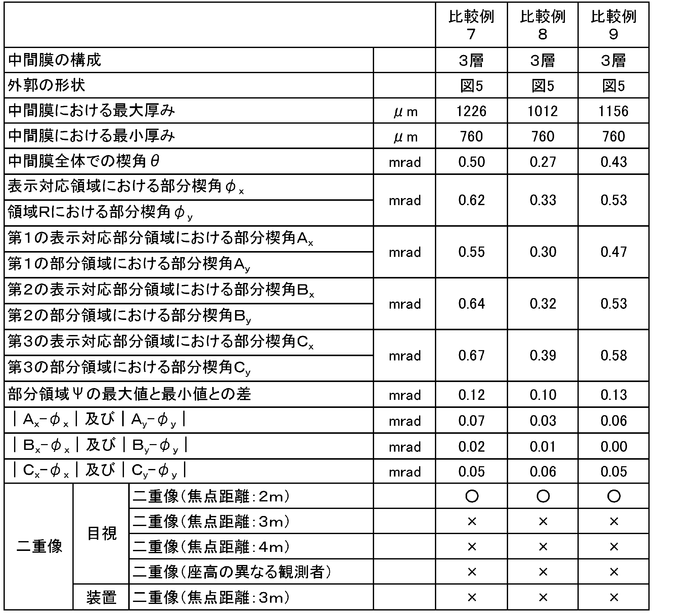
1Aa,1Ca,1Ea…厚み方向の断面形状が矩形である部分
1Ab,1Cb,1Eb…厚み方向の断面形状が楔状である部分
2,2B,2D…第2の層
3,3B,3D…第3の層
11,11A,11B,11C,11D,11E…中間膜
11a…一端
11b…他端
11Aa,11Ca,11Ea…厚み方向の断面形状が矩形である部分
11Ab,11Cb,11Eb…厚み方向の断面形状が楔状である部分
21…合わせガラス
22…第1の合わせガラス部材
23…第2の合わせガラス部材
R1…表示対応領域
R2…周囲領域
R3…シェード領域
R11…第1の表示対応部分領域
R12…第2の表示対応部分領域
R13…第3の表示対応部分領域
51…ロール体
61…巻き芯
Claims (13)
- ヘッドアップディスプレイである合わせガラスに用いられる合わせガラス用中間膜であって、
一端と、前記一端の反対側に他端とを有し、
前記他端の厚みが、前記一端の厚みよりも大きく、
ヘッドアップディスプレイの表示領域に対応する表示対応領域を有し、
前記表示対応領域を前記一端と前記他端とを結ぶ方向にて3個に等分割して得られる3領域を、前記一端側から順番に、第1の表示対応部分領域、第2の表示対応部分領域、第3の表示対応部分領域としたときに、
前記第1の表示対応部分領域における部分楔角Axと、前記表示対応領域における部分楔角φxとの差の絶対値が0.05mrad以下であり、
前記第2の表示対応部分領域における部分楔角Bxと、前記表示対応領域における部分楔角φxとの差の絶対値が0.05mrad以下であり、
前記第3の表示対応部分領域における部分楔角Cxと、前記表示対応領域における部分楔角φxとの差の絶対値が0.05mrad以下である、合わせガラス用中間膜。 - 一端と、前記一端の反対側に他端とを有し、
前記他端の厚みが、前記一端の厚みよりも大きく、
中間膜の前記一端から前記他端に向けて10cmの位置から59.5cmの位置までの領域を領域R、中間膜の前記一端から前記他端に向けて10cmの位置から26.5cmの位置までの領域を第1の部分領域、中間膜の前記一端から前記他端に向けて26.5cmの位置から43cmの位置までの領域を第2の部分領域、中間膜の前記一端から前記他端に向けて43cmの位置から59.5cmの位置までの領域を第3の部分領域としたときに、
前記第1の部分領域における部分楔角Ayと、前記領域Rにおける部分楔角φyとの差の絶対値が0.05mrad以下であり、
前記第2の部分領域における部分楔角Byと、前記領域Rにおける部分楔角φyとの差の絶対値が0.05mrad以下であり、
前記第3の部分領域における部分楔角Cyと、前記領域Rにおける部分楔角φyとの差の絶対値が0.05mrad以下である、合わせガラス用中間膜。 - 中間膜全体での楔角θが、0.05mrad以上である、請求項1又は2に記載の合わせガラス用中間膜。
- 熱可塑性樹脂を含む、請求項1~3のいずれか1項に記載の合わせガラス用中間膜。
- 可塑剤を含む、請求項1~4のいずれか1項に記載の合わせガラス用中間膜。
- 第1の層と、
前記第1の層の第1の表面側に配置された第2の層とを備える、請求項1~5のいずれか1項に記載の合わせガラス用中間膜。 - 前記第1の層が、ポリビニルアセタール樹脂を含み、
前記第2の層が、ポリビニルアセタール樹脂を含み、
前記第1の層中の前記ポリビニルアセタール樹脂の水酸基の含有率が、前記第2の層中の前記ポリビニルアセタール樹脂の水酸基の含有率よりも低い、請求項6に記載の合わせガラス用中間膜。 - 前記第1の層が、ポリビニルアセタール樹脂を含み、
前記第2の層が、ポリビニルアセタール樹脂を含み、
前記第1の層が、可塑剤を含み、
前記第2の層が、可塑剤を含み、
前記第1の層中の前記ポリビニルアセタール樹脂100重量部に対する前記第1の層中の前記可塑剤の含有量が、前記第2の層中の前記ポリビニルアセタール樹脂100重量部に対する前記第2の層中の前記可塑剤の含有量よりも多い、請求項6又は7に記載の合わせガラス用中間膜。 - ヘッドアップディスプレイである合わせガラスであって、
一端と、前記一端の反対側に他端とを有し、
前記他端の厚みが、前記一端の厚みよりも大きく、
ヘッドアップディスプレイの表示領域を有し、
第1の合わせガラス部材と、第2の合わせガラス部材と、前記第1の合わせガラス部材と前記第2の合わせガラス部材との間に配置された中間膜とを備え、
前記中間膜は、前記表示領域に対応する表示対応領域を有し、
前記表示対応領域を前記一端と前記他端とを結ぶ方向にて3個に等分割して得られる3領域を、前記一端側から順番に、第1の表示対応部分領域、第2の表示対応部分領域、第3の表示対応部分領域としたときに、
前記第1の表示対応部分領域における前記中間膜の部分楔角Axと、前記表示対応領域における前記中間膜の部分楔角φxとの差の絶対値が0.05mrad以下であり、
前記第2の表示対応部分領域における前記中間膜の部分楔角Bxと、前記表示対応領域における前記中間膜の部分楔角φxとの差の絶対値が0.05mrad以下であり、
前記第3の表示対応部分領域における前記中間膜の部分楔角Cxと、前記表示対応領域における前記中間膜の部分楔角φxとの差の絶対値が0.05mrad以下である、合わせガラス。 - 一端と、前記一端の反対側に他端とを有し、
前記他端の厚みが、前記一端の厚みよりも大きく、
第1の合わせガラス部材と、第2の合わせガラス部材と、前記第1の合わせガラス部材と前記第2の合わせガラス部材との間に配置された中間膜とを備え、
前記中間膜の前記一端から前記他端に向けて10cmの位置から59.5cmの位置までの領域を領域R、前記中間膜の前記一端から前記他端に向けて10cmの位置から26.5cmの位置までの領域を第1の部分領域、前記中間膜の前記一端から前記他端に向けて26.5cmの位置から43cmの位置までの領域を第2の部分領域、前記中間膜の前記一端から前記他端に向けて43cmの位置から59.5cmの位置までの領域を第3の部分領域としたときに、
前記第1の部分領域における前記中間膜の部分楔角Ayと、前記領域Rにおける前記中間膜の部分楔角φyとの差の絶対値が0.05mrad以下であり、
前記第2の部分領域における前記中間膜の部分楔角Byと、前記領域Rにおける前記中間膜の部分楔角φyとの差の絶対値が0.05mrad以下であり、
前記第3の部分領域における前記中間膜の部分楔角Cyと、前記領域Rにおける前記中間膜の部分楔角φyとの差の絶対値が0.05mrad以下である、合わせガラス。 - 前記中間膜全体での楔角θが、0.05mrad以上である、請求項9又は10に記載の合わせガラス。
- 前記第1の合わせガラス部材の楔角が、0.05mrad以上である、請求項9~11のいずれか1項に記載の合わせガラス。
- 前記第2の合わせガラス部材の楔角が、0.05mrad以上である、請求項9~12のいずれか1項に記載の合わせガラス。
Priority Applications (6)
| Application Number | Priority Date | Filing Date | Title |
|---|---|---|---|
| JP2019556293A JP7477974B2 (ja) | 2018-10-09 | 2019-10-09 | 合わせガラス用中間膜及び合わせガラス |
| CN201980066071.2A CN112805258A (zh) | 2018-10-09 | 2019-10-09 | 夹层玻璃用中间膜以及夹层玻璃 |
| MX2021003957A MX2021003957A (es) | 2018-10-09 | 2019-10-09 | Pelicula intermedia para vidrio laminado y vidrio laminado. |
| EP19870220.1A EP3865465A4 (en) | 2018-10-09 | 2019-10-09 | Intermediate film for laminated glass and laminated glass |
| KR1020217010126A KR102847567B1 (ko) | 2018-10-09 | 2019-10-09 | 접합 유리용 중간막 및 접합 유리 |
| US17/282,566 US11820106B2 (en) | 2018-10-09 | 2019-10-09 | Intermediate film for laminated glass and laminated glass |
Applications Claiming Priority (2)
| Application Number | Priority Date | Filing Date | Title |
|---|---|---|---|
| JP2018191006 | 2018-10-09 | ||
| JP2018-191006 | 2018-10-09 |
Publications (1)
| Publication Number | Publication Date |
|---|---|
| WO2020075747A1 true WO2020075747A1 (ja) | 2020-04-16 |
Family
ID=70164542
Family Applications (1)
| Application Number | Title | Priority Date | Filing Date |
|---|---|---|---|
| PCT/JP2019/039794 Ceased WO2020075747A1 (ja) | 2018-10-09 | 2019-10-09 | 合わせガラス用中間膜及び合わせガラス |
Country Status (8)
| Country | Link |
|---|---|
| US (1) | US11820106B2 (ja) |
| EP (1) | EP3865465A4 (ja) |
| JP (1) | JP7477974B2 (ja) |
| KR (1) | KR102847567B1 (ja) |
| CN (1) | CN112805258A (ja) |
| MX (1) | MX2021003957A (ja) |
| TW (1) | TWI827698B (ja) |
| WO (1) | WO2020075747A1 (ja) |
Cited By (2)
| Publication number | Priority date | Publication date | Assignee | Title |
|---|---|---|---|---|
| JPWO2021256554A1 (ja) * | 2020-06-18 | 2021-12-23 | ||
| EP3988295A1 (en) * | 2020-10-26 | 2022-04-27 | Kuraray Europe GmbH | Process for the production of windshields with reduced optical distortion |
Families Citing this family (1)
| Publication number | Priority date | Publication date | Assignee | Title |
|---|---|---|---|---|
| CN118406332B (zh) * | 2024-05-16 | 2025-02-07 | 浙江德斯泰新材料股份有限公司 | 一种楔形pvb膜及在hud前挡风玻璃的应用 |
Citations (4)
| Publication number | Priority date | Publication date | Assignee | Title |
|---|---|---|---|---|
| JPH04502525A (ja) | 1989-10-16 | 1992-05-07 | リビー―オーウェンズ―フォード・カンパニー | 車輌のウィンドシールド用表示パネル |
| JP2017502124A (ja) * | 2013-12-12 | 2017-01-19 | サン−ゴバン グラス フランスSaint−Gobain Glass France | 垂直方向でセクションごとに非線形に連続する楔形挿入部材を含む、積層ガラスパネル用の熱可塑性フィルム |
| JP2017105665A (ja) * | 2015-12-08 | 2017-06-15 | 旭硝子株式会社 | 合わせガラス |
| WO2018181689A1 (ja) * | 2017-03-30 | 2018-10-04 | 積水化学工業株式会社 | 合わせガラス用中間膜及び合わせガラス |
Family Cites Families (5)
| Publication number | Priority date | Publication date | Assignee | Title |
|---|---|---|---|---|
| CN103080037B (zh) | 2010-09-01 | 2015-07-01 | 积水化学工业株式会社 | 夹层玻璃用中间膜及夹层玻璃 |
| US20160168353A1 (en) * | 2014-12-08 | 2016-06-16 | Solutia Inc. | Interlayers having enhanced optical properties |
| KR102609898B1 (ko) | 2015-09-28 | 2023-12-06 | 세키스이가가쿠 고교가부시키가이샤 | 접합 유리용 중간막 및 접합 유리 |
| KR102609909B1 (ko) | 2015-09-30 | 2023-12-06 | 세키스이가가쿠 고교가부시키가이샤 | 접합 유리용 중간막 및 접합 유리 |
| US9931821B2 (en) * | 2015-10-19 | 2018-04-03 | Solutia Inc. | Multiple layer interlayers having enhanced properties |
-
2019
- 2019-10-09 MX MX2021003957A patent/MX2021003957A/es unknown
- 2019-10-09 CN CN201980066071.2A patent/CN112805258A/zh active Pending
- 2019-10-09 EP EP19870220.1A patent/EP3865465A4/en active Pending
- 2019-10-09 TW TW108136701A patent/TWI827698B/zh active
- 2019-10-09 US US17/282,566 patent/US11820106B2/en active Active
- 2019-10-09 KR KR1020217010126A patent/KR102847567B1/ko active Active
- 2019-10-09 JP JP2019556293A patent/JP7477974B2/ja active Active
- 2019-10-09 WO PCT/JP2019/039794 patent/WO2020075747A1/ja not_active Ceased
Patent Citations (4)
| Publication number | Priority date | Publication date | Assignee | Title |
|---|---|---|---|---|
| JPH04502525A (ja) | 1989-10-16 | 1992-05-07 | リビー―オーウェンズ―フォード・カンパニー | 車輌のウィンドシールド用表示パネル |
| JP2017502124A (ja) * | 2013-12-12 | 2017-01-19 | サン−ゴバン グラス フランスSaint−Gobain Glass France | 垂直方向でセクションごとに非線形に連続する楔形挿入部材を含む、積層ガラスパネル用の熱可塑性フィルム |
| JP2017105665A (ja) * | 2015-12-08 | 2017-06-15 | 旭硝子株式会社 | 合わせガラス |
| WO2018181689A1 (ja) * | 2017-03-30 | 2018-10-04 | 積水化学工業株式会社 | 合わせガラス用中間膜及び合わせガラス |
Non-Patent Citations (1)
| Title |
|---|
| See also references of EP3865465A4 |
Cited By (5)
| Publication number | Priority date | Publication date | Assignee | Title |
|---|---|---|---|---|
| JPWO2021256554A1 (ja) * | 2020-06-18 | 2021-12-23 | ||
| WO2021256554A1 (ja) * | 2020-06-18 | 2021-12-23 | 日本化薬株式会社 | ヘッドアップディスプレイ用光学積層体、機能性ガラス、及びヘッドアップディスプレイシステム |
| JP7737987B2 (ja) | 2020-06-18 | 2025-09-11 | 日本化薬株式会社 | ヘッドアップディスプレイ用光学積層体、機能性ガラス、及びヘッドアップディスプレイシステム |
| EP3988295A1 (en) * | 2020-10-26 | 2022-04-27 | Kuraray Europe GmbH | Process for the production of windshields with reduced optical distortion |
| WO2022089901A1 (en) * | 2020-10-26 | 2022-05-05 | Kuraray Europe Gmbh | Process for the production of windshields with reduced optical distortion |
Also Published As
| Publication number | Publication date |
|---|---|
| JPWO2020075747A1 (ja) | 2021-09-02 |
| EP3865465A1 (en) | 2021-08-18 |
| US20210339505A1 (en) | 2021-11-04 |
| EP3865465A4 (en) | 2022-06-29 |
| TW202027987A (zh) | 2020-08-01 |
| KR20210073523A (ko) | 2021-06-18 |
| US11820106B2 (en) | 2023-11-21 |
| TWI827698B (zh) | 2024-01-01 |
| JP7477974B2 (ja) | 2024-05-02 |
| KR102847567B1 (ko) | 2025-08-20 |
| CN112805258A (zh) | 2021-05-14 |
| MX2021003957A (es) | 2021-05-27 |
Similar Documents
| Publication | Publication Date | Title |
|---|---|---|
| JP6581596B2 (ja) | 合わせガラス用中間膜及び合わせガラス | |
| JP6783855B2 (ja) | 合わせガラス用中間膜、ロール体及び合わせガラス | |
| JP2022003009A (ja) | 合わせガラス用中間膜及び合わせガラス | |
| JP6449524B1 (ja) | 合わせガラス用中間膜及び合わせガラス | |
| JP7084140B2 (ja) | 合わせガラス用中間膜及び合わせガラス | |
| JP2020073423A (ja) | 合わせガラス用中間膜及び合わせガラス | |
| JP7477974B2 (ja) | 合わせガラス用中間膜及び合わせガラス | |
| JP7269390B2 (ja) | 合わせガラス用中間膜及び合わせガラス | |
| JP7372835B2 (ja) | 合わせガラス用中間膜及び合わせガラス | |
| JP7201583B2 (ja) | 合わせガラス | |
| JP7412173B2 (ja) | 合わせガラス | |
| JP7100975B2 (ja) | 合わせガラス | |
| JP6484351B2 (ja) | 合わせガラス用中間膜、ロール体及び合わせガラス | |
| JP7112386B2 (ja) | 合わせガラス用中間膜及び合わせガラス |
Legal Events
| Date | Code | Title | Description |
|---|---|---|---|
| ENP | Entry into the national phase |
Ref document number: 2019556293 Country of ref document: JP Kind code of ref document: A |
|
| 121 | Ep: the epo has been informed by wipo that ep was designated in this application |
Ref document number: 19870220 Country of ref document: EP Kind code of ref document: A1 |
|
| WWE | Wipo information: entry into national phase |
Ref document number: 2101001997 Country of ref document: TH |
|
| NENP | Non-entry into the national phase |
Ref country code: DE |
|
| ENP | Entry into the national phase |
Ref document number: 2019870220 Country of ref document: EP Effective date: 20210510 |
|
| WWR | Wipo information: refused in national office |
Ref document number: 1020217010126 Country of ref document: KR |