WO2020079906A1 - ヘッドマウントディスプレイおよびこれに用いられる広焦点レンズの設計方法 - Google Patents
ヘッドマウントディスプレイおよびこれに用いられる広焦点レンズの設計方法 Download PDFInfo
- Publication number
- WO2020079906A1 WO2020079906A1 PCT/JP2019/028635 JP2019028635W WO2020079906A1 WO 2020079906 A1 WO2020079906 A1 WO 2020079906A1 JP 2019028635 W JP2019028635 W JP 2019028635W WO 2020079906 A1 WO2020079906 A1 WO 2020079906A1
- Authority
- WO
- WIPO (PCT)
- Prior art keywords
- eye
- wide
- virtual image
- lens
- image forming
- Prior art date
- Legal status (The legal status is an assumption and is not a legal conclusion. Google has not performed a legal analysis and makes no representation as to the accuracy of the status listed.)
- Ceased
Links
Images




Classifications
-
- G—PHYSICS
- G02—OPTICS
- G02B—OPTICAL ELEMENTS, SYSTEMS OR APPARATUS
- G02B27/00—Optical systems or apparatus not provided for by any of the groups G02B1/00 - G02B26/00, G02B30/00
- G02B27/01—Head-up displays
- G02B27/017—Head mounted
- G02B27/0172—Head mounted characterised by optical features
-
- G—PHYSICS
- G02—OPTICS
- G02B—OPTICAL ELEMENTS, SYSTEMS OR APPARATUS
- G02B25/00—Eyepieces; Magnifying glasses
- G02B25/001—Eyepieces
-
- G—PHYSICS
- G02—OPTICS
- G02B—OPTICAL ELEMENTS, SYSTEMS OR APPARATUS
- G02B27/00—Optical systems or apparatus not provided for by any of the groups G02B1/00 - G02B26/00, G02B30/00
- G02B27/0012—Optical design, e.g. procedures, algorithms, optimisation routines
-
- G—PHYSICS
- G02—OPTICS
- G02B—OPTICAL ELEMENTS, SYSTEMS OR APPARATUS
- G02B27/00—Optical systems or apparatus not provided for by any of the groups G02B1/00 - G02B26/00, G02B30/00
- G02B27/0075—Optical systems or apparatus not provided for by any of the groups G02B1/00 - G02B26/00, G02B30/00 with means for altering, e.g. increasing, the depth of field or depth of focus
-
- G—PHYSICS
- G02—OPTICS
- G02B—OPTICAL ELEMENTS, SYSTEMS OR APPARATUS
- G02B3/00—Simple or compound lenses
- G02B3/02—Simple or compound lenses with non-spherical faces
-
- G—PHYSICS
- G02—OPTICS
- G02C—SPECTACLES; SUNGLASSES OR GOGGLES INSOFAR AS THEY HAVE THE SAME FEATURES AS SPECTACLES; CONTACT LENSES
- G02C11/00—Non-optical adjuncts; Attachment thereof
- G02C11/10—Electronic devices other than hearing aids
-
- G—PHYSICS
- G02—OPTICS
- G02C—SPECTACLES; SUNGLASSES OR GOGGLES INSOFAR AS THEY HAVE THE SAME FEATURES AS SPECTACLES; CONTACT LENSES
- G02C7/00—Optical parts
- G02C7/02—Lenses; Lens systems ; Methods of designing lenses
- G02C7/022—Ophthalmic lenses having special refractive features achieved by special materials or material structures
-
- G—PHYSICS
- G02—OPTICS
- G02B—OPTICAL ELEMENTS, SYSTEMS OR APPARATUS
- G02B3/00—Simple or compound lenses
- G02B2003/0093—Simple or compound lenses characterised by the shape
-
- G—PHYSICS
- G02—OPTICS
- G02B—OPTICAL ELEMENTS, SYSTEMS OR APPARATUS
- G02B27/00—Optical systems or apparatus not provided for by any of the groups G02B1/00 - G02B26/00, G02B30/00
- G02B27/01—Head-up displays
- G02B27/0101—Head-up displays characterised by optical features
- G02B2027/0132—Head-up displays characterised by optical features comprising binocular systems
-
- G—PHYSICS
- G02—OPTICS
- G02B—OPTICAL ELEMENTS, SYSTEMS OR APPARATUS
- G02B27/00—Optical systems or apparatus not provided for by any of the groups G02B1/00 - G02B26/00, G02B30/00
- G02B27/01—Head-up displays
- G02B27/017—Head mounted
- G02B27/0172—Head mounted characterised by optical features
- G02B2027/0174—Head mounted characterised by optical features holographic
-
- G—PHYSICS
- G02—OPTICS
- G02C—SPECTACLES; SUNGLASSES OR GOGGLES INSOFAR AS THEY HAVE THE SAME FEATURES AS SPECTACLES; CONTACT LENSES
- G02C2202/00—Generic optical aspects applicable to one or more of the subgroups of G02C7/00
- G02C2202/24—Myopia progression prevention
Definitions
- the present invention relates to a head mounted display and a design method of a wide focus lens used for the head mounted display.
- a head-mounted display which is a display device worn on the head, displays a stereoscopic image to a user by displaying parallax images corresponding to the left and right eyes on the display.
- a stereoscopic display method of displaying parallax images corresponding to the left and right eyes in this manner is called twin-eye stereoscopic display.
- the HMD can give a high immersive feeling to the user by displaying a wide-angle stereoscopic image with a particularly large angle of view.
- both eyes rotate to capture the stereoscopic image to correctly perceive the depth of the stereoscopic image due to convergence, while the binocular focus is adjusted by being adjusted to the display that displays the parallax image.
- the depth of a stereoscopic image cannot be perceived correctly. Therefore, due to the interaction between the vergence and the accommodation, the vergence accommodation that induces the focus of the eye to the depth perceived by the vergence cannot work for the stereoscopic image by the two-eye stereoscopic display. Thus, it is said that visual fatigue results from the discrepancy between vergence and accommodation.
- a virtual image may be formed at a distance from a few meters ahead to infinity, a stereoscopic image may be displayed in a nearby manual work space, and the stereoscopic image may be interactively operated.
- the contradiction between regulation is more serious.
- Non-Patent Document 1 a virtual image forming system including a variable focal length mirror and a display is provided for each of the left and right eyes, and a virtual image of the display image is formed at a plurality of different depth positions using the variable focal length mirror.
- An HMD is disclosed that enables focusing of the eye on a stereoscopic image by imaging.
- a DMD Digital Micromirror Device
- a display that operates at high speed is required.
- an image processing device is required to generate at high speed an image divided in the depth direction to be displayed on a high speed display.
- Non-Patent Document 2 discloses an HMD that dynamically changes a virtual image forming relationship using a variable focal length lens and a motor in a virtual image forming system including a display, and detects a rotation angle of left and right eyes. It is described that the depth perceived by the convergence is calculated, and the image forming relationship of the image forming system is changed so as to form a virtual image of the image on the display at the depth position.
- the HMD having such a structure requires a means for detecting the rotation angle of the eye.
- the use of a mechanical mechanism including a variable focal length lens and a motor resulting in cost increase and weight increase, becomes a problem.
- the present invention has a simpler configuration and a head-mounted display capable of viewing a stereoscopic image without suffering visual fatigue due to contradiction of convergence adjustment, and a wide-focus lens used for the same. It is intended to provide a design method of.
- a display device for displaying left-eye and right-eye images on a screen, and a left-eye and a right-eye that are respectively arranged for left-eye and right-eye images on the screen
- Virtual image forming optical system and left eye and right eye having a negative focal length and a width, which are respectively arranged to overlap the left eye and right eye virtual image forming optical systems in the respective optical axis directions.
- a wide-focus lens for use in a head-mounted display.
- FIG. 9A is a diagram showing the shape of a wide-focus lens having a negative focal length and a wide width
- FIG. 9B is a diagram showing the distribution of the focal length (refractive power) with respect to the distance from the center. It is the figure which showed the surface shape of the wide focus lens.
- FIG. 6 is a diagram showing a comparative example of the relationship between the angle of the line of sight and the position in the wide-focus lens through which the line of sight passes in a stereoscopic display device having a small angle of view.
- FIG. 7A is a schematic view of an entire wide-focus lens used in the HMD according to the third embodiment
- FIG. 8B is an enlarged view of the upper half of the lens.
- FIG. 3 is a diagram showing a relationship between a line of sight of a user wearing the HMD according to the same embodiment and a wide-focus lens. It is a figure which showed the result of evaluation about the wide-focus lens of FIG. It is the figure which showed the result of the evaluation following FIG.
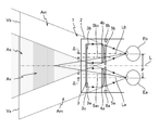
- FIG. 1 shows a schematic configuration of a VR HMD (referred to simply as HMD unless there is confusion) 1 according to the first embodiment.
- the left eye Ea and the right eye Eb of the user are arranged in the vertical direction of the drawing, this direction is the left-right direction, and the left-right direction of the drawing is the front-back direction.
- a reference line extending in the front-rear direction through the centers of the left eye Ea and the right eye Eb is the center line L
- a reference line extending from the left eye Ea and the right eye Eb to the left in the drawing in parallel with the center line L is the main line of sight.
- the separation distance P between the left eye Ea and the right eye Eb of the user is set to be, for example, the average separation distance between the left and right eyes of an adult (typically 65 mm).
- the HMD 1 includes a frame 2, a display device 3, virtual image forming optical systems 4a and 4b for the left and right eyes, wide-focus lenses 5a and 5b for the left and right eyes, and actuators 6a and 6b.
- the frame 2 is a housing that holds the display device 3 and other components of the configuration.
- the shape of the frame 2 is such that the front surface is closed so as to hold the display device 3 inside, the back surface is opened so that the display surface of the display device 3 can be viewed from the back side, and the periphery of both eyes looking into the display device 3 is covered. Any shape may be used as long as the side surface surrounds the front surface.
- a wearing band (not shown) for wearing the HMD 1 in front of the user's face may be provided by connecting the one side of the frame 2 around the occiput of the user to the other side.
- the main lines of sight La and Lb of the left eye Ea and the right eye Eb are overlapped or substantially overlapped with the optical axes of the left and right eye virtual image forming optical systems 4a and 4b, respectively.
- the left-eye and right-eye virtual image forming optical systems 4a and 4b are held in the frame 2.
- the display device 3 is a device that displays left-eye and right-eye images 3a and 3b on the screen 3c.
- a flat panel display such as a liquid crystal display or an organic EL display can be used.
- the display device 3 is held on the back side of the front surface of the frame 2 with the screen 3c facing the back side.
- the screen 3c of the display device 3 includes two regions that are located on the main lines of sight La and Lb of the left eye Ea and the right eye Eb and display the left eye and right eye images 3a and 3b, respectively. Note that, instead of the display device 3 having the single screen 3c, two display devices that respectively display the left-eye and right-eye images 3a and 3b may be used.
- the left-eye and right-eye virtual image forming optical systems (also simply referred to as virtual image forming optical systems) 4a and 4b are used for the left-eye and right-eye images 3a and 3b on the screen 3c of the display device 3. These are optical systems that are respectively arranged and form virtual images of the left-eye and right-eye images 3a and 3b on the virtual image display surfaces Va and Vb, respectively, and project the magnified erect images to the left eye Ea and the right eye Eb.
- the left-eye and right-eye virtual image forming optical systems 4a and 4b are each shown to be configured by a single virtual image forming lens, but are configured by combining a plurality of optical elements. May be.
- the left-eye and right-eye virtual image forming optical systems 4a and 4b are arranged behind two regions on the screen 3c on which the left-eye and right-eye images 3a and 3b are displayed, respectively. .
- the left eye Ea and the right eye Eb pass through the left-eye and right-eye virtual image forming optical systems 4a and 4b, respectively, but virtually without the left-eye and right-eye wide-focus lenses 5a and 5b,
- the left-eye and right-eye images 3a and 3b on the screen 3c are viewed, their virtual images are displayed on the virtual image display surfaces Va and Vb, respectively.
- the virtual image on the virtual image display surface Va in the overlapping region of the virtual image display surfaces Va and Vb is viewed by the left eye Ea and at the same time.
- the virtual image can be stereoscopically viewed within the region As that faces the overlapping region from both eyes. That is, a stereoscopic image is displayed in the area As. Since the virtual image cannot be viewed binocularly in the areas on the virtual image display surfaces Va and Vb other than the overlapping area, the virtual image on the virtual image display surface Va is simply two-dimensionally viewed by the left eye Ea, and the virtual image on the virtual image display surface Vb is viewed. The virtual image is two-dimensionally viewed by the right eye Eb. That is, the stereoscopic image is not displayed in the area Am.
- the left-eye and right-eye wide-focus lenses 5a and 5b are wide-focus lenses having a negative focal length and a wide width.
- the left-eye and right-eye wide-focus lenses 5a and 5b are arranged to overlap the left-eye and right-eye virtual image forming optical systems 4a and 4b, respectively, in their optical axis directions.
- the virtual images of the left-eye and right-eye images 3a and 3b formed by the left-eye and right-eye virtual image forming optical systems 4a and 4b become the left-eye and right-eye wide-focus lenses 5a, Since the focal length of 5b has a width, an image is formed within a range having a width that spreads in the optical axis direction at a distance and / or in the vicinity of the virtual image display surfaces Va and Vb.
- the left-eye and right-eye wide-focus lenses 5a and 5b are arranged in the vicinity of the left-eye and right-eye virtual image forming optical systems 4a and 4b, and the distance between them is ,
- the distance between the virtual image forming optical systems 4a, 4b for the left and right eyes and the virtual image display surfaces Va, Vb, or the virtual image forming optical systems 4a, 4b for the left and right eyes and the left and right eyes Ea, Eb It should be sufficiently smaller than the distance.
- the left-eye and right-eye wide-focus lenses 5a and 5b are arranged behind the left-eye and right-eye virtual image forming optical systems 4a and 4b, but they are arranged in the front. May be done. Further, the left-eye and right-eye wide-focus lenses 5a and 5b may be brought into contact with the left-eye and right-eye virtual image forming optical systems 4a and 4b, respectively, and may be configured as an integrated body.
- the virtual image forming optical systems 4a and 4b for the right eye are composed of a plurality of optical elements, they may be incorporated between them to form an integrated system.
- the focal lengths of the left-eye and right-eye wide-focus lenses 5a and 5b are determined so that a stereoscopic image can be viewed without suffering visual fatigue caused by the contradiction of convergence adjustment.
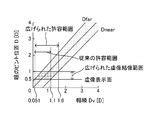
- FIG. 2 shows the relationship between the convergence and the adjustment for comfortable stereoscopic viewing.
- Convergence and accommodation are preferable for comfortable stereoscopic vision in humans, but it is known from studies of visual fatigue that there is some tolerance even if they do not coincide (T. Shibata, J. Kim, DM Hoffman, MS Banks, "The zone of comfort: Predicting visual discomfort with stereo displays," J. Vision, vol. 11, no. 8, p.1-29 (2011)).
- the amount of discrepancy between convergence and accommodation can be expressed using the distal end D far and the proximal end D near of the eye focus position with respect to the depth Dv perceived by the convergence.
- D far and D near use Dv
- D far 1.129 Dv + 0.442
- D near 1.035Dv-0.626 (1b)
- D far , D near , and Dv are given in units of a diopter (Diopter [D]) representing the reciprocal of the distance in meters.
- inconsistency between congestion and regulation is allowed.
- the focus of the eye is set to 0.5D (equal to 2 m)
- the range of depth Dv perceived by the corresponding vergence is 0.051 to 1.1D. (0.92 to 19 m). That is, when the virtual image display surfaces Va and Vb are located at a distance of 2 m from the left eye Ea and the right eye Eb, if a stereoscopic image is displayed within a range of 0.92 to 19 m, visual fatigue due to the contradiction of convergence adjustment may be felt. You can comfortably see stereoscopic images.
- the range in which the stereoscopic image can be comfortably viewed is sufficiently wide in the distance from the virtual image display surfaces Va and Vb, but is not sufficiently wide in the near area.
- a virtual image is formed at a distance of infinity from a point several meters (typically 2 m) ahead of the left eye Ea and the right eye Eb and a stereoscopic image is spread in front of the user ( Since the stereoscopic image is typically displayed interactively by displaying it in the area of about 60 cm from the left eye Ea and the right eye Eb), in the stereoscopic display of the HMD1, the comfortable stereoscopic viewing range is widened to the near side. Is desirable.
- Wide-focus lenses 5a and 5b for the left and right eyes having negative focal lengths are used in order to widen a comfortable stereoscopic view closer to the virtual image display surfaces Va and Vb.
- the focal length ranges of the left-eye and right-eye wide-focus lenses 5a and 5b are f 1 to f 2 , and the left-eye and right-eye wide-focus lenses 5a and 5b to the virtual image display surfaces Va and Vb.
- the distance is l 0 .
- the allowable convergence range obtained by D far and D near is 0.64 to, depending on the near spread of the virtual image forming range (that is, l 1 ( ⁇ l 0 )). It spreads as close as 19 m (0.051 to 1.6 D), which makes it possible to comfortably stereoscopically view in a work space extending in front of the user.
- the following is an example of the design of left-eye and right-eye wide-focus lenses 5a and 5b having a negative focal length and a wide range.
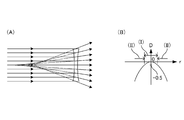
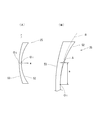
- FIG. 3 shows the shapes (A) of the left-eye and right-eye wide-focus lenses 5a and 5b and the distribution (B) of the focal length with respect to the distance from the center.
- the focal length is represented by the reciprocal of the refractive power.
- the wide-focus lens has a refractive power with a negative value and a minimum absolute value (zero in this embodiment) at the optical center, and has a negative value and a larger absolute value with increasing distance from the optical center. .
- axicon G. Mikula, Z. Jaroszewicz, A. Kolodziejczyk, K. Petelczyc, and M. Sypek, "Images with extended focal depth by means “Opt. Express, vol. 15, no. 15, p.9184-9193 (2007)), Axilens (axilens) (J. Sochacki, A. Kolodziejczyk, Z. Jaroszewicz, and S. Bara," Nonparaxial design of generalized axicons, "Appl. Opt., vol.31, p.5326-5330 (1992)), light sword optical element (N. Davidson, A. A. Friesem, and E.
- the refractive power (the reciprocal of the focal length f ⁇ 1 ) is Using the rate n, Is given.
- Z (r) Er 3 is given by using the coefficient E to obtain a distribution of refractive power, Is obtained.
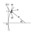
- FIG. 4 shows the surface shape of the wide-focus lens.
- Is minute change dr of the distance r corresponding to the minute length ds along the lens surface and the minute length dZ in the thickness direction.
- the focal length f of the spherical surface having the radius of curvature R is Is given.
- Expression (3) is derived by applying these relational expressions to Expression (6).
- the optical centers of the left-eye and right-eye wide-focus lenses 5a and 5b are left and right with respect to the optical centers (that is, optical axes) of the left-eye and right-eye virtual image forming optical systems 4a and 4b, respectively.
- the lenses are arranged so as to shift toward the center side of both lenses in the direction, that is, closer to the center line L.
- the shift amounts ⁇ of the optical centers of the left-eye and right-eye wide-focus lenses 5a and 5b with respect to the optical axes of the left-eye and right-eye virtual image forming optical systems 4a and 4b are determined.
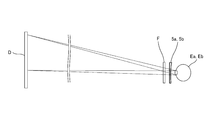
- FIG. 5A shows, as a comparative example, the relationship between the angle of the line of sight and the position in the wide-focus lenses 5a and 5b through which the line of sight passes in a stereoscopic display device with a small angle of view such as a stereoscopic movie or a stereoscopic television.
- the user wears stereoscopic glasses to which the wide-focus lenses 5a and 5b and the filter F are attached, and looks at the display surface D of the display to see a stereoscopic image.
- the filter F is an optical element such as a polarization filter, a liquid crystal shutter, a color filter, or a spectral filter for separating left-eye and right-eye images.
- the light emitted from the display surface D of the display enters the left eye Ea and the right eye Eb via the wide-focus lenses 5a and 5b.
- the display surface The angle of view of D is small, and the light ray group that is emitted from each point on the display surface D and is incident on the left eye Ea and the right eye Eb is a wide-focus lens regardless of the position on the display surface D where the light ray group is emitted.
- 5a and 5b pass through substantially the same position, particularly the optical center. Therefore, the range of the focal lengths of the wide-focus lenses 5a and 5b can be regarded as constant with respect to the viewing direction (that is, the line-of-sight angle) of viewing the display surface D of the display from both eyes Ea and Eb.
- FIG. 5B shows the relationship between the line-of-sight angle and the positions in the wide-focus lenses 5a and 5b through which the line of sight passes in the HMD 1 having a large angle of view.
- a wide angle of view is preferred in order to enhance the immersive feeling, and thus the angles of view of the virtual image display surfaces Va and Vb become large.
- the wide-focus lenses 5a and 5b should be attached to the left eye. It is also necessary to have some separation from Ea and the right eye Eb.
- the light ray group that is emitted from each point of the screen 3c (virtually virtual image display surfaces Va, Vb) of the display device 3 and is incident on the left eye Ea and the right eye Eb has a wide focus depending on the position of each point.
- the lenses 5a and 5b pass through different positions, particularly a range that spreads larger than the pupil. Therefore, the focal lengths and widths of the wide-focus lenses 5a and 5b are different with respect to the viewing direction (that is, the line-of-sight angle) of viewing the virtual image display surfaces Va and Vb from the left eye Ea and the right eye Eb.
- the effect of 5b on virtual image formation that is, how the allowable range of convergence and accommodation spreads changes depending on the viewing direction.
- the areas (II) outside the left-eye and right-eye wide-focus lenses 5a and 5b correspond to the stereoscopic viewing area As, and the allowable range of convergence and adjustment becomes effective. I can't spread it.
- the area (I) near the centers of the left-eye and right-eye wide-focus lenses 5a and 5b is located on the center line L side so as to face the area As. shift.
- the area Am since the virtual image of the two-dimensional display is viewed by only one of the left eye Ea and the right eye Eb, the contradiction of convergence adjustment does not occur.
- the optical centers 5a 0 and 5b 0 of the left-eye and right-eye wide-focus lenses 5a and 5b with respect to the optical axes of the left-eye and right-eye virtual image forming optical systems 4a and 4b (that is, , Optical axis) shift amount ⁇ is a distance P in the left-right direction between the left-eye and right-eye virtual image forming optical systems 4a and 4b, the left-eye and right-eye wide-focus lenses 5a and 5b, and the user's left-eye.
- the range Av in which the left-eye and right-eye wide-focus lenses 5a and 5b display virtual images that is, from the left-eye and right-eye wide-focus lenses 5a and 5b
- the shift amount ⁇ may be determined as Pd / 2Q with respect to the distance Q between the pupils of the user's left eye Ea and right eye Eb and the user's hand, or Pd / 2Q to Pd / 2 ( It may be determined to be within the range of l 0 + d). This enables comfortable stereoscopic viewing within a large work area in front of the user.
- the shift amount ⁇ may be zero when the stereoscopic image is displayed in a narrow range, or when the observation distance is long and the angle of view for that range is small.
- the actuators 6a and 6b are examples of displacement mechanisms, and drive the left-eye and right-eye wide-focus lenses 5a and 5b in the left-right direction with respect to the left-eye and right-eye virtual image forming optical systems 4a and 4b, respectively.
- Drive device An electric motor, for example, can be used as the actuators 6a and 6b.
- the actuators 6a and 6b are respectively held inside the left and right side surfaces of the frame 2 and actuated by operation buttons provided on the side surfaces of the frame 2 to operate the left-eye and right-eye wide-focus lenses 5a and 5b.
- the drive range may include any of the ranges described above. Accordingly, the display range of the stereoscopic image that can be viewed without suffering visual fatigue due to the contradiction of convergence adjustment can be displaced in the direction parallel to the center line L.
- a device for displacing the left-eye and right-eye wide-focus lenses 5a, 5b in the left-right direction by manually operating a dial, a ring, etc. instead of a drive device having a power source such as the actuators 6a, 6b. May be adopted.
- the left-eye and right-eye wide-focus lenses 5a and 5b may be displaced in the left-right direction and tilted. If the shift amount ⁇ does not have a range or the range is sufficiently narrow, the displacement mechanism is not provided and the left-eye and right-eye virtual image forming optical systems 4 a and 4 b may be fixed in the frame 2. .
- the display device 3 that displays the left-eye and right-eye images 3a and 3b on the screen 3c, and the left-eye and right-eye images on the screen 3c.
- the left-eye and right-eye wide-focus lenses 5a and 5b each having a negative focal length and a width are provided so as to be overlapped with each other in the direction.
- Virtual images of the left-eye and right-eye images 3a and 3b formed by the left-eye and right-eye virtual image-forming optical systems 4a and 4b are respectively left-eye and right-eye virtual image-forming optical systems 4a. , 4b with respect to the optical axis directions of the left-eye and right-eye wide-focus lenses 5a and 5b, the focal lengths of the respective wide-focus lenses 5a and 5b are displayed in a range having a width that widens in the vicinity, that is, As the display range of the virtual image expands to the near side, the allowable range of convergence and adjustment expands to the near side, so that it is displayed by the left-eye and right-eye images 3a and 3b in the near wide area. It is possible to view a stereoscopic image without suffering visual fatigue caused by the contradiction of convergence adjustment.
- the left-eye and right-eye wide-focus lenses 5a and 5b having a negative focal length and a wide width are provided in the existing HMD for the left-eye and the right-eye.
- the virtual image forming optical systems 4a and 4b so as to overlap each other in the optical axis direction, the display range of the virtual image is expanded closer to the virtual image display surfaces Va and Vb, thereby allowing convergence and adjustment.
- the stereoscopic image represented by the left-eye and right-eye images 3a and 3b can be viewed within the wide area in the vicinity without suffering visual fatigue due to the contradiction of convergence adjustment. It becomes possible.
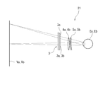
- FIG. 7 shows a schematic configuration of an AR HMD (simply referred to as an HMD unless there is confusion) 11 according to the second embodiment.
- the HMD 11 includes a frame 12, left eye and right eye display devices 13a and 13b, left eye and right eye half mirrors 17a and 17b, left eye and right eye virtual image forming optical systems 4a and 4b, and left eye. And right-eye wide-focus lenses 5a and 5b, and actuators 6a and 6b.
- the same components as those of the HMD 1 according to the first embodiment are designated by the same reference numerals and the description thereof will be omitted.
- the frame 12 is a housing that holds the left-eye and right-eye display devices 13a and 13b and other components.
- the frame 12 holds the left-eye and right-eye display devices 13a and 13b inside the left and right side surfaces, respectively, and has a back surface opened so that the inside can be viewed from the back side.
- Has a translucent front surface so as to face the front, and on the main line of sight La, Lb of the left eye Ea and the right eye Eb so that the display surfaces of the left and right eye display devices 13a, 13b can be seen.
- the left-eye and right-eye half mirrors 17a and 17b are held, respectively.
- the main line of sight La, Lb of the left eye Ea and the right eye Eb, which are bent through the left-eye and right-eye half mirrors 17a, 17b, respectively, is for the left eye and the right eye, respectively.
- the left-eye and right-eye virtual image forming optical systems 4a and 4b are held in the frame 12 so as to overlap or substantially overlap the optical axes 4a 0 and 4b 0 of the virtual image forming optical systems 4a and 4b. .
- the left-eye and right-eye display devices 13a and 13b are devices that respectively display left-eye and right-eye images 3a and 3b on their respective screens (also referred to as left-eye and right-eye screens).
- the display devices 13a and 13b for example, flat panel displays such as liquid crystal displays and organic EL displays can be used.
- the left-eye display device 13a is held inside the left side surface of the frame 12 with the screen facing right.
- the right-eye display device 13b is held inside the right side surface of the frame 12 with the screen facing left.
- the left-eye and right-eye half mirrors 17a and 17b reflect the left-eye and right-eye images 3a and 3b displayed on the screens of the left-eye and right-eye display devices 13a and 13b, respectively. It is an optical member for realizing a see-through function in which the light from the target object in front is transmitted to be overlapped with each other to be projected on the left eye Ea and the right eye Eb.
- the left-eye half mirror 17a is on the opposite side to the left-eye screen (left-eye display device 13a) of the left-eye virtual image forming optical system 4a and in front of the user's left-eye Ea (that is, on the main line of sight La). Will be placed.
- the right-eye half mirror 17b is on the opposite side of the right-eye virtual image forming optical system 4b from the right-eye screen (right-eye display device 13b) and in front of the user's right eye Eb (that is, on the main line of sight Lb). Will be placed.
- the left-eye and right-eye virtual image forming optical systems 4a and 4b are arranged on the left and right sides in the frame 12 toward the screens of the left-eye and right-eye display devices 13a and 13b, respectively, and are for the left-eye.
- images 3a and 3b for the right eye are formed as virtual images on the front virtual image display surfaces Va and Vb, respectively, and their enlarged erect images are projected to the left eye Ea and the right eye Eb.
- the virtual image on the virtual image display surface Va in the overlapping region of the virtual image display surfaces Va and Vb is viewed by the left eye Ea and at the same time.
- the virtual image on Vb with the right eye Eb it is possible to stereoscopically view the virtual image in the region As that faces the overlapping region from both eyes, overlapping the target actually existing in the region. That is, the stereoscopic image is projected on the target object in the area As.
- the left-eye and right-eye wide-focus lenses 5a and 5b are wide-focus lenses having a negative focal length and a wide width, and they are provided to the left-eye and right-eye virtual image forming optical systems 4a and 4b, respectively. Are arranged so as to overlap each other in the optical axis direction. As a result, the virtual images of the left-eye and right-eye images 3a and 3b formed by the left-eye and right-eye virtual image forming optical systems 4a and 4b become the left-eye and right-eye wide-focus lenses 5a, Since the focal length of 5b has a width, it is displayed within a range having a width that spreads in the front-rear direction far and / or near the virtual image display surfaces Va and Vb.
- the focal lengths of the left-eye and right-eye wide-focus lenses 5a and 5b are the same as those of the HMD 1 according to the first embodiment so that a stereoscopic image can be viewed without suffering visual fatigue caused by the contradiction of convergence adjustment. It can be defined similarly.
- the image forming range of the virtual image expands closer to the virtual image display surfaces Va and Vb, and the range in which the mismatch between the convergence and the adjustment is allowed expands closer to the user. It becomes possible to see.
- the optical centers 5a 0 and 5b 0 of the left-eye and right-eye wide-focus lenses 5a and 5b are the optical centers of the left-eye and right-eye virtual image forming optical systems 4a and 4b, respectively (that is, The optical axes 4a 0 , 4b 0 ) are arranged rearward, that is, shifted toward the center line L via the left-eye and right-eye half mirrors 17a, 17b.
- the shift amount ⁇ of 0 can be determined similarly to the HMD 1 according to the first embodiment. As a result, it becomes possible to widen the range where comfortable stereoscopic viewing is possible in the stereoscopic viewing area As.
- the actuators 6a and 6b are examples of displacement mechanisms, and the left-eye and right-eye wide-focus lenses 5a and 5b are arranged in the front-rear direction (that is, the left-eye and right-eye virtual image forming optical systems 4a and 4b). , A left-right and a right-eye half mirror 17a, 17b via the left and right direction) driving device.
- the actuators 6a and 6b are respectively held on the left and right of the front surface of the frame 12, and actuated by operation buttons provided on the side surface of the frame 12 to move the left-eye and right-eye wide-focus lenses 5a and 5b in the front-back direction. Drive to. Accordingly, the display range of the stereoscopic image that can be viewed without suffering visual fatigue due to the contradiction of convergence adjustment can be displaced in the direction parallel to the center line L.
- the left-eye and right-eye wide-focus lenses 5a and 5b may be displaced in the front-rear direction and tilted.
- the left-eye display device 13a, the left-eye virtual image forming optical system 4a, and the left-eye wide-focus lens 5a in the frame 12 are left-eye half on the main line of sight La. Although it is arranged on the left side of the mirror 17a, it may be arranged above or below the left-eye half mirror 17a instead.
- the right-eye display device 13b, the right-eye virtual image forming optical system 4b, and the right-eye wide-focus lens 5b in the frame 12 are arranged on the main line of sight Lb for the right-eye half. Although it is arranged on the right side of the mirror 17b, it may be arranged above or below the right-eye half mirror 17b instead.
- the left-eye and right-eye display devices 13a and 13b which display the left-eye and right-eye images 3a and 3b on the screen, respectively.
- the left-eye and right-eye virtual image forming optical systems 4a and 4b and the left-eye and right-eye virtual image forming optical systems 4a and 4b which are arranged for the eye and right-eye images 3a and 3b, respectively.
- the half mirror 17a for the left eye which is arranged on the opposite side to the front of the left eye Ea of the user, and the half mirror 17a for the left eye, which is arranged on the opposite side of the screen for the right eye of the virtual image forming optical system 4b for the right eye and in front of the right eye Eb of the user.
- the right-eye half mirror 17b is provided.
- Virtual images of the left-eye and right-eye images 3a and 3b formed by the left-eye and right-eye virtual image forming optical systems 4a and 4b are left-eye and right-eye wide-focus lenses 5a and 5b, respectively.
- each focal length has a width
- it is displayed within a range having a width that expands in the near direction, that is, the display range of the virtual image expands in the near direction, and the allowable range for congestion and adjustment is near Therefore, it is possible to view the stereoscopic images represented by the left-eye and right-eye images 3a and 3b in a wide area in the vicinity without suffering visual fatigue due to the contradiction of convergence adjustment.
- the wide-eye lenses 5a and 5b for the left eye and the right eye having a negative focal length and a wide width are provided in the existing HMD for the left eye and the right eye.
- the virtual image forming optical systems 4a and 4b so as to overlap each other in the optical axis direction, the display range of the virtual image is expanded closer to the virtual image display surfaces Va and Vb, thereby allowing convergence and adjustment.
- the stereoscopic image represented by the left-eye and right-eye images 3a and 3b can be viewed within the wide area in the vicinity without suffering visual fatigue due to the contradiction of convergence adjustment. It becomes possible.
- the left-eye and right-eye virtual image forming optical systems 4a and 4b and the left-eye and right-eye wide-focus lenses 5a that are independently configured, respectively. , 5b, but instead, an imaging system having at least one free-form lens designed to have both functions of a virtual image forming optical system and a wide-focus lens is provided for the left eye and the right eye. You may be prepared for this.
- the left-eye and right-eye half mirrors 17a and 17b are used to have the see-through function, but instead of this, the planar waveguide is used for downsizing the device. Also, holographic optical elements may be used in combination.
- the left-eye and right-eye images 3a and 3b displayed by the display device 3 and the left-eye and right-eye display devices 13a and 13b may be in color. Monochrome is also acceptable. In the case of color, an optical system for correcting chromatic aberration may be further provided.
- the basic configuration of the HMD 21 is the same as the HMD 1 according to the first embodiment, and the HMD 21 uses the wide-focus lens 25 shown below as the left-eye and right-eye wide-focus lenses 5a and 5b. Is different.
- the wide-focus lens 25 is a lens in which the refractive power (power) at the optical center is 0 diopter and the average power gradually changes from the optical center toward the lens peripheral portion toward the negative side. Since the focal length is represented by the reciprocal of the refractive power, the wide-focus lens 25 has a negative focal length and a wide width.
- the front, back, left and right, and the top and bottom of the user wearing the HMD 21 using the wide-focus lens 25 are referred to as the front, rear, left and right, and the top and bottom of the lens, respectively.
- FIG. 8A shows an overall schematic view of the wide-focus lens 25.
- the rear surface 52 is a concave surface defined by the following expression (7)
- the front surface 53 is a convex surface defined by the following expression (8).
- the axis in the front-back direction that passes through the optical center O of the wide-focus lens 25 (the base point O 1 on the rear surface 52 and the base point O 2 on the front surface 53) is the z-axis
- the direction toward the rear of the wide-focus lens 25 is the z-axis.
- the z axis coincides with the optical axis of the wide focus lens 25.
- R in the equations (7) and (8) is the distance from the z axis. That is, when considering an orthogonal coordinate system with the base point O 1 on the rear surface 52 and the base point O 2 on the front surface 53 as centers, the horizontal and vertical axes orthogonal to the z-axis are the x-axis and the y-axis, respectively. (X 2 + y 2 ) 1/2 . R 1 and R 2 are radii of curvature at the vertices of the surface, and K (conic coefficient) is 1.
- ⁇ 1 is represented by Ar 4 + Br 6 + Cr 8 + Dr 10 (where r is the distance from the z axis and A, B, C, and D are constants). It is the first aspherical component.
- ⁇ 2 is a second aspherical component represented by Er 3 (where r is the distance from the z axis and E is a positive constant). Therefore, in the wide-focus lens 25 of this example, the front surface 53 is spherical and the rear surface 52 is aspherical. Note that R 1 and R 2 are determined by the prescription frequency (0D in this example).
- the wide-focus lens 25 of this example has a refracting surface of the lens rear surface 52 determined based on the prescription power (a spherical surface having a radius of curvature R 1 in this example.
- a spherical surface having a radius of curvature R 1 in this example also referred to as an original spherical surface, which is indicated by a symbol S). .
- aspherical components ⁇ 1 and ⁇ 2 are added.
- the second aspherical component ⁇ 2 represented by Er 3 is substantially linear from the optical center toward the lens peripheral edge along the radial direction of the lens with the average power ⁇ toward the minus side. Has the effect of changing to. Therefore, according to the wide-focus lens 25, the focusable range is widened and the focal length can be widened.
- the value of the constant E can be appropriately set so as to obtain a target allowable range of congestion and adjustment.
- the constant E is 1.66 ⁇ 10 ⁇ 5
- the average dioptric power change in stereoscopic vision is about 0.5 D when the pupil diameter is 5 mm, and the congestion and adjustment are adjusted to the extent illustrated in paragraphs 0023 to 0025. It is possible to widen the allowable range with.
- ⁇ is the height in the z-axis direction at the radius a with the original spherical surface S as a reference (that is, the increase in thickness from the original spherical surface S)
- E 7.68 ⁇ 10 ⁇ 6
- a is 25 mm and ⁇ indicating the increase in thickness is 120 ⁇ m.
- E ⁇ / 1000 / a 3 holds (however, the unit of a: mm, the unit of ⁇ : ⁇ m).
- the refractive surface of the front surface 53 and the refractive surface of the rear surface 52 of the wide-focus lens 25 are determined based on the prescription power. This determination method is well known and will not be described in detail here.
- an aspherical component is added to the refracting surface (original spherical surface S) of the rear surface 52 of the lens determined based on the prescription power.
- An aspherical component is added to the refracting surface of the rear surface 52 by the second aspherical component adding step of adding the second aspherical component ⁇ 2 .
- the first aspherical surface component adding step the first aspherical surface component ⁇ represented by Ar 4 + Br 6 + Cr 8 + Dr 10 (where r is the distance from the z axis and A, B, C and D are constants). 1 is obtained and added to the refracting surface of the rear surface 52.
- the average dioptric power can be made substantially constant along the radial direction of the lens, as indicated by the broken line ⁇ in FIG.
- the first aspherical component ⁇ 1 is obtained by performing a ray tracing simulation on the refracting surface shape of the rear surface 52 expressed by the following aspherical expression (9), and calculating the power (specifically, the refractive power in the meridional direction and the sagittal direction).
- the optimum aspherical surface coefficients A, B, C, D for suppressing the change of the average power with the refractive power in the direction) are obtained, and the first aspherical surface component ⁇ 1 is calculated from the values of these aspherical surface coefficients. Obtainable.
- z r 2 / (R 1 + (R 1 2 -Kr 2 ) 1/2 ) + Ar 4 + Br 6 + Cr 8 + Dr 10 (9)
- z is the sag value on the rear surface 52
- r is the distance from the z axis
- R 1 is the radius of curvature of the vertex
- A, B, C and D are constants (aspherical coefficients).
- a second aspherical surface component ⁇ 2 represented by Er 3 (where r is a distance from the z axis and E is a constant) is added to the refracting surface of the rear surface 52.
- E is a constant
- the absolute value of the constant E is increased, the range in which stereoscopic viewing can be comfortably performed (allowable range between convergence and adjustment) can be expanded.
- the absolute value of the constant E is excessively increased, the resolution of the obtained image will decrease. Therefore, it is preferable to set the constant E so that the absolute value of the constant E falls within the range of 6.40 ⁇ 10 ⁇ 7 to 6.40 ⁇ 10 ⁇ 5 .
- FIG. 11 and 12 show the evaluation results of the wide-focus lens of Example 3.
- FIG. 11 is a result (number of answers: 4) obtained 30 minutes after the start of viewing the movie.
- FIG. 12 is a result (number of answers: 3) obtained 120 minutes after the start of viewing.
- the results of “somewhat good” were more than half of the results of the wide-focus lens of Example 2 in terms of “ease of viewing” and “eye strain”. Especially when the viewing time was long, the ratio of "somewhat good” was high. Further, the wide-focus lenses of the other Examples 1, 2 and 4 have almost the same results. By using a wide-focus lens that has the effect of widening the virtual image display range to the near side due to the wide focal length, it is thought that this is due to the effect of expanding the display range of the stereoscopic image that can be comfortably stereoscopically viewed to the near side. To be
- the HMD 21 is for the left eye and the right eye, which are respectively overlapped with the left-eye and right-eye virtual image forming optical systems 4a and 4b in the respective optical axis directions.
- the wide-focus lenses 5a and 5b are obtained by adding a second aspherical component represented by Er 3 together with a first aspherical component represented by Ar 4 + Br 6 + Cr 8 + Dr 10 .
- the power of the wide-focus lenses 5a and 5b changes in the radial direction due to the second aspherical component represented by Er 3 . That is, the focal lengths of the wide-focus lenses 5a and 5b have a width and the range in which a virtual image is formed spreads in the optical axis direction, and accordingly, comfort is achieved without suffering visual fatigue due to contradiction of convergence adjustment. It is possible to widen the allowable range of convergence and adjustment that can see a stereoscopic image.
- FIG. 10 is a diagram showing a relationship between the user's line of sight and the wide-focus lenses 5a and 5b in the HMD 21 having a large angle of view.
- a wide angle of view is preferred to enhance the immersive feeling, and the angles of view of the virtual image display surfaces Va and Vb become large. Therefore, the group of light rays emitted from the screen 3c of the display device 3 and incident on the left eye Ea and the right eye Eb are close to the peripheral portions as well as the central portions of the wide-focus lenses 5a and 5b, as shown in FIG. It may pass through the area.
- the light ray group incident on the left eye Ea or the right eye Eb is a lens of the wide-focus lenses 5a and 5b. Even when passing through the region close to the peripheral portion, it is possible to ensure the effect of the wide-focus lenses 5a and 5b on virtual image formation, that is, the effect of widening the allowable range of convergence and adjustment.
- the HMD 21 of the above embodiment is a VR HMD, it is also possible to use the wide-focus lens 25 for an AR HMD.
- the above embodiment is an example in which the first aspherical component ⁇ 1 is added to the rear surface 52 of the wide-focus lens, but the first aspherical component ⁇ 1 is added to the front surface 53 of the wide-focus lens. Alternatively, it may be added to both the front surface 53 and the rear surface 52.
- the first aspherical component ⁇ 1 represented by Ar 4 + Br 6 (in this case, the values of constants C and D are zero) is added to the front surface 53, and further the rear surface 52 is represented by Cr 8 + Dr 10. It is also possible to add the first aspherical component ⁇ 1 (in this case, the values of the constants A and B are zero). Whatever surface is added, it is sufficient that fluctuation of the average power from the optical center to the lens peripheral portion can be suppressed.
- the above embodiment is an example in which the second aspherical component ⁇ 2 is added to the rear surface 52 of the wide-focus lens, but the second aspherical component ⁇ 2 is added to the front surface 53 of the wide-focus lens. It is also possible.
- a wide-focus lens in which a power component for correcting at least any of myopia, hyperopia, and astigmatism is further set. It is also possible to use.
- HMD Head mounted display
- 2 ... Frame
- 3 ... Display device 3a ... Left eye image, 3b ... Right eye image, 3c ... Screen
- 4a Left eye virtual image formation optics (virtual image forming optical system), 4b ... right-eye virtual image forming optical system (a virtual image forming optical system), 4a 0, 4b 0 ... optical axis, 5a ... left eye wide lens (wide lens) 5b ... wide-focus lens for right eye (wide-focus lens), 5a 0 , 5b 0 ...
- Optical center 6a, 6b ... Actuator, 11 ... Head mounted display (HMD, HMD for AR), 12 ... Frame, 13a ...
Landscapes
- Physics & Mathematics (AREA)
- General Physics & Mathematics (AREA)
- Optics & Photonics (AREA)
- Health & Medical Sciences (AREA)
- Ophthalmology & Optometry (AREA)
- General Health & Medical Sciences (AREA)
- Acoustics & Sound (AREA)
- Otolaryngology (AREA)
- Lenses (AREA)
Abstract
輻輳調節矛盾に起因する視覚疲労を被ることなく立体像を視ることが可能なヘッドマウントディスプレイを提供する。ヘッドマウントディスプレイ1は、左眼用及び右眼用画像3a,3bを画面3c上に表示する表示装置3、画面上の左眼用及び右眼用画像に対してそれぞれ配置される左眼用及び右眼用虚像結像光学系4a,4b、左眼用及び右眼用虚像結像光学系に対してそれぞれの光軸方向に重ねてそれぞれ配置される、焦点距離が負で幅を有する左眼用及び右眼用広焦点レンズ5a,5bを備える。左眼用及び右眼用虚像結像光学系により結像される左眼用及び右眼用画像の虚像がそれぞれ左眼用及び右眼用広焦点レンズにより近方の幅をもつ範囲に表示されることで、輻輳と調節との許容範囲が近方に広がり、その近方の広い領域内で立体像を輻輳調節矛盾に起因する視覚疲労を被ることなく視ることが可能となる。
Description
本発明は、ヘッドマウントディスプレイおよびこれに用いられる広焦点レンズの設計方法に関する。
近年、仮想現実(VR)技術及び拡張現実(AR)技術の研究開発が進み、医療、設計などのプロフェッショナル分野からゲーム、娯楽などの一般コンシューマ分野までの幅広い分野における利用が期待されるようになった。VR技術及びAR技術では、頭部に装着するディスプレイ装置であり、左右の眼のそれぞれに対応する視差画像をディスプレイ上に表示することでユーザに対して立体像を映し出すヘッドマウントディスプレイ(HMD)が使用される(例えば、特許文献1参照)。なお、このように左右の眼に対応する視差画像を表示する立体表示方式を二眼式立体表示と呼ぶ。HMDでは、特に画角が大きい広角な立体像を表示することにより、ユーザに高い没入感を与えることができる。
二眼式立体表示では、輻輳調節矛盾に起因する視覚疲労により長時間の利用が妨げられ、特に若年者の利用が制限されるという問題がある(例えば、特許文献2参照)。ここで、輻輳では、注視点が網膜の中心にくるように左右の眼球が回転したとき、眼球の回転角情報より三角測量の原理で奥行きを知覚する。調節では、人間の眼は注視点に対して自動的にピントを合わせるが、眼のピント合わせ情報より奥行きを知覚する。視差画像をディスプレイ上に表示すると、両眼球が回転して立体像を捉えることで輻輳により立体像の奥行きを正しく知覚する一方、両眼のピントは視差画像を表示するディスプレイに合わせられることで調節によっては立体像の奥行きを正しく知覚することができない。そのため、輻輳と調節との相互作用により、輻輳により知覚した奥行きに眼のピントを誘導する輻輳性調節が、二眼式立体表示による立体像に対しては機能できない。このように、輻輳と調節との間の矛盾により視覚疲労が生じると言われている。VR技術及びAR技術においては、虚像を数m先から無限遠までの遠方に結像し、立体像を近方の手作業空間に表示して立体像をインタラクティブに操作することがあり、輻輳と調節との間の矛盾はより深刻である。
そこで、非特許文献1には、左右の眼のそれぞれに可変焦点距離ミラー及びディスプレイを含む虚像結像系を設け、可変焦点距離ミラーを用いてディスプレイの画像の虚像を複数の異なる奥行き位置に結像することで、立体像への眼のピント合わせを可能にするHMDが開示されている。ここで、ディスプレイとして高速表示が可能なDMD(Digital Micromirror Device)を用いて、時分割で立体像を表示する。しかし、斯かる構成のHMDでは、可変焦点距離ミラーの利用によるコストアップに加えて、高速動作するディスプレイが必要になる。さらに、高速ディスプレイに表示する奥行き方向に分割した画像を高速に生成する画像処理装置が必要になる。
また、非特許文献2には、ディスプレイを含む虚像結像系において可変焦点距離レンズ及びモータを用いて虚像の結像関係を動的に変更するHMDであり、左右の眼の回転角を検出して輻輳により知覚する奥行きを算出し、その奥行き位置にディスプレイの画像を虚像結像するように結像系の結像関係を変更することが記載されている。しかし、斯かる構成のHMDでは、眼の回転角を検出する手段が必要になる。また、焦点距離可変レンズ及びモータを含む機械的機構の利用、それによるコストアップ及び重量増加が問題になる。
X.Hu and H.Hua, "High-resolution optical see-through multi-focal-plane head-mounted display using freeform optics," Opt. Express vol. 22, p.13896-13903 (2014).
N.Padmanaban, R.Konrad, T.Stramer, E.A. Cooper, and G.Wetzstein, "Optimizing virtual reality for all users through gaze-contingent and adaptive focus displays," PNAS vol.114, p.2183-2188 (2017).
本発明は以上のような事情を背景とし、より簡便な構成により、輻輳調節矛盾に起因する視覚疲労を被ることなく立体像を視ることが可能なヘッドマウントディスプレイおよびこれに用いられる広焦点レンズの設計方法を提供することを目的とする。
本発明の一態様においては、左眼用及び右眼用画像を画面上に表示する表示装置と、画面上の左眼用及び右眼用画像に対してそれぞれ配置される左眼用及び右眼用虚像結像光学系と、左眼用及び右眼用虚像結像光学系に対してそれぞれの光軸方向に重ねてそれぞれ配置される、焦点距離が負で幅を有する左眼用及び右眼用広焦点レンズと、を備えるヘッドマウントディスプレイが提供される。
なお、上記の発明の概要は、本発明の特徴の全てを列挙したものではない。また、これらの特徴群のサブコンビネーションもまた、発明となりうる。
以下、発明の実施の形態を通じて本発明を説明するが、以下の実施形態は特許請求の範囲にかかる発明を限定するものではない。また、実施形態の中で説明されている特徴の組み合わせの全てが発明の解決手段に必須であるとは限らない。
図1に、第1の実施形態に係るVR用HMD(混乱のない限り、単にHMDと呼ぶ)1の概略構成を示す。図1及びその他の図面において、ユーザの左眼Ea及び右眼Ebを図面上下方向に並べ、この方向を左右方向、図面左右方向を前後方向とする。なお、左眼Ea及び右眼Ebの中心を通って前後方向に延びる基準線を中心線L、左眼Ea及び右眼Ebのそれぞれから中心線Lに平行に図面左に延びる基準線を主視線La,Lbとする。また、ユーザの左眼Ea及び右眼Ebの離間距離Pとし、例えば成人の平均的な左右眼の離間距離(典型的に65mm)で与えるとする。HMD1は、フレーム2、表示装置3、左眼用及び右眼用虚像結像光学系4a,4b、左眼用及び右眼用広焦点レンズ5a,5b、及びアクチュエータ6a,6bを備える。
フレーム2は、表示装置3及びその他の構成各部を保持する筐体である。フレーム2の形状は、表示装置3を内側に保持するよう前面が閉じ、表示装置3の表示面を背面側から覗くことができるよう背面が開き、表示装置3を覗く両眼の周囲を覆うよう前面の周囲を側面が囲む形状であれば任意の形状であってよい。また、フレーム2の一側面からユーザの後頭部を周って他側面に接続することで、HMD1をユーザの顔前に装着する装着バンド(不図示)を設けてもよい。なお、ユーザがHMD1を装着した状態において、左眼Ea及び右眼Ebの主視線La,Lbがそれぞれ左眼用及び右眼用虚像結像光学系4a,4bの光軸と重なる又はほぼ重なるよう、左眼用及び右眼用虚像結像光学系4a,4bがフレーム2内に保持されているものとする。
表示装置3は、左眼用及び右眼用画像3a,3bを画面3c上に表示する装置である。表示装置3として、例えば、液晶ディスプレイ、有機ELディスプレイなどのフラットパネルディスプレイを使用することができる。表示装置3は、フレーム2の前面裏側に、画面3cを背面側に向けて保持されている。表示装置3の画面3cは、左眼Ea及び右眼Ebの主視線La,Lb上に位置して左眼用及び右眼用画像3a,3bをそれぞれ表示する2つの領域を含む。なお、単一の画面3cを有する表示装置3に代えて、左眼用及び右眼用画像3a,3bをそれぞれ表示する2つの表示装置を使用してもよい。
左眼用及び右眼用虚像結像光学系(単に、虚像結像光学系とも呼ぶ)4a,4bは、表示装置3の画面3c上の左眼用及び右眼用画像3a,3bに対してそれぞれ配置され、左眼用及び右眼用画像3a,3bをそれぞれ虚像表示面Va,Vb上に虚像結像してそれらの拡大正立像を左眼Ea及び右眼Ebに映し出す光学系である。本実施形態では、左眼用及び右眼用虚像結像光学系4a,4bは、それぞれ単一の虚像結像レンズより構成されるように示しているが、複数の光学素子を組み合わせて構成してもよい。左眼用及び右眼用虚像結像光学系4a,4bは、それぞれ、左眼用及び右眼用画像3a,3bがそれぞれ表示される画面3c上の2つの領域に対して後方に配置される。
左眼Ea及び右眼Ebによりそれぞれ左眼用及び右眼用虚像結像光学系4a,4bを介して、ただし仮想的に左眼用及び右眼用広焦点レンズ5a,5bを介さないで、画面3c上の左眼用及び右眼用画像3a,3bを視ると、それらの虚像がそれぞれ虚像表示面Va,Vb上に映し出される。ここで、左眼用及び右眼用画像3a,3bとして視差画像を与えると、虚像表示面Va,Vbの重複領域において虚像表示面Va上の虚像を左眼Eaにより視ると同時に虚像表示面Vb上の虚像を右眼Ebにより視ることで、両眼から重複領域を臨む領域As内で虚像を立体視することができる。つまり、領域As内に立体像が映し出される。重複領域以外の虚像表示面Va,Vb上の領域では虚像を両眼視することができないため、単に、虚像表示面Va上の虚像を左眼Eaにより二次元視し、虚像表示面Vb上の虚像を右眼Ebにより二次元視することとなる。つまり、領域Amでは立体像は映し出されない。
左眼用及び右眼用広焦点レンズ5a,5b(単に、広焦点レンズとも呼ぶ)は、焦点距離が負で幅を有する広焦点レンズである。左眼用及び右眼用広焦点レンズ5a,5bは、それぞれ、左眼用及び右眼用虚像結像光学系4a,4bに対してそれらの光軸方向に重ねて配置されている。それにより、左眼用及び右眼用虚像結像光学系4a,4bにより結像される左眼用及び右眼用画像3a,3bの虚像が、左眼用及び右眼用広焦点レンズ5a,5bの焦点距離が幅をもつことから、虚像表示面Va,Vbより遠方及び/又は近傍で光軸方向に広がる幅をもつ範囲内に結像される。
なお、本実施形態では、左眼用及び右眼用広焦点レンズ5a,5bは、左眼用及び右眼用虚像結像光学系4a,4bの近傍に配置され、それらの間の離間距離は、左眼用及び右眼用虚像結像光学系4a,4bと虚像表示面Va,Vbの距離、又は左眼用及び右眼用虚像結像光学系4a,4bと左眼Ea及び右眼Ebの距離より十分小さいものとする。
なお、本実施形態では、左眼用及び右眼用広焦点レンズ5a,5bは左眼用及び右眼用虚像結像光学系4a,4bの後方に配置されることとしたが、前方に配置されてもよい。また、左眼用及び右眼用広焦点レンズ5a,5bをそれぞれ左眼用及び右眼用虚像結像光学系4a,4bに当接して一体物として構成してもよいし、左眼用及び右眼用虚像結像光学系4a,4bが複数の光学素子から構成される場合にそれらの間に組み込んで一体系として構成してもよい。
輻輳調節矛盾に起因する視覚疲労を被ることなく立体像を視ることができるよう、左眼用及び右眼用広焦点レンズ5a,5bの焦点距離を定める。
図2に、快適に立体視することのできる輻輳と調節との関係を示す。人間が快適に立体視するには輻輳と調節とが一致することが好ましいが、視覚疲労の研究より、一致しなくてもある程度の許容量があることが知られている(T. Shibata, J. Kim, D. M. Hoffman, M. S. Banks, "The zone of comfort: Predicting visual discomfort with stereo displays," J. Vision, vol. 11, no. 8, p.1-29 (2011))。輻輳と調節との不一致の許容量は、輻輳により知覚される奥行きDvに対する眼のピント位置の遠位端Dfar及び近位端Dnearを用いて表すことができる。Dfar,DnearはDvを用いて、
Dfar = 1.129Dv + 0.442 …(1a)
Dnear = 1.035Dv - 0.626 …(1b)
と与えられる。ここで、Dfar,Dnear,Dvは、距離の逆数をメートルで表したディオプター(Diopter [D])を単位として与えられる。
Dfar = 1.129Dv + 0.442 …(1a)
Dnear = 1.035Dv - 0.626 …(1b)
と与えられる。ここで、Dfar,Dnear,Dvは、距離の逆数をメートルで表したディオプター(Diopter [D])を単位として与えられる。
図2おけるDfar,Dnearの間の領域において、輻輳と調節との不一致が許容される。例えば、眼のピントが0.5D(2mに等しい)に合わせられている場合、対応する輻輳により知覚される奥行きDvの範囲(単に、輻輳の範囲と呼ぶ)は、0.051~1.1D(0.92~19m)となる。つまり、虚像表示面Va,Vbが左眼Ea及び右眼Ebから2mの距離にある場合に0.92~19mの範囲内に立体像を表示すると、輻輳調節矛盾に起因する視覚疲労を感じることなく快適に立体像を視ることができる。このように、快適に立体像を視ることのできる範囲は、虚像表示面Va,Vbより遠方に十分に広がっているのに対して、近方には十分に広がっていない。特に、VR技術及びAR技術においては、左眼Ea及び右眼Ebから数m(典型的に2m)先から無限遠の遠方に虚像を結像し、立体像をユーザの手前に広がる作業空間(典型的に左眼Ea及び右眼Ebから約60cmの領域)に表示して立体像をインタラクティブに操作することが多いことから、HMD1の立体表示においては快適に立体視できる範囲を近方に広げることが望ましい。
快適に立体視できる範囲を虚像表示面Va,Vbより近方に広げるために、負の焦点距離を有する左眼用及び右眼用広焦点レンズ5a,5bを用いる。ここで、左眼用及び右眼用広焦点レンズ5a,5bの焦点距離の範囲をf1からf2、左眼用及び右眼用広焦点レンズ5a,5bから虚像表示面Va,Vbまでの距離l0とする。左眼用及び右眼用広焦点レンズ5a,5bが虚像を表示する範囲(l1,l2)は、レンズの式1/l0-1/l=1/fを用いて、
l1=(1/l0-1/f1)-1 …(2a)
l2=(1/l0-1/f2)-1 …(2b)
と得られる。一例として、距離l0=2m(0.5D)に対して焦点距離f1=-2.0m(-0.5D)からf2=-∞(-0D)とすることで、虚像の結像範囲がl1=1.0m(1.0D)からl2=l0(0.5D)と虚像表示面Va,Vbより近方に広がり、その範囲内で眼が虚像にピント合わせすることができるようになる。なお、図1では、左眼用及び右眼用広焦点レンズ5a,5bから虚像表示面Va,Vbまでの距離l0と虚像の結像範囲l2とを区別して示すためにl0≠l2として図示した。
l1=(1/l0-1/f1)-1 …(2a)
l2=(1/l0-1/f2)-1 …(2b)
と得られる。一例として、距離l0=2m(0.5D)に対して焦点距離f1=-2.0m(-0.5D)からf2=-∞(-0D)とすることで、虚像の結像範囲がl1=1.0m(1.0D)からl2=l0(0.5D)と虚像表示面Va,Vbより近方に広がり、その範囲内で眼が虚像にピント合わせすることができるようになる。なお、図1では、左眼用及び右眼用広焦点レンズ5a,5bから虚像表示面Va,Vbまでの距離l0と虚像の結像範囲l2とを区別して示すためにl0≠l2として図示した。
虚像の結像範囲の近方への広がり(すなわちl1(<l0))に応じて、図2に示すように、DfarとDnearで求まる許容される輻輳の範囲が0.64~19m(0.051~1.6D)と近方に広がり、ユーザの手前に広がる作業空間で快適に立体視することが可能となる。
以下に、焦点距離が負で幅を有する左眼用及び右眼用広焦点レンズ5a,5bの設計の一例を示す。
図3に、左眼用及び右眼用広焦点レンズ5a,5bの形状(A)及び中心からの距離に対する焦点距離の分布(B)を示す。ここで、焦点距離は、その逆数である屈折力により表される。広焦点レンズは、光学的中心で値が負で絶対値が最小(本実施形態ではゼロ)の屈折力を有し、光学的中心から離れるほど値が負で絶対値がより大きい屈折力を有する。なお、レンズ領域を、眼の瞳孔の大きさに対して目的の範囲の屈折力、例えば上述の焦点距離f1=-2.0m(-0.5D)からf2=-∞(-0D)に対応する屈折力を生じる中心近傍の領域(I)と、目的の範囲の屈折力を生じる外側の領域(II)とに区画する。
広焦点レンズ5a,5bとして、アキシコン(axicon) (G. Mikula, Z. Jaroszewicz, A. Kolodziejczyk, K. Petelczyc, and M. Sypek, "Images with extended focal depth by means of lenses with radial and angular modulation," Opt. Express, vol. 15, no. 15, p.9184-9193 (2007))、アキシレンズ(axilens) (J. Sochacki, A. Kolodziejczyk, Z. Jaroszewicz, and S. Bara, "Nonparaxial design of generalized axicons,"Appl. Opt., vol.31, p.5326-5330 (1992))、ライト・ソード・オプティカル・エレメント(light sword optical element) (N. Davidson, A. A. Friesem, and E. Hasman, "Holographic axilens: high resolution and long focal depth,"Opt. Lett., vol.16, p.523-525 (1991))、3次非球面レンズ(特開2016-206338号公報)などを用いることができる。また、広焦点レンズ5a,5bの素材として、可塑性樹脂(プラスチック)を使用することができる。
左眼用及び右眼用広焦点レンズ5a,5bの表面形状を光学的中心からの距離rの関数Z(r)を用いて表すと、屈折力(焦点距離の逆数f-1)は、屈折率nを用いて、

と与えられる。3次非球面レンズを用いる場合、係数Eを用いてZ(r)=Er3と与えることで、屈折力の分布、

が得られる。従って、例えば、屈折力f-1が、中心(r=0)でf2
-1=-0D、端部r0でf1
-1=-0.5Dが得られるように、レンズの屈折率n及び係数Eを定めることとする。
なお、上記式(3)は次のように導出される。図4に、広焦点レンズの表面形状を示す。レンズ表面に沿った微小長さdsに対応する距離rの微小変化drと厚み方向の微小長さdZを用いて、

と与えられる。微小長さdsは、十分短い場合に円弧とみなすことができるため、円弧の曲率半径R及び対応する微小角度dθを用いてds=Rdθと表すことができる。ここで、曲率半径Rの球面が有する焦点距離fは、

と与えられる。また、ds≒drが成り立ち、角度θ=dZ/drと表すことができるから、これらの関係式を式(6)に適用することにより式(3)が導出される。
左眼用及び右眼用広焦点レンズ5a,5bの光学的中心は、それぞれ、左眼用及び右眼用虚像結像光学系4a,4bの光学的中心(すなわち、光軸)に対して左右方向に関する両レンズの中心側、すなわち中心線L寄りにシフトして配置される。ここで、左眼用及び右眼用虚像結像光学系4a,4bの光軸に対する左眼用及び右眼用広焦点レンズ5a,5bのそれぞれの光学的中心のシフト量Δを決定する。
図5Aは、比較例として、立体映画、立体テレビ等、画角の小さい立体表示装置における視線の角度と視線が通る広焦点レンズ5a,5b内の位置との関係を示す。比較例に係る立体表示装置では、ユーザは、広焦点レンズ5a,5b及びフィルタFが取り付けられた立体眼鏡を装着し、これを介してディスプレイ表示面Dを眺めることで立体像を視る。なお、フィルタFは、偏光フィルタ、液晶シャッタ、色フィルタ、分光フィルタ等、左眼用及び右眼用画像を分離するための光学素子である。このとき、ディスプレイ表示面Dから出射する光が広焦点レンズ5a,5bを介して左眼Ea及び右眼Ebに入る。ここで、広焦点レンズ5a,5bからディスプレイ表示面Dまでの距離が、広焦点レンズ5a,5bから左眼Ea及び右眼Ebまでの距離より十分に大きいとみなすことができるため、ディスプレイ表示面Dの画角が小さく、ディスプレイ表示面Dの各点から出射して左眼Ea及び右眼Ebに入射する光線群は、光線群が出射するディスプレイ表示面D上の位置によらず広焦点レンズ5a,5bのほぼ同じ位置、特に光学的中心を通ることとなる。従って、広焦点レンズ5a,5bがもつ焦点距離の範囲は、両眼Ea,Ebからディスプレイ表示面Dを眺める視方向(すなわち、視線角度)に対して一定とみなすことができる。
図5Bは、画角の大きいHMD1における視線の角度と視線が通る広焦点レンズ5a,5b内の位置との関係を示す。HMD1の場合、没入感を高めるため広い画角が好まれるため、虚像表示面Va,Vbの画角が大きくなる。また、広焦点レンズがユーザの睫毛に触れないようにする必要があり、ユーザは自己の眼鏡を装着した状態でHMD1を装着することを望むこともあるため、広焦点レンズ5a,5bを左眼Ea及び右眼Ebからいくらか離間する必要もある。以上のことから、表示装置3の画面3c(仮想的に虚像表示面Va,Vb)の各点から出射して左眼Ea及び右眼Ebに入射する光線群は、各点の位置によって広焦点レンズ5a,5bの異なる位置、特に瞳孔より大きく広がる範囲を通ることとなる。従って、広焦点レンズ5a,5bの焦点距離及びその幅は、左眼Ea及び右眼Ebから虚像表示面Va,Vbを眺める視方向(すなわち、視線角度)に対して異なり、広焦点レンズ5a,5bが虚像結像に与える効果、すなわち輻輳と調節との許容範囲の広がり方が視方向によって変化することとなる。
そのため、左眼用及び右眼用虚像結像光学系4a,4bの光軸と左眼用及び右眼用広焦点レンズ5a,5bのそれぞれの光学的中心5a0,5b0(すなわち、光軸)を一致させると、立体視領域Asに対して、左眼用及び右眼用広焦点レンズ5a,5bの外側の領域(II)が対応することになり、輻輳と調節の許容範囲を有効に広げることができない。そこで、快適に立体視できる範囲を立体視領域Asにおいて広げるために、左眼用及び右眼用広焦点レンズ5a,5bの中心近傍の領域(I)を領域Asに臨むよう中心線L側にシフトする。なお、領域Amでは、左眼Ea及び右眼Ebの一方のみにより2次元表示の虚像を視るから、輻輳調節矛盾は生じない。
そこで、一例として、左眼用及び右眼用虚像結像光学系4a,4bの光軸に対する左眼用及び右眼用広焦点レンズ5a,5bのそれぞれの光学的中心5a0,5b0(すなわち、光軸)のシフト量Δは、左眼用及び右眼用虚像結像光学系4a,4bの左右方向に関する間隔P、左眼用及び右眼用広焦点レンズ5a,5bとユーザの左眼Ea及び右眼Ebの瞳孔との離間距離d、及び左眼用及び右眼用広焦点レンズ5a,5bと左眼用及び右眼用虚像結像光学系4a,4bにより結像される虚像(すなわち、虚像表示面Va,Vb)との離間距離l0に対して、Δ=Pd/2(l0+d)と決定することができる。これにより、虚像表示面Va,Vbと中心線Lとの交点の近傍で輻輳調節矛盾に起因する視覚疲労を被ることなく快適に立体視できる範囲を広げることが可能となる。また、図6A及び図6Bに示すように、左眼用及び右眼用広焦点レンズ5a,5bが虚像を表示する範囲Av(すなわち、左眼用及び右眼用広焦点レンズ5a,5bからの距離l1~l2の範囲)に対応して、シフト量ΔはΔ1=Pd/2(l1+d)~Δ2=Pd/2(l2+d)の範囲内と決定してもよい。それにより、虚像が表示される範囲Av内の中心線L近傍で快適に立体視できる範囲を広げることが可能となる。さらに、ユーザの左眼Ea及び右眼Ebの瞳孔とユーザの手元との離間距離Qに対して、シフト量Δは、Pd/2Qと決定してもよいし、Pd/2Q~Pd/2(l0+d)の範囲内と決定してもよい。それにより、ユーザの手前の広い作業領域内で快適に立体視することが可能となる。
なお、立体像が狭い範囲に表示される、あるいは観察距離が長く、その範囲に対する画角が小さい場合などには、シフト量Δはゼロであってもよい。
アクチュエータ6a,6bは、変位機構の一例であり、左眼用及び右眼用広焦点レンズ5a,5bをそれぞれ左眼用及び右眼用虚像結像光学系4a,4bに対して左右方向に駆動する駆動装置である。アクチュエータ6a,6bとして、例えば電動モータを使用することができる。アクチュエータ6a,6bは、それぞれフレーム2の左右の側面の内側に保持され、フレーム2の側面等に設けられた操作ボタンにより作動することで、左眼用及び右眼用広焦点レンズ5a,5bを左右方向に駆動する。その駆動範囲は、上述の範囲のいずれかを含んでよい。それにより、輻輳調節矛盾に起因する視覚疲労を被ることなく視ることが可能な立体像の表示範囲を中心線Lに平行な方向に変位することができる。
なお、アクチュエータ6a,6bのような動力源を有する駆動装置に代えて、ダイヤル、リング等を手動により操作することで左眼用及び右眼用広焦点レンズ5a,5bを左右方向に変位させる器具を採用してもよい。また、左眼用及び右眼用広焦点レンズ5a,5bを左右方向に変位させるとともに傾斜させてもよい。また、シフト量Δが範囲を有さない又は範囲が十分に狭い場合、変位機構を設けず、左眼用及び右眼用虚像結像光学系4a,4bをフレーム2内に固定してもよい。
以上説明したように、第1の実施形態に係るHMD1によれば、左眼用及び右眼用画像3a,3bを画面3c上に表示する表示装置3、画面3c上の左眼用及び右眼用画像3a,3bに対してそれぞれ配置される左眼用及び右眼用虚像結像光学系4a,4b、左眼用及び右眼用虚像結像光学系4a,4bに対してそれぞれの光軸方向に重ねてそれぞれ配置される、焦点距離が負で幅を有する左眼用及び右眼用広焦点レンズ5a,5bを備える。左眼用及び右眼用虚像結像光学系4a,4bにより結像される左眼用及び右眼用画像3a,3bの虚像が、それぞれ、左眼用及び右眼用虚像結像光学系4a,4bの光軸方向に関して、左眼用及び右眼用広焦点レンズ5a,5bによりそれぞれの焦点距離が幅をもつことに対応して近方に広がる幅をもつ範囲内に表示される、つまり虚像の表示範囲が近方に広がることで輻輳と調節との許容範囲が近方に広がり、それにより、近方の広い領域内で、左眼用及び右眼用画像3a,3bにより表示される立体像を輻輳調節矛盾に起因する視覚疲労を被ることなく視ることが可能となる。
また、第1の実施形態に係るHMD1によれば、焦点距離が負で幅を有する左眼用及び右眼用広焦点レンズ5a,5bを、既存のHMD内に、左眼用及び右眼用虚像結像光学系4a,4bに対してそれぞれの光軸方向に重ねてそれぞれ配置することで、虚像の表示範囲を虚像表示面Va,Vbより近方に広げ、それにより輻輳と調節との許容範囲を近方に広げることで、その近方の広い領域内で、左眼用及び右眼用画像3a,3bにより表される立体像を輻輳調節矛盾に起因する視覚疲労を被ることなく視ることが可能となる。
図7に、第2の実施形態に係るAR用HMD(混乱のない限り、単にHMDと呼ぶ)11の概略構成を示す。HMD11は、フレーム12、左眼用及び右眼用表示装置13a,13b、左眼用及び右眼用ハーフミラー17a,17b、左眼用及び右眼用虚像結像光学系4a,4b、左眼用及び右眼用広焦点レンズ5a,5b、及びアクチュエータ6a,6bを備える。これらの構成各部のうち、第1の実施形態に係るHMD1の構成と共通する構成については同じ符号を用いて示すとともに、その説明を省略する。
フレーム12は、左眼用及び右眼用表示装置13a,13b及びその他の構成各部を保持する筐体である。フレーム12は、左眼用及び右眼用表示装置13a,13bをそれぞれ左及び右側面の内側に保持し、背面側から内部を覗くことができるよう背面が開き、背面側から内部を覗いた際に前方を臨めるよう透光性の前面を有するとともに左眼用及び右眼用表示装置13a,13bの表示面を視ることができるよう左眼Ea及び右眼Ebの主視線La,Lb上にそれぞれ左眼用及び右眼用ハーフミラー17a,17bを保持する。なお、ユーザがHMD11を装着した状態において、左眼用及び右眼用ハーフミラー17a,17bを介してそれぞれ折れ曲がる左眼Ea及び右眼Ebの主視線La,Lbがそれぞれ左眼用及び右眼用虚像結像光学系4a,4bの光軸4a0,4b0と重なる又はほぼ重なるよう、左眼用及び右眼用虚像結像光学系4a,4bがフレーム12内に保持されているものとする。
左眼用及び右眼用表示装置13a,13bは、それぞれ左眼用及び右眼用画像3a,3bをそれぞれの画面(左眼用及び右眼用画面とも呼ぶ)上に表示する装置である。表示装置13a,13bとして、例えば、液晶ディスプレイ、有機ELディスプレイなどのフラットパネルディスプレイを使用することができる。左眼用表示装置13aは、フレーム12の左側面の内側に、画面を右側に向けて保持されている。右眼用表示装置13bは、フレーム12の右側面の内側に、画面を左側に向けて保持されている。
左眼用及び右眼用ハーフミラー17a,17bは、それぞれ、左眼用及び右眼用表示装置13a,13bの画面上に表示される左眼用及び右眼用画像3a,3bを反射するとともに前方の目標物からの光を透過することにより互いに重ねて左眼Ea及び右眼Ebに映し出すシースルー機能を実現するための光学部材である。左眼用ハーフミラー17aは、左眼用虚像結像光学系4aの左眼用画面(左眼用表示装置13a)に対する逆側且つユーザの左眼Eaの前方(すなわち、主視線La上)に配置される。右眼用ハーフミラー17bは、右眼用虚像結像光学系4bの右眼用画面(右眼用表示装置13b)に対する逆側且つユーザの右眼Ebの前方(すなわち、主視線Lb上)に配置される。
左眼用及び右眼用虚像結像光学系4a,4bは、それぞれ、左眼用及び右眼用表示装置13a,13bの画面に向けてフレーム12内の左側及び右側に配置され、左眼用及び右眼用画像3a,3bをそれぞれ前方の虚像表示面Va,Vb上に虚像結像してそれらの拡大正立像を左眼Ea及び右眼Ebに映し出す。
左眼Ea及び右眼Ebによりそれぞれ左眼用ハーフミラー17aと左眼用虚像結像光学系4a及び右眼用ハーフミラー17bと右眼用虚像結像光学系4bを介して、ただし仮想的に左眼用及び右眼用広焦点レンズ5a,5bを介さないで、左眼用及び右眼用表示装置13a,13bの画面上の左眼用及び右眼用画像3a,3bを視ると、それらの虚像がそれぞれ前方の虚像表示面Va,Vb上に映し出される。ここで、左眼用及び右眼用画像3a,3bとして視差画像を与えると、虚像表示面Va,Vbの重複領域において虚像表示面Va上の虚像を左眼Eaにより視ると同時に虚像表示面Vb上の虚像を右眼Ebにより視ることで、両眼から重複領域を臨む領域As内で、その領域内に実際に存在する目標物に重ねて虚像を立体視することができる。つまり、領域As内の目標物に重ねて立体像が映し出される。
左眼用及び右眼用広焦点レンズ5a,5bは、焦点距離が負で幅を有する広焦点レンズであり、それぞれ、左眼用及び右眼用虚像結像光学系4a,4bに対してそれらの光軸方向に重ねて配置されている。それにより、左眼用及び右眼用虚像結像光学系4a,4bにより結像される左眼用及び右眼用画像3a,3bの虚像が、左眼用及び右眼用広焦点レンズ5a,5bの焦点距離が幅をもつことから、虚像表示面Va,Vbより遠方及び/又は近傍で前後方向に広がる幅をもつ範囲内に表示される。
なお、輻輳調節矛盾に起因する視覚疲労を被ることなく立体像を視ることができるよう、左眼用及び右眼用広焦点レンズ5a,5bの焦点距離を第1の実施形態に係るHMD1と同様に定めることができる。それにより、虚像の結像範囲が虚像表示面Va,Vbより近方に広がり、輻輳と調節との不一致が許容される範囲が近方に広がり、例えばユーザの手前に広がる作業空間で快適に立体視することが可能となる。
また、左眼用及び右眼用広焦点レンズ5a,5bの光学的中心5a0,5b0は、それぞれ、左眼用及び右眼用虚像結像光学系4a,4bの光学的中心(すなわち、光軸4a0,4b0)に対して後方、すなわち左眼用及び右眼用ハーフミラー17a,17bを介して中心線L寄りにシフトして配置される。ここで、左眼用及び右眼用虚像結像光学系4a,4bの光軸4a0,4b0に対する左眼用及び右眼用広焦点レンズ5a,5bのそれぞれの光学的中心5a0,5b0のシフト量Δは、第1の実施形態に係るHMD1と同様に決定することができる。それにより、快適に立体視できる範囲を立体視領域Asにおいて広げることが可能となる。
アクチュエータ6a,6bは、変位機構の一例であり、左眼用及び右眼用広焦点レンズ5a,5bをそれぞれ左眼用及び右眼用虚像結像光学系4a,4bに対して前後方向(すなわち、左眼用及び右眼用ハーフミラー17a,17bを介して左右方向)に駆動する駆動装置である。アクチュエータ6a,6bは、それぞれフレーム12の前面の左右に保持され、フレーム12の側面等に設けられた操作ボタンにより作動することで、左眼用及び右眼用広焦点レンズ5a,5bを前後方向に駆動する。それにより、輻輳調節矛盾に起因する視覚疲労を被ることなく視ることが可能な立体像の表示範囲を中心線Lに平行な方向に変位することができる。
なお、アクチュエータ6a,6bのような動力源を有する駆動装置に代えて、ダイヤル、リング等を手動により操作することで左眼用及び右眼用広焦点レンズ5a,5bを前後方向に変位させる器具を採用してもよい。また、左眼用及び右眼用広焦点レンズ5a,5bを前後方向に変位させるとともに傾斜させてもよい。
なお、本実施形態に係るHMD11では、フレーム12内で、左眼用表示装置13a、左眼用虚像結像光学系4a、及び左眼用広焦点レンズ5aを主視線La上の左眼用ハーフミラー17aに対して左に配置したが、これに代えて、左眼用ハーフミラー17aの上方又は下方に配置してもよい。また、本実施形態に係るHMD11では、フレーム12内で、右眼用表示装置13b、右眼用虚像結像光学系4b、及び右眼用広焦点レンズ5bを主視線Lb上の右眼用ハーフミラー17bに対して右に配置したが、これに代えて、右眼用ハーフミラー17bの上方又は下方に配置してもよい。
以上説明したように、第2の実施形態に係るHMD11によれば、左眼用及び右眼用画像3a,3bをそれぞれ画面上に表示する左眼用及び右眼用表示装置13a,13b、左眼用及び右眼用画像3a,3bに対してそれぞれ配置される左眼用及び右眼用虚像結像光学系4a,4b、左眼用及び右眼用虚像結像光学系4a,4bに対してそれぞれの光軸方向に重ねてそれぞれ配置される、焦点距離が負で幅を有する左眼用及び右眼用広焦点レンズ5a,5b、左眼用虚像結像光学系4aの左眼用画面に対する逆側且つユーザの左眼Eaの前方に配置される左眼用ハーフミラー17a、右眼用虚像結像光学系4bの右眼用画面に対する逆側且つユーザの右眼Ebの前方に配置される右眼用ハーフミラー17bを備える。左眼用及び右眼用虚像結像光学系4a,4bにより結像される左眼用及び右眼用画像3a,3bの虚像が、それぞれ、左眼用及び右眼用広焦点レンズ5a,5bによりそれぞれの焦点距離が幅をもつことに対応して近方に広がる幅をもつ範囲内に表示される、つまり虚像の表示範囲が近方に広がることで輻輳と調節との許容範囲が近方に広がり、それにより、近方の広い領域内で、左眼用及び右眼用画像3a,3bにより表される立体像を輻輳調節矛盾に起因する視覚疲労を被ることなく視ることが可能となる。
また、第2の実施形態に係るHMD11によれば、焦点距離が負で幅を有する左眼用及び右眼用広焦点レンズ5a,5bを、既存のHMD内に、左眼用及び右眼用虚像結像光学系4a,4bに対してそれぞれの光軸方向に重ねてそれぞれ配置することで、虚像の表示範囲を虚像表示面Va,Vbより近方に広げ、それにより輻輳と調節との許容範囲を近方に広げることで、その近方の広い領域内で、左眼用及び右眼用画像3a,3bにより表される立体像を輻輳調節矛盾に起因する視覚疲労を被ることなく視ることが可能となる。
なお、第1及び第2の実施形態に係るHMD1,11では、それぞれ独立に構成される左眼用及び右眼用虚像結像光学系4a,4b及び左眼用及び右眼用広焦点レンズ5a,5bを備えることとしたが、これに代えて、虚像結像光学系及び広焦点レンズの両機能を備えるよう設計された自由局面レンズを少なくとも1つ有する結像系を左眼用及び右眼用に備えることとしてもよい。
なお、第2の実施形態に係るHMD11では、シースルー機能を備えるために左眼用及び右眼用ハーフミラー17a,17bを使用したが、これに代えて、装置の小型化のために平面導波路及びホログラフィック光学素子を組み合わせて使用してもよい。
なお、第1及び第2の実施形態に係るHMD1,11において、表示装置3並びに左眼用及び右眼用表示装置13a,13bが表示する左眼用及び右眼用画像3a,3bはカラーでもモノクロでもよい。カラーの場合に、色収差を補正する光学系をさらに備えてもよい。
次に、第3の実施形態に係るHMD21について説明する。HMD21の基本的構成は第1の実施形態に係る上記HMD1と同じであり、HMD21は左眼用及び右眼用広焦点レンズ5a,5bとして、以下に示す広焦点レンズ25を用いる点がHMD1と異なっている。広焦点レンズ25は、光学的中心における屈折力(度数)が0ディオプターで、光学的中心からレンズ周縁部に向けて平均度数がマイナス側に漸次変化するレンズとされている。焦点距離は屈折力の逆数で表されるため、広焦点レンズ25は、焦点距離が負で幅を有するものとなる。
なお、以下の説明においては、広焦点レンズ25を用いたHMD21を装着したユーザにとっての前後、左右、上下を、それぞれ、当該レンズにおける前後、左右、上下とする。
図8の(A)は、広焦点レンズ25の全体の概略図を示している。広焦点レンズ25は、後面52が下記式(7)で定義される凹面とされ、前面53が下記式(8)で定義される凸面とされている。なお、広焦点レンズ25の光学的中心O(後面52では基点O1、前面53では基点O2)を通る前後方向の軸をz軸とし、広焦点レンズ25の後方に向かう方向をz軸の正方向とする。z軸は広焦点レンズ25の光軸に一致する。
z=r2/(R1+(R1
2-Kr2)1/2)+δ1+δ2 …(7)
z=r2/(R2+(R2 2-Kr2)1/2) …(8)
z=r2/(R2+(R2 2-Kr2)1/2) …(8)
式(7)、式(8)のrは、z軸からの距離である。すなわち、後面52では基点O1、前面53では基点O2を中心として、z軸に直交する左右方向、上下方向の軸をそれぞれx軸、y軸とする直交座標系を考えた場合、r=(x2+y2)1/2である。R1、R2は面の頂点における曲率半径、K(コーニック係数)は1、である。また、後面52を定義する式(7)において、δ1は、Ar4+Br6+Cr8+Dr10(但し、rはz軸からの距離、A,B,C,Dは定数)で表される第1の非球面成分である。またδ2は、Er3(但し、rはz軸からの距離、Eは正の定数)で表される第2の非球面成分である。したがって、本例の広焦点レンズ25は、前面53が球面、後面52が非球面となる。なお、R1、R2は、処方度数(本例は0Dである)によって決まる。
このように本例の広焦点レンズ25は、処方度数に基づいて決定されるレンズ後面52の屈折面(本例での曲率半径R1の球面。以下、元の球面ともいい、符号Sで示す。)に、非球面成分δ1とδ2を付加したものである。
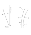
Er3で表される第2の非球面成分δ2は、図9に示すように、光学的中心からレンズ周縁に向けて、レンズの径方向に沿って平均度数αをマイナス側に略直線的に変化させる効果を有する。このため、かかる広焦点レンズ25によれば、ピント合わせできる範囲が広がり焦点距離に幅を持たせることができる。
定数Eの値は、目的とする輻輳と調節との許容範囲を得られるように適宜設定することができる。例えば、定数Eを1.66×10⁻⁵とすれば、瞳孔径5mmとした場合に、立体視における平均度数変化が約0.5Dとなり、段落0023~0025で例示した程度に、輻輳と調節との許容範囲を広げることができる。
なお、図8の(b)に示すように、Δを元の球面Sを基準とする半径aでのz軸方向の高さ(すなわち、元の球面Sからの厚みの増加分)とすると、例えば定数E=7.68×10⁻⁶の場合、aが25mmで、厚みの増加分を示すΔは120μmである。なお、E=Δ/1000/a3が成り立つ(但し、aの単位:mm、Δの単位:μm)。
この広焦点レンズ25では、第2の非球面成分δ2を付加する前のレンズ面内の度数分布がばらついていると、Er3で表される非球面成分δ2による輻輳と調節との許容範囲を広げる効果が、元々レンズが有していた度数分布のばらつきによって相殺され、安定的に発揮されないことが考えられる。このため広焦点レンズ25では、レンズ中央から周縁部に向けて平均度数を一旦、略一定とする目的でレンズ後面52にAr4+Br6+Cr8+Dr10(但し、rはz軸からの距離、A,B,C,Dは定数)で表される第1の非球面成分δ1を付加している。
次に、広焦点レンズ25の設計方法について説明する。まず、処方度数に基づいて広焦点レンズ25の前面53の屈折面および後面52の屈折面を決定する。この決定方法については、周知であるため、ここでは詳述しない。次に、処方度数に基づいて決定されたレンズの後面52の屈折面(元の球面S)に非球面成分を付加する。具体的には、平均度数のばらつきを一旦抑制する第1の非球面成分δ1を付加する第1の非球面成分付加工程と、略一定の傾きで(略直線状に)平均度数を変化させる第2の非球面成分δ2を付加する第2の非球面成分付加工程と、によって後面52の屈折面に非球面成分を付加する。
第1の非球面成分付加工程では、Ar4+Br6+Cr8+Dr10(但し、rはz軸からの距離、A,B,C,Dは定数)で表される第1の非球面成分δ1を求めて、後面52の屈折面に付加する。第1の非球面成分δ1が付加されたレンズでは、図9の破線βで示すように、平均度数をレンズの径方向に沿って、略一定とすることができる。
第1の非球面成分δ1は、下記非球面の式(9)を用いて表される後面52の屈折面形状について、光線追跡によるシミュレーションを行い、度数(詳しくはメリジオナル方向の屈折力とサジタル方向の屈折力との平均である平均度数)の変化を抑制するのに最適な非球面係数A,B,C,Dを求め、これら非球面係数の値から第1の非球面成分δ1を得ることができる。
z=r2/(R1+(R1 2-Kr2)1/2)+Ar4+Br6+Cr8+Dr10 …(9)
ここで、zは後面52におけるサグ値、rはz軸からの距離、R1は頂点曲率半径、A,B,C,Dは定数(非球面係数)である。
z=r2/(R1+(R1 2-Kr2)1/2)+Ar4+Br6+Cr8+Dr10 …(9)
ここで、zは後面52におけるサグ値、rはz軸からの距離、R1は頂点曲率半径、A,B,C,Dは定数(非球面係数)である。
次に第2の非球面成分付加工程では、Er3(但し、rはz軸からの距離、Eは定数)で表される第2の非球面成分δ2を、後面52の屈折面に付加する。この定数Eの絶対値をより大きくすれば、快適に立体視できる範囲(輻輳と調節との許容範囲)を広げることができる。しかしながら、過度に定数Eの絶対値を大きくすれば、得られる像の分解能は低下する。このため定数Eの絶対値が6.40×10⁻⁷~6.40×10⁻⁵の範囲内となるよう、定数Eを設定することが好ましい。
このようにすることで、上記式(7)で定義された広焦点レンズ25の後面52の屈折面形状が決定される。
[実施例]
VR用HMDへの装着を想定した広焦点レンズ(実施例1~4)を作製し、立体表示を観察した際の「見やすさ」および「目の疲れ」について評価した。
VR用HMDへの装着を想定した広焦点レンズ(実施例1~4)を作製し、立体表示を観察した際の「見やすさ」および「目の疲れ」について評価した。
実施例1~4の広焦点レンズに共通するデータは、以下の通りである。
屈折率 1.608、
前面ベースカーブ 4.12、
度数 0.00D、
中心厚 1.80mm
また、各レンズに付加された非球面成分の定数の値は、下記表1の通りである。
屈折率 1.608、
前面ベースカーブ 4.12、
度数 0.00D、
中心厚 1.80mm
また、各レンズに付加された非球面成分の定数の値は、下記表1の通りである。

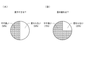
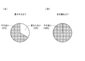
被験者は4名(30~55歳)で、うち2名は眼鏡装用者である。上記実施例の広焦点レンズを備えた立体眼鏡(図5A参照)を装着した状態で、市販の立体映像コンテンツ(立体映画)を視聴した。ディスプレイ表示面と被験者の目との距離は90~120cmとした。所定時間視聴したのち、実施例の広焦点レンズにおける「見やすさ」および「目の疲れ」を、広焦点レンズを備えていない場合との対比で、悪い、やや悪い、変わらない、やや良い、良い、の5区分の何れに該当するかで評価した。
図11,12に実施例3の広焦点レンズの評価結果を示す。図11は、映画の視聴を開始してから30分後に得た結果(回答数4)である。図12は、視聴を開始してから120分後に得た結果(回答数3)である。
これら図11,12によれば、実施例2の広焦点レンズは、「見やすさ」、「目の疲れ」のいずれの項目においても、「やや良い」という結果が半数以上であった。特に視聴時間が長くなった場合に、「やや良い」の割合が高くなった。また、他の実施例1,2,4の広焦点レンズについても、ほぼ同様の結果であった。焦点距離に幅があり虚像の表示範囲を近方側に広げる効果を有する広焦点レンズを用いたことにより、快適に立体視できる立体画像の表示範囲が近方側に拡大したことによる効果と考えられる。
以上のように、本実施形態のHMD21は、左眼用及び右眼用虚像結像光学系4a,4bに対してそれぞれの光軸方向に重ねてそれぞれ配置された左眼用及び右眼用の広焦点レンズ5a、5bに、Ar4+Br6+Cr8+Dr10で表される第1の非球面成分とともに、Er3で表される第2の非球面成分を付加したものである。
本実施形態のHMD21によれば、Er3で表される第2の非球面成分により広焦点レンズ5a、5bの度数が径方向に変化する。すなわち、広焦点レンズ5a、5bの焦点距離には幅があり、虚像が結像する範囲が光軸方向に広がるため、これに対応して輻輳調節矛盾に起因する視覚疲労を被ることなく、快適に立体像を視ることができる輻輳と調節との許容範囲を広げることができる。
図10は、画角の大きいHMD21におけるユーザの視線と広焦点レンズ5a、5bとの関係を示した図である。HMD21の場合、没入感を高めるため広い画角が好まれ、虚像表示面Va,Vbの画角が大きくなる。このため、表示装置3の画面3cから出射して左眼Ea及び右眼Ebに入射する光線群は、図10に示すように、広焦点レンズ5a,5bの中心部のほか、周縁部に近い領域を通る場合がある。ここで本実施形態では、広焦点レンズ25にEr3で表される第2の非球面成分とともに、Ar4+Br6+Cr8+Dr10で表される第1の非球面成分を付加することで、レンズ中心からレンズ周縁部に向けての広い範囲で度数変化の傾きを略一定に維持することができるため、左眼Eaもしくは右眼Ebに入射する光線群が、広焦点レンズ5a,5bのレンズ周縁部に近い領域を通った場合でも、広焦点レンズ5a,5bが虚像結像に与える効果、すなわち輻輳と調節との許容範囲を広げる効果を確保することができる。
<その他の変形例・適用例>
(1)上記実施形態のHMD21はVR用HMDであったが、AR用HMDに広焦点レンズ25を用いることも可能である。
(1)上記実施形態のHMD21はVR用HMDであったが、AR用HMDに広焦点レンズ25を用いることも可能である。
(2)上記実施形態は、広焦点レンズの後面52に第1の非球面成分δ1を付加した例であったが、第1の非球面成分δ1は広焦点レンズの前面53に付加しても良いし、前面53および後面52の両面に付加することも可能である。例えば、前面53にAr4+Br6で表される(この場合定数C、Dの値はゼロである)第1の非球面成分δ1を付加し、更に後面52にCr8+Dr10で表される(この場合定数A、Bの値はゼロである)第1の非球面成分δ1を付加することも可能である。いずれの面に付加する場合であっても、光学的中心からレンズ周縁部にかけての平均度数の変動を抑制することができればよい。
(3)上記実施形態は、広焦点レンズの後面52に第2の非球面成分δ2を付加した例であったが、第2の非球面成分δ2は広焦点レンズの前面53に付加することも可能である。
(4)上記実施形態は、実質的に度の入っていない広焦点レンズを例示しているが、近視、遠視、乱視の少なくとも何れかを矯正するための度数成分が更に設定された広焦点レンズを用いることも可能である。
以上、本発明を実施の形態を用いて説明したが、本発明の技術的範囲は上記実施の形態に記載の範囲には限定されない。上記実施の形態に、多様な変更または改良を加えることが可能であることが当業者に明らかである。その様な変更または改良を加えた形態も本発明の技術的範囲に含まれ得ることが、特許請求の範囲の記載から明らかである。
特許請求の範囲、明細書、および図面中において示した装置、システム、プログラム、および方法における動作、手順、ステップ、および段階等の各処理の実行順序は、特段「より前に」、「先立って」等と明示しておらず、また、前の処理の出力を後の処理で用いるのでない限り、任意の順序で実現しうることに留意すべきである。特許請求の範囲、明細書、および図面中の動作フローに関して、便宜上「まず、」、「次に、」等を用いて説明したとしても、この順で実施することが必須であることを意味するものではない。
1,21…ヘッドマウントディスプレイ(HMD、VR用HMD)、2…フレーム、3…表示装置、3a…左眼用画像、3b…右眼用画像、3c…画面、4a…左眼用虚像結像光学系(虚像結像光学系)、4b…右眼用虚像結像光学系(虚像結像光学系)、4a0,4b0…光軸、5a…左眼用広焦点レンズ(広焦点レンズ)、5b…右眼用広焦点レンズ(広焦点レンズ)、5a0,5b0…光学的中心、6a,6b…アクチュエータ、11…ヘッドマウントディスプレイ(HMD、AR用HMD)、12…フレーム、13a…左眼用表示装置、13b…右眼用表示装置、17a…左眼用ハーフミラー、17b…右眼用ハーフミラー、25…広焦点レンズ、52…後面、53…前面、Am…領域、As…領域、Av…範囲、D…ディスプレイ表示面、Ea…左眼、Eb…右眼、L…中心線、La,Lb…主視線、Va,Vb…虚像表示面、Δ…シフト量、δ1,δ2…非球面成分
Claims (10)
- 左眼用及び右眼用画像を画面上に表示する表示装置と、
前記画面上の左眼用及び右眼用画像に対してそれぞれ配置される左眼用及び右眼用虚像結像光学系と、
前記左眼用及び右眼用虚像結像光学系に対してそれぞれの光軸方向に重ねてそれぞれ配置される、焦点距離が負で幅を有する左眼用及び右眼用広焦点レンズと、
を備えるヘッドマウントディスプレイ。 - 前記左眼用及び右眼用広焦点レンズの光学的中心は、それぞれ、前記左眼用及び右眼用虚像結像光学系の光学的中心に対して左右方向に関する両レンズの中心側にシフトして配置される、請求項1に記載のヘッドマウントディスプレイ。
- 前記左眼用及び右眼用広焦点レンズのそれぞれの光学的中心の前記左眼用及び右眼用虚像結像光学系のうちの重ねられるレンズの光軸に対するシフト量Δは、前記左眼用及び右眼用虚像結像光学系の左右方向に関する間隔P、前記左眼用及び右眼用広焦点レンズとユーザの左眼及び右眼の瞳孔との離間距離d、及び前記左眼用及び右眼用広焦点レンズと前記左眼用及び右眼用虚像結像光学系により結像される虚像との離間距離l0、ユーザの左眼及び右眼の瞳孔とユーザの手前の作業位置との離間距離Qに対して、Δ=Pd/2Q~Pd/2(l0+d)の範囲内である、請求項2に記載のヘッドマウントディスプレイ。
- 前記左眼用及び右眼用広焦点レンズをそれぞれ前記左眼用及び右眼用虚像結像光学系に対して左右方向に変位する変位機構をさらに備える、請求項3に記載のヘッドマウントディスプレイ。
- 前記表示装置は、前記左眼用及び右眼用画像をそれぞれ表示する左眼用及び右眼用画面を有し、
前記左眼用虚像結像光学系の前記左眼用画面に対する逆側且つユーザの左眼の前方に配置される左眼用ハーフミラーと、
前記右眼用虚像結像光学系の前記右眼用画面に対する逆側且つユーザの右眼の前方に配置される右眼用ハーフミラーと、
をさらに備える、請求項1から4のいずれか一項に記載のヘッドマウントディスプレイ。 - 前記左眼用及び右眼用広焦点レンズとして用いられる広焦点レンズは、レンズの光学的中心を通る前後方向の軸をz軸、レンズの後方に向かう方向をz軸の正方向としたとき、レンズの前面および後面の少なくとも一方のz座標値に、Ar4+Br6+Cr8+Dr10(但し、rはz軸からの距離、A,B,C,Dは定数)で表され、前記光学的中心からレンズ周縁部にかけての平均度数の変動を抑制する第1の非球面成分が付加されているとともに、
レンズの前面もしくは後面の何れかのz座標値に、Er3(但し、Eは定数)で表される第2の非球面成分が付加されている、請求項1に記載のヘッドマウントディスプレイ。 - 前記広焦点レンズは、前記光学的中心からレンズ周縁部に向けて平均度数がマイナス側に漸次変化する、請求項6に記載のヘッドマウントディスプレイ。
- 前記広焦点レンズは、近視、遠視、乱視の少なくとも何れかを矯正するための度数成分が更に設定されている、請求項7に記載のヘッドマウントディスプレイ。
- 前記広焦点レンズを前記虚像結像光学系と一体に構成した、請求項1に記載のヘッドマウントディスプレイ。
- 請求項6に記載の広焦点レンズの設計方法であって、
前記光学的中心を通る前後方向の軸をz軸、レンズの後方に向かう方向をz軸の正方向としたとき、処方度数に基づいて決定されるレンズの前面および後面の少なくとも一方のz座標値に、Ar4+Br6+Cr8+Dr10(但し、rはz軸からの距離、A,B,C,Dは定数)で表され、前記光学的中心からレンズ周縁部にかけての平均度数の変動を抑制する第1の非球面成分を付加する第1の非球面成分付加工程と、
前記レンズの前面もしくは後面の何れかのz座標値に、Er3(但し、Eは定数)で表される第2の非球面成分を付加する第2の非球面成分付加工程と、を備えている、広焦点レンズの設計方法。
Priority Applications (4)
| Application Number | Priority Date | Filing Date | Title |
|---|---|---|---|
| US16/617,689 US11740459B2 (en) | 2018-10-15 | 2019-07-22 | Head-mounted display and method for designing wide-focus lens to be used for the head-mounted display |
| CN201980002658.7A CN111328380B (zh) | 2018-10-15 | 2019-07-22 | 头戴式显示器以及头戴式显示器中使用的广焦点透镜的设计方法 |
| EP19805873.7A EP3663835B1 (en) | 2018-10-15 | 2019-07-22 | Head-mounted display and method for designing wide-focus lens used in same |
| JP2020502732A JP7533858B2 (ja) | 2018-10-15 | 2019-07-22 | ヘッドマウントディスプレイおよびこれに用いられる広焦点レンズの設計方法 |
Applications Claiming Priority (4)
| Application Number | Priority Date | Filing Date | Title |
|---|---|---|---|
| JP2018-194640 | 2018-10-15 | ||
| JP2018194640 | 2018-10-15 | ||
| JP2019001404 | 2019-01-08 | ||
| JP2019-001404 | 2019-01-08 |
Publications (1)
| Publication Number | Publication Date |
|---|---|
| WO2020079906A1 true WO2020079906A1 (ja) | 2020-04-23 |
Family
ID=70283863
Family Applications (1)
| Application Number | Title | Priority Date | Filing Date |
|---|---|---|---|
| PCT/JP2019/028635 Ceased WO2020079906A1 (ja) | 2018-10-15 | 2019-07-22 | ヘッドマウントディスプレイおよびこれに用いられる広焦点レンズの設計方法 |
Country Status (5)
| Country | Link |
|---|---|
| US (1) | US11740459B2 (ja) |
| EP (1) | EP3663835B1 (ja) |
| JP (1) | JP7533858B2 (ja) |
| CN (1) | CN111328380B (ja) |
| WO (1) | WO2020079906A1 (ja) |
Cited By (2)
| Publication number | Priority date | Publication date | Assignee | Title |
|---|---|---|---|---|
| CN112068326A (zh) * | 2020-09-17 | 2020-12-11 | 京东方科技集团股份有限公司 | 3d显示装置 |
| JP2024174671A (ja) * | 2023-06-05 | 2024-12-17 | 国立大学法人東京農工大学 | 立体メガネ |
Families Citing this family (7)
| Publication number | Priority date | Publication date | Assignee | Title |
|---|---|---|---|---|
| CN112384840A (zh) * | 2018-07-11 | 2021-02-19 | 华为技术有限公司 | 用于使摄像头设备的光轴位移的可拆卸光学结构 |
| CN114185169B (zh) * | 2020-08-25 | 2024-03-05 | 成都理想境界科技有限公司 | 一种散射屏参数优化方法、散射屏及可读存储介质 |
| CN112255789B (zh) * | 2020-10-21 | 2022-04-22 | 京东方科技集团股份有限公司 | 虚拟现实显示光学系统及虚拟现实设备 |
| CN113671607B (zh) * | 2020-12-14 | 2022-10-25 | 明月镜片股份有限公司 | 一种双面非球面镜片及其设计方法 |
| CN115128802B (zh) * | 2021-03-24 | 2025-09-23 | 群创光电股份有限公司 | 影像的显示方法 |
| CN115590733A (zh) * | 2021-07-08 | 2023-01-13 | 华为技术有限公司(Cn) | 一种视力训练方法及装置 |
| CN117795396A (zh) * | 2021-08-20 | 2024-03-29 | 索尼集团公司 | 显示设备和显示方法 |
Citations (8)
| Publication number | Priority date | Publication date | Assignee | Title |
|---|---|---|---|---|
| JPH09297282A (ja) | 1996-05-01 | 1997-11-18 | Nippon Telegr & Teleph Corp <Ntt> | ヘッドマウントディスプレイ装置 |
| JP2005227682A (ja) * | 2004-02-16 | 2005-08-25 | Victor Co Of Japan Ltd | 立体画像表示装置 |
| JP2012078670A (ja) * | 2010-10-04 | 2012-04-19 | Hoya Corp | 立体映像観察用眼鏡 |
| WO2015137165A1 (ja) | 2014-03-14 | 2015-09-17 | 株式会社ソニー・コンピュータエンタテインメント | ヘッドマウントディスプレイ |
| JP2016024273A (ja) * | 2014-07-17 | 2016-02-08 | 株式会社ソニー・コンピュータエンタテインメント | 立体画像提示装置、立体画像提示方法、およびヘッドマウントディスプレイ |
| US20160327793A1 (en) * | 2015-05-07 | 2016-11-10 | Shinyoptics Corp. | Autofocus head mounted display device |
| JP2016206338A (ja) | 2015-04-20 | 2016-12-08 | 伊藤光学工業株式会社 | 視力矯正用レンズの設計方法及び視力矯正用レンズ |
| JP2018084788A (ja) * | 2016-11-25 | 2018-05-31 | 伊藤光学工業株式会社 | 累進屈折力レンズの設計方法及び累進屈折力レンズ |
Family Cites Families (13)
| Publication number | Priority date | Publication date | Assignee | Title |
|---|---|---|---|---|
| US4577942A (en) * | 1983-02-22 | 1986-03-25 | Optical Systems International, Inc. | Laminated high correction eyeglass lens |
| JPH10282448A (ja) | 1997-04-04 | 1998-10-23 | Minolta Co Ltd | ディスプレイ |
| JP2002031776A (ja) | 2000-07-14 | 2002-01-31 | Canon Inc | 表示装置 |
| JP2003241081A (ja) * | 2002-02-20 | 2003-08-27 | Fuji Photo Optical Co Ltd | 全長の短い単焦点レンズ |
| US20130261744A1 (en) * | 2010-06-01 | 2013-10-03 | Elenza, Inc. | Implantable ophthalmic device with an aspheric lens |
| US9734622B2 (en) * | 2010-06-01 | 2017-08-15 | Vladimir Vaganov | 3D digital painting |
| US8953242B2 (en) * | 2011-03-31 | 2015-02-10 | Honeywell International Inc. | Varible focus stereoscopic display system and method |
| WO2015195549A1 (en) * | 2014-06-16 | 2015-12-23 | Vladimir Vaganov | 3d digital painting |
| TW201617690A (zh) * | 2014-08-13 | 2016-05-16 | 阿爾發普瑞米特斯股份有限公司 | 用於智慧型眼用佩戴品之處方鏡片 |
| US9681804B2 (en) * | 2015-01-12 | 2017-06-20 | X Development Llc | Hybrid lens system for head wearable display |
| CN106353892B (zh) * | 2015-07-24 | 2020-02-07 | 爱博诺德(北京)医疗科技股份有限公司 | 一种眼内镜 |
| US10551636B2 (en) * | 2015-07-24 | 2020-02-04 | Eyebright Medical Technology (Beijing) Co., Ltd. | Vision correction lens and method for preparation of the same |
| CN109725418B (zh) * | 2017-10-30 | 2020-10-16 | 华为技术有限公司 | 显示设备、用于调整显示设备的图像呈现的方法及装置 |
-
2019
- 2019-07-22 CN CN201980002658.7A patent/CN111328380B/zh active Active
- 2019-07-22 EP EP19805873.7A patent/EP3663835B1/en active Active
- 2019-07-22 US US16/617,689 patent/US11740459B2/en active Active
- 2019-07-22 WO PCT/JP2019/028635 patent/WO2020079906A1/ja not_active Ceased
- 2019-07-22 JP JP2020502732A patent/JP7533858B2/ja active Active
Patent Citations (8)
| Publication number | Priority date | Publication date | Assignee | Title |
|---|---|---|---|---|
| JPH09297282A (ja) | 1996-05-01 | 1997-11-18 | Nippon Telegr & Teleph Corp <Ntt> | ヘッドマウントディスプレイ装置 |
| JP2005227682A (ja) * | 2004-02-16 | 2005-08-25 | Victor Co Of Japan Ltd | 立体画像表示装置 |
| JP2012078670A (ja) * | 2010-10-04 | 2012-04-19 | Hoya Corp | 立体映像観察用眼鏡 |
| WO2015137165A1 (ja) | 2014-03-14 | 2015-09-17 | 株式会社ソニー・コンピュータエンタテインメント | ヘッドマウントディスプレイ |
| JP2016024273A (ja) * | 2014-07-17 | 2016-02-08 | 株式会社ソニー・コンピュータエンタテインメント | 立体画像提示装置、立体画像提示方法、およびヘッドマウントディスプレイ |
| JP2016206338A (ja) | 2015-04-20 | 2016-12-08 | 伊藤光学工業株式会社 | 視力矯正用レンズの設計方法及び視力矯正用レンズ |
| US20160327793A1 (en) * | 2015-05-07 | 2016-11-10 | Shinyoptics Corp. | Autofocus head mounted display device |
| JP2018084788A (ja) * | 2016-11-25 | 2018-05-31 | 伊藤光学工業株式会社 | 累進屈折力レンズの設計方法及び累進屈折力レンズ |
Non-Patent Citations (6)
| Title |
|---|
| G. MIKULAZ. JAROSZEWICZA. KOLODZIEJCZYKK. PETELCZYCM. SYPEK: "Images with extended focal depth by means of lenses with radial and angular modulation", OPT. EXPRESS, vol. 15, no. 15, 2007, pages 9184 - 9193 |
| J. SOCHACKIA. KOLODZIEJCZYKZ. JAROSZEWICZS. BARA: "Nonparaxial design of generalized axicons", APPL. OPT., vol. 31, 1992, pages 5326 - 5330, XP000294493, DOI: 10.1364/AO.31.005326 |
| N. DAVIDSONA. A. FRIESEME. HASMAN: "Holographic axilens: high resolution and long focal depth", OPT. LETT., vol. 16, 1991, pages 523 - 525, XP000179792 |
| N. PADMANABANR. KONRADT. STRAMERE.A. COOPERG. WETZSTEIN: "Optimizing virtual reality for all users through gaze-contingent and adaptive focus displays", PNAS, vol. 114, 2017, pages 2183 - 2188, XP055402339, DOI: 10.1073/pnas.1617251114 |
| T. SHIBATAJ. KIMD. M. HOFFMANM. S. BANKS: "The zone of comfort: Predicting visual discomfort with stereo displays", J. VISION, vol. 11, no. 8, 2011, pages 1 - 29, XP055171846, DOI: 10.1167/11.8.11 |
| X. HUH. HUA: "High-resolution optical see-through multi-focal-plane head-mounted display using freeform optics", OPT. EXPRESS, vol. 22, 2014, pages 13896 - 13903 |
Cited By (4)
| Publication number | Priority date | Publication date | Assignee | Title |
|---|---|---|---|---|
| CN112068326A (zh) * | 2020-09-17 | 2020-12-11 | 京东方科技集团股份有限公司 | 3d显示装置 |
| CN112068326B (zh) * | 2020-09-17 | 2022-08-09 | 京东方科技集团股份有限公司 | 3d显示装置 |
| JP2024174671A (ja) * | 2023-06-05 | 2024-12-17 | 国立大学法人東京農工大学 | 立体メガネ |
| JP7842409B2 (ja) | 2023-06-05 | 2026-04-08 | 国立大学法人東京農工大学 | 立体メガネ |
Also Published As
| Publication number | Publication date |
|---|---|
| JPWO2020079906A1 (ja) | 2021-09-02 |
| US20210286177A1 (en) | 2021-09-16 |
| JP7533858B2 (ja) | 2024-08-14 |
| CN111328380A (zh) | 2020-06-23 |
| EP3663835A4 (en) | 2021-06-23 |
| EP3663835A1 (en) | 2020-06-10 |
| EP3663835C0 (en) | 2025-07-09 |
| EP3663835B1 (en) | 2025-07-09 |
| US11740459B2 (en) | 2023-08-29 |
| CN111328380B (zh) | 2023-04-04 |
Similar Documents
| Publication | Publication Date | Title |
|---|---|---|
| JP7533858B2 (ja) | ヘッドマウントディスプレイおよびこれに用いられる広焦点レンズの設計方法 | |
| JP4155343B2 (ja) | 二つの光景からの光を観察者の眼へ代替的に、あるいは同時に導くための光学系 | |
| CN107407812B (zh) | 图像显示装置 | |
| KR101916079B1 (ko) | 하나 또는 그 이상의 프레넬 렌즈를 수반하는 헤드 장착 디스플레이 장치 | |
| JP6859362B2 (ja) | 頭部装着型仮想現実表示装置 | |
| JP5290092B2 (ja) | 眼鏡型画像表示装置 | |
| CN107209381B (zh) | 用于可头戴显示器的混合透镜系统 | |
| US7992996B2 (en) | Spectacles-type image display device | |
| CN111373307B (zh) | 立体眼镜、该立体眼镜中使用的眼镜镜片的设计方法以及立体图像的观察方法 | |
| US20070236800A1 (en) | Imaging systems for eyeglass-based display devices | |
| CN113341567A (zh) | 一种双焦面光波导近眼显示光学系统 | |
| JP2020024363A (ja) | 表示装置 | |
| JP7177356B2 (ja) | パーソナルディスプレイ用の接眼レンズ及びこのような接眼レンズを含むパーソナルディスプレイ | |
| CN115004084B (zh) | 头戴式显示器以及在该头戴式显示器中使用的虚像成像透镜 | |
| WO2020026749A1 (ja) | 表示装置 | |
| JP2019179083A (ja) | 画像表示装置 | |
| JP7842409B2 (ja) | 立体メガネ | |
| JP3833207B2 (ja) | 表示装置 | |
| JP2025154747A (ja) | 虚像表示装置及び虚像表示方法 | |
| JP2025512047A (ja) | 眼科機器、及び、レンズ要素 | |
| JP2004226958A (ja) | 立体観察装置 |
Legal Events
| Date | Code | Title | Description |
|---|---|---|---|
| ENP | Entry into the national phase |
Ref document number: 2019805873 Country of ref document: EP Effective date: 20191128 |
|
| ENP | Entry into the national phase |
Ref document number: 2020502732 Country of ref document: JP Kind code of ref document: A |
|
| NENP | Non-entry into the national phase |
Ref country code: DE |
|
| WWG | Wipo information: grant in national office |
Ref document number: 2019805873 Country of ref document: EP |