WO2020079916A1 - プログラム及び情報処理方法 - Google Patents
プログラム及び情報処理方法 Download PDFInfo
- Publication number
- WO2020079916A1 WO2020079916A1 PCT/JP2019/029688 JP2019029688W WO2020079916A1 WO 2020079916 A1 WO2020079916 A1 WO 2020079916A1 JP 2019029688 W JP2019029688 W JP 2019029688W WO 2020079916 A1 WO2020079916 A1 WO 2020079916A1
- Authority
- WO
- WIPO (PCT)
- Prior art keywords
- data
- determination
- display
- accident
- display area
- Prior art date
- Legal status (The legal status is an assumption and is not a legal conclusion. Google has not performed a legal analysis and makes no representation as to the accuracy of the status listed.)
- Ceased
Links
Images



Classifications
-
- H—ELECTRICITY
- H04—ELECTRIC COMMUNICATION TECHNIQUE
- H04W—WIRELESS COMMUNICATION NETWORKS
- H04W4/00—Services specially adapted for wireless communication networks; Facilities therefor
- H04W4/90—Services for handling of emergency or hazardous situations, e.g. earthquake and tsunami warning systems [ETWS]
-
- G—PHYSICS
- G06—COMPUTING OR CALCULATING; COUNTING
- G06Q—INFORMATION AND COMMUNICATION TECHNOLOGY [ICT] SPECIALLY ADAPTED FOR ADMINISTRATIVE, COMMERCIAL, FINANCIAL, MANAGERIAL OR SUPERVISORY PURPOSES; SYSTEMS OR METHODS SPECIALLY ADAPTED FOR ADMINISTRATIVE, COMMERCIAL, FINANCIAL, MANAGERIAL OR SUPERVISORY PURPOSES, NOT OTHERWISE PROVIDED FOR
- G06Q40/00—Finance; Insurance; Tax strategies; Processing of corporate or income taxes
- G06Q40/08—Insurance
-
- G—PHYSICS
- G06—COMPUTING OR CALCULATING; COUNTING
- G06Q—INFORMATION AND COMMUNICATION TECHNOLOGY [ICT] SPECIALLY ADAPTED FOR ADMINISTRATIVE, COMMERCIAL, FINANCIAL, MANAGERIAL OR SUPERVISORY PURPOSES; SYSTEMS OR METHODS SPECIALLY ADAPTED FOR ADMINISTRATIVE, COMMERCIAL, FINANCIAL, MANAGERIAL OR SUPERVISORY PURPOSES, NOT OTHERWISE PROVIDED FOR
- G06Q50/00—Information and communication technology [ICT] specially adapted for implementation of business processes of specific business sectors, e.g. utilities or tourism
- G06Q50/10—Services
-
- G—PHYSICS
- G07—CHECKING-DEVICES
- G07C—TIME OR ATTENDANCE REGISTERS; REGISTERING OR INDICATING THE WORKING OF MACHINES; GENERATING RANDOM NUMBERS; VOTING OR LOTTERY APPARATUS; ARRANGEMENTS, SYSTEMS OR APPARATUS FOR CHECKING NOT PROVIDED FOR ELSEWHERE
- G07C5/00—Registering or indicating the working of vehicles
- G07C5/008—Registering or indicating the working of vehicles communicating information to a remotely located station
-
- G—PHYSICS
- G07—CHECKING-DEVICES
- G07C—TIME OR ATTENDANCE REGISTERS; REGISTERING OR INDICATING THE WORKING OF MACHINES; GENERATING RANDOM NUMBERS; VOTING OR LOTTERY APPARATUS; ARRANGEMENTS, SYSTEMS OR APPARATUS FOR CHECKING NOT PROVIDED FOR ELSEWHERE
- G07C5/00—Registering or indicating the working of vehicles
- G07C5/08—Registering or indicating performance data other than driving, working, idle, or waiting time, with or without registering driving, working, idle or waiting time
- G07C5/0841—Registering performance data
- G07C5/085—Registering performance data using electronic data carriers
-
- G—PHYSICS
- G07—CHECKING-DEVICES
- G07C—TIME OR ATTENDANCE REGISTERS; REGISTERING OR INDICATING THE WORKING OF MACHINES; GENERATING RANDOM NUMBERS; VOTING OR LOTTERY APPARATUS; ARRANGEMENTS, SYSTEMS OR APPARATUS FOR CHECKING NOT PROVIDED FOR ELSEWHERE
- G07C5/00—Registering or indicating the working of vehicles
- G07C5/08—Registering or indicating performance data other than driving, working, idle, or waiting time, with or without registering driving, working, idle or waiting time
- G07C5/0841—Registering performance data
- G07C5/085—Registering performance data using electronic data carriers
- G07C5/0866—Registering performance data using electronic data carriers the electronic data carrier being a digital video recorder in combination with video camera
-
- G—PHYSICS
- G08—SIGNALLING
- G08G—TRAFFIC CONTROL SYSTEMS
- G08G1/00—Traffic control systems for road vehicles
- G08G1/01—Detecting movement of traffic to be counted or controlled
- G08G1/0104—Measuring and analyzing of parameters relative to traffic conditions
- G08G1/0108—Measuring and analyzing of parameters relative to traffic conditions based on the source of data
- G08G1/0112—Measuring and analyzing of parameters relative to traffic conditions based on the source of data from the vehicle, e.g. floating car data [FCD]
-
- G—PHYSICS
- G08—SIGNALLING
- G08G—TRAFFIC CONTROL SYSTEMS
- G08G1/00—Traffic control systems for road vehicles
- G08G1/01—Detecting movement of traffic to be counted or controlled
- G08G1/0104—Measuring and analyzing of parameters relative to traffic conditions
- G08G1/0125—Traffic data processing
- G08G1/0129—Traffic data processing for creating historical data or processing based on historical data
-
- G—PHYSICS
- G08—SIGNALLING
- G08G—TRAFFIC CONTROL SYSTEMS
- G08G1/00—Traffic control systems for road vehicles
- G08G1/01—Detecting movement of traffic to be counted or controlled
- G08G1/0104—Measuring and analyzing of parameters relative to traffic conditions
- G08G1/0125—Traffic data processing
- G08G1/0133—Traffic data processing for classifying traffic situation
-
- G—PHYSICS
- G08—SIGNALLING
- G08G—TRAFFIC CONTROL SYSTEMS
- G08G1/00—Traffic control systems for road vehicles
- G08G1/01—Detecting movement of traffic to be counted or controlled
- G08G1/017—Detecting movement of traffic to be counted or controlled identifying vehicles
- G08G1/0175—Detecting movement of traffic to be counted or controlled identifying vehicles by photographing vehicles, e.g. when violating traffic rules
-
- G—PHYSICS
- G08—SIGNALLING
- G08G—TRAFFIC CONTROL SYSTEMS
- G08G1/00—Traffic control systems for road vehicles
- G08G1/01—Detecting movement of traffic to be counted or controlled
- G08G1/04—Detecting movement of traffic to be counted or controlled using optical or ultrasonic detectors
-
- G—PHYSICS
- G08—SIGNALLING
- G08G—TRAFFIC CONTROL SYSTEMS
- G08G1/00—Traffic control systems for road vehicles
- G08G1/01—Detecting movement of traffic to be counted or controlled
- G08G1/052—Detecting movement of traffic to be counted or controlled with provision for determining speed or overspeed
-
- H—ELECTRICITY
- H04—ELECTRIC COMMUNICATION TECHNIQUE
- H04W—WIRELESS COMMUNICATION NETWORKS
- H04W4/00—Services specially adapted for wireless communication networks; Facilities therefor
- H04W4/30—Services specially adapted for particular environments, situations or purposes
- H04W4/40—Services specially adapted for particular environments, situations or purposes for vehicles, e.g. vehicle-to-pedestrians [V2P]
- H04W4/44—Services specially adapted for particular environments, situations or purposes for vehicles, e.g. vehicle-to-pedestrians [V2P] for communication between vehicles and infrastructures, e.g. vehicle-to-cloud [V2C] or vehicle-to-home [V2H]
Definitions
- the present invention relates to a program and an information processing method to be executed by an information processing device.
- an emergency notification device mounted on an accident vehicle is composed of a GPS receiver, a gyro, a vehicle speed sensor, a collision sensor, and a public mobile phone (radio device).
- a vehicle emergency normal system is disclosed that accumulates vehicle speed information at each vehicle speed change or at fixed time intervals and transmits the site location information and vehicle speed information to an emergency center by data communication when an accident occurs.
- the emergency center is provided with a means for displaying the received site position and the traveling locus on the map in a superimposed manner, and when displaying the traveling locus, displays the traveling locus marks colored in several stages according to the vehicle speed information. It is supposed to be displayed on the map.
- Patent Document 2 discloses a drive recorder device system that includes a drive recorder device mounted on a vehicle and a vehicle management center that collects data from the drive recorder device via a communication line.
- a drive recorder device is mounted on a vehicle equipped with a road-to-vehicle communication device that is installed at an intersection with a traffic light or the like and performs wireless communication with a roadside device that acquires lighting information of the traffic light, and road-to-vehicle communication is performed.
- Patent Document 3 discloses an insurance company system that receives a report of a car accident between cars including the insured's fault rate. Patent Document 3 describes that a person in charge of an insurance company may calculate and input the accident fault rate by referring to a case database, a court case database, or the like.
- Patent Document 4 accident form analysis data is created from image information of an accident recorded by a digital video camera, and the data is collated with a database in which past negligence ratio precedents have been converted into data using a computer.
- a digital video camera fault rate assessment system for performing an assessment is disclosed.
- a basic negligence ratio is determined based on accident form analysis data and various kinds of past negligence ratio precedent data (collision partner data, accident site road structure data, etc.), and further correction factor data.
- a technique for determining a fault rate evaluation based on the above is disclosed.
- the present invention has been made in view of the above-described circumstances, and provides a program and an information processing method capable of objectively and easily confirming the cause of occurrence by visualizing an accident situation in a car accident. With the goal.
- a program which is one embodiment of the present invention, receives a plurality of data used for determining an accident situation in an information processing device and determines an accident situation (items illustrated in FIG. 5) based on the plurality of data.
- a display screen of a determination screen including a first display area for displaying the determination item and the determination result, and a second display area for displaying the evidence data in the determination item having evidence data for the determination result,
- the program controls the display so as to display a still image of a part of the moving image in association with the determination item. May be further executed by the information processing apparatus.
- the program receives a second command based on a user operation for a predetermined still image in the second display area, and displays a reproduction screen for reproducing a moving image for the predetermined still image based on the second command.
- the information processing apparatus may further cause the information processing apparatus to execute display control.
- the moving image may be different depending on the determination item.
- a portion related to the determination result may be highlighted in the moving image.
- the program accepts a third command based on a user operation on the item indicating the contact point, and based on the third command, a clock is received. Even if the information processing apparatus is further caused to perform processing, the vehicle is displayed in an overlapping manner, the front of the vehicle is displayed in the 12 o'clock direction of the timepiece, and the contact point is displayed on the vehicle. good.
- the program includes a third display area for displaying a basic error rate determined on the determination screen using the plurality of data and past standardized case data or standardized data based on the standardized case, and the case data.
- Display control is performed so that a predetermined UI component relating to display is displayed, a fourth command based on a user operation on the predetermined UI component is accepted, and a case used for the determination of the basic negligence ratio based on the fourth command.
- the information processing apparatus may further cause the information processing apparatus to perform display control so as to display data.
- the program further controls the information processing device to perform display control so that the determination screen is displayed so as to include a fourth display area that displays map data that describes the accident situation determined based on the plurality of data. You may let it run.
- the program may further cause the information processing apparatus to execute a process of receiving a fifth command based on a user operation for modifying the determination result and reflecting the modification of the determination result based on the fifth command.
- An information processing method receives a plurality of data used for determining an accident situation, and displays a plurality of determination items and a determination result for determining the accident situation based on the plurality of data.
- One display area and a determination screen including a second display area for displaying the evidence data in a determination item having evidence data for the determination result are displayed and controlled on a display device, and a predetermined determination result in the first display area is displayed.
- An instruction based on a user operation is accepted, and based on the instruction, display control is performed so that evidence data for the predetermined determination result is displayed in the second display area.
- the user can objectively and easily confirm the grounds for determining the accident situation in a car accident.
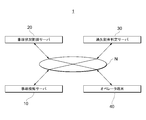
- FIG. 1 is a diagram showing a schematic configuration of an accident processing system according to an embodiment of the present invention.
- the accident processing system 1 according to the present embodiment is intended for use by a non-life insurance company that sells automobile insurance.
- the accident processing system 1 includes an accident detection server 10, an accident situation grasping server 20, a fault rate determination server 30, and an operator terminal 40.
- the accident detection server 10, the accident situation comprehension server 20, the error rate determination server 30, and the operator terminal 40 are connected via a communication network N.
- a plurality of operator terminals 40 may be provided.
- the accident detection server 10, the accident situation grasping server 20, and the negligence ratio determination server 30 are shown one by one, but these servers may be configured by one piece of hardware, Each server may be composed of a plurality of hardware.
- the operator may be referred to as a user.
- the communication network N includes a communication network capable of mutually transmitting and receiving information among the accident detection server 10, the accident situation grasping server 20, the error rate determination server 30, and the operator terminal 40.
- the communication network N is, for example, the Internet, LAN, leased line, telephone line, corporate network, mobile communication network, Bluetooth (registered trademark), WiFi (registered trademark) (Wireless Fidelity), other communication lines, or a combination thereof. It does not matter whether it is wired or wireless.
- Each of the accident detection server 10, the accident situation comprehension server 20, and the negligence ratio determination server 30 is composed of, for example, a computer having high arithmetic processing capability, and executes a predetermined program to cooperate with other servers and the operator terminal 40. Then, after a car accident occurs, a server function for processing information on accident processing such as accident notification, accident situation grasp, and error rate judgment is realized.
- a car accident includes a contact between a car and another object, and the other object is, for example, a car, a bicycle, a motorcycle, a person, an animal, an electric pole, a wall, or the like.
- FIG. 2 is a diagram showing a schematic configuration of the accident detection server 10.
- the accident detection server 10 is an information processing device that acquires various data from a device such as an automobile, detects the occurrence of an accident based on the acquired data, and issues a necessary notification.
- the accident detection server 10 does not necessarily need to acquire various data from a plurality of automobiles, but may acquire various data from at least one automobile device.
- devices such as automobiles include sensors such as a calendar for detecting date and time, a speed sensor for detecting traveling speed, an acceleration sensor for detecting acceleration, a GPS sensor for detecting position, a communication function, a voice recording function, and a video recording function. It has one of the functions, a sensor for measuring millimeter-wave / infrared rays, etc., and a function for detecting the operation / motion of other automobile equipment, and various sensors acquire information at any time.
- Devices such as automobiles use the communication function to collect information (hereinafter referred to as device data) acquired by each sensor at any time or when an abnormal situation such as a change in acceleration more than a predetermined value occurs. It transmits to the detection server 10.
- the accident detection server 10 includes a communication interface 11, a storage unit 12, and a processor 13.
- the communication interface 11 is a hardware module for connecting the accident detection server 10 to the communication network N and communicating with other terminals on the communication network N.
- the communication interface 11 is a modulation / demodulation device such as an ISDN modem, an ADSL modem, a cable modem, an optical modem, and a soft modem.
- the storage unit 12 is a logical device provided by a storage area of a physical device including a computer-readable non-transitory recording medium such as a disk drive or a semiconductor memory (ROM, RAM, etc.).
- the storage unit 12 may be constructed by mapping a plurality of physical devices to one logical device, or may be constructed by mapping one physical device to a plurality of logical devices.
- the storage unit 12 stores various programs including an operating system program and a driver program, and various data used during execution of these programs. Specifically, the storage unit 12 stores various programs P10 to be executed by the processor 13 and device data D10 acquired from the device.
- the processor 13 includes an arithmetic logical operation unit (CPU etc.) for processing arithmetic operations, logical operations, bit operations, etc., and various registers, and executes various programs stored in the storage unit 12 to execute the accident detection server 10 Control each part of.
- the various registers are, for example, a program counter, a data register, an instruction register, a general-purpose register and the like.
- the processor 13 also executes the program P10 to realize an accident detection function of detecting the occurrence of an accident and making a necessary notification.
- the functional units realized by the processor 13 executing the program P10 include a device difference correction unit 131, an accident detection unit 132, and an accident notification unit 133.
- the device difference correction unit 131 corrects the device data received from each device.
- the device data transmitted from each device has individual characteristics (sensor characteristics, difference in data format, etc.). Therefore, the device difference correction unit 131 corrects the received device data into data that can be input to the algorithm executed in the accident detection unit 132.
- the accident detection unit 132 detects an accident by detecting the characteristic at the time of the accident from the device data received from the device by an algorithm constructed based on past accident data and device data.
- the accident notification unit 133 When the accident detection unit 132 detects an accident, the accident notification unit 133 notifies the operator terminal 40 via the communication network N of information indicating that an accident is likely to occur and displays an alert.
- FIG. 3 is a diagram showing a schematic configuration of the accident situation grasping server 20.
- the accident situation grasping server 20 is an information processing apparatus that assists in grasping the accident situation by acquiring necessary information from various systems and visualizing the accident when an accident occurs.
- the accident situation comprehension server 20 acquires device data from the device causing the accident and also acquires the information exemplified below.
- Road information such as sign information and speed limit information: Obtained from the road information system 102 operated by a private company.
- Video data shot by the drive recorder The video data shot by the drive recorder installed in the device of the person involved in the accident is acquired. The video data may be obtained directly from the device of the person involved in the accident, or may be obtained from the drive recorder device system 103 operated by a private service provider. Further, the video data captured by the drive recorder installed in the device that was traveling around the point where the accident occurred at the time of the accident may be acquired from the drive recorder device system 103.
- Map information Obtained from the map information system 104 operated by a private company.
- Weather information Obtained from the weather information system 105 operated by a private or public institution.
- E Contact history information: When the accident party is the insurance contractor of the company, the past contact history is acquired from the damage service system 106.
- the accident situation grasp server 20 includes a communication interface 21, a storage unit 22, and a processor 23.
- the hardware configurations of the communication interface 21, the storage unit 22, and the processor 23 are the same as those of the communication interface 11, the storage unit 12, and the processor 13 described above.
- the storage unit 22 includes various programs P20 to be executed by the processor 23, device data D21 acquired from each device, road information D22 acquired from the road information system 102, and images acquired from the drive recorder device system 103.
- the data D23, the map information D24 acquired from the map information system 104, the weather information D25 acquired from the weather information system 105, the contact history D26 acquired from the damage service system 106, and the processor 23 described later are analyzed.
- the own vehicle behavior data D27 and the other vehicle / surrounding environment data D28 are stored.
- the processor 23 analyzes and visualizes the situation of the accident based on the various information acquired, and realizes the function of supporting the grasp of the situation of the accident.
- the functional units realized by the processor 23 executing the program P20 include the own vehicle driving behavior grasping unit 231, the other vehicle / surrounding environment grasping unit 235, and the display control unit 239.
- the own vehicle driving behavior grasping unit 231 grasps information on the driving behavior of the own vehicle at the time of an accident based on the acquired various data, and stores the grasped information as the own vehicle behavior data D27.
- the own vehicle driving behavior grasping unit 231 is based on the data acquired from the device (own vehicle) that the policyholder side of the in-house insurance was driving in the device data D21, and the road information D22 / map around the accident occurrence point.
- the information D24, the weather information D25, and the contact history D26 the accident situation such as the driving locus of the own vehicle and the speed information is grasped.
- the own vehicle driving behavior grasping unit 231 includes a driving locus extracting unit 232, an acceleration waveform generating unit 233, and a map data matching unit 234.
- the driving locus extraction unit 232 extracts the driving locus of the own vehicle based on the device data D21 acquired from the own vehicle.
- the acceleration waveform generation unit 233 visualizes the waveform data of the acceleration in the own vehicle as a graph based on the device data D21 to identify the behavior of the own vehicle, the impact location, and the like.
- the map data matching unit 234 performs a matching process on the driving locus extracted by the driving locus extraction unit 232 with respect to the road information D22 and the map information D24 around the accident occurrence point, and displays the driving locus by superimposing the driving locus. To visualize.
- the partner vehicle / surrounding environment grasping unit 235 grasps information on the driving behavior of the partner vehicle and information on the surrounding environment based on the acquired various data, and stores the grasped information as the partner vehicle / surrounding environment data D28.
- the other vehicle / surrounding environment grasping unit 235 performs object recognition processing, depth measurement processing, and the like on the video data captured in the own vehicle out of the video data D23, and matches it with the own vehicle behavior data. The speed of the other vehicle is estimated by.
- the other vehicle / surrounding environment grasping unit 235 acquires information such as a signal state at the time of the accident from the video data D23.
- the other vehicle / surrounding environment grasping unit 235 includes a driving locus extracting unit 236, an acceleration waveform generating unit 237, and a map data matching unit 238.
- the operation of each of these units is the same as that of the above-described own vehicle driving behavior grasping unit 231.
- the display control unit 239 displays the driving behavior of the own vehicle grasped by the own vehicle driving behavior grasping unit 231 and the driving behavior of the opponent vehicle grasped by the opponent vehicle / surrounding environment grasping unit 235 and the surrounding environment to the operator terminal 40. Display control to visualize and display in.
- FIG. 4 is a diagram showing a schematic configuration of the error rate determination server 30.
- the negligence rate determination server 30 is an information processing device that acquires the own vehicle behavior data D27 and the partner vehicle / surrounding environment data D28 stored by the accident situation grasping server 20, and determines the negligence rate based on the acquired data. is there.
- the negligence rate determination server 30 includes a communication interface 31, a storage unit 32, and a processor 33.
- the hardware configurations of the communication interface 31, the storage unit 32, and the processor 23 are the same as those of the communication interface 11, the storage unit 12, and the processor 13 described above.
- the storage unit 32 stores various programs P30 to be executed by the processor 33, case data D31 used for determining the error rate, and past case data D32.
- the judicial precedent data D31 is based on a judicial precedent-based negligence ratio, such as the “criterion standard for negligence offset rate in civil traffic litigation” (called “judicial precedent times (registered trademark)”) issued by the precedent case corporation. It is a database.
- the past case data D32 is a database of the error rates in the past cases.
- the processor 33 realizes the function of determining the negligence rate based on the own vehicle behavior data D27 and the partner vehicle / surrounding environment data D28.
- the functional units realized by the processor 33 executing the program P30 include a case information acquisition unit 331, a negligence determination unit 332, and a display control unit 333.
- the case information acquisition unit 331 collates the own vehicle behavior data D27, the other vehicle / surrounding environment data D28 with the case data D31, and identifies the corresponding case (accident classification).
- the error determination unit 332 determines the basic error rate based on the case specified by the case information acquisition unit 331, and also determines the basic error rate according to a command based on a user operation made on the operator terminal 40. Fix it.
- the display control unit 333 performs control for displaying on the operator terminal 40 a negligence ratio determination screen including the determination result by the negligence determination unit 332.
- the display control unit 333 includes an unconfirmed item alert display unit 334 and a reference document presentation unit 335.
- the unconfirmed item alert display unit 334 includes items necessary for determining the error rate or items that may affect the error rate determination (hereinafter, these items are referred to as determination items) and items that the operator has not confirmed. In some cases, display control is performed to call attention.
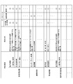
- FIG. 5 is a table exemplifying master data that stores determination items.
- the master data shown in FIG. 5 stores determination items according to categories such as own vehicle behavior, road situation, accident situation, and other vehicle behavior.
- Each determination item is associated with a data source of information related to the determination item (for example, device data such as acceleration information / GPS information, map information, video data captured by a drive recorder, etc.).
- the reference document presenting unit 335 performs display control for causing an operator to refer to documents such as precedents and past cases that correspond to the accident (or have similar situations).
- the negligence splitting determination server 30 it is possible to efficiently and highly fairly determine the negligence percentage based on various data acquired when the accident occurs. Further, according to the negligence ratio determination server 30, since the basis for the determination of the negligence ratio is visualized, the operator can efficiently and easily make the basis for the determination of the negligence ratio.
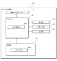
- FIG. 6 is a diagram showing a schematic configuration of the operator terminal 40.
- the operator terminal 40 is a terminal used by an operator who receives a notification of an accident and performs insurance and the like, and is configured by a personal computer (PC), a notebook PC, a tablet terminal, or the like.
- PC personal computer
- notebook PC notebook PC
- tablet terminal or the like.
- the operator terminal 40 is an information processing device including a communication interface 41, a display unit 42, an operation input unit 43, an output unit 44, a storage unit 45, and a processor 46.
- the operator terminal 40 is used as a display device that displays a predetermined screen based on the information received from the accident situation grasping server 20 and the negligence ratio judging server 30, and the accident situation grasping server 20 and It is used as an operation input device for inputting a request, a command, or the like to the negligence ratio determination server 30.
- the communication interface 41 is a hardware module for connecting the operator terminal 40 to the communication network N and communicating with other terminals on the communication network N.
- the communication interface 41 is a modulation / demodulation device such as an ISDN modem, an ADSL modem, a cable modem, an optical modem, and a soft modem.
- the display unit 42 is composed of, for example, a liquid crystal display.
- the operation input unit 43 is an input device such as a keyboard, various operation buttons, a touch panel provided on the display unit 42, and a pointing device such as a mouse.
- the output unit 44 is an output device such as a printer.
- the storage unit 45 is, for example, a logical device provided by a storage area of a physical device.
- the physical device is, for example, a computer-readable non-transitory recording medium such as a disk drive or a semiconductor memory (ROM, RAM, etc.).
- the storage unit 45 may be constructed by mapping a plurality of physical devices to one logical device, or may be constructed by mapping one physical device to a plurality of logical devices. Further, the storage unit 45 may be a USB memory, an SD (registered trademark) card, or the like.
- the storage unit 45 stores an operating system program, a driver program, various data, and the like. More specifically, the storage unit 45 causes the processor 46 to execute the communication with the accident situation grasp server 20 and the negligence ratio determination server 30, and the information transmitted from these servers is displayed on the display unit 42 in a predetermined format. The program P40 to be displayed is stored.
- the processor 46 is composed of an arithmetic logic operation unit (such as a CPU) that processes arithmetic operations, logical operations, bit operations and the like and various registers, and executes various programs stored in the storage unit 45 to execute the various programs of the operator terminal 40. Centrally control each part.
- the various registers are, for example, a program counter, a data register, an instruction register, a general-purpose register and the like.
- the functional unit realized by the processor 46 executing the program P40 includes a display control unit 461 that causes the display unit 42 to display the information transmitted from the accident situation grasping server 20 or the negligence ratio determination server 30 in a predetermined format. Including.
- the processor 46 when the user operates the operation input unit 43, the processor 46 outputs a command corresponding to the user operation to each unit of the operator terminal 40 to execute the process. Further, the processor 46, while the operator terminal 40 is accessing the accident situation comprehension server 20 or the negligence rate determination server 30, sends a message to the screen transmitted from the accident situation comprehension server 20 or the negligence rate determination server 30. When an operation is performed, a signal indicating an instruction corresponding to the user operation is transmitted to the accident situation grasp server 20 or the negligence rate determination server 30 to request execution of the instruction.
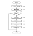
- FIG. 7 is a flowchart showing the operation of the accident detection server 10.
- the accident detection server 10 acquires device data (step S10) and analyzes the acquired device data to perform accident detection processing (step S11, FIG. 1).
- step S12 determines that an accident has occurred (step S12: Yes)
- step S12: No determines that no accident has occurred
- the accident situation grasping server 20 When an accident is reported, the accident situation grasping server 20 causes the accident data, such as device data, road information, video data, map information, weather information, contact history information, etc., transmitted from the device which is the party of the accident to be related. Is acquired (step S14, see FIG. 2). Subsequently, the accident situation grasping server 20 analyzes the accident based on the acquired information (step S15). Then, the accident situation grasping server 20 stores the analysis result (step S16).
- the accident data such as device data, road information, video data, map information, weather information, contact history information, etc.
- the analysis result stored in the accident situation grasp server 20 is transmitted to the operator terminal 40 upon request from the operator terminal 40 and displayed in a predetermined format.
- the operator can display the information on the accident in which the contractor is a party on the operator terminal 40, for example, by searching with the insurance policy number or by transitioning from another system having the contractor information.
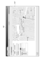
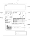
- FIG. 8 to 9 are schematic views illustrating screens displayed on the operator terminal 40.
- FIG. 8 is a schematic diagram illustrating a traveling situation detail screen.
- FIG. 9 is a schematic diagram illustrating a driving situation detail screen.
- the travel information detail screen M1 shown in FIG. 8 includes a user information display area m10 in which information about insurance policyholders is displayed, an accident location display area m11 in which information indicating an accident occurrence point is displayed, and a drive of the own vehicle.
- the error rate determination support button m15 and a driving information display area m16 for displaying driving information of the driver are included.
- the impact information display area m14 is provided with an input location display area that represents the location of impact input to the vehicle.
- the host vehicle In the input point display area, the host vehicle is displayed in a superimposed manner on the watch so that the 12 o'clock direction of the watch is in front of the host vehicle, and the input direction of the impact (that is, the contact point of the opponent vehicle) is marked. It As a result, in the insurance industry, the expression "what time is the direction of the shock” is used as if it were a shock input, so that the direction of the shock can be easily visually grasped using the input position display area.
- a new tab or window opens and the travel information detail screen M2 shown in FIG. 9 is displayed.
- An enlarged trajectory display area m21 is provided on the travel information detail screen M2 shown in FIG.
- a new tab or window opens and the accident situation screen M3 shown in FIG. 10 is displayed.
- the accident situation screen M3 shown in FIG. 10 is provided with an animation display area m31 for explaining the accident situation in animation and a text display area m32 for explaining the accident situation in text. Further, when a predetermined user operation is performed on a print button (not shown) in the accident situation screen M3, a hard copy of the accident situation screen M3 can be generated at the output unit 44.
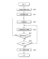
- FIG. 11 is a flowchart showing the operation of the negligence rate determination server 30.
- the negligence rate determination server 30 acquires the determination basic information (step S20).
- the judgment basic information is the information acquired regarding the accident among the information regarding each judgment item shown in FIG.
- the negligence ratio determination server 30 acquires the case information based on the acquired determination basic information (step S21).
- the negligence ratio determination server 30 performs a judgment process of the negligence ratio related to the accident by referring to the judgment basic information for the case information (step S22). Then, the determination result is transmitted to the operator terminal 40, and control is performed to display the determination screen in a predetermined format (step S23).
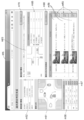
- FIG. 12 to 15 are schematic views illustrating screens displayed on the operator terminal 40.
- FIG. 12 is a schematic diagram illustrating a negligence rate determination screen.
- FIG. 13 is a schematic diagram illustrating a travel information detail screen.
- FIG. 14 is a schematic diagram illustrating a case information display screen.
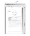
- FIG. 15 is a schematic diagram illustrating a determination report display screen.
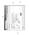
- the negligence rate determination screen M5 shown in FIG. 12 is applied to the animation rate area m51 for explaining the accident situation by animation, the basic information display area m52 for displaying the basic information of the person who caused the accident, and the negligence rate determination.
- a judgment information display column m53 in which case information (for example, an accident situation diagram (application diagram) in “Case Times (registered trademark)”) is displayed, and a judgment display column m55 in which a negligence ratio and a correction factor for the negligence ratio are displayed,
- a judgment item display field m56 in which items (judgment items) to be considered in the judgment of the negligence ratio are displayed, a judgment item detail display field m59, a print button (not shown), a case data display button m70, and a similar case.
- a display button m80 is included among them, and a correction element column in the determination information display column m53, the case detail display column m54, and the determination display column m55. Displays information extracted from the case data D31 (see FIG. 4.)
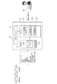
- the negligence ratio determination screen M5 shown in FIG. 12 has at least a determination item display field m56 and a determination item detail display field m59. By displaying it, the judgment of the accident situation can be grasped objectively and easily.For example, the operator operates the confirmation button m57 in the judgment item display column m56 by the user (click, etc.) The detailed display corresponding to is displayed in the detailed display field m59. Further, when the user operates (clicks, etc.) the detailed display button m60 in the detailed display field m59, objective evidence data of the determination item, For example, a moving image captured by the drive recorder is displayed.
- Each line of the correction element in the determination display field m55 can be selected by a predetermined user operation using the operation input unit 43 (eg, pointing operation using a mouse).
- the error rate adjustment value in the selected row is reflected in the error rate. For example, if the row of "Significant negligence in A" is selected when the basic fault rate is "A0: B100”, the fault rate of A is corrected to "+10”, and the fault rate becomes "A10: B10". : B90 ”.
- a confirmation button m57 and a pull-down type search condition selection button are provided in each judgment item row of the judgment item display column m56.
- the determination item detail display field m59 is automatically scrolled, and information regarding the determination item for which the confirmation button m57 is operated is displayed. If there is an item for which the confirmation button m57 has not been operated even once among the determination items displayed in the determination item display field m56 (that is, there is a determination item for which details have not been confirmed), the relevant determination item is highlighted. Then, the operator is notified of the alert.
- the fact that is the basis of the judgment of the negligence rate and the image of evidence for proving the fact are displayed in association with each other.
- the determination item detail display field m59 still images and text data related to each determination item displayed in the determination item display field m56 are displayed in a thumbnail format.
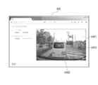
- the driving information detail screen M6 includes a moving image display area m61 in which a moving image related to the determination item is reproduced. This moving image is extracted from the video data captured by the drive recorder.
- the still image displayed in the determination item detail display field m59 is one frame in the moving image.
- a portion related to the determination result of the error rate is highlighted. For example, in FIG. 12, a tail lamp (brake lamp) of a vehicle traveling in front and a bicycle traveling on a sidewalk are highlighted by frames m62 and m63 displayed in an overlapping manner.
- a new tab or window opens and a similar case display screen (not shown) is displayed.
- a situation diagram application diagram of an accident in the case information about a case similar to the case is displayed in a thumbnail system.
- a new tab or window is opened and a case summary display screen (not shown) is displayed.
- a case summary display screen (not shown) is displayed.
- the selected application diagram, the summary of the judgment, the excerpt of the judgment, and the negligence rate determined in the judgment are displayed.
- the negligence rate determination server 30 causes the operator terminal 40 to display the screens shown in FIGS. 12 to 14 according to the signal transmitted in response to the operation on the operator terminal 40 (step S23). Further, when a user operation to correct the determination item is performed on the operator terminal 40 (step S24: Yes), the negligence ratio determination server 30 performs the negligence ratio determination process in accordance with the signal transmitted in response to the user operation. The process is executed again (step S22).
- the negligence ratio determination server 30 determines whether or not the operator terminal 40 performs an operation of determining the negligence ratio (step S25). ). For example, when the operator terminal 40 transmits a signal indicating that a predetermined user operation has been performed to the print button (not shown) in the error rate determination screen M5, the error rate determination server 30 determines the error rate. It is determined that an operation has been performed.
- step S25: Yes the negligence rate determination server 30 transmits a report screen to the operator terminal 40 to display it (step S26).
- step S25: No the error rate determination server 30 continues to display the determination screen on the operator terminal 40 (step S23).
- the judgment report display screen M10 includes a preamble display field m101, an animation display area m102 for explaining the accident situation in animation, a text display area m103 for explaining the accident situation in text, and precedent information applied to the error rate judgment.
- Information display field m104 in which the application diagram of “No.” is displayed, judgment display field m105 in which the basic error rate and correction factors are displayed, judgment result display field m106 in which the conclusion of the error rate judgment is displayed, and comment display And a column m107.
- the determination report display screen M10 is a report screen for disclosing the determination result of the negligence ratio and its basis to the insurance policyholder or the other insurance company of the accident, and can be printed.
- the accident situation is visualized and displayed based on the objective information, so that the accident situation can be grasped objectively and easily. Also, since the evidence data of the judgment item is displayed according to the user operation for the judgment item, the operator can easily grasp the accident situation. Further, according to the embodiment of the present invention, an operator can confirm efficient and objective information (for example, video data of a drive record), and a fair negligence rate can be determined. In particular, the situation of the accident is reproduced based on not only the subjective information such as the testimony of the parties and witnesses but also the video data taken by the drive recorder of the vehicles of the parties or vehicles traveling in the surroundings. It is possible to determine a very satisfactory fault rate. Further, it is possible to easily confirm the accident situation based on the objective facts in the automobile accident, and it is also possible to easily confirm the judgment result of the negligence ratio based on the accident situation and the basis thereof.
- efficient and objective information for example, video data of a drive record
- the user since the case information applied in determining the negligence rate and the facts that are the basis of the application are displayed on the same screen, the user (operator) can determine the logic of the negligence rate determination. It is easy to understand and necessary elements can be easily modified.
- the error rate determination server 30 determines the error rate and performs various display controls, and causes the operator terminal 40 to display a predetermined screen.
- the operator terminal 40 may perform control for determining the error rate and displaying a predetermined screen on the display device (display unit 42).
- the own vehicle behavior data D27 and the other vehicle / surrounding environment data D28 are used for the accident situation grasp server 20 or the error rate determination.
- These programs may be downloaded from the server 30 and executed.
- Opponent vehicle / surrounding environment grasping unit 236 ... Driving locus extraction unit 237 ... Acceleration waveform generation unit 238 ... Map Over data matching unit 239,333,461 ... the display control unit 331 ... precedents information acquisition unit 332 ; negligence determination section 334 ... unconfirmed item alert display unit 335 ... references presentation section
Landscapes
- General Physics & Mathematics (AREA)
- Physics & Mathematics (AREA)
- Business, Economics & Management (AREA)
- Engineering & Computer Science (AREA)
- Finance (AREA)
- Accounting & Taxation (AREA)
- General Business, Economics & Management (AREA)
- Economics (AREA)
- Strategic Management (AREA)
- Theoretical Computer Science (AREA)
- Marketing (AREA)
- Analytical Chemistry (AREA)
- Chemical & Material Sciences (AREA)
- Development Economics (AREA)
- Technology Law (AREA)
- Signal Processing (AREA)
- Computer Networks & Wireless Communication (AREA)
- Health & Medical Sciences (AREA)
- Tourism & Hospitality (AREA)
- Multimedia (AREA)
- Primary Health Care (AREA)
- Emergency Management (AREA)
- Environmental & Geological Engineering (AREA)
- Public Health (AREA)
- Human Resources & Organizations (AREA)
- General Health & Medical Sciences (AREA)
- Financial Or Insurance-Related Operations Such As Payment And Settlement (AREA)
- Traffic Control Systems (AREA)
- Management, Administration, Business Operations System, And Electronic Commerce (AREA)
Abstract
Description
(1)実施形態の構成
図1は、本発明の実施形態に係る事故処理システムの概略構成を示す図である。本実施形態に係る事故処理システム1は、自動車保険を販売する損害保険会社における利用を想定したものである。図1に示すように、事故処理システム1は、事故検知サーバ10と、事故状況把握サーバ20と、過失割合判定サーバ30と、オペレータ端末40と、を備える。これらの事故検知サーバ10と、事故状況把握サーバ20と、過失割合判定サーバ30と、オペレータ端末40とは、通信ネットワークNを介して接続される。なお、図1においては、オペレータ端末40を1台のみ図示しているが、複数のオペレータ端末40を設けてもよい。また、図1においては、事故検知サーバ10、事故状況把握サーバ20、過失割合判定サーバ30を1台ずつ図示しているが、これらのサーバを1台のハードウェアで構成しても良いし、各サーバを複数のハードウェアで構成しても良い。オペレータは、ユーザと称してもよい。
(a)標識情報や制限速度情報等の道路情報:民間業者が運営する道路情報システム102から取得する。
(b)ドライブレコーダにより撮影された映像データ:事故の当事者のデバイスに設置されたドライブレコーダにより撮影された映像データを取得する。映像データは、事故の当事者のデバイスから直接取得しても良いし、民間のサービス業者が運営するドライブレコーダデバイスシステム103から取得しても良い。また、事故当時に事故の発生地点周辺を走行していたデバイスに設置されたドライブレコーダにより撮影された映像データを、ドライブレコーダデバイスシステム103から取得しても良い。
(c)地図情報:民間業者が運営する地図情報システム104から取得する。
(d)天候情報:民間又は公的機関が運営する天候情報システム105から取得する。
(e)コンタクト履歴情報:事故の当事者が自社の保険の契約者である場合に、過去のコンタクト履歴を損害サービスシステム106から取得する。
操作入力部43は、キーボード、各種操作ボタン、表示部42に設けられたタッチパネル、マウス等のポインティングデバイスといった入力デバイスである。
出力部44は、プリンタ等の出力デバイスである。
図7は、事故検知サーバ10の動作を示すフローチャートである。
事故検知サーバ10は、事故が発生し、デバイスからデバイスデータが送信されると、デバイスデータを取得し(ステップS10)、取得したデバイスデータを解析することにより事故検知処理を行う(ステップS11、図1参照)。
上記実施形態においては、過失割合判定サーバ30において過失割合の判定や、種々の表示制御を行い、オペレータ端末40に所定の画面を表示させることとした。しかしながら、オペレータ端末40において、過失割合を判定したり、所定の画面を表示装置(表示部42)表示するための制御を行ったりしても良い。この場合、オペレータ端末40に、過失割合判定用のプログラム及び画面表示制御用のプログラムをインストールした上で、自車両挙動データD27及び相手車両・周辺環境データD28を事故状況把握サーバ20又は過失割合判定サーバ30からダウンロードし、これらのプログラムを実行すれば良い。
10…事故検知サーバ
11、21、31、41…通信インタフェース
12、22、32、45…記憶部
13、23、33、46…プロセッサ
20…事故状況把握サーバ
30…過失割合判定サーバ
40…オペレータ端末
42…表示部
43…操作入力部
44…出力部
101…デバイス
102…道路情報システム
103…ドライブレコーダデバイスシステム
104…地図情報システム
105…天候情報システム
106…損害サービスシステム
131…デバイス差異補正部
132…事故検知部
133…事故通報部
231…自車両運転挙動把握部
232…運転軌跡抽出部
233…加速度波形生成部
234…地図データマッチング部
235…相手車両・周辺環境把握部
236…運転軌跡抽出部
237…加速度波形生成部
238…地図データマッチング部
239、333、461…表示制御部
331…判例情報取得部
332…過失判定部
334…未確認項目アラート表示部
335…参考文献提示部
Claims (10)
- 情報処理装置に、
事故状況の判定に用いる複数のデータを受信し、
前記複数のデータに基づいて、事故状況を判定する複数の判定項目及び判定結果を表示する第1表示領域、及び前記判定結果に対する証拠データを有する判定項目において前記証拠データを表示する第2表示領域を含む判定画面を表示装置に表示制御し、
前記第1表示領域内の所定の判定結果に対するユーザの選択操作に基づく命令を受け付け、
前記命令に基づいて、前記所定の判定結果に対する証拠データを前記第2表示領域内に表示するよう表示制御する、処理を実行させるプログラム。 - 前記証拠データが、車両に搭載された撮像装置により撮像された動画像を含む場合、
前記判定項目に関連付けて前記動画像の一部の静止画像を表示するよう表示制御する、処理を前記情報処理装置にさらに実行させる、請求項1に記載のプログラム。 - 前記第2表示領域内の所定の静止画像に対するユーザ操作に基づく第2命令を受け付け、
前記第2命令に基づいて、前記所定の静止画像に対する動画像を再生する再生画面を表示するよう表示制御する、処理を前記情報処理装置にさらに実行させる、請求項2に記載のプログラム。 - 前記動画像は、前記判定項目に応じて異なる、請求項3に記載のプログラム。
- 前記動画像内で、前記判定結果に関連する箇所が強調表示される、請求項3又は4に記載のプログラム。
- 前記判定項目は、衝突時の自車両の接触箇所を示す項目を含む場合、
前記接触箇所を示す項目に対するユーザ操作に基づく第3命令を受け付け、
前記第3命令に基づいて、時計に車両を重ねて表示し、前記時計の12時方向に前記車両の前方を表示し、及び前記接触箇所を前記車両に表示するよう表示制御する、処理を前記情報処理装置にさらに実行させる、請求項1から5のいずれか一項に記載のプログラム。 - 前記判定画面に、前記複数のデータと過去の判例データとを用いて判定された基本過失割合を表示する第3表示領域、及び前記判例データの表示に関する所定のUI部品を含めて表示するよう表示制御し、
前記所定のUI部品に対するユーザ操作に基づく第4命令を受け付け、
前記第4命令に基づき、前記基本過失割合の判定に用いられた判例データを表示するよう表示制御する、処理を前記情報処理装置にさらに実行させる、請求項1から6のいずれか一項に記載のプログラム。 - 前記判定画面に、前記複数データに基づいて判定された事故状況を説明する地図データを表示する第4表示領域を含めて表示するよう表示制御する、処理を前記情報処理装置にさらに実行させる、請求項1から7のいずれか一項に記載のプログラム。
- 前記判定結果を修正するユーザ操作に基づく第5命令を受け付け、
前記第5命令に基づいて、前記判定結果の修正を反映する、処理を前記情報処理装置にさらに実行させる、請求項1から7のいずれか一項に記載のプログラム。 - 事故状況の判定に用いる複数のデータを受信し、
前記複数のデータに基づいて、事故状況を判定する複数の判定項目及び判定結果を表示する第1表示領域、及び前記判定結果に対する証拠データを有する判定項目において前記証拠データを表示する第2表示領域を含む判定画面を表示装置に表示制御し、
前記第1表示領域内の所定の判定結果に対するユーザの選択操作に基づく命令を受け付け、
前記命令に基づいて、前記所定の判定結果に対する証拠データを前記第2表示領域内に表示するように表示制御する、ことを含む情報処理方法。
Priority Applications (2)
| Application Number | Priority Date | Filing Date | Title |
|---|---|---|---|
| EP19861283.0A EP3680875A4 (en) | 2018-10-18 | 2019-07-29 | INFORMATION PROCESSING PROGRAM AND PROCESS |
| US16/635,834 US20230186396A1 (en) | 2018-10-18 | 2019-07-29 | The Program and Information Processing Method |
Applications Claiming Priority (2)
| Application Number | Priority Date | Filing Date | Title |
|---|---|---|---|
| JP2018-196997 | 2018-10-18 | ||
| JP2018196997A JP6534169B1 (ja) | 2018-10-18 | 2018-10-18 | プログラム及び情報処理方法 |
Publications (1)
| Publication Number | Publication Date |
|---|---|
| WO2020079916A1 true WO2020079916A1 (ja) | 2020-04-23 |
Family
ID=67023715
Family Applications (1)
| Application Number | Title | Priority Date | Filing Date |
|---|---|---|---|
| PCT/JP2019/029688 Ceased WO2020079916A1 (ja) | 2018-10-18 | 2019-07-29 | プログラム及び情報処理方法 |
Country Status (4)
| Country | Link |
|---|---|
| US (1) | US20230186396A1 (ja) |
| EP (1) | EP3680875A4 (ja) |
| JP (1) | JP6534169B1 (ja) |
| WO (1) | WO2020079916A1 (ja) |
Cited By (1)
| Publication number | Priority date | Publication date | Assignee | Title |
|---|---|---|---|---|
| WO2023017652A1 (ja) * | 2021-08-11 | 2023-02-16 | ソニーグループ株式会社 | 情報処理装置、情報処理方法、サーバ装置、車両装置及び情報処理プログラム |
Families Citing this family (9)
| Publication number | Priority date | Publication date | Assignee | Title |
|---|---|---|---|---|
| JP6833258B1 (ja) * | 2020-03-31 | 2021-02-24 | あいおいニッセイ同和損害保険株式会社 | 情報処理方法、情報処理装置、及びプログラム |
| JP2022123947A (ja) * | 2021-02-15 | 2022-08-25 | 株式会社デンソーテン | 事故通報装置、事故通報システム、および、事故通報方法 |
| JP7089102B1 (ja) * | 2021-10-26 | 2022-06-21 | 東京海上日動火災保険株式会社 | 事故分析装置、事故分析方法、およびプログラム |
| JP7089103B1 (ja) * | 2021-10-26 | 2022-06-21 | 東京海上日動火災保険株式会社 | 事故分析装置、事故分析方法、およびプログラム |
| JP2023131043A (ja) * | 2022-03-08 | 2023-09-21 | 東京海上日動火災保険株式会社 | 情報処理装置、情報処理方法及びプログラム |
| US12077174B2 (en) * | 2022-08-24 | 2024-09-03 | Toyota Motor Engineering & Manufacturing North America, Inc. | Compensating mismatch in abnormal driving behavior detection |
| JP2025125791A (ja) * | 2024-02-16 | 2025-08-28 | ソフトバンクグループ株式会社 | データ処理装置、データ処理方法、及びデータ処理プログラム |
| WO2026038450A1 (ja) * | 2024-08-14 | 2026-02-19 | 日本電気株式会社 | 情報処理装置、システム、方法、及び、プログラム |
| JP7795039B1 (ja) * | 2025-04-30 | 2026-01-06 | ヨンソ チョン | 訴訟及び事件の類型別データベース及び使用者から入力を受けた事実関係に基づいた創作物生成装置 |
Citations (12)
| Publication number | Priority date | Publication date | Assignee | Title |
|---|---|---|---|---|
| JPS5533626B2 (ja) | 1976-10-12 | 1980-09-01 | ||
| JP2000285377A (ja) | 1999-03-31 | 2000-10-13 | Matsushita Electric Ind Co Ltd | 緊急事態情報表示方法及び装置 |
| JP2001347972A (ja) | 2000-04-20 | 2001-12-18 | Caterpillar Inc | 履帯用オフセット対称リンク及び関連サブアセンブリ |
| JP2003067578A (ja) * | 2001-08-22 | 2003-03-07 | Aioi Insurance Co Ltd | 損害調査支援システム |
| JP2004062364A (ja) * | 2002-07-26 | 2004-02-26 | Hitachi Ltd | 事故情報処理システム |
| JP2004126808A (ja) * | 2002-09-30 | 2004-04-22 | Nissay Dowa General Insurance Co Ltd | 難易度別案件分類業務支援装置及びその方法、並びに難易度別案件分類業務支援プログラム、難易度別案件分類業務支援システム |
| US20040102985A1 (en) * | 2002-11-27 | 2004-05-27 | Stefan Wahlbin | Computerized method and system for estimating an effect on liability based on the stopping distance of vehicles |
| JP2005057343A (ja) * | 2003-08-05 | 2005-03-03 | Tokio Marine & Nichido Fire Insurance Co Ltd | 画像データ登録装置及び方法 |
| JP2009083815A (ja) * | 2007-10-03 | 2009-04-23 | Fujitsu Ten Ltd | ドライブレコーダ装置および事故解析シミュレーション装置 |
| JP2011204116A (ja) | 2010-03-26 | 2011-10-13 | Ms&Ad Research Institute Co Ltd | 保険会社システム |
| JP2017116998A (ja) * | 2015-12-21 | 2017-06-29 | セゾン自動車火災保険株式会社 | 情報処理装置、情報処理システム、情報処理方法、情報処理プログラム |
| JP2017142840A (ja) * | 2017-04-11 | 2017-08-17 | 株式会社ユピテル | 運行管理システム |
Family Cites Families (7)
| Publication number | Priority date | Publication date | Assignee | Title |
|---|---|---|---|---|
| JP2006120137A (ja) * | 2001-02-19 | 2006-05-11 | Hitachi Kokusai Electric Inc | 画像情報通報システム |
| US7895063B2 (en) * | 2002-11-27 | 2011-02-22 | Computer Sciences Corporation | Computerized method and system for creating pre-configured claim reports including liability in an accident estimated using a computer system |
| US20080008364A1 (en) * | 2006-07-10 | 2008-01-10 | Teng-Tsai Huang | Video monitoring device for vehicle |
| US10387960B2 (en) * | 2012-05-24 | 2019-08-20 | State Farm Mutual Automobile Insurance Company | System and method for real-time accident documentation and claim submission |
| KR101656808B1 (ko) * | 2015-03-20 | 2016-09-22 | 현대자동차주식회사 | 사고 정보 관리 장치, 이를 포함하는 차량 및 사고 정보 관리 방법 |
| EP3482347B1 (en) * | 2016-10-25 | 2021-02-17 | Owl Cameras, Inc. | Video-based data collection, image capture and analysis configuration |
| US10796578B1 (en) * | 2018-10-15 | 2020-10-06 | Fender2Fender, LLC | Method and system for distributing electronic accident status information over a network to a remote subscriber portable computing device during or after a vehicle accident |
-
2018
- 2018-10-18 JP JP2018196997A patent/JP6534169B1/ja active Active
-
2019
- 2019-07-29 US US16/635,834 patent/US20230186396A1/en not_active Abandoned
- 2019-07-29 EP EP19861283.0A patent/EP3680875A4/en not_active Withdrawn
- 2019-07-29 WO PCT/JP2019/029688 patent/WO2020079916A1/ja not_active Ceased
Patent Citations (12)
| Publication number | Priority date | Publication date | Assignee | Title |
|---|---|---|---|---|
| JPS5533626B2 (ja) | 1976-10-12 | 1980-09-01 | ||
| JP2000285377A (ja) | 1999-03-31 | 2000-10-13 | Matsushita Electric Ind Co Ltd | 緊急事態情報表示方法及び装置 |
| JP2001347972A (ja) | 2000-04-20 | 2001-12-18 | Caterpillar Inc | 履帯用オフセット対称リンク及び関連サブアセンブリ |
| JP2003067578A (ja) * | 2001-08-22 | 2003-03-07 | Aioi Insurance Co Ltd | 損害調査支援システム |
| JP2004062364A (ja) * | 2002-07-26 | 2004-02-26 | Hitachi Ltd | 事故情報処理システム |
| JP2004126808A (ja) * | 2002-09-30 | 2004-04-22 | Nissay Dowa General Insurance Co Ltd | 難易度別案件分類業務支援装置及びその方法、並びに難易度別案件分類業務支援プログラム、難易度別案件分類業務支援システム |
| US20040102985A1 (en) * | 2002-11-27 | 2004-05-27 | Stefan Wahlbin | Computerized method and system for estimating an effect on liability based on the stopping distance of vehicles |
| JP2005057343A (ja) * | 2003-08-05 | 2005-03-03 | Tokio Marine & Nichido Fire Insurance Co Ltd | 画像データ登録装置及び方法 |
| JP2009083815A (ja) * | 2007-10-03 | 2009-04-23 | Fujitsu Ten Ltd | ドライブレコーダ装置および事故解析シミュレーション装置 |
| JP2011204116A (ja) | 2010-03-26 | 2011-10-13 | Ms&Ad Research Institute Co Ltd | 保険会社システム |
| JP2017116998A (ja) * | 2015-12-21 | 2017-06-29 | セゾン自動車火災保険株式会社 | 情報処理装置、情報処理システム、情報処理方法、情報処理プログラム |
| JP2017142840A (ja) * | 2017-04-11 | 2017-08-17 | 株式会社ユピテル | 運行管理システム |
Non-Patent Citations (1)
| Title |
|---|
| See also references of EP3680875A4 |
Cited By (4)
| Publication number | Priority date | Publication date | Assignee | Title |
|---|---|---|---|---|
| WO2023017652A1 (ja) * | 2021-08-11 | 2023-02-16 | ソニーグループ株式会社 | 情報処理装置、情報処理方法、サーバ装置、車両装置及び情報処理プログラム |
| JPWO2023017652A1 (ja) * | 2021-08-11 | 2023-02-16 | ||
| US12499490B2 (en) | 2021-08-11 | 2025-12-16 | Sony Group Corporation | Information processing device, information processing method, server device, vehicle device, and information processing program |
| JP7816360B2 (ja) | 2021-08-11 | 2026-02-18 | ソニーグループ株式会社 | 情報処理装置、情報処理方法及び情報処理プログラム |
Also Published As
| Publication number | Publication date |
|---|---|
| US20230186396A1 (en) | 2023-06-15 |
| EP3680875A1 (en) | 2020-07-15 |
| EP3680875A4 (en) | 2021-06-23 |
| JP2020064528A (ja) | 2020-04-23 |
| JP6534169B1 (ja) | 2019-06-26 |
Similar Documents
| Publication | Publication Date | Title |
|---|---|---|
| WO2020079916A1 (ja) | プログラム及び情報処理方法 | |
| US10974728B2 (en) | Methods and systems for facilitating drive related data for driver monitoring | |
| JP7470486B2 (ja) | 事故報告を生成する方法 | |
| CA2889367C (en) | Systems, methods, and apparatus for generating customized virtual reality experiences | |
| JP6098419B2 (ja) | 交通情報案内システム、交通情報案内装置、交通情報案内方法及びコンピュータプログラム | |
| JP2023100850A (ja) | オブジェクト検出装置、オブジェクト検出方法およびプログラム | |
| JP7844710B2 (ja) | プログラム及び情報処理方法 | |
| JP2021018751A (ja) | プログラム、情報処理方法及び情報処理装置 | |
| JP6735391B2 (ja) | プログラム及び情報処理方法 | |
| JP6808886B1 (ja) | プログラム及び情報処理方法 | |
| JP6808876B2 (ja) | プログラム及び情報処理方法 | |
| CN116304986B (zh) | 车辆事件融合方法、装置、设备及可读存储介质 | |
| WO2020215976A1 (zh) | 用于处理交通事故的方法和装置 | |
| Green | 25 Driver Interface Safety and Usability Standards: An Overview | |
| Bautu et al. | In-vehicle software system for fostering driver’s attentiveness | |
| JP2022098200A (ja) | 交通事故状況分析システム、交通事故状況分析方法およびプログラム | |
| Hankey et al. | VTTI L2 naturalistic driving study: A self-funded effort to capture L2 feature use landscape | |
| Lee et al. | Does order matter? Investigating the effect of sequence on glance duration during on-road driving | |
| JP7816197B2 (ja) | 情報処理装置、情報処理方法、及び、プログラム | |
| JP7749881B1 (ja) | 情報処理装置および情報処理方法 | |
| US12482048B1 (en) | System and method for coordinating communication and data collection | |
| Shirani et al. | Evaluating Older Drivers’ Reaction to Forward Collision Warning (FCW) and Automated Emergency Braking (AEB) Under Conditions of Distraction Using a Driving Simulation | |
| Crowson | Now You See Me: Investigating the Impact of Automated Visual Search Aids on the Rate of Subsequent Search Misses Within a Driving Context | |
| JP2021056645A (ja) | 情報処理装置、情報処理方法及びプログラム | |
| Bazaraa et al. | AI-Powered Driver Fatigue and Distraction Detection Cameras |
Legal Events
| Date | Code | Title | Description |
|---|---|---|---|
| ENP | Entry into the national phase |
Ref document number: 2019861283 Country of ref document: EP Effective date: 20200408 |
|
| ENP | Entry into the national phase |
Ref document number: 2019341064 Country of ref document: AU Date of ref document: 20190729 Kind code of ref document: A |
|
| 121 | Ep: the epo has been informed by wipo that ep was designated in this application |
Ref document number: 19861283 Country of ref document: EP Kind code of ref document: A1 |
|
| NENP | Non-entry into the national phase |
Ref country code: DE |