WO2020080481A1 - コイルの装着構造 - Google Patents
コイルの装着構造 Download PDFInfo
- Publication number
- WO2020080481A1 WO2020080481A1 PCT/JP2019/040950 JP2019040950W WO2020080481A1 WO 2020080481 A1 WO2020080481 A1 WO 2020080481A1 JP 2019040950 W JP2019040950 W JP 2019040950W WO 2020080481 A1 WO2020080481 A1 WO 2020080481A1
- Authority
- WO
- WIPO (PCT)
- Prior art keywords
- coil
- motor rotation
- motor
- circumferential direction
- turns
- Prior art date
- Legal status (The legal status is an assumption and is not a legal conclusion. Google has not performed a legal analysis and makes no representation as to the accuracy of the status listed.)
- Ceased
Links
Images

Classifications
-
- H—ELECTRICITY
- H02—GENERATION; CONVERSION OR DISTRIBUTION OF ELECTRIC POWER
- H02K—DYNAMO-ELECTRIC MACHINES
- H02K3/00—Details of windings
- H02K3/04—Windings characterised by the conductor shape, form or construction, e.g. with bar conductors
- H02K3/18—Windings for salient poles
-
- H—ELECTRICITY
- H02—GENERATION; CONVERSION OR DISTRIBUTION OF ELECTRIC POWER
- H02K—DYNAMO-ELECTRIC MACHINES
- H02K3/00—Details of windings
- H02K3/04—Windings characterised by the conductor shape, form or construction, e.g. with bar conductors
- H02K3/28—Layout of windings or of connections between windings
-
- H—ELECTRICITY
- H01—ELECTRIC ELEMENTS
- H01F—MAGNETS; INDUCTANCES; TRANSFORMERS; SELECTION OF MATERIALS FOR THEIR MAGNETIC PROPERTIES
- H01F5/00—Coils
-
- H—ELECTRICITY
- H02—GENERATION; CONVERSION OR DISTRIBUTION OF ELECTRIC POWER
- H02K—DYNAMO-ELECTRIC MACHINES
- H02K1/00—Details of the magnetic circuit
- H02K1/06—Details of the magnetic circuit characterised by the shape, form or construction
- H02K1/12—Stationary parts of the magnetic circuit
- H02K1/16—Stator cores with slots for windings
- H02K1/165—Shape, form or location of the slots
-
- H—ELECTRICITY
- H02—GENERATION; CONVERSION OR DISTRIBUTION OF ELECTRIC POWER
- H02K—DYNAMO-ELECTRIC MACHINES
- H02K1/00—Details of the magnetic circuit
- H02K1/06—Details of the magnetic circuit characterised by the shape, form or construction
- H02K1/22—Rotating parts of the magnetic circuit
- H02K1/32—Rotating parts of the magnetic circuit with channels or ducts for flow of cooling medium
-
- H—ELECTRICITY
- H02—GENERATION; CONVERSION OR DISTRIBUTION OF ELECTRIC POWER
- H02K—DYNAMO-ELECTRIC MACHINES
- H02K3/00—Details of windings
- H02K3/04—Windings characterised by the conductor shape, form or construction, e.g. with bar conductors
- H02K3/12—Windings characterised by the conductor shape, form or construction, e.g. with bar conductors arranged in slots
-
- H—ELECTRICITY
- H02—GENERATION; CONVERSION OR DISTRIBUTION OF ELECTRIC POWER
- H02K—DYNAMO-ELECTRIC MACHINES
- H02K3/00—Details of windings
- H02K3/46—Fastening of windings on the stator or rotor structure
- H02K3/48—Fastening of windings on the stator or rotor structure in slots
-
- H—ELECTRICITY
- H02—GENERATION; CONVERSION OR DISTRIBUTION OF ELECTRIC POWER
- H02K—DYNAMO-ELECTRIC MACHINES
- H02K1/00—Details of the magnetic circuit
- H02K1/06—Details of the magnetic circuit characterised by the shape, form or construction
- H02K1/12—Stationary parts of the magnetic circuit
- H02K1/14—Stator cores with salient poles
- H02K1/146—Stator cores with salient poles consisting of a generally annular yoke with salient poles
- H02K1/148—Sectional cores
-
- H—ELECTRICITY
- H02—GENERATION; CONVERSION OR DISTRIBUTION OF ELECTRIC POWER
- H02K—DYNAMO-ELECTRIC MACHINES
- H02K2203/00—Specific aspects not provided for in the other groups of this subclass relating to the windings
- H02K2203/09—Machines characterised by wiring elements other than wires, e.g. bus rings, for connecting the winding terminations
-
- H—ELECTRICITY
- H02—GENERATION; CONVERSION OR DISTRIBUTION OF ELECTRIC POWER
- H02K—DYNAMO-ELECTRIC MACHINES
- H02K2213/00—Specific aspects, not otherwise provided for and not covered by codes H02K2201/00 - H02K2211/00
- H02K2213/03—Machines characterised by numerical values, ranges, mathematical expressions or similar information
-
- H—ELECTRICITY
- H02—GENERATION; CONVERSION OR DISTRIBUTION OF ELECTRIC POWER
- H02K—DYNAMO-ELECTRIC MACHINES
- H02K3/00—Details of windings
- H02K3/46—Fastening of windings on the stator or rotor structure
- H02K3/52—Fastening salient pole windings or connections thereto
- H02K3/521—Fastening salient pole windings or connections thereto applicable to stators only
- H02K3/522—Fastening salient pole windings or connections thereto applicable to stators only for generally annular cores with salient poles
Definitions
- the present invention relates to a winding shaft having a shape in which a columnar tooth portion projectingly provided on an inner peripheral surface of an annular yoke portion of a stator of a motor and a plate-shaped conductive wire extending in a band shape are bent in the width direction and wound.
- the present invention relates to a coil mounting structure having first to n-th turns (n is an integer of 2 or more) stacked in the direction, and a coil mounted on the teeth portion.
- Patent Document 1 discloses a coil having first to n-th turns (n is an integer of 2 or more) laminated in the winding axis direction in a shape in which a plate-shaped conductor wire extending in a band shape is bent in the width direction and wound. It is disclosed. The conducting wire forming each turn of this coil is formed substantially flat.
- the yoke portion in order to make the thickness of the entire yoke portion in the radial direction of the motor equal to or greater than the minimum necessary thickness for preventing magnetic saturation, the yoke portion should be It is necessary to set the thickness in the radial direction of the motor to be larger than the required minimum thickness, and it is not possible to reduce the size of the motor.
- the present invention has been made in view of the above points, and an object of the present invention is to realize downsizing of a motor.
- a coil mounting structure includes a columnar tooth portion protruding from an inner peripheral surface of an annular yoke portion of a motor stator, and a plate-like extending plate-like member. And a coil attached to the teeth portion, which has first to n-th turns (n is an integer of 2 or more) stacked in the winding axis direction in a shape in which the conductor wire is bent in the width direction and wound.
- the protruding direction of the tooth portion as the tooth portion protruding portion is separated from the tooth portion protruding portion in the motor rotation circumferential direction. Is formed so as to incline or curve toward the direction.
- the conductor wire extending in the motor rotation circumferential direction on both sides of the teeth portion in the motor rotation axis direction in the first to nth turns of the coil has a thickness direction of the conductor wire.
- the bent portion is formed so as to overlap in the winding axis direction over the entire width direction of the conducting wire, and the conducting wire on both sides in the motor circumferential direction of the bending portion in the first to n-th turns of the coil is the folded wire. It is characterized in that it is inclined so as to be directed in the protruding direction of the teeth portion as it is separated from the curved portion in the motor rotation circumferential direction.
- the adjoining area is perpendicular to the protruding direction of the tooth portion.
- the thickness of the yoke in the radial direction of the motor is closer to the minimum thickness required to prevent magnetic saturation at the end of the adjacent area where the teeth protrude. Can be set to. Therefore, the present disclosure can realize miniaturization of a motor.
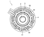
- FIG. 1A is a plan view of a motor to which a coil mounting structure according to an embodiment is applied.
- FIG. 1B is a side view of a motor to which the coil mounting structure according to the embodiment is applied.
- FIG. 1C is a sectional view taken along the line IC-IC in FIG. 1B.
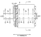
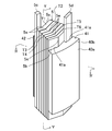
- FIG. 2 is a perspective view showing a state in which the coil is attached to the split core.
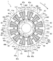
- FIG. 3 is a plan view of FIG.
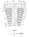
- FIG. 4 is a sectional view taken along line IV-IV in FIG.
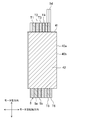
- FIG. 5 is a sectional view taken along line VV of FIG.
- the motor 1 includes a shaft 2, a rotor 3, a stator 4, coils U11 to W41, and bus bars 51 to 54 inside a cover case (not shown).
- the direction perpendicular to the paper surface is the motor rotation axis direction.
- integral or “integrated” means not only that multiple parts are mechanically connected by bolting, caulking, etc., but also by material bonding such as covalent bonding, ionic bonding, and metal bonding.
- material bonding such as covalent bonding, ionic bonding, and metal bonding.
- the shaft 2 has a hollow portion 2a inside which extends in the motor rotation axis direction, and a plurality of through holes 2b are provided on the side surface.
- the hollow portion 2a is a passage of the coolant C for cooling the inside of the motor 1, and the coolant C flows in the hollow portion 2a along the motor rotation axis direction (longitudinal direction of the shaft 2). It circulates and flows.
- a part of the refrigerant C flowing through the hollow portion 2a flows out from the plurality of through holes 2b, and also flows from the center side of the motor 1 to the outside, that is, in the direction from the rotor 3 to the stator 4, and thus the rotor 3 and the stator 4. To cool.
- the rotor 3 is provided in contact with the outer circumference of the shaft 2, and includes magnets 31, 31 ... Which face the stator 4 and whose N poles and S poles are alternately arranged along the outer circumferential direction of the shaft 2. .
- the neodymium magnet is used as the magnet 31 used in the rotor 3, but the material, shape and material of the magnet 31 may be appropriately changed according to the output of the motor 1.
- the stator 4 includes a stator core 40 composed of twelve (plural) split cores 40a shown in FIGS.
- the split core 40a includes a plate-shaped split yoke portion 40b that is curved in an arc shape around the motor rotation axis.
- a tooth portion 42 is provided on the inner peripheral surface of each split yoke portion 40 b so as to project toward the center of rotation of the motor 1 over the entire motor rotation axis direction.
- the motor rotation circumferential direction is referred to as the motor rotation circumferential direction.
- the part of the tooth part 42 excluding the tip part has a columnar shape with a rectangular cross section and extends, while the tip part of the tooth part 42 projects to both sides in the motor rotation circumferential direction.
- a portion of the tooth portion 42 excluding the tip end portion has a pair of surfaces constituting the outer peripheral surface thereof oriented in the motor rotation axis direction, and the other pair of surfaces oriented in the motor rotation circumferential direction.
- the split cores 40a are connected to each other by fitting a ring-shaped holding member 44 on the outer peripheral side of the split yoke portion 40b.
- the split yoke portions 40b of the split cores 40a form a substantially annular yoke portion 41.
- the tooth portions 42 are arranged at equal intervals on the inner peripheral surface of the yoke portion 41.
- the outer peripheral surface of the yoke portion 41 is curved so as to form a circular shape in a plan view, while the area of the inner peripheral surface of the yoke portion 41 excluding the protruding portions of the teeth portions 42 is the outer peripheral surface of the yoke portion 41 in a plan view. Is curved to form a concentric circle. Therefore, in the adjoining regions of the inner peripheral surface of the yoke portion 41, which are adjacent to the protruding portions of the teeth portion 42 on both sides in the motor rotation circumferential direction, the teeth portions 42 project from the protruding portions of the teeth portion 42 in the motor rotation circumferential direction.
- a slope 41a is formed so as to curve in the direction. Slots 43, 43 ... Are provided between the tooth portions 42, 42.
- the stator 4 is arranged outside the rotor 3 with a certain distance from the rotor 3 when viewed from the direction of the motor rotation axis.
- the teeth portion 42 of the stator core 40 is configured by a laminated body formed by laminating a plurality of core sheets made of an electromagnetic steel sheet containing silicon or the like in the motor rotation axis direction (direction orthogonal to the extending direction of the teeth portion 42). There is.
- the number of magnetic poles of the rotor 3 is 10 in total including 5 N poles and 5 S poles facing the stator 4, and the number of slots 43 is 12.
- the present invention is not limited to this, and can be applied to other combinations of the number of magnetic poles and the number of slots.
- the stator 4 has twelve coils U11 to W41, and these coils U11 to W41 are attached to the teeth portions 42, 42 ...
- the motor rotation is performed. Seen from the axial direction, they are arranged in the respective slots 43, 43 ... That is, the coils U11 to W41 are concentratedly wound around the tooth portions 42, 42 ... Further, the coils U11 to U41 are integrated with the bus bar 51, the coils V12 to V42 are integrated with the bus bar 52, and the coils W11 to W41 are integrated with the bus bar 53, respectively.
- the first character represents each phase of the motor 1 (in the present embodiment, the U phase, V phase, W phase), and the second character is the same phase.
- the third character represents the winding direction of the coil, and in this embodiment, 1 is the clockwise direction and 2 is the counterclockwise direction.
- the coil U11 represents that the U-phase is the first coil in the arrangement order and the winding direction is the clockwise direction
- the coil V42 is the fourth coil in the V-phase arrangement order and the winding direction.
- the clockwise direction means a clockwise direction when viewed from the center of the motor 1
- the "counterclockwise direction” means a counterclockwise direction when viewed from the center of the motor 1.
- the coils U11 and U41 are U-phase coils, and the coils U22 and U32 are U-bar phase coils (the direction of the magnetic field generated is opposite to that of the U-phase coil), but in the following description, Unless otherwise specified, they are collectively referred to as U-phase coils.
- the coils V12 to V42 and the coils W11 to W41 are collectively referred to as a V-phase coil and a W-phase coil, respectively.
- the coils U11 to W41 are referred to as the coil 5, respectively.
- the coil 5 includes a wound conductive wire 5a, an insulating film 5b provided on the surface of the conductive wire 5a, a lead-out portion 5c drawn from a first turn T1 (described later) of the conductive wire 5a, and a sixth turn T6 (described later). And a pull-out portion 5d pulled out from.
- the conducting wire 5a is formed by bending a plate-shaped conducting wire having a quadrangular cross section and extending in a strip shape in the width direction and winding it in a single layer for 6 turns, and is laminated in the winding axis direction from the first to sixth turns T1 to T6. It consists of a turn sequence.
- the portion wound from the tip of the pull-out portion 5c to below the position where the pull-out portion 5d is provided is referred to as a first turn T1, and the subsequent portions wound one turn at a time are sequentially arranged in the second to sixth turns T2.
- Count as ⁇ T6. Further, how to obtain the starting point of each of the turns T1 to T6 can be arbitrarily determined.
- first to sixth turns T1 to T6 are gradually thickened in the protruding direction of the teeth portion 42.
- the conducting wire 5a extending in the motor rotation circumferential direction on both sides of the teeth portion 42 in the motor rotation axis direction is rotated in the clockwise direction in FIG. 1C (the direction indicated by the arrow X in FIGS. )
- a bent portion 5e that bends in the thickness direction of the conducting wire 5a is formed near the side end portion (corner portion) so as to overlap in the winding axis direction over the entire width direction of the conducting wire 5a.
- the conducting wires 5a on both sides of the motor 5e in the circumferential direction of the motor are inclined so as to extend in the protruding direction of the teeth portion 42 as they are separated from the bent portion 5e in the circumferential direction of the motor rotation.
- An angle ⁇ formed by the conductors 5a on both sides of the bent portion 5e in the motor circumferential direction with respect to the protruding direction of the tooth portion 42 is set to an acute angle. Therefore, the conductors 5a on both sides of the bent portion 5e in the motor circumferential direction are along the inclined surface portion 41a of the yoke portion 41.
- the conducting wire 5a is made of, for example, copper, aluminum, zinc, magnesium, brass, iron, SUS or the like.
- the conductive wire 5a can be manufactured, for example, by punching the conductive wire 5a from a sheet metal every half turn and joining them by welding or the like.
- the insulating film 5b is provided on the entire surface of the conducting wire 5a except for the lead-out portions 5c and 5d so as to insulate the coil 5 from an external member (not shown).
- the coil 5 and the stator core 40 are insulated from each other by the insulating film 5b and an insulating member (not shown) such as resin or insulating paper.
- the adjacent turns of the coil 5 are insulated by the insulating film 5b.
- the insulating film 5b is made of, for example, polyimide, nylon, PEEK, acrylic, amide imide, ester imide, enamel, heat resistant resin, or the like.
- the thickness of the insulating film 5b is about several tens of ⁇ m, for example, 10 ⁇ m to 50 ⁇ m.
- the lead-out portions 5c and 5d are both a part of the conducting wire 5a, and in order to receive a current supply from the outside or to supply a current to the outside, a side surface of the coil 5, in other words, a turn string of the conducting wire 5a. It extends outward from the intersecting planes. Further, the insulating film 5b is removed from the lead-out portions 5c and 5d in order to connect with external members, for example, any of the bus bars 51 to 54 shown in FIGS. 1A and 1B. The insulating film 5b does not have to be removed in the entire area of the lead-out portions 5c and 5d, and for example, the insulating film 5b may be removed only in the portions necessary for connection with the bus bars 51 to 54.
- the inclined surface portion 41a is provided in the adjacent portion that is adjacent to the tooth portion 42 on the inner peripheral surface of the yoke portion 41 from both sides in the motor rotation circumferential direction, the adjacent portion is formed in the tooth portion 42.
- the thickness of the yoke portion 41 in the motor radial direction at the end portion on the protruding portion side of the teeth portion 42 in the adjacent region is set to prevent magnetic saturation. It can be set to a value close to the minimum required thickness. Therefore, miniaturization of the motor 1 can be realized.
- the conductors 5a on both sides in the motor circumferential direction of the bent portion 5e in the first to sixth turns T1 to T6 of the coil 5 are directed toward the protruding direction of the teeth portion 42 as the conductor 5a is separated from the bent portion 5e in the motor rotation circumferential direction. Since the coils 5 are inclined, the coil 5 is configured such that the plate surface of the conductor 5a of each of the turns T1 to T6 is perpendicular to the protruding direction of the teeth portion 42 without increasing the outer dimension of the coil 5 in the motor rotation circumferential direction.
- the area of the plate surface of the conducting wire 5a in each of the turns T1 to T6 can be increased as compared with the case where 5 is provided.
- the conductors 5a on both sides in the motor circumferential direction of the bent portion 5e in the first to sixth turns T1 to T6 of the coil 5 are directed toward the protruding direction of the teeth portion 42 as the conductor 5a is separated from the bent portion 5e in the motor rotation circumferential direction. Since the coils 5 are arranged so as to be inclined so that the plate surface of the conducting wire 5a of each of the turns T1 to T6 is perpendicular to the protruding direction of the teeth portion 42, the inner peripheral surface of the yoke portion 41 The dead space formed with the coil 5 can be narrowed. Therefore, the heat dissipation efficiency of the coil 5 can be improved, the space factor of the coil 5 in the stator 4 can be improved, and the efficiency of the motor 1 can be increased.
- the diameter of the motor 1 can be reduced by reducing the coil 5 and the tooth portion 42 in the protruding direction of the tooth portion 42. Can be miniaturized in any direction.
- the inclined surface portion 41a of the yoke portion 41 is a curved surface that curves toward the protruding direction of the tooth portion 42 as it is separated from the protruding portion of the tooth portion 42 in the motor rotation circumferential direction.
- a flat surface which is not curved and is inclined may be used.
- the angle ⁇ formed by the inclined surface portion 41a with respect to the protruding direction of the tooth portion 42 is set to an acute angle.
- the number of turns (n) of the coil 5 is set to 6, but if the number of turns is 2 or more, the number of turns (integer) other than 6 may be used.
- the conducting wire 5a of the coil 5 is formed of a wire material having a quadrangular cross section, but it may be formed of a wire material having a trapezoidal or rhombic cross section.
- the coil mounting structure according to the present disclosure can realize downsizing of a motor and is useful when applied to a motor, a power device, and the like.
Landscapes
- Engineering & Computer Science (AREA)
- Power Engineering (AREA)
- Iron Core Of Rotating Electric Machines (AREA)
- Insulation, Fastening Of Motor, Generator Windings (AREA)
- Windings For Motors And Generators (AREA)
Abstract
Description
4 ステータ
41 ヨーク部
41a 斜面部
42 ティース部
5 コイル
5a 導線
5e 折曲部
T1~T6 ターン
Claims (2)
- モータのステータの環状のヨーク部の内周面に突設された柱状のティース部と、
帯状に延びる板状の導線を幅方向に屈曲させて巻回させた形状で巻回軸方向に積層した第1~第nターン(nは2以上の整数)を有し、前記ティース部に装着されたコイルとを備え、
前記ヨーク部の内周面における前記ティース部突設箇所にモータ回転周方向両側から隣接する隣接領域には、該ティース部突設箇所からモータ回転周方向に離れるに従って前記ティース部の突出方向に向かうように傾斜又は湾曲する斜面部が形成され、
前記コイルの第1~第nターンにおける前記ティース部のモータ回転軸方向両側でモータ回転周方向に延びる導線には、該導線の厚さ方向に折れ曲がる折曲部が導線の幅方向全体に亘って巻回軸方向に重なるように形成され、前記コイルの第1~第nターンにおける前記折曲部のモータ周方向両側の導線は、前記折曲部からモータ回転周方向に離れるに従って前記ティース部の突出方向に向かうように傾斜していることを特徴とするコイルの装着構造。 - 請求項1に記載のコイルの装着構造において、
前記コイルの第1~第nターンは、前記ティース部の突出方向に向かって徐々に厚くなっていることを特徴とするコイルの装着構造。
Priority Applications (4)
| Application Number | Priority Date | Filing Date | Title |
|---|---|---|---|
| JP2020553304A JPWO2020080481A1 (ja) | 2018-10-18 | 2019-10-17 | コイルの装着構造 |
| EP19872536.8A EP3869672A4 (en) | 2018-10-18 | 2019-10-17 | Coil mounting structure |
| CN201980068021.8A CN112868164A (zh) | 2018-10-18 | 2019-10-17 | 线圈的安装构造 |
| US17/285,458 US11929654B2 (en) | 2018-10-18 | 2019-10-17 | Coil mounting structure |
Applications Claiming Priority (2)
| Application Number | Priority Date | Filing Date | Title |
|---|---|---|---|
| JP2018-196586 | 2018-10-18 | ||
| JP2018196586 | 2018-10-18 |
Publications (1)
| Publication Number | Publication Date |
|---|---|
| WO2020080481A1 true WO2020080481A1 (ja) | 2020-04-23 |
Family
ID=70283029
Family Applications (1)
| Application Number | Title | Priority Date | Filing Date |
|---|---|---|---|
| PCT/JP2019/040950 Ceased WO2020080481A1 (ja) | 2018-10-18 | 2019-10-17 | コイルの装着構造 |
Country Status (5)
| Country | Link |
|---|---|
| US (1) | US11929654B2 (ja) |
| EP (1) | EP3869672A4 (ja) |
| JP (1) | JPWO2020080481A1 (ja) |
| CN (1) | CN112868164A (ja) |
| WO (1) | WO2020080481A1 (ja) |
Cited By (2)
| Publication number | Priority date | Publication date | Assignee | Title |
|---|---|---|---|---|
| EP4203244A4 (en) * | 2020-08-27 | 2024-05-22 | IHI Corporation | STATOR |
| JP2024089918A (ja) * | 2022-12-22 | 2024-07-04 | 富田電機股▲ふん▼有限公司 | モータコイルおよびモータ固定子 |
Families Citing this family (2)
| Publication number | Priority date | Publication date | Assignee | Title |
|---|---|---|---|---|
| WO2020080479A1 (ja) * | 2018-10-18 | 2020-04-23 | パナソニックIpマネジメント株式会社 | コイル装置 |
| JP6893274B1 (ja) * | 2020-07-03 | 2021-06-23 | Dmg森精機株式会社 | モータ |
Citations (6)
| Publication number | Priority date | Publication date | Assignee | Title |
|---|---|---|---|---|
| JPS5379201A (en) * | 1976-12-23 | 1978-07-13 | Toshiba Corp | Manufacturing for interpole windings |
| JP2004261000A (ja) * | 2004-06-21 | 2004-09-16 | Hitachi Ltd | 回転電機の固定子 |
| JP2005186092A (ja) * | 2003-12-25 | 2005-07-14 | Sumitomo Electric Ind Ltd | 異形断面コイルの製造方法および異形断面コイルの組込方法 |
| JP2006014530A (ja) * | 2004-06-28 | 2006-01-12 | Sumitomo Electric Ind Ltd | コイルとその製造方法 |
| DE102012212637A1 (de) | 2012-07-18 | 2014-01-23 | Fraunhofer-Gesellschaft zur Förderung der angewandten Forschung e.V. | Gießtechnisch hergestellte elektrische Spule |
| JP2015042113A (ja) * | 2013-08-23 | 2015-03-02 | 三菱電機株式会社 | 固定子および電動機 |
Family Cites Families (10)
| Publication number | Priority date | Publication date | Assignee | Title |
|---|---|---|---|---|
| CN102655363B (zh) * | 2011-03-02 | 2014-11-26 | 株式会社丰田自动织机 | 旋转电机 |
| JP2013135587A (ja) * | 2011-12-27 | 2013-07-08 | Daikin Ind Ltd | ステータ、モータ、圧縮機およびコイル巻回方法 |
| US9502931B2 (en) * | 2012-03-23 | 2016-11-22 | Asmo Co., Ltd. | Brushless motor |
| DE102012222318A1 (de) | 2012-12-05 | 2014-06-05 | Robert Bosch Gmbh | Zahnsegment-Spulen-Kombination für eine elektrische Maschine |
| JP6196804B2 (ja) * | 2013-05-16 | 2017-09-13 | 株式会社Subaru | 回転電機のステータ |
| US9966824B2 (en) | 2013-12-25 | 2018-05-08 | Mitsubishi Electric Corporation | Magnetic inductor electric motor and manufacturing method therefor |
| JP2016067100A (ja) * | 2014-09-24 | 2016-04-28 | ダイキン工業株式会社 | モータ、圧縮機、及びモータの製造方法 |
| JP6578516B2 (ja) * | 2014-09-26 | 2019-09-25 | パナソニックIpマネジメント株式会社 | 誘導電動機 |
| JP2016082683A (ja) * | 2014-10-15 | 2016-05-16 | トヨタ自動車株式会社 | 回転電機用ステータ |
| US10320258B2 (en) * | 2015-09-28 | 2019-06-11 | Nidec Corporation | Stator, motor, disk drive apparatus, and method of manufacturing stator |
-
2019
- 2019-10-17 JP JP2020553304A patent/JPWO2020080481A1/ja active Pending
- 2019-10-17 EP EP19872536.8A patent/EP3869672A4/en not_active Withdrawn
- 2019-10-17 CN CN201980068021.8A patent/CN112868164A/zh not_active Withdrawn
- 2019-10-17 WO PCT/JP2019/040950 patent/WO2020080481A1/ja not_active Ceased
- 2019-10-17 US US17/285,458 patent/US11929654B2/en active Active
Patent Citations (6)
| Publication number | Priority date | Publication date | Assignee | Title |
|---|---|---|---|---|
| JPS5379201A (en) * | 1976-12-23 | 1978-07-13 | Toshiba Corp | Manufacturing for interpole windings |
| JP2005186092A (ja) * | 2003-12-25 | 2005-07-14 | Sumitomo Electric Ind Ltd | 異形断面コイルの製造方法および異形断面コイルの組込方法 |
| JP2004261000A (ja) * | 2004-06-21 | 2004-09-16 | Hitachi Ltd | 回転電機の固定子 |
| JP2006014530A (ja) * | 2004-06-28 | 2006-01-12 | Sumitomo Electric Ind Ltd | コイルとその製造方法 |
| DE102012212637A1 (de) | 2012-07-18 | 2014-01-23 | Fraunhofer-Gesellschaft zur Förderung der angewandten Forschung e.V. | Gießtechnisch hergestellte elektrische Spule |
| JP2015042113A (ja) * | 2013-08-23 | 2015-03-02 | 三菱電機株式会社 | 固定子および電動機 |
Non-Patent Citations (1)
| Title |
|---|
| See also references of EP3869672A4 |
Cited By (3)
| Publication number | Priority date | Publication date | Assignee | Title |
|---|---|---|---|---|
| EP4203244A4 (en) * | 2020-08-27 | 2024-05-22 | IHI Corporation | STATOR |
| US12609570B2 (en) | 2020-08-27 | 2026-04-21 | Ihi Corporation | Stator with flat angle coils with varying width and teeth having widened portions |
| JP2024089918A (ja) * | 2022-12-22 | 2024-07-04 | 富田電機股▲ふん▼有限公司 | モータコイルおよびモータ固定子 |
Also Published As
| Publication number | Publication date |
|---|---|
| EP3869672A4 (en) | 2021-12-08 |
| US20210344246A1 (en) | 2021-11-04 |
| CN112868164A (zh) | 2021-05-28 |
| JPWO2020080481A1 (ja) | 2021-09-09 |
| EP3869672A1 (en) | 2021-08-25 |
| US11929654B2 (en) | 2024-03-12 |
Similar Documents
| Publication | Publication Date | Title |
|---|---|---|
| CN111971763B (zh) | 线圈以及使用该线圈的电动机 | |
| WO2020080481A1 (ja) | コイルの装着構造 | |
| JP6432016B2 (ja) | 回転電気機械 | |
| WO2020026792A1 (ja) | モータ | |
| EP3611826B1 (en) | Coil and motor using same | |
| JP7050234B2 (ja) | モータ | |
| JP7445926B2 (ja) | コイル装置 | |
| JP7386399B2 (ja) | コイルの装着構造、ステータ及びモータ | |
| JP7535686B2 (ja) | モータ | |
| JPWO2021095343A5 (ja) | ||
| JP7066539B2 (ja) | 回転電機 | |
| WO2022259453A1 (ja) | 電動機、送風機および空気調和装置 |
Legal Events
| Date | Code | Title | Description |
|---|---|---|---|
| 121 | Ep: the epo has been informed by wipo that ep was designated in this application |
Ref document number: 19872536 Country of ref document: EP Kind code of ref document: A1 |
|
| ENP | Entry into the national phase |
Ref document number: 2020553304 Country of ref document: JP Kind code of ref document: A |
|
| NENP | Non-entry into the national phase |
Ref country code: DE |
|
| ENP | Entry into the national phase |
Ref document number: 2019872536 Country of ref document: EP Effective date: 20210518 |
|
| WWW | Wipo information: withdrawn in national office |
Ref document number: 2019872536 Country of ref document: EP |