WO2020084829A1 - Électroaimant, commutateur électromagnétique et procédé de fabrication d'électroaimant - Google Patents
Électroaimant, commutateur électromagnétique et procédé de fabrication d'électroaimant Download PDFInfo
- Publication number
- WO2020084829A1 WO2020084829A1 PCT/JP2019/024024 JP2019024024W WO2020084829A1 WO 2020084829 A1 WO2020084829 A1 WO 2020084829A1 JP 2019024024 W JP2019024024 W JP 2019024024W WO 2020084829 A1 WO2020084829 A1 WO 2020084829A1
- Authority
- WO
- WIPO (PCT)
- Prior art keywords
- iron core
- spacer
- electromagnet
- fixed
- welding
- Prior art date
- Legal status (The legal status is an assumption and is not a legal conclusion. Google has not performed a legal analysis and makes no representation as to the accuracy of the status listed.)
- Ceased
Links
Images


Classifications
-
- H—ELECTRICITY
- H01—ELECTRIC ELEMENTS
- H01F—MAGNETS; INDUCTANCES; TRANSFORMERS; SELECTION OF MATERIALS FOR THEIR MAGNETIC PROPERTIES
- H01F7/00—Magnets
- H01F7/06—Electromagnets; Actuators including electromagnets
- H01F7/08—Electromagnets; Actuators including electromagnets with armatures
-
- H—ELECTRICITY
- H01—ELECTRIC ELEMENTS
- H01F—MAGNETS; INDUCTANCES; TRANSFORMERS; SELECTION OF MATERIALS FOR THEIR MAGNETIC PROPERTIES
- H01F7/00—Magnets
- H01F7/06—Electromagnets; Actuators including electromagnets
- H01F7/08—Electromagnets; Actuators including electromagnets with armatures
- H01F7/16—Rectilinearly-movable armatures
-
- H—ELECTRICITY
- H01—ELECTRIC ELEMENTS
- H01H—ELECTRIC SWITCHES; RELAYS; SELECTORS; EMERGENCY PROTECTIVE DEVICES
- H01H50/00—Details of electromagnetic relays
- H01H50/16—Magnetic circuit arrangements
Definitions
- the present application relates to an electromagnet, an electromagnetic switch, and a method for manufacturing an electromagnet.
- the present application discloses a technique for solving the above problems, and an object thereof is to provide an electromagnet, an electromagnetic switch, and a method for manufacturing an electromagnet that have high productivity and can be produced at low cost. To do.
- the electromagnet disclosed in the present application is With a movable iron core, A fixed iron core arranged to face the movable iron core, An electromagnet having a drive coil wound around the fixed iron core, One of the movable iron core or the fixed iron core, On the surface facing the other iron core, a spacer made by processing a thin plate which is a single plate of austenitic stainless steel and is a JIS standard 2B material or a JIS standard 2D material, The spacer and the iron core are provided on at least one of the spacer and the iron core, and are welded and fixed to each other by a welding portion having a convex shape with respect to the other.
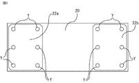
- a non-magnetic thin plate-shaped spacer or iron core for preventing magnetism remaining in the fixed iron core and the movable iron core after the energization of the electromagnet is stopped. Since a plurality of protrusions are provided on at least one side and a current can be passed through the protrusions to weld the spacer and the iron core at a time, it is expected that the time for joining the iron core and the spacer will be significantly shortened and the productivity is high.
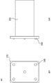
- FIG. 9 is a two-sided view showing a modified example of the movable core according to the second embodiment.
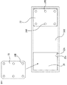
- FIG. 9 is a diagram showing an arrangement example of another protrusion according to the second embodiment. It is a figure which shows the point which positions a movable iron core and a spacer before welding using the positioning jig by Embodiment 5.
- FIG. 16 is a flowchart showing a process of welding a spacer and a movable iron core according to the fifth embodiment. It is a figure which shows the dimensional relationship of the positioning jig and spacer by Embodiment 5, and is a figure which shows the state after positioning completion and before welding.
- FIG. 19 is a diagram showing a state in which energization for welding according to the fifth embodiment is finished and welding is completed, but the electrodes are still applying pressure. It is a figure which shows the other example of the positioning jig by Embodiment 5.
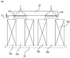
- the magnetic flux generated upward in the left fixed iron core 30a passes through the spacer 22a installed on the left side of the movable iron core 20 and reaches the movable iron core 20, and the magnetic flux moves from the left side to the right side inside the movable iron core 20. Flowing toward.
- the magnetic flux reaching the right side of the movable iron core 20 passes through the spacer 22b and reaches the right fixed iron core 30b, and further the magnetic flux flows from the upper side to the lower side of the right fixed iron core 30b.
- the magnetic flux that has reached the lower portion of the right fixed iron core 30b flows to the right side of the base plate 33, which is also made of a magnetic material, and flows from the right side of the base plate 33 to the left side. Then, the magnetic flux that has reached the left side of the base plate 33 flows to the lower part of the fixed iron core 30a and returns to the original position.
- the movable iron core 20 is attracted to the fixed iron core 30. Then, as shown in FIG. 1, the movable contact 50 integrally molded or held with the movable iron core 20 and the resin molded product 25 (insulator) interlocks with the driving of the movable iron core 20 and the upper housing 55 (insulation).
- the electric circuit is closed by contacting the fixed contact 40 fixed to the object.
- the portion where the spacer 22 is present is considered to be equivalent to the air gap on the magnetic circuit.
- a reverse magnetic field is applied to both iron cores over the range, and the effect that the residual magnetic flux becomes almost zero is obtained.
- the spring 27 integrated with the movable iron core 20 pushes up the movable iron core 20 that has lost the attractive force, so that the movable contact 50 integrated with the movable iron core 20 via the resin molded product 25 is moved from the fixed contact 40. They will be separated and the electric circuit will be opened.
- the spacer 22 is magnetized, the effect of suppressing the residual magnetization of the movable iron core 20 and the fixed iron core 30, which is the original purpose, will be halved, and the opening operation of the movable iron core 20 may be hindered. In that sense as well, it is necessary to avoid using a material that has been tempered to increase the hardness of SUS304.
- the pressing force at this time is in the range of 0.2 kN to 2 kN per protrusion 24, though it depends on the plate thickness.
- the energizing current is 2 kA to 5 kA per protrusion. Further, the energization time is in the range of 15 msec to 60 msec.
- Step S001 positioning jig mounting step
- Step S002 Spacer placement step
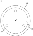
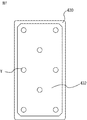
- the spacer has a rectangular shape, but it goes without saying that other shapes such as the above-mentioned circular shape are also applicable.
- the material of the iron core the one having an integral shape is exemplified, but it goes without saying that the same effect can be obtained even if a magnetic steel sheet or a magnetic steel sheet such as a cold rolled steel sheet is laminated and integrated.
Landscapes
- Physics & Mathematics (AREA)
- Electromagnetism (AREA)
- Engineering & Computer Science (AREA)
- Power Engineering (AREA)
- Electromagnets (AREA)
Abstract
Priority Applications (4)
| Application Number | Priority Date | Filing Date | Title |
|---|---|---|---|
| KR1020217010882A KR102427376B1 (ko) | 2018-10-25 | 2019-06-18 | 전자석, 전자 개폐기, 및 전자석의 제조 방법 |
| CN201980069192.2A CN112889122B (zh) | 2018-10-25 | 2019-06-18 | 电磁铁、电磁开闭器及电磁铁的制造方法 |
| JP2020552513A JP7002673B2 (ja) | 2018-10-25 | 2019-06-18 | 電磁石、電磁開閉器、電磁石の製造方法、および電磁開閉器の製造方法 |
| TW108131211A TWI688975B (zh) | 2018-10-25 | 2019-08-30 | 電磁鐵、電磁開關、及電磁鐵的製造方法 |
Applications Claiming Priority (2)
| Application Number | Priority Date | Filing Date | Title |
|---|---|---|---|
| JP2018-200494 | 2018-10-25 | ||
| JP2018200494 | 2018-10-25 |
Publications (1)
| Publication Number | Publication Date |
|---|---|
| WO2020084829A1 true WO2020084829A1 (fr) | 2020-04-30 |
Family
ID=70332206
Family Applications (1)
| Application Number | Title | Priority Date | Filing Date |
|---|---|---|---|
| PCT/JP2019/024024 Ceased WO2020084829A1 (fr) | 2018-10-25 | 2019-06-18 | Électroaimant, commutateur électromagnétique et procédé de fabrication d'électroaimant |
Country Status (5)
| Country | Link |
|---|---|
| JP (1) | JP7002673B2 (fr) |
| KR (1) | KR102427376B1 (fr) |
| CN (1) | CN112889122B (fr) |
| TW (1) | TWI688975B (fr) |
| WO (1) | WO2020084829A1 (fr) |
Cited By (1)
| Publication number | Priority date | Publication date | Assignee | Title |
|---|---|---|---|---|
| JPWO2022024565A1 (fr) * | 2020-07-28 | 2022-02-03 |
Families Citing this family (1)
| Publication number | Priority date | Publication date | Assignee | Title |
|---|---|---|---|---|
| WO2021260985A1 (fr) * | 2020-06-24 | 2021-12-30 | 三菱電機株式会社 | Mécanisme d'application de pression d'électrode pour machine de soudage par résistance, machine de soudage par résistance, procédé de soudage et procédé de production pour commutateur électromagnétique |
Citations (4)
| Publication number | Priority date | Publication date | Assignee | Title |
|---|---|---|---|---|
| JPS4851856A (fr) * | 1971-11-02 | 1973-07-20 | ||
| JPS56141515A (en) * | 1980-04-08 | 1981-11-05 | Yokogawa Hokushin Electric Corp | Displacement measuring device |
| JPS61125643A (ja) * | 1984-11-22 | 1986-06-13 | Nec Corp | メツセ−ジ表示装置 |
| JPS62145708A (ja) * | 1985-12-20 | 1987-06-29 | Mitsubishi Electric Corp | 電磁石装置 |
Family Cites Families (29)
| Publication number | Priority date | Publication date | Assignee | Title |
|---|---|---|---|---|
| JPS501852U (fr) * | 1973-05-04 | 1975-01-09 | ||
| JPS5846412A (ja) | 1981-09-11 | 1983-03-17 | Toshiba Corp | 運転操作装置 |
| JPS5846412U (ja) * | 1981-09-24 | 1983-03-29 | 三菱電機株式会社 | 電磁石 |
| JPS6254406A (ja) * | 1985-07-29 | 1987-03-10 | Mitsubishi Electric Corp | 電磁石鉄心 |
| JPS62145706A (ja) * | 1985-12-20 | 1987-06-29 | Mitsubishi Electric Corp | 電磁石装置 |
| JPH0414890Y2 (fr) * | 1986-08-18 | 1992-04-03 | ||
| JP3014878B2 (ja) * | 1992-11-17 | 2000-02-28 | トヨタ自動車株式会社 | 焼入油の冷却装置 |
| JP3166559B2 (ja) * | 1994-10-25 | 2001-05-14 | 富士電機株式会社 | 電磁接触器の電磁石装置 |
| JPH11191352A (ja) * | 1997-12-26 | 1999-07-13 | Mitsubishi Electric Corp | 電磁石 |
| JP2003007528A (ja) * | 2001-06-26 | 2003-01-10 | Keihin Corp | 電磁装置 |
| JP3987039B2 (ja) | 2004-01-13 | 2007-10-03 | 株式会社ケーヒン | 燃料噴射弁 |
| CN101079352A (zh) * | 2006-05-26 | 2007-11-28 | 盛润泉 | 一种新型交、直流接触器 |
| JP5163317B2 (ja) * | 2008-06-30 | 2013-03-13 | オムロン株式会社 | 接点装置 |
| JP5163318B2 (ja) * | 2008-06-30 | 2013-03-13 | オムロン株式会社 | 電磁石装置 |
| CN101677044B (zh) * | 2008-09-19 | 2011-12-28 | 厦门宏发电力电器有限公司 | 一种高可靠长寿命的高压直流真空继电器 |
| WO2010073317A1 (fr) * | 2008-12-24 | 2010-07-01 | 三菱電機株式会社 | Contacteur électromagnétique |
| EP2570707B1 (fr) * | 2010-12-06 | 2016-12-28 | Eagle Industry Co., Ltd. | Électrovanne |
| JP2013045855A (ja) * | 2011-08-23 | 2013-03-04 | Takigen Mfg Co Ltd | ソレノイド装置 |
| JP5964419B2 (ja) * | 2012-05-17 | 2016-08-03 | 三菱電機株式会社 | 電磁開閉器 |
| WO2013175653A1 (fr) * | 2012-05-21 | 2013-11-28 | 三菱電機株式会社 | Dispositif électromagnétique et dispositif de commutation utilisant ledit dispositif électromagnétique |
| WO2014068625A1 (fr) * | 2012-11-05 | 2014-05-08 | 三菱電機株式会社 | Contacteur électromagnétique |
| EP2975617B1 (fr) * | 2013-03-13 | 2023-06-07 | Mitsubishi Electric Corporation | Dispositif actionné par solénoïde |
| JP5734537B1 (ja) * | 2014-09-25 | 2015-06-17 | 三菱電機株式会社 | 電磁接触器及び電磁接触器の組立方法 |
| CN106716564B (zh) * | 2014-09-30 | 2019-03-08 | 三菱电机株式会社 | 线圈轴及电磁铁装置 |
| JP2017050274A (ja) * | 2015-09-04 | 2017-03-09 | オムロン株式会社 | 接点開閉装置 |
| CN105551892A (zh) * | 2016-02-22 | 2016-05-04 | 南京宁甬天星汽车电器有限公司 | 高效电磁铁 |
| CN206742158U (zh) * | 2017-04-27 | 2017-12-12 | 贵州天义电器有限责任公司 | 一种螺管式接触器 |
| CN107403707A (zh) * | 2017-08-25 | 2017-11-28 | 戴丁志 | 稳磁式接触器 |
| JP2021031506A (ja) * | 2019-08-13 | 2021-03-01 | 旭化成株式会社 | 熱可塑性樹脂組成物、成形体 |
-
2019
- 2019-06-18 JP JP2020552513A patent/JP7002673B2/ja active Active
- 2019-06-18 CN CN201980069192.2A patent/CN112889122B/zh active Active
- 2019-06-18 KR KR1020217010882A patent/KR102427376B1/ko active Active
- 2019-06-18 WO PCT/JP2019/024024 patent/WO2020084829A1/fr not_active Ceased
- 2019-08-30 TW TW108131211A patent/TWI688975B/zh active
Patent Citations (4)
| Publication number | Priority date | Publication date | Assignee | Title |
|---|---|---|---|---|
| JPS4851856A (fr) * | 1971-11-02 | 1973-07-20 | ||
| JPS56141515A (en) * | 1980-04-08 | 1981-11-05 | Yokogawa Hokushin Electric Corp | Displacement measuring device |
| JPS61125643A (ja) * | 1984-11-22 | 1986-06-13 | Nec Corp | メツセ−ジ表示装置 |
| JPS62145708A (ja) * | 1985-12-20 | 1987-06-29 | Mitsubishi Electric Corp | 電磁石装置 |
Cited By (3)
| Publication number | Priority date | Publication date | Assignee | Title |
|---|---|---|---|---|
| JPWO2022024565A1 (fr) * | 2020-07-28 | 2022-02-03 | ||
| WO2022024565A1 (fr) * | 2020-07-28 | 2022-02-03 | 三菱電機株式会社 | Procédé de fabrication d'un commutateur électromagnétique et commutateur électromagnétique |
| JP7321380B2 (ja) | 2020-07-28 | 2023-08-04 | 三菱電機株式会社 | 電磁開閉器の製造方法 |
Also Published As
| Publication number | Publication date |
|---|---|
| JPWO2020084829A1 (ja) | 2021-04-08 |
| KR102427376B1 (ko) | 2022-07-29 |
| JP7002673B2 (ja) | 2022-02-04 |
| TWI688975B (zh) | 2020-03-21 |
| KR20210049934A (ko) | 2021-05-06 |
| TW202016958A (zh) | 2020-05-01 |
| CN112889122B (zh) | 2022-10-28 |
| CN112889122A (zh) | 2021-06-01 |
Similar Documents
| Publication | Publication Date | Title |
|---|---|---|
| JP7398113B2 (ja) | 磁気式クランプ装置及び磁気式クランプ装置用磁力発生機構 | |
| JP2022546547A (ja) | 血液ポンプ | |
| US20100225431A1 (en) | Steel having non-magnetic portion, its producing method, and revolving electric core | |
| JP5949930B2 (ja) | インダイレクトスポット溶接方法 | |
| EP2600506A2 (fr) | Procédé de fabrication d'un stator pour moteur et stator pour moteur | |
| JP2016140240A (ja) | 小型電気駆動装置、軟磁性磁気帰還路装置および軟磁性磁気帰還路装置の製造方法 | |
| WO2020084829A1 (fr) | Électroaimant, commutateur électromagnétique et procédé de fabrication d'électroaimant | |
| WO2019098305A1 (fr) | Procédé de soudage par points | |
| JP2005312286A (ja) | リニアアクチュエータ | |
| JP2019537512A (ja) | シートの積層を磁気パルスで溶接する方法 | |
| US12100546B2 (en) | Method for producing a magnetic core for an electromagnetic actuator | |
| JP5455690B2 (ja) | 電磁コイル、電子レンズ、および電磁バルブ | |
| JPH0215750B2 (fr) | ||
| US4631809A (en) | Process for manufacture cores of electromagnet | |
| JP4494883B2 (ja) | ロータの製造方法及びその装置 | |
| KR102380119B1 (ko) | 초박판 고정을 위한 유도자석식 고정 지그 및 이의 운용방법 | |
| JPS6339930Y2 (fr) | ||
| JP7321380B2 (ja) | 電磁開閉器の製造方法 | |
| JP2006339381A (ja) | ソレノイド及びソレノイドの製造方法 | |
| US20230317346A1 (en) | Tie plate for a transformer core assembly | |
| JPS5893305A (ja) | 電磁石装置 | |
| JPS6325689B2 (fr) | ||
| JP2004260924A (ja) | リニアアクチュエータ | |
| JP2013194827A (ja) | 電磁弁 | |
| JPS6254406A (ja) | 電磁石鉄心 |
Legal Events
| Date | Code | Title | Description |
|---|---|---|---|
| 121 | Ep: the epo has been informed by wipo that ep was designated in this application |
Ref document number: 19877131 Country of ref document: EP Kind code of ref document: A1 |
|
| ENP | Entry into the national phase |
Ref document number: 2020552513 Country of ref document: JP Kind code of ref document: A |
|
| ENP | Entry into the national phase |
Ref document number: 20217010882 Country of ref document: KR Kind code of ref document: A |
|
| NENP | Non-entry into the national phase |
Ref country code: DE |
|
| 122 | Ep: pct application non-entry in european phase |
Ref document number: 19877131 Country of ref document: EP Kind code of ref document: A1 |