WO2020084886A1 - 自動分析装置 - Google Patents
自動分析装置 Download PDFInfo
- Publication number
- WO2020084886A1 WO2020084886A1 PCT/JP2019/033233 JP2019033233W WO2020084886A1 WO 2020084886 A1 WO2020084886 A1 WO 2020084886A1 JP 2019033233 W JP2019033233 W JP 2019033233W WO 2020084886 A1 WO2020084886 A1 WO 2020084886A1
- Authority
- WO
- WIPO (PCT)
- Prior art keywords
- dispensing
- sample
- analysis
- standard substance
- automatic analyzer
- Prior art date
- Legal status (The legal status is an assumption and is not a legal conclusion. Google has not performed a legal analysis and makes no representation as to the accuracy of the status listed.)
- Ceased
Links
Images


Classifications
-
- G—PHYSICS
- G01—MEASURING; TESTING
- G01N—INVESTIGATING OR ANALYSING MATERIALS BY DETERMINING THEIR CHEMICAL OR PHYSICAL PROPERTIES
- G01N35/00—Automatic analysis not limited to methods or materials provided for in any single one of groups G01N1/00 - G01N33/00; Handling materials therefor
- G01N35/10—Devices for transferring samples or any liquids to, in, or from, the analysis apparatus, e.g. suction devices, injection devices
- G01N35/1009—Characterised by arrangements for controlling the aspiration or dispense of liquids
- G01N35/1016—Control of the volume dispensed or introduced
-
- G—PHYSICS
- G01—MEASURING; TESTING
- G01N—INVESTIGATING OR ANALYSING MATERIALS BY DETERMINING THEIR CHEMICAL OR PHYSICAL PROPERTIES
- G01N35/00—Automatic analysis not limited to methods or materials provided for in any single one of groups G01N1/00 - G01N33/00; Handling materials therefor
- G01N2035/00465—Separating and mixing arrangements
- G01N2035/00564—Handling or washing solid phase elements, e.g. beads
-
- G—PHYSICS
- G01—MEASURING; TESTING
- G01N—INVESTIGATING OR ANALYSING MATERIALS BY DETERMINING THEIR CHEMICAL OR PHYSICAL PROPERTIES
- G01N35/00—Automatic analysis not limited to methods or materials provided for in any single one of groups G01N1/00 - G01N33/00; Handling materials therefor
- G01N35/0098—Automatic analysis not limited to methods or materials provided for in any single one of groups G01N1/00 - G01N33/00; Handling materials therefor involving analyte bound to insoluble magnetic carrier, e.g. using magnetic separation
Definitions
- the present invention relates to an automatic analyzer that analyzes a sample.
- LC-MS liquid chromatography
- MS mass spectrometer
- a biological sample such as blood or urine (hereinafter simply referred to as a sample) by LC-MS
- pretreatment of the sample include methods such as solid phase extraction (SPE: Solid Phase Extraction) and liquid-liquid extraction (LLE: Liquid-Liquid Extraction).
- SPE Solid Phase Extraction
- LLE Liquid-Liquid Extraction
- a sample disc having a sample container, a reagent disc having a reagent container, and a measurement target component of the sample are described.
- An analyzer including a mass spectrometer that measures a sample purified in a container is disclosed.
- various solutions related to analysis are performed by dispensing a predetermined amount of sample or reagent solution into a reaction container.
- a deproteinization treatment for denaturing and precipitating the protein in blood is performed by adding a reagent such as an organic solvent as a deproteinizing agent to the blood dispensed in the reaction vessel.
- a reagent such as an organic solvent as a deproteinizing agent
- the amount of the sample, reagent and the like dispensed into the reaction container is small, the influence of the dispensing accuracy on the analysis result is inevitably large. For example, when the dispensed amount of the reagent is smaller than a predetermined amount, the amount of the drug to be eluted is reduced to show a false low value, which may reduce the analysis accuracy.
- the present invention has been made in view of the above, and an automatic analyzer and an analysis that can reliably detect an abnormality in the dispensed amount of a solution such as a sample or a reagent to be dispensed and can suppress a decrease in analysis accuracy
- the purpose is to provide a method.
- the present invention provides a first dispensing mechanism for dispensing a sample to be analyzed into a reaction container, and a second dispensing mechanism for dispensing another dispensing target different from the sample into the reaction container.
- a dispensing mechanism an analysis mechanism for detecting and analyzing a specific component in the reaction solution in which the sample dispensed in the reaction container and the other dispensing target are mixed, and a controller.
- the control device is for detecting a dispensing test previously added to the other dispensing target, which is detected at the same time as the detection of the analyte component of the sample in the reaction solution in the analysis mechanism. Based on the detection result of the standard substance, it is determined whether or not the dispensing liquid amount of the other dispensing target is abnormal.
- Abnormality of the dispensed amount of the solution such as the sample or reagent to be dispensed can be reliably detected, and a decrease in analysis accuracy can be suppressed.
- FIG. 1 It is a figure which shows schematically the whole structure of the automatic analyzer which concerns on one embodiment of this invention. It is a figure which shows an example of the pretreatment process of the analysis process by an automatic analyzer. It is a figure which shows the case where the mass chromatograms which originate in each of the dispensing inspection standard substance, the internal standard substance, and a standard substance are compared. It is a figure which shows the case where the mass chromatogram derived from each of the dispensing inspection standard substance, the internal standard substance, and the analysis object component was compared. It is a figure which shows the case where the mass chromatogram derived from each of the dispensing inspection standard substance, the internal standard substance, and the analysis object component was compared.
- an automatic analyzer in which the sample pretreatment function is combined with LC-MS (Liquid Chromatography-Mass Spectrometry) as an analysis mechanism will be described as an example.
- LC-MS Liquid Chromatography-Mass Spectrometry
- capillary electrophoresis or the like can be used as an analysis mechanism.
- the present invention can also be applied to an automatic analyzer that combines the separating means described above and a detector such as an absorptiometer.
- a deproteinizing agent will be described as an example of a target to which a dispensing test standard substance is added, but, for example, an internal standard substance, magnetic beads, or the like is dispensed to a sample during analysis.
- the present invention can be applied to all solutions.
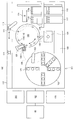
- FIG. 1 is a diagram schematically showing the overall configuration of the automatic analyzer according to the present embodiment.
- an automatic analyzer 100 includes an analyzer 101 for performing an analysis operation, a controller 102 for controlling the operation of the entire apparatus, an input unit 103 for a user to input information to the apparatus, A display unit 104 for displaying information to a user and a storage unit 105 such as a storage medium for storing various information related to control of the automatic analyzer 100 are roughly configured.
- the control unit 102, the input unit 103, the display unit 104, and the storage unit 105 constitute a control device that controls the overall operation of the automatic analyzer 100.
- the input unit 103 and the display unit 104 are shown as separate bodies in the present embodiment, the input unit 103 and the display unit 104 may be integrally formed, for example, as in a touch panel monitor. Good.
- the analysis unit 101 mounts the sample container 111 accommodating the sample to be analyzed to the sample dispensing position, and the reaction container 116 by mounting the reaction container 116 in the plurality of openings 119.
- a reaction container disk 120 capable of holding a constant temperature
- a sample dispensing mechanism 113 that dispenses a sample to the sample 116, a reagent dispensing mechanism 123 that dispenses a reagent from the reagent container 121 to the reaction container 116 of the reaction container disk 120, and a nozzle of the sample dispensing mechanism 113 are mounted.
- Dispensing tip mounting rack 115 on which disposable dispensing tips 115a are unused and a nozzle of the sample dispensing mechanism 113 From the used dispensing tip 115a and discarding it, or mounting the unused dispensing tip 115a on the nozzle, and mounting and dismounting the dispensing tip 114, and mounting the unused reaction vessel 116 on the reaction vessel
- the magnetic separation mechanism 124 is provided on the rotation track 126 of the reagent dispensing mechanism 123.
- the reagent dispensing mechanism 123 can discharge a reagent into the reaction container 116 supported by the magnetic separation mechanism 124 or suck a solution in the reaction container 116.
- the reaction container disk 120 functions as an incubator for keeping the temperature of the reaction container 116 installed in the opening 119 constant, and incubates the reaction container 116 installed in the opening 119 for a certain time.
- the separating unit 131 is, for example, LC (Liquid Chromatography), and has a column or the like as a function of separating the components in the reaction solution dispensed by the dispensing mechanism 132 for the separating unit.
- the separating unit 131 separates the components in the reaction solution dispensed from the reaction container 116 by the separating unit dispensing mechanism 132, and sequentially introduces the separated components into the mass spectrometric unit 133.
- the mass spectrometric unit 133 is, for example, MS (Mass Spectrometry), and has an electron multiplier and the like as a function of ionizing and mass spectrometrically analyzing the components introduced from the separating unit 131.
- the mass spectrometric unit 133 ionizes the component introduced from the separation unit 131 to detect the ion amount (that is, the component amount), and outputs the detection result to the control unit 102.
- the control unit 102 calculates the concentration value of the component in the sample using the detection result (ion amount) from the mass spectrometry unit 133 and the calibration curve acquired in advance, and stores the concentration value in the storage unit 105 as the analysis result and the analysis result.
- the result is displayed on the display unit 104.
- a calibration curve for example, first, a standard substance of known concentration is analyzed for multiple concentrations. Then, with respect to the m / z (mass / charge ratio) of the ions derived from the standard substance, a time change (mass chromatogram) of the ion amount, that is, the ion intensity is acquired, and the peak area of the mass chromatogram is obtained. A calibration curve is created from the relationship between this area and the concentration of the standard substance. By using the calibration curve thus obtained, it is possible to detect the component concentration of a sample whose concentration is unknown and which has the same component to be analyzed as the standard substance.
- the peak area of the mass chromatogram is obtained for the sample to be analyzed, and the component concentration of the analysis target component is determined from the correspondence between the peak area of this mass chromatogram and the calibration curve. If the intensity of the detected ion is standardized based on the intensity of the ion derived from the internal standard substance, the comparison between the data can be performed with high accuracy. That is, it is possible to compare and verify the ionic strengths that may show a slight variation in each analysis due to the influence of the pretreatment of the sample, the injection of the sample into the LC-MS, the ionization in the LC-MS, and the like. . This method is called the internal standard method.
- FIG. 2 is a diagram showing an example of a pretreatment process of the analysis process by the automatic analyzer.
- an unused reaction container 116 is installed from the reaction container mounting rack 117 to the opening 119 on the reaction container disk 120 by the transport mechanism 118. Further, prior to the sample dispensing, the sample dispensing mechanism 113 is made to access the dispensing tip loading / unloading section 114, and the dispensing tip 115a is attached to the tip of the nozzle.
- the sample dispensing mechanism 113 sucks the sample containing the analysis target component 201 from the sample container 111 via the dispensing tip 115a and discharges it to the reaction container 116 of the reaction container disk 120 (step S200).
- the sample dispensing mechanism 113 finishes dispensing the sample from one sample container 111, the sample dispensing mechanism 113 discards the used dispensing tip 115a in the dispensing tip mounting / demounting unit 114, and also disposes the unused dispensing tip. 115a is attached.
- the reagent dispensing mechanism 123 sucks the internal standard substance 203 as a reagent corresponding to the analysis target component 201 from the reagent container 121 of the reagent disk 122 and discharges it to the reaction container 116 (step S201).
- the reagent dispensing mechanism 123 sucks the deproteinizing agent as a reagent from the reagent container 121 of the reagent disk 122 and discharges it to the reaction container 116 (step S202).
- the dispensing test standard substance 205 having a predetermined known concentration is added to the reagent container 121 containing the deproteinizing agent according to the present embodiment.
- the reagent dispensing mechanism 123 sucks the suspension of the magnetic beads 207 as a reagent from the reagent container 121 of the reagent disk 122 and discharges it to the reaction container 116 (step S205).
- the reaction vessel 116 into which the sample, the internal standard substance 203, and the magnetic beads 207 are dispensed is transported to the magnetic separation mechanism 124 by the transport mechanism 125, and the magnetic beads 207 are washed (step S205).
- the magnetic separation mechanism 124 the magnetic beads 207 holding the analysis target component 201, the internal standard substance 203, and the dispensing inspection standard substance 205 by the magnetic force of the magnet 209 arranged along the outer surface of the reaction container 116. Are collected on the inner wall surface of the reaction container 116 (shown as the magnetic bead group 210 in FIG. 2).
- the reagent dispensing mechanism 123 sucks the solution in the reaction container 116 and discards it.
- the magnetic beads 207, the analysis target component 201 held by the magnetic beads 207, the internal standard substance 203, and the dispensing inspection standard substance 205 remain in the reaction container 116.
- the reagent dispensing mechanism 123 removes impurities from the reagent container 121 of the reagent disk 122 other than the substances (the analysis target component 201, the internal standard substance 203, the dispensing inspection standard substance 205) held by the magnetic beads 207.
- the cleaning liquid to be cleaned is sucked and discharged into the reaction container 116.
- the constraint of the magnetic beads 207 due to the magnetic force of the magnet 209 may be temporarily released.
- the reagent dispensing mechanism 123 sucks and discards the solution (cleaning liquid) in the reaction container 116. Perform cleaning.
- the reagent dispensing mechanism 123 causes the reagent container 121 of the reagent disk 122 to use, as a reagent, an eluate that elutes the analysis target component 201, the internal standard substance 203, and the dispensing inspection standard substance 205 from the magnetic beads 207. It is sucked and discharged into the reaction container 116 (step S206).
- the reagent dispensing mechanism 123 sucks the solution (purified liquid) in the reaction container 116 and arranges it in the magnetic separation mechanism 124.
- the reaction container disc 120 different from the reaction container 116 is discharged to an unused reaction container 116 (step S207).
- the purified liquid contained in the reaction container 116 of the reaction container disk 120 is incubated if necessary.
- the purified liquid obtained by the above pretreatment process is sucked from the reaction container 116 by the separating unit dispensing mechanism 132 and discharged to the separating unit 131, and the components separated by the separating unit 131 are ionized by the mass spectrometry unit 133.
- the detection result of the mass spectrometric unit 133 is output to the control unit 102, and the concentration value of the component in the sample is calculated using the calibration curve.
- the dispensing amount abnormality determination process of the present embodiment is a process of determining whether or not there is an abnormality in the dispensing amount of a solution such as a reagent dispensed to a sample to be analyzed.
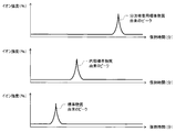
- FIGS. 3 to 5 are diagrams schematically showing an example of a mass chromatogram acquired by the analysis unit for each of the dispensing inspection standard substance, the internal standard substance, the standard substance, and the component to be analyzed.
- the axis shows the ionic strength and the horizontal axis shows the LC retention time.
- FIG. 3 shows a case where the standard substances for dispensing inspection, internal standard substances, and mass chromatograms derived from the respective standard substances are compared
- FIGS. 4 and 5 show standard substances for dispensing inspection, internal standard substances.
- the mass chromatograms derived from the respective components to be analyzed are compared.
- the dispensing inspection standard substance is added in advance to the solution (eg, deproteinizing agent) to be determined for dispensing amount abnormality.
- the solution eg, deproteinizing agent
- a substance that is detected at the same time as the analysis target component is selected within the range of the LC retention time in which the analysis target component of the sample that is the analysis target is detected.
- a standard substance of known concentration is analyzed according to the steps of the analysis process, and a mass chromatogram of the standard substance (see FIG. 3 etc.) is acquired in advance and recorded in the storage unit 105 as judgment reference data.
- acquired data data including peaks derived from the component to be analyzed of the sample and the internal standard substance (hereinafter, referred to as acquired data) is obtained.
- data including peaks derived from the standard substance for dispensing test are obtained within the same LC retention time range (see FIGS. 4 and 5).
- a difference ratio represented by the following (Formula 1) is defined as an index indicating the degree of mismatch between the determination reference data and the acquired data.
- the difference ratio given by (Equation 1) above is compared with a preset difference ratio threshold value, and it is determined whether there is an abnormality in the dispensing amount based on the comparison result. . That is, the presence or absence of an abnormality in the dispensing amount can be temporarily determined by calculating the difference ratio at the same time as calculating the analysis target component concentration and comparing the difference ratio with the difference ratio threshold.
- the difference ratio threshold serving as the determination standard is set in advance prior to the analysis process and the dispensing amount abnormality determination process, and is stored in the storage unit 105 similarly to the determination reference data. It should be noted that the operator may be able to input as appropriate. It is known that the standard measurement error of LC-MS is about 5 to 10%. Therefore, in the present embodiment, a case where the difference ratio threshold is set to 15% will be described as an example. That is, when the difference ratio exceeds 15%, it is determined that the dispensing amount is abnormal. Since it is considered that the measurement error depends on the device, a difference ratio threshold value may be set for each device to further improve the accuracy of determination of the dispensing amount abnormality.
- the peak area derived from the dispensing inspection standard substance is larger than that of the determination reference data.
- the difference ratio threshold value 15%), it is determined that there is an abnormality that the dispensed amount of the deproteinizing agent containing the dispense test standard substance increases.
- the amount of deproteinizing agent for eluting the component to be analyzed is sufficient when the amount to be analyzed is normal, even if the amount of deproteinizing agent is increased, Since the elution amount does not change, the peak area derived from the component to be analyzed does not change.
- the peak area derived from the dispensing inspection standard substance is more than that of the determination reference data. There is a decrease in the data acquired during sample analysis. Therefore, when the difference ratio exceeds the difference ratio threshold value (15%), it is determined that there is an abnormality that the dispensed amount of the deproteinizing agent containing the dispense test standard substance decreases. Further, the peak area derived from the component to be analyzed also decreases.
- the concentration of the component to be analyzed is calculated to be low. In this case, even if the data derived from the components to be analyzed are standardized with the data derived from the internal standard by the internal standard method, it is not possible to correct the variation in the amount of the deproteinization agent dispensed, so the dispensing test It may be corrected by normalizing the data derived from the component to be analyzed with the data derived from the standard substance.
- MS it is common to use a stable isotope compound as an internal standard substance, which is an isotope-labeled analyte, or a compound having similar chemical and physical properties (hereinafter referred to as an analog compound). Therefore, in consideration of that point when selecting the standard substance for dispensing inspection, it is possible to capture it with magnetic beads during the pretreatment of the sample, and it is derived from the component to be analyzed and the internal standard substance in the mass chromatogram. A substance that is sufficiently separated from the peak and that is detected within the retention time range of the LC measured for the analyte is selected as the standard substance for dispensing inspection.
- the analysis target component is captured by the hydrophobic interaction with the magnetic beads.
- a reverse phase column is usually used as a separation column. Retention on a reverse phase column is basically based on hydrophobic interactions. Therefore, for example, it is desirable that the standard substance for dispensing test has a hydrophobicity that can be captured by the magnetic beads and the reverse phase column to the same extent as the analysis target component.
- an ionic compound in a non-dissociated state generally has high hydrophobicity, so that retention on a reversed-phase column also becomes strong. The difference between the dissociated state and the non-dissociated state arises from the relationship between the pH of the LC mobile phase and the pKa of the compound.
- the retention behavior can be stabilized by setting the pKa of the component to be analyzed and the internal standard substance to be a value separated from the pH of the mobile phase by ⁇ 2 or more. That is, in consideration of the above, from the balance between the pKa of the component to be analyzed and the internal standard substance and the mobile phase, the peak derived from the component to be analyzed and the internal standard substance in the chromatogram is sufficiently separated, and the component to be analyzed is It is important to select a substance that can be detected within the range of the LC retention time to measure as a standard substance for dispensing inspection.
- the peak intensity of the ion derived from the standard substance for dispensing inspection will be There is a possibility that it will be erroneously recognized as increased. In this case, it becomes difficult to determine whether or not there is an abnormality in the dispensing amount.
- the mass resolution of ordinary MS is about 1 (m / z)
- the peak m / z of the mass chromatogram derived from the components to be analyzed, the internal standard substance, and the standard substance for dispensing inspection is at least 1 [Da]
- the distance is 3 [Da] or more.
- the MS used as a detector uses an apparatus equipped with an MS / MS method capable of detecting product ions. Is desirable.
- the MS / MS method is used, even if the precursor ions of each substance have the same m / z, the product ions may have different m / z.
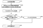
- FIG. 6 is a flowchart showing the analysis process including the dispensing amount abnormality determination process according to the present embodiment.
- the control unit 102 when the input unit 103 or the like instructs the start of the analysis process (step S601), the control unit 102 includes dispensing of a sample to be analyzed or a reagent containing a dispensing inspection standard substance.
- a pretreatment process (see FIG. 2) is performed (step S602).
- the pretreatment-treated solution is dispensed from the reaction vessel 116 to the separation section 131 by the separation section dispensing mechanism 132, and mass spectrometry of the components in the solution separated by the separation section 131 in the mass spectrometric section 133 is performed. Grams are acquired (step S603).
- a mass chromatogram of the dispensing inspection standard substance is obtained together with a mask rotogram of the analysis target component of the sample.
- the difference ratio between the determination standard data and the acquired data of the dispensing inspection standard substance is calculated, and it is determined whether the difference ratio is smaller than the difference ratio threshold value (step S604).
- step S604 If the determination result in step S604 is YES, it is determined that there is no abnormality in the dispensing amount of the reagent containing the dispensing inspection standard substance in the preprocessing, and the analysis result is stored in the storage unit 105 or displayed. After displaying on the unit 104, the analysis process is ended (step S605).
- step S604 If the determination result in step S604 is NO, it is determined that there was an abnormality in the dispensing amount of the reagent containing the standard substance for dispensing inspection in the pretreatment, and the analysis result indicates that the dispensing amount is abnormal.
- a data flag indicating that it is determined to exist is added (step S606), the analysis result is stored in the storage unit 105 or displayed on the display unit 104, and then the analysis process ends (step S605).
- FIG. 7 is a diagram showing an example of the analysis result displayed on the display unit.
- the analysis results displayed on the display unit 104 include, as a measurement value list, sample numbers for identifying samples to be analyzed, and analysis items corresponding to the analysis processing performed on each sample.
- the date and time when the measurement is performed and the measured value, which is the component amount of the analysis target component contained in the analysis target sample, are displayed in association with each other.
- the analysis result for example, the sample No. 10 in FIG. 7 determined that there is an abnormality in the dispensing amount of the solution other than the sample in the abnormality determination process of the dispensing amount in the analysis process, there is an abnormality in the dispensing amount.
- a data flag indicating that the determination has been made (for example, “abnormal dispensing amount” in the remarks column) is added and displayed.
- the additional alarm information includes the sample number for which the abnormality was determined, and the content of the abnormality (here, dispensing amount abnormality). , And a description of the details of the abnormality are displayed.
- a predetermined amount of sample or reagent solution is dispensed into a reaction container to perform various processing related to analysis.
- a deproteinization treatment for denaturing and precipitating the protein in blood is performed by adding a reagent such as an organic solvent as a deproteinizing agent to the blood dispensed in the reaction vessel.
- a reagent such as an organic solvent as a deproteinizing agent
- the amount of the sample, reagent and the like dispensed into the reaction container is small, the influence of the dispensing accuracy on the analysis result is inevitably large. For example, when the dispensed amount of the reagent is smaller than a predetermined amount, the amount of the drug to be eluted is reduced to show a false low value, which may reduce the analysis accuracy.
- the sample dispensing mechanism 113 (first dispensing mechanism) that dispenses the sample to be analyzed into the reaction container 116 and another dispensing device different from the sample in the reaction container 116.
- a reagent dispensing mechanism 123 (second dispensing mechanism) for dispensing the target and a specific component in the reaction solution in which the sample dispensed in the reaction container 116 and another dispensing target are mixed are detected.
- Mass spectrometric unit 133 (analytical mechanism) for performing analysis by means of a mass spectrometric analysis unit 133, and for dispensing inspection that is detected in the mass spectrometric unit 133 at the same time as detection of a component to be analyzed of a sample in a reaction solution Since the control unit 102 (control device) that determines whether or not the amount of the dispensed liquid to be dispensed is abnormal based on the detection result of the standard substance is used, Reliably detects abnormalities in the dispensed amount of solutions such as reagents, and suppresses deterioration of analysis accuracy Rukoto can.
- the detection result of the pressure sensor provided inside the dispensing nozzle of the dispensing mechanism is compared with reference data for determination, and the abnormality is detected based on the comparison result.
- a method can be considered.
- this method since it is necessary to use a pressure sensor that detects the pressure inside the dispensing nozzle of the dispensing mechanism, extra cost and space are required to provide the pressure sensor in the device.
- the cost and space of the pressure sensor are required according to the number of dispensing mechanisms for which an abnormality is to be detected.
- the cost and space of the pressure sensor are unnecessary, and while suppressing an increase in cost and space, an abnormal dispensing amount of the solution such as the sample or reagent to be dispensed is prevented. It is possible to reliably detect and suppress deterioration of analysis accuracy.
- a dispensing target of a liquid amount for example, 1 [ul] to 1000 [ul]
- a standard validation method is dispensed. It is also conceivable that the calibration accuracy of the dispensed amount can be improved because the effect of evaporation is small by performing the assay based on the dye method.
- this method since it is necessary to carry out the assay at a different timing from the analysis of the sample, it is difficult to evaluate the validity of the actual measurement for analyzing the sample. Further, since the analysis of the sample is stopped during the execution of the assay, the throughput is reduced, and further, the labor for performing the assay is required for the user.
- the present embodiment since it is possible to determine whether or not there is an abnormality in the dispensed amount at the same time as the analysis of the sample, it is possible to evaluate the validity of the actual measurement of the analysis, It is possible to suppress a decrease in throughput and an increase in user's labor, to reliably detect an abnormality in the dispensed amount of a solution such as a sample or a reagent to be dispensed, and to suppress a decrease in analysis accuracy.
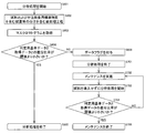
- This modification is to switch to the maintenance mode in addition to adding a data flag when it is determined that there is an abnormality in the dispensing amount.
- FIG. 8 is a flowchart showing the analysis process including the dispensing amount abnormality determination process according to this modification.
- the control unit 102 when the input unit 103 or the like issues an instruction to start the analysis process (step S601), the control unit 102 includes dispensing of a sample to be analyzed or a reagent containing a dispensing inspection standard substance.
- a pretreatment process (see FIG. 2) is performed (step S602).
- the pretreatment-treated solution is dispensed from the reaction vessel 116 to the separation section 131 by the separation section dispensing mechanism 132, and mass spectrometry of the components in the solution separated by the separation section 131 in the mass spectrometric section 133 is performed. Grams are acquired (step S603).
- a mass chromatogram of the dispensing inspection standard substance is obtained together with a mask rotogram of the analysis target component of the sample.
- the difference ratio between the determination standard data and the acquired data of the dispensing inspection standard substance is calculated, and it is determined whether the difference ratio is smaller than the difference ratio threshold value (step S604).
- step S604 If the determination result in step S604 is YES, it is determined that there is no abnormality in the dispensing amount of the reagent containing the dispensing inspection standard substance in the preprocessing, and the analysis result is stored in the storage unit 105 or displayed. After displaying on the unit 104, the analysis process is ended (step S605).
- step S604 If the determination result in step S604 is NO, it is determined that there was an abnormality in the dispensing amount of the reagent containing the standard substance for dispensing inspection in the pretreatment, and the analysis result indicates that the dispensing amount is abnormal.
- a data flag indicating that it is determined to exist is added (step S606), the analysis result is stored in the storage unit 105 or displayed on the display unit 104, and then the analysis process ends (step S701).
- the maintenance mode is switched to the maintenance of the automatic analyzer 100 (step S702).
- the maintenance mode is used for maintenance to automatically perform the cleaning of the dispensing nozzle and the peripheral flow path of the dispensing mechanism that is judged to be abnormal, or to replace the parts of the dispensing mechanism. It is a mode to prepare.
- step S703 the analysis process is started without introducing the sample to obtain a mass chromatogram (step S703), and the difference ratio between the determination standard data and the acquired data of the dispensing inspection standard substance is calculated to obtain the difference ratio. Is smaller than the difference ratio threshold value (step S704).
- step S704 If the determination result in step S704 is NO, the maintenance is performed again, and the processes in steps S702 to S704 are repeated until it is determined that there is no abnormality in the dispensing amount.
- step S704 If the decision result in the step S704 is YES, the maintenance mode is ended and the maintenance is ended (step S705).
- 100 Automatic analysis device, 101 ... Analysis part, 102 ... Control part, 103 ... Input part, 104 ... Display part, 105 ... Storage part, 111 ... Sample container, 112 ... Conveyance mechanism, 113 ... Sample dispensing mechanism, 114 ... Dispensing chip loading / unloading section, 115 ... Dispensing chip mounting rack, 115a ... Dispensing chip, 116 ... Reaction container, 117 ... Reaction container mounting rack, 118 ... Conveying mechanism, 119 ... Opening part, 120 ... Reaction container disk, 121 ... Reagent container, 122 ... Reagent disk, 123 ... Reagent dispensing mechanism, 124 ... Magnetic separation mechanism, 125 ...
- Conveyance mechanism 126 ... Rotation orbit, 131 ... Separation section, 132 ... Separation section dispensing mechanism, 133 ... Mass spectrometry Part, 201 ... Analyte target component, 203 ... Internal standard substance, 205 ... Dispensing inspection standard substance, 207 ... Magnetic beads, 209 ... Magnet, 210 ... Magnetic bead group
Landscapes
- Physics & Mathematics (AREA)
- Health & Medical Sciences (AREA)
- Life Sciences & Earth Sciences (AREA)
- Chemical & Material Sciences (AREA)
- Analytical Chemistry (AREA)
- Biochemistry (AREA)
- General Health & Medical Sciences (AREA)
- General Physics & Mathematics (AREA)
- Immunology (AREA)
- Pathology (AREA)
- Automatic Analysis And Handling Materials Therefor (AREA)
- Other Investigation Or Analysis Of Materials By Electrical Means (AREA)
Abstract
Description

本実施の形態の分注量異常判定処理では、上記の(式1)で与えられる差分比率を予め設定した差分比率閾値と比較し、比較結果に基づいて分注量の異常の有無を判定する。すなわち、分析対象成分濃度を算出するのと同時に差分比率を算出し、差分比率閾値と比較することで分注量の異常の有無を一時に判定することができる。
本実施の形態の変形例を図8を参照しつつ説明する。本変形例では、本実施の形態との相違点についてのみ説明するものとし、図面における本実施の形態と同様の部材には同じ符号を付し、説明を省略する。
なお、本発明は上記した実施の形態や変形例に限定されるものではなく、他の様々な変形例が含まれる。例えば、上記した実施の形態は本願発明を分かりやすく説明するために詳細に説明したものであり、必ずしも説明した全ての構成を備えるものに限定されるものではない。また、上記の各構成、機能等は、それらの一部又は全部を、例えば集積回路で設計する等により実現してもよい。また、上記の各構成、機能等は、プロセッサがそれぞれの機能を実現するプログラムを解釈し、実行することによりソフトウェアで実現してもよい。
Claims (7)
- 分析対象の試料を反応容器に分注する第一の分注機構と、
前記反応容器に前記試料と異なる他の分注対象を分注する第二の分注機構と、
前記反応容器に分注された前記試料と前記他の分注対象とが混合された反応溶液中の特定の成分を検出して分析を行う分析機構と、
制御装置とを備えた自動分析装置において、
前記制御装置は、前記分析機構において前記反応溶液中の前記試料の分析対象成分の検出と同時に検出される、前記他の分注対象に予め添加された分注検査用標準物質の検出結果に基づいて、前記他の分注対象の分注液量が異常であるか否かを判定することを特徴とする自動分析装置。 - 請求項1に記載の自動分析装置において、
前記制御装置は、予め定めた複数の判定用基準データと前記分注検査用標準物質の検出結果との差分と、予め定めた閾値とを比較した比較結果に基づいて前記他の分注対象の分注液量が異常であるか否かを判定することを特徴とする自動分析装置。 - 請求項2に記載の自動分析装置において、
前記制御装置は、前記差分が予め定めた閾値よりも大きい場合に、前記試料の分析対象成分の分析結果に前記他の分注対象の分注液量が異常である可能性を示すデータフラグを付与することを特徴とする自動分析装置。 - 請求項2に記載の自動分析装置において、
前記制御装置は、前記差分が予め定めた閾値よりも大きい場合に、前記試料の分析を行わずにメンテナンスを実行するメンテナンスモードに切り替えることを特徴とする自動分析装置。 - 請求項1に記載の自動分析装置において、
前記分注検査用標準物質は、磁性ビーズおよびカラムで捕捉することができ、前記分析機構により分析対象成分と分離して検出することができることを特徴とする自動分析装置。 - 請求項1に記載の自動分析装置において、
前記分注検査用標準物質は、疎水性を有し、前記他の分注対象に予め定めた濃度で添加されていることを特徴とする自動分析装置。 - 反応容器に分注された分析対象の試料と該試料とは異なる他の分注対象とが混合された反応溶液中の前記試料の分析対象成分の検出と同時に検出される、前記他の分注対象に予め添加された分注検査用標準物質の検出結果に基づいて、前記他の分注対象の分注液量が異常であるか否かを判定する分析方法。
Priority Applications (3)
| Application Number | Priority Date | Filing Date | Title |
|---|---|---|---|
| CN201980067999.2A CN112912736B (zh) | 2018-10-25 | 2019-08-26 | 自动分析装置 |
| JP2020552561A JP7232841B2 (ja) | 2018-10-25 | 2019-08-26 | 自動分析装置 |
| EP19876425.0A EP3872500B1 (en) | 2018-10-25 | 2019-08-26 | Automated analyzer |
Applications Claiming Priority (2)
| Application Number | Priority Date | Filing Date | Title |
|---|---|---|---|
| JP2018200985 | 2018-10-25 | ||
| JP2018-200985 | 2018-10-25 |
Publications (1)
| Publication Number | Publication Date |
|---|---|
| WO2020084886A1 true WO2020084886A1 (ja) | 2020-04-30 |
Family
ID=70331359
Family Applications (1)
| Application Number | Title | Priority Date | Filing Date |
|---|---|---|---|
| PCT/JP2019/033233 Ceased WO2020084886A1 (ja) | 2018-10-25 | 2019-08-26 | 自動分析装置 |
Country Status (5)
| Country | Link |
|---|---|
| US (1) | US12270822B2 (ja) |
| EP (1) | EP3872500B1 (ja) |
| JP (1) | JP7232841B2 (ja) |
| CN (1) | CN112912736B (ja) |
| WO (1) | WO2020084886A1 (ja) |
Cited By (4)
| Publication number | Priority date | Publication date | Assignee | Title |
|---|---|---|---|---|
| CN114660310A (zh) * | 2022-05-24 | 2022-06-24 | 深圳市帝迈生物技术有限公司 | 样本分析系统的自动定标方法 |
| WO2022230282A1 (ja) * | 2021-04-27 | 2022-11-03 | 株式会社日立ハイテク | 自動分析装置 |
| JP2024501976A (ja) * | 2020-12-30 | 2024-01-17 | ベックマン コールター, インコーポレイテッド | 単一の較正剤を用いた臨床検査室自動化システム |
| JP2024528532A (ja) * | 2021-06-29 | 2024-07-30 | ラジオメーター・メディカル・アー・ペー・エス | 予測保守システムおよび方法 |
Families Citing this family (1)
| Publication number | Priority date | Publication date | Assignee | Title |
|---|---|---|---|---|
| CN115146559B (zh) * | 2022-06-30 | 2025-04-25 | 哈尔滨工业大学 | 器件辐照缺陷演化分子动力学仿真的注量模拟方法及系统 |
Citations (6)
| Publication number | Priority date | Publication date | Assignee | Title |
|---|---|---|---|---|
| JP2007303937A (ja) * | 2006-05-10 | 2007-11-22 | Olympus Corp | 自動分析装置 |
| US20080217254A1 (en) * | 2007-03-05 | 2008-09-11 | Anderson N Leigh | Magnetic Bead Trap and Mass Spectrometer Interface |
| US20090130679A1 (en) * | 2007-11-20 | 2009-05-21 | Quanta Computer Inc. | Automated system and method for processing genetic material |
| JP2011153944A (ja) * | 2010-01-28 | 2011-08-11 | Hitachi High-Technologies Corp | 自動分析装置 |
| WO2011108177A1 (ja) | 2010-03-03 | 2011-09-09 | 株式会社 日立ハイテクノロジーズ | 分析装置 |
| JP2011179983A (ja) * | 2010-03-01 | 2011-09-15 | Beckman Coulter Inc | 標準粒子および自動分析装置 |
Family Cites Families (15)
| Publication number | Priority date | Publication date | Assignee | Title |
|---|---|---|---|---|
| JPH08145763A (ja) * | 1994-11-24 | 1996-06-07 | Sanyo Electric Co Ltd | 分注機の液面位検出装置 |
| JP2000065797A (ja) | 1998-08-20 | 2000-03-03 | Shimadzu Corp | クロマトグラフ質量分析装置の検量線作成方法 |
| CA2434094A1 (en) | 2001-01-29 | 2002-08-08 | Metara, Inc. | Automated in-process isotope and mass spectrometry |
| JP4021335B2 (ja) * | 2003-01-31 | 2007-12-12 | ユニバーサル・バイオ・リサーチ株式会社 | 監視機能付分注装置および分注装置の監視方法 |
| US7964413B2 (en) * | 2005-03-10 | 2011-06-21 | Gen-Probe Incorporated | Method for continuous mode processing of multiple reaction receptacles in a real-time amplification assay |
| WO2008044311A1 (en) * | 2006-10-13 | 2008-04-17 | Olympus Corporation | Method for identifying abnormal state, analytical apparatus, and reagent |
| JP2010112832A (ja) * | 2008-11-06 | 2010-05-20 | Beckman Coulter Inc | 自動分析装置 |
| US9383376B2 (en) * | 2008-12-09 | 2016-07-05 | Hitachi High-Technologies Corporation | Automatic analyzer |
| US8268264B2 (en) * | 2009-02-09 | 2012-09-18 | Caprotec Bioanalytics Gmbh | Devices, systems and methods for separating magnetic particles |
| DE112010000814B4 (de) * | 2009-02-10 | 2021-09-09 | Hitachi High-Tech Corporation | Immunanalytisches Verfahren und immunanalytisches System mit Verwendung der Massenspektrometertechnologie |
| WO2015174226A1 (ja) * | 2014-05-15 | 2015-11-19 | 株式会社日立ハイテクノロジーズ | 自動分析装置 |
| WO2016182034A1 (ja) * | 2015-05-12 | 2016-11-17 | 株式会社オンチップ・バイオテクノロジーズ | 単一粒子解析方法およびその解析のためのシステム |
| CN105223264B (zh) * | 2015-09-21 | 2017-12-29 | 广东联捷生物科技有限公司 | 一种质谱定量分析的模拟内标方法、装置及应用 |
| EP3394293B1 (en) * | 2015-12-22 | 2021-05-26 | Canon U.S. Life Sciences, Inc. | Sample-to-answer system for microorganism detection featuring target enrichment, amplification and detection |
| CN108593952B (zh) * | 2018-03-28 | 2022-02-01 | 上海艾瑞德生物科技有限公司 | 在线添加反应试剂的检测系统及检测方法 |
-
2019
- 2019-08-26 EP EP19876425.0A patent/EP3872500B1/en active Active
- 2019-08-26 US US17/284,687 patent/US12270822B2/en active Active
- 2019-08-26 WO PCT/JP2019/033233 patent/WO2020084886A1/ja not_active Ceased
- 2019-08-26 JP JP2020552561A patent/JP7232841B2/ja active Active
- 2019-08-26 CN CN201980067999.2A patent/CN112912736B/zh active Active
Patent Citations (6)
| Publication number | Priority date | Publication date | Assignee | Title |
|---|---|---|---|---|
| JP2007303937A (ja) * | 2006-05-10 | 2007-11-22 | Olympus Corp | 自動分析装置 |
| US20080217254A1 (en) * | 2007-03-05 | 2008-09-11 | Anderson N Leigh | Magnetic Bead Trap and Mass Spectrometer Interface |
| US20090130679A1 (en) * | 2007-11-20 | 2009-05-21 | Quanta Computer Inc. | Automated system and method for processing genetic material |
| JP2011153944A (ja) * | 2010-01-28 | 2011-08-11 | Hitachi High-Technologies Corp | 自動分析装置 |
| JP2011179983A (ja) * | 2010-03-01 | 2011-09-15 | Beckman Coulter Inc | 標準粒子および自動分析装置 |
| WO2011108177A1 (ja) | 2010-03-03 | 2011-09-09 | 株式会社 日立ハイテクノロジーズ | 分析装置 |
Non-Patent Citations (1)
| Title |
|---|
| See also references of EP3872500A4 |
Cited By (9)
| Publication number | Priority date | Publication date | Assignee | Title |
|---|---|---|---|---|
| JP2024501976A (ja) * | 2020-12-30 | 2024-01-17 | ベックマン コールター, インコーポレイテッド | 単一の較正剤を用いた臨床検査室自動化システム |
| JP7850726B2 (ja) | 2020-12-30 | 2026-04-23 | ベックマン コールター, インコーポレイテッド | 単一の較正剤を用いた臨床検査室自動化システム |
| WO2022230282A1 (ja) * | 2021-04-27 | 2022-11-03 | 株式会社日立ハイテク | 自動分析装置 |
| JPWO2022230282A1 (ja) * | 2021-04-27 | 2022-11-03 | ||
| EP4332579A4 (en) * | 2021-04-27 | 2025-04-02 | Hitachi High-Tech Corporation | Automatic analysis device |
| JP2024528532A (ja) * | 2021-06-29 | 2024-07-30 | ラジオメーター・メディカル・アー・ペー・エス | 予測保守システムおよび方法 |
| JP7650378B2 (ja) | 2021-06-29 | 2025-03-24 | ラジオメーター・メディカル・アー・ペー・エス | 予測保守システムおよび方法 |
| CN114660310A (zh) * | 2022-05-24 | 2022-06-24 | 深圳市帝迈生物技术有限公司 | 样本分析系统的自动定标方法 |
| CN114660310B (zh) * | 2022-05-24 | 2022-10-28 | 深圳市帝迈生物技术有限公司 | 样本分析系统的自动定标方法 |
Also Published As
| Publication number | Publication date |
|---|---|
| JP7232841B2 (ja) | 2023-03-03 |
| US12270822B2 (en) | 2025-04-08 |
| EP3872500A4 (en) | 2022-08-03 |
| CN112912736A (zh) | 2021-06-04 |
| EP3872500B1 (en) | 2025-10-08 |
| EP3872500A1 (en) | 2021-09-01 |
| CN112912736B (zh) | 2024-05-07 |
| US20240319222A1 (en) | 2024-09-26 |
| JPWO2020084886A1 (ja) | 2021-09-09 |
Similar Documents
| Publication | Publication Date | Title |
|---|---|---|
| JP7402875B2 (ja) | 自動分析装置 | |
| JP7232841B2 (ja) | 自動分析装置 | |
| EP2633327B1 (en) | System layout for an automated system for sample preparation and analysis | |
| Vogeser et al. | Progress in automation of LC-MS in laboratory medicine | |
| JP6035603B2 (ja) | 試料導入装置 | |
| JPWO2009123297A1 (ja) | 質量分析装置を用いた定量分析方法 | |
| US20120121464A1 (en) | Apparatus for pretreating biological samples, and mass spectrometer equipped with same | |
| US20110157580A1 (en) | Pretreatment apparatus and mass spectrometer equipped with the same apparatus | |
| US20120058009A1 (en) | Analyzer | |
| US8865418B2 (en) | Immunoanalytical method and system using mass spectrometry technology | |
| JP2012530918A (ja) | 質量分析における機能点検および変動補償 | |
| JP7544365B2 (ja) | 分析方法および分析装置 | |
| WO2018118630A1 (en) | Mass spectrometry assay method for detection and quantitation of kidney function metabolites | |
| JP7520824B2 (ja) | 自動分析装置の前処理方法 | |
| CN114509516B (zh) | 同时检测血液中芳香-支链氨基酸浓度的方法及应用 | |
| JP7500774B2 (ja) | 検体前処理装置の制御方法 | |
| JP7805355B2 (ja) | ビタミンd及びその代謝産物のレベルを決定するための方法 | |
| Otake et al. | A simple reliable quantification of glyphosate in human urine using MonoSpin TiO extraction and isotope dilution mass spectrometry | |
| KR20210117268A (ko) | Lc-ms 기초된 hba1c 계측을 위한 고속 표본 작업 흐름 | |
| CN111148998A (zh) | 通过质谱法进行的载脂蛋白e同种型检测 | |
| WO2025253133A1 (en) | Calibration of analyte amount in mass spectrometry | |
| WO2025253131A1 (en) | Calibration of analyte amount in mass spectrometry | |
| EP4689669A1 (en) | Methods for quantitation of adiponectin by mass spectrometry | |
| HK40023890A (en) | Apolipoprotein e isotype detection by mass spectrometry | |
| MALDI | Y. Victoria Zhang and Uttam Garg |
Legal Events
| Date | Code | Title | Description |
|---|---|---|---|
| 121 | Ep: the epo has been informed by wipo that ep was designated in this application |
Ref document number: 19876425 Country of ref document: EP Kind code of ref document: A1 |
|
| ENP | Entry into the national phase |
Ref document number: 2020552561 Country of ref document: JP Kind code of ref document: A |
|
| NENP | Non-entry into the national phase |
Ref country code: DE |
|
| ENP | Entry into the national phase |
Ref document number: 2019876425 Country of ref document: EP Effective date: 20210525 |
|
| WWG | Wipo information: grant in national office |
Ref document number: 2019876425 Country of ref document: EP |