WO2020084984A1 - ガス遮断器 - Google Patents
ガス遮断器 Download PDFInfo
- Publication number
- WO2020084984A1 WO2020084984A1 PCT/JP2019/037360 JP2019037360W WO2020084984A1 WO 2020084984 A1 WO2020084984 A1 WO 2020084984A1 JP 2019037360 W JP2019037360 W JP 2019037360W WO 2020084984 A1 WO2020084984 A1 WO 2020084984A1
- Authority
- WO
- WIPO (PCT)
- Prior art keywords
- puffer chamber
- movable
- circuit breaker
- gas
- axis
- Prior art date
- Legal status (The legal status is an assumption and is not a legal conclusion. Google has not performed a legal analysis and makes no representation as to the accuracy of the status listed.)
- Ceased
Links
Images






Classifications
-
- H—ELECTRICITY
- H01—ELECTRIC ELEMENTS
- H01H—ELECTRIC SWITCHES; RELAYS; SELECTORS; EMERGENCY PROTECTIVE DEVICES
- H01H33/00—High-tension or heavy-current switches with arc-extinguishing or arc-preventing means
- H01H33/70—Switches with separate means for directing, obtaining, or increasing flow of arc-extinguishing fluid
- H01H33/7015—Switches with separate means for directing, obtaining, or increasing flow of arc-extinguishing fluid characterised by flow directing elements associated with contacts
- H01H33/7023—Switches with separate means for directing, obtaining, or increasing flow of arc-extinguishing fluid characterised by flow directing elements associated with contacts characterised by an insulating tubular gas flow enhancing nozzle
-
- H—ELECTRICITY
- H01—ELECTRIC ELEMENTS
- H01H—ELECTRIC SWITCHES; RELAYS; SELECTORS; EMERGENCY PROTECTIVE DEVICES
- H01H33/00—High-tension or heavy-current switches with arc-extinguishing or arc-preventing means
- H01H33/70—Switches with separate means for directing, obtaining, or increasing flow of arc-extinguishing fluid
- H01H33/7015—Switches with separate means for directing, obtaining, or increasing flow of arc-extinguishing fluid characterised by flow directing elements associated with contacts
- H01H33/7023—Switches with separate means for directing, obtaining, or increasing flow of arc-extinguishing fluid characterised by flow directing elements associated with contacts characterised by an insulating tubular gas flow enhancing nozzle
- H01H33/703—Switches with separate means for directing, obtaining, or increasing flow of arc-extinguishing fluid characterised by flow directing elements associated with contacts characterised by an insulating tubular gas flow enhancing nozzle having special gas flow directing elements, e.g. grooves, extensions
-
- H—ELECTRICITY
- H01—ELECTRIC ELEMENTS
- H01H—ELECTRIC SWITCHES; RELAYS; SELECTORS; EMERGENCY PROTECTIVE DEVICES
- H01H33/00—High-tension or heavy-current switches with arc-extinguishing or arc-preventing means
- H01H33/70—Switches with separate means for directing, obtaining, or increasing flow of arc-extinguishing fluid
- H01H33/88—Switches with separate means for directing, obtaining, or increasing flow of arc-extinguishing fluid the flow of arc-extinguishing fluid being produced or increased by movement of pistons or other pressure-producing parts
- H01H2033/888—Deflection of hot gasses and arcing products
-
- H—ELECTRICITY
- H01—ELECTRIC ELEMENTS
- H01H—ELECTRIC SWITCHES; RELAYS; SELECTORS; EMERGENCY PROTECTIVE DEVICES
- H01H33/00—High-tension or heavy-current switches with arc-extinguishing or arc-preventing means
- H01H33/70—Switches with separate means for directing, obtaining, or increasing flow of arc-extinguishing fluid
- H01H33/88—Switches with separate means for directing, obtaining, or increasing flow of arc-extinguishing fluid the flow of arc-extinguishing fluid being produced or increased by movement of pistons or other pressure-producing parts
- H01H33/90—Switches with separate means for directing, obtaining, or increasing flow of arc-extinguishing fluid the flow of arc-extinguishing fluid being produced or increased by movement of pistons or other pressure-producing parts this movement being effected by or in conjunction with the contact-operating mechanism
- H01H2033/908—Switches with separate means for directing, obtaining, or increasing flow of arc-extinguishing fluid the flow of arc-extinguishing fluid being produced or increased by movement of pistons or other pressure-producing parts this movement being effected by or in conjunction with the contact-operating mechanism using valves for regulating communication between, e.g. arc space, hot volume, compression volume, surrounding volume
-
- H—ELECTRICITY
- H01—ELECTRIC ELEMENTS
- H01H—ELECTRIC SWITCHES; RELAYS; SELECTORS; EMERGENCY PROTECTIVE DEVICES
- H01H33/00—High-tension or heavy-current switches with arc-extinguishing or arc-preventing means
- H01H33/70—Switches with separate means for directing, obtaining, or increasing flow of arc-extinguishing fluid
- H01H33/7015—Switches with separate means for directing, obtaining, or increasing flow of arc-extinguishing fluid characterised by flow directing elements associated with contacts
- H01H33/7076—Switches with separate means for directing, obtaining, or increasing flow of arc-extinguishing fluid characterised by flow directing elements associated with contacts characterised by the use of special materials
-
- H—ELECTRICITY
- H01—ELECTRIC ELEMENTS
- H01H—ELECTRIC SWITCHES; RELAYS; SELECTORS; EMERGENCY PROTECTIVE DEVICES
- H01H33/00—High-tension or heavy-current switches with arc-extinguishing or arc-preventing means
- H01H33/70—Switches with separate means for directing, obtaining, or increasing flow of arc-extinguishing fluid
- H01H33/76—Switches with separate means for directing, obtaining, or increasing flow of arc-extinguishing fluid wherein arc-extinguishing gas is evolved from stationary parts; Selection of material therefor
-
- H—ELECTRICITY
- H01—ELECTRIC ELEMENTS
- H01H—ELECTRIC SWITCHES; RELAYS; SELECTORS; EMERGENCY PROTECTIVE DEVICES
- H01H33/00—High-tension or heavy-current switches with arc-extinguishing or arc-preventing means
- H01H33/70—Switches with separate means for directing, obtaining, or increasing flow of arc-extinguishing fluid
- H01H33/88—Switches with separate means for directing, obtaining, or increasing flow of arc-extinguishing fluid the flow of arc-extinguishing fluid being produced or increased by movement of pistons or other pressure-producing parts
- H01H33/90—Switches with separate means for directing, obtaining, or increasing flow of arc-extinguishing fluid the flow of arc-extinguishing fluid being produced or increased by movement of pistons or other pressure-producing parts this movement being effected by or in conjunction with the contact-operating mechanism
Definitions
- the present invention relates to a gas circuit breaker that performs electric power supply and interruption by performing an opening / closing operation.
- a conventional gas circuit breaker includes a mechanical compression chamber (mechanical puffer chamber) and a thermal pressurizing chamber (thermal puffer chamber).
- the mechanical puffer chamber includes a mechanism for mechanically compressing an insulating gas in the mechanical puffer chamber and blowing the compressed insulating gas to an arc discharge generated between the contacts when the current is cut off.
- the area where the arc discharge is generated is also simply referred to as the arc discharge.
- the thermal puffer chamber plays a role of increasing the pressure of the insulating gas by the thermal energy of the arc discharge and blowing the high-pressure insulating gas to the arc discharge.
- the current interruption performance of such a conventional gas circuit breaker largely depends on the pressure of the insulating gas when the insulating gas is blown onto the arc discharge. That is, it is necessary to secure the current interruption performance by increasing the pressure of the insulating gas in the mechanical puffer chamber and the thermal puffer chamber.
- the thermal energy of the arc discharge generated during the current interruption is low. Therefore, the pressure of the insulating gas in the hot puffer chamber may not be sufficiently high.
- the thermal puffer chamber is placed in the flow path of the insulating gas from the mechanical puffer chamber, so the small current interruption duty hinders the rise of the insulating gas pressure in the mechanical puffer chamber. It may be done.
- the flow velocity of the gas flowing from the mechanical puffer chamber to the arc discharge may be reduced, which may cause a reduction in the breaking performance of the gas circuit breaker. That is, in the duty to cut off a small current, the conventional gas circuit breaker has a problem that the current breaking performance is deteriorated.
- the present invention has been made to solve these problems, and an object of the present invention is to provide a gas circuit breaker capable of suppressing a decrease in current cutoff performance even with a small current cutoff duty.
- a gas circuit breaker includes a conductive fixed electrode, a movable electrode that is movable on the axis of the fixed electrode and can be brought into contact with and separated from the fixed electrode, and a movable fixed electrode in a tank filled with an insulating gas.
- a first movable-side casing that interlocks with the electrodes and surrounds this axis, a piston that forms a mechanical puffer chamber with the first movable-side casing, and a first movable-side casing that is interlocked with the movable electrode and moves in the direction of this axis.
- a second movable-side casing that is located in series with the movable-side casing and a nozzle that forms a first thermal puffer chamber with the second movable-side casing are provided. Further, a first suction port for sucking the insulating gas into the mechanical puffer chamber and ejecting the insulating gas from the mechanical puffer chamber is formed in the first movable side casing. Is a suction port for sucking the insulating gas into the first thermal puffer chamber, and a jet port for discharging the insulating gas from the first thermal puffer chamber between the fixed electrode and the movable electrode. Is formed.
- the gas circuit breaker according to the present invention can suppress a decrease in current interruption performance even with a small current interruption obligation, and has a high current interruption performance.
- FIG. 1 is a sectional view of a gas circuit breaker 100 according to Embodiment 1 of the present invention.
- the gas circuit breaker 101 according to the second embodiment of the present invention also serves as a sectional view. It is a sectional view of the position of dashed-dotted line C1 of gas circuit breaker 100. It is sectional drawing of the position of the dashed-dotted line C2 of the gas circuit breaker 100. It is sectional drawing of the position of the dashed-dotted line C3 of the gas circuit breaker 100.
- FIG. 5A shows the time dependence of parameters during the operation of the gas circuit breaker 100
- FIG. 5A shows the time dependence of the alternating current flowing between the fixed electrode 1 and the movable electrode 2
- FIG. 6 is a diagram showing a change in the distance (inter-electrode distance) between the tip portion of the fixed electrode 1 and the tip portion of the movable electrode 2. It is sectional drawing of the state of the principal part of the gas circuit breaker 100 before time T0. It is sectional drawing of the state of the main part of the gas circuit breaker 100 between time T1 and T2. It is sectional drawing of the state of the main part of the gas circuit breaker 100 between time T2 and T3. It is sectional drawing which shows the state of the gas circuit breaker 100 between time T2 of the position of dashed-dotted line C2, and until T3.
- FIG. 7 is a temperature distribution diagram of the insulating gas along the axis A at a certain time between the time T2 and T3.
- Embodiment 1. 1 to 11 show a first embodiment for carrying out the present invention.
- a structure of a gas circuit breaker 100 according to a first embodiment for carrying out the present invention will be described with reference to FIGS. 1 to 4, and a current cutoff of the gas circuit breaker 100 will be described with reference to FIGS. 5 to 11. The operation will be described.
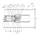
- 1 is a cross-sectional view of a closed state of a gas circuit breaker 100 according to a first embodiment for carrying out the present invention, showing a cross-section of a plane including an axis A described later.
- 2 is a cross-sectional view of the gas circuit breaker 100 seen from a direction parallel to the axis A at the position indicated by the alternate long and short dash line C1 shown in FIG. 1
- FIG. 3 is an axial line at the position indicated by the alternate long and short dash line C2 shown in FIG. It is sectional drawing of the gas circuit breaker 100 seen from the direction parallel to A.
- FIG. Further, FIG.
- FIG. 4 is a cross-sectional view of the gas circuit breaker 100 seen from a direction parallel to the axis A at the position indicated by the alternate long and short dash line C3 shown in FIG. It should be noted that FIG. 1 also serves as a sectional view of a gas circuit breaker 101 according to a second embodiment described later.
- tank 10 is made of metal or the like.
- the inside 10n of the tank 10 is filled with an insulating gas such as SF 6 gas.
- the movable electrode 2 is movable by being supported by the support cylinder 9 on the axis A of the fixed electrode 1 shown by the alternate long and short dash line by a drive mechanism (not shown), and is separable from the fixed electrode 1.
- the axis A is a flow line of the movable electrode 2 when the fixed electrode 1 and the movable electrode 2 are connected and disconnected, and is an extension line of this flow line.
- the fixed electrode 1 is electrically connected to one terminal (not shown) outside the tank 10, and similarly, the movable electrode 2 is electrically connected to the other terminal (not shown) outside the tank 10.
- the movable-side housing 3 that surrounds the movable electrode 2 is configured to interlock with the movable electrode 2, and a nozzle 7 is attached to an end of the movable-side housing 3. Further, the cylinder portion 8 is attached so as to cover the nozzle 7, and the space is closed by the wall surface of the nozzle 7 and the wall surface of the cylinder portion 8 to form a first thermal puffer chamber Tp.
- the movable housing 3 and the cylinder portion 8 surround the axis A and are arranged in series in the direction of the axis A.
- the nozzle 7 is provided with a suction port 7n for sucking the insulating gas into the first thermal puffer chamber Tp, and from the inside of the first thermal puffer chamber Tp between the fixed electrode 1 and the movable electrode 2. And an ejection port 7u for ejecting the insulating gas.
- the movable electrode 2, the movable housing 3, the nozzle 7, the cylinder portion 8, and the first thermal puffer chamber Tp are interlocked with each other to form the movable body portion 21.
- the space closed by the piston 4 whose position is fixed and the wall surface of the movable-side housing 3 forms a mechanical puffer chamber Mp.
- the first thermal puffer chamber Tp and the mechanical puffer chamber Mp are arranged in series in the direction of the axis A.
- the mechanical puffer chamber Mp is configured so that the volume thereof changes according to the operation of the movable body portion 21.
- the space between the movable-side housing 3 and the movable electrode 2 is a first suction port for sucking the insulating gas into the mechanical puffer chamber Mp and ejecting the insulating gas from the mechanical puffer chamber Mp. Responsible for Mnu.
- the cooling cylinder 5 is connected to the fixed electrode 1 and radiates the heat generated in the fixed electrode 1 to the inside 10 n of the tank 10. Further, the fixed-side casing 6 is attached to the cooling cylinder 5, and the fixed-side casing 6 and the movable-side casing 3 are joined together so as to support the connection between the fixed electrode 1 and the movable electrode 2.
- the fixed electrode 1, the cooling cylinder 5, and the fixed-side housing 6 form a fixed body portion 11.
- the movable-side housing 3 is the first movable-side housing described in the claims, and the cylinder portion 8 is the second movable-side housing described in the claims.
- the nozzle 7 has four suction ports 7n, and each suction port 7n has a structure that opens parallel to the axis A.
- the nozzle 7 has four ejection ports 7u, and each ejection port 7u has a structure that opens from the side of the axis A toward the axis A.
- the opening direction of each ejection port 7u and the axis line A are arranged to intersect.
- the first suction port Mnu has a structure that opens parallel to the axis A.
- the suction port 7n and the first suction port Mnu shown in FIG. 1 are arranged to face each other.
- FIG. 5 shows the time dependence of parameters during the operation of the gas circuit breaker 100
- FIG. 5A shows the time dependence of the alternating current flowing between the fixed electrode 1 and the movable electrode 2.
- B is a diagram showing a change in the distance (inter-electrode distance D) between the tip portion of the fixed electrode 1 and the tip portion of the movable electrode 2.
- FIG. 6 is a sectional view of the state of the main part of the gas circuit breaker 100 before the time T0 shown in FIG.
- FIG. 7 is a cross-sectional view of the state of the main part of the gas circuit breaker 100 from time T1 shown in FIG. 5 to time T2.
- FIG. 5 shows the time dependence of parameters during the operation of the gas circuit breaker 100
- FIG. 5A shows the time dependence of the alternating current flowing between the fixed electrode 1 and the movable electrode 2.
- D is a diagram showing a change in the distance (inter-electrode distance D) between the tip portion of the fixed electrode 1 and the tip portion of the
- FIG. 8 is a cross-sectional view of the state of the main part of the gas circuit breaker 100 from time T2 shown in FIG. 5 to T3, and FIG. 9 is a view of the position shown by the one-dot chain line C2 shown in FIG. It is sectional drawing which shows the state of the gas circuit breaker 100 between time T2 and T3.
- FIG. 10 is a temperature distribution diagram of the insulating gas in the direction along the axis A at a certain time between the time T2 and T3, where the vertical axis represents the temperature of the insulating gas and the horizontal axis represents The position along the axis A is shown.
- FIG. 11 is a cross-sectional view of the state of the main part of the gas circuit breaker 100 after time T4 shown in FIG.
- the state before the time T0 before the current interruption of the gas circuit breaker 100 is executed will be described with reference to FIGS. 5 and 6.
- the inter-electrode distance D shown in FIG. 6 indicates the distance between the tip portion of the fixed electrode 1 and the tip portion of the movable electrode 2.
- the inter-electrode distance D is defined as a negative value.
- the inter-electrode distance D approaches a zero value.
- the interelectrode distance D is defined as a positive value.
- the distance Dt is a length component in the direction of the axis A between the tip of the movable electrode 2 and the center of the ejection port 7u of the nozzle 7.
- the fixed electrode 1 and the movable electrode 2 come into contact with each other, so that the alternating current does not go through the arc discharge E, and the fixed electrode 1 and the movable electrode 2 are connected. Flows directly between. Further, when the inter-electrode distance D has a positive value after time T1, the fixed electrode 1 and the movable electrode 2 are separated from each other. Therefore, the current flowing between the fixed electrode 1 and the movable electrode 2 flows through the arc discharge E. Further, since the piston 4 is fixed, the volume of the mechanical puffer chamber Mp decreases in proportion to the amount of change in the interelectrode distance D. That is, the insulating gas inside the mechanical puffer chamber Mp is compressed.
- the gas flow Se branches into a gas flow Smn flowing into the mechanical puffer chamber Mp from the first suction port Mnu and a gas flow Stn flowing into the first thermal puffer chamber Tp from the suction port 7n.
- the heat generation amount of the arc discharge E increases as the absolute value of the current increases.
- the maximum value of the absolute value of the alternating current (the maximum value and the minimum value of the current) is passed between time T1 and T2, so the amount of heat generated by the arc discharge E rapidly increases. Therefore, the pressure of the insulating gas sharply rises, and the gas flow Se also sharply increases.
- the gas flow Smn and the gas flow Stn also rapidly increase, and the gas flow Smn flows into the mechanical puffer chamber Mp from the first suction port Mnu, so that the pressure inside the mechanical puffer chamber Mp sharply rises. Further, since the gas flow Stn flows into the first thermal puffer chamber Tp from the suction port 7n, the pressure inside the first thermal puffer chamber Tp also sharply rises.
- inter-electrode distance D further increases. That is, the volume of the mechanical puffer chamber Mp is compressed in proportion to the amount of change in the inter-electrode distance D.
- the pressure inside the mechanical puffer chamber Mp sharply increased between time T1 and T2, and the volume of the mechanical puffer chamber Mp was compressed, so that the arc discharge E was generated from the first suction port Mnu.
- the gas flow Smu is blown toward it.
- the pressure inside the first thermal puffer chamber Tp also sharply rises between the time T1 and T2, the gas flow Stu flows from the ejection port 7u of the nozzle 7 toward the arc discharge E. Gush out.
- the gas flow Smu is ejected from the first suction port Mnu toward the suction port 7n. It Therefore, the leakage of the insulating gas from the suction port 7n toward the first suction port Mnu is suppressed, and the gas flow Stu ejected from the ejection port 7u of the nozzle 7 is increased. Further, the inter-electrode distance D extends, and the inter-electrode distance D exceeds the distance Dt. That is, the ejection port 7u of the nozzle 7 passes through the tip portion of the fixed electrode 1.
- gas flow Stu is blown toward the arc discharge E from the side in the discharge direction of the arc discharge E while the movable body portion 21 is moving. Further, referring to FIG. 9, gas flow Stu is blown toward arc discharge E from four ejection ports 7u. The gas flow Stu ejected from the four ejection ports 7u is blown from the side of the arc discharge E toward the arc discharge E.
- the temperature of the insulating gas is relatively high from the position of the tip of the movable electrode 2 to the vicinity of the central position of the ejection port 7u, and on the fixed electrode 1 side from the central position of the ejection port 7u. , This temperature drops sharply. This phenomenon is because the gas flow Stu is blown to a specific position of the arc discharge E according to the displacement of the inter-electrode distance D, so that the temperature of the insulating gas becomes low at the position where the gas flow Stu is blown.
- the state of the gas circuit breaker 100 after the time T3 has passed and after T4 will be described.
- the inter-electrode distance D reaches the maximum value Dmax, and the operation of the movable body portion 21 is stopped. That is, the current interruption operation is completed.
- the gas flow Stn branched from the gas flow Se does not pass through the mechanical puffer chamber Mp and flows from the suction port 7n to the first heat source. It is taken into the puffer room Tp. Further, during the period from the time T2 to T3, the gas flow Stn flows in to increase the pressure inside the first heat puffer chamber Tp, and the gas flow Stu is blown from the ejection port 7u toward the arc discharge E.
- the gas flow Smn branched from the gas flow Se flows into the mechanical puffer chamber Mp without passing through the first thermal puffer chamber Tp. Further, between the time T2 and T3, the gas flow Smu is blown toward the arc discharge E due to the compression of the volume of the mechanical puffer chamber Mp by the piston 4.
- the first thermal puffer chamber Tp does not serve as a flow path of the mechanically compressed insulating gas from the mechanical puffer chamber Mp, and the insulation in the mechanical puffer chamber Mp is prevented.
- the rise in the pressure of the characteristic gas is not hindered, and the flow rate of the gas flow Smu flowing from the mechanical puffer chamber Mp to the arc discharge E is not reduced, so that the breaking performance of the gas circuit breaker 100 is not deteriorated. That is, even in the case of the small current interruption duty, the gas flow Stu and the gas flow Smu are turned into the arc discharge E without being hindered from increasing the pressure of the insulating gas in the first thermal puffer chamber Tp and the mechanical puffer chamber Mp. It is possible to efficiently spray and extinguish the arc discharge E.
- the first thermal puffer chamber Tp does not become a flow path of the mechanically compressed insulating gas from the mechanical puffer chamber Mp, and the first thermal puffer chamber Tp does not flow.
- the rise of the insulating gas in the mechanical puffer chamber Mp is not hindered by the outflow of the insulating gas to Tp.
- the first embodiment has high current interruption performance regardless of the magnitude of the current value. Therefore, the gas circuit breaker 100 with a wide corresponding current value range can be provided.
- the suction port 7n and the jet port 7u of the first thermal puffer chamber Tp are arranged at different positions, the insulating gas is sucked in and out in comparison with the case where the insulating gas is sucked and jetted from the same port. There is no need to wait for the time to switch to the gush. That is, compared with the conventional gas circuit breaker, the time from the suction of the insulating gas to the jet of the insulating gas can be shortened. Therefore, if the moving speed of the movable electrode 2 and the time of blowing the gas flow Stu to the arc discharge E are matched, the arc discharge E can be extinguished more rapidly than in the conventional gas circuit breaker.
- first suction port Mnu of the mechanical puffer chamber Mp and the suction port 7n of the nozzle 7 are arranged to face each other, so that the gas flow Smu is ejected from the first suction port Mnu toward the suction port 7n. To be done. Therefore, the leakage of the insulating gas from the suction port 7n toward the first suction port Mnu is suppressed, and the gas flow Stu ejected from the ejection port 7u of the nozzle 7 is increased.
- the first thermal puffer chamber Tp and the mechanical puffer chamber Mp are arranged in series in the direction of the axis A, the first thermal puffer chamber Tp and the mechanical puffer chamber Mp are arranged in the direction perpendicular to the axis A.
- the gas circuit breaker 100 can be downsized as compared with the case where the gas circuit breakers are arranged side by side.
- Embodiment 2 In the first embodiment, it has been described that the ejection ports 7u are arranged so as to intersect with each other in the plane including the opening A and the axis A. When the current forming the arc discharge E becomes small, as in the case of the current value between the time T2 and T3, the cross-sectional area of the arc discharge E is reduced, and the arc discharge E does not pass through the axis A. May occur.
- the opening directions v1 to v4 of the respective jet outlets 7v (collective names of 7v1 to 7v4) and the axis A are not arranged in the same plane.
- the opening directions v1 to v4 of the respective jet outlets 7v and the axis A are arranged in a twisted position.
- FIG. 1 also serves as a cross-sectional view of the gas circuit breaker 100 of the first embodiment and the gas circuit breaker 101 of the second embodiment.
- FIG. 12 is a cross-sectional view of the gas circuit breaker 101 as seen from the direction parallel to the axis A at the position indicated by the alternate long and short dash line C2 in FIG.
- the same symbols and reference numerals as those in FIGS. 1 to 11 are the same as or equivalent to those in the first embodiment, and therefore detailed description will be omitted.
- the current interrupting operation of the gas circuit breaker 101 is the same as that of the gas circuit breaker 100, so detailed description thereof will be omitted.
- the four ejection ports 7v1 to 7v4 are opened from the side of the axis A. Further, the opening direction v1 of the ejection port 7v1 is not arranged in the same plane as the axis A. That is, the opening direction v1 of the ejection port 7v1 and the axis A are arranged in a twisted position. Similarly, the opening direction v2 of the ejection port 7v2 and the axis A are arranged in a twisted position, the opening direction v3 of the ejection port 7v3 and the axis A are arranged in a twisted position, and the opening direction v4 of the ejection port 7v4 is arranged.
- the axis A are arranged in a twisted position.
- the opening direction v1 of the ejection port 7v1, the opening direction v2 of the ejection port 7v2, the opening direction v3 of the ejection port 7v3, and the opening direction v4 of the ejection port 7v4 are projected onto a plane having the axis A of the fixed electrode 1 as a normal line. Then, the opening directions v1 to v4 are arranged at positions deviated from the axis A of the fixed electrode 1.
- the second embodiment has high current interruption performance regardless of the magnitude of the current value, as in the first embodiment. Therefore, the gas circuit breaker 101 with a wide corresponding current value range can be provided.
- FIG. 13 is a sectional view of gas circuit breaker 102 according to the third embodiment of the present invention.
- the present embodiment is different from the first embodiment in that a second thermal puffer chamber Tp2 is further provided.
- the same symbols and reference numerals as in FIGS. 1 to 12 in the drawings are the same as or equivalent to those in the first embodiment, and therefore detailed description thereof will be omitted.
- a partition wall 12 is formed on the inner wall surface of the movable-side housing 3 to partition the internal space of the movable-side housing 3 into a mechanical puffer chamber Mp and a second thermal puffer chamber Tp2.
- a space surrounded by the partition wall 12, the movable-side housing 3, the piston 4, and the movable electrode 2 is a mechanical puffer chamber Mp.
- the space surrounded by the partition wall 12, the movable-side housing 3, and the movable electrode 2 is the second thermal puffer chamber Tp2.
- the mechanical puffer chamber Mp, the first thermal puffer chamber Tp, and the second thermal puffer chamber Tp2 are arranged in series in the direction of the axis A.
- the mechanical puffer chamber Mp is arranged in the direction of the axis A on the opposite side of the first thermal puffer chamber Tp with the second thermal puffer chamber Tp2 interposed therebetween. That is, the second thermal puffer chamber Tp2 is arranged between the mechanical puffer chamber Mp and the first thermal puffer chamber Tp in the direction of the axis A.
- the partition wall 12 is a disk-shaped portion having a through hole formed in the center.
- the movable electrode 2 is passed through the through hole of the partition wall 12.
- the diameter of the through hole of the partition wall 12 is larger than the outer diameter of the movable electrode 2. Therefore, a gap is formed between the partition wall 12 and the movable electrode 2.
- This gap that is, a portion of the through hole of the partition wall 12 other than the portion through which the movable electrode 2 passes serves as a first suction port Mnu that connects the mechanical puffer chamber Mp and the second thermal puffer chamber Tp2.
- the first suction port Mnu serves as a flow path for the insulating gas.
- the insulating gas flows from the second thermal puffer chamber Tp2 through the first suction port Mnu into the mechanical puffer chamber Mp.
- the insulating gas flows from the mechanical puffer chamber Mp through the first suction port Mnu into the second thermal puffer chamber Tp2.
- An annular check valve 13 is arranged on the outer peripheral surface of the movable electrode 2.
- the movable electrode 2 is passed through the through hole formed at the center of the check valve 13.
- the check valve 13 is arranged in the second thermal puffer chamber Tp2.
- the check valve 13 is movable in the direction of the axis A relative to the movable body portion 21.
- the check valve 13 closes the first suction port Mnu and opens the first suction port Mnu.
- the state in which the check valve 13 closes the first suction port Mnu is referred to as a “closed state of the first suction port Mnu”, and the check valve 13 opens the first suction port Mnu.
- the state is referred to as the “open state of the first suction port Mnu”.
- a second suction port Mnv is formed in the movable-side housing 3 on the side opposite to the partition wall 12 with the second thermal puffer chamber Tp2 interposed therebetween.
- the second suction port Mnv serves as a flow path for the insulating gas.
- the insulating gas flows into the second thermal puffer chamber Tp2 through the second suction port Mnv.
- the insulating gas flows out of the second thermal puffer chamber Tp2 through the second suction port Mnv.
- the second suction port Mnv is formed between the movable electrode 2 and a part of the nozzle 7 that comes into contact with the inner wall surface of the movable-side housing 3. It may be formed between the wall surface and the movable electrode 2.
- the first thermal puffer chamber Tp is arranged at a position different from the flow path of the insulating gas flowing from the mechanical puffer chamber Mp to the arc discharge E.
- the operation of the gas circuit breaker 102 when a large current is cut off will be described.
- the thermal energy of the arc discharge E that is generated is high, so the pressure of the insulating gas in the second thermal puffer chamber Tp2 is sufficiently increased.
- the check valve 13 moves toward the mechanical puffer chamber Mp. The check valve 13 contacts the surface of the partition wall 12 that faces the second thermal puffer chamber Tp2 and closes the first suction port Mnu.
- the insulating gas in the closed state of the first suction port Mnu, the insulating gas is discharged from the periphery of the arc discharge E to the second position between the time T1 and the time T2 shown in FIG.
- the suction port Mnv and into the second thermal puffer chamber Tp2 and from around the arc discharge E through the suction port 7n into the first thermal puffer chamber Tp. Therefore, the pressure of the insulating gas in the second thermal puffer chamber Tp2 and the first thermal puffer chamber Tp increases.
- the insulating gas passes from the inside of the second thermal puffer chamber Tp2 through the second suction port Mnv until time T3 after the time T2 shown in FIG.
- the operation of the gas circuit breaker 102 when the small current is cut off will be described.
- the thermal energy of the arc discharge E that is generated is low, so the pressure of the insulating gas in the second thermal puffer chamber Tp2 does not become sufficiently high.
- the pressure of the insulating gas in the mechanical puffer chamber Mp is higher than the pressure of the insulating gas in the second thermal puffer chamber Tp2. Therefore, the check valve 13 moves in a direction away from the mechanical puffer chamber Mp.
- the check valve 13 separates from the partition wall 12 and opens the first suction port Mnu.
- the insulating gas in the open state of the first suction port Mnu is discharged from the periphery of the arc discharge E to the second position between the time T1 and the time T2 shown in FIG.
- the suction port Mnv and into the second thermal puffer chamber Tp2 and from around the arc discharge E through the suction port 7n into the first thermal puffer chamber Tp. Therefore, the pressure of the insulating gas in the second thermal puffer chamber Tp2 and the first thermal puffer chamber Tp increases.
- the insulating gas in the mechanical puffer chamber Mp passes through the first suction port Mnu between time T1 and time T2 shown in FIG.
- the insulating gas passes through the first suction port Mnu from the inside of the mechanical puffer chamber Mp to the second time between the time T2 and the time T3 shown in FIG. After flowing into the heat puffer chamber Tp2 of No. 1, it is sprayed toward the arc discharge E through the second suction port Mnv. That is, the second thermal puffer chamber Tp2 serves as a flow path of the insulating gas flowing from the mechanical puffer chamber Mp to the arc discharge E.
- the insulating gas passes from the inside of the first thermal puffer chamber Tp through the jet port 7u until the time T3 after the time T2 shown in FIG. It is blown toward the arc discharge E.
- the arc discharge E is extinguished by blowing the insulating gas toward the arc discharge E.
- the volume of the thermal puffer chamber is determined based on the large current interruption performance required for the gas circuit breaker 102.
- two thermal puffer chambers that is, the first thermal puffer chamber Tp and the second thermal puffer chamber Tp2 are provided, so that it is necessary to realize the large current interruption performance required for the gas circuit breaker 102.
- the volume of such a heat puffer chamber is divided into a first heat puffer chamber Tp and a second heat puffer chamber Tp2. That is, the volume of the second thermal puffer chamber Tp2 can be reduced by the volume of the first thermal puffer chamber Tp.
- the gas circuit breaker 102 can be downsized as compared with the case where the thermal puffer chamber is provided only in the flow path of the insulating gas from the mechanical puffer chamber Mp toward the arc discharge E.
- the small current interruption performance of the gas circuit breaker 102 is determined by the compressibility of the insulating gas in the mechanical puffer chamber Mp and the second thermal puffer chamber Tp2. Specifically, as the compressibility of the insulating gas in the mechanical puffer chamber Mp and the second thermal puffer chamber Tp2 is higher, the small current breaking performance of the gas circuit breaker 102 is improved.
- the second thermal puffer chamber Tp2 serves as a flow path of the insulating gas flowing from the mechanical puffer chamber Mp to the arc discharge E
- the compressibility of the insulating gas in the second heat puffer chamber Tp2 becomes low. As a result, the rise of the pressure of the insulating gas in the mechanical puffer chamber Mp is hindered when the small current is cut off.
- the volume of the second thermal puffer chamber Tp2 can be reduced by the volume of the first thermal puffer chamber Tp, the flow path of the insulating gas from the mechanical puffer chamber Mp to the arc discharge E is reduced.
- the compressibility of the insulating gas in the second thermal puffer chamber Tp2 is higher than that in the case where the thermal puffer chamber is provided only in the second thermal puffer chamber. Therefore, the small current interruption performance of the gas circuit breaker 102 can be improved.
- the nozzle 7 may be made of an ablative material.
- the heat of the gas flow Stn evaporates the ablatable material.
- the pressure inside the first thermal puffer chamber Tp rises, and the pressure of the gas flow Stu ejected from the ejection port 7u rises. That is, a high-pressure gas flow Stu can be blown by the arc discharge E to efficiently extinguish the arc discharge E.
- the first thermal puffer chamber Tp may be formed of an ablatable material, and further, the ablatable material may be disposed inside the first thermal puffer chamber Tp. Even in such a case, the pressure inside the first thermal puffer chamber Tp rises, and the pressure of the gas flow Stu jetted from the jet outlet 7u rises.
- the ablative material include polytetrafluoroethylene (PTFE) and perfluoroalkyl vinyl ether copolymer (PFA). Further, at least one compound selected from the group consisting of perfluoroether polymers, fluoroelastomers, and 4-vinyloxy-1-butene (BVE) cyclized polymers can be used as the ablative material. .
- the nozzle 7 has four suction ports 7n and four ejection ports 7u, but the present invention limits the number of the suction ports 7n and the ejection ports 7u. However, the numbers of the suction ports 7n and the ejection ports 7u are appropriately determined when designing the gas circuit breakers 100 to 102.
- the ejection ports 7u are arranged so as to intersect with each other in the plane including the opening direction and the axis A.
- the ejection directions and the axis lines of the respective ejection ports 7v are arranged.
- A is arranged in a twisted position, the present invention is not limited to the opening direction of the ejection ports (7u, 7v).
- the respective embodiments can be freely combined within the scope of the invention, and the respective embodiments can be appropriately changed or omitted.
- the nozzle 7 may be provided with both the ejection port 7u opening from the side of the axis A toward the axis A and the ejection port 7v opening at a twisted position.
Landscapes
- Circuit Breakers (AREA)
Abstract
ガス遮断器(100)は、固定電極(1)と、固定電極(1)の軸線上を可動し固定電極(1)と接離可能な可動電極(2)と、可動電極(2)と連動する可動側筐体(3)と、可動側筐体(3)とで機械パッファ室(Mp)を形成するピストン(4)と、可動電極(2)と連動し軸線の方向に可動側筐体(3)と直列に位置するシリンダー部(8)と、シリンダー部(8)とで第1の熱パッファ室(Tp)を形成するノズル(7)とを備える。可動側筐体(3)には、絶縁性ガスを機械パッファ室(Mp)内に吸入し、かつ、絶縁性ガスを機械パッファ室(Mp)内から噴出するための第1の吸出口(Mnu)が形成される。ノズル(7)には、絶縁性ガスを第1の熱パッファ室(Tp)内に吸入するための吸入口(7n)と、第1の熱パッファ室(Tp)内から固定電極(1)と可動電極(2)との間に向けて絶縁性ガスを噴出するための噴出口(7u)とが形成される。
Description
この発明は、開閉動作を行うことにより電力の供給および遮断を実行するガス遮断器に関するものである。
従来のガス遮断器は、機械的圧縮室(機械パッファ室)と熱的昇圧室(熱パッファ室)とを備える。機械パッファ室は、この機械パッファ室内で絶縁性ガスを機械的に圧縮し、この圧縮された絶縁性ガスを電流遮断時に接触子間に生じるアーク放電へ吹き付ける機構を備える。なお、以下の説明では、アーク放電が生じている領域を、単にアーク放電ともいう。熱パッファ室は、アーク放電の熱エネルギーにより絶縁性ガスの圧力を高め、この高圧化された絶縁性ガスをアーク放電へ吹き付ける役割を担う。
電流遮断時にアーク放電が発生する場合、機械パッファ室と熱パッファ室とから吹き付けられる絶縁性ガスによって、アーク放電で生じるイオン化されたガスを除去し、アーク放電を消弧させて電流遮断が完了する(例えば、特許文献1)。
電流遮断時にアーク放電が発生する場合、機械パッファ室と熱パッファ室とから吹き付けられる絶縁性ガスによって、アーク放電で生じるイオン化されたガスを除去し、アーク放電を消弧させて電流遮断が完了する(例えば、特許文献1)。
このような従来のガス遮断器の電流遮断性能は、アーク放電へ絶縁性ガスを吹き付けるときの絶縁性ガスの圧力に大きく依存する。すなわち、機械パッファ室と熱パッファ室とで、絶縁性ガスの圧力を高圧化することにより、電流遮断性能を確保する必要がある。
しかしながら、ガス遮断器に比較的小電流が流れるときの電流遮断(小電流遮断責務)では、電流遮断時に発生するアーク放電の熱エネルギーが低い。そのため、熱パッファ室における絶縁性ガスの圧力が十分に高くならないことがある。
さらに、従来のガス遮断器では、熱パッファ室が機械パッファ室からの絶縁性ガスの流路に配置されているために、小電流遮断責務では機械パッファ室における絶縁性ガスの圧力の上昇が阻害されることがある。また、機械パッファ室からアーク放電へ流れるガスの流速が減速し、ガス遮断器の遮断性能を低下させる要因になる可能性もある。
すなわち、小電流遮断責務においては、従来のガス遮断器は電流遮断性能が低下する問題があった。
しかしながら、ガス遮断器に比較的小電流が流れるときの電流遮断(小電流遮断責務)では、電流遮断時に発生するアーク放電の熱エネルギーが低い。そのため、熱パッファ室における絶縁性ガスの圧力が十分に高くならないことがある。
さらに、従来のガス遮断器では、熱パッファ室が機械パッファ室からの絶縁性ガスの流路に配置されているために、小電流遮断責務では機械パッファ室における絶縁性ガスの圧力の上昇が阻害されることがある。また、機械パッファ室からアーク放電へ流れるガスの流速が減速し、ガス遮断器の遮断性能を低下させる要因になる可能性もある。
すなわち、小電流遮断責務においては、従来のガス遮断器は電流遮断性能が低下する問題があった。
この発明は、これらの課題を解決するためになされたものであり、この発明の目的は、小電流遮断責務においても、電流遮断性能の低下を抑制できるガス遮断器を提供することである。
この発明に係るガス遮断器は、絶縁性ガスが充填されるタンク内に、導電性の固定電極と、この固定電極の軸線上を可動しこの固定電極と接離可能な可動電極と、この可動電極と連動しこの軸線を包囲する第1の可動側筐体と、第1の可動側筐体とで機械パッファ室を形成するピストンと、この可動電極と連動しこの軸線の方向に第1の可動側筐体と直列に位置する第2の可動側筐体と、第2の可動側筐体とで第1の熱パッファ室を形成するノズルとを備える。
さらに、この第1の可動側筐体には、絶縁性ガスを機械パッファ室内に吸入し、かつ、絶縁性ガスを機械パッファ室内から噴出するための第1の吸出口が形成され、このノズルには、絶縁性ガスを第1の熱パッファ室内に吸入するための吸入口と、第1の熱パッファ室内から固定電極と可動電極との間に向けて絶縁性ガスを噴出するための噴出口とが形成される。
さらに、この第1の可動側筐体には、絶縁性ガスを機械パッファ室内に吸入し、かつ、絶縁性ガスを機械パッファ室内から噴出するための第1の吸出口が形成され、このノズルには、絶縁性ガスを第1の熱パッファ室内に吸入するための吸入口と、第1の熱パッファ室内から固定電極と可動電極との間に向けて絶縁性ガスを噴出するための噴出口とが形成される。
この発明によるガス遮断器は、小電流遮断責務においても電流遮断性能の低下を抑制でき、高い電流遮断性能を備える。
以下に、本発明の実施の形態にかかるガス遮断器を図面に基づいて詳細に説明する。なお、この実施の形態によりこの発明が限定されるものではない。
実施の形態1.
図1~図11は、この発明を実施するための実施の形態1を示すものである。
図1~図4を参照して、この発明を実施するための実施の形態1に係るガス遮断器100の構造を説明し、図5~図11を参照して、ガス遮断器100の電流遮断動作を説明する。
図1~図11は、この発明を実施するための実施の形態1を示すものである。
図1~図4を参照して、この発明を実施するための実施の形態1に係るガス遮断器100の構造を説明し、図5~図11を参照して、ガス遮断器100の電流遮断動作を説明する。
はじめに、図1~図4を参照して、実施の形態1に係るガス遮断器100の構造を説明する。
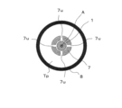
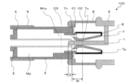
図1は、この発明を実施するための実施の形態1に係るガス遮断器100の閉状態の断面図であり、後述する軸線Aを含む面の断面を示す。図2は、図1に示す一点鎖線C1に示す位置における軸線Aに平行な方向から見たガス遮断器100の断面図であり、図3は、図1に示す一点鎖線C2に示す位置における軸線Aに平行な方向から見たガス遮断器100の断面図である。さらに、図4は、図1に示す一点鎖線C3に示す位置における軸線Aに平行な方向から見たガス遮断器100の断面図である。
なお、図1は、後述する実施の形態2に係るガス遮断器101の断面図を兼ねる。
図1は、この発明を実施するための実施の形態1に係るガス遮断器100の閉状態の断面図であり、後述する軸線Aを含む面の断面を示す。図2は、図1に示す一点鎖線C1に示す位置における軸線Aに平行な方向から見たガス遮断器100の断面図であり、図3は、図1に示す一点鎖線C2に示す位置における軸線Aに平行な方向から見たガス遮断器100の断面図である。さらに、図4は、図1に示す一点鎖線C3に示す位置における軸線Aに平行な方向から見たガス遮断器100の断面図である。
なお、図1は、後述する実施の形態2に係るガス遮断器101の断面図を兼ねる。
図1を参照して、タンク10は、金属などで構成される。タンク10の内部10nには、SF6ガスなどの絶縁性ガスが充填される。可動電極2は、図示しない駆動機構により、一点鎖線に示す固定電極1の軸線A上を支持筒9に支持され可動し、固定電極1と切離可能に構成される。言い換えると、軸線Aは、固定電極1と可動電極2とが接続および切り離しをするときの可動電極2の動線であり、この動線の延長線である。
さらに、固定電極1は、タンク10の外部の図示しない一方の端子に電気的に接続され、同様に可動電極2は、タンク10の外部の図示しない他方の端子に電気的に接続される。
可動電極2を包囲する可動側筐体3は、可動電極2と連動するように構成され、可動側筐体3の端部には、ノズル7が取り付けられる。さらに、ノズル7を覆うようにシリンダー部8が取り付けられ、ノズル7の壁面とシリンダー部8の壁面とで閉じられて空間は、第1の熱パッファ室Tpを形成する。言い換えると、可動側筐体3とシリンダー部8とは、軸線Aを包囲し、軸線Aの方向に直列に配置される。
さらに、ノズル7は、絶縁性ガスを第1の熱パッファ室Tp内に吸入するための吸入口7nと、第1の熱パッファ室Tp内から固定電極1と可動電極2との間に向けて絶縁性ガスを噴出するための噴出口7uとを有する。可動電極2、可動側筐体3、ノズル7、シリンダー部8、および第1の熱パッファ室Tpは、連動し、可動体部21を構成する。
さらに、固定電極1は、タンク10の外部の図示しない一方の端子に電気的に接続され、同様に可動電極2は、タンク10の外部の図示しない他方の端子に電気的に接続される。
可動電極2を包囲する可動側筐体3は、可動電極2と連動するように構成され、可動側筐体3の端部には、ノズル7が取り付けられる。さらに、ノズル7を覆うようにシリンダー部8が取り付けられ、ノズル7の壁面とシリンダー部8の壁面とで閉じられて空間は、第1の熱パッファ室Tpを形成する。言い換えると、可動側筐体3とシリンダー部8とは、軸線Aを包囲し、軸線Aの方向に直列に配置される。
さらに、ノズル7は、絶縁性ガスを第1の熱パッファ室Tp内に吸入するための吸入口7nと、第1の熱パッファ室Tp内から固定電極1と可動電極2との間に向けて絶縁性ガスを噴出するための噴出口7uとを有する。可動電極2、可動側筐体3、ノズル7、シリンダー部8、および第1の熱パッファ室Tpは、連動し、可動体部21を構成する。
また、位置が固定されたピストン4と可動側筐体3の壁面とで閉じられて空間は、機械パッファ室Mpを形成する。言い換えると、第1の熱パッファ室Tpと機械パッファ室Mpとは、軸線Aの方向に直列に配置される。なお、詳細は後述するが、機械パッファ室Mpは、可動体部21が動作するのに応じ、容積が変化するように構成される。
さらに、可動側筐体3と可動電極2との間の空間は、絶縁性ガスを機械パッファ室Mp内に吸入し、かつ絶縁性ガスを機械パッファ室Mpから噴出するための第1の吸出口Mnuを担う。
さらに、可動側筐体3と可動電極2との間の空間は、絶縁性ガスを機械パッファ室Mp内に吸入し、かつ絶縁性ガスを機械パッファ室Mpから噴出するための第1の吸出口Mnuを担う。
冷却筒5は固定電極1に接続され、固定電極1に発生する熱をタンク10の内部10nに放熱する。さらに、固定側筐体6は冷却筒5に取り付けられ、固定電極1と可動電極2との接続を支持するように、固定側筐体6と可動側筐体3とは篏合する。
固定電極1、冷却筒5、および固定側筐体6は、固定体部11を構成する。
固定電極1、冷却筒5、および固定側筐体6は、固定体部11を構成する。
なお、可動側筐体3は、請求の範囲に記す第1の可動側筐体であり、シリンダー部8は、請求の範囲に記す第2の可動側筐体である。
さらに、図2を参照して、ノズル7は4個の吸入口7nを有し、各々の吸入口7nは、軸線Aと平行に開口する構造を備える。
つぎに、図3を参照して、ノズル7は4個の噴出口7uを有し、各々の噴出口7uは、軸線Aの側方から軸線Aに向かって開口する構造を備える。言い換えると、各々の噴出口7uの開口方向と軸線Aとを含む平面内で、各々の噴出口7uの開口方向と軸線Aとが交差するように配置される。
さらに、図4を参照して、第1の吸出口Mnuは軸線Aと平行に開口する構造を備える。さらに、図1に示す吸入口7nと第1の吸出口Mnuとは、対向して配置される。
つぎに、図3を参照して、ノズル7は4個の噴出口7uを有し、各々の噴出口7uは、軸線Aの側方から軸線Aに向かって開口する構造を備える。言い換えると、各々の噴出口7uの開口方向と軸線Aとを含む平面内で、各々の噴出口7uの開口方向と軸線Aとが交差するように配置される。
さらに、図4を参照して、第1の吸出口Mnuは軸線Aと平行に開口する構造を備える。さらに、図1に示す吸入口7nと第1の吸出口Mnuとは、対向して配置される。
つぎに、図5~図11を参照して、ガス遮断器100の電流遮断動作について説明する。
図5は、ガス遮断器100の動作時のパラメータの時間依存性を示し、図5(a)は、固定電極1と可動電極2との間を流れる交流電流の時間依存性を示し、図5(b)は、固定電極1の先端部分と可動電極2との先端部分の距離(電極間距離D)の変化を示す図である。
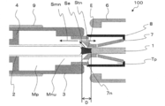
図6は、図5に示す時刻T0以前のガス遮断器100の主要部分の状態の断面図である。図7は、図5に示す時刻T1を経過しT2までの間のガス遮断器100の主要部分の状態の断面図である。
図8は、図5に示す時刻T2を経過しT3までの間のガス遮断器100の主要部分の状態の断面図であり、図9は、図3と同様に示す一点鎖線C2に示す位置の時刻T2を経過しT3までの間におけるガス遮断器100の状態を示す断面図である。さらに、図10は、時刻T2を経過しT3までの間の一定時刻における軸線Aに沿った方向の絶縁性ガスの温度分布図であり、縦軸は絶縁性ガスの温度であり、横軸は軸線Aに沿った位置を示す。
図11は、図5に示す時刻T4以降の間のガス遮断器100の主要部分の状態の断面図である。
図5は、ガス遮断器100の動作時のパラメータの時間依存性を示し、図5(a)は、固定電極1と可動電極2との間を流れる交流電流の時間依存性を示し、図5(b)は、固定電極1の先端部分と可動電極2との先端部分の距離(電極間距離D)の変化を示す図である。
図6は、図5に示す時刻T0以前のガス遮断器100の主要部分の状態の断面図である。図7は、図5に示す時刻T1を経過しT2までの間のガス遮断器100の主要部分の状態の断面図である。
図8は、図5に示す時刻T2を経過しT3までの間のガス遮断器100の主要部分の状態の断面図であり、図9は、図3と同様に示す一点鎖線C2に示す位置の時刻T2を経過しT3までの間におけるガス遮断器100の状態を示す断面図である。さらに、図10は、時刻T2を経過しT3までの間の一定時刻における軸線Aに沿った方向の絶縁性ガスの温度分布図であり、縦軸は絶縁性ガスの温度であり、横軸は軸線Aに沿った位置を示す。
図11は、図5に示す時刻T4以降の間のガス遮断器100の主要部分の状態の断面図である。
図5および図6を参照して、ガス遮断器100の電流遮断を実行する前の時刻T0以前の状態を説明する。
時刻T0以前では、固定電極1と可動電極2との間に交流電流が定常的に流れている。
図6に示す電極間距離Dは、固定電極1の先端部分と可動電極2との先端部分の距離を示す。また、固定電極1の先端部分と可動電極2との先端部分が篏合し接触する状態の場合、電極間距離Dは負の値と定義する。
さらに、ガス遮断器100の電流遮断動作が進行(可動体部21が紙面左側に移動)すると、電極間距離Dは、ゼロ値に近づく。さらに、ガス遮断器100の電流遮断動作が進行し、固定電極1の先端部分と可動電極2との先端部分が接触しない状態の場合、電極間距離Dは、正の値と定義する。
また、距離Dtは、可動電極2の先端部分とノズル7の噴出口7uの中心との軸線A方向の長さ成分である。
時刻T0以前では、固定電極1と可動電極2との間に交流電流が定常的に流れている。
図6に示す電極間距離Dは、固定電極1の先端部分と可動電極2との先端部分の距離を示す。また、固定電極1の先端部分と可動電極2との先端部分が篏合し接触する状態の場合、電極間距離Dは負の値と定義する。
さらに、ガス遮断器100の電流遮断動作が進行(可動体部21が紙面左側に移動)すると、電極間距離Dは、ゼロ値に近づく。さらに、ガス遮断器100の電流遮断動作が進行し、固定電極1の先端部分と可動電極2との先端部分が接触しない状態の場合、電極間距離Dは、正の値と定義する。
また、距離Dtは、可動電極2の先端部分とノズル7の噴出口7uの中心との軸線A方向の長さ成分である。
時刻T1以前の電極間距離Dが負の値である場合、固定電極1と可動電極2とは接触することにより、交流電流はアーク放電Eを介すことなく、固定電極1と可動電極2との間を直接流れる。
また、時刻T1以降に、電極間距離Dは正の値となる場合、固定電極1と可動電極2との間は乖離する。そのため、固定電極1と可動電極2との間に流れる電流は、アーク放電Eを介して流れる。
また、ピストン4は固定されているので、電極間距離Dの変化量に比例して機械パッファ室Mpの容積は減少する。すなわち、機械パッファ室Mp内部の絶縁性ガスは、圧縮される。
また、時刻T1以降に、電極間距離Dは正の値となる場合、固定電極1と可動電極2との間は乖離する。そのため、固定電極1と可動電極2との間に流れる電流は、アーク放電Eを介して流れる。
また、ピストン4は固定されているので、電極間距離Dの変化量に比例して機械パッファ室Mpの容積は減少する。すなわち、機械パッファ室Mp内部の絶縁性ガスは、圧縮される。
つぎに、図5および図7を参照して、時刻T0で電流遮断動作を開始後、可動体部21は紙面左側に移動し、電極間距離Dがゼロ値になる時刻T1を経過し、時刻T2を経過しT3までの間のガス遮断器100の状態を説明する。
なお、固定電極1と可動電極2との間に、高熱を伴うアーク放電Eが発生する場合を説明する。また、アーク放電Eは、軸線Aに沿った方向に、放電の方向を有する。
さらに、この高熱によりアーク放電Eの近傍の絶縁性ガスが加熱されて、絶縁性ガスの圧力が上昇する。そのため、アーク放電Eの近傍から可動側筐体3の方向へ流れる絶縁性ガスのガス流Seを生じる。
なお、固定電極1と可動電極2との間に、高熱を伴うアーク放電Eが発生する場合を説明する。また、アーク放電Eは、軸線Aに沿った方向に、放電の方向を有する。
さらに、この高熱によりアーク放電Eの近傍の絶縁性ガスが加熱されて、絶縁性ガスの圧力が上昇する。そのため、アーク放電Eの近傍から可動側筐体3の方向へ流れる絶縁性ガスのガス流Seを生じる。
さらに、ガス流Seは、第1の吸出口Mnuから機械パッファ室Mpへ流入するガス流Smnと、吸入口7nから第1の熱パッファ室Tpに流入するガス流Stnに分岐する。
また、アーク放電Eの発熱量は、電流の絶対値が高いほど増加する。時刻T1を経過しT2までの間に、交流電流の絶対値の最大値(電流の最大値および最小値)を経るので、アーク放電Eが発生する熱量は、急激に増加する。そのため、絶縁性ガスの圧力が急激に上昇し、ガス流Seも急激に増加する。
同様に、ガス流Smnおよびガス流Stnも急激に増加し、第1の吸出口Mnuからガス流Smnが機械パッファ室Mpに流入するので、機械パッファ室Mpの内部の圧力が急激に上昇する。また、吸入口7nからガス流Stnが第1の熱パッファ室Tpに流入するので、第1の熱パッファ室Tpの内部の圧力も急激に上昇する。
また、アーク放電Eの発熱量は、電流の絶対値が高いほど増加する。時刻T1を経過しT2までの間に、交流電流の絶対値の最大値(電流の最大値および最小値)を経るので、アーク放電Eが発生する熱量は、急激に増加する。そのため、絶縁性ガスの圧力が急激に上昇し、ガス流Seも急激に増加する。
同様に、ガス流Smnおよびガス流Stnも急激に増加し、第1の吸出口Mnuからガス流Smnが機械パッファ室Mpに流入するので、機械パッファ室Mpの内部の圧力が急激に上昇する。また、吸入口7nからガス流Stnが第1の熱パッファ室Tpに流入するので、第1の熱パッファ室Tpの内部の圧力も急激に上昇する。
さらに、図5、図8~図10を参照して、時刻T2を経過しT3までの間のガス遮断器100の状態を説明する。
図5および図8を参照して、ガス遮断器100の電流遮断動作が進行すると、さらに電極間距離Dは広がる。すなわち、電極間距離Dの変化量に比例して、機械パッファ室Mpの容積が圧縮される。
時刻T1を経過しT2までの間に機械パッファ室Mpの内部の圧力も急激に高まったこと、および機械パッファ室Mpの容積が圧縮されることにより、第1の吸出口Mnuからアーク放電Eに向かって、ガス流Smuが吹きつけられる。
同様に、時刻T1を経過しT2までの間に第1の熱パッファ室Tpの内部の圧力も急激に高まったことにより、ノズル7の噴出口7uからアーク放電Eに向かって、ガス流Stuが噴出する。
図5および図8を参照して、ガス遮断器100の電流遮断動作が進行すると、さらに電極間距離Dは広がる。すなわち、電極間距離Dの変化量に比例して、機械パッファ室Mpの容積が圧縮される。
時刻T1を経過しT2までの間に機械パッファ室Mpの内部の圧力も急激に高まったこと、および機械パッファ室Mpの容積が圧縮されることにより、第1の吸出口Mnuからアーク放電Eに向かって、ガス流Smuが吹きつけられる。
同様に、時刻T1を経過しT2までの間に第1の熱パッファ室Tpの内部の圧力も急激に高まったことにより、ノズル7の噴出口7uからアーク放電Eに向かって、ガス流Stuが噴出する。
また、機械パッファ室Mpの第1の吸出口Mnuとノズル7の吸入口7nとは、対向し配置されるので、第1の吸出口Mnuからガス流Smuが、吸入口7nに向かって噴出される。そのため、吸入口7nから第1の吸出口Mnu方向への絶縁性ガスの漏れが抑制され、ノズル7の噴出口7uから噴出するガス流Stuを増量する効果を得る。
さらに、電極間距離Dが伸びて、電極間距離Dは距離Dtを上回る。すなわち、ノズル7の噴出口7uが、固定電極1の先端部分を通過する。このため、可動体部21の移動中に、ガス流Stuは、アーク放電Eの放電方向の側方からアーク放電Eに向かって吹きつける。
さらに、図9を参照して、4個の噴出口7uからアーク放電Eに向かって、ガス流Stuが吹き付けられる。4個の噴出口7uから噴出するガス流Stuは、アーク放電Eの側方からアーク放電Eに向かって吹き付けられる。
さらに、電極間距離Dが伸びて、電極間距離Dは距離Dtを上回る。すなわち、ノズル7の噴出口7uが、固定電極1の先端部分を通過する。このため、可動体部21の移動中に、ガス流Stuは、アーク放電Eの放電方向の側方からアーク放電Eに向かって吹きつける。
さらに、図9を参照して、4個の噴出口7uからアーク放電Eに向かって、ガス流Stuが吹き付けられる。4個の噴出口7uから噴出するガス流Stuは、アーク放電Eの側方からアーク放電Eに向かって吹き付けられる。
図10を参照して、可動電極2の先端部分位置から噴出口7uの中心位置近傍までは、絶縁性ガスの温度が比較的高温であり、噴出口7uの中心位置より固定電極1の側では、急激にこの温度は低くなる。この現象は、電極間距離Dの変位に応じてガス流Stuが、アーク放電Eの特定の位置に吹き付けられるので、ガス流Stuが吹き付けられた位置における絶縁性ガスの温度が低くなることによる。
よって、ガス流Smuとガス流Stuとを、アーク放電Eへ吹きつけることにより、アーク放電Eにより生じたイオンおよび電子が消散し、アーク放電Eが急激に減衰し、交流電流がゼロになる時刻T3において、アーク放電Eは消弧する。
さらに、図5および図11を参照して、時刻T3を経過しT4以降のガス遮断器100の状態を説明する。
時刻T4で、電極間距離Dが、最大値Dmaxに達し可動体部21の動作が停止する。すなわち、電流遮断動作を完了する。
時刻T4で、電極間距離Dが、最大値Dmaxに達し可動体部21の動作が停止する。すなわち、電流遮断動作を完了する。
すなわち、本実施の形態1によれば、時刻T1を経過しT2までの間に、ガス流Seから分岐したガス流Stnが、機械パッファ室Mpを介すことなく吸入口7nから第1の熱パッファ室Tpに取り込まれる。さらに、時刻T2を経過しT3までの間に、ガス流Stnの流入により、第1の熱パッファ室Tpの内部の圧力を上げ、噴出口7uからアーク放電Eに向かって、ガス流Stuが吹き付けられる。
一方、時刻T1を経過しT2までの間に、ガス流Seから分岐したガス流Smnが、第1の熱パッファ室Tpを介すことなく、機械パッファ室Mpに流入する。さらに、時刻T2を経過しT3までの間に、ピストン4による機械パッファ室Mpの容積の圧縮により、アーク放電Eに向かって、ガス流Smuが吹き付けられる。
一方、時刻T1を経過しT2までの間に、ガス流Seから分岐したガス流Smnが、第1の熱パッファ室Tpを介すことなく、機械パッファ室Mpに流入する。さらに、時刻T2を経過しT3までの間に、ピストン4による機械パッファ室Mpの容積の圧縮により、アーク放電Eに向かって、ガス流Smuが吹き付けられる。
すなわち、時刻T2を経過しT3までの間に、第1の熱パッファ室Tpからのガス流Stuと機械パッファ室Mpからのガス流Smuが、アーク放電Eに向かって吹き付けられ、時刻T4で可動体部21の動作が停止するまでに、アーク放電Eは消弧されて電流遮断動作を完了する。
よって、従来のガス遮断器のように、第1の熱パッファ室Tpが、機械パッファ室Mpからの機械的に圧縮される絶縁性ガスの流路になることはなく、機械パッファ室Mpにおける絶縁性ガスの圧力の上昇が阻害されることもなく、また、機械パッファ室Mpからアーク放電Eへ流れるガス流Smuの流速が減速し、ガス遮断器100の遮断性能を低下させることもない。
すなわち、小電流遮断責務の場合でも、第1の熱パッファ室Tpおよび機械パッファ室Mpにおける絶縁性ガスの圧力の上昇を阻害されることなく、ガス流Stuおよびガス流Smuを、アーク放電Eに効率的に吹き付け、アーク放電Eを消弧することができる。
すなわち、小電流遮断責務の場合でも、第1の熱パッファ室Tpおよび機械パッファ室Mpにおける絶縁性ガスの圧力の上昇を阻害されることなく、ガス流Stuおよびガス流Smuを、アーク放電Eに効率的に吹き付け、アーク放電Eを消弧することができる。
さらに、比較的大きな電流の遮断においても、第1の熱パッファ室Tpが、機械パッファ室Mpからの機械的に圧縮される絶縁性ガスの流路になることはなく、第1の熱パッファ室Tpへの絶縁性ガスの流出により、機械パッファ室Mpにおける絶縁性ガスの圧力の上昇が阻害されることもない。
すなわち、本実施の形態1は、電流値の大きさに拘わらず高い電流遮断性能を備える。よって、対応電流値範囲の広いガス遮断器100を提供することができる。
また、第1の熱パッファ室Tpの吸入口7nと噴出口7uとが異なる位置に配置されるので、絶縁性ガスの吸入と噴出とを同一口から行う場合に比べ、絶縁性ガスの吸入と噴出とが切り替わる時間を経る必要がない。すなわち、従来のガス遮断器に比べ、絶縁性ガスの吸入から噴出までの時間を短縮することができる。
そのため、可動電極2の可動速度とアーク放電Eにガス流Stuを吹き付ける時間とを一致させれば、従来のガス遮断器に比べ、速やかにアーク放電Eを消弧することができる。
そのため、可動電極2の可動速度とアーク放電Eにガス流Stuを吹き付ける時間とを一致させれば、従来のガス遮断器に比べ、速やかにアーク放電Eを消弧することができる。
また、機械パッファ室Mpの第1の吸出口Mnuとノズル7の吸入口7nとは、対向し配置されることにより、第1の吸出口Mnuからガス流Smuが、吸入口7nに向かって噴出される。そのため、吸入口7nから第1の吸出口Mnu方向への絶縁性ガスの漏れが抑制され、ノズル7の噴出口7uから噴出するガス流Stuを増量する効果を得る。
さらに、第1の熱パッファ室Tpと機械パッファ室Mpとが、軸線Aの方向に直列に配置されるので、軸線Aの垂直な方向に第1の熱パッファ室Tpと機械パッファ室Mpとを並べて配置する場合に比べて、ガス遮断器100を小型化することができる。
実施の形態2.
実施の形態1では、各々の噴出口7uの開口方向と軸線Aとを含む平面内で交差するように配置されることを説明した。
時刻T2を経過しT3に至る間の電流値の場合のように、アーク放電Eを形成する電流が小さくなると、アーク放電Eの断面積は縮小し、アーク放電Eが軸線Aを通過しない状態を生じることがある。
本実施の形態2では、各々の噴出口7v(7v1~7v4の総称)の開口方向v1~v4と軸線Aとは、同一平面内に配置されない。すなわち、各々の噴出口7vの開口方向v1~v4と軸線Aとは、ねじれの位置に配置される。このように噴出口7vを配置すれば、アーク放電Eが軸線Aを通過しない場合でも、ガス流Stuおよびガス流Smuを、アーク放電Eに効率的に吹き付け、アーク放電Eを消弧することができる。
実施の形態1では、各々の噴出口7uの開口方向と軸線Aとを含む平面内で交差するように配置されることを説明した。
時刻T2を経過しT3に至る間の電流値の場合のように、アーク放電Eを形成する電流が小さくなると、アーク放電Eの断面積は縮小し、アーク放電Eが軸線Aを通過しない状態を生じることがある。
本実施の形態2では、各々の噴出口7v(7v1~7v4の総称)の開口方向v1~v4と軸線Aとは、同一平面内に配置されない。すなわち、各々の噴出口7vの開口方向v1~v4と軸線Aとは、ねじれの位置に配置される。このように噴出口7vを配置すれば、アーク放電Eが軸線Aを通過しない場合でも、ガス流Stuおよびガス流Smuを、アーク放電Eに効率的に吹き付け、アーク放電Eを消弧することができる。
図1および図12を参照して、この発明を実施するための実施の形態2を説明する。
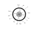
なお、前述したように、図1は、実施の形態1のガス遮断器100と本実施の形態2のガス遮断器101との断面図を兼ねる。図12は、図1に示す一点鎖線C2に示す位置における軸線Aに平行な方向から見たガス遮断器101の断面図である。
さらに、図中の図1~図11と同一記号および同一符号は、実施の形態1と同様あるいは同等品であるので、詳細な説明は省略する。
また、ガス遮断器101の電流遮断動作は、ガス遮断器100と同様であるので、詳細な説明は省略する。
なお、前述したように、図1は、実施の形態1のガス遮断器100と本実施の形態2のガス遮断器101との断面図を兼ねる。図12は、図1に示す一点鎖線C2に示す位置における軸線Aに平行な方向から見たガス遮断器101の断面図である。
さらに、図中の図1~図11と同一記号および同一符号は、実施の形態1と同様あるいは同等品であるので、詳細な説明は省略する。
また、ガス遮断器101の電流遮断動作は、ガス遮断器100と同様であるので、詳細な説明は省略する。
図12を参照して、4個の噴出口7v1~7v4は、軸線Aの側方から開口される。また、噴出口7v1の開口方向v1は、軸線Aと同一平面内に配置されない。すなわち、噴出口7v1の開口方向v1と軸線Aとは、ねじれの位置に配置される。同様に、噴出口7v2の開口方向v2と軸線Aとは、ねじれの位置に配置され、噴出口7v3の開口方向v3と軸線Aとは、ねじれの位置に配置され、噴出口7v4の開口方向v4と軸線Aとは、ねじれの位置に配置される。言い換えると、噴出口7v1の開口方向v1、噴出口7v2の開口方向v2、噴出口7v3の開口方向v3および噴出口7v4の開口方向v4を、固定電極1の軸線Aを法線とする平面に投影すると、開口方向v1~v4は、固定電極1の軸線Aとずれた位置に配置される。
このような配置により、アーク放電Eが軸線Aを通過せずアーク放電Eが軸線A以外の場所を通過した場合でも、ガス流Stuを、アーク放電Eに効率的に吹き付けることにより、アーク放電Eを消弧することができる。
このような配置により、アーク放電Eが軸線Aを通過せずアーク放電Eが軸線A以外の場所を通過した場合でも、ガス流Stuを、アーク放電Eに効率的に吹き付けることにより、アーク放電Eを消弧することができる。
すなわち、本実施の形態2は、実施の形態1と同様に、電流値の大きさに拘わらず高い電流遮断性能を備える。よって、対応電流値範囲の広いガス遮断器101を提供することができる。
実施の形態3.
図13は、この発明の実施の形態3に係るガス遮断器102の断面図である。本実施の形態では、第2の熱パッファ室Tp2をさらに設けた点が実施の形態1と相違する。なお、図中の図1~図12と同一記号および同一符号は、実施の形態1と同様あるいは同等品であるので、詳細な説明は省略する。
図13は、この発明の実施の形態3に係るガス遮断器102の断面図である。本実施の形態では、第2の熱パッファ室Tp2をさらに設けた点が実施の形態1と相違する。なお、図中の図1~図12と同一記号および同一符号は、実施の形態1と同様あるいは同等品であるので、詳細な説明は省略する。
可動側筐体3の内壁面には、可動側筐体3の内部空間を機械パッファ室Mpと第2の熱パッファ室Tp2とに区画する隔壁12が形成されている。隔壁12と可動側筐体3とピストン4と可動電極2とで囲まれた空間は、機械パッファ室Mpである。隔壁12と可動側筐体3と可動電極2とで囲まれた空間は、第2の熱パッファ室Tp2である。機械パッファ室Mpと第1の熱パッファ室Tpと第2の熱パッファ室Tp2とは、軸線Aの方向に直列に配置されている。機械パッファ室Mpは、軸線Aの方向において、第2の熱パッファ室Tp2を挟んで第1の熱パッファ室Tpと反対側に配置されている。つまり、第2の熱パッファ室Tp2は、軸線Aの方向において、機械パッファ室Mpと第1の熱パッファ室Tpとの間に配置されている。隔壁12は、中心に貫通孔が形成された円板状の部分である。隔壁12の貫通孔には、可動電極2が通されている。隔壁12の貫通孔の径は、可動電極2の外径よりも大きい。そのため、隔壁12と可動電極2との間には、隙間が形成される。この隙間、すなわち隔壁12の貫通孔のうち可動電極2が通る部分以外の部分は、機械パッファ室Mpと第2の熱パッファ室Tp2とを連通する第1の吸出口Mnuとなる。第1の吸出口Mnuは、絶縁性ガスの流路となる。絶縁性ガスは、第2の熱パッファ室Tp2内から第1の吸出口Mnuを通って、機械パッファ室Mp内に流入する。また、絶縁性ガスは、機械パッファ室Mp内から第1の吸出口Mnuを通って、第2の熱パッファ室Tp2内に流出する。可動電極2の外周面には、環状の逆止弁13が配置されている。言い換えると、逆止弁13の中心に形成された貫通孔には、可動電極2が通されている。逆止弁13は、第2の熱パッファ室Tp2内に配置されている。逆止弁13は、軸線Aの方向において、可動体部21と相対的に移動可能である。逆止弁13は、第1の吸出口Mnuを閉塞および第1の吸出口Mnuを開放する。以下、逆止弁13が第1の吸出口Mnuを閉塞している状態を「第1の吸出口Mnuの閉塞状態」と称し、逆止弁13が第1の吸出口Mnuを開放している状態を「第1の吸出口Mnuの開放状態」と称する。
可動側筐体3のうち第2の熱パッファ室Tp2を挟んで隔壁12と反対側には、第2の吸出口Mnvが形成されている。第2の吸出口Mnvは、絶縁性ガスの流路となる。絶縁性ガスは、第2の吸出口Mnvを通って、第2の熱パッファ室Tp2内に流入する。また、絶縁性ガスは、第2の吸出口Mnvを通って、第2の熱パッファ室Tp2内から流出する。第2の吸出口Mnvは、本実施の形態では可動側筐体3の内壁面に接触するノズル7の一部と可動電極2との間に形成されているが、可動側筐体3の内壁面と可動電極2との間に形成されてもよい。なお、第1の熱パッファ室Tpは、機械パッファ室Mpからアーク放電Eに向かう絶縁性ガスの流路とは異なる箇所に配置される。
次に、大電流遮断時におけるガス遮断器102の動作について説明する。大電流遮断時には、発生するアーク放電Eの熱エネルギーが高いため、第2の熱パッファ室Tp2における絶縁性ガスの圧力が十分に高まる。その結果、大電流遮断時には、第2の熱パッファ室Tp2内における絶縁ガスの圧力が、機械パッファ室Mp内における絶縁ガスの圧力よりも高い。そのため、逆止弁13は、機械パッファ室Mpに向けて移動する。逆止弁13は、隔壁12のうち第2の熱パッファ室Tp2に臨む面と接触して第1の吸出口Mnuを閉塞する。具体的な図示は省略するが、第1の吸出口Mnuの閉塞状態において、図5に示す時刻T1を経過して時刻T2までの間に、絶縁性ガスは、アーク放電Eの周囲から第2の吸出口Mnvを通って、第2の熱パッファ室Tp2内に流入するとともに、アーク放電Eの周囲から吸入口7nを通って、第1の熱パッファ室Tp内に流入する。そのため、第2の熱パッファ室Tp2内と第1の熱パッファ室Tp内とにおける絶縁性ガスの圧力が上昇する。第1の吸出口Mnuの閉塞状態において、図5に示す時刻T2を経過して時刻T3までの間に、絶縁性ガスは、第2の熱パッファ室Tp2内から第2の吸出口Mnvを通って、アーク放電Eに向かって吹き付けられるとともに、第1の熱パッファ室Tp内から噴出口7uを通って、アーク放電Eに向かって吹き付けられる。絶縁ガスがアーク放電Eに向かって吹き付けられることによって、アーク放電Eが消弧される。
次に、小電流遮断時におけるガス遮断器102の動作について説明する。小電流遮断時には、発生するアーク放電Eの熱エネルギーが低いため、第2の熱パッファ室Tp2における絶縁性ガスの圧力が十分に高くならない。その結果、小電流遮断時には、機械パッファ室Mp内における絶縁ガスの圧力が、第2の熱パッファ室Tp2内における絶縁ガスの圧力よりも高い。そのため、逆止弁13は、機械パッファ室Mpから離れる方向に移動する。逆止弁13は、隔壁12から離れて第1の吸出口Mnuを開放する。具体的な図示は省略するが、第1の吸出口Mnuの開放状態において、図5に示す時刻T1を経過して時刻T2までの間に、絶縁性ガスは、アーク放電Eの周囲から第2の吸出口Mnvを通って、第2の熱パッファ室Tp2内に流入するとともに、アーク放電Eの周囲から吸入口7nを通って、第1の熱パッファ室Tp内に流入する。そのため、第2の熱パッファ室Tp2内と第1の熱パッファ室Tp内とにおける絶縁性ガスの圧力が上昇する。また、第1の吸出口Mnuの開放状態において、図5に示す時刻T1を経過して時刻T2までの間に、機械パッファ室Mp内の絶縁ガスは、第1の吸出口Mnuを通って、第2の熱パッファ室Tp2内に流入する。第1の吸出口Mnuの開放状態において、図5に示す時刻T2を経過して時刻T3までの間に、絶縁性ガスは、機械パッファ室Mp内から第1の吸出口Mnuを通って第2の熱パッファ室Tp2内に流入した後、第2の吸出口Mnvを経てアーク放電Eに向かって吹き付けられる。つまり、第2の熱パッファ室Tp2は、機械パッファ室Mpからアーク放電Eに向かう絶縁性ガスの流路になる。また、第1の吸出口Mnuの開放状態において、図5に示す時刻T2を経過して時刻T3までの間に、絶縁ガスは、第1の熱パッファ室Tp内から噴出口7uを通って、アーク放電Eに向かって吹き付けられる。絶縁ガスがアーク放電Eに向かって吹き付けられることによって、アーク放電Eが消弧される。
ここで、熱パッファ室の容積は、ガス遮断器102に求められる大電流遮断性能に基づき決定される。本実施の形態では、第1の熱パッファ室Tpおよび第2の熱パッファ室Tp2の2つの熱パッファ室が設けられることにより、ガス遮断器102に求められる大電流遮断性能を実現する上で必要な熱パッファ室の容積を、第1の熱パッファ室Tpと第2の熱パッファ室Tp2とに分けられる。つまり、第1の熱パッファ室Tpの容積分だけ第2の熱パッファ室Tp2の容積を小さくできる。そのため、機械パッファ室Mpからアーク放電Eに向かう絶縁性ガスの流路のみに熱パッファ室が設けられる場合に比べて、ガス遮断器102を小型化できる。一方、ガス遮断器102の小電流遮断性能は、機械パッファ室Mpと第2の熱パッファ室Tp2とにおける絶縁性ガスの圧縮率で決まる。詳しくは、機械パッファ室Mpと第2の熱パッファ室Tp2とにおける絶縁性ガスの圧縮率が高いほど、ガス遮断器102の小電流遮断性能が向上する。第2の熱パッファ室Tp2が、機械パッファ室Mpからアーク放電Eに向かう絶縁性ガスの流路になる構造においては、第2の熱パッファ室Tp2の容積が大きいほど、機械パッファ室Mpと第2の熱パッファ室Tp2とにおける絶縁性ガスの圧縮率が低くなる。その結果、小電流遮断時に機械パッファ室Mpにおける絶縁性ガスの圧力の上昇が阻害される。この点、本実施の形態では、第1の熱パッファ室Tpの容積分だけ第2の熱パッファ室Tp2の容積を小さくできるため、機械パッファ室Mpからアーク放電Eに向かう絶縁性ガスの流路のみに熱パッファ室が設けられる場合に比べて、第2の熱パッファ室Tp2における絶縁性ガスの圧縮率が高い。よって、ガス遮断器102の小電流遮断性能を向上させることができる。
なお、実施の形態1~3では、ノズル7をアブレーション性材料で形成しても良い。この場合、ガス流Stnが吸入口7nから第1の熱パッファ室Tpの内部に流入したときに、ガス流Stnの熱によりアブレーション性材料が蒸発する。それにより、第1の熱パッファ室Tpの内部の圧力が上昇し、噴出口7uから噴出されるガス流Stuの圧力は上昇する。
すなわち、アーク放電Eにより高圧なガス流Stuを吹き付け、効率的にアーク放電Eを消弧することができる。
すなわち、アーク放電Eにより高圧なガス流Stuを吹き付け、効率的にアーク放電Eを消弧することができる。
さらに、第1の熱パッファ室Tpを、アブレーション性材料で形成しても良く、さらに、第1の熱パッファ室Tpの内部に、アブレーション性材料を配置しても良い。このような場合でも第1の熱パッファ室Tpの内部の圧力が上昇し、噴出口7uから噴出されるガス流Stuの圧力は上昇する効果を得る。
なお、アブレーション性材料には、ポリテトラフルオロエチレン(PTFE)やパーフルオロアルキルビニルエーテル共重合体(PFA)が挙げられる。
さらに、アブレーション性材料には、パーフルオロエーテル系重合体、フッ素エラストマー、及び4-ビニルオキシ-1-ブテン(BVE)環化重合体からなる群より選ばれた少なくとも1種の化合物を用いることができる。
なお、アブレーション性材料には、ポリテトラフルオロエチレン(PTFE)やパーフルオロアルキルビニルエーテル共重合体(PFA)が挙げられる。
さらに、アブレーション性材料には、パーフルオロエーテル系重合体、フッ素エラストマー、及び4-ビニルオキシ-1-ブテン(BVE)環化重合体からなる群より選ばれた少なくとも1種の化合物を用いることができる。
また、実施の形態1~3では、ノズル7は4個の吸入口7nと4個の噴出口7uとを有することを説明したが、この発明は、吸入口7nおよび噴出口7uの数を限定するものではなく、吸入口7nおよび噴出口7uの数は、ガス遮断器100~102を設計する上で適宜決められるものである。
なお、実施の形態1では、各々の噴出口7uの開口方向と軸線Aとを含む平面内で交差するように配置されること、実施の形態2では、各々の噴出口7vの開口方向と軸線Aとはねじれの位置に配置されることを説明したが、本発明は、噴出口(7u、7v)の開口方向に限定されるものではない。
さらに、この発明は、その発明の範囲内において、各実施の形態を自由に組み合わせることが可能であるし、各実施の形態を適宜変更、省略することが可能である。
例えば、ノズル7に、軸線Aの側方から軸線Aに向かって開口する噴出口7uと、ねじれの位置に開口する噴出口7vとの両方を配置しても良い。
例えば、ノズル7に、軸線Aの側方から軸線Aに向かって開口する噴出口7uと、ねじれの位置に開口する噴出口7vとの両方を配置しても良い。
1 固定電極、2 可動電極、3 可動側筐体、4 ピストン、7 ノズル、7n 吸入口、7u,7v,7v1~7v4 噴出口、8 シリンダー部、12 隔壁、13 逆止弁、100,101,102 ガス遮断器、A 軸線、Mnu 第1の吸出口、Mnv 第2の吸出口、Mp 機械パッファ室、Tp 第1の熱パッファ室、Tp2 第2の熱パッファ室。
Claims (11)
- 絶縁性ガスが充填されるタンク内に、
導電性の固定電極と、
前記固定電極の軸線上を可動し前記固定電極と接離可能な可動電極と、
前記可動電極と連動し前記軸線を包囲する第1の可動側筐体と、
前記第1の可動側筐体とで機械パッファ室を形成するピストンと、
前記可動電極と連動し前記軸線の方向に前記第1の可動側筐体と直列に位置する第2の可動側筐体と、
前記第2の可動側筐体とで第1の熱パッファ室を形成するノズルとを備え、
前記第1の可動側筐体には、前記絶縁性ガスを前記機械パッファ室内に吸入し、かつ、前記絶縁性ガスを前記機械パッファ室内から噴出するための第1の吸出口が形成され、
前記ノズルには、前記絶縁性ガスを前記第1の熱パッファ室内に吸入するための吸入口と、前記第1の熱パッファ室内から前記固定電極と前記可動電極との間に向けて前記絶縁性ガスを噴出するための噴出口とが形成されることを特徴とするガス遮断器。 - 前記第1の可動側筐体の内壁面には、前記第1の可動側筐体の内部空間を前記機械パッファ室と第2の熱パッファ室とに区画する隔壁が形成され、
前記隔壁には、前記機械パッファ室と前記第2の熱パッファ室とを連通する前記第1の吸出口が形成され、
前記機械パッファ室は、前記軸線の方向において、前記第2の熱パッファ室を挟んで前記第1の熱パッファ室と反対側に配置され、
前記第1の可動側筐体のうち前記第2の熱パッファ室を挟んで前記隔壁と反対側には、前記絶縁性ガスを前記第2の熱パッファ室内に吸入し、かつ、前記第2の熱パッファ室内から前記固定電極と前記可動電極との間に向けて前記絶縁性ガスを噴出するための第2の吸出口が形成されていることを特徴とする請求項1に記載のガス遮断器。 - 前記軸線の側方から断面視するとき、前記機械パッファ室と前記第1の熱パッファ室とは、前記軸線の方向に直列に配置されることを特徴とする請求項1または2に記載のガス遮断器。
- 前記第1の吸出口と前記吸入口とは、対向して配置されることを特徴とする請求項1に記載のガス遮断器。
- 前記可動電極と前記固定電極とが接続した状態から前記可動電極が可動する過程において、前記固定電極の先端が前記噴出口の開口位置を通過することを特徴とする請求項1から4のいずれか1項に記載のガス遮断器。
- 前記噴出口は、前記軸線の側方から開口し、前記開口の方向と前記軸線とを含む平面で交差することを特徴とする請求項1から5のいずれか1項に記載のガス遮断器。
- 前記噴出口は、前記軸線の側方から開口し、前記開口の方向と前記軸線とはねじれの位置にあることを特徴とする請求項1から5のいずれか1項に記載のガス遮断器。
- 前記第1の熱パッファ室は、アブレーション性材料で形成されることを特徴とする請求項1から7のいずれか1項に記載のガス遮断器。
- 前記第1の熱パッファ室の内部に、アブレーション性材料を配置することを特徴とする請求項1から7のいずれか1項に記載のガス遮断器。
- 前記アブレーション性材料は、ポリテトラフルオロエチレンあるいはパーフルオロアルキルビニルエーテル共重合体であることを特徴とする請求項8または9に記載のガス遮断器。
- 前記アブレーション性材料は、パーフルオロエーテル系重合体、フッ素エラストマー、及び4-ビニルオキシ-1-ブテン環化重合体からなる群より選ばれた少なくとも1種の化合物であることを特徴とする請求項8または9に記載のガス遮断器。
Priority Applications (2)
| Application Number | Priority Date | Filing Date | Title |
|---|---|---|---|
| JP2020552997A JP6961105B2 (ja) | 2018-10-24 | 2019-09-24 | ガス遮断器 |
| EP19877047.1A EP3872829B1 (en) | 2018-10-24 | 2019-09-24 | Gas circuit breaker |
Applications Claiming Priority (2)
| Application Number | Priority Date | Filing Date | Title |
|---|---|---|---|
| JP2018-200097 | 2018-10-24 | ||
| JP2018200097 | 2018-10-24 |
Publications (1)
| Publication Number | Publication Date |
|---|---|
| WO2020084984A1 true WO2020084984A1 (ja) | 2020-04-30 |
Family
ID=70330985
Family Applications (1)
| Application Number | Title | Priority Date | Filing Date |
|---|---|---|---|
| PCT/JP2019/037360 Ceased WO2020084984A1 (ja) | 2018-10-24 | 2019-09-24 | ガス遮断器 |
Country Status (3)
| Country | Link |
|---|---|
| EP (1) | EP3872829B1 (ja) |
| JP (1) | JP6961105B2 (ja) |
| WO (1) | WO2020084984A1 (ja) |
Cited By (1)
| Publication number | Priority date | Publication date | Assignee | Title |
|---|---|---|---|---|
| JP2024124633A (ja) * | 2023-03-03 | 2024-09-13 | 株式会社東芝 | ガス遮断器 |
Citations (5)
| Publication number | Priority date | Publication date | Assignee | Title |
|---|---|---|---|---|
| JPS61118919A (ja) * | 1984-11-14 | 1986-06-06 | 株式会社東芝 | ガス絶縁遮断器 |
| JPH04284319A (ja) * | 1991-03-13 | 1992-10-08 | Hitachi Ltd | ガス遮断器 |
| JPH04286821A (ja) * | 1991-03-18 | 1992-10-12 | Fuji Electric Co Ltd | パッファ形ガス遮断器 |
| JP2003297200A (ja) | 2002-04-01 | 2003-10-17 | Toshiba Corp | ガス遮断器 |
| JP2012054097A (ja) * | 2010-09-01 | 2012-03-15 | Mitsubishi Electric Corp | ガス遮断器 |
Family Cites Families (4)
| Publication number | Priority date | Publication date | Assignee | Title |
|---|---|---|---|---|
| US3946180A (en) * | 1974-04-22 | 1976-03-23 | I-T-E Imperial Corporation | Downstream injection nozzle for puffer circuit interrupter |
| DE2710868A1 (de) * | 1977-03-12 | 1978-09-14 | Licentia Gmbh | Autopneumatischer leistungsschalter mit isolierstoffduese |
| JPS5916234A (ja) * | 1982-07-19 | 1984-01-27 | 株式会社富士電機総合研究所 | ガスしや断器のしや断室 |
| US9147543B2 (en) * | 2010-12-07 | 2015-09-29 | Mitsubishi Electric Corporation | Gas circuit breaker |
-
2019
- 2019-09-24 JP JP2020552997A patent/JP6961105B2/ja active Active
- 2019-09-24 WO PCT/JP2019/037360 patent/WO2020084984A1/ja not_active Ceased
- 2019-09-24 EP EP19877047.1A patent/EP3872829B1/en active Active
Patent Citations (5)
| Publication number | Priority date | Publication date | Assignee | Title |
|---|---|---|---|---|
| JPS61118919A (ja) * | 1984-11-14 | 1986-06-06 | 株式会社東芝 | ガス絶縁遮断器 |
| JPH04284319A (ja) * | 1991-03-13 | 1992-10-08 | Hitachi Ltd | ガス遮断器 |
| JPH04286821A (ja) * | 1991-03-18 | 1992-10-12 | Fuji Electric Co Ltd | パッファ形ガス遮断器 |
| JP2003297200A (ja) | 2002-04-01 | 2003-10-17 | Toshiba Corp | ガス遮断器 |
| JP2012054097A (ja) * | 2010-09-01 | 2012-03-15 | Mitsubishi Electric Corp | ガス遮断器 |
Non-Patent Citations (1)
| Title |
|---|
| See also references of EP3872829A4 |
Cited By (1)
| Publication number | Priority date | Publication date | Assignee | Title |
|---|---|---|---|---|
| JP2024124633A (ja) * | 2023-03-03 | 2024-09-13 | 株式会社東芝 | ガス遮断器 |
Also Published As
| Publication number | Publication date |
|---|---|
| EP3872829A1 (en) | 2021-09-01 |
| JPWO2020084984A1 (ja) | 2021-04-30 |
| EP3872829B1 (en) | 2024-07-10 |
| JP6961105B2 (ja) | 2021-11-05 |
| EP3872829A4 (en) | 2021-12-22 |
Similar Documents
| Publication | Publication Date | Title |
|---|---|---|
| JP5516568B2 (ja) | パッファ形ガス遮断器 | |
| US10964498B2 (en) | Gas-insulated low- or medium-voltage load break switch | |
| JP2008210710A (ja) | 電力用ガス遮断器 | |
| JP2018160436A (ja) | ガス遮断器 | |
| WO2013175565A1 (ja) | ガス遮断器 | |
| JP6961105B2 (ja) | ガス遮断器 | |
| WO2018066119A1 (ja) | ガス遮断器 | |
| WO2018225255A1 (ja) | ガス遮断器 | |
| JP2019091590A (ja) | ガス遮断器 | |
| WO2019150550A1 (ja) | ガス遮断器 | |
| WO2019073660A1 (ja) | ガス遮断器 | |
| JP6915077B2 (ja) | ガス遮断器 | |
| JP2024124633A (ja) | ガス遮断器 | |
| JP7155283B2 (ja) | ガス遮断器 | |
| JP7612893B2 (ja) | ガス遮断器 | |
| JPH10269912A (ja) | ガス遮断器 | |
| JP2015162330A (ja) | ガス遮断器 | |
| CN111433878B (zh) | 气体断路器 | |
| JP2016143499A (ja) | ガス遮断器 | |
| JP2015023006A (ja) | ガス遮断器 | |
| JP2007179830A (ja) | ガス遮断器 | |
| JP2016062650A (ja) | ガス遮断器 | |
| WO2019092862A1 (ja) | ガス遮断器 | |
| WO2020003854A1 (ja) | ガス遮断器 | |
| JP2020091939A (ja) | ガス遮断器 |
Legal Events
| Date | Code | Title | Description |
|---|---|---|---|
| 121 | Ep: the epo has been informed by wipo that ep was designated in this application |
Ref document number: 19877047 Country of ref document: EP Kind code of ref document: A1 |
|
| ENP | Entry into the national phase |
Ref document number: 2020552997 Country of ref document: JP Kind code of ref document: A |
|
| NENP | Non-entry into the national phase |
Ref country code: DE |
|
| ENP | Entry into the national phase |
Ref document number: 2019877047 Country of ref document: EP Effective date: 20210525 |