WO2020085043A1 - 扉開閉装置及びヒンジ - Google Patents
扉開閉装置及びヒンジ Download PDFInfo
- Publication number
- WO2020085043A1 WO2020085043A1 PCT/JP2019/039266 JP2019039266W WO2020085043A1 WO 2020085043 A1 WO2020085043 A1 WO 2020085043A1 JP 2019039266 W JP2019039266 W JP 2019039266W WO 2020085043 A1 WO2020085043 A1 WO 2020085043A1
- Authority
- WO
- WIPO (PCT)
- Prior art keywords
- door
- link
- main arm
- side member
- main
- Prior art date
- Legal status (The legal status is an assumption and is not a legal conclusion. Google has not performed a legal analysis and makes no representation as to the accuracy of the status listed.)
- Ceased
Links
Images



Classifications
-
- E—FIXED CONSTRUCTIONS
- E05—LOCKS; KEYS; WINDOW OR DOOR FITTINGS; SAFES
- E05D—HINGES OR SUSPENSION DEVICES FOR DOORS, WINDOWS OR WINGS
- E05D15/00—Suspension arrangements for wings
- E05D15/28—Suspension arrangements for wings supported on arms movable in horizontal plane
- E05D15/32—Suspension arrangements for wings supported on arms movable in horizontal plane with two pairs of pivoted arms
- E05D15/34—Suspension arrangements for wings supported on arms movable in horizontal plane with two pairs of pivoted arms with wings opening parallel to themselves
-
- E—FIXED CONSTRUCTIONS
- E05—LOCKS; KEYS; WINDOW OR DOOR FITTINGS; SAFES
- E05D—HINGES OR SUSPENSION DEVICES FOR DOORS, WINDOWS OR WINGS
- E05D3/00—Hinges with pins
- E05D3/06—Hinges with pins with two or more pins
-
- E—FIXED CONSTRUCTIONS
- E06—DOORS, WINDOWS, SHUTTERS, OR ROLLER BLINDS IN GENERAL; LADDERS
- E06B—FIXED OR MOVABLE CLOSURES FOR OPENINGS IN BUILDINGS, VEHICLES, FENCES OR LIKE ENCLOSURES IN GENERAL, e.g. DOORS, WINDOWS, BLINDS, GATES
- E06B7/00—Special arrangements or measures in connection with doors or windows
- E06B7/28—Other arrangements on doors or windows, e.g. door-plates, windows adapted to carry plants, hooks for window cleaners
- E06B7/36—Finger guards or other measures preventing harmful access between the door and the door frame
-
- E—FIXED CONSTRUCTIONS
- E06—DOORS, WINDOWS, SHUTTERS, OR ROLLER BLINDS IN GENERAL; LADDERS
- E06B—FIXED OR MOVABLE CLOSURES FOR OPENINGS IN BUILDINGS, VEHICLES, FENCES OR LIKE ENCLOSURES IN GENERAL, e.g. DOORS, WINDOWS, BLINDS, GATES
- E06B7/00—Special arrangements or measures in connection with doors or windows
- E06B7/28—Other arrangements on doors or windows, e.g. door-plates, windows adapted to carry plants, hooks for window cleaners
- E06B7/36—Finger guards or other measures preventing harmful access between the door and the door frame
- E06B7/367—Finger guards or other measures preventing harmful access between the door and the door frame by covering the gap between the door and the door frame at the hinge side
-
- E—FIXED CONSTRUCTIONS
- E05—LOCKS; KEYS; WINDOW OR DOOR FITTINGS; SAFES
- E05D—HINGES OR SUSPENSION DEVICES FOR DOORS, WINDOWS OR WINGS
- E05D11/00—Additional features or accessories of hinges
- E05D11/10—Devices for preventing movement between relatively-movable hinge parts
- E05D11/1007—Devices for preventing movement between relatively-movable hinge parts with positive locking
-
- E—FIXED CONSTRUCTIONS
- E05—LOCKS; KEYS; WINDOW OR DOOR FITTINGS; SAFES
- E05D—HINGES OR SUSPENSION DEVICES FOR DOORS, WINDOWS OR WINGS
- E05D3/00—Hinges with pins
- E05D3/06—Hinges with pins with two or more pins
- E05D3/14—Hinges with pins with two or more pins with four parallel pins and two arms
-
- E—FIXED CONSTRUCTIONS
- E05—LOCKS; KEYS; WINDOW OR DOOR FITTINGS; SAFES
- E05Y—INDEXING SCHEME ASSOCIATED WITH SUBCLASSES E05D AND E05F, RELATING TO CONSTRUCTION ELEMENTS, ELECTRIC CONTROL, POWER SUPPLY, POWER SIGNAL OR TRANSMISSION, USER INTERFACES, MOUNTING OR COUPLING, DETAILS, ACCESSORIES, AUXILIARY OPERATIONS NOT OTHERWISE PROVIDED FOR, APPLICATION THEREOF
- E05Y2201/00—Constructional elements; Accessories therefor
- E05Y2201/60—Suspension or transmission members; Accessories therefor
- E05Y2201/622—Suspension or transmission members elements
- E05Y2201/624—Arms
-
- E—FIXED CONSTRUCTIONS
- E05—LOCKS; KEYS; WINDOW OR DOOR FITTINGS; SAFES
- E05Y—INDEXING SCHEME ASSOCIATED WITH SUBCLASSES E05D AND E05F, RELATING TO CONSTRUCTION ELEMENTS, ELECTRIC CONTROL, POWER SUPPLY, POWER SIGNAL OR TRANSMISSION, USER INTERFACES, MOUNTING OR COUPLING, DETAILS, ACCESSORIES, AUXILIARY OPERATIONS NOT OTHERWISE PROVIDED FOR, APPLICATION THEREOF
- E05Y2800/00—Details, accessories and auxiliary operations not otherwise provided for
- E05Y2800/10—Additional functions
- E05Y2800/13—Sequential actions
-
- E—FIXED CONSTRUCTIONS
- E05—LOCKS; KEYS; WINDOW OR DOOR FITTINGS; SAFES
- E05Y—INDEXING SCHEME ASSOCIATED WITH SUBCLASSES E05D AND E05F, RELATING TO CONSTRUCTION ELEMENTS, ELECTRIC CONTROL, POWER SUPPLY, POWER SIGNAL OR TRANSMISSION, USER INTERFACES, MOUNTING OR COUPLING, DETAILS, ACCESSORIES, AUXILIARY OPERATIONS NOT OTHERWISE PROVIDED FOR, APPLICATION THEREOF
- E05Y2900/00—Application of doors, windows, wings or fittings thereof
- E05Y2900/20—Application of doors, windows, wings or fittings thereof for furniture, e.g. cabinets
Definitions
- the present invention relates to a door opening / closing device and a hinge for moving a door in parallel between a closed position and an open position.
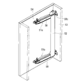
- the applicant has proposed the door opening / closing device shown in FIG. 11 as this kind of door opening / closing device (see Patent Document 1).
- the door opening / closing device includes a pair of hinges 51a and 51b and a connecting bar 52 connected to the pair of hinges 51a and 51b.
- each of the hinges 51a and 51b includes a main body side member 55 attached to the inner surface of the main body 53, a door side member 56 attached to the back surface of the door 54, a main body side member 55 and a door side member 56.
- a main arm 58 that is rotatably connected, a first link 57 that is rotatably connected to the main body side member 55 and the door side member 56, and a first link rotatably connected to the main body side member 55 and the door side member 56. 2 links 59, and.
- the three first axes 58a, 57a, 59a which are the rotation centers of the main arm 58, the first link 57, and the second link 59 with respect to the main body side member 55, are arranged at the vertices of a triangle when viewed in the axial direction.
- the three second shafts 58b, 57b, 59b which are the rotation centers of the main arm 58, the first link 57, and the second link 59 with respect to the door-side member 56, are arranged at the vertices of a triangle when viewed in the axial direction.
- the main body side member 55, the door side member 56, the main arm 58, and the first link 57 constitute a mechanical parallel link mechanism (also called a parallel crank mechanism). Therefore, the door 54 moves in parallel between the closed position and the open position. However, if only the main body side member 55, the door side member 56, the main arm 58, and the first link 57 are used, a thought may occur when the door 54 is opened and closed, and the mechanism becomes unstable. Therefore, the second link 59 is added to prevent the mechanism from becoming unstable.
- the main arm 58 has a bent portion 58c. This is for preventing the main arm 58 from interfering with the main body 53 or an adjacent door (not shown) at the open position of the door 54.
- a connecting bar 52 is connected to the main arms 58 of the pair of hinges 51a and 51b. This is because even if the door 54 is heavy, the pair of hinges 51a and 51b are interlocked to stably open and close the door 54.
- the connecting bar 52 is attached to the main body 53 side of the main arm 58 and near the bent portion 58c of the main arm 58. Since the connecting bar 52 passes from the top to the bottom of the main body 53, the connecting bar 52 interferes with the storage, and there is a problem that the storage space of the main body 53 becomes narrow.
- the present invention has been made in view of the above problems, and an object of the present invention is to provide a door opening / closing device that can widen the storage space of the main body.
- one aspect of the present invention includes at least two hinges and a connecting bar connected to the at least two hinges, and each hinge is a main body side member attached to an inner surface of a main body.
- a door side member attached to the back surface of the door, a main arm rotatably connected to the main body side member and the door side member, and a main arm rotatably connected to the main body side member and the door side member.
- 1 link, and a second link rotatably connected to the main body side member and the door side member, of the rotation of the main arm, the first link and the second link with respect to the main body side member.
- the three first axes that are the centers are arranged at the vertices of a triangle in the axial direction
- the three second axes that are the centers of rotation of the main arm, the first link, and the second link with respect to the door-side member are The axial view
- the main arm has a bent portion, and the door is translated in parallel between a closed position and an open position, the connecting bar is on the door side of the main arm.
- the center of the connecting bar in the width direction is defined by the first axis of the main arm and the second axis of the main arm.
- the door opening / closing device is arranged closer to the second shaft than the center of the door.
- Another aspect of the present invention is a main body side member attached to an inner surface of a main body, a door side member attached to a back surface of a door, a main arm rotatably connected to the main body side member and the door side member, A first link rotatably connected to the main body side member and the door side member; and a second link rotatably connected to the main body side member and the door side member, the main body side member With respect to the main arm, the first links and the three first axes that are the centers of rotation of the second links are arranged at the vertices of a triangle in the axial direction, and the main arm with respect to the door side member, the first link And three second axes that are the centers of rotation of the second links are arranged at the apexes of a triangle in the axial direction, the main arm has a bent portion, and the door is between the closed position and the open position.
- a center is a hinge arranged closer to the second shaft than a center between the first shaft of the main arm and the second shaft of the main arm.
- the connecting bar can be brought close to the back surface of the door in the closed position. Therefore, the storage space of the main body can be widened.
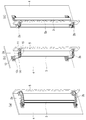
- FIG. 1 is a front perspective view of a cabinet using a door opening / closing device according to an embodiment of the present invention
- FIG. 1A is a door closed position
- FIG. 1B is an intermediate position of the door
- FIG. 2 (a) shows the door closed position
- FIG. 2 (b) shows the door intermediate position
- FIG. 2 (c) shows the door open position
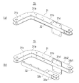
- FIG.3 (a) shows the perspective view of the hinge seen from the main body side
- FIG.3 (b) shows the perspective view of the hinge seen from the door side
- FIG.3 (a) shows the perspective view of the hinge seen from the main body side
- FIG.3 (b) shows the perspective view of the hinge seen from the door side
- FIG.3 (a) shows the perspective view of the hinge seen from the main body side
- FIG.3 (b) shows the perspective view of the hinge seen from the door side
- FIG.3 (a) shows the perspective view of the hinge seen from the main body side
- FIG. 5 is a perspective view of the main arm of the present embodiment (FIG. 5A shows a state in which the assist arm is incorporated in the arm body, and FIG. 5B shows a state in which the assist arm is removed from the arm body).
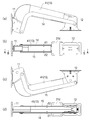
- FIG. 6 (a) is a plan view
- FIG. 6 (b) is a right side view
- FIG. 6 (c) is a bottom view
- FIG. 6 (d) is a left side view.
- FIG. 7 (a) is an AA sectional view of FIG. 6 (b)
- FIG. 7 (b) is a BB sectional view of FIG. 6 (b). ).
- FIG. 7 (a) is an AA sectional view of FIG. 6 (b)
- FIG. 7 (b) is a BB sectional view of FIG. 6 (b).
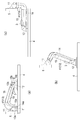
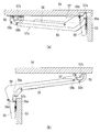
- FIG. 8 is a plan view of the door opening / closing device of the present embodiment (FIG. 8A shows a door closed position, FIG. 8B shows an intermediate position of the door, and FIG. 8C shows an open position of the door). It is a top view of the door opening and closing device of this embodiment. It is a rear side perspective view of the cabinet which attached the shelf. It is a perspective view of the conventional door opening and closing device.
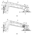
- FIG. 12 is a plan view of a hinge of a conventional door opening / closing device (FIG. 12 (a) shows a door closed position, and FIG. 12 (b) shows a door open position).
- the door opening / closing device of the embodiment of the present invention will be described in detail below with reference to the accompanying drawings.
- the door opening / closing device of the present invention can be embodied in various forms, and is not limited to the embodiments described in the present specification. This embodiment is provided with the intention of making it possible for those skilled in the art to fully understand the scope of the invention by sufficiently disclosing the specification.
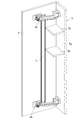
- FIG. 1 is a front perspective view of a cabinet using a door opening / closing device 1 according to an embodiment of the present invention (the door 4 is indicated by a chain double-dashed line), and FIG. 2 is a rear perspective view of the cabinet (of the main body 5). A part is shown by a broken line).
- the configuration of the door opening / closing device 1 will be described using the direction when the door 4 is viewed from the front, that is, the front-back, up-down, left-right directions shown in the drawing.
- the arrangement of the door opening / closing device 1 is not limited to this.
- FIG. 1A shows the closed position of the door 4
- FIG. 1B shows the intermediate position of the door 4
- FIG. 1C shows the opened position of the door 4.
- Reference numeral 2a is an upper hinge
- 2b is a lower hinge
- 3 is a connecting bar that connects the hinges 2a and 2b.
- the door opening / closing device 1 includes a pair of hinges 2a and 2b and a connecting bar 3 connected to the pair of hinges 2a and 2b.
- the hinge 2 a is a main body side member 11 attached to the inner surface of the side plate 5 a of the main body 5, a door side member 12 attached to the back surface of the door 4, and a main body side member 11 and a main body side member 12 rotatably connected to the door side member 12.
- the main arm 13, the first link 14, and the second link 15 have bent portions and are bent in a V shape. This is to prevent the door 4 from interfering with the side plate 5a of the main body 5 or an adjacent door (not shown) at the open position as shown in FIG. 2C.
- the hinge 2a and the hinge 2b are the same or are vertically symmetrical. Only the structure of the hinge 2a will be described below, and the description of the hinge 2b will be omitted.
- FIG. 3A shows a perspective view of the hinge 2a viewed from the main body 5 side
- FIG. 3B shows a perspective view of the hinge 2a viewed from the door 4 side.
- the first link 14 is arranged on one side (upper side) of the main arm 13 in the axial direction (vertical direction in FIG. 3A) so as to be displaced from the main arm 13.
- the second link 15 is arranged on the other side (lower side) of the main arm 13 in the axial direction (up and down direction) so as to be displaced from the main arm 13.
- FIG. 4 shows an exploded perspective view of the hinge.
- Reference numeral 11 is a main body side member
- 12 is a door side member
- 13 is a main arm
- 14 is a first link
- 15 is a second link.
- One end of the main arm 13 is rotatably connected to the main body side member 11 about the first shaft 13a.
- the other end of the main arm 13 is rotatably connected to the door member 12 about the second shaft 13b.
- One end of the first link 14 is rotatably connected to the body-side member 11 about the first shaft 14a.
- the other end of the first link 14 is rotatably connected to the door-side member 12 about the second shaft 14b.
- one end of the second link 15 is rotatably connected to the main body side member 11 about the first shaft 15a.
- the other end of the second link 15 is rotatably connected to the door-side member 12 about the second shaft 15b.
- the three first shafts 13a, 14a, 15a are arranged at the vertices of a triangle when viewed in the axial direction.
- the three second shafts 13b, 14b, 15b are also arranged at the vertices of a triangle when viewed in the axial direction.
- the triangle t1 (see FIG. 8A) formed by the first shafts 13a, 14a, 15a and the second shafts 13b, 14b, 15b are formed.
- the triangle t2 (see FIG. 8A) remains parallel to the door 4, and the door 4 translates between the closed position and the open position.
- the main body side member 11 includes a plate 21 fixed to the main body 5 by a fastening member such as a screw, and a bracket 22 which is fixed to the plate 21 by a fastening member such as a screw so that the front-rear position can be adjusted.
- the bracket 22 has a U-shaped cross section. A pair of side plates 22a and 22b of the bracket 22 facing each other protrude from the slit 21a of the plate 21. A hole into which the first shaft 13a of the main arm 13 is inserted is formed in each of the side plates 22a and 22b.
- a hole into which the first shaft 14a of the first link 14 is inserted is formed in the side plate 22a.
- a hole into which the first shaft 15a of the second link 15 is inserted is formed in the side plate 22b.
- the main arm 13 is arranged between the pair of side plates 22a and 22b.
- the first link 14 and the second link 15 are arranged outside the pair of side plates 22a and 22b in the axial direction.
- the front / rear position of the door 4 can be adjusted.
- the washer cover 23 (see FIG. 7A) is attached to the main body side member 11.
- the door-side member 12 is fixed to the plate 4 by a fastening member such as a screw
- the plate 24 is fixed to the plate 24 by a fastening member such as a screw so that the left-right position and the vertical position can be adjusted.
- the bracket 25 includes an angle adjustment plate 26 that is fixed to the bracket 25 by a fastening member such as a screw so that the inclination can be adjusted, and a cam 27 that is fixed to the angle adjustment plate 26 by a fastening member such as a screw.
- the bracket 25, the angle adjusting plate 26, and the cam 27 are all formed in a U-shaped cross section.
- the side plate 26a and the side plate 26b of the angle adjusting plate 26 are formed with holes into which the second shaft 13b of the main arm 13 is inserted.
- a hole into which the second shaft 14b of the first link 14 is inserted is formed in the side plate 26a.
- a hole into which the second shaft 15b of the second link 15 is inserted is formed in the side plate 26b.
- the main arm 13 is arranged between the pair of side plates 26 a and 26 b of the angle adjusting plate 26.
- the first link 14 and the second link 15 are arranged outside the pair of side plates of the bracket 25 in the axial direction.
- the horizontal and vertical positions of the bracket 25 with respect to the plate 24 By adjusting the horizontal and vertical positions of the bracket 25 with respect to the plate 24, the horizontal and vertical positions of the door 4 can be adjusted.
- the inclination of the angle adjusting plate 26 with respect to the bracket 25 By adjusting the inclination of the door 4 can be adjusted.
- the washer cover 28 (see FIG. 7A) is attached to the door-side member 12.
- the main arm 13 includes an arm body 31, an assist arm 32, a catch mechanism 33, and a damper mechanism 34.
- the arm body 31 is V-shaped and has a straight short side 31c and a straight long side 31b with the bent portion 31a as a boundary.
- the long side portion 31b of the arm body 31 has a U-shaped cross section, and has a pair of side plates 31b1 facing each other and a connecting plate 31b2 connecting the pair of side plates 31b1.
- An attachment portion 31d to which the connecting bar 3 is attached is integrally formed with the pair of side plates 31b1 of the long side portions 31b.
- the arm body 31 is manufactured by pressing a metal plate.
- the assist arm 32 has a U-shaped cross section, and has a pair of side plates 32a facing each other and a connecting plate 32b connecting the pair of side plates 32a.
- the assist arm 32 is manufactured by pressing a metal plate.
- the main arm 13 is formed in a tubular shape having a quadrangular cross section.
- a substantially L-shaped resin spacer 36 is inserted between the pair of side plates of the short side portion 31c of the arm body 31.
- the assist arm 32 and the spacer 36 are fixed to the arm body 31 with screws.
- the assist arm 32 and the spacer 36 improve the strength of the main arm 13.
- the spacer 36 is formed with a hole 36a into which the damper mechanism 34 is inserted.
- the damper mechanism 34 includes a linear damper 38 and a damper holder 37.
- the damper holder 37 has a bottomed tubular shape.
- a linear damper 38 is housed in the damper holder 37.
- a damper stopper 39 is attached to the main body side member 11. When the door 4 is closed to the vicinity of the closed position, the damper holder 37 hits the damper stopper 39 and a damper force is generated.
- a catch mechanism 33 is incorporated in a cylindrical space between the arm body 31 and the assist arm 32.
- the catch mechanism 33 includes a compression spring 41, a spring case 42, and a roller 43.
- the spring case 42 is provided on the main arm 13 so as to be movable in the length direction.
- a roller 43 is rotatably provided on the spring case 42.
- the compression spring 41 biases the roller 43 against the cam 27 of the door-side member 12.
- FIG. 7A when the door 4 is closed to the vicinity of the closed position, the roller 43 fits into the concave portion of the cam 27 and the door 4 is automatically closed.
- the roller 43 contacts the arc surface of the cam 27, an arbitrary opening angle of the door 4 is maintained.
- the first link 14 is V-shaped, and has a straight short side 14e and a straight long side 14d with the bent portion 14c interposed therebetween.
- the first link 14 has a plate shape.
- the second link 15 is also V-shaped, and has a straight short side 15e and a straight long side 15d with the bent portion 15c interposed therebetween.
- the second link 15 is also plate-shaped.
- the finger pinch prevention cover 41 is V-shaped and includes an upper cover 41a and a lower cover 41b. Similar to the main arm 13, each of the upper cover 41a and the lower cover 41b has a straight long side and a straight short side with the bent portion as a boundary.
- the upper cover 41a is attached to the upper part of the main arm 13.
- the lower cover 41b is attached to the lower part of the main arm 13.
- the upper cover 41a and the lower cover 41b enclose the main arm 13.
- Holes 42a and 42b through which the first shaft 13a and the second shaft 13b pass are formed in the upper cover 41a and the lower cover 41b.
- 43a and 43b are colors.
- the width of each of the upper cover 41 a and the lower cover 41 b (width in the direction orthogonal to the length direction) is wider than the width of the main arm 13.
- the finger pinch prevention cover 41 eliminates a gap between the main arm 13 and the first link 14 when viewed in the axial direction, and between the main arm 13 and the second link 15 when viewed in the axial direction. Eliminate the gap. There is no gap between the finger pinch prevention cover 41 in the axial direction and the first link 14 from the closed position to the open position of the door 4, and the finger pinch prevention cover 41 in the axial direction and No gap is generated between the two links 15.
- the finger pinch prevention cover 41 reduces or eliminates an axial gap between the main arm 13 and the first link 14, and the main arm 13 and the second link. Reduce or eliminate the axial gap with the link 15.
- the axial gap ⁇ 1 between the finger pinch prevention cover 41 and the first link 14 and the axial gap ⁇ 2 between the finger pinch prevention cover 41 and the second link 15 are, for example, 0 mm or more and 2 mm or less.
- a plate-shaped connecting bar 3 extending in the vertical direction is attached to the pair of upper and lower hinges 2a and 2b by fastening members such as screws.
- the connecting bar 3 is attached to the attachment portion 31 d of the main arm 13.
- the method of attaching the connecting bar 3 is not particularly limited. For example, a screw is passed through the four corners of the mounting portion 31d, a square nut is screwed onto the screw, the groove of the connecting bar 3 is inserted into the square nut, and then the screw is tightened. It can be attached to 31d.
- the attachment portion 31d is arranged on the door 4 side of the main arm 13.
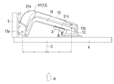
- the connecting bar 3 is attached to the door 4 side of the main arm 13. Further, in a front view (shown by a white arrow A in FIG. 9) in a state where the door 4 is in the closed position, the center B ′ in the width direction of the mounting portion 31 d and the center B in the width direction of the connecting bar 3 are mainly It is arranged closer to the second shaft 13b than the center C between the first shaft 13a of the arm 13 and the second shaft 13b of the main arm 13. In this embodiment, the entire mounting portion 31d and the entire connecting bar 3 are disposed closer to the second shaft 13b side than the center C. As shown in FIG. 8, the connecting bar 3 is located forward of the first link 14 and the second link 15 in the opening direction from the closed position to the opened position of the door 4, and the connecting bar 3 is the first link. 14 and the second link 15 are not interfered with.
- the configuration of the door opening / closing device 1 of this embodiment has been described above.
- the door opening / closing device 1 of the present embodiment has the following effects.
- the main arm 13 has a bent portion 31a, and the main arm 13 approaches the door 4 as it approaches the second shaft 13b. Since the connecting bar 3 is arranged on the door 4 side of the main arm 13 and on the second shaft 13b side, the connecting bar 3 can be brought close to the back surface of the door 4. Therefore, the storage space of the main body 5 can be widened.
- the connecting bar 3 is arranged close to the second shaft 13b, it is possible to prevent the shelf 5b from interfering with the connecting bar 3 even if the shelf 5b is attached to the side plate 5a of the main body 5 as shown in FIG. It can be prevented.
- the strength of the door opening / closing device 1 can be ensured and the door opening / closing can be performed.
- the device 1 can be made compact.
- the main arm 13 has a metal arm body 31 having a U-shaped cross section and a metal assist arm 32 having a U-shaped cross section that is fastened to the arm body 31, and is formed in a tubular shape having a quadrangular cross section. Therefore, the strength of the main arm 13 can be secured.
- the main arm 13 is provided with the finger pinch prevention cover 41 that reduces or eliminates the gap (the gap in the axial direction and the axial gaps ⁇ 1 and ⁇ 2) between the main arm 13 and the first link 14, so that these gaps are provided. It can prevent fingers from being caught. The same applies to the gap between the main arm 13 and the second link 15.
- the door opening / closing device is attached to the side plate of the main body to open / close the door left / right, but the door opening / closing device may be attached to the upper plate or the lower plate of the main body to open / close the door vertically.
- the connecting bars are attached to the pair of hinges, but the connecting bars can be attached to three or more hinges.
Landscapes
- Engineering & Computer Science (AREA)
- Mechanical Engineering (AREA)
- Civil Engineering (AREA)
- Structural Engineering (AREA)
- Hinges (AREA)
Abstract
本体の収納空間を広くすることができる扉開閉装置を提供する。 扉開閉装置(1)は、少なくとも2つのヒンジ(2a,2b)と、少なくとも2つのヒンジ(2a,2b)に連結される連結バー(3)と、を備える。各ヒンジ(2a,2b)は、本体側部材(11)と、扉側部材(12)と、主アーム(13)と、第1リンク(14)と、第2リンク(15)と、を備え、扉(4)を閉じ位置と開き位置との間で平行移動させる。主アーム(13)が屈曲部(31a)を有する。連結バー(3)が主アーム(13)の扉(4)側に取り付けられると共に、扉(4)が閉じ位置にある状態の扉(4)の正面視(A)において、連結バー(3)の幅方向の中心(B)が、主アーム(13)の第1軸(13a)と第2軸(13b)との間の中心(C)よりも第2軸(13b)側に配置される。
Description
本発明は、扉を閉じ位置と開き位置との間で平行移動させる扉開閉装置及びヒンジに関する。
出願人は、この種の扉開閉装置として、図11に示す扉開閉装置を提案している(特許文献1参照)。この扉開閉装置は、一対のヒンジ51a,51bと、一対のヒンジ51a,51bに連結される連結バー52と、を備える。
図12に示すように、各ヒンジ51a,51bは、本体53の内面に取り付けられる本体側部材55と、扉54の背面に取り付けられる扉側部材56と、本体側部材55と扉側部材56に回転可能に連結される主アーム58と、本体側部材55と扉側部材56に回転可能に連結される第1リンク57と、本体側部材55と扉側部材56に回転可能に連結される第2リンク59と、を備える。本体側部材55に対する主アーム58、第1リンク57及び第2リンク59の回転中心である3つの第1軸58a,57a,59aは、軸方向視において三角形の頂点に配置される。同様に、扉側部材56に対する主アーム58、第1リンク57及び第2リンク59の回転中心である3つの第2軸58b,57b,59bは、軸方向視において三角形の頂点に配置される。
本体側部材55、扉側部材56、主アーム58及び第1リンク57は、機構学上の平行リンク機構(平行クランク機構とも呼ばれる)を構成する。このため、扉54が閉じ位置と開き位置との間を平行移動する。ただし、本体側部材55、扉側部材56、主アーム58及び第1リンク57だけだと、扉54の開閉に伴って思案点が生じることがあり、機構が不安定になる。このため、第2リンク59を付加し、機構が不安定になるのを防止している。
図12(b)に示すように、主アーム58は、屈曲部58cを有する。扉54の開き位置において、主アーム58が本体53に干渉したり、図示しない隣の扉に干渉したりするのを防止するためである。
図11に示すように、一対のヒンジ51a,51bの主アーム58には、連結バー52が連結される。扉54が重くても、一対のヒンジ51a,51bを連動させ、扉54を安定的に開閉するためである。
しかし、図11に示すように、従来の扉開閉装置においては、連結バー52が主アーム58の本体53側に、かつ主アーム58の屈曲部58cの近傍に取り付けられる。連結バー52は、本体53の上から下まで通っているので、連結バー52が収納の邪魔になり、本体53の収納空間が狭くなるという課題がある。
本発明は、上記の課題に鑑みてなされたもので、本体の収納空間を広くすることができる扉開閉装置を提供することを目的とする。
上記課題を解決するために、本発明の一態様は、少なくとも2つのヒンジと、前記少なくとも2つのヒンジに連結される連結バーと、を備え、各ヒンジは、本体の内面に取り付けられる本体側部材と、扉の背面に取り付けられる扉側部材と、前記本体側部材と前記扉側部材に回転可能に連結される主アームと、前記本体側部材と前記扉側部材に回転可能に連結される第1リンクと、前記本体側部材と前記扉側部材に回転可能に連結される第2リンクと、を有し、前記本体側部材に対する前記主アーム、前記第1リンク及び前記第2リンクの回転の中心である3つの第1軸が軸方向視において三角形の頂点に配置され、前記扉側部材に対する前記主アーム、前記第1リンク及び前記第2リンクの回転の中心である3つの第2軸が前記軸方向視において三角形の頂点に配置され、前記主アームが屈曲部を有し、前記扉を閉じ位置と開き位置との間で平行移動させる扉開閉装置において、前記連結バーが前記主アームの前記扉側に取り付けられると共に、前記扉が閉じ位置にある状態の前記扉の正面視において、前記連結バーの幅方向の中心が、前記主アームの前記第1軸と前記主アームの前記第2軸との間の中心よりも前記第2軸側に配置される扉開閉装置である。
本発明の他の態様は、本体の内面に取り付けられる本体側部材と、扉の背面に取り付けられる扉側部材と、前記本体側部材と前記扉側部材に回転可能に連結される主アームと、前記本体側部材と前記扉側部材に回転可能に連結される第1リンクと、前記本体側部材と前記扉側部材に回転可能に連結される第2リンクと、を有し、前記本体側部材に対する前記主アーム、前記第1リンク及び前記第2リンクの回転の中心である3つの第1軸が軸方向視において三角形の頂点に配置され、前記扉側部材に対する前記主アーム、前記第1リンク及び前記第2リンクの回転の中心である3つの第2軸が前記軸方向視において三角形の頂点に配置され、前記主アームが屈曲部を有し、前記扉を閉じ位置と開き位置との間で平行移動させるヒンジにおいて、連結バーが取り付けられる前記主アームの取付け部が、前記主アームの前記扉側に配置されると共に、前記扉が閉じ位置にある状態の前記扉の正面視において、前記取付け部の幅方向の中心が、前記主アームの前記第1軸と前記主アームの前記第2軸との間の中心よりも前記第2軸側に配置されるヒンジである。
本発明によれば、連結バーを閉じ位置にある扉の背面に近づけることができる。このため、本体の収納空間を広くすることができる。
以下、添付図面に基づいて、本発明の実施形態の扉開閉装置を詳細に説明する。ただし、本発明の扉開閉装置は種々の形態で具体化することができ、本明細書に記載される実施形態に限定されるものではない。本実施形態は、明細書の開示を十分にすることによって、当業者が発明の範囲を十分に理解できるようにする意図をもって提供されるものである。
図1は、本発明の一実施形態の扉開閉装置1を使用したキャビネットの正面側斜視図(扉4を2点鎖線で示す)であり、図2はキャビネットの背面側斜視図(本体5の一部を破断線で示す)である。なお、以下では、説明の便宜上、扉4を正面視したときの方向、すなわち図に示す前後、上下、左右の各方向を用いて扉開閉装置1の構成を説明する。もちろん、扉開閉装置1の配置は、これに限られるものではない。
図1(a)は扉4の閉じ位置、図1(b)は扉4の中間位置、図1(c)は扉4の開き位置を示す。2aは上側のヒンジ、2bは下側のヒンジ、3はヒンジ2aとヒンジ2bを連結する連結バーである。扉開閉装置1は、一対のヒンジ2a,2bと、一対のヒンジ2a,2bに連結される連結バー3と、を備える。扉4を図1(a)に示す閉じ位置から手前に引き出すと、扉4が平行を保ちながら回転運動し、図1(b)に示す中間位置(前方への最大持ち出し位置)を通過し、図1(c)に示す開き位置まで開く。開き位置では、本体5の間口の全体が開く。
逆に、扉4を図1(c)に示す開き位置から手前に引き出すと、扉4が平行を保ちながら回転運動し、図1(b)に示す中間位置を通過し、図1(a)に示す閉じ位置まで閉まる。ヒンジ2a,2bには、後述するキャッチ機構とダンパ機構とが組み込まれる。扉4は閉じ位置の手前において、キャッチ機構によって自動的に閉じるようになると共に、ダンパ機構によってソフトに閉じ位置まで閉まるようになる。
ヒンジ2aは、本体5の側板5aの内面に取り付けられる本体側部材11と、扉4の背面に取り付けられる扉側部材12と、本体側部材11と扉側部材12に回転可能に連結される主アーム13と、本体側部材11と扉側部材12に回転可能に連結される第1リンク14と、本体側部材11と扉側部材12に回転可能に連結される第2リンク15と、を備える。主アーム13、第1リンク14及び第2リンク15は、屈曲部を有し、への字状に折れ曲がっている。図2(c)に示すように、扉4の開き位置において、本体5の側板5aと干渉したり、図示しない隣の扉と干渉したりするのを防止するためである。
ヒンジ2aとヒンジ2bとは、同一であるか又は天地対称に構成される。以下では、ヒンジ2aの構成のみを説明し、ヒンジ2bについてはその説明を省略する。
図3(a)は、本体5側から見たヒンジ2aの斜視図を示し、図3(b)は、扉4側から見たヒンジ2aの斜視図を示す。第1リンク14は、主アーム13の軸方向(図3(a)の上下方向)の一方側(上側)に主アーム13からずれて配置される。第2リンク15は、主アーム13の軸方向(上下方向)の他方側(下側)に主アーム13からずれて配置される。
図4は、ヒンジの分解斜視図を示す。11は本体側部材、12は扉側部材、13は主アーム、14は第1リンク、15は第2リンクである。
まず、扉開閉装置1のリンク機構を説明する。主アーム13の一端部は、本体側部材11に第1軸13aを中心に回転可能に連結される。主アーム13の他端部は、扉側部材12に第2軸13bを中心に回転可能に連結される。第1リンク14の一端部は、本体側部材11に第1軸14aを中心に回転可能に連結される。第1リンク14の他端部は、扉側部材12に第2軸14bを中心に回転可能に連結される。同様に、第2リンク15の一端部は、本体側部材11に第1軸15aを中心に回転可能に連結される。第2リンク15の他端部は、扉側部材12に第2軸15bを中心に回転可能に連結される。
主アーム13の第1軸13aと第2軸13bとのピッチ、第1リンク14の第1軸14aと第2軸14bとのピッチ、及び第2リンク15の第1軸15aと第2軸15bとのピッチは、互いに等しい。3つの第1軸13a,14a,15aは、軸方向視において、三角形の頂点に配置される。3つの第2軸13b,14b,15bも、軸方向視において、三角形の頂点に配置される。図8に示すように、扉4が開閉する際、第1軸13a,14a,15aによって構成される三角形t1(図8(a)参照)と、第2軸13b,14b,15bによって構成される三角形t2(図8(a)参照)とは、平行を保ち、扉4が閉じ位置と開き位置との間を平行移動する。
次に、扉開閉装置1の各部の構成を説明する。図4に示すように、本体側部材11は、ねじ等の締結部材によって本体5に固定されるプレート21と、ねじ等の締結部材によってプレート21に前後位置を調節可能に固定されるブラケット22と、を備える。ブラケット22は、断面コ字状である。ブラケット22の互いに対向する一対の側板22a,22bがプレート21のスリット21aから突出する。側板22aと側板22bには、主アーム13の第1軸13aが挿入される穴が形成される。側板22aには、第1リンク14の第1軸14aが挿入される穴が形成される。側板22bには、第2リンク15の第1軸15aが挿入される穴が形成される。主アーム13は、一対の側板22a,22bの間に配置される。第1リンク14と第2リンク15は、一対の側板22a,22bの軸方向の外側に配置される。
プレート21に対するブラケット22の前後位置を調節することで、扉4の前後位置を調節できる。調節後、本体側部材11には、座金カバー23(図7(a)参照)が取り付けられる。
図4に示すように、扉側部材12は、ねじ等の締結部材によって扉4に固定されるプレート24と、ねじ等の締結部材によってプレート24に左右位置及び上下位置を調節可能に固定されるブラケット25と、ねじ等の締結部材によってブラケット25に傾き調節可能に固定される角度調節プレート26と、ねじ等の締結部材によって角度調節プレート26に固定されるカム27と、を備える。
ブラケット25、角度調節プレート26及びカム27は、いずれも断面コ字状に形成される。角度調節プレート26の側板26aと側板26bには、主アーム13の第2軸13bが挿入される穴が形成される。側板26aには、第1リンク14の第2軸14bが挿入される穴が形成される。側板26bには、第2リンク15の第2軸15bが挿入される穴が形成される。主アーム13は、角度調節プレート26の一対の側板26a,26bの間に配置される。第1リンク14と第2リンク15は、ブラケット25の一対の側板の軸方向の外側に配置される。
プレート24に対するブラケット25の左右位置及び上下位置を調節することで、扉4の左右位置及び上下位置を調節できる。ブラケット25に対する角度調節プレート26の傾きを調節することで、扉4の傾きを調節できる。調節後、扉側部材12には、座金カバー28(図7(a)参照)が取り付けられる。
図4に示すように、主アーム13は、アーム本体31と、アシストアーム32と、キャッチ機構33と、ダンパ機構34と、を備える。
図5に示すように、アーム本体31は、への字状であり、屈曲部31aを境にして、直線状の短辺部31cと、直線状の長辺部31bと、を有する。アーム本体31の長辺部31bは、断面コ字状であり、対向する一対の側板31b1と、一対の側板31b1を連結する連結板31b2と、を有する。長辺部31bの一対の側板31b1には、連結バー3が取り付けられる取付け部31dが一体に形成される。アーム本体31は、金属板をプレスして製造される。
図5に示すように、アシストアーム32は、断面コ字状であり、対向する一対の側板32aと、一対の側板32aを連結する連結板32bと、を有する。アシストアーム32は、金属板をプレスして製造される。アシストアーム32をアーム本体31の側板31b1間に差し込むことで、主アーム13が断面四角形の筒状に形成される。
図4に示すように、アーム本体31の短辺部31cの一対の側板間には、略L字状の樹脂製のスペーサ36が差し込まれる。アシストアーム32とスペーサ36は、ねじによってアーム本体31に固定される。アシストアーム32とスペーサ36は、主アーム13の強度を向上させる。
図7(a)に示すように、スペーサ36には、ダンパ機構34が挿入される穴36aが形成される。ダンパ機構34は、リニアダンパ38と、ダンパホルダ37と、を備える。ダンパホルダ37は、有底筒状である。ダンパホルダ37には、リニアダンパ38が収容される。本体側部材11には、ダンパストッパ39が取り付けられる。扉4が閉じ位置近傍まで閉まると、ダンパホルダ37がダンパストッパ39に当たり、ダンパ力が発生する。
図4に示すように、アーム本体31とアシストアーム32との間の筒状の空間には、キャッチ機構33が組み込まれる。キャッチ機構33は、圧縮ばね41と、ばねケース42と、ローラ43と、を備える。図7(a)(b)に示すように、ばねケース42は、主アーム13に長さ方向に移動可能に設けられる。ばねケース42には、ローラ43が回転可能に設けられる。圧縮ばね41は、ローラ43を扉側部材12のカム27に付勢する。図7(a)に示すように、扉4が閉じ位置近傍まで閉まると、ローラ43がカム27の凹部に嵌まり、扉4が自動的に閉まるようになる。扉4が開き、ローラ43がカム27の円弧面に当接すると、扉4の任意の開き角が維持される。
図4に示すように、第1リンク14は、への字状であり、屈曲部14cを挟んで、直線状の短辺部14eと、直線状の長辺部14dと、を有する。第1リンク14は、板状である。第2リンク15も、への字状であり、屈曲部15cを挟んで、直線状の短辺部15eと、直線状の長辺部15dと、を有する。第2リンク15も、板状である。
指挟み防止カバー41は、への字状であり、上カバー41aと、下カバー41bと、を備える。上カバー41a及び下カバー41bそれぞれは、主アーム13と同様に、屈曲部を境にして、直線状の長辺部と、直線状の短辺部と、を有する。上カバー41aは、主アーム13の上部に取り付けられる。下カバー41bは、主アーム13の下部に取り付けられる。上カバー41aと下カバー41bは、主アーム13を包み込む。上カバー41aと下カバー41bには、第1軸13aと第2軸13bが貫通する穴42a,42bが形成される。43a,43bはカラーである。上カバー41aと下カバー41bそれぞれの幅(長さ方向と直交する方向の幅)は、主アーム13の幅よりも広い。
図8に示すように、指挟み防止カバー41は、軸方向視における主アーム13と第1リンク14との間の隙間を無くし、かつ軸方向視における主アーム13と第2リンク15との間の隙間を無くす。扉4の閉じ位置から開き位置までの間ずっと、軸方向視における指挟み防止カバー41と第1リンク14との間に隙間が発生することが無く、軸方向視における指挟み防止カバー41と第2リンク15との間に隙間が発生することが無い。
また、図6(b)(d)に示すように、指挟み防止カバー41は、主アーム13と第1リンク14との間の軸方向隙間を少なくし又は無くし、かつ主アーム13と第2リンク15との間の軸方向隙間を少なくし又は無くす。指挟み防止カバー41と第1リンク14との間の軸方向隙間δ1及び指挟み防止カバー41と第2リンク15との間の軸方向隙間δ2は、例えば0mm以上2mm以下である。
図1に示すように、上下一対のヒンジ2a,2bには、ねじ等の締結部材によって上下方向に延びる板状の連結バー3が取り付けられる。図9に示すように、連結バー3は、主アーム13の取付け部31dに取り付けられる。連結バー3の取付け方法は、特に限定されるものではない。例えば、取付け部31dの4隅にねじを貫通させ、ねじに四角ナットを螺合させ、連結バー3の溝を四角ナットに合わせて挿入し、当該ねじを締めることで、連結バー3を取付け部31dに取り付けることができる。
取付け部31dは、主アーム13の扉4側に配置される。連結バー3は、主アーム13の扉4側に取り付けられる。また、扉4が閉じ位置にある状態の正面視(図9の白抜きの矢印Aで示す)において、取付け部31dの幅方向の中心B´及び連結バー3の幅方向の中心Bは、主アーム13の第1軸13aと主アーム13の第2軸13bとの間の中心Cよりも第2軸13b側に配置される。この実施形態では、取付け部31dの全体及び連結バー3の全体が中心Cよりも第2軸13b側に配置される。図8に示すように、扉4の閉じ位置から開き位置までの間ずっと、連結バー3は第1リンク14及び第2リンク15よりも開き方向の前方に位置し、連結バー3は第1リンク14及び第2リンク15に干渉することがない。
以上に本実施形態の扉開閉装置1の構成を説明した。本実施形態の扉開閉装置1によれば、以下の効果を有する。
主アーム13は屈曲部31aを有し、主アーム13は第2軸13bに近づくにつれて扉4に近づく。連結バー3を主アーム13の扉4側にかつ第2軸13b側に配置するので、連結バー3を扉4の背面に近づけることができる。このため、本体5の収納空間を広くすることができる。
また、連結バー3を第2軸13bに近づけて配置するので、例えば、図10に示すように、本体5の側板5aに棚5bを取り付けても、棚5bが連結バー3に干渉するのを防止できる。
第1リンク14を主アーム13の軸方向の一方側に配置し、第2リンク15を主アーム13の軸方向の他方側に配置するので、扉開閉装置1の強度を確保できると共に、扉開閉装置1をコンパクトにすることができる。
主アーム13が、断面コ字状の金属製のアーム本体31と、アーム本体31に締結される断面コ字状の金属製のアシストアーム32と、を有して、断面四角形の筒状に形成されるので、主アーム13の強度を確保することができる。
主アーム13に、主アーム13と第1リンク14との間の隙間(軸方向視における隙間及び軸方向隙間δ1,δ2)を小さくし又は無くす指挟み防止カバー41を取り付けるので、これらの隙間に指を挟むのを防止できる。主アーム13と第2リンク15との間の隙間についても同様である。
なお、本発明は、上記実施形態に具現化されるのに限られることはなく、本発明の要旨を変更しない範囲で様々な実施形態に具現化可能である。
上記実施形態では、扉開閉装置を本体の側板に取り付け、扉を左右に開閉しているが、扉開閉装置を本体の上板又は下板に取り付け、扉を上下に開閉することもできる。
上記実施形態では、一対のヒンジに連結バーを取り付けているが、3つ以上のヒンジに連結バーを取り付けることもできる。
上記実施形態では、軸方向視において指挟み防止カバーと第1リンクとの間の隙間が存在しないが、指を挟まない程度の隙間があってもよい。軸方向視における指挟み防止カバーと第2リンクとの間の隙間も同様である。
本明細書は、2018年10月23日出願の特願2018-198999に基づく。この内容はすべてここに含めておく。
1…扉開閉装置
2a,2b…ヒンジ
3…連結バー
4…扉
5…本体
11…本体側部材
12…扉側部材
13…主アーム
13a…主アームの第1軸
13b…主アームの第2軸
14…第1リンク
14a…第1リンクの第1軸
14b…第1リンクの第2軸
15…第2リンク
15a…第2リンクの第1軸
15b…第2リンクの第2軸
31…アーム本体
31a…主アームの屈曲部
32…アシストアーム
41…指挟み防止カバー
A…扉の正面視
B…連結バーの幅方向の中心
C…主アームの第1軸と第2軸との間の中心
2a,2b…ヒンジ
3…連結バー
4…扉
5…本体
11…本体側部材
12…扉側部材
13…主アーム
13a…主アームの第1軸
13b…主アームの第2軸
14…第1リンク
14a…第1リンクの第1軸
14b…第1リンクの第2軸
15…第2リンク
15a…第2リンクの第1軸
15b…第2リンクの第2軸
31…アーム本体
31a…主アームの屈曲部
32…アシストアーム
41…指挟み防止カバー
A…扉の正面視
B…連結バーの幅方向の中心
C…主アームの第1軸と第2軸との間の中心
Claims (6)
- 少なくとも2つのヒンジと、前記少なくとも2つのヒンジに連結される連結バーと、を備え、
各ヒンジは、本体の内面に取り付けられる本体側部材と、扉の背面に取り付けられる扉側部材と、前記本体側部材と前記扉側部材に回転可能に連結される主アームと、前記本体側部材と前記扉側部材に回転可能に連結される第1リンクと、前記本体側部材と前記扉側部材に回転可能に連結される第2リンクと、を有し、
前記本体側部材に対する前記主アーム、前記第1リンク及び前記第2リンクの回転の中心である3つの第1軸が軸方向視において三角形の頂点に配置され、
前記扉側部材に対する前記主アーム、前記第1リンク及び前記第2リンクの回転の中心である3つの第2軸が前記軸方向視において三角形の頂点に配置され、
前記主アームが屈曲部を有し、
前記扉を閉じ位置と開き位置との間で平行移動させる扉開閉装置において、
前記連結バーが前記主アームの前記扉側に取り付けられると共に、前記扉が閉じ位置にある状態の前記扉の正面視において、前記連結バーの幅方向の中心が、前記主アームの前記第1軸と前記主アームの前記第2軸との間の中心よりも前記第2軸側に配置される扉開閉装置。 - 前記第1リンクが前記主アームの前記軸方向の一方側に前記主アームからずれて配置され、
前記第2リンクが前記主アームの前記軸方向の他方側に前記主アームからずれて配置されることを特徴とする請求項1に記載の扉開閉装置。 - 前記主アームは、断面コ字状のアーム本体と、前記アーム本体に締結される断面コ字状のアシストアームと、を有して、断面四角形の筒状に形成されることを特徴とする請求項1又は2に記載の扉開閉装置。
- 前記主アームには、前記軸方向視における前記主アームと前記第1リンクとの間の隙間、及び前記軸方向視における前記主アームと前記第2リンクとの間の隙間を小さくし又は無くす指挟み防止カバーが取り付けられることを特徴とする請求項2に記載の扉開閉装置。
- 前記主アームには、前記主アームと前記第1リンクとの間の軸方向隙間、及び前記主アームと前記第2リンクとの間の軸方向隙間を小さくし又は無くすように、指挟み防止カバーが取り付けられることを特徴とする請求項2又は4に記載の扉開閉装置。
- 本体の内面に取り付けられる本体側部材と、扉の背面に取り付けられる扉側部材と、前記本体側部材と前記扉側部材に回転可能に連結される主アームと、前記本体側部材と前記扉側部材に回転可能に連結される第1リンクと、前記本体側部材と前記扉側部材に回転可能に連結される第2リンクと、を有し、
前記本体側部材に対する前記主アーム、前記第1リンク及び前記第2リンクの回転の中心である3つの第1軸が軸方向視において三角形の頂点に配置され、
前記扉側部材に対する前記主アーム、前記第1リンク及び前記第2リンクの回転の中心である3つの第2軸が前記軸方向視において三角形の頂点に配置され、
前記主アームが屈曲部を有し、
前記扉を閉じ位置と開き位置との間で平行移動させるヒンジにおいて、
連結バーが取り付けられる前記主アームの取付け部が、前記主アームの前記扉側に配置されると共に、前記扉が閉じ位置にある状態の前記扉の正面視において、前記取付け部の幅方向の中心が、前記主アームの前記第1軸と前記主アームの前記第2軸との間の中心よりも前記第2軸側に配置されるヒンジ。
Priority Applications (4)
| Application Number | Priority Date | Filing Date | Title |
|---|---|---|---|
| EP19876245.2A EP3872287B1 (en) | 2018-10-23 | 2019-10-04 | Door opening/closing device and hinge |
| JP2020507128A JP6851704B2 (ja) | 2018-10-23 | 2019-10-04 | 扉開閉装置及びヒンジ |
| US17/288,337 US11384581B2 (en) | 2018-10-23 | 2019-10-04 | Door opening/closing apparatus and hinge |
| CN201980065801.7A CN112840095B (zh) | 2018-10-23 | 2019-10-04 | 门扇开闭装置和合页 |
Applications Claiming Priority (2)
| Application Number | Priority Date | Filing Date | Title |
|---|---|---|---|
| JP2018198999 | 2018-10-23 | ||
| JP2018-198999 | 2018-10-23 |
Publications (1)
| Publication Number | Publication Date |
|---|---|
| WO2020085043A1 true WO2020085043A1 (ja) | 2020-04-30 |
Family
ID=70330966
Family Applications (1)
| Application Number | Title | Priority Date | Filing Date |
|---|---|---|---|
| PCT/JP2019/039266 Ceased WO2020085043A1 (ja) | 2018-10-23 | 2019-10-04 | 扉開閉装置及びヒンジ |
Country Status (5)
| Country | Link |
|---|---|
| US (1) | US11384581B2 (ja) |
| EP (1) | EP3872287B1 (ja) |
| JP (1) | JP6851704B2 (ja) |
| CN (1) | CN112840095B (ja) |
| WO (1) | WO2020085043A1 (ja) |
Families Citing this family (1)
| Publication number | Priority date | Publication date | Assignee | Title |
|---|---|---|---|---|
| US11866978B2 (en) * | 2020-12-01 | 2024-01-09 | Questar Gas Company | Door swing control device and associated method |
Citations (5)
| Publication number | Priority date | Publication date | Assignee | Title |
|---|---|---|---|---|
| JPS6019258Y2 (ja) * | 1979-10-09 | 1985-06-10 | 政雄 村越 | ヒンジ用カバ− |
| JP2010242427A (ja) * | 2009-04-08 | 2010-10-28 | Sugatsune Ind Co Ltd | ヒンジ装置及びヒンジ装置用取付部材 |
| JP2011212090A (ja) * | 2010-03-31 | 2011-10-27 | Daiken Corp | 仏壇 |
| JP5291810B2 (ja) | 2012-01-06 | 2013-09-18 | スガツネ工業株式会社 | スライドヒンジ及び収容装置 |
| JP2018198999A (ja) | 2018-09-26 | 2018-12-20 | 株式会社ユニバーサルエンターテインメント | 遊技機 |
Family Cites Families (20)
| Publication number | Priority date | Publication date | Assignee | Title |
|---|---|---|---|---|
| DE2950857C2 (de) | 1979-12-18 | 1985-02-14 | Team Form Ag, Hinwil | Türbeschlag zur Parallelführung einer Tür |
| JPS6019258A (ja) | 1983-07-13 | 1985-01-31 | Nec Corp | 記憶装置 |
| JPH0411857Y2 (ja) * | 1984-11-02 | 1992-03-24 | ||
| DE19754417C2 (de) * | 1997-12-09 | 2001-07-26 | Lunke Ventra Automotive Gmbh | Tür-Scharnier |
| US6647592B2 (en) * | 2000-12-19 | 2003-11-18 | Daimlerchrysler Corporation | Four bar hinge |
| US6629337B2 (en) * | 2001-11-28 | 2003-10-07 | Edscha Roof Systems Inc. | Double-pivot resistance hinge for motor vehicle door |
| ITMI20021434A1 (it) * | 2002-06-28 | 2003-12-29 | Antonio Giovannetti | Meccanismo per ante a parallelogramma articolato per apertura/chiusura delle stesse |
| JP2004360180A (ja) * | 2003-05-30 | 2004-12-24 | Shimodaira:Kk | 家具扉の開閉装置 |
| US6889404B2 (en) | 2003-07-18 | 2005-05-10 | Shin Zu Shing Co., Ltd. | Height-adjustable hinge for a liquid crystal display |
| US7971320B2 (en) * | 2008-01-11 | 2011-07-05 | GM Global Technology Operations LLC | Door hinge assembly |
| WO2010018683A1 (ja) * | 2008-08-12 | 2010-02-18 | スガツネ工業株式会社 | ヒンジ装置及び収容装置 |
| US8007026B2 (en) * | 2009-06-02 | 2011-08-30 | Ford Global Technologies, Llc | Lockout feature for full open hinge |
| JP5177569B2 (ja) * | 2009-08-27 | 2013-04-03 | キャタピラー エス エー アール エル | ヒンジおよびドア装置 |
| EP2363560B1 (en) * | 2010-03-05 | 2013-01-02 | Parosha Holding B.V. | Door assembly |
| KR20120122428A (ko) * | 2011-04-29 | 2012-11-07 | 탁동호 | 180도 개문이 가능한 가구용 엑스바형 도어 힌지 |
| US9332842B2 (en) * | 2012-03-28 | 2016-05-10 | BIOMéRIEUX, INC. | Sliding hinges and related methods and devices suitable for apparatus for automated evaluation of microorganism growth in test samples |
| US9217269B2 (en) * | 2014-05-02 | 2015-12-22 | GM Global Technology Operations LLC | Hinge assembly |
| CN107429531B (zh) * | 2015-03-16 | 2019-10-01 | 世嘉智尼工业株式会社 | 合叶装置 |
| JP6453280B2 (ja) * | 2016-08-30 | 2019-01-16 | 有限会社新井鉄工 | 扉体開閉装置 |
| US10968671B2 (en) * | 2017-06-02 | 2021-04-06 | Nissan North America, Inc. | Adjustable vehicle hinge assembly |
-
2019
- 2019-10-04 JP JP2020507128A patent/JP6851704B2/ja active Active
- 2019-10-04 CN CN201980065801.7A patent/CN112840095B/zh active Active
- 2019-10-04 WO PCT/JP2019/039266 patent/WO2020085043A1/ja not_active Ceased
- 2019-10-04 EP EP19876245.2A patent/EP3872287B1/en active Active
- 2019-10-04 US US17/288,337 patent/US11384581B2/en active Active
Patent Citations (5)
| Publication number | Priority date | Publication date | Assignee | Title |
|---|---|---|---|---|
| JPS6019258Y2 (ja) * | 1979-10-09 | 1985-06-10 | 政雄 村越 | ヒンジ用カバ− |
| JP2010242427A (ja) * | 2009-04-08 | 2010-10-28 | Sugatsune Ind Co Ltd | ヒンジ装置及びヒンジ装置用取付部材 |
| JP2011212090A (ja) * | 2010-03-31 | 2011-10-27 | Daiken Corp | 仏壇 |
| JP5291810B2 (ja) | 2012-01-06 | 2013-09-18 | スガツネ工業株式会社 | スライドヒンジ及び収容装置 |
| JP2018198999A (ja) | 2018-09-26 | 2018-12-20 | 株式会社ユニバーサルエンターテインメント | 遊技機 |
Non-Patent Citations (1)
| Title |
|---|
| See also references of EP3872287A4 |
Also Published As
| Publication number | Publication date |
|---|---|
| EP3872287A1 (en) | 2021-09-01 |
| US11384581B2 (en) | 2022-07-12 |
| EP3872287B1 (en) | 2024-09-04 |
| US20210381291A1 (en) | 2021-12-09 |
| JPWO2020085043A1 (ja) | 2021-02-15 |
| EP3872287A4 (en) | 2022-08-03 |
| CN112840095B (zh) | 2022-09-09 |
| CN112840095A (zh) | 2021-05-25 |
| JP6851704B2 (ja) | 2021-03-31 |
Similar Documents
| Publication | Publication Date | Title |
|---|---|---|
| CN102112693B (zh) | 铰接装置及收纳装置 | |
| JP4723013B2 (ja) | 位置調節機能付きカップ埋め込み式ヒンジ装置 | |
| JP5004058B2 (ja) | チェックリンク装置 | |
| WO2021039254A1 (ja) | 1軸ヒンジ | |
| JPWO2018216564A1 (ja) | 扉用装置 | |
| US8916757B2 (en) | Lid opening/closing mechanism for keyboard musical instrument | |
| JP6358474B2 (ja) | 車両用ドアのドアチェック機構 | |
| WO2020085043A1 (ja) | 扉開閉装置及びヒンジ | |
| CN206538590U (zh) | 洗衣机 | |
| JP7535766B2 (ja) | ヒンジ | |
| KR102473554B1 (ko) | 문 개폐 구조 | |
| US20070220533A1 (en) | Tray door attachment structure for disk device | |
| JP6570560B2 (ja) | 丁番 | |
| JP7349328B2 (ja) | 扉開閉装置 | |
| JP2005240465A (ja) | 扉体開閉装置 | |
| JP7339173B2 (ja) | 隠し丁番 | |
| JP2020190259A (ja) | ヒンジ装置 | |
| JP2014136862A (ja) | オープンストッパー取付構造 | |
| KR20090090837A (ko) | 도어힌지 | |
| KR102874361B1 (ko) | 개방 각도 조절이 가능한 도어 힌지 | |
| KR100420363B1 (ko) | 전자레인지의 도어 개폐장치 | |
| JP2008241840A (ja) | ピアノの奥屋根固定装置 | |
| KR20240128465A (ko) | 힌지 프레임 커버 및 이를 포함하는 도어 힌지 | |
| HK40092138A (zh) | 铰链装置 | |
| KR0140488Y1 (ko) | 자동차 도어의 첵커구조 |
Legal Events
| Date | Code | Title | Description |
|---|---|---|---|
| ENP | Entry into the national phase |
Ref document number: 2020507128 Country of ref document: JP Kind code of ref document: A |
|
| 121 | Ep: the epo has been informed by wipo that ep was designated in this application |
Ref document number: 19876245 Country of ref document: EP Kind code of ref document: A1 |
|
| NENP | Non-entry into the national phase |
Ref country code: DE |
|
| ENP | Entry into the national phase |
Ref document number: 2019876245 Country of ref document: EP Effective date: 20210525 |