WO2020085194A1 - 傾斜状構造体およびその製造方法 - Google Patents
傾斜状構造体およびその製造方法 Download PDFInfo
- Publication number
- WO2020085194A1 WO2020085194A1 PCT/JP2019/040911 JP2019040911W WO2020085194A1 WO 2020085194 A1 WO2020085194 A1 WO 2020085194A1 JP 2019040911 W JP2019040911 W JP 2019040911W WO 2020085194 A1 WO2020085194 A1 WO 2020085194A1
- Authority
- WO
- WIPO (PCT)
- Prior art keywords
- base material
- layers
- manufacturing
- beads
- inclined structure
- Prior art date
- Legal status (The legal status is an assumption and is not a legal conclusion. Google has not performed a legal analysis and makes no representation as to the accuracy of the status listed.)
- Ceased
Links
Images





Classifications
-
- B—PERFORMING OPERATIONS; TRANSPORTING
- B23—MACHINE TOOLS; METAL-WORKING NOT OTHERWISE PROVIDED FOR
- B23K—SOLDERING OR UNSOLDERING; WELDING; CLADDING OR PLATING BY SOLDERING OR WELDING; CUTTING BY APPLYING HEAT LOCALLY, e.g. FLAME CUTTING; WORKING BY LASER BEAM
- B23K9/00—Arc welding or cutting
- B23K9/04—Welding for other purposes than joining, e.g. built-up welding
- B23K9/042—Built-up welding on planar surfaces
-
- B—PERFORMING OPERATIONS; TRANSPORTING
- B22—CASTING; POWDER METALLURGY
- B22F—WORKING METALLIC POWDER; MANUFACTURE OF ARTICLES FROM METALLIC POWDER; MAKING METALLIC POWDER; APPARATUS OR DEVICES SPECIALLY ADAPTED FOR METALLIC POWDER
- B22F10/00—Additive manufacturing of workpieces or articles from metallic powder
- B22F10/20—Direct sintering or melting
- B22F10/22—Direct deposition of molten metal
-
- B—PERFORMING OPERATIONS; TRANSPORTING
- B22—CASTING; POWDER METALLURGY
- B22F—WORKING METALLIC POWDER; MANUFACTURE OF ARTICLES FROM METALLIC POWDER; MAKING METALLIC POWDER; APPARATUS OR DEVICES SPECIALLY ADAPTED FOR METALLIC POWDER
- B22F10/00—Additive manufacturing of workpieces or articles from metallic powder
- B22F10/20—Direct sintering or melting
- B22F10/28—Powder bed fusion, e.g. selective laser melting [SLM] or electron beam melting [EBM]
-
- B—PERFORMING OPERATIONS; TRANSPORTING
- B22—CASTING; POWDER METALLURGY
- B22F—WORKING METALLIC POWDER; MANUFACTURE OF ARTICLES FROM METALLIC POWDER; MAKING METALLIC POWDER; APPARATUS OR DEVICES SPECIALLY ADAPTED FOR METALLIC POWDER
- B22F10/00—Additive manufacturing of workpieces or articles from metallic powder
- B22F10/30—Process control
- B22F10/38—Process control to achieve specific product aspects, e.g. surface smoothness, density, porosity or hollow structures
-
- B—PERFORMING OPERATIONS; TRANSPORTING
- B23—MACHINE TOOLS; METAL-WORKING NOT OTHERWISE PROVIDED FOR
- B23K—SOLDERING OR UNSOLDERING; WELDING; CLADDING OR PLATING BY SOLDERING OR WELDING; CUTTING BY APPLYING HEAT LOCALLY, e.g. FLAME CUTTING; WORKING BY LASER BEAM
- B23K26/00—Working by laser beam, e.g. welding, cutting or boring
- B23K26/34—Laser welding for purposes other than joining
- B23K26/342—Build-up welding
-
- B—PERFORMING OPERATIONS; TRANSPORTING
- B33—ADDITIVE MANUFACTURING TECHNOLOGY
- B33Y—ADDITIVE MANUFACTURING, i.e. MANUFACTURING OF THREE-DIMENSIONAL [3D] OBJECTS BY ADDITIVE DEPOSITION, ADDITIVE AGGLOMERATION OR ADDITIVE LAYERING, e.g. BY 3D PRINTING, STEREOLITHOGRAPHY OR SELECTIVE LASER SINTERING
- B33Y10/00—Processes of additive manufacturing
-
- B—PERFORMING OPERATIONS; TRANSPORTING
- B33—ADDITIVE MANUFACTURING TECHNOLOGY
- B33Y—ADDITIVE MANUFACTURING, i.e. MANUFACTURING OF THREE-DIMENSIONAL [3D] OBJECTS BY ADDITIVE DEPOSITION, ADDITIVE AGGLOMERATION OR ADDITIVE LAYERING, e.g. BY 3D PRINTING, STEREOLITHOGRAPHY OR SELECTIVE LASER SINTERING
- B33Y80/00—Products made by additive manufacturing
-
- Y—GENERAL TAGGING OF NEW TECHNOLOGICAL DEVELOPMENTS; GENERAL TAGGING OF CROSS-SECTIONAL TECHNOLOGIES SPANNING OVER SEVERAL SECTIONS OF THE IPC; TECHNICAL SUBJECTS COVERED BY FORMER USPC CROSS-REFERENCE ART COLLECTIONS [XRACs] AND DIGESTS
- Y02—TECHNOLOGIES OR APPLICATIONS FOR MITIGATION OR ADAPTATION AGAINST CLIMATE CHANGE
- Y02P—CLIMATE CHANGE MITIGATION TECHNOLOGIES IN THE PRODUCTION OR PROCESSING OF GOODS
- Y02P10/00—Technologies related to metal processing
- Y02P10/25—Process efficiency
Definitions
- the present invention relates to an inclined structure extending obliquely from the surface of a base material and a method for manufacturing the same.
- the inclined structure extending diagonally from the surface of the base material can be manufactured by overlay welding.
- FIG. 5 of Patent Document 1 describes manufacturing an inclined structure by MIG (Metal Inert Gas) welding.
- Patent Document 1 describes that it is possible to manufacture an inclined structure without a support up to an angle of 33 degrees with respect to a vertical line of the surface of the base material (the details of the invention. See paragraph 0022 of the description). In other words, if the angle between the surface of the base material and the inclination direction of the inclined structure is less than 57 degrees, the inclined structure cannot be manufactured without the support.
- the present invention provides a method for manufacturing a tilted structure capable of manufacturing any tilted structure in any tilt direction without a support, and a tilted structure manufactured by the manufacturing method.
- the purpose is to provide.
- the method for manufacturing a tilted structure of the present invention is a method for manufacturing a tilted structure extending obliquely from the surface of a base material, each of which is on the surface of the base material.
- the reference surface that is inclined with respect to the surface of the base material is first formed, and then the plurality of built-up layers are laminated on the reference surface.
- it can be manufactured without a support.
- the slanted structure may have an annular shape that contracts or expands in diameter with increasing distance from the base material.
- the laminating of the plurality of build-up layers on the surface of the base material and the laminating of the plurality of build-up layers on the reference surface of the base portion may be performed by laser metal overlaying. According to this configuration, the amount of heat input to the base material is small, so that the heat affected zone (HAZ) of the base material can be made small. Further, since the overlaying of the overlay layer on the reference surface of the base portion is also performed by laser metal overlaying, the base portion and the protruding portion can be continuously formed.
- each overlay layer is formed by arranging the beads in order from the base metal side. Good.
- each build-up layer is formed by arranging beads in order from the side farther from the base material, when forming the second bead and thereafter, around the molten pool. Spattered powder easily remains between the existing bead and the base material.
- the beads are formed in order from the side of the base material, it is possible to satisfactorily form the second and subsequent beads in each build-up layer.
- each build-up layer may be formed by arranging the beads in order from the reference surface side. According to this configuration, it is possible to form the reference surface having small unevenness.
- the tilted structure of the present invention is a tilted structure extending obliquely from the surface of the base material, wherein the crystal grains formed on the surface of the base material are perpendicular to the surface of the base material.
- a columnar metal base portion along the direction, and a metal protrusion that extends in the diagonal direction from the base portion, and the crystal grain is a columnar metal column along the diagonal direction, characterized in that To do.
- an inclined structure in any inclination direction can be manufactured without a support.
- FIG. 3 is a plan view of a tilted structure manufactured by a manufacturing method according to an embodiment of the present invention and a base material carrying the tilted structure.
- FIG. 2 is a sectional view taken along line II-II of FIG. 1. It is a figure for demonstrating the process of forming the base part in the said manufacturing method. It is a figure for demonstrating the preparation process before forming the protrusion part in the said manufacturing method. It is a figure for demonstrating the process of forming the protrusion part in the said manufacturing method. It is sectional drawing of the inclined structure manufactured by the conventional manufacturing method. It is sectional drawing of the inclined structure manufactured by the manufacturing method of the said embodiment. It is an enlarged photograph after etching the cut surface of the inclined structure manufactured by the conventional manufacturing method.
- the inclined structure 2 extending in the oblique direction D from the surface 11 of the base material 1 is manufactured.
- the base material 1 has a disk shape having a through hole 12 at the center.
- the shape of the base material 1 is not limited to this, and the base material 1 may have any shape (for example, a bowl shape).
- the inclined structure 2 has an annular shape whose diameter decreases as the distance from the base material 1 increases.
- the inclined structure 2 is a tapered peripheral wall. Therefore, the above-mentioned oblique direction D is a direction along the conical surface.
- the inclined structure 2 may be an annular shape whose diameter increases as the distance from the base material 1 increases.
- the inclined structure 2 does not necessarily have to be annular, and may have an inclined plate shape or column shape.
- the inclined structure 2 includes a base portion 3 formed on the surface 11 of the base material 1 and a protruding portion 5 extending from the base portion 3 in an oblique direction D. Both the base portion 3 and the protruding portion 5 are made of metal.
- the cross-sectional shape of the base portion 3 is triangular as shown in FIG. 3, and the cross-sectional shape of the protruding portion 5 is rectangular as shown in FIG.
- the cross-sectional shape of the base portion 3 is not particularly limited as long as the base portion 3 has a reference surface 31 described later.
- the cross-sectional shape of the base portion 3 may be trapezoidal, or may be fan-shaped having the surface 11 of the base material 1 and the reference surface 31 as two sides.
- the cross-sectional shape of the protrusion 4 is not particularly limited, and may be trapezoidal or triangular.
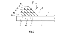
- the base portion 3 is formed by stacking a plurality (six in the illustrated example) of overlay layers 4A to 4F on the surface 11 of the base material 1.
- the uppermost buildup layer 4F is composed of a single bead 41, and the other buildup layers 4A to 4E are the same.
- Each is composed of a plurality of beads 41.
- All beads 41 are concentric with the inclined structure 2. In each of the built-up layers 4A to 4E, the beads 41 are arranged parallel to the surface 11 of the base material 1.
- the base portion 3 has a reference surface 31 that is inclined to the side opposite to the diagonal direction D with respect to the perpendicular of the surface 11 of the base material 1.
- the reference surface 31 is formed by the bead 41 located on the most oblique direction D side in each of the overlay layers 4A to 4F.
- the lamination of the overlay layers 4A to 4F on the surface 11 of the base material 1 is performed by laser metal overlay (LMD).
- LMD laser metal overlay
- the lamination of the overlay layers 4A to 4F on the surface 11 of the base material 1 may be performed by another method such as MIG welding or electron beam welding.
- the welding material and the shield gas are supplied from the nozzle (not shown) toward the surface 11 of the base material 1 or the surface of the overlay layer formed immediately before and laser light is irradiated, thereby generating a molten pool.
- the welding material and the shielding gas are supplied and the laser beam is irradiated while the base material 1 kept horizontally is rotated, and the above-mentioned molten pool becomes the bead 41.
- powder is used as the welding material.
- the welding material may be a wire.
- each of the built-up layers 4A to 4F is sequentially arranged from the reference surface 31 side of the base portion 3 (from the right side to the left side in FIG. 3). ) It is desirable to form the beads 41 side by side. This is because it is possible to form the reference surface 31 having small unevenness and to form the reference surface 31 at an accurate angle with respect to the surface 11 of the base material 1.
- the base material 1 is tilted so that the reference surface 31 of the base portion 3 becomes horizontal at the lowest point, and the LMD is formed.
- the reference surface 31 is smoothed by irradiating only the laser from the nozzle used in the above.
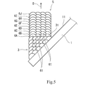
- the protruding portion 5 is formed by stacking a plurality (10 in the illustrated example) of the overlay layers 6A to 6J on the reference surface 31 of the base portion 3.
- the projecting portion 5 since the projecting portion 5 has a rectangular cross-sectional shape as described above, all the built-up layers 6A to 6J each include a plurality of beads 61.
- All of the beads 61 have an annular shape that is concentric with the inclined structure 2. In each of the built-up layers 6A to 6J, the beads 61 are arranged parallel to the reference surface 31 of the base portion 3.
- the build-up layers 6A to 6J are laminated on the reference surface 31 of the base portion 3 by LMD.
- the build-up layers 6A to 6J may be laminated on the reference surface 31 of the base portion 3 by another method such as MIG welding or electron beam welding.
- the welding material and the shield gas are supplied from the nozzle (not shown) toward the reference surface 31 of the base portion 3 or the surface of the overlay layer formed immediately before and the laser light is irradiated, whereby the molten pool is formed. Is generated.
- the welding material and the shielding gas are supplied and the laser light is irradiated while the base material 1 in the tilted state is rotated, and the molten pool becomes the bead 61.
- powder is used as the welding material.
- the welding material may be a wire.
- each of the built-up layers 6A to 6J is bead 61 in order from the base material 1 side (from the right side to the left side in FIG. 5). Are preferably formed side by side.
- the build-up layers 6A to 6J are stacked on the reference surface 31 of the base portion 3, when the beads 61 are formed in order from the side farther from the base material 1, When forming the second and subsequent beads, powder scattered around the molten pool tends to remain between the existing beads and the base material 1.
- the beads 61 are formed in order from the side of the base material 1, it is possible to favorably form the second and subsequent beads in each of the built-up layers 6A to 6J.
- the reference surface 31 that is inclined with respect to the surface 11 of the base material 1 is first formed, and then the plurality of built-up layers 6A to 6J are laminated on the reference surface 31. Even the inclined structure 2 having such an inclination direction can be manufactured without a support.
- FIG. 6 when a plurality of built-up layers are laminated on the surface 11 of the base material 1 while being gradually shifted to manufacture an inclined structure, as shown in FIG.
- the crystal grains in the body form a columnar shape along the stacking direction (direction P perpendicular to the surface 11 of the base material 1). That is, as shown by the alternate long and short dash line in FIG. 6, the crystal grain boundaries are arranged in a direction parallel to the surface 11 of the base material 1. Therefore, the creep strength in the extending direction of the inclined structure is not so high.
- FIG. 6 schematically shows a part of a large number of crystal grain boundaries (this point also applies to FIG. 7 described later).
- FIG. 8 is an enlarged photograph after etching the cut surface of the inclined structure.
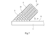
- the crystal grains in the tilted structure 2 are columnar in the base portion 3 along the direction P perpendicular to the surface 11 of the base material 1.
- the protrusion 5 has a columnar shape along the extending direction of the inclined structure 2. That is, in the projecting portion, the crystal grain boundaries are arranged in a direction perpendicular to the oblique direction D, as indicated by a chain line in FIG. 7. Therefore, high creep strength can be obtained in the extending direction of the inclined structure 2.
- the build-up layers 4A to 4F are laminated on the surface 11 of the base material 1 by LMD, the heat input amount to the base material 1 is reduced. Therefore, the heat affected zone (HAZ) of the base material 1 can be reduced. Further, in the present embodiment, since the build-up layers 6A to 6J are also stacked on the reference surface 31 of the base portion 3 by the LMD, the base portion and the protruding portion can be continuously formed.
- each of the built-up layers 4A to 4F forming the base portion 3 does not necessarily have to be formed by arranging the beads 41 in order from the reference surface 31 side of the base portion 3.
- the formation order of the beads 41 may be reversed in each of the overlay layers 4A to 4F.
- each of the built-up layers 6A to 6J forming the protruding portion 5 does not necessarily have to be formed by arranging the beads 61 in order from the base material 1 side. For example, when there are few powders scattered around the molten pool due to welding conditions or the like, first, the beads 61 located on both sides are formed first, and then the beads 61 located inside are formed in each of the overlay layers 6A to 6J. You may.
Landscapes
- Engineering & Computer Science (AREA)
- Chemical & Material Sciences (AREA)
- Manufacturing & Machinery (AREA)
- Materials Engineering (AREA)
- Physics & Mathematics (AREA)
- Optics & Photonics (AREA)
- Plasma & Fusion (AREA)
- Mechanical Engineering (AREA)
- Automation & Control Theory (AREA)
- Laser Beam Processing (AREA)
Abstract
母材の表面から斜め方向に延びる傾斜状構造体を製造する方法であって、母材の表面上に各々が複数のビードからなる複数の肉盛層を積層することによって、母材の表面の垂線に対して斜め方向と反対側に傾斜する基準面を有するベース部を形成する工程と、ベース部の基準面上に各々が複数のビードからなる複数の肉盛層を積層することによって、ベース部から斜め方向に延びる突出部を形成する工程と、を含む。
Description
本発明は、母材の表面から斜め方向に延びる傾斜状構造体およびその製造方法に関する。
母材の表面から斜め方向に延びる傾斜状構造体は、肉盛溶接によって製造することができる。例えば、特許文献1の図5には、MIG(Metal Inert Gas)溶接によって傾斜状構造体を製造することが記載されている。
また、特許文献1には、母材の表面の垂線に対する傾斜状構造体の角度が33度までは支持体なしで傾斜状構造体を製造可能であることが記載されている(発明の詳細な説明の段落0022参照)。換言すれば、母材の表面と傾斜状構造体の傾斜方向との間の角度が57度未満では、支持体なしで傾斜状構造体を製造することができない。
そこで、本発明は、どのような傾斜方向の傾斜状構造体でも支持体なしで製造することができる傾斜状構造体の製造方法を提供すること、およびその製造方法により製造される傾斜状構造体を提供することを目的とする。
前記課題を解決するために、本発明の傾斜状構造体の製造方法は、母材の表面から斜め方向に延びる傾斜状構造体を製造する方法であって、前記母材の表面上に各々が複数のビードからなる複数の肉盛層を積層することによって、前記母材の表面の垂線に対して前記斜め方向と反対側に傾斜する基準面を有するベース部を形成する工程と、前記ベース部の基準面上に各々が複数のビードからなる複数の肉盛層を積層することによって、前記ベース部から前記斜め方向に延びる突出部を形成する工程と、を含む、ことを特徴とする。
上記の構成によれば、母材の表面に対して傾斜する基準面がまず形成され、その後に基準面上に複数の肉盛層が積層されるので、どのような傾斜方向の傾斜状構造体でも支持体なしで製造することができる。
ところで、特許文献1の図5のように複数の肉盛層を少しずつずらしながら母材の表面上に積層して傾斜状構造体を製造した場合には、傾斜状構造体内の結晶粒が積層方向(母材の表面に垂直な方向)に沿った柱状となるため、傾斜状構造体の延在方向におけるクリープ強度がそれほど高くない。これに対し、上記の製造方法で製造された傾斜状構造体では、傾斜状構造体内の結晶粒が突出部では傾斜状構造体の延在方向に沿った柱状となるため、傾斜状構造体の延在方向において高いクリープ強度を得ることができる。
例えば、前記傾斜状構造体は、前記母材から遠ざかるにつれて縮径または拡径する環状であってもよい。
前記母材の表面上への前記複数の肉盛層の積層および前記ベース部の基準面上への前記複数の肉盛層の積層は、レーザ金属肉盛により行われてもよい。この構成によれば、母材への入熱量が小さくなるため、母材の熱影響部(HAZ)を小さくすることができる。また、ベース部の基準面上への肉盛層の積層もレーザ金属肉盛により行われるので、ベース部と突出部とを連続して形成することができる。
前記レーザ金属肉盛では溶接材としてパウダが用いられ、前記基準面上に前記複数の肉盛層を積層する際は、各肉盛層を、前記母材側から順に前記ビードを並べて形成してもよい。基準面上に肉盛層を積層する際に、各肉盛層を、母材から遠い側から順にビードを並べて形成した場合には、第2ビード以降を形成する際に、溶融プールの回りに飛び散ったパウダが既設ビードと母材との間に残存し易い。これに対し、母材側から順にビードを並べて形成すれば、各肉盛層において第2ビード以降も良好に形成することができる。
前記母材の表面上に前記複数の肉盛層を積層する際は、各肉盛層を、前記基準面側から順に前記ビードを並べて形成してもよい。この構成によれば、凹凸の小さい基準面を形成することができる。
また、本発明の傾斜状構造体は、母材の表面から斜め方向に延びる傾斜状構造体であって、前記母材の表面上に形成された、結晶粒が前記母材の表面に垂直な方向に沿った柱状である金属製のベース部と、前記ベース部から前記斜め方向に延びる、結晶粒が前記斜め方向に沿った柱状である金属製の突出部と、を備える、ことを特徴とする。
上記の構成によれば、傾斜状構造体の延在方向において高いクリープ強度を得ることができる。
本発明によれば、どのような傾斜方向の傾斜状構造体でも支持体なしで製造することができる。
本発明の一実施形態に係る製造方法では、図1および図2に示すように、母材1の表面11から斜め方向Dに延びる傾斜状構造体2を製造する。
本実施形態では、母材1が、中心に貫通穴12を有する円盤状である。ただし、母材1の形状はこれに限定されるものではなく、母材1はどのような形状であってもよい(例えば、お椀状など)。
また、本実施形態では、傾斜状構造体2が、母材1から遠ざかるにつれて縮径する環状である。換言すれば、傾斜状構造体2は、テーパー状の周壁である。このため、上述した斜め方向Dは、円錐面に沿った方向である。
ただし、傾斜状構造体2は、母材1から遠ざかるにつれて拡径する環状であってもよい。あるいは、傾斜状構造体2は、必ずしも環状である必要はなく、傾斜する板状または柱状であってもよい。
傾斜状構造体2は、母材1の表面11上に形成されたベース部3と、ベース部3から斜め方向Dに延びる突出部5を含む。これらのベース部3および突出部5は、共に金属製である。
本実施形態では、ベース部3の断面形状が図3に示すように三角形状であり、突出部5の断面形状が図5に示すように矩形状である。ただし、ベース部3の断面形状は、ベース部3が後述する基準面31を有する限り、特に限定されるものではない。例えば、ベース部3の断面形状は、台形状であってもよいし、母材1の表面11および基準面31を二辺とする扇形であってもよい。また、突出部4の断面形状も特に限定されるものではなく、台形状または三角形状であってもよい。
図3に示すように、ベース部3は、母材1の表面11上に複数(図例では6つ)の肉盛層4A~4Fを積層することによって形成される。本実施形態では、上述したようにベース部3の断面形状が三角形状であるため、最も上方に位置する肉盛層4Fは単一のビード41からなり、それ以外の肉盛層4A~4Eはそれぞれ複数のビード41からなる。
全てのビード41は、傾斜状構造体2と同心円状の環状である。肉盛層4A~4Eのそれぞれでは、ビード41が母材1の表面11と平行に並んでいる。
ベース部3は、母材1の表面11の垂線に対して斜め方向Dと反対側に傾斜する基準面31を有する。この基準面31は、肉盛層4A~4Fのそれぞれにおける最も斜め方向D側に位置するビード41により形成される。
本実施形態では、母材1の表面11上への肉盛層4A~4Fの積層がレーザ金属肉盛(LMD)によって行われる。ただし、母材1の表面11上への肉盛層4A~4Fの積層は、MIG溶接や電子ビーム溶接などの他の方法で行われてもよい。
LMDでは、図略のノズルから母材1の表面11または直前に形成された肉盛層の表面に向けて溶接材およびシールドガスが供給されるとともにレーザ光が照射され、これにより溶融プールが生成される。溶接材およびシールドガスの供給ならびにレーザ光の照射は、水平に保たれた母材1が回転されながら行われ、上記の溶融プールがビード41となる。本実施形態では、溶接材としてパウダが用いられる。ただし、溶接材はワイヤであってもよい。
母材1の表面11上に肉盛層4A~4Fを積層する際は、肉盛層4A~4Fのそれぞれを、ベース部3の基準面31側から順に(図3では右側から左側に向かって)ビード41を並べて形成することが望ましい。凹凸の小さい基準面31を形成することができ、かつ、その基準面31を母材1の表面11に対して正確な角度で形成することができるからである。
ベース部3を形成した後は、突出部5を形成する前に、図4に示すように、ベース部3の基準面31が最下点で水平となるように母材1を傾けて、LMDで使用したノズルからレーザのみを照射し、基準面31を平滑化する。
図5に示すように、突出部5は、ベース部3の基準面31上に複数(図例では10)の肉盛層6A~6Jを積層することにより形成される。本実施形態では、上述したように突出部5の断面形状が矩形状であるため、全ての肉盛層6A~6Jがそれぞれ複数のビード61からなる。
全てのビード61は、傾斜状構造体2と同心円状の環状である。肉盛層6A~6Jのそれぞれでは、ビード61がベース部3の基準面31と平行に並んでいる。
本実施形態では、ベース部3の基準面31上への肉盛層6A~6Jの積層がLMDによって行われる。ただし、ベース部3の基準面31上への肉盛層6A~6Jの積層は、MIG溶接や電子ビーム溶接などの他の方法で行われてもよい。
LMDでは、図略のノズルからベース部3の基準面31または直前に形成された肉盛層の表面に向けて溶接材およびシールドガスが供給されるとともにレーザ光が照射され、これにより溶融プールが生成される。溶接材およびシールドガスの供給ならびにレーザ光の照射は、傾けられた状態の母材1が回転されながら行われ、上記の溶融プールがビード61となる。本実施形態では、溶接材としてパウダが用いられる。ただし、溶接材はワイヤであってもよい。
ベース部3の基準面31上に肉盛層6A~6Jを積層する際は、肉盛層6A~6Jのそれぞれを、母材1側から順に(図5では右側から左側に向かって)ビード61を並べて形成することが望ましい。ベース部3の基準面31上に肉盛層6A~6Jを積層する際に、肉盛層6A~6Jのそれぞれを、母材1から遠い側から順にビード61を並べて形成した場合には、第2ビード以降を形成する際に、溶融プールの回りに飛び散ったパウダが既設ビードと母材1との間に残存し易い。これに対し、母材1側から順にビード61を並べて形成すれば、肉盛層6A~6Jのそれぞれにおいて第2ビード以降も良好に形成することができる。
以上説明したような製造方法では、母材1の表面11に対して傾斜する基準面31がまず形成され、その後に基準面31上に複数の肉盛層6A~6Jが積層されるので、どのような傾斜方向の傾斜状構造体2でも支持体なしで製造することができる。
ところで、図6に示すように、複数の肉盛層を少しずつずらしながら母材1の表面11上に積層して傾斜状構造体を製造した場合には、図8に示すように傾斜状構造体内の結晶粒が積層方向(母材1の表面11に垂直な方向P)に沿った柱状となる。つまり、図6中に一点鎖線で示すように、結晶粒界が母材1の表面11と平行な方向に並ぶ。このため、傾斜状構造体の延在方向におけるクリープ強度がそれほど高くない。なお、図6は、多数存在する結晶粒界の一部を概略的に示したものである(この点は、後述する図7も同様)。また、図8は、傾斜状構体の切断面にエッチング処理した後の拡大写真である。
これに対し、本実施形態の製造方法で製造された傾斜状構造体2では、傾斜状構造体2内の結晶粒がベース部3では母材1の表面11に垂直な方向Pに沿った柱状となるが、突出部5では傾斜状構造体2の延在方向に沿った柱状となる。つまり、突出部では、図7中に一点鎖線で示すように、結晶粒界が斜め方向Dと垂直な方向に並ぶ。このため、傾斜状構造体2の延在方向において高いクリープ強度を得ることができる。
また、本実施形態では、母材1の表面11上への肉盛層4A~4Fの積層がLMDにより行われるので、母材1への入熱量が小さくなる。従って、母材1の熱影響部(HAZ)を小さくすることができる。また、本実施形態では、ベース部3の基準面31上への肉盛層6A~6Jの積層もLMDにより行われるので、ベース部と突出部とを連続して形成することができる。
(変形例)
本発明は上述した実施形態に限定されるものではなく、本発明の要旨を逸脱しない範囲で種々の変形が可能である。
本発明は上述した実施形態に限定されるものではなく、本発明の要旨を逸脱しない範囲で種々の変形が可能である。
例えば、ベース部3を構成する肉盛層4A~4Fのそれぞれは、必ずしも、ベース部3の基準面31側から順にビード41を並べて形成される必要はない。例えば、肉盛層4A~4Fのそれぞれにおいて、ビード41の形成順を逆にしてもよい。
また、突出部5を構成する肉盛層6A~6Jのそれぞれは、必ずしも、母材1側から順にビード61を並べて形成される必要はない。例えば、溶接条件などにより溶融プールの回りに飛び散るパウダが少ない場合は、肉盛層6A~6Jのそれぞれにおいて、最初に両側に位置するビード61を形成し、その後に内側に位置するビード61を形成してもよい。
1 母材
11 表面
2 傾斜状構造体
3 ベース部
31 基準面
4A~4F 肉盛層
5 突出部
6A~6J 肉盛層
11 表面
2 傾斜状構造体
3 ベース部
31 基準面
4A~4F 肉盛層
5 突出部
6A~6J 肉盛層
Claims (6)
- 母材の表面から斜め方向に延びる傾斜状構造体を製造する方法であって、
前記母材の表面上に各々が複数のビードからなる複数の肉盛層を積層することによって、前記母材の表面の垂線に対して前記斜め方向と反対側に傾斜する基準面を有するベース部を形成する工程と、
前記ベース部の基準面上に各々が複数のビードからなる複数の肉盛層を積層することによって、前記ベース部から前記斜め方向に延びる突出部を形成する工程と、
を含む、傾斜状構造体の製造方法。 - 前記傾斜状構造体は、前記母材から遠ざかるにつれて縮径または拡径する環状である、請求項1に記載の傾斜状構造体の製造方法。
- 前記母材の表面上への前記複数の肉盛層の積層および前記ベース部の基準面上への前記複数の肉盛層の積層は、レーザ金属肉盛により行われる、請求項1または2に記載の傾斜状構造体の製造方法。
- 前記レーザ金属肉盛では溶接材としてパウダが用いられ、
前記基準面上に前記複数の肉盛層を積層する際は、各肉盛層を、前記母材側から順に前記ビードを並べて形成する、請求項3に記載の傾斜状構造体の製造方法。 - 前記母材の表面上に前記複数の肉盛層を積層する際は、各肉盛層を、前記基準面側から順に前記ビードを並べて形成する、請求項1~4の何れか一項に記載の傾斜状構造体の製造方法。
- 母材の表面から斜め方向に延びる傾斜状構造体であって、
前記母材の表面上に形成された、結晶粒が前記母材の表面に垂直な方向に沿った柱状である金属製のベース部と、
前記ベース部から前記斜め方向に延びる、結晶粒が前記斜め方向に沿った柱状である金属製の突出部と、
を備える、傾斜状構造体。
Priority Applications (2)
| Application Number | Priority Date | Filing Date | Title |
|---|---|---|---|
| EP19875062.2A EP3871819A4 (en) | 2018-10-26 | 2019-10-17 | INCLINED STRUCTURE AND METHOD OF PRODUCTION |
| US17/288,846 US12214445B2 (en) | 2018-10-26 | 2019-10-17 | Inclined structure and method of manufacturing same |
Applications Claiming Priority (2)
| Application Number | Priority Date | Filing Date | Title |
|---|---|---|---|
| JP2018-201394 | 2018-10-26 | ||
| JP2018201394A JP7249127B2 (ja) | 2018-10-26 | 2018-10-26 | 傾斜状構造体およびその製造方法 |
Publications (1)
| Publication Number | Publication Date |
|---|---|
| WO2020085194A1 true WO2020085194A1 (ja) | 2020-04-30 |
Family
ID=70332028
Family Applications (1)
| Application Number | Title | Priority Date | Filing Date |
|---|---|---|---|
| PCT/JP2019/040911 Ceased WO2020085194A1 (ja) | 2018-10-26 | 2019-10-17 | 傾斜状構造体およびその製造方法 |
Country Status (4)
| Country | Link |
|---|---|
| US (1) | US12214445B2 (ja) |
| EP (1) | EP3871819A4 (ja) |
| JP (1) | JP7249127B2 (ja) |
| WO (1) | WO2020085194A1 (ja) |
Cited By (1)
| Publication number | Priority date | Publication date | Assignee | Title |
|---|---|---|---|---|
| EP3725446A1 (en) * | 2019-04-11 | 2020-10-21 | Mitsubishi Heavy Industries Compressor Corporation | Metal laminating and modeling method |
Families Citing this family (2)
| Publication number | Priority date | Publication date | Assignee | Title |
|---|---|---|---|---|
| JP7619435B2 (ja) * | 2021-03-24 | 2025-01-22 | 株式会社ニコン | 造形装置及び造形方法 |
| JP2022163944A (ja) * | 2021-04-15 | 2022-10-27 | 国立大学法人京都大学 | 付加加工装置、付加加工装置の制御方法、および、付加加工装置の制御プログラム |
Citations (4)
| Publication number | Priority date | Publication date | Assignee | Title |
|---|---|---|---|---|
| JPS62599B2 (ja) * | 1982-12-28 | 1987-01-08 | Tokyo Shibaura Electric Co | |
| JPH04336304A (ja) | 1991-01-21 | 1992-11-24 | Gebr Sulzer Ag | 金属製品の製造方法及び製造装置 |
| WO2018079467A1 (ja) * | 2016-10-28 | 2018-05-03 | Ntn株式会社 | 三次元造形装置 |
| JP2018126760A (ja) * | 2017-02-08 | 2018-08-16 | 株式会社神戸製鋼所 | 積層制御装置、積層制御方法及びプログラム |
Family Cites Families (4)
| Publication number | Priority date | Publication date | Assignee | Title |
|---|---|---|---|---|
| JP6114718B2 (ja) | 2014-06-17 | 2017-04-12 | 川崎重工業株式会社 | 軸対称体および軸対称製品の製造方法 |
| EP3243635B1 (en) | 2016-03-25 | 2021-05-05 | Technology Research Association for Future Additive Manufacturing | Three-dimensional lamination shaping device, method for controlling three-dimensional lamination shaping device, and program for controlling three-dimensional lamination shaping device |
| US11453054B2 (en) | 2016-11-28 | 2022-09-27 | Panasonic Intellectual Property Management Co., Ltd. | Method for manufacturing three-dimensional shaped object |
| CN110446581B (zh) * | 2018-03-02 | 2020-11-20 | 三菱电机株式会社 | 附加制造装置及附加制造方法 |
-
2018
- 2018-10-26 JP JP2018201394A patent/JP7249127B2/ja active Active
-
2019
- 2019-10-17 US US17/288,846 patent/US12214445B2/en active Active
- 2019-10-17 WO PCT/JP2019/040911 patent/WO2020085194A1/ja not_active Ceased
- 2019-10-17 EP EP19875062.2A patent/EP3871819A4/en active Pending
Patent Citations (4)
| Publication number | Priority date | Publication date | Assignee | Title |
|---|---|---|---|---|
| JPS62599B2 (ja) * | 1982-12-28 | 1987-01-08 | Tokyo Shibaura Electric Co | |
| JPH04336304A (ja) | 1991-01-21 | 1992-11-24 | Gebr Sulzer Ag | 金属製品の製造方法及び製造装置 |
| WO2018079467A1 (ja) * | 2016-10-28 | 2018-05-03 | Ntn株式会社 | 三次元造形装置 |
| JP2018126760A (ja) * | 2017-02-08 | 2018-08-16 | 株式会社神戸製鋼所 | 積層制御装置、積層制御方法及びプログラム |
Non-Patent Citations (1)
| Title |
|---|
| See also references of EP3871819A4 |
Cited By (2)
| Publication number | Priority date | Publication date | Assignee | Title |
|---|---|---|---|---|
| EP3725446A1 (en) * | 2019-04-11 | 2020-10-21 | Mitsubishi Heavy Industries Compressor Corporation | Metal laminating and modeling method |
| US11400536B2 (en) | 2019-04-11 | 2022-08-02 | Mitsubishi Heavy Industries Compressor Corporation | Metal laminating and modeling method |
Also Published As
| Publication number | Publication date |
|---|---|
| JP7249127B2 (ja) | 2023-03-30 |
| JP2020066040A (ja) | 2020-04-30 |
| US12214445B2 (en) | 2025-02-04 |
| EP3871819A4 (en) | 2022-08-17 |
| EP3871819A1 (en) | 2021-09-01 |
| US20220001491A1 (en) | 2022-01-06 |
Similar Documents
| Publication | Publication Date | Title |
|---|---|---|
| WO2020085194A1 (ja) | 傾斜状構造体およびその製造方法 | |
| US12544857B2 (en) | Welding method and welding apparatus | |
| JP5902400B2 (ja) | レーザ溶接装置、レーザ溶接方法、鋼板積層体の製造方法及び積層体のレーザ溶接による溶接構造 | |
| EP3305459B1 (en) | Laser welding method, laser welding conditions determining method, and laser welding system | |
| JP5985581B2 (ja) | 処理装置及びコリメータ | |
| JP6756191B2 (ja) | 蒸着マスクの製造方法、蒸着マスク製造装置、レーザー用マスクおよび有機半導体素子の製造方法 | |
| JP6006474B2 (ja) | 配線基板、多数個取り配線基板、およびその製造方法 | |
| JP2017150037A (ja) | シャドーマスク、シャドーマスクの製造方法及び表示装置の製造方法 | |
| CN106660175A (zh) | 轴对称体以及轴对称产品的制造方法 | |
| JPWO2017170523A1 (ja) | ロータの製造方法 | |
| JP2019217524A (ja) | レーザ溶接方法および溶接構造体 | |
| KR20190043220A (ko) | 레이저와 금속 분말을 이용한 3차원 형상 제조방법 | |
| US10040251B2 (en) | Layered object, method for manufacturing layered object, and apparatus for manufacturing layered object | |
| WO2016204019A1 (ja) | 成膜マスク及び成膜マスクの製造方法 | |
| JP2019115952A5 (ja) | ||
| EP3563966B1 (en) | Projection forming method | |
| JP2008200749A (ja) | レーザーリペアシステム | |
| JP6400916B2 (ja) | 接合体の製造方法 | |
| JP6660761B2 (ja) | 粒子線治療システムおよびリッジフィルタならびにリッジフィルタの製造方法 | |
| JP2018089110A (ja) | リッジフィルタおよびその製造方法 | |
| JP2006302926A (ja) | レーザスクライブ用シリコン基板及びシリコン基板のダイシング方法 | |
| JP6906652B2 (ja) | 蒸着マスク | |
| JP7185436B2 (ja) | レーザ加工方法 | |
| JP6893691B2 (ja) | 複層脆性材料基板の作製方法および作製システム | |
| JP4665682B2 (ja) | マイクロデバイス用電極の製造方法およびマイクロデバイス用電極 |
Legal Events
| Date | Code | Title | Description |
|---|---|---|---|
| 121 | Ep: the epo has been informed by wipo that ep was designated in this application |
Ref document number: 19875062 Country of ref document: EP Kind code of ref document: A1 |
|
| NENP | Non-entry into the national phase |
Ref country code: DE |
|
| ENP | Entry into the national phase |
Ref document number: 2019875062 Country of ref document: EP Effective date: 20210526 |