WO2020085381A1 - 自動車骨格部材および電気自動車 - Google Patents
自動車骨格部材および電気自動車 Download PDFInfo
- Publication number
- WO2020085381A1 WO2020085381A1 PCT/JP2019/041527 JP2019041527W WO2020085381A1 WO 2020085381 A1 WO2020085381 A1 WO 2020085381A1 JP 2019041527 W JP2019041527 W JP 2019041527W WO 2020085381 A1 WO2020085381 A1 WO 2020085381A1
- Authority
- WO
- WIPO (PCT)
- Prior art keywords
- groove
- top plate
- frame member
- vehicle
- vertical wall
- Prior art date
- Legal status (The legal status is an assumption and is not a legal conclusion. Google has not performed a legal analysis and makes no representation as to the accuracy of the status listed.)
- Ceased
Links
Images


Classifications
-
- B—PERFORMING OPERATIONS; TRANSPORTING
- B62—LAND VEHICLES FOR TRAVELLING OTHERWISE THAN ON RAILS
- B62D—MOTOR VEHICLES; TRAILERS
- B62D21/00—Understructures, i.e. chassis frame on which a vehicle body may be mounted
- B62D21/15—Understructures, i.e. chassis frame on which a vehicle body may be mounted having impact absorbing means, e.g. a frame designed to permanently or temporarily change shape or dimension upon impact with another body
- B62D21/157—Understructures, i.e. chassis frame on which a vehicle body may be mounted having impact absorbing means, e.g. a frame designed to permanently or temporarily change shape or dimension upon impact with another body for side impacts
-
- B—PERFORMING OPERATIONS; TRANSPORTING
- B60—VEHICLES IN GENERAL
- B60R—VEHICLES, VEHICLE FITTINGS, OR VEHICLE PARTS, NOT OTHERWISE PROVIDED FOR
- B60R16/00—Electric or fluid circuits specially adapted for vehicles and not otherwise provided for; Arrangement of elements of electric or fluid circuits specially adapted for vehicles and not otherwise provided for
- B60R16/02—Electric or fluid circuits specially adapted for vehicles and not otherwise provided for; Arrangement of elements of electric or fluid circuits specially adapted for vehicles and not otherwise provided for electric constitutive elements
- B60R16/04—Arrangement of batteries
-
- B—PERFORMING OPERATIONS; TRANSPORTING
- B60—VEHICLES IN GENERAL
- B60R—VEHICLES, VEHICLE FITTINGS, OR VEHICLE PARTS, NOT OTHERWISE PROVIDED FOR
- B60R19/00—Wheel guards; Radiator guards, e.g. grilles; Obstruction removers; Fittings damping bouncing force in collisions
- B60R19/02—Bumpers, i.e. impact receiving or absorbing members for protecting vehicles or fending off blows from other vehicles or objects
- B60R19/18—Bumpers, i.e. impact receiving or absorbing members for protecting vehicles or fending off blows from other vehicles or objects characterised by the cross-section; Means within the bumper to absorb impact
-
- B—PERFORMING OPERATIONS; TRANSPORTING
- B62—LAND VEHICLES FOR TRAVELLING OTHERWISE THAN ON RAILS
- B62D—MOTOR VEHICLES; TRAILERS
- B62D21/00—Understructures, i.e. chassis frame on which a vehicle body may be mounted
- B62D21/15—Understructures, i.e. chassis frame on which a vehicle body may be mounted having impact absorbing means, e.g. a frame designed to permanently or temporarily change shape or dimension upon impact with another body
-
- B—PERFORMING OPERATIONS; TRANSPORTING
- B62—LAND VEHICLES FOR TRAVELLING OTHERWISE THAN ON RAILS
- B62D—MOTOR VEHICLES; TRAILERS
- B62D25/00—Superstructure or monocoque structure sub-units; Parts or details thereof not otherwise provided for
- B62D25/02—Side panels
- B62D25/025—Side sills thereof
-
- B—PERFORMING OPERATIONS; TRANSPORTING
- B60—VEHICLES IN GENERAL
- B60R—VEHICLES, VEHICLE FITTINGS, OR VEHICLE PARTS, NOT OTHERWISE PROVIDED FOR
- B60R19/00—Wheel guards; Radiator guards, e.g. grilles; Obstruction removers; Fittings damping bouncing force in collisions
- B60R19/02—Bumpers, i.e. impact receiving or absorbing members for protecting vehicles or fending off blows from other vehicles or objects
- B60R19/18—Bumpers, i.e. impact receiving or absorbing members for protecting vehicles or fending off blows from other vehicles or objects characterised by the cross-section; Means within the bumper to absorb impact
- B60R2019/1806—Structural beams therefor, e.g. shock-absorbing
- B60R2019/1813—Structural beams therefor, e.g. shock-absorbing made of metal
-
- B—PERFORMING OPERATIONS; TRANSPORTING
- B62—LAND VEHICLES FOR TRAVELLING OTHERWISE THAN ON RAILS
- B62D—MOTOR VEHICLES; TRAILERS
- B62D29/00—Superstructures, understructures, or sub-units thereof, characterised by the material thereof
- B62D29/008—Superstructures, understructures, or sub-units thereof, characterised by the material thereof predominantly of light alloys, e.g. extruded
Definitions
- the present disclosure relates to an automobile frame member that exhibits high energy absorption efficiency in the event of an automobile collision, for example.
- Patent Document 1 discloses that a bulkhead having a substantially U-shaped cross section is provided between a side sill and a cross member.
- the bulkhead of Patent Document 1 is composed of a front surface portion, a rear side surface portion, and a flange, and has recesses in the front surface portion and the rear side surface portion.
- Patent Document 2 discloses a shock absorbing member in which a hollow member is provided with a bellows-shaped deformation promoting means.
- the impact absorbing member of Patent Document 2 converts the bending load into a compressive load in the longitudinal direction by buckling the bellows-shaped deformation promoting means when a bending load due to impact is applied, thereby suppressing the collapse of the cross section.
- Patent Document 3 discloses a metal absorber in which a concave or convex bead is formed on a vertical wall of a hat member.
- Patent Document 1 Since the vehicle body structure of Patent Document 1 is not designed to suppress buckling of the side sill itself, there is room for improvement in terms of improving energy absorption performance by utilizing the material strength.
- the present inventor performed a simulation of the impact absorbing member of Patent Document 2, there are many portions where the plastic deformation is not left in the impact absorbing member, and the viewpoint of improving the energy absorbing performance by utilizing the material strength. So there is room for improvement.
- the absorber of Patent Document 3 is intended to protect the legs of a pedestrian at the time of a collision between a pedestrian and an automobile, and there is room for improvement in terms of improving the energy absorption performance on the vehicle body side.
- the present disclosure has been made in view of the above problems, and an object thereof is to improve the energy absorption efficiency (mass efficiency of absorbed energy) of an automobile frame member.
- an automobile frame member which includes a hat member and a closing plate
- the hat member includes a top plate, two vertical walls, and two flanges.
- the two vertical walls are respectively between the top plate and the flange, the two vertical walls face each other, the two flanges are respectively joined to the closing plate, and the two vertical walls are respectively A plurality of groove portions extending in a direction perpendicular to the longitudinal direction of the hat member, wherein the groove portions include a bottom surface and two side surfaces, the two side surfaces face each other, and the two side surfaces are on both sides of the bottom surface.
- the width a of the groove portion and the depth b of the groove portion in a cross section parallel to the top plate, and the height c of the vertical wall in the direction perpendicular to the top plate are 0.2 ⁇ a / c ⁇ 0. 3 and 0.2 It is set to satisfy the relation of b / c ⁇ 0.3.
- an automobile frame member which includes a hollow member, the hollow member includes a top plate and two vertical walls, and the two vertical walls are respectively the top plate. Adjacent to each other, the two vertical walls face each other, and each of the two vertical walls includes a plurality of groove portions extending in a direction perpendicular to the longitudinal direction of the hollow member, the groove portion having a bottom surface and two side surfaces. The two side surfaces face each other, the two side surfaces are on both sides of the bottom surface, and the width a of the groove portion and the depth b of the groove portion in a cross section parallel to the top plate are perpendicular to the top plate.
- the height c of the vertical wall in the vertical direction is characterized by satisfying the relations of 0.2 ⁇ a / c ⁇ 0.3 and 0.2 ⁇ b / c ⁇ 0.3.
- the energy absorption efficiency of automobile frame members can be improved.
- FIG. 6 is a sectional view taken along the line AA in FIG. 5.
- FIG. 8 is a sectional view taken along line BB in FIG. 7. It is a figure which shows an example (in-plane bending mode) of the deformation mode of a vehicle frame member. It is a figure which shows an example (axial crushing mode) of the deformation mode of a vehicle frame member.
- FIG. 11 is a sectional view taken along line CC of FIG. 10. It is a perspective view showing a schematic structure of a car frame member concerning a 2nd embodiment. It is a figure corresponding to the AA cross section in FIG. 5 of the vehicle frame member which concerns on 2nd Embodiment.
- FIG. 8 is a sectional view taken along line BB in FIG. 7. It is a figure which shows an example (in-plane bending mode) of the deformation mode of a vehicle frame member. It is a figure which shows an example (axial crushing mode) of the deformation mode of a vehicle frame member.
- FIG. 11 is a sectional view taken along line CC of FIG. 10. It is a perspective view showing
- FIG. 6 is a view showing an example of the shape of a groove portion and corresponding to the AA cross section in FIG. 5. It is a figure corresponding to the AA cross section in FIG. 5 of the vehicle frame member which concerns on 3rd Embodiment.
- FIG. 6 is a view corresponding to a cross section taken along the line AA in FIG. 5 of an automobile frame member having grooves in both the first hat member and the second hat member. It is a perspective view showing a schematic structure of a car frame member concerning a 4th embodiment. It is a figure corresponding to the AA cross section in FIG. 5 of the vehicle frame member which concerns on 4th Embodiment. It is a figure which shows the example of a shape of a groove part.
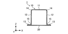
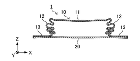
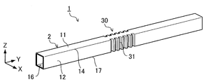
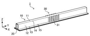
- FIG. 1 is a diagram showing a schematic configuration of an automobile frame member 1 according to the first embodiment.
- the automobile frame member 1 is a member such as a side sill or a bumper beam that receives a bending load.
- the vehicle frame member 1 of the first embodiment has a hat member 10 that is a hat-shaped member in a cross section perpendicular to the member longitudinal direction (Y direction in FIG. 1), and a flat plate that is a bottom plate joined to the hat member 10.
- the X direction is the vehicle height direction and the Y direction is the vehicle length.
- the direction and the Z direction are vehicle width directions.
- the X direction is the vehicle height direction
- the Y direction is the vehicle width direction
- the Z direction is the vehicle length direction.
- the hat member 10 has a top plate 11, two vertical walls 12 connected to the top plate 11, and two flanges 13 connected to the vertical wall 12.
- the two vertical walls 12 are between the top plate 11 and the flange 13, respectively, and the two vertical walls 12 face each other.
- the automobile frame member 1 is configured by joining the two flanges 13 of the hat member 10 and the closing plate 20.
- the hat member 10 is formed of, for example, a steel material having a tensile strength of 440 to 1500 MPa, but the material of the hat member 10 is not particularly limited and may be, for example, an aluminum alloy member or a magnesium alloy member.
- the closing plate 20 is formed of, for example, a steel material having a tensile strength of 440 to 1500 MPa, but the material of the closing plate 20 is not particularly limited, and may be, for example, an aluminum alloy member or a magnesium alloy member.
- the top plate 11 of the hat member 10 may be arranged outside the vehicle or inside the vehicle with respect to the closing plate 20. Particularly in the case of a side sill, it is preferable that the top plate 11 is arranged outside the vehicle with respect to the closing plate 20. This is because if the flange of the hat member is on the outside of the vehicle, the flange interferes with the door and the door does not close. Further, it is preferable to apply the present disclosure to an electric vehicle. This is because the side sill can absorb the shock to prevent damage to the battery arranged inside the side sill. FIG.
- FIG. 3 is a diagram showing the periphery of the side sill 41 in a cross section perpendicular to the vehicle height direction of the electric vehicle 40.
- the closing plate 20 is adjacent to the battery 42 mounted on the floor panel (not shown), and the top plate 11 is the vehicle.
- the top plate 11 is disposed on the vehicle outer side, of the vehicle outer side and the vehicle inner side.
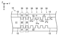
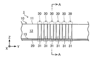
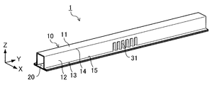
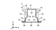
- the hat member 10 As shown in FIGS. 1 and 4 to 6, the hat member 10 according to the first embodiment has a groove portion 31 extending in a direction perpendicular to the member longitudinal direction. From the viewpoint of effectively improving the energy absorption efficiency, the groove portion 31 extends from the ridge line portion 14 to the ridge line portion 15 as shown in FIGS. 1 and 4 to 6, that is, the vehicle-inside end portion of the vertical wall 12. It is preferable that it is formed from to the vehicle outer side end portion.
- the groove 31 is provided on both of the pair of vertical walls 12.
- the method for forming the groove portion 31 is not particularly limited, and for example, the hat member 10 is formed by repeatedly performing pressing after forming the hat member 10 and gradually increasing the depth of the groove portion 31.
- a portion where the groove portion 31 as shown in FIG. 4 is formed is referred to as a “groove forming portion 30”.
- the top plate 11 in the groove forming portion 30 is referred to as a “groove portion top plate 32”
- the vertical wall 12 in the groove forming portion 30 is referred to as a “groove portion vertical wall 33”.
- the flange 13 in the groove forming portion 30 is referred to as "groove flange 34".
- the groove top plate 32 is located in the same plane as the top plate 11 other than the groove forming portion 30, and the groove flange 34 is located in the same plane as the flange 13 other than the groove forming portion 30.
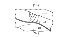
- the groove portion vertical wall 33 of the first embodiment includes a bottom surface 31 a of the groove portion 31 which is a surface parallel to the vertical wall 12 in a portion other than the groove forming portion 30, and a portion other than the groove forming portion 30. It has a pair of flat side surfaces 31b connecting the vertical wall 12 of the part and the bottom surface 31a of the groove 31. That is, the groove portion 31 includes a bottom surface 31a and two side surfaces 31b, and the two side surfaces 31b face each other and are located on both sides of the bottom surface 31a.
- a plurality of groove forming portions 30 are provided at intervals along the member longitudinal direction of the hat member 10. That is, the two vertical walls 12 are provided with a plurality of groove portions 31 along the member longitudinal direction of the hat member 10.
- the region in which the groove forming portion 30 exists is only the central portion in the member longitudinal direction of the hat member 10, but the groove forming portion 30 is, for example, in the entire region in the member longitudinal direction of the hat member 10. It may be provided.
- the vertical wall 12 located between the adjacent groove forming portions 30 has a shape protruding from the bottom surface 31 a of the groove portion 31 due to the plurality of groove forming portions 30 being provided.
- the automobile frame member 1 of the first embodiment is configured as described above.
- a load is partially applied from the Z direction at the time of a collision, and a moment is generated, so that bending deformation occurs.
- the groove portion 31 of the hat member 10 is provided not only on the vertical wall 12 but also on the ridge line portion 14 between the vertical wall 12 and the top plate 11 and between the vertical wall 12 and the flange 13. Since the ridge line portion 15 is provided, the surface rigidity of the top plate 11 is increased and the load required for the deformation of the automobile skeleton member 1 is increased as compared with the case where the groove portions 31 are not provided on the ridge line portions 14 and 15. be able to.
- the groove portion 31 has three planes, that is, the shape having the bottom surface 31a of the groove portion 31 and the two side surfaces 31b, so that the surface rigidity of the top plate 11 can be further increased, and the deformation of the automobile skeletal member 1 can be improved.
- the load required for can be further increased.
- the energy absorption performance can be improved by these actions. Further, since the automobile frame member 1 of the first embodiment does not have a structure in which a reinforcing member is newly added, it is possible to improve mass efficiency regarding energy absorption performance.
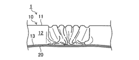
- the out-of-plane bending mode is a mode in which the main deformation is a deformation in which the vertical wall 12 of the hat member 10 is bent in the out-of-plane direction in a cross section perpendicular to the member longitudinal direction.
- the main deformation is deformation in which the vertical wall 12 of the hat member 10 is bent along the member longitudinal direction, and the deformation occurs in the out-of-plane direction in a cross section perpendicular to the member longitudinal direction. This is a mode in which the vertical wall 12 has a small deformation.
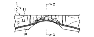
- the axial crush mode is a mode in which the vertical wall 12 of the hat member 10 crushes at short intervals in a cross section perpendicular to the member longitudinal direction, and a bellows-like deformation occurs as a whole.
- the vehicle frame member 1 be deformed in the axial crush mode.
- the width of the groove portion 31 and the depth of the groove portion 31 in the cross section parallel to the top plate 11 of the hat member 10 are defined as “a” and shown in FIG.
- the height of the vertical wall 12 in the direction perpendicular to the top plate 11 of the hat member 10 is defined as "c”.
- the width a of the groove 31 is the distance between the side surfaces 31b of the hat member 10 that face each other in the member longitudinal direction (Y direction).
- the depth b of the groove portion 31 means a distance from the vertical wall 12 to the bottom surface 31 a of the groove portion 31 in a direction (X direction) perpendicular to the member longitudinal direction of the hat member 10 in a cross section parallel to the top plate 11 of the hat member 10.
- the height c of the vertical wall 12 is the length from the flange 13 to the top plate 11 in the direction (Z direction) perpendicular to the member longitudinal direction of the hat member 10. In addition, in the first embodiment, the height c of the vertical wall 12 is equal to the height from the groove flange 34 to the groove top plate 32.
- the width a of the groove portion 31, the depth b of the groove portion 31, and the height c of the vertical wall 12 of the hat member 10 are 0.2. It is preferable to satisfy the relationship of ⁇ a / c ⁇ 0.3 and 0.2 ⁇ b / c ⁇ 0.3. When this numerical range is satisfied, the deformation of the automobile frame member 1 is likely to be in the axial crushing mode, and the load required for the deformation is stably increased from the initial stage of the collision to the latter stage of the collision, as will be shown in Examples described later. Thereby, the energy absorption performance can be further improved.
- the interval d between the adjacent groove portions 31 is preferably 50 mm or less.
- the axial crushing mode is easily deformed, and the energy absorption efficiency can be improved.
- the distance d between the groove portions 31 is 10 mm or more. preferable.
- the angle ⁇ 1 formed by the bottom surface 31a of the groove portion 31 and the side surface 31b of the groove portion 31 is preferably 90 to 95 degrees, and is vertical. More preferable.
- the angle ⁇ 2 formed by the groove vertical wall 33 and the groove flange 34 is 90 to 100 degrees, as shown in FIG. Is more preferable.
- the groove portion 31 does not extend to the ridge line portion 14 of the hat member 10. That is, in the automobile frame member 1 of the second embodiment, one end of the groove portion 31 extends to the vehicle-inside end portion of the vertical wall 12 (ridge line portion 15 in the example of FIG. 14), but the other end of the groove portion 31. Does not extend to the vehicle outer side end of the vertical wall 12 (the ridge line portion 14 in the example of FIG. 14).
- the width a of the groove portion 31, the depth b of the groove portion 31, and the height c of the vertical wall 12 of the hat member 10 are 0.2 ⁇ a / c ⁇ 0.
- FIG. 14 is a diagram showing an example of the shape of the groove portion 31.
- the automobile frame member 1 in the example of FIG. 14 is different from the example of FIG. 13 in that one end of the groove portion 31 extends to the vehicle outer side end portion of the vertical wall 12 (ridge line portion 14 in the example of FIG. 14) while the groove portion The other end of 31 is a structure that does not extend to the vehicle-inside end of the vertical wall 12 (ridge line portion 15 in the example of FIG. 14).
- the above-described automobile frame member 1 having the structure shown in FIG. 13 can improve energy absorption efficiency more than the automobile frame member 1 having the structure shown in FIG.
- the buckling region expands toward the vehicle-inside end of the vertical wall 12 starting from the first buckled portion of the vertical wall 12. For this reason, it is more advantageous in terms of improving energy absorption efficiency that the first buckling portion is on the vehicle exterior side of the vertical wall 12.
- the vehicle interior side of the vertical wall 12 buckles first, the deviation between the extending direction of the groove portion 31 on the vehicle exterior side and the impact input direction becomes large, and the deformation of the shaft crush mode hardly occurs.
- the first buckling area is the area without the groove 31.
- the reason for buckling first without the groove 31 is that the deformation resistance is small without the groove 31.
- the groove portion 31 extends to the vehicle inner side end of the vertical wall 12 (the ridge line portion 15 in the example of FIG. 13), and the vehicle outer side end of the vertical wall 12 (in the example of FIG. 13, No groove 31 is formed in the ridge 14). Therefore, the vehicle frame member 1 of FIG. 13 is likely to buckle near the vehicle outer end (the ridge line portion 14 in the example of FIG. 13) of the vertical wall 12 when an impact load is input.
- the automobile skeleton member 1 having the structure as shown in FIG. 13 can secure a larger area that is deformed in a bellows shape as compared with the automobile skeleton member 1 having the structure as shown in FIG. 14, thereby improving energy absorption efficiency.
- the groove portion 31 is not formed in one of the ridge line portions 14 and 15 of the ridge line portion 15, so that the automobile of the first embodiment
- the hat member 10 is easier to mold than the skeleton member 1. That is, the automobile skeleton member 1 of the second embodiment is a member that can achieve both high energy absorption efficiency and moldability at a high level.
- the groove portion 31 When the groove portion 31 extends to the vehicle-inside end portion (ridge line portion 15 in the example of FIG. 13) of the hat member 10 as in the second embodiment, the groove portion 31 of the hat member 10 in a direction perpendicular to the top plate 11.
- the length e is preferably 80% or more of the height c of the vertical wall 12 of the hat member 10.
- the length e of the groove 31 is the length from the flange 13 to the R stop on the groove 31 side of the vertical wall 12 at the groove forming portion 30. From the viewpoint of further improving the energy absorption efficiency, the length e of the groove 31 is more preferably 90% or more of the height c of the vertical wall 12, and further preferably 95% or more. preferable.
- the counterpart member of the hat member 10 is the closing plate 20.
- the mating member is also a hat member.
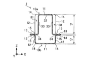
- the hat member (the upper member in FIG. 15) described in the first embodiment will be referred to as a “first hat member 10a”, and a hat member that is a counterpart member of the first hat member 10a ( The lower member in FIG. 15) is referred to as a "second hat member 10b".
- the second hat member 10b also has a top plate 11, a pair of vertical walls 12 connected to the top plate 11, and a flange 13 connected to the vertical wall 12.
- the automobile frame member 1 is configured by joining a first hat member 10a and a second hat member 10b with each other at a flange 13.
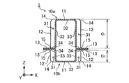
- the groove portion 31 of the first hat member 10a has a bottom surface 31a and a pair of side surfaces 31b when viewed from a direction perpendicular to the top plate 11 as shown in FIG.
- the groove portion 31 is provided so as to extend from the ridge line portion 14 to the ridge line portion 15 as shown in FIG. Therefore, the energy absorption efficiency can be improved.
- the second hat member 10b may be provided with the groove portion 31 similarly to the first hat member 10a.
- the energy absorption efficiency can be further improved.
- the groove 31 is provided in the second hat member 10b, and the width a of the groove 31, the height c 1 of the first hat member 10a and the sum c height c 2 of the second hat member 10b the ratio (a / c) of 0.2 to 0.3 and the depth b of the groove 31, the height c 2 of the first of the hat member 10a and the height c 1 second hat member 10b It is preferable that the ratio (b / c) to the sum c of 0.2 to 0.3.
- the angle ⁇ 1 between the bottom surface 31a of the groove 31 and the side surface 31b of the groove 31 is preferably 90 to 95 degrees, and more preferably vertical.
- the angle ⁇ 2 formed by the groove vertical wall 33 and the groove flange 34 is preferably 90 to 100 degrees, and more preferably vertical.
- both the first hat member and the second hat member 10b may have a groove forming portion 30, the height c 2 of the second hat member 10b between the height c 1 of the first hat member 10a
- the ratio (c 2 / c 1 ) is preferably 0.25 or less.
- c 2 / c 1 is more preferably 0.2 or less, further preferably 0.1 or less. That, c 2 / c 1 is preferably smaller.
- the vehicle frame member 1 of the first to third embodiments described above is configured by joining a plurality of members to each other
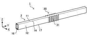
- the vehicle frame member 1 of the fourth embodiment is shown in FIGS.
- the hollow member 2 has a rectangular tubular shape.
- the hollow member 2 has a top plate 11, two vertical walls 12 connected to the top plate 11, and a bottom plate 16 connected to the two vertical walls 12.
- the two vertical walls 12 are respectively provided between the top plate 11 and the bottom plate 16, and the two vertical walls 12 face each other. Further, the top plate 11 and the bottom plate 16 also face each other.
- the material of the hollow member 2 is not particularly limited, and is, for example, a steel material, an aluminum alloy member, a magnesium alloy member, or the like.
- the bottom plate 16 of the hollow member 2 is a floor panel (not shown) as in the example of FIG. 3. Adjacent to the battery 42 mounted on.
- the automobile frame member 1 of the fourth embodiment has a plurality of groove portions 31 extending in a direction perpendicular to the member longitudinal direction of the hollow member 2, as in the first to third embodiments.
- the groove portion 31 is formed so as to extend from the ridge line portion 14 to the ridge line portion 17, that is, from the vehicle inner side end of the vertical wall 12 to the vehicle outer side end. Is preferred.
- the groove 31 is provided on both of the pair of vertical walls 12.
- the method for forming the groove 31 is not particularly limited. For example, after forming a rectangular tubular hollow member by extrusion molding, press processing is repeatedly performed to gradually increase the depth of the groove 31 to perform molding. Be seen. Further, the groove 31 may be formed by, for example, hydroforming.
- a plurality of groove forming portions 30 are provided along the member longitudinal direction of the hollow member 2. That is, the two vertical walls 12 are provided with a plurality of groove portions 31 along the member longitudinal direction of the hollow member 2.
- the top plate 11 in the groove forming portion 30 is referred to as a “groove portion top plate 32”
- the vertical wall 12 in the groove forming portion 30 is referred to as a “groove portion vertical wall 33”
- the bottom plate 16 in the groove forming portion 30 is referred to as “groove portion vertical wall 33”. It is called a groove bottom plate 35 ′′.
- the groove top plate 32 is located in the same plane as the top plate 11 other than the groove forming portion 30, and the groove bottom plate 35 is located in the same plane as the bottom plate 16 other than the groove forming portion 30.
- the shape of the groove portion 31 in plan view is the same as that of the first to third embodiments. That is, similarly to the case of FIG. 4, also in the vehicle frame member 1 of the fourth embodiment, the groove vertical wall 33 is a bottom surface 31 a of the groove 31 that is a surface parallel to the vertical wall 12 of the portion other than the groove forming portion 30. And a pair of flat side surfaces 31b connecting the vertical wall 12 other than the groove forming portion 30 and the bottom surface 31a of the groove portion 31. That is, the groove portion 31 includes a bottom surface 31a and two side surfaces 31b, and the two side surfaces 31b face each other and are located on both sides of the bottom surface 31a.
- the car frame member 1 of the fourth embodiment is configured as described above. Also in the automobile frame member 1 of the fourth embodiment, the width a of the groove 31 (FIG. 4), the depth b of the groove 31 (FIG. 4), and the height c of the vertical wall 12 of the hollow member 2 (FIG. 18). ) Satisfies the relationship of 0.2 ⁇ a / c ⁇ 0.3 and 0.2 ⁇ b / c ⁇ 0.3. Therefore, the energy absorption efficiency can be improved similarly to the automobile frame member 1 of the first to third embodiments.
- the height c of the vertical wall 12 of the hollow member 2 is the length from the bottom plate 16 to the top plate 11 in the direction perpendicular to the member longitudinal direction (Z direction).
- the height c of the vertical wall 12 of the hollow member 2 of the fourth embodiment is equal to the height from the groove bottom plate 35 to the groove top plate 32.
- the interval d (FIG. 4) between the adjacent groove portions 31 is preferably 50 mm or less as in the first to third embodiments.
- the interval d between the groove portions 31 is preferably 10 mm or more.
- the angle ⁇ 1 (FIG. 4) formed by the bottom surface 31a of the groove 31 and the side surface 31b of the groove 31 is 90 to 95 degrees, and Is more preferable.
- the angle ⁇ 3 formed by the groove vertical wall 33 and the groove bottom plate 35 be 80 to 90 degrees, as shown in FIG. Is more preferable.
- the groove portion 31 has the groove portion 31 as shown in FIG. In the example of FIG. 19, it may not be formed over the entire area from the ridge line portion 17) to the vehicle outer side end portion (ridge line portion 14 in the example of FIG. 19).
- the length e of the groove portion 31 in the direction perpendicular to the top plate 11 of the hollow member 2 is the height of the vertical wall 12 of the hollow member 2. The length is preferably 80% or more of the length c.
- the length e of the groove 31 is more preferably 90% or more of the height c of the vertical wall 12, and further preferably 95% or more. preferable.
- the length e of the groove 31 in the case where the automobile frame member 1 is composed of the hollow member 2 means the length R from the bottom plate 16 of the hollow member 2 to the R stop on the groove 31 side of the vertical wall 12 at the groove forming portion 30. Is the length of.
- the shape of the groove 31 with respect to the vertical wall 12 is concave, but it may be convex as shown in FIG. 20 or FIG.
- the width a of the groove portion 31, the depth b of the groove portion 31, and the height c of the vertical wall 12 are 0.2 ⁇ a / c ⁇ 0.3 and 0.2 ⁇ b. If the relationship of /c ⁇ 0.3 is satisfied, the axial crush mode is easily deformed, and the energy absorption efficiency can be improved.
- the length e of the groove portion 31 is 80% or more of the height c of the vertical wall 12, as in the above-described embodiment.
- the distance d between the groove portions 31 is 50 mm or less, as in the above-described embodiment.
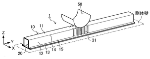
- FIG. 22 An analysis model (structure 1) as shown in FIG. 22 was created as an example of the automobile frame member according to the present disclosure, and a simulation simulating a pole side impact was performed.
- the analysis model of FIG. 22 has the same structure as the automobile frame member shown in FIG. 1, and is composed of the hat member 10 and the closing plate 20.
- the material of the hat member 10 and the closing plate 20 is a steel material having a tensile strength of 1180 MPa and a plate thickness of 1.6 mm.
- a plurality of groove forming portions 30 are provided in the central portion of the hat member 10 in the member longitudinal direction.
- the total length of the hat member 10 is 1500 mm
- the height c of the vertical wall 12 (length in the Z direction) and the width of the top plate 11 (length in the X direction) are 100 mm.
- the width a and the depth b of the groove 31 are each 20 mm. That is, the above-mentioned values of a / c and b / c are each 0.2.
- the groove interval is 20 mm.
- the simulation is performed by pressing the cylindrical impactor 50 having a radius of 127 mm against the closing plate 20 and displacing the impactor 50 at a speed of 1.8 km / h.
- a rigid wall is arranged on the top plate 11.
- an analysis model structure 2 having no groove portion in the hat member was created, and a simulation similar to the above conditions was performed.
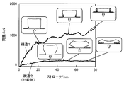
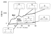
- FIG. 23 is a load-stroke diagram in the simulation (1).
- the arrow direction in FIG. 23 is the input direction.
- the structure 1 has a larger load than the structure 2 having no groove portion, and the energy absorption performance is improved.
- ⁇ Simulation (2)> As shown in FIG. 24, a rigid wall is arranged under the closing plate 20, and the simulation is performed by an analytical model in which the impactor 50 is applied to the top plate 11 of the hat member 10. The other simulation conditions are the same as in the simulation (1).
- FIG. 25 is a load-stroke diagram in the simulation (2).
- the arrow direction in FIG. 25 is the input direction.
- the structure 1 has a larger load than the structure 2 having no groove portion, and the energy absorption performance is improved. According to the results of the simulations (1) and (2), it is understood that the effect of improving the energy absorption performance can be obtained regardless of whether the top plate 11 is arranged outside the vehicle or inside the vehicle.
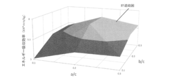
- Fig. 26 The relationship between a / c, b / c, and energy absorption efficiency in simulation (3) is summarized in Fig. 26.
- the “suitable range” shown in FIG. 26 is a range in which the energy absorption efficiency (absorbed energy / mass) is 5.0 [kN * mm / kg] or more.
- the energy absorption efficiency was particularly high.
- FIG. 27 in this simulation, when a / c is 0.2 to 0.3 and b / c is 0.2 to 0.3, the car frame member is Deformation of the axial crush mode occurred.
- FIG. 28 is a diagram showing a relationship between e / c and energy absorption efficiency in the simulation (4).
- e / c when e / c is 0.8 or more, the energy absorption efficiency is dramatically improved as compared with the case where e / c is less than 0.8.
- e / c when e / c was 0.8 and 1.0, the vehicle frame member was deformed in the axial crush mode. That is, when the length e of the groove is 80% or more of the height c of the vertical wall, the axial crush mode is easily deformed, and the energy absorption efficiency can be effectively improved.
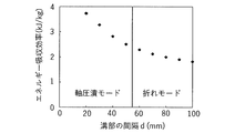
- FIG. 29 is a diagram showing a relationship between the groove interval d in the simulation (5) and the energy absorption efficiency. As shown in FIG. 29, under the conditions of this simulation, when the groove interval d is 50 mm or less, the deformation in the axial crush mode occurs, and the energy absorption efficiency is improved.
- ⁇ Simulation (6)> a simulation was carried out by creating an analysis model in which the automobile frame member was composed of the first hat member and the second hat member.
- the materials of the first hat member and the second hat member are steel materials having a tensile strength of 1180 MPa. Grooves are provided in the first hat member and the second hat member, respectively, as shown in FIG.
- the ratio between the height c 2 of the second hat member and the height c 1 of the first hat member (c 2 / c 1) is 0.25.
- the shape of the groove is the same for the first hat member and the second hat member except for the height difference of the hat member.
- the other simulation conditions are the same as in the simulation (1).
- the simulation is performed in a plurality of analytical models in which the width a of the groove and the depth b of the groove are different.
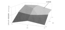
- FIG. “C” is the sum of the height c 1 of the first hat member and the height c 2 of the second hat member.
- the “suitable range” shown in FIG. 30 is a range in which the energy absorption efficiency is 5.0 [kN * mm / kg] or more. Similar to the simulation (3), when a / c is 0.2 to 0.3 and b / c is 0.2 to 0.3, the deformation in the axial crushing mode is caused in the automobile frame member. And the mass efficiency of energy absorption performance was improved.
- the deformation mode of the automobile frame member when a / c was less than 0.2 and b / c was 0.2 to 0.3 was the in-plane deformation mode.
- the energy absorption efficiency was 5.0 [kN * mm / kg] or more. The reason for such a result is that when the automobile frame member is deformed, the vertical wall between the groove portions comes into contact with the adjacent vertical wall to increase the load.
- the technology according to the present disclosure can be used for side sills and bumper beams of automobiles.
- Automotive frame member 2 Hollow member 10 Hat member 10a First hat member 10b Second hat member 11 Top plate 12 Vertical wall 13 Flange 14 Ridge line portion 15 Ridge line portion 16 Bottom plate 17 Ridge line portion 20 Closing plate 30 Groove forming portion 31 Groove portion 31a Groove bottom 31b Groove side 32 Groove top 33 Groove vertical wall 34 Groove flange 35 Groove bottom plate 40 Electric vehicle 41 Side sill 42 Battery 50 Impactor a Groove width b Groove depth c Groove height d Groove spacing e Length of groove ⁇ 1 Angle between bottom of groove and side of groove ⁇ 2 Angle between vertical wall of groove and flange of groove ⁇ 3 Angle between vertical wall of groove and bottom plate of groove
Landscapes
- Engineering & Computer Science (AREA)
- Mechanical Engineering (AREA)
- Chemical & Material Sciences (AREA)
- Combustion & Propulsion (AREA)
- Transportation (AREA)
- Body Structure For Vehicles (AREA)
- Arrangement Or Mounting Of Propulsion Units For Vehicles (AREA)
Abstract
Description
図1は、第1の実施形態における自動車骨格部材1の概略構成を示す図である。自動車骨格部材1は、サイドシルまたはバンパービーム等の曲げ荷重を受ける部材である。第1の実施形態の自動車骨格部材1は、部材長手方向(図1のY方向)に垂直な断面がハット形状の部材であるハット部材10と、ハット部材10に接合される底板である平板状のクロージングプレート20とを有している。なお、図1に示すX方向、Y方向およびZ方向は互いに垂直な方向であり、自動車骨格部材1が例えばサイドシルを構成する部材である場合は、X方向が車高方向、Y方向が車長方向、Z方向が車幅方向である。また、自動車骨格部材1が例えばバンパービームを構成する部材である場合は、X方向が車高方向、Y方向が車幅方向、Z方向が車長方向である。
図7および図8に示されるように、面外折れモードは、主な変形が、部材長手方向に垂直な断面においてハット部材10の縦壁12が面外方向に折れる変形となるモードである。
(面内折れモード)
図9に示されるように、面内折れモードは、主な変形が、部材長手方向に沿ってハット部材10の縦壁12が折れる変形であり、部材長手方向に垂直な断面における面外方向への縦壁12の変形が小さいモードである。
(軸圧潰モード)
図10および図11に示されるように、軸圧潰モードは、部材長手方向に垂直な断面においてハット部材10の縦壁12が短い間隔で圧潰し、全体として蛇腹状の変形が生じるモードである。
図12および図13に示されるように第2の実施形態の自動車骨格部材1は、溝部31がハット部材10の稜線部14まで延びていない。すなわち、第2の実施形態の自動車骨格部材1においては、溝部31の一方端が縦壁12の車内側端部(図14の例では稜線部15)まで延びているものの、溝部31の他方端は縦壁12の車外側端部(図14の例では稜線部14)までは延びていない。このような形状の溝部31であっても、溝部31の幅aと、溝部31の深さbと、ハット部材10の縦壁12の高さcが、0.2≦a/c≦0.3、かつ、0.2≦b/c≦0.3の関係を満たすことで、軸圧潰モードの変形が生じやすくなり、エネルギー吸収効率を向上させることができる。
第1の実施形態における自動車骨格部材1は、ハット部材10の相手部材がクロージングプレート20であった。図15に示される第2の実施形態の自動車骨格部材1は、相手部材もハット部材となっている。以降の説明では、第1の実施形態で説明したハット部材(図15中の上側の部材)を“第1のハット部材10a”と称し、第1のハット部材10aの相手部材となるハット部材(図15中の下側の部材)を“第2のハット部材10b”と称す。第2のハット部材10bも第1のハット部材10aと同様に、天板11と、天板11に繋がる一対の縦壁12と、縦壁12に繋がるフランジ13とを有している。自動車骨格部材1は、第1のハット部材10aと第2のハット部材10bが互いのフランジ13で接合されることで構成されている。第2の実施形態の自動車骨格部材1においても、第1のハット部材10aの溝部31は、図4のように天板11に垂直な方向から見たときに底面31aと一対の側面31bとを有しており、当該溝部31は、図15に示されるように稜線部14から稜線部15にわたって設けられている。このため、エネルギー吸収効率を向上させることができる。
前述の第1~第3の実施形態の自動車骨格部材1は、複数の部材が互いに接合されることで構成されていたが、第4の実施形態の自動車骨格部材1は、図17および図18に示されるように角管状の中空部材2で構成されている。中空部材2は、天板11と、天板11に繋がる2つの縦壁12と、2つの縦壁12に繋がる底板16とを有している。2つの縦壁12は、それぞれ天板11と、底板16の間にあり、2つ縦壁12は、向かい合っている。また、天板11と底板16も向かい合っている。中空部材2の素材は特に限定されず、例えば鋼材、アルミニウム合金部材やマグネシウム合金部材等である。第4の実施形態の自動車骨格部材1が、例えば電気自動車40のサイドシル41を構成する部材である場合、図3の例と同様に、中空部材2の底板16が、フロアパネル(図示せず)に載せられた電池42に隣接する。
本開示に係る自動車骨格部材の一例として図22のような解析モデル(構造1)を作成し、ポール側突を模擬したシミュレーションを実施した。図22の解析モデルは、図1に示される自動車骨格部材と同等の構成を有しており、ハット部材10とクロージングプレート20で構成されている。ハット部材10およびクロージングプレート20の素材は、引張強度が1180MPa、板厚が1.6mmの鋼材である。ハット部材10の部材長手方向の中央部には複数の溝形成箇所30が設けられている。ハット部材10の全長は1500mm、縦壁12の高さc(Z方向の長さ)および天板11の幅(X方向の長さ)は、それぞれ100mmである。溝部31の幅aおよび深さbはそれぞれ20mmである。すなわち、前述のa/cおよびb/cの値は、それぞれ0.2である。溝部の間隔は20mmである。
図24のように剛体壁をクロージングプレート20の下に配置し、ハット部材10の天板11にインパクタ50を当てる解析モデルでシミュレーションを実施した。なお、その他のシミュレーション条件は、シミュレーション(1)と同様である。
次に、溝部の幅a(図4)と縦壁の高さc(図6)の比、および溝部の深さb(図4)と縦壁の高さc(図6)の比が異なる解析モデルを複数作成し、各解析モデルでシミュレーションを実施した。なお、その他のシミュレーション条件は、シミュレーション(1)と同様である。
次に、図13のような溝部31が縦壁12の天板11側の稜線部14まで延びていない構造において、溝部の長さeと、縦壁の高さcの比が異なる解析モデルを複数作成し、各解析モデルでシミュレーションを実施した。なお、その他のシミュレーション条件は、シミュレーション(2)と同様である。
次に、溝部の間隔d(図4)が異なる解析モデルを複数作成し、各解析モデルでシミュレーションを実施した。なお、その他のシミュレーション条件は、シミュレーション(2)と同様である。
次に、自動車骨格部材が第1のハット部材と第2のハット部材で構成された解析モデルを作成してシミュレーションを実施した。第1のハット部材および第2のハット部材の素材は、引張強度が1180MPaの鋼材である。第1のハット部材および第2のハット部材には、図16のようにそれぞれ溝部が設けられている。本シミュレーションでは、第2のハット部材の高さc2と第1のハット部材の高さc1との比(c2/c1)は、0.25である。溝部の形状は、ハット部材の高さの違いを除き、第1のハット部材と第2のハット部材で同様である。その他のシミュレーション条件は、シミュレーション(1)と同様である。シミュレーションは、溝部の幅aと、溝部の深さbが異なる複数の解析モデルにおいて実施されている。
2 中空部材
10 ハット部材
10a 第1のハット部材
10b 第2のハット部材
11 天板
12 縦壁
13 フランジ
14 稜線部
15 稜線部
16 底板
17 稜線部
20 クロージングプレート
30 溝形成箇所
31 溝部
31a 溝部の底面
31b 溝部の側面
32 溝部天板
33 溝部縦壁
34 溝部フランジ
35 溝部底板
40 電気自動車
41 サイドシル
42 電池
50 インパクタ
a 溝部の幅
b 溝部の深さ
c 縦壁の高さ
d 溝部の間隔
e 溝部の長さ
θ1 溝部の底面と溝部の側面とのなす角
θ2 溝部縦壁と溝部フランジとのなす角
θ3 溝部縦壁と溝部底板とのなす角
Claims (8)
- ハット部材と、クロージングプレートを備え、
前記ハット部材は、天板と、2つの縦壁と、2つのフランジを備え、
前記2つの縦壁は、それぞれ前記天板と前記フランジの間にあり、
前記2つの縦壁は、向かい合い、
前記2つのフランジは、それぞれ前記クロージングプレートと接合され、
前記2つの縦壁はそれぞれ、前記ハット部材の長手方向に垂直な方向に延びる複数の溝部を備え、
前記溝部は、底面と、2つの側面を備え、
前記2つの側面は、向かい合い、
前記2つの側面は、前記底面の両側にあり、
前記天板に平行な断面における前記溝部の幅aと前記溝部の深さbと、前記天板に垂直な方向における前記縦壁の高さcは、0.2≦a/c≦0.3、かつ、0.2≦b/c≦0.3の関係を満たす、自動車骨格部材。 - 前記溝部は、前記縦壁の車内側端部まで延び、
前記天板に垂直な方向における前記溝部の長さeは、前記縦壁の高さcの80%以上の長さである、請求項1に記載の自動車骨格部材。 - 前記溝部の間隔dは、50mm以下である、請求項1又は2に記載の自動車骨格部材。
- 中空部材を備え、
前記中空部材は、天板と、底板と、2つの縦壁を備え、
前記天板と前記底板は、向かい合い、
前記2つの縦壁は、それぞれ前記天板と前記底板の間にあり、
前記2つの縦壁は、向かい合い、
前記2つの縦壁はそれぞれ、前記中空部材の長手方向に垂直な方向に延びる複数の溝部を備え、
前記溝部は、底面と、2つの側面を備え、
前記2つの側面は、向かい合い、
前記2つの側面は、前記底面の両側にあり、
前記天板に平行な断面における前記溝部の幅aと前記溝部の深さbと、前記天板に垂直な方向における前記縦壁の高さcは、0.2≦a/c≦0.3、かつ、0.2≦b/c≦0.3の関係を満たす、自動車骨格部材。 - 前記溝部は、前記縦壁の車内側端部まで延び、
前記天板に垂直な方向における前記溝部の長さeは、前記縦壁の高さcの80%以上の長さである、請求項4に記載の自動車骨格部材。 - 前記溝部の間隔dは、50mm以下である、請求項4又は5に記載の自動車骨格部材。
- 請求項1~3のいずれか一項に記載の自動車骨格部材を備えたサイドシルと、電池とを備え、
車高方向に垂直な断面において、前記クロージングプレートは、前記電池に隣接し、前記天板は、車外側に配置されている、電気自動車。 - 請求項4~6のいずれか一項に記載の自動車骨格部材を備えたサイドシルと、電池とを備え、
車高方向に垂直な断面において前記底板は、前記電池に隣接し、
前記天板は、車外側に配置されている、電気自動車。
Priority Applications (4)
| Application Number | Priority Date | Filing Date | Title |
|---|---|---|---|
| US17/284,995 US11208150B2 (en) | 2018-10-24 | 2019-10-23 | Automotive frame member and electric vehicle |
| CN201980068245.9A CN112867637B (zh) | 2018-10-24 | 2019-10-23 | 汽车骨架构件和电动汽车 |
| JP2020506390A JP6703322B1 (ja) | 2018-10-24 | 2019-10-23 | 自動車骨格部材および電気自動車 |
| EP19876878.0A EP3851335A4 (en) | 2018-10-24 | 2019-10-23 | MOTOR VEHICLE FRAME ELEMENT AND ELECTRIC VEHICLE |
Applications Claiming Priority (2)
| Application Number | Priority Date | Filing Date | Title |
|---|---|---|---|
| JP2018199818 | 2018-10-24 | ||
| JP2018-199818 | 2018-10-24 |
Publications (1)
| Publication Number | Publication Date |
|---|---|
| WO2020085381A1 true WO2020085381A1 (ja) | 2020-04-30 |
Family
ID=70331125
Family Applications (1)
| Application Number | Title | Priority Date | Filing Date |
|---|---|---|---|
| PCT/JP2019/041527 Ceased WO2020085381A1 (ja) | 2018-10-24 | 2019-10-23 | 自動車骨格部材および電気自動車 |
Country Status (5)
| Country | Link |
|---|---|
| US (1) | US11208150B2 (ja) |
| EP (1) | EP3851335A4 (ja) |
| JP (1) | JP6703322B1 (ja) |
| CN (1) | CN112867637B (ja) |
| WO (1) | WO2020085381A1 (ja) |
Cited By (1)
| Publication number | Priority date | Publication date | Assignee | Title |
|---|---|---|---|---|
| CN116157318A (zh) * | 2020-07-31 | 2023-05-23 | 日本制铁株式会社 | 汽车车身的结构构件 |
Families Citing this family (6)
| Publication number | Priority date | Publication date | Assignee | Title |
|---|---|---|---|---|
| CN116056956B (zh) * | 2020-07-31 | 2026-02-24 | 日本制铁株式会社 | 汽车车身构造部件 |
| KR20240093636A (ko) | 2021-11-18 | 2024-06-24 | 제이에프이 스틸 가부시키가이샤 | 자동차의 차체 하부 구조 및 사이드 실 구조 |
| WO2023133563A1 (en) | 2022-01-07 | 2023-07-13 | Shape Corp. | Rocker insert with corrugated structure |
| JP7394173B1 (ja) | 2022-06-03 | 2023-12-07 | Jfeスチール株式会社 | 車体側部構造 |
| WO2024019754A1 (en) * | 2022-07-19 | 2024-01-25 | Shape Corp. | Rocker insert with a plurality of beads |
| WO2024091269A1 (en) * | 2022-10-28 | 2024-05-02 | Atieva, Inc. | Stamped energy absorption side structure for vehicle |
Citations (5)
| Publication number | Priority date | Publication date | Assignee | Title |
|---|---|---|---|---|
| JP2006207679A (ja) | 2005-01-27 | 2006-08-10 | Honda Motor Co Ltd | 衝撃吸収部材の製造方法 |
| JP2006205797A (ja) | 2005-01-26 | 2006-08-10 | Mitsubishi Motors Corp | 車体補強構造 |
| DE102006001061A1 (de) * | 2006-01-07 | 2007-09-06 | GM Global Technology Operations, Inc., Detroit | Kraftfahrzeug mit wenigstens einem längsseitig an seiner Karosserie verlaufenden, verstärkten Türschweller |
| JP2008265738A (ja) | 2007-03-28 | 2008-11-06 | Unipres Corp | 車両用金属製アブソーバ、車両用バンパシステム、自動車バンパ用アブソーバ及び自動車バンパシステム |
| JP2018131133A (ja) * | 2017-02-17 | 2018-08-23 | 本田技研工業株式会社 | 車体の下部構造 |
Family Cites Families (10)
| Publication number | Priority date | Publication date | Assignee | Title |
|---|---|---|---|---|
| DE10309636B4 (de) * | 2003-03-04 | 2012-08-09 | Audi Ag | Karosserieträger mit einer den Verformungsverlauf bei einem Aufprall beeinflussenden Nebenform |
| JP2009227037A (ja) * | 2008-03-21 | 2009-10-08 | Toyota Motor Corp | 車両のバンパ構造及びエネルギ吸収体 |
| BR112014029809A2 (pt) * | 2012-06-04 | 2017-06-27 | Nippon Steel & Sumitomo Metal Corp | estrutura de elemento de carroceria de veículo com excelente desempenho de resistência a impacto |
| DE102014016044A1 (de) * | 2014-10-29 | 2016-05-04 | GM Global Technology Operations LLC (n. d. Ges. d. Staates Delaware) | Frontpartie eines Kraftfahrzeugs und Stoßfängeraussteifung dazu |
| JP6308190B2 (ja) * | 2015-09-14 | 2018-04-11 | トヨタ自動車株式会社 | 車体骨格構造 |
| JP6889419B2 (ja) * | 2017-03-10 | 2021-06-18 | マツダ株式会社 | 車両の下部車体構造 |
| US11097789B2 (en) * | 2017-04-10 | 2021-08-24 | Nippon Steel Corporation | Structural member for automobiles and method for producing the same |
| US10886513B2 (en) * | 2017-05-16 | 2021-01-05 | Shape Corp. | Vehicle battery tray having tub-based integration |
| US10293862B1 (en) * | 2018-01-12 | 2019-05-21 | Ford Global Technologies, Llc | Side sill assembly reinforced with a tube and box-shaped brackets |
| US10850774B2 (en) * | 2018-11-13 | 2020-12-01 | Dura Operating, Llc | Side rail assembly for a vehicle |
-
2019
- 2019-10-23 CN CN201980068245.9A patent/CN112867637B/zh active Active
- 2019-10-23 US US17/284,995 patent/US11208150B2/en active Active
- 2019-10-23 EP EP19876878.0A patent/EP3851335A4/en active Pending
- 2019-10-23 WO PCT/JP2019/041527 patent/WO2020085381A1/ja not_active Ceased
- 2019-10-23 JP JP2020506390A patent/JP6703322B1/ja active Active
Patent Citations (5)
| Publication number | Priority date | Publication date | Assignee | Title |
|---|---|---|---|---|
| JP2006205797A (ja) | 2005-01-26 | 2006-08-10 | Mitsubishi Motors Corp | 車体補強構造 |
| JP2006207679A (ja) | 2005-01-27 | 2006-08-10 | Honda Motor Co Ltd | 衝撃吸収部材の製造方法 |
| DE102006001061A1 (de) * | 2006-01-07 | 2007-09-06 | GM Global Technology Operations, Inc., Detroit | Kraftfahrzeug mit wenigstens einem längsseitig an seiner Karosserie verlaufenden, verstärkten Türschweller |
| JP2008265738A (ja) | 2007-03-28 | 2008-11-06 | Unipres Corp | 車両用金属製アブソーバ、車両用バンパシステム、自動車バンパ用アブソーバ及び自動車バンパシステム |
| JP2018131133A (ja) * | 2017-02-17 | 2018-08-23 | 本田技研工業株式会社 | 車体の下部構造 |
Non-Patent Citations (1)
| Title |
|---|
| See also references of EP3851335A4 |
Cited By (1)
| Publication number | Priority date | Publication date | Assignee | Title |
|---|---|---|---|---|
| CN116157318A (zh) * | 2020-07-31 | 2023-05-23 | 日本制铁株式会社 | 汽车车身的结构构件 |
Also Published As
| Publication number | Publication date |
|---|---|
| CN112867637B (zh) | 2025-06-27 |
| JP6703322B1 (ja) | 2020-06-03 |
| US20210245812A1 (en) | 2021-08-12 |
| EP3851335A1 (en) | 2021-07-21 |
| JPWO2020085381A1 (ja) | 2021-02-15 |
| EP3851335A4 (en) | 2021-10-27 |
| US11208150B2 (en) | 2021-12-28 |
| CN112867637A (zh) | 2021-05-28 |
Similar Documents
| Publication | Publication Date | Title |
|---|---|---|
| JP6703322B1 (ja) | 自動車骨格部材および電気自動車 | |
| JP6973517B2 (ja) | 車両用構造部材 | |
| US20250010918A1 (en) | Lower structure of automotive body and side sill structure of automobile | |
| CN105923048A (zh) | 车辆用车架 | |
| US11414032B2 (en) | Closed cross-sectional structure member having high collision performance and automobile body structure | |
| CN108495777A (zh) | 车辆前部构造 | |
| US20240097256A1 (en) | Battery case of automobile and method for manufacturing the same | |
| WO2019035185A1 (ja) | バンパービーム及び車両 | |
| KR20120138785A (ko) | 자동차용 부품 | |
| US11981370B2 (en) | Structural member for vehicle | |
| US12583521B2 (en) | Automobile underbody structure | |
| JP7568928B2 (ja) | 衝撃吸収部材 | |
| CN118251341A (zh) | 汽车的车体下部结构及侧梁结构 | |
| JP7376797B2 (ja) | 自動車骨格部材および電気自動車 | |
| WO2025079670A1 (ja) | 自動車骨格部材の接合構造 | |
| JP6565291B2 (ja) | 衝撃吸収部材、車体および衝撃吸収方法 | |
| CN209795397U (zh) | 一种前防撞梁总成结构及其车辆 | |
| JP7264597B2 (ja) | 車両用構造部材及び車両 | |
| WO2020085383A1 (ja) | 自動車骨格部材および電気自動車 | |
| JP6687179B1 (ja) | 自動車骨格部材および電気自動車 | |
| CN112689594A (zh) | 面板构件 | |
| JP7252443B2 (ja) | 車体部材、および、車体構造 | |
| EP3604086B1 (en) | Shock-absorbing member and side member of automobile | |
| WO2018088099A1 (ja) | 車両の衝撃吸収構造 |
Legal Events
| Date | Code | Title | Description |
|---|---|---|---|
| ENP | Entry into the national phase |
Ref document number: 2020506390 Country of ref document: JP Kind code of ref document: A |
|
| 121 | Ep: the epo has been informed by wipo that ep was designated in this application |
Ref document number: 19876878 Country of ref document: EP Kind code of ref document: A1 |
|
| NENP | Non-entry into the national phase |
Ref country code: DE |
|
| ENP | Entry into the national phase |
Ref document number: 2019876878 Country of ref document: EP Effective date: 20210415 |
|
| WWG | Wipo information: grant in national office |
Ref document number: 201980068245.9 Country of ref document: CN |