WO2020090388A1 - 地図生成システム、地図生成方法及び地図生成プログラム - Google Patents
地図生成システム、地図生成方法及び地図生成プログラム Download PDFInfo
- Publication number
- WO2020090388A1 WO2020090388A1 PCT/JP2019/039806 JP2019039806W WO2020090388A1 WO 2020090388 A1 WO2020090388 A1 WO 2020090388A1 JP 2019039806 W JP2019039806 W JP 2019039806W WO 2020090388 A1 WO2020090388 A1 WO 2020090388A1
- Authority
- WO
- WIPO (PCT)
- Prior art keywords
- information
- unit
- point data
- map generation
- linearization
- Prior art date
- Legal status (The legal status is an assumption and is not a legal conclusion. Google has not performed a legal analysis and makes no representation as to the accuracy of the status listed.)
- Ceased
Links
Images


Classifications
-
- G—PHYSICS
- G06—COMPUTING OR CALCULATING; COUNTING
- G06T—IMAGE DATA PROCESSING OR GENERATION, IN GENERAL
- G06T11/00—Two-dimensional [2D] image generation
- G06T11/20—Drawing from basic elements
- G06T11/23—Drawing from basic elements using straight lines or curves
-
- G—PHYSICS
- G01—MEASURING; TESTING
- G01C—MEASURING DISTANCES, LEVELS OR BEARINGS; SURVEYING; NAVIGATION; GYROSCOPIC INSTRUMENTS; PHOTOGRAMMETRY OR VIDEOGRAMMETRY
- G01C21/00—Navigation; Navigational instruments not provided for in groups G01C1/00 - G01C19/00
- G01C21/38—Electronic maps specially adapted for navigation; Updating thereof
- G01C21/3804—Creation or updating of map data
- G01C21/3807—Creation or updating of map data characterised by the type of data
- G01C21/3815—Road data
- G01C21/3819—Road shape data, e.g. outline of a route
-
- G—PHYSICS
- G06—COMPUTING OR CALCULATING; COUNTING
- G06T—IMAGE DATA PROCESSING OR GENERATION, IN GENERAL
- G06T11/00—Two-dimensional [2D] image generation
- G06T11/60—Creating or editing images; Combining images with text
-
- G—PHYSICS
- G06—COMPUTING OR CALCULATING; COUNTING
- G06T—IMAGE DATA PROCESSING OR GENERATION, IN GENERAL
- G06T7/00—Image analysis
- G06T7/10—Segmentation; Edge detection
- G06T7/12—Edge-based segmentation
-
- G—PHYSICS
- G06—COMPUTING OR CALCULATING; COUNTING
- G06T—IMAGE DATA PROCESSING OR GENERATION, IN GENERAL
- G06T7/00—Image analysis
- G06T7/10—Segmentation; Edge detection
- G06T7/13—Edge detection
-
- G—PHYSICS
- G06—COMPUTING OR CALCULATING; COUNTING
- G06T—IMAGE DATA PROCESSING OR GENERATION, IN GENERAL
- G06T7/00—Image analysis
- G06T7/10—Segmentation; Edge detection
- G06T7/136—Segmentation; Edge detection involving thresholding
-
- G—PHYSICS
- G06—COMPUTING OR CALCULATING; COUNTING
- G06T—IMAGE DATA PROCESSING OR GENERATION, IN GENERAL
- G06T7/00—Image analysis
- G06T7/10—Segmentation; Edge detection
- G06T7/162—Segmentation; Edge detection involving graph-based methods
-
- G—PHYSICS
- G06—COMPUTING OR CALCULATING; COUNTING
- G06T—IMAGE DATA PROCESSING OR GENERATION, IN GENERAL
- G06T7/00—Image analysis
- G06T7/10—Segmentation; Edge detection
- G06T7/181—Segmentation; Edge detection involving edge growing; involving edge linking
-
- G—PHYSICS
- G06—COMPUTING OR CALCULATING; COUNTING
- G06V—IMAGE OR VIDEO RECOGNITION OR UNDERSTANDING
- G06V20/00—Scenes; Scene-specific elements
- G06V20/50—Context or environment of the image
- G06V20/56—Context or environment of the image exterior to a vehicle by using sensors mounted on the vehicle
- G06V20/588—Recognition of the road, e.g. of lane markings; Recognition of the vehicle driving pattern in relation to the road
-
- G—PHYSICS
- G08—SIGNALLING
- G08G—TRAFFIC CONTROL SYSTEMS
- G08G1/00—Traffic control systems for road vehicles
- G08G1/09—Arrangements for giving variable traffic instructions
- G08G1/0962—Arrangements for giving variable traffic instructions having an indicator mounted inside the vehicle, e.g. giving voice messages
- G08G1/0968—Systems involving transmission of navigation instructions to the vehicle
- G08G1/0969—Systems involving transmission of navigation instructions to the vehicle having a display in the form of a map
-
- G—PHYSICS
- G09—EDUCATION; CRYPTOGRAPHY; DISPLAY; ADVERTISING; SEALS
- G09B—EDUCATIONAL OR DEMONSTRATION APPLIANCES; APPLIANCES FOR TEACHING, OR COMMUNICATING WITH, THE BLIND, DEAF OR MUTE; MODELS; PLANETARIA; GLOBES; MAPS; DIAGRAMS
- G09B9/00—Simulators for teaching or training purposes
- G09B9/003—Simulators for teaching or training purposes for military purposes and tactics
-
- G—PHYSICS
- G06—COMPUTING OR CALCULATING; COUNTING
- G06T—IMAGE DATA PROCESSING OR GENERATION, IN GENERAL
- G06T11/00—Two-dimensional [2D] image generation
- G06T11/60—Creating or editing images; Combining images with text
- G06T11/65—Creating or editing images; Combining images with text on geographic maps
-
- G—PHYSICS
- G06—COMPUTING OR CALCULATING; COUNTING
- G06T—IMAGE DATA PROCESSING OR GENERATION, IN GENERAL
- G06T2200/00—Indexing scheme for image data processing or generation, in general
- G06T2200/24—Indexing scheme for image data processing or generation, in general involving graphical user interfaces [GUIs]
-
- G—PHYSICS
- G06—COMPUTING OR CALCULATING; COUNTING
- G06T—IMAGE DATA PROCESSING OR GENERATION, IN GENERAL
- G06T2207/00—Indexing scheme for image analysis or image enhancement
- G06T2207/10—Image acquisition modality
- G06T2207/10028—Range image; Depth image; 3D point clouds
-
- G—PHYSICS
- G06—COMPUTING OR CALCULATING; COUNTING
- G06T—IMAGE DATA PROCESSING OR GENERATION, IN GENERAL
- G06T2207/00—Indexing scheme for image analysis or image enhancement
- G06T2207/20—Special algorithmic details
- G06T2207/20092—Interactive image processing based on input by user
- G06T2207/20101—Interactive definition of point of interest, landmark or seed
-
- G—PHYSICS
- G06—COMPUTING OR CALCULATING; COUNTING
- G06T—IMAGE DATA PROCESSING OR GENERATION, IN GENERAL
- G06T2207/00—Indexing scheme for image analysis or image enhancement
- G06T2207/30—Subject of image; Context of image processing
- G06T2207/30248—Vehicle exterior or interior
- G06T2207/30252—Vehicle exterior; Vicinity of vehicle
- G06T2207/30256—Lane; Road marking
-
- G—PHYSICS
- G06—COMPUTING OR CALCULATING; COUNTING
- G06T—IMAGE DATA PROCESSING OR GENERATION, IN GENERAL
- G06T2210/00—Indexing scheme for image generation or computer graphics
- G06T2210/56—Particle system, point based geometry or rendering
Definitions
- the present invention relates to a technique for generating information such as a lane marking and a road shoulder edge based on measurement information around a road obtained by a measuring device.
- a highly accurate method of generating map information is to run a measurement vehicle called MMS (Mobile Mapping System) to acquire 3D point cloud information of features such as road surface and equipment beside the road, and to obtain 3D point information. It is considered to generate map information based on group information.
- MMS Mobile Mapping System
- the plotting process for generating the map information based on the three-dimensional point cloud information is necessary as the map information such as the division line on the road and the line representing the road shoulder edge from the three-dimensional point cloud information. This is a process of generating a line indicating the position of the boundary. The information representing this line is called linearized information.
- Patent Document 1 discloses that an orthoimage of a road image viewed from directly above is generated and a road sign is recognized from a two-dimensional image.
- Patent Document 2 discloses that linearization information of a feature is generated from a plurality of still images of a road and the deviation of the linearization information is detected by comparing different images.
- An object of the present invention is to enable manual error correction of linearized information efficiently.
- the map generation system Based on the measurement information around the roadway obtained by the measuring device, a plotting unit that generates linearization information that represents at least one of a lane marking and a road shoulder edge of the roadway, An evaluation unit that calculates an evaluation value indicating the reliability of the partial information, for each partial information that constitutes the linearized information generated by the plotting unit, A display unit that displays the linearized information by displaying the partial information in a different display mode according to the evaluation value calculated by the evaluation unit.
- the partial information of the linearization information is displayed in different display modes according to the evaluation value. This makes it possible to easily identify a portion of the linearization information that is likely to be erroneous. Therefore, it is possible to efficiently perform error correction on the linearized information manually.
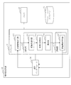
- FIG. 1 is a configuration diagram of a map generation system 1 according to the first embodiment.
- 1 is a configuration diagram of a map generation device 10 according to the first embodiment.
- 3 is a configuration diagram of an evaluation unit 113 according to the first embodiment.
- FIG. 1 is a configuration diagram of a map editing device 20 according to the first embodiment.
- 3 is a flowchart of the overall processing of the map generation system 1 according to the first embodiment.
- 3 is a flowchart of a plotting process according to the first embodiment.
- FIG. 6 is an explanatory diagram of a process of identifying point data representing a lane marking according to the first embodiment.
- FIG. 6 is an explanatory diagram of a process of identifying point data representing a lane marking according to the first embodiment.
- FIG. 6 is an explanatory diagram of a process of identifying point data representing a road shoulder edge according to the first embodiment.
- FIG. 6 is an explanatory diagram of a process of identifying point data representing a road shoulder edge according to the first embodiment.
- FIG. 6 is an explanatory diagram of a grouping process according to the first embodiment.
- FIG. 6 is an explanatory diagram of a process of excluding candidate point data according to the first embodiment.
- 7 is an explanatory diagram of a process of connecting between groups according to the first embodiment.
- FIG. 7 is an explanatory diagram of a process of connecting between groups according to the first embodiment.
- FIG. FIG. 4 is an explanatory diagram of correction 1 according to the first embodiment.
- FIG. 3 is an explanatory diagram of correction 2 according to the first embodiment.
- FIG. 5 is an explanatory diagram of correction 3 according to the first embodiment.
- 9 is a flowchart of an evaluation process when the linearization information according to the first embodiment represents a lane marking.
- FIG. 6 is an explanatory diagram of a process of the parallelism evaluation unit 82 according to the first embodiment.
- 9 is a flowchart of an evaluation process when the linearized information according to the first embodiment represents a road shoulder edge.
- 3 is a flowchart of display processing according to the first embodiment.
- FIG. 6 is an explanatory diagram of a linearized information display process according to the first embodiment.
- 3 is a flowchart of editing processing according to the first embodiment.
- 7A and 7B are explanatory diagrams of processing of the display unit 211 according to the first embodiment.
- FIG. 6 is an explanatory diagram of a process of moving the position of a node according to the first embodiment.
- FIG. 6 is an explanatory diagram of a process of adding a new link according to the first embodiment.
- FIG. 6 is an explanatory diagram of a process of adding a new link according to the first embodiment.
- the block diagram of the map generation apparatus 10 which concerns on the modification 2.
- the block diagram of the map editing device 20 which concerns on the modification 2.
- FIG. 3 is a configuration diagram of a map editing device 20 according to a second embodiment.
- FIG. 11 is a diagram showing a transition example of a screen when continuously displaying partial information belonging to the same group according to the second embodiment.
- FIG. 11 is a diagram showing a transition example of a screen when continuously displaying partial information belonging to the same group according to the second embodiment.
- 6 is a configuration diagram of a map generation device 10 according to a third embodiment.
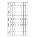
- FIG. The figure which shows the example of the data which the evaluation function learning part 117 which concerns on Embodiment 3 uses for learning.
- the figure which shows the example of the comprehensive evaluation value after learning which concerns on Embodiment 3.
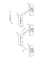
- the map generation system 1 includes a map generation device 10, a map editing device 20, a measurement information storage device 30, a primary map storage device 40, and a secondary map storage device 50.
- the map generation device 10 is connected to the measurement information storage device 30 and the primary map storage device 40 via a transmission line 60.
- the map editing device 20 is connected to the primary map storage device 40 and the secondary map storage device 50 via a transmission path 70.
- the map generation device 10 and the map editing device 20 are configured as separate devices. However, the map generation device 10 and the map editing device 20 may be configured as one device.
- the configuration of the map generation device 10 according to the first embodiment will be described with reference to FIG.
- the map generation device 10 is a computer.
- the map generation device 10 includes hardware such as a processor 11, a memory 12, a storage 13, and a communication interface 14.
- the processor 11 is connected to other hardware via a signal line and controls these other hardware.
- the map generation device 10 includes a measurement information acquisition unit 111, a plotting unit 112, and an evaluation unit 113 as functional components.
- the plotting unit 112 includes a candidate point extracting unit 114, a candidate point connecting unit 115, and a correcting unit 116.
- the function of each functional component of the map generation device 10 is realized by software.
- the storage 13 stores programs that implement the functions of the functional components of the map generating apparatus 10. This program is read into the memory 12 by the processor 11 and executed by the processor 11. As a result, the function of each functional component of the map generating device 10 is realized.
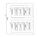
- the evaluation unit 113 includes a lane marking evaluation unit 113a and a road shoulder edge evaluation unit 113b.
- the lane marking evaluation unit 113a includes a reflection intensity change amount evaluation unit 81, a parallelism evaluation unit 82, a function approximation error amount evaluation unit 83, and a measurement condition evaluation unit 84.
- the road shoulder edge evaluation unit 113b includes a height change evaluation unit 91, a parallelism evaluation unit 92, a function approximation error amount evaluation unit 93, and a measurement condition evaluation unit 94.
- the configuration of the map editing device 20 according to the first embodiment will be described with reference to FIG.
- the map editing device 20 is a computer.
- the map editing device 20 includes hardware such as a processor 21, a memory 22, a storage 23, and a communication interface 24.
- the processor 21 is connected to other hardware via a signal line, and controls these other hardware.
- the map editing device 20 is connected to the input device 25 and the display device 26 via the communication interface 24.
- the map editing device 20 includes a display unit 211 and an editing unit 212 as functional components.
- the function of each functional component of the map editing device 20 is realized by software.
- the storage 23 stores a program that realizes the function of each functional component of the map editing device 20. This program is read into the memory 22 by the processor 21 and executed by the processor 21. As a result, the function of each functional component of the map editing device 20 is realized.
- the processors 11 and 21 are ICs (Integrated Circuits) that perform processing.
- the processors 11 and 21 are, as a specific example, CPUs (Central). Processing Unit), DSP (Digital Signal Processor), and GPU (Graphics Processing Unit).
- the memories 12 and 22 are storage devices that temporarily store data.
- the memories 12 and 22 are, for example, SRAM (Static Random Access Memory) and DRAM (Dynamic Random Access Memory).
- the storages 13 and 23 are storage devices that store data.
- the storages 13 and 23 are, for example, HDDs (Hard Disk Drives).
- the storages 13 and 23 are SD (registered trademark, Secure Digital) memory card, CF (CompactFlash, registered trademark), NAND flash, flexible disk, optical disk, compact disk, Blu-ray (registered trademark) disk, DVD (Digital Versatile Disk). ), Such as a portable recording medium.
- the communication interfaces 14 and 24 are interfaces for communicating with external devices.
- the communication interfaces 14 and 24 are, for example, Ethernet (registered trademark), USB (Universal Serial Bus), and HDMI (registered trademark, High-Definition Multimedia Interface) ports.
- the input device 25 is a device that receives an input from a user.
- the input device 25 is, for example, a keyboard or a mouse.
- the display device 26 is a device that displays information.
- the display device 26 is an LCD (Liquid Crystal Display).
- FIG. 2 only one processor 11 is shown. However, a plurality of processors 11 may be provided, and the plurality of processors 11 may execute the programs realizing the respective functions in cooperation with each other. Similarly, in FIG. 4, only one processor 21 is shown. However, a plurality of processors 21 may be provided, and the plurality of processors 21 may execute programs that implement respective functions in cooperation with each other.
- the operation of the map generation system 1 according to the first embodiment will be described with reference to FIGS. 5 to 26.
- the operation of the map generation system 1 according to the first embodiment corresponds to the map generation method according to the first embodiment.
- the operation of the map generation system 1 according to the first embodiment corresponds to the processing of the map generation program according to the first embodiment.
- the measurement information acquisition unit 111 of the map generation device 10 acquires the measurement information stored in the measurement information storage device 30.
- the measurement information is information obtained by measuring the periphery of the roadway by a measuring device mounted on the measurement vehicle while the measurement vehicle such as MMS travels on the roadway.
- the measuring device is, for example, a device such as a laser radar and a camera.
- the measurement information includes point cloud data, which is a plurality of point data representing the position of the feature around the road, obtained by the laser radar, and image data around the road obtained by the camera. Further, the measurement information includes movement trajectory information indicating the trajectory of the traveling position of the measurement vehicle.
- the measurement information also includes posture data indicating the posture of the measurement vehicle and calibration data indicating the position and posture of the measuring device.
- the traveling position of the measurement vehicle is specified based on the positioning signal received by the positioning antenna mounted on the measurement vehicle.
- the positioning antenna is, as a specific example, a GPS (Global Positioning System) antenna.
- the measurement information is not limited to the information obtained by the measurement device mounted on the measurement vehicle, and may be the information obtained by the measurement device mounted on another moving body such as an aircraft or a drone.
- the movement locus information is information indicating the locus of the position to which the moving body has moved.
- Step S12 of FIG. 5 plotting process
- the plotting unit 112 of the map generating device 10 generates linearization information indicating the end of the roadway based on the measurement information acquired in step S11. Specifically, the plotting unit 112 generates, as the linearization information indicating the end of the roadway, the linearization information indicating at least one of the lane markings and the shoulder edge of the roadway. The plotting unit 112 writes the linearization information in the primary map storage device 40.
- Step S13 of FIG. 5 evaluation process
- the evaluation unit 113 of the map generation device 10 calculates an evaluation value indicating the reliability of the position information of the partial information for each partial information forming the linearized information generated in step S12.
- the evaluation unit 113 writes the evaluation value in the primary map storage device 40 in association with the linearization information.
- the partial information is defined by dividing the linearization information at each branching point and confluence point of the roadway, or by dividing the linearization information at a constant distance (for example, every several meters to several hundred meters). It
- the reliability means the certainty of the position of the partial information.
- Step S14 of FIG. 5 display processing
- the display unit 211 of the map editing device 20 acquires the linearization information and the evaluation value stored in the primary map storage device 40.
- the display unit 211 displays the linearized information by displaying the partial information on the display device 26 connected via the communication interface 24 in different display modes according to the evaluation value.
- the display unit 211 displays the partial information whose reliability indicated by the evaluation value is lower than the threshold in a display mode different from that of the other partial information.
- the display unit 211 displays partial information whose reliability is lower than the threshold value in a color or line type different from that of other partial information.
- Step S15 of FIG. 5 editing process
- the editing unit 212 of the map editing apparatus 20 receives the input of the editing information for the linearization information displayed in step S14.
- the editing unit 212 edits the linearization information according to the editing information.
- the editing unit 212 writes the edited linearization information in the secondary map storage device 50.
- the editing unit 212 receives the edit information input by the user operating the input device 25.
- the editing unit 212 edits the linearization information according to the editing information each time the editing information is received.
- the editing unit 212 writes the edited linearization information in the secondary map storage device 50.
- the candidate point extraction unit 114 divides the point cloud data included in the measurement information into a plurality of plate-shaped cross-sectional areas perpendicular to the traveling direction of the measurement vehicle.
- the traveling direction of the measurement vehicle can be specified from the trajectory indicated by the movement trajectory information.
- the movement track information is composed of, for example, position information of the measurement vehicle every 0.1 seconds.
- the candidate point extraction unit 114 sets a plurality of plate-shaped cross-sectional areas perpendicular to the traveling direction of the measurement vehicle.
- the candidate point extraction unit 114 specifies the point cloud data included in the target cross-sectional area by performing a spatial search for each cross-sectional area.
- the laser radar may perform measurement while rotating in a direction perpendicular to the traveling direction of the measurement vehicle.
- the range measured by one rotation of the laser radar may be taken as one cross sectional area, and the data for one rotation may be treated as the data of one cross sectional area.
- the data for one revolution is not a precise cross-section data, but spiral data.
- MMS spatial information is acquired by a laser radar that rotates a measurement direction on a certain axis.
- the candidate point extraction unit 114 may set the cross-sectional area at regular intervals in the traveling direction of the measurement vehicle. That is, a constant space may be provided between the cross-sectional areas.
- Step S22 of FIG. 6 candidate point extraction processing
- the candidate point extraction unit 114 extracts, as the candidate point data, a plurality of point data that may indicate the end of the roadway from the point cloud data of the target cross sectional area for each cross sectional area divided in step S21. .. Specifically, the candidate point extraction unit 114 extracts, as candidate point data, point data that may represent at least one of a lane line representing the end of the roadway and a road shoulder edge.
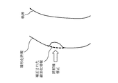
- the candidate point extracting unit 114 specifies, in the point data on the road surface, a location where the reflection intensity changes as the lane marking range.
- the point data is acquired by a measuring device such as a laser radar, the point data has the position of the reflection point and the reflection intensity when reflected at the reflection point.
- the candidate point extraction unit 114 specifies the point data of the center of gravity where the reflection intensity is higher than a certain value by a certain value as compared with the surroundings, as the point data that is highly likely to represent a lane marking.
- the point data on the road surface can be specified from the height of the point data. In FIG.
- the vertical axis represents the reflection intensity of the point data
- the horizontal axis represents the right direction of the road in the cross sectional area.
- the right direction of the road is a direction that is perpendicular to both the traveling direction of the vehicle and the vertically upward direction, and that the right side of the vehicle toward the traveling direction is positive.
- the coordinate origin may be taken anywhere, in the first embodiment, the vertical axis is 0 [W / sr / m 2 ] as the origin position, and the horizontal axis is the point data included in the point group data in the plane and represents the road. The position of the point data with the smallest rightward coordinate value is the origin position.
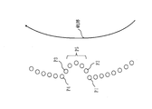
- the candidate point extraction unit 114 sequentially examines the reflection intensity from the point data included in the point cloud data in which the coordinate value in the right direction of the road is small, and the point data in which the reflection intensity sharply increases, that is, the immediately preceding point data.
- a predetermined value for example, the set value of the reflection intensity displacement of the reflected light of the laser light
- the point data Y for which the difference in reflection intensity from the data is larger than a predetermined value is specified.
- a plurality of point data with high reflection intensity that is, the center of gravity of the plurality of point data from the point data X to the point data Y
- the candidate point data Z is specified by using the position as a candidate element of the lane marking. If the point data exists at the position of the center of gravity, the point data is used as the candidate point data, and if the point data does not exist, new point data is generated as the candidate point data.
- the center position of the point data X and the point data Y may be set as the candidate line data for the marking line.
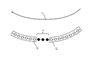
- the method of identifying candidate point data of lane markings does not use the difference in the reflection intensity from the adjacent point data as described above, but instead sets the threshold th1 in advance for the reflection intensity as shown in FIG.
- the point data P1, the point data P2, the point data P3, and the point data P4 that are set and are included in the point cloud data and are equal to or larger than the threshold value th1 are extracted, and the plurality of extracted point data are set as the lane marking range, When the width is within the specified upper and lower limit width, these barycentric positions may be used as the candidate point data Z of the marking line.
- the candidate point extraction unit 114 points to the point data on the road surface and the point data of the installation object based on the height of the point data, as shown in FIG. Classify group data.
- the candidate point extraction unit 114 specifies the point data that is closest to the locus indicated by the movement locus information among the point data of the installation object as the point data that is likely to represent the shoulder edge.
- FIG. 9 assumes a case where there is an installation such as a guardrail.
- the vertical axis represents the height direction in the cross-sectional area, that is, the vertically upward direction
- the horizontal axis represents the right direction of the road in the cross-sectional area.
- the origin of coordinates may be taken anywhere, but in the first embodiment, the vertical axis is the origin position which is the lowest point data among the point data included in the point group data in the plane, and the horizontal axis is the plane.
- the position of the point data included in the point cloud data of the point data having the smallest coordinate value in the right direction of the road is the origin position.
- the candidate point extraction unit 114 first classifies the point cloud data into point data on the road and point data of features other than the road such as curbs and installations. This classification is performed by setting a threshold value th2 in the height direction in advance, and setting point data below the threshold value th2 as roads and point data above the threshold value th2 as point data other than roads.
- the point data closest to the locus indicated by the movement locus information is extracted.
- the locus is not shown in the example of FIG. 9, since the locus is located on the left of the origin, the point data P1 is extracted as the point data closest to the locus.
- the candidate point extraction unit 114 specifies the position of the foot of the perpendicular line that descends from the position of the extracted point data P1 to the road surface as the candidate point data P2 of the road shoulder edge.
- the road surface may be preset in the same manner as the threshold value th2, or an approximate plane is generated from a plurality of point data determined as point data on the road that is less than the threshold value th2, and the generated plane is generated. May be used as the road surface.
- the road shoulder is a boundary indicating the end of the road, and only one road shoulder is used as map information on the left and right with respect to the traveling direction of the vehicle. Therefore, the candidate point extracting unit 114 specifies only one left and right candidate point data for the road shoulder edge in one cross-sectional area with respect to the traveling path of the vehicle. As a result, the point sequence of the candidate point data of the roadside edges arranged in the vehicle traveling direction is specified.
- the method of identifying the candidate point data of the road shoulder edge is not limited to the above method, and for example, among the point data included in the point cloud data, the point data having a higher coordinate value in the right direction of the road is smaller in order of the point data. It is also possible to examine the coordinate values in the vertical direction and extract the point data where the coordinate values suddenly decrease and the point where the coordinate values suddenly increase, and use these as the shoulder point candidate point data. Further, as shown in FIG. 10, when the outside of the road shoulder is inclined such as a bank and the point cloud data is rough, the approximate straight line L1 is calculated based on a plurality of point data whose height changes rapidly. May be generated, and the intersection of this straight line and the road surface may be used as the candidate point data Z for the road shoulder edge.
- Step S23 of FIG. 6 grouping process
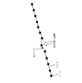
- the candidate point connection unit 115 divides the candidate point data extracted from each cross-sectional area into groups of candidate point data representing the same lane marking or the same road shoulder edge.
- the candidate point connection unit 115 divides the candidate point data into groups based on the position.
- the candidate point connection unit 115 divides the candidate point data into groups in consideration of both the distance between the candidate point data and the trajectory indicated by the movement trajectory information and the distance between the candidate point data.
- the candidate point connecting unit 115 groups the two candidate point data of interest so that the candidate point data having a short distance between the loci and the short distance between the candidate point data are in the same group. Divide.
- the candidate point connection unit 115 multiplies the distance between the candidate point data by a smaller weight as the distance between the candidate point data that is farther in the direction closer to the locus increases, and the candidate points that are farther in the direction closer to the locus are separated.
- the distance between the candidate point data is multiplied by a larger value for the data, and the candidate point data whose weighted distance is within the reference value are grouped together. For example, suppose that there are candidate point data X, Y, Z as shown in FIG. The distance between the candidate point data X and the candidate point data Y and the distance between the candidate point data X and the candidate point data Z are substantially the same.
- the two candidate point data X and the candidate point data Y located on the same white line have almost the same distance from the locus, whereas the candidate point data X and the candidate point data Z located on different white lines are the same.
- the locus is a sequence of points indicating the position of the vehicle at each time. Therefore, in practice, the distance between each candidate point data of the marking line and each point included in the point sequence of the trajectory is calculated, and the distance between the candidate point data of the trajectory and the point data of the trajectory closest to each other is calculated as the distance of the marking line. It is the distance between the candidate point data and the locus.
- a perpendicular line may be drawn from each candidate point data to the curve, and the length of the perpendicular line may be calculated as the distance between the candidate point data of the division line and the locus.
- the method of grouping the lane markings is not limited to the above, and the difference between the distance between the two candidate point data and the locus is not calculated for the two candidate point data, and the absolute value of the distance from the locus is within a predetermined range.
- the candidate point data of may be grouped.
- the candidate point connection unit 115 divides the group into groups only when the distance to the trajectory changes significantly when generating the linearized information of the sequence of constituent points that form the road shoulder edge, and otherwise, to the left of the measurement vehicle. Group by the right or left side only.
- the point cloud data may not be accurately measured due to the influence of plants and parallel vehicles.
- all candidate point data can be distinguished by being located on the left or right of the trajectory. Since it is simply distributed to one of the two groups, there is a possibility that a road shoulder edge having a large unevenness in the left and right direction and not smooth, that is, a road shoulder edge deviating from the actual shape of the road shoulder edge is generated.
- a section in which the arrangement of the candidate point data has a large unevenness in the left-right direction may be determined to be erroneous detection, and the candidate point data included in the section determined to be erroneous detection may be excluded from the candidate point data.
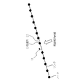
- the candidate point connection unit 115 compares the group of candidate point data with the shape of the trajectory. Specifically, the candidate point connection unit 115 calculates the distance between each candidate point data in the group and the locus, and extracts the point data whose distance changes from the adjacent candidate point data by a predetermined threshold value or more. ..
- the point cloud data could not be accurately acquired by the laser due to the influence of plants and parallel running vehicles, and the location where there is candidate point data that is likely to generate a shoulder edge that deviates from the actual shape of the shoulder edge is detected.
- the candidate point data corresponding to the traveling locus can be selected. As a result, it is possible to eliminate the disturbance factors such as dirt on the road surface and select the candidate point data used for generating the boundary.
- the candidate point connection unit 115 checks the distance between each candidate point data and the locus in order from the point data with earlier measurement time to the point data with later measurement time. Go Then, the candidate point connection unit 115 has point data whose distance to the trajectory changes abruptly, that is, candidate point data P1 in which the distance between the next candidate point data P2 and the trajectory decreases rapidly.
- candidate point data P1 in which the distance between the next candidate point data P2 and the trajectory decreases rapidly.
- the previous candidate point data P3 and the candidate point data P4 in which the distance between the locus and the trajectory rapidly increases are specified.
- the candidate point data P1 and the candidate point data P4 are ends of the correctly identified candidate point data, and the plurality of points between the candidate point data P2 and the candidate point data P3 and between the candidate point data P2 and the candidate point data P3.
- the candidate point data P5 is a false detection. Therefore, the candidate point data P2 and the candidate point data P3 and the plurality of candidate point data P5 are excluded from the candidate point data used to generate the position information of the road shoulder edge.
- the candidate point connection unit 115 uses the candidate point data belonging to the same group as a node, and connects the nodes by a link in the traveling direction of the measurement vehicle to configure at least one of a lane line and a road shoulder edge. Generate linearization information. Specifically, the candidate point connection unit 115 connects the nodes, which are the candidate point data located at the closest positions among the candidate point data belonging to the same group, by a link.
- the candidate point connection unit 115 multiplies the distance between the candidate point data by a smaller weight as the distance between the candidate point data that is farther in the direction closer to the locus increases, and the candidate points that are farther in the direction closer to the locus become perpendicular.
- the distance between the candidate point data is multiplied by the weight of a larger value for the data.
- the candidate point connection unit 115 sequentially connects from the node of the candidate point data in the front cross-sectional area in the traveling direction of the measurement vehicle to the node of the candidate point data within the weighted distance threshold value by a link. .. Since the nodes of the candidate point data within the threshold are connected by the link, there is a possibility that linearization information that is partially discontinuous is generated.
- the candidate point connection unit 115 may connect linearization information generated from different groups. For example, as shown in FIG. 13, the candidate point connection unit 115 connects pieces of linearized information whose positional relationship is close to the locus with a link parallel to the locus or close to parallel. As a result, even if the road is curved, it is possible to generate linearization information along the curve of the road.
- the candidate point connection unit 115 calculates the barycentric position of the candidate point data included in the group, and calculates the distance between the barycenter of one group and the candidate point data included in another group.
- the candidate point connection unit 115 extracts several candidate point data in order from the smallest distance.
- the candidate point connection unit 115 reverses the roles of the groups and extracts some candidate point data from the opposite group.
- the candidate point connection unit 115 calculates the barycentric positions of the plurality of extracted candidate points in each group, and calculates the distance between the barycenters.
- the candidate point connecting unit 115 connects the two groups if the distance between the centers of gravity is within a predetermined range.
- the locus T is used to connect the group of demarcation lines g1 and the group g2. If the group g1 and the group g2 are within a range of a predetermined distance, a plurality of candidate point data S are generated so as to connect these two groups. The plurality of candidate point data S are generated so that an approximate curve formed by the group g1 and the group g2 and the plurality of candidate point data S has a similar shape to the trajectory T.
- the locus is a sequence of points indicating the position of the measurement vehicle. Therefore, the candidate point connection unit 115 generates an approximate curve from the sequence of points representing the locus, and the approximate curve is similar to the approximate curve generated by the two groups and the newly generated candidate point data.
- the method of connecting the two groups is not limited to the above method, and the groups may be connected only by using the positional relationship of the point sequence representing the locus without generating the approximate curve. For example, a new candidate point is made so that the angle formed by connecting the points of the point sequence representing the locus with a straight line is the same as the angle formed by connecting the newly generated candidate point data between the two groups with a straight line. You may generate data and connect groups.
- Step S25 of FIG. 6 correction process
- the correction unit 116 corrects the linearization information generated in step S24 to generate highly reliable linearization information. Specifically, the correction unit 116 performs the following three corrections, correction 1 to correction 3.
- the correction unit 116 writes the corrected linearization information in the primary map storage device 40.
- the correction unit 116 targets the linearization information having a length equal to or shorter than the first reference distance (for example, 10 meters) of the linearization information generated by the candidate point connection unit to the side opposite to the locus. , If there is other linearization information longer than the target linearization information, the target linearization information is deleted. That is, the correction unit 116 deletes the linearization information in which other linearization information that is long on the opposite side of the locus exists as road markings rather than lane markings.
- the candidate point connection unit 115 divides the group only when the distance to the locus significantly changes when generating the linearization information of the component point sequence that forms the road shoulder edge, and otherwise measures. Group only by the left or right side of the vehicle. Therefore, there is a possibility that the linearized information indicating the road shoulder edge may be linearized information with rattling or discontinuous linearized information. Since such linearized information may be erroneously detected by plants or parallel running vehicles, it is corrected. Even if the process of excluding the candidate point data included in the section determined to be erroneously detected from the candidate point data in step S23, the linearization information is still generated from the erroneously detected candidate point data. There is a possibility.
- the correction unit 116 targets the section information that constitutes a part of the linearization information as compared with other section information that is adjacent both before and after the target section information and has a second reference distance (for example, 2 meters). ) If the distance is closer to the locus side, the target section information is deleted. That is, when a part of the linearization information section once moves to the locus side by the second reference distance or more and then returns to the vicinity of the original position, the correction section 116 affects the section due to the blockage by the parallel running vehicle. It is determined that the shielded section has been received and is deleted. In this case, as shown in FIG.
- the correction unit 116 sets the section information before the deleted section information and the section information subsequent to the deleted section information in the traveling direction parallel to the trajectory. Connect by link and regenerate deleted section information. (Correction 3)
- the correction unit 116 targets the section information at intervals of about 10 meters that forms part of the linearization information, and approximates a point curve forming the target section information to a cubic function and the target section.
- the target section information is deleted. That is, when a part of the linearized information has rattling exceeding the reference, the correction unit 116 deletes the section because it is affected by plants and the like. That is, a normal road shoulder edge can be generally expressed by a cubic function.
- the correction unit 116 regenerates the deleted section information by connecting only point data close to the locus forming the deleted section information by a link.
- the shoulder edge moves toward the center of the road. If the road edge indicated by the linearization information is located outside the actual road edge, the possibility that the vehicle will contact the road edge increases. However, since the road edge indicated by the linearization information moves closer to the center of the road, it is possible to reduce the possibility that the vehicle will come into contact with the road edge when the vehicle travels based on this linearization information.
- step S13 in FIG. 5 The evaluation process according to the first embodiment (step S13 in FIG. 5) will be described with reference to FIGS. 18 to 20.
- a case where the linearization information represents a lane marking will be described with reference to FIG. (Step S31 of FIG. 18: division processing)
- the lane marking evaluation unit 113a divides the linearization information for each piece of partial information forming the linearization information.
- the lane marking evaluation unit 113a calculates an evaluation value indicating the reliability of the position of the lane marking indicated by each piece of partial information. Specifically, the reflection intensity change amount evaluation unit 81, the parallelism evaluation unit 82, the function approximation error amount evaluation unit 83, and the measurement condition evaluation unit 84 use the method described below to determine the position of the division line indicated by the partial information. An evaluation value indicating the reliability of is calculated.
- the reflection intensity change amount evaluation unit 81 obtains the reflection intensity change amount (see FIG. 7) which is the difference between the reflection intensity of the portion extracted as the lane marking and the reflection intensity of the surrounding area, and determines the magnitude of the reflection intensity change amount. evaluate. If the amount of change in the reflection intensity is large, it is considered that the position of the demarcating line can be clearly acquired. Therefore, the greater the amount of change in the reflection intensity, the greater the amount of change in the reflection intensity is. To raise.
- the evaluation item is the difference between the reflection intensity of the location extracted as the lane marking and the surrounding reflection intensity, but the absolute value of the reflection intensity of the location extracted as the lane marking may be used as the assessment item.
- the parallelism evaluation unit 82 evaluates the parallelism between the arrangement direction of the marking line constituent points and the movement trajectory of the measurement vehicle. As shown in FIG. 19, when the arrangement line of the lane markings is not parallel to the movement locus of the measurement vehicle, it is highly likely that a stop line or other road markings were erroneously extracted as the lane markings, so the parallelism evaluation is performed. The unit 82 lowers the evaluation value of the position information of the lane markings.
- the function approximation error amount evaluation unit 83 evaluates the magnitude of the error amount sum when the lane line constituent points are approximated by a cubic function by the least square method. Since the error amount represents the degree of linear rattling, the function approximation error amount evaluation unit 83 increases the evaluation value of the lane marking position information as the error amount sum is smaller.
- the approximation method is not limited to the cubic function approximation.
- the measurement condition evaluation unit 84 uses the distance between the position of the measurement vehicle at the time when the measurement device acquires the measurement information used for estimating the lane marking and the lane marking constituting point, and the lane marking estimation.
- the evaluation value of the position information of the lane markings is obtained from the weather when the measurement device acquires the obtained measurement information. For example, if the lane marking line is far from the measurement vehicle, the data density is low, and the reliability of the data is low. Lower the evaluation value of. Further, in bad weather such as rainy weather, the reliability of the data acquired by the measuring device decreases, so that the measurement condition evaluating unit 84 determines that the weather condition at the time of acquiring the measurement information is poor, and the measurement condition evaluating unit 84 determines the position of the lane markings. Lower the evaluation value of information.
- the marking line evaluation unit 113a combines the evaluation values calculated by the reflection intensity change amount evaluation unit 81, the parallelism evaluation unit 82, the function approximation error amount evaluation unit 83, and the measurement condition evaluation unit 84 in step S32, Calculate the rating of information.
- the lane marking evaluation unit 113a weights the evaluation values calculated by the reflection intensity change amount evaluation unit 81, the parallelism evaluation unit 82, the function approximation error amount evaluation unit 83, and the measurement condition evaluation unit 84. And calculate the evaluation value of the partial information.
- the lane marking evaluation unit 113a writes the evaluation value of the partial information in the primary map storage device 40 in association with the partial information.
- the lane marking evaluation unit 113a also corresponds to the partial information with the evaluation values calculated by the reflection intensity change amount evaluation unit 81, the parallelism evaluation unit 82, the function approximation error amount evaluation unit 83, and the measurement condition evaluation unit 84.
- the data may be written in the primary map storage device 40.
- the road shoulder edge evaluation unit 113b divides the linearization information into pieces of partial information that form the linearization information.
- the road shoulder edge evaluation unit 113b calculates an evaluation value indicating the reliability of the position of the road shoulder edge indicated by each piece of partial information. Specifically, the height change evaluation unit 91, the parallelism evaluation unit 92, the function approximation error amount evaluation unit 93, and the measurement condition evaluation unit 94 use the method described below to determine the position of the road shoulder edge indicated by the partial information. An evaluation value indicating the reliability is calculated.
- the height change evaluation unit 91 obtains an altitude difference (step) between the area extracted as the road shoulder edge and its surroundings, and evaluates the magnitude of the altitude difference. If the altitude difference is large, it is considered that the clear road shoulder edge position can be acquired. Therefore, the height change evaluation unit 91 increases the evaluation value of the road shoulder edge position information as the altitude difference increases.
- the altitude difference between the location extracted as the road shoulder edge and its surroundings was used as an evaluation item.
- the magnitude of the slope of the altitude change at the boundary between the location extracted as the road shoulder edge and its surroundings, that is, the slope May be used as an evaluation item.
- the parallelism evaluation unit 92, the function approximation error amount evaluation unit 93, and the measurement condition evaluation unit 94 are the same methods as the parallelism evaluation unit 82, the function approximation error amount evaluation unit 83, and the measurement condition evaluation unit 84 of the lane marking evaluation unit 113a. Then, the position information of the road shoulder edge is evaluated.
- the parallelism evaluation unit 92 evaluates the parallelism of the arrangement of the roadside edge constituent points with respect to the movement trajectory of the measurement vehicle. If the arrangement of the roadside edge constituent points is not parallel to the movement locus of the measurement vehicle, there is a high possibility that road irregularities or the like have been erroneously extracted as the roadside edges, so the parallelism evaluation unit 92 evaluates the position information of the roadside edges. Lower the value.
- the function approximation error amount evaluation unit 93 evaluates the size of the error amount sum when the arrangement of the road edge composing points is approximated by a cubic function by the least square method. As this value is smaller, the function approximation error amount evaluation unit 93 increases the evaluation value of the road shoulder edge position information.
- the measurement condition evaluation unit 94 is used for estimating the distance between the position of the measurement vehicle at the time when the measurement device acquires the measurement information used for estimating the road shoulder and the road shoulder edge constituent point, and for estimating the road shoulder edge.
- the evaluation value of the position information of the shoulder edge is obtained from the weather when the measuring device acquires the measured information. For example, if the road shoulder edge configuration point is farther from the measurement vehicle, the data density becomes lower, and the reliability of the data is reduced. Therefore, the measurement condition evaluation unit 94 determines that the road shoulder edge location information is the farther the road shoulder edge configuration point is from the measurement vehicle. Lower the evaluation value of. Further, in bad weather such as rain, the reliability of the data acquired by the measuring device decreases, so the measurement condition evaluation unit 94 lowers the evaluation value of the positional information of the road shoulder edge as the weather during measurement information acquisition is poor. ..
- Step S43 of FIG. 20 comprehensive evaluation process
- the roadside edge evaluation unit 113b integrates the evaluation values calculated by the height change evaluation unit 91, the parallelism evaluation unit 92, the function approximation error amount evaluation unit 93, and the measurement condition evaluation unit 94 in step S42 to obtain partial information. Calculate the evaluation value of.
- the road shoulder edge evaluation unit 113b weights the evaluation values calculated by the height change evaluation unit 91, the parallelism evaluation unit 92, the function approximation error amount evaluation unit 93, and the measurement condition evaluation unit 94. The sum is calculated to calculate the evaluation value of the partial information.
- the roadside edge evaluation unit 113b writes the evaluation value of the partial information in the primary map storage device 40 in association with the partial information.
- the road shoulder edge evaluation unit 113b also associates the evaluation values calculated by the height change evaluation unit 91, the parallelism evaluation unit 92, the function approximation error amount evaluation unit 93, and the measurement condition evaluation unit 94 with the partial information. May be written in the primary map storage device 40.
- Step S14 in FIG. 5 The display process according to the first embodiment (step S14 in FIG. 5) will be described with reference to FIGS. 21 and 22.
- Step S51 of FIG. 21 information acquisition process
- the display unit 211 acquires the linearization information stored in the primary map storage device 40 and the evaluation value for each piece of partial information forming the linearization information.
- Step S52 of FIG. 21 linearized information display process
- the display unit 211 displays the linearized information by displaying the partial information on the display device 26 connected via the communication interface 24 in different display modes according to the evaluation value. At this time, the display unit 211 superimposes and displays other point cloud data on the nodes and links that form the linearization information. Specifically, as shown in FIG. 22, the display unit 211 identifies the partial information having the evaluation value lower than the threshold value, from the partial information forming the linearization information. The display unit 211 displays the partial information other than the specified partial information, that is, the partial information whose evaluation value is equal to or more than the threshold value in the first display mode, and displays the specified partial information, that is, the partial information whose evaluation value is lower than the threshold value.
- the second display mode different from the first display mode is displayed.
- the partial information whose evaluation value is equal to or larger than the threshold value is shown by a solid line
- the partial information whose evaluation value is lower than the threshold value is shown by a broken line.
- the display unit 211 displays partial information whose evaluation value is equal to or greater than a threshold value in blue and displays partial information whose evaluation value is lower than the threshold value in red, or partial information whose evaluation value is lower than the threshold value and whose evaluation value is the threshold value.
- the information may be displayed by blinking.
- the display unit 211 may display the partial information in different display modes depending on the degree of reliability indicated by the evaluation value. For example, the display unit 211 may display the partial information in different colors according to the degree of reliability indicated by the evaluation value. The display unit 211 may display the partial information with higher brightness as the reliability indicated by the evaluation value is lower.
- the display unit 211 may display the corrected partial information in a display mode different from that of the other partial information in step S25 of FIG. At this time, the display unit 211 may display the corrected partial information in different display modes depending on the correction contents, for example, correction 1 to correction 3.
- the editing process (step S15 in FIG. 5) according to the first embodiment will be described with reference to FIGS. 23 to 28.
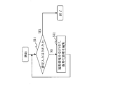
- Step S61 of FIG. 23: confirmation determination process The editing unit 212 determines whether a confirmation input for confirming the linearization information has been made. Specifically, the editing unit 212 determines whether or not the user has operated the input device 25 to input a confirmation. For example, the editing unit 212 determines that the confirmation input has been made when the confirmation button indicating the end of editing is pressed by the user. When the confirmation input is made, the editing unit 212 writes the linearization information in the secondary map storage device 50 and ends the process. On the other hand, when the confirmation input is not made, the editing unit 212 advances the process to step S62.
- the editing unit 212 receives the input of the editing information for changing the position of at least one of the node and the link forming the linearization information. Upon receiving the editing information, the editing unit 212 edits the linearization information according to the editing information. Specifically, the editing unit 212 receives the designation of the portion to be edited in the linearization information. For example, when the mouse that is the input device 25 is clicked, the editing unit 212 receives the periphery of the clicked position as a target portion. Then, as shown in FIG. 24, the display unit 211 magnifies the designated portion and sets the nodes and links forming the linearization information in the designated portion and the point cloud data in the three-dimensional coordinate system.
- the editing unit 212 receives an input of editing information for editing the positions of the enlarged-displayed nodes and links. For example, a node is dragged by the mouse that is the input device 25 and dropped at the destination. Then, the editing unit 212 changes the position of the dragged node to the dropped position, and changes the position of the link connected to the dragged node according to the movement of the node.
- the node X shown in FIG. 24 is dragged and dropped at the position P, the node X is changed to the position P and the links L1 and L2 connected to the node X are accordingly changed as shown in FIG. The position of is changed.
- the display unit 211 may change the display angle at which the nodes and links and the point cloud data are displayed according to the user's operation. That is, the display unit 211 may display the nodes and links and the point cloud data from different viewpoints according to the user's operation.
- the editing unit 212 may accept not only edit information for changing the position of at least one of a node and a link but also edit information for adding a new link. For example, as shown in FIG. 26, it is assumed that a part of the dividing line is rubbed and cut off. In this case, the editing unit 212 receives the input of the edit information for adding a new link, and connects the lane markings by adding the link as shown in FIG.
- the display unit 211 may display the image information obtained by the camera about the portion to be edited and its surroundings separately from the linearization information and the point cloud information. As a result, the user can perform the editing work while confirming the state of the marking line or the shoulder edge based on the image information.
- the display unit 211 may change the display mode of the partial information edited by the editing unit 212. For example, when the editing unit 212 edits partial information whose evaluation value is lower than the threshold value, the display unit 211 displays the edited partial information in the same display mode as the partial information whose evaluation value is equal to or higher than the threshold value. To do.
- the partial information of the linearization information is displayed in different display modes according to the evaluation value. This makes it possible to easily identify a portion of the linearization information that is likely to be erroneous. Therefore, it is possible to efficiently perform error correction on the linearized information manually.
- the part to be edited is enlarged and the part to be edited is displayed on the screen on which the grid lines representing the three-dimensional coordinate system are displayed. This facilitates the user to appropriately edit the linearization information generated by the plotting unit 112.
- the plotting unit 112 identifies the position of another road feature such as a sign around the roadway, a road marking, and a stop line based on the measurement information, and identifies the other road feature identified. You may generate the vector data showing.
- the plotting unit 112 writes the vector data in the primary map storage device 40.
- the evaluation unit 113 calculates an evaluation value indicating the reliability of the vector data.
- the display unit 211 displays the vector data in a different display mode according to the evaluation value together with the linearization information, and the editing unit 212 receives the input of the editing information about the vector data.
- the map generation device 10 includes an electronic circuit 15 instead of the processor 11, the memory 12, and the storage 13.
- the electronic circuit 15 is a dedicated circuit that realizes the functional components of the map generating device 10 and the functions of the memory 12 and the storage 13.
- the map editing device 20 includes an electronic circuit 27 instead of the processor 21, the memory 22 and the storage 23.
- the electronic circuit 27 is a dedicated circuit for realizing the functional components of the map editing device 20 and the functions of the memory 22 and the storage 23.
- the electronic circuits 15 and 27 include a single circuit, a composite circuit, a programmed processor, a parallel programmed processor, a logic IC, a GA (Gate Array), an ASIC (Application Specific Integrated Circuit), and an FPGA (Field-Programmable Gate Array). Is assumed.
- the function of each functional constituent element of the map generating device 10 may be realized by one electronic circuit 15, or the function of each functional constituent element may be distributed to a plurality of electronic circuits 15 and realized.
- the function of each functional constituent element may be realized by one electronic circuit 27, or the function of each functional constituent element may be distributed to a plurality of electronic circuits 27 and realized. ..
- ⁇ Modification 3> As a third modification, some functions may be realized by hardware and other functions may be realized by software. That is, of the functional components, some of the functions may be realized by hardware, and other functions may be realized by software.
- the processors 11 and 21, the memories 12 and 22, the storages 13 and 23, and the electronic circuits 15 and 27 are called processing circuits. That is, the function of each functional component is realized by the processing circuit.
- Embodiment 2 differs from the first embodiment in that partial information having a low evaluation value is divided into groups according to the cause of the low evaluation value. In the second embodiment, these different points will be described, and description of the same points will be omitted.
- the configuration of the map editing device 20 according to the second embodiment will be described with reference to FIG.
- the map editing apparatus 20 according to the second embodiment differs from the map editing apparatus 20 according to the first embodiment in that a map information classifying unit 213 is provided.
- the graphical information classification unit 213 divides the partial information having a low evaluation value into groups according to the cause of the low evaluation value. Specifically, the graphical information classification unit 213 classifies the partial information having a low evaluation value according to which evaluation item of the plurality of evaluation items has a low evaluation value.
- the evaluation item is an item evaluated by each of the reflection intensity change amount evaluation unit 81, the parallelism evaluation unit 82, the function approximation error amount evaluation unit 83, and the measurement condition evaluation unit 84 if it is a lane marking, and the road shoulder edge. If so, the height change evaluation unit 91, the parallelism evaluation unit 92, the function approximation error amount evaluation unit 93, and the measurement condition evaluation unit 94 are items to be evaluated.
- the graphical information classifying unit 213 groups lane lines.
- the graphical information classification unit 213 extracts, from the map information, lane lines whose positional information reliability is equal to or lower than a certain level.
- the graphical information classification unit 213 corresponds the extracted lane markings to, for example, a first group that is a group of lane markings whose evaluation value of the error amount of the function approximation is a certain value or less, and the first group.
- the second group which is a group of lane markings whose parallel evaluation value with respect to the movement trajectory of the measurement vehicle is a certain value or less, and the first and second groups, which do not correspond to the evaluation of the change amount of the reflection intensity
- a third group which is a group of lane markings whose value is a certain value or less, and a third group, which does not correspond to the first, second, and third groups, and whose valuation value of the measurement condition is a certain value or less. It is classified into four groups.
- the display unit 211 can switch the screen display so that partial information belonging to the same group is continuously displayed.
- 31 and 32 show transition examples of screens when the partial information belonging to the same group is continuously displayed.
- the user operates the input device 25 as shown in FIGS. 31 and 32, and the partial information in which the evaluation value of the position information is lowered due to the same cause on the screen of the display device 26 (partition line represented by a thick line).
- the screen display can be switched so that is continuously displayed.
- Embodiment 3 is different from the first and second embodiments in that the evaluation value calculated based on the presence / absence of correction in the past is changed. In the third embodiment, these different points will be described, and description of the same points will be omitted.
- the configuration of the map generation device 10 according to the third embodiment will be described with reference to FIG.
- the map generating apparatus 10 according to the third embodiment is different from the map generating apparatuses 10 according to the first and second embodiments in that the evaluation unit 113 includes an evaluation function learning unit 117.
- the evaluation function learning unit 117 learns the correspondence between the evaluation values of the plurality of evaluation items for the partial information and the presence / absence of correction of the partial information by the map editing device 20. Then, the evaluation function learning unit 117 lowers the overall evaluation value of the partial information in which the evaluation value of each evaluation item is similar to the partial information modified in the past, and reduces each evaluation item in the partial information that has not been modified in the past.
- the evaluation method for calculating the comprehensive evaluation value is modified so that the comprehensive evaluation value of the partial information having similar evaluation values becomes higher.
- the comprehensive evaluation value is the evaluation value calculated in step S33 of FIG. 18 and step S43 of FIG.
- partial information having a low evaluation value of the evaluation item A (graphic data numbers 2 and 3) or partial information having a low evaluation value of the evaluation item values B and C (graphic data numbers 6 and 8)
- the evaluation function learning unit 117 learns this tendency, the lane marking evaluation unit 113a and the road shoulder edge evaluation unit 113b, for example, as illustrated in FIG. 35, partial information (chart data number 12) in which the evaluation value of the evaluation item A is low, Also, the comprehensive evaluation value for the partial information (graphic data number 14) for which the evaluation values of the evaluation item values B and C are both low is lowered.
- map generation system 10 map generation device, 11 processor, 12 memory, 13 storage, 14 communication interface, 15 electronic circuit, 111 measurement information acquisition unit, 112 plotting unit, 113 evaluation unit, 113a lane marking evaluation unit, 113b shoulder Edge evaluation unit, 114 candidate point extraction unit, 115 candidate point connection unit, 116 correction unit, 117 evaluation function learning unit, 20 map editing device, 21 processor, 22 memory, 23 storage, 24 communication interface, 25 input device, 26 display Device, 27 electronic circuit, 211 display unit, 212 editing unit, 213 graphical information classification unit, 30 measurement information storage device, 40 primary map storage device, 50 secondary map storage device, 60 transmission line, 70 transmission line, 70 transmission line, 81 reflection Strength change amount evaluation section, 82 parallelism evaluation Parts, 83 function approximation error amount evaluation unit, 84 measurement condition evaluation unit, 91 height change evaluation unit, 92 parallel evaluating section, 93 function approximation error amount evaluation unit, 94 measurement condition evaluation unit.
Landscapes
- Engineering & Computer Science (AREA)
- General Physics & Mathematics (AREA)
- Physics & Mathematics (AREA)
- Theoretical Computer Science (AREA)
- Computer Vision & Pattern Recognition (AREA)
- Radar, Positioning & Navigation (AREA)
- Remote Sensing (AREA)
- Multimedia (AREA)
- Automation & Control Theory (AREA)
- Educational Technology (AREA)
- Educational Administration (AREA)
- Business, Economics & Management (AREA)
- Processing Or Creating Images (AREA)
- Traffic Control Systems (AREA)
- Instructional Devices (AREA)
- Navigation (AREA)
Abstract
地図生成装置(10)は、計測装置によって得られた車道の周辺の計測情報に基づき、車道の区画線と路肩縁との少なくともいずれかを表す線形化情報を生成する。地図生成装置(10)は、線形化情報を構成する部分情報毎に、部分情報の信頼度を示す評価値を計算する。地図編集装置(20)は、評価値に応じて異なる表示態様で部分情報を表示することにより、線形化情報を表示する。地図編集装置(20)は、表示された線形化情報に対する編集情報の入力を受け付ける。
Description
この発明は、計測装置によって得られた車道の周辺の計測情報に基づき、車道の区画線と路肩縁といった情報を生成する技術に関する。
近年、自動走行車の開発が進められている。自動走行の実現には、自動走行車に取り付けられるカメラとレーザレーダといった様々なセンサに加え、高精度な地図情報が必要とされる。高精度な地図情報の生成方法としては、MMS(モービルマッピングシステム)と呼ばれる計測車両を走行させることにより、道路面と道路脇の設備といった地物の3次元点群情報を取得し、3次元点群情報を基に地図情報を生成することが考えられている。
ここで、3次元点群情報を基に地図情報を生成する図化処理は、例えば、3次元点群情報から、道路上の区画線や道路の路肩縁を表す線といった、地図情報として必要な境界の位置を示す線を生成する処理である。この線を表す情報を線形化情報と呼ぶ。
ここで、3次元点群情報を基に地図情報を生成する図化処理は、例えば、3次元点群情報から、道路上の区画線や道路の路肩縁を表す線といった、地図情報として必要な境界の位置を示す線を生成する処理である。この線を表す情報を線形化情報と呼ぶ。
特許文献1には、道路の撮影画像を真上から見た状態の正射画像を生成し、2次元画像から道路標識を認識することが示されている。特許文献2には、道路の複数の静止画像から地物の線形化情報を生成し、異なる画像の比較から線形化情報のずれを検出することが示されている。
特許文献1,2に示された方法は、複数の画像を比較し合成して線形化情報を生成するため、画像の比較及び合成処理が煩雑化する。そのため、線形化情報の誤り部分の自動検出が困難であり、線形化情報の誤り部分を人手で見つけて誤り訂正処理を行う必要がある。しかし、誤り部分を人手で見つける作業は、非常に手間がかかる。
この発明は、線形化情報の人手による誤り訂正を効率的に行えるようにすることを目的とする。
この発明は、線形化情報の人手による誤り訂正を効率的に行えるようにすることを目的とする。
この発明に係る地図生成システムは、
計測装置によって得られた車道の周辺の計測情報に基づき、前記車道の区画線と路肩縁との少なくともいずれかを表す線形化情報を生成する図化部と、
前記図化部によって生成された前記線形化情報を構成する部分情報毎に、前記部分情報の信頼度を示す評価値を計算する評価部と、
前記評価部によって計算された前記評価値に応じて異なる表示態様で前記部分情報を表示することにより、前記線形化情報を表示する表示部と
を備える。
計測装置によって得られた車道の周辺の計測情報に基づき、前記車道の区画線と路肩縁との少なくともいずれかを表す線形化情報を生成する図化部と、
前記図化部によって生成された前記線形化情報を構成する部分情報毎に、前記部分情報の信頼度を示す評価値を計算する評価部と、
前記評価部によって計算された前記評価値に応じて異なる表示態様で前記部分情報を表示することにより、前記線形化情報を表示する表示部と
を備える。
この発明では、評価値に応じて異なる表示態様で線形化情報の部分情報を表示する。これにより、線形化情報のうち誤りである可能性が高い部分を容易に特定可能である。そのため、線形化情報の人手による誤り訂正を効率的に行うことが可能である。
実施の形態1.
***構成の説明***
図1を参照して、実施の形態1に係る地図生成システム1の構成を説明する。
地図生成システム1は、地図生成装置10と、地図編集装置20と、計測情報記憶装置30と、一次地図記憶装置40と、二次地図記憶装置50とを備える。
地図生成装置10は、計測情報記憶装置30及び一次地図記憶装置40と伝送路60を
介して接続される。地図編集装置20は、一次地図記憶装置40及び二次地図記憶装置50と伝送路70を介して接続される。
***構成の説明***
図1を参照して、実施の形態1に係る地図生成システム1の構成を説明する。
地図生成システム1は、地図生成装置10と、地図編集装置20と、計測情報記憶装置30と、一次地図記憶装置40と、二次地図記憶装置50とを備える。
地図生成装置10は、計測情報記憶装置30及び一次地図記憶装置40と伝送路60を
介して接続される。地図編集装置20は、一次地図記憶装置40及び二次地図記憶装置50と伝送路70を介して接続される。
図1では、地図生成装置10と地図編集装置20とは別の装置として構成された。しかし、地図生成装置10と地図編集装置20とは1つの装置として構成されてもよい。
図2を参照して、実施の形態1に係る地図生成装置10の構成を説明する。
地図生成装置10は、コンピュータである。
地図生成装置10は、プロセッサ11と、メモリ12と、ストレージ13と、通信インタフェース14とのハードウェアを備える。プロセッサ11は、信号線を介して他のハードウェアと接続され、これら他のハードウェアを制御する。
地図生成装置10は、コンピュータである。
地図生成装置10は、プロセッサ11と、メモリ12と、ストレージ13と、通信インタフェース14とのハードウェアを備える。プロセッサ11は、信号線を介して他のハードウェアと接続され、これら他のハードウェアを制御する。
地図生成装置10は、機能構成要素として、計測情報取得部111と、図化部112と、評価部113とを備える。図化部112は、候補点抽出部114と、候補点接続部115と、補正部116とを備える。地図生成装置10の各機能構成要素の機能はソフトウェアにより実現される。
ストレージ13には、地図生成装置10の各機能構成要素の機能を実現するプログラムが格納されている。このプログラムは、プロセッサ11によりメモリ12に読み込まれ、プロセッサ11によって実行される。これにより、地図生成装置10の各機能構成要素の機能が実現される。
ストレージ13には、地図生成装置10の各機能構成要素の機能を実現するプログラムが格納されている。このプログラムは、プロセッサ11によりメモリ12に読み込まれ、プロセッサ11によって実行される。これにより、地図生成装置10の各機能構成要素の機能が実現される。
図3を参照して、実施の形態1に係る評価部113の構成を説明する。
評価部113は、区画線評価部113aと、路肩縁評価部113bとを備える。
区画線評価部113aは、反射強度変化量評価部81と、平行性評価部82と、関数近似誤差量評価部83と、計測条件評価部84とを備える。
路肩縁評価部113bは、高さ変化評価部91と、平行性評価部92と、関数近似誤差量評価部93と、計測条件評価部94とを備える。
評価部113は、区画線評価部113aと、路肩縁評価部113bとを備える。
区画線評価部113aは、反射強度変化量評価部81と、平行性評価部82と、関数近似誤差量評価部83と、計測条件評価部84とを備える。
路肩縁評価部113bは、高さ変化評価部91と、平行性評価部92と、関数近似誤差量評価部93と、計測条件評価部94とを備える。
図4を参照して、実施の形態1に係る地図編集装置20の構成を説明する。
地図編集装置20は、コンピュータである。
地図編集装置20は、プロセッサ21と、メモリ22と、ストレージ23と、通信インタフェース24とのハードウェアを備える。プロセッサ21は、信号線を介して他のハードウェアと接続され、これら他のハードウェアを制御する。
地図編集装置20は、通信インタフェース24を介して、入力装置25及び表示装置26と接続されている。
地図編集装置20は、コンピュータである。
地図編集装置20は、プロセッサ21と、メモリ22と、ストレージ23と、通信インタフェース24とのハードウェアを備える。プロセッサ21は、信号線を介して他のハードウェアと接続され、これら他のハードウェアを制御する。
地図編集装置20は、通信インタフェース24を介して、入力装置25及び表示装置26と接続されている。
地図編集装置20は、機能構成要素として、表示部211と、編集部212とを備える。地図編集装置20の各機能構成要素の機能はソフトウェアにより実現される。
ストレージ23には、地図編集装置20の各機能構成要素の機能を実現するプログラムが格納されている。このプログラムは、プロセッサ21によりメモリ22に読み込まれ、プロセッサ21によって実行される。これにより、地図編集装置20の各機能構成要素の機能が実現される。
ストレージ23には、地図編集装置20の各機能構成要素の機能を実現するプログラムが格納されている。このプログラムは、プロセッサ21によりメモリ22に読み込まれ、プロセッサ21によって実行される。これにより、地図編集装置20の各機能構成要素の機能が実現される。
プロセッサ11,21は、プロセッシングを行うIC(Integrated Circuit)である。プロセッサ11,21は、具体例としては、CPU(Central
Processing Unit)、DSP(Digital Signal Processor)、GPU(Graphics Processing Unit)である。
Processing Unit)、DSP(Digital Signal Processor)、GPU(Graphics Processing Unit)である。
メモリ12,22は、データを一時的に記憶する記憶装置である。メモリ12,22は
、具体例としては、SRAM(Static Random Access Memory)、DRAM(Dynamic Random Access Memory)である。
、具体例としては、SRAM(Static Random Access Memory)、DRAM(Dynamic Random Access Memory)である。
ストレージ13,23は、データを保管する記憶装置である。ストレージ13,23は、具体例としては、HDD(Hard Disk Drive)である。また、ストレージ13,23は、SD(登録商標,Secure Digital)メモリカード、CF(CompactFlash,登録商標)、NANDフラッシュ、フレキシブルディスク、光ディスク、コンパクトディスク、ブルーレイ(登録商標)ディスク、DVD(Digital Versatile Disk)といった可搬記録媒体であってもよい。
通信インタフェース14,24は、外部の装置と通信するためのインタフェースである。通信インタフェース14,24は、具体例としては、Ethernet(登録商標)、USB(Universal Serial Bus)、HDMI(登録商標,High-Definition Multimedia Interface)のポートである。
入力装置25は、ユーザからの入力を受け付ける装置である。入力装置25は、具体例としては、キーボード、マウスである。
表示装置26は、情報を表示する装置である。表示装置26は、具体例としては、LCD(Liquid Crystal Display)である。
図2では、プロセッサ11は、1つだけ示されていた。しかし、プロセッサ11は、複数であってもよく、複数のプロセッサ11が、各機能を実現するプログラムを連携して実行してもよい。同様に、図4では、プロセッサ21は、1つだけ示されていた。しかし、プロセッサ21は、複数であってもよく、複数のプロセッサ21が、各機能を実現するプログラムを連携して実行してもよい。
***動作の説明***
図5から図26を参照して、実施の形態1に係る地図生成システム1の動作を説明する。
実施の形態1に係る地図生成システム1の動作は、実施の形態1に係る地図生成方法に相当する。また、実施の形態1に係る地図生成システム1の動作は、実施の形態1に係る地図生成プログラムの処理に相当する。
図5から図26を参照して、実施の形態1に係る地図生成システム1の動作を説明する。
実施の形態1に係る地図生成システム1の動作は、実施の形態1に係る地図生成方法に相当する。また、実施の形態1に係る地図生成システム1の動作は、実施の形態1に係る地図生成プログラムの処理に相当する。
図5を参照して、実施の形態1に係る地図生成システム1の全体的な処理を説明する。
(図5のステップS11:計測情報取得処理)
地図生成装置10の計測情報取得部111は、計測情報記憶装置30に記憶された計測情報を取得する。
計測情報は、MMSといった計測車両が車道を走行しながら、計測車両に搭載された計測装置によって車道の周辺が計測されて得られた情報である。計測装置は、具体例としては、レーザレーダと、カメラといった装置である。計測情報には、レーザレーダよって得られた車道の周辺の地物の位置を表す複数の点データである点群データと、カメラによって得られた車道の周辺の画像データとが含まれる。また、計測情報には、計測車両の走行位置の軌跡を示す移動軌跡情報が含まれる。また、計測情報には、計測車両の姿勢を示す姿勢データと、計測装置の位置及び姿勢を示すキャリブレーションデータとが含まれる。
なお、計測車両の走行位置は、計測車両に搭載された測位アンテナによって受信された測位信号に基づき特定される。測位アンテナは、具体例としては、GPS(グローバルポジショニングシステム)アンテナである。
計測情報は、計測車両に搭載された計測装置によって得られた情報に限らず、航空機、ドローンといった他の移動体に搭載された計測装置によって得られた情報でもよい。この場合には、移動軌跡情報は、移動体の移動した位置の軌跡を示す情報である。
(図5のステップS12:図化処理)
地図生成装置10の図化部112は、ステップS11で取得された計測情報に基づき、車道の端部を表す線形化情報を生成する。具体的には、図化部112は、車道の端部を表す線形化情報として、車道の区画線と路肩縁との少なくともいずれかを表す線形化情報を生成する。図化部112は、線形化情報を一次地図記憶装置40に書き込む。
地図生成装置10の図化部112は、ステップS11で取得された計測情報に基づき、車道の端部を表す線形化情報を生成する。具体的には、図化部112は、車道の端部を表す線形化情報として、車道の区画線と路肩縁との少なくともいずれかを表す線形化情報を生成する。図化部112は、線形化情報を一次地図記憶装置40に書き込む。
(図5のステップS13:評価処理)
地図生成装置10の評価部113は、ステップS12で生成された線形化情報を構成する部分情報毎に、部分情報の位置情報の信頼度を示す評価値を計算する。評価部113は、評価値を線形化情報と対応付けて一次地図記憶装置40に書き込む。
部分情報は、車道の分岐点及び合流点毎に線形化情報が区切られて規定される、あるいは、一定距離毎(例えば、数メートルから数100メートル毎)に線形化情報が区切られて規定される。信頼度は、部分情報の位置の確からしさを意味する。
地図生成装置10の評価部113は、ステップS12で生成された線形化情報を構成する部分情報毎に、部分情報の位置情報の信頼度を示す評価値を計算する。評価部113は、評価値を線形化情報と対応付けて一次地図記憶装置40に書き込む。
部分情報は、車道の分岐点及び合流点毎に線形化情報が区切られて規定される、あるいは、一定距離毎(例えば、数メートルから数100メートル毎)に線形化情報が区切られて規定される。信頼度は、部分情報の位置の確からしさを意味する。
(図5のステップS14:表示処理)
地図編集装置20の表示部211は、一次地図記憶装置40に記憶された線形化情報及び評価値を取得する。表示部211は、通信インタフェース24を介して接続された表示装置26に、評価値に応じて異なる表示態様で部分情報を表示することにより、線形化情報を表示する。
具体的には、表示部211は、評価値が示す信頼度が閾値よりも低い部分情報を、他の部分情報と異なる表示態様で表示する。例えば、表示部211は、信頼度が閾値よりも低い部分情報を、他の部分情報と異なる色又は線種で表示する。
地図編集装置20の表示部211は、一次地図記憶装置40に記憶された線形化情報及び評価値を取得する。表示部211は、通信インタフェース24を介して接続された表示装置26に、評価値に応じて異なる表示態様で部分情報を表示することにより、線形化情報を表示する。
具体的には、表示部211は、評価値が示す信頼度が閾値よりも低い部分情報を、他の部分情報と異なる表示態様で表示する。例えば、表示部211は、信頼度が閾値よりも低い部分情報を、他の部分情報と異なる色又は線種で表示する。
(図5のステップS15:編集処理)
地図編集装置20の編集部212は、ステップS14で表示された線形化情報に対する編集情報の入力を受け付ける。編集部212は、編集情報に従い、線形化情報を編集する。編集部212は、編集後の線形化情報を二次地図記憶装置50に書き込む。
具体的には、編集部212は、ユーザによって入力装置25が操作され入力された編集情報を受け付ける。編集部212は、編集情報を受け付ける度に、編集情報に従い、線形化情報を編集する。編集部212は、ユーザによって入力装置25が操作され編集終了が入力されると、編集後の線形化情報を二次地図記憶装置50に書き込む。
地図編集装置20の編集部212は、ステップS14で表示された線形化情報に対する編集情報の入力を受け付ける。編集部212は、編集情報に従い、線形化情報を編集する。編集部212は、編集後の線形化情報を二次地図記憶装置50に書き込む。
具体的には、編集部212は、ユーザによって入力装置25が操作され入力された編集情報を受け付ける。編集部212は、編集情報を受け付ける度に、編集情報に従い、線形化情報を編集する。編集部212は、ユーザによって入力装置25が操作され編集終了が入力されると、編集後の線形化情報を二次地図記憶装置50に書き込む。
図6から図16を参照して、実施の形態1に係る図化処理(図5のステップS12)を説明する。
(図6のステップS21:分割処理)
候補点抽出部114は、計測情報に含まれる点群データを、計測車両の進行方向に対して垂直な板状の複数の断面領域毎に分割する。計測車両の進行方向は、移動軌跡情報が示す軌跡から特定可能である。移動軌跡情報は、例えば0.1秒毎の計測車両の位置情報から構成される。
具体的には、候補点抽出部114は、計測車両の進行方向に対して垂直な板状の複数の断面領域を設定する。候補点抽出部114は、各断面領域を対象として、空間検索を行うことにより対象の断面領域に含まれる点群データを特定する。
レーザレーダが計測車両の進行方向に垂直な方向に回転しながら計測を行う場合がある。この場合には、レーザレーダの1回転で計測される範囲を1つの断面領域とし、1回転分のデータを1つの断面領域のデータとして扱ってもよい。この場合には、レーザレーダが1回転している間に計測車両が進行するため、1回転分のデータは、厳密な断面のデー
タではなく、螺旋状のデータである。MMSでは、ある軸上で計測方向を回転させるレーザレーダによって、空間的な情報を取得する。1回転分のデータを1つの断面領域のデータとして利用する場合、例えば1秒間100回転し、レーザレーダが1秒間に20万点の点データを取得すると仮定すると、1つの断面領域は、2000個の点群データを含むことになる。
なお、候補点抽出部114は、計測車両の進行方向に対して一定間隔毎に断面領域を設定してもよい。つまり、断面領域間に一定の間隔を設けてもよい。これにより、計測情報に含まれる点群データのデータ量が必要以上に多い場合に、処理対象とするデータ量を削減し、処理の遅延を抑制できる。
(図6のステップS22:候補点抽出処理)
候補点抽出部114は、ステップS21で分割された各断面領域を対象として、対象の断面領域の点群データから車道の端部を示す可能性がある複数の点データを候補点データとして抽出する。具体的には、候補点抽出部114は、車道の端部を表す区画線と路肩縁との少なくともいずれかを表す可能性がある点データを候補点データとして抽出する。
候補点抽出部114は、ステップS21で分割された各断面領域を対象として、対象の断面領域の点群データから車道の端部を示す可能性がある複数の点データを候補点データとして抽出する。具体的には、候補点抽出部114は、車道の端部を表す区画線と路肩縁との少なくともいずれかを表す可能性がある点データを候補点データとして抽出する。
候補点抽出部114は、区画線を表す点データを特定する場合には、路面上の点データにおいて、反射強度が変化する場所を区画線の範囲として特定する。点データがレーザレーダといった計測装置によって取得された場合には、点データは、反射点の位置と、反射点で反射した際の反射強度とを有する。図7に示すように、候補点抽出部114は、周囲に比べて反射強度が一定値以上高くなる箇所の重心部分の点データを、区画線を表す可能性が高い点データとして特定する。路面上の点データは、点データの高さから特定可能である。
図7では、縦軸が点データの反射強度を示し、横軸が断面領域における道路の右方向を示す。道路の右方向とは、車両の進行方向と鉛直上方向との両方に垂直で、かつ、車両の進行方向に向かって右側を正とする方向である。座標原点はどこに取ってもよいが、実施の形態1では、縦軸は0[W/sr/m2]を原点位置とし、横軸は平面内の点群データに含まれる点データで道路の右方向の座標値が最も小さい点データの位置を原点位置とする。
候補点抽出部114は、点群データに含まれる点データのうち道路の右方向の座標値が小さい点データから順に反射強度を調べていき、反射強度が急激に大きくなる点データ、すなわち直前の点データとの反射強度の差が所定値(例えばレーザ光の反射光の反射強度変位の設定値)より大きくなっている点データXと、反射強度が急激に小さくなる点データ、すなわち次の点データとの反射強度の差が所定値より大きくなっている点データYとを特定する。そして、点データXと点データYとの点間幅が指定した上下限幅以内である場合、反射強度が大きい複数の点データ、すなわち点データXから点データYまでの複数の点データの重心位置を区画線の候補要素として候補点データZを特定する。重心位置に点データが存在する場合には、その点データを候補点データとし、点データが存在しない場合には、候補点データとして新たな点データを生成する。もしくは、点データXと点データYとの点間幅が指定した上下限幅以内である場合、点データXと点データYとの中心位置を区画線の候補点データとしもよい。
これによって区画線上に車両の進行方向に並ぶ区画線の候補点データの点列が特定される。
なお、区画線の候補点データを特定する方法は、上記のように隣の点データとの反射強度の差を用いるのではなく、例えば、図8のように反射強度に対して閾値th1を予め設定し、点群データに含まれる閾値th1以上の点データP1、点データP2、点データP3、点データP4を抽出し、抽出された複数の点データを区画線の範囲とし、区画線の範囲の幅が指定した上下限幅以内である場合、これらの重心位置を区画線の候補点データZとしてもよい。
候補点抽出部114は、路肩縁を表す点データを特定する場合には、図9に示すように、点データの高さに基づき、路面上の点データと、設置物の点データとに点群データを分類する。候補点抽出部114は、設置物の点データのうち、最も移動軌跡情報が示す軌跡に近い点データを、路肩縁を表す可能性が高い点データとして特定する。なお、図9は、ガードレールといった設置物がある場合を想定している。
図9では、縦軸が断面領域における高さ方向、つまり鉛直上方向を示し、横軸が断面領域における道路の右方向を示す。座標原点は、どこに取ってもよいが、実施の形態1では、縦軸は平面内の点群データに含まれる点データでもっとも低い位置にある点データの位置を原点位置とし、横軸は平面内の点群データに含まれる点データで道路の右方向の座標値が最も小さい点データの位置を原点位置とする。
候補点抽出部114は、まず、点群データを道路上の点データと縁石及び設置物といった道路以外の地物の点データとに分類する。この分類は、予め高さ方向に対して閾値th2を設定しておき、閾値th2未満の点データを道路、閾値th2以上の点データを道路以外の点データとすることで行われる。そして、道路以外の点データに分類された点データのうち、移動軌跡情報が示す軌跡に最も近い点データを抽出する。図9の例では、軌跡は図示されていないが、軌跡は原点より左に位置しているので、軌跡に最も近い点データとして、点データP1が抽出される。さらに、候補点抽出部114は、この抽出された点データP1の位置から道路面に下した垂線の足の位置を路肩縁の候補点データP2として特定する。ここで、道路面は閾値th2と同じように予め設定してもよいし、あるいは、閾値th2未満で道路上の点データとして判定された複数の点データから近似平面を生成し、生成された平面を道路面としてもよい。
路肩縁は道路の端を示す境界であり、地図情報として用いられる路肩縁は車両の進行方向に対して左右に1本ずつしか設定しない。そのため、候補点抽出部114は、1つの断面領域における路肩縁の候補点データは車両の走行軌跡に対して左右1点ずつしか特定しないようにする。
これによって車両の進行方向に並ぶ路肩縁の候補点データの点列が特定される。
これによって車両の進行方向に並ぶ路肩縁の候補点データの点列が特定される。
なお、路肩縁の候補点データを特定する方法は、上記の方法に限らず、例えば、点群データに含まれる点データのうち道路の右方向の座標値が小さい点データから順に点データの高さ方向の座標値を調べていき、座標値が急激に低くなる点データと、急激に高くなる点を抽出し、これらを路肩縁の候補点データとしてもよい。また、図10に示すように、道路の路肩より外側が土手等の傾斜になっており、さらに点群データが荒い場合には、高さが急激に変化する複数の点データに基づき近似直線L1を生成し、この直線と道路面の交点を路肩縁の候補点データZとしてもよい。
(図6のステップS23:グループ分け処理)
候補点接続部115は、各断面領域から抽出された候補点データを、同じ区画線又は同じ路肩縁を表す候補点データのグループに分ける。
候補点接続部115は、各断面領域から抽出された候補点データを、同じ区画線又は同じ路肩縁を表す候補点データのグループに分ける。
区画線のグループ分けについて説明する。
候補点接続部115は、候補点データを位置に基づきグループ分けする。ここでは、候補点接続部115は、候補点データと移動軌跡情報が示す軌跡との距離と、候補点データ間の距離との両方を考慮して、候補点データをグループ分けする。より正確には、候補点接続部115は、対象とする2つの候補点データについて、軌跡との距離の差が小さく、候補点データ間の距離が短い候補点データが同じグループになるようにグループ分けする。言い換えると、候補点接続部115は、軌跡と平行に近い方向に離れた候補点データ間ほど、候補点データ間の距離に小さい値の重みを乗じ、軌跡と垂直に近い方向に離れた候補点データ間ほど、候補点データ間の距離に大きい値の重みを乗じた上で、重み付けされ
た距離が基準値以内の候補点データを同じグループにする。
例えば、図11に示すように、候補点データX,Y,Zがあるとする。候補点データXと候補点データYとの間の距離と、候補点データXと候補点データZとの間の距離とは概ね同じである。しかし、同じ白線上に位置する2つの候補点データX及び候補点データYは、軌跡との距離が概ね同じであるのに対して、異なる白線上に位置する候補点データX及び候補点データZは、軌跡との距離が異なる。そのため、候補点データXと候補点データYとは同じグループにされ易く、候補点データXと候補点データZとは同じグループにされ難い。なお、軌跡との距離の差がほとんどない候補点データであっても、候補点データ間の距離が長い候補点データについては、同じグループにされ難い。
これにより、道路面上の汚れ、あるいは区画線とは異なる線といった外乱要因を含まないグループを形成することができる。
ここで、軌跡は各時刻における車両の位置を示す点列である。そのため、実際には、区画線の各候補点データと軌跡の点列に含まれる各点との距離を算出し、各候補点データにおいて最も近くにある軌跡の点データとの距離を区画線の候補点データと軌跡との距離とする。軌跡を点列ではなく、曲線として扱う場合には、各候補点データから曲線に垂線を下し、その垂線の長さを区画線の候補点データと軌跡との距離として計算すればよい。
区画線のグループ分けの方法は上記に限らず、2つの候補点データに対して、それぞれの候補点データと軌跡との距離の差を取らず、軌跡との距離の絶対値について所定の範囲内の候補点データをグループ化するようにしてもよい。
路肩縁のグループ分けについて説明する。
候補点接続部115は、路肩縁を構成する構成点列の線形化情報を生成する場合には、大きく軌跡との距離が変化する場合のみグループを分け、それ以外の場合には計測車両の左側か右側かのみによりグループ分けを行う。
候補点接続部115は、路肩縁を構成する構成点列の線形化情報を生成する場合には、大きく軌跡との距離が変化する場合のみグループを分け、それ以外の場合には計測車両の左側か右側かのみによりグループ分けを行う。
MMSに搭載されたレーザスキャナによる計測では、草木や並走車の影響で、点群データの計測が正確に行えない場合がある。このように正確に計測できなかった点群データから得られた候補点データを用いて、上記の方法によりグループ化を行うと、軌跡に対する左右いずれかに位置するかで区別して全ての候補点データを二つのグループのいずれかに振り分けるだけであるため、左右方向に凹凸が激しく、滑らかでない路肩縁、すなわち現実の路肩縁の形状から逸脱した路肩縁が生成される可能性がある。そのため、候補点データの配置が左右方向に大きい凹凸がある区間を誤検出と判断し、誤検出と判断された区間に含まれる候補点データを候補点データから除外してもよい。
候補点接続部115は、候補点データのグループと軌跡の形状との比較を行う。具体的には、候補点接続部115は、グループ内の各候補点データと軌跡との距離を算出し、この距離が隣接する候補点データに対して所定の閾値以上変化する点データを抽出する。これにより、草木や並走車の影響によりレーザで点群データが正確に取得出来ておらず、現実の路肩縁の形状から逸脱した路肩縁を生成しそうな候補点データが存在する箇所を検知し、検知された候補点データを除外することで、走行軌跡に対応した候補点データを選定することができる。
これにより、道路面上の汚れ等の外乱要因を排除して、境界の生成に用いる候補点データを選定することができる。
上記の方法について図12を用いて具体的に説明する。
候補点接続部115は、点群データに含まれる点データは計測時刻の情報を持つため、計測時刻が早い点データから遅い点データへと順に、各候補点データと軌跡との距離を調べていく。そして、候補点接続部115は、軌跡との距離が急激に変化する点データ、すなわち、次の候補点データP2と軌跡との距離が急激に小さくなる候補点データP1と、
前の候補点データP3と軌跡との距離が急激に大きくなる候補点データP4とを特定する。候補点データP1と候補点データP4とが正確に特定された候補点データの端であり、候補点データP2及び候補点データP3と、候補点データP2と候補点データP3との間にある複数の候補点データP5とは誤検出である。そのため、候補点データP2及び候補点データP3と、複数の候補点データP5とを路肩縁の位置情報を生成するのに用いる候補点データから除外する。
(図6のステップS24:候補点接続処理)
候補点接続部115は、同じグループに所属する候補点データをノードとし、計測車両の進行方向にノードをリンクにより接続して、区画線と路肩縁との少なくともいずれかを構成する構成点列の線形化情報を生成する。
具体的には、候補点接続部115は、同じグループに所属する候補点データのうち近い位置にある候補点データであるノード同士をリンクにより接続する。この際、候補点接続部115は、軌跡に平行に近い方向に離れた候補点データ間ほど、候補点データ間の距離に小さい値の重みを乗じ、軌跡と垂直に近い方向に離れた候補点データ間ほど、候補点データ間の距離に大きい値の重みを乗じる。その上で、候補点接続部115は、計測車両の進行方向の手前の断面領域の候補点データのノードから順に、重み付けされた距離の閾値以内の候補点データのノードとリンクにより接続していく。閾値以内の候補点データのノードがリンクにより接続されるため、一部不連続になる線形化情報が生成される可能性もある。
さらに、候補点接続部115は、異なるグループから生成された線形化情報を接続してもよい。例えば、図13に示すように、候補点接続部115は、軌跡との位置関係が近い線形化情報同士を、軌跡と平行な、あるいは、平行に近いリンクにより接続する。これにより、車道が曲がっている場合であっても、車道の曲りに沿った線形化情報を生成することが可能である。
具体的には、候補点接続部115は、グループに含まれる候補点データの重心位置を計算し、片方のグループの重心と別のグループに含まれる候補点データとの距離を計算する。候補点接続部115は、この距離が小さいものから順に候補点データを数点抽出する。候補点接続部115は、グループの役割を逆にして、逆のグループからの候補点データを数点抽出する。そして、候補点接続部115は、各グループにおいて、抽出された複数の候補点の重心位置を計算し、この重心間の距離を計算する。候補点接続部115は、この重心間の距離が所定の範囲内であれば、2つのグループを接続する。
上記の方法について、図14を用いて具体的に説明する。
軌跡Tを用いて、区画線のグループg1とグループg2とを接続する。グループg1とグループg2とが所定の距離の範囲内にあれば、この2つのグループを繋ぐように複数の候補点データSを生成する。これら複数の候補点データSは、グループg1及びグループg2と、複数の候補点データSとがなす近似曲線が軌跡Tと相似形になるように生成される。
軌跡は計測車両の位置を示す点列である。そのため、候補点接続部115は、軌跡を表す点列から近似曲線を生成し、この近似曲線が2つのグループと新しく生成された候補点データにより生成される近似曲線と相似形になるように、2つのグループを接続する。しかし、2つのグループを接続する方法は、上記の方法に限らず、近似曲線を生成せず、軌跡を表す点列の位置関係のみを用いてグループの接続を行ってもよい。例えば、軌跡を表す点列の各点を直線で繋いだ時になす角度が、2つのグループ間に新しく生成した各候補点データを直線で繋いだ時になす角度と同じになるように、新しい候補点データを生成し、グループの接続を行ってもよい。
(図6のステップS25:補正処理)
補正部116は、ステップS24で生成された線形化情報を補正して信頼度の高い線形化情報を生成する。具体的には、補正部116は、以下の補正1から補正3の3つの補正を行う。補正部116は、補正後の線形化情報を一次地図記憶装置40に書き込む。
補正部116は、ステップS24で生成された線形化情報を補正して信頼度の高い線形化情報を生成する。具体的には、補正部116は、以下の補正1から補正3の3つの補正を行う。補正部116は、補正後の線形化情報を一次地図記憶装置40に書き込む。
図15に示すように、軌跡と平行して連続して出現する道路標示を区画線として、線形化情報を生成してしまう可能性がある。このような線形化情報は誤りであるため、補正が行われる。
(補正1)補正部116は、候補点接続部によって生成された前記線形化情報のうち第1基準距離(例えば、10メートル)以下の長さの線形化情報を対象として、軌跡と逆側に、対象の線形化情報よりも長い他の線形化情報が存在する場合には、対象の線形化情報を削除する。つまり、補正部116は、軌跡と逆側に長い他の線形化情報が存在する線形化情報は、区画線ではなく道路標示であるとして、削除する。
(補正1)補正部116は、候補点接続部によって生成された前記線形化情報のうち第1基準距離(例えば、10メートル)以下の長さの線形化情報を対象として、軌跡と逆側に、対象の線形化情報よりも長い他の線形化情報が存在する場合には、対象の線形化情報を削除する。つまり、補正部116は、軌跡と逆側に長い他の線形化情報が存在する線形化情報は、区画線ではなく道路標示であるとして、削除する。
ステップS23で候補点接続部115は、路肩縁を構成する構成点列の線形化情報を生成する場合には、大きく軌跡との距離が変化する場合のみグループを分け、それ以外の場合には計測車両の左側か右側かのみによりグループ分けを行う。そのため、路肩縁を表す線形化情報は、ガタつきのある線形化情報、又は、不連続な線形化情報になる可能性がある。このような線形化情報は、草木又は並走車両による誤検出の可能性があるため、補正が行われる。なお、ステップS23で、誤検出と判断された区間に含まれる候補点データを候補点データから除外する処理が実行されたとしても、なお誤検出された候補点データから線形化情報が生成されている可能性がある。そのため、以下の補正2,3を実行することにより、より信頼度の高い線形化情報を生成することが可能である。
(補正2)補正部116は、線形化情報の一部を構成する区間情報を対象として、対象の区間情報の前後両方に隣接する他の区間情報に比べて第2基準距離(例えば、2メートル)以上軌跡側に近くなる場合には、対象の区間情報を削除する。つまり、補正部116は、線形化情報の一部の区間が一旦軌跡側に第2基準距離以上に移動し、再び元の位置付近に戻る場合には、その区間は並走車両による遮蔽の影響を受けた遮蔽区間であるとして、削除する。この場合には、図16に示すように、補正部116は、計測車両の進行方向に対して、削除した区間情報の前の区間情報と、後の区間情報との間を、軌跡と平行なリンクにより接続して、削除した区間情報を再生成する。
(補正3)補正部116は、線形化情報の一部を構成する10メートル程度毎の区間情報を対象として、対象の区間情報を構成する点データを3次関数近似した近似曲線と対象の区間情報との間の平均距離が第3基準距離以上である場合には、対象の区間情報を削除する。つまり、補正部116は、線形化情報の一部の区間に基準を超えるガタつきがある場合には、その区間は草木等の影響を受けているとして、削除する。すなわち、通常の路肩縁であれば、3次関数により概ね表現可能である。そのため、3次関数近似した近似曲線との差が大きい場合には、草木等の影響を受けていると判定可能である。この場合には、図17に示すように、補正部116は、削除した区間情報を構成する軌跡に近い点データのみをリンクにより接続することにより、削除した区間情報を再生成する。軌跡に近い点データのみをリンクにより接続することにより、路肩縁が車道の中心寄りに移動する。線形化情報が示す路肩縁が実際の路肩縁よりも外側に位置すると、車両が路肩縁に接触する可能性が高くなる。しかし、線形化情報が示す路肩縁が車道の中心寄りに移動するので、この線形化情報に基づき車両を走行させた場合に、車両が路肩縁に接触する可能性を低くすることができる。
図18から図20を参照して、実施の形態1に係る評価処理(図5のステップS13)を説明する。
図18を参照して、線形化情報が区画線を表す場合について説明する。
(図18のステップS31:分割処理)
区画線評価部113aは、線形化情報を構成する部分情報毎に線形化情報を分割する。
図18を参照して、線形化情報が区画線を表す場合について説明する。
(図18のステップS31:分割処理)
区画線評価部113aは、線形化情報を構成する部分情報毎に線形化情報を分割する。
(図18のステップS32:個別評価処理)
区画線評価部113aは、各部分情報が示す区画線の位置の信頼度を示す評価値を計算する。
具体的には、反射強度変化量評価部81と平行性評価部82と関数近似誤差量評価部83と計測条件評価部84とは、以下の説明する方法により、部分情報が示す区画線の位置の信頼度を示す評価値を計算する。
区画線評価部113aは、各部分情報が示す区画線の位置の信頼度を示す評価値を計算する。
具体的には、反射強度変化量評価部81と平行性評価部82と関数近似誤差量評価部83と計測条件評価部84とは、以下の説明する方法により、部分情報が示す区画線の位置の信頼度を示す評価値を計算する。
反射強度変化量評価部81は、区画線として抽出された箇所の反射強度とその周囲の反射強度との差である反射強度変化量(図7参照)を求め、反射強度変化量の大きさを評価する。反射強度変化量が大きければ、はっきりとした区画線の位置を取得できていると考えられるため、反射強度変化量評価部81は、反射強度変化量が大きいほど、区画線の位置情報の評価値を高くする。
ここでは区画線として抽出された箇所の反射強度とその周囲の反射強度との差を評価項目としたが、区画線として抽出された箇所の反射強度の絶対値を評価項目としてもよい。
平行性評価部82は、区画線構成点の並びの方向と計測車両の移動軌跡との平行性を評価する。図19に示すように、区画線構成点の並びが、計測車両の移動軌跡と平行でない場合、停止線やその他の道路標示等が区画線として誤抽出された可能性が高いため、平行性評価部82は、区画線の位置情報の評価値を低くする。
関数近似誤差量評価部83は、区画線構成点の並びを最小二乗法により3次関数近似したときの誤差量和の大きさを評価する。誤差量は線形のガタつきの程度を表すため、関数近似誤差量評価部83は、誤差量和が小さいほど、区画線の位置情報の評価値を高くする。なお、近似の方法は3次関数近似に限らない。
計測条件評価部84は、区画線の推定に用いられた計測情報を計測装置が取得した時点での計測車両の位置と当該区画線構成点との間の距離、ならびに、区画線の推定に用いられた計測情報を計測装置が取得したときの天候から、区画線の位置情報の評価値を求める。例えば、区画線構成点が計測車両から遠いとデータ密度が薄くなり、データの信頼性が低下するため、計測条件評価部84は、区画線構成点が計測車両から遠いほど、区画線の位置情報の評価値を低くする。また、雨天等の悪天候時には、計測装置が取得するデータの信頼性が低下するため、計測条件評価部84は、計測情報取得時の天候が悪いほど、計測条件評価部84は、区画線の位置情報の評価値を低くする。
(図18のステップS33:総合評価処理)
区画線評価部113aは、ステップS32で反射強度変化量評価部81と平行性評価部82と関数近似誤差量評価部83と計測条件評価部84とによって計算された評価値を総合して、部分情報の評価値を計算する。具体例としては、区画線評価部113aは、反射強度変化量評価部81と平行性評価部82と関数近似誤差量評価部83と計測条件評価部84とによって計算された評価値を重み付けした上で合計して、部分情報の評価値を計算する。
区画線評価部113aは、部分情報の評価値を、部分情報と対応させて一次地図記憶装置40に書き込む。また、区画線評価部113aは、反射強度変化量評価部81と平行性評価部82と関数近似誤差量評価部83と計測条件評価部84とのそれぞれが計算した評価値も、部分情報と対応させて一次地図記憶装置40に書き込んでもよい。
図20を参照して、線形化情報が路肩縁を表す場合について説明する。
(図20のステップS41:分割処理)
路肩縁評価部113bは、線形化情報を構成する部分情報毎に線形化情報を分割する。
(図20のステップS41:分割処理)
路肩縁評価部113bは、線形化情報を構成する部分情報毎に線形化情報を分割する。
(図20のステップS42:個別評価処理)
路肩縁評価部113bは、各部分情報が示す路肩縁の位置の信頼度を示す評価値を計算する。
具体的には、高さ変化評価部91と平行性評価部92と関数近似誤差量評価部93と計測条件評価部94とは、以下の説明する方法により、部分情報が示す路肩縁の位置の信頼度を示す評価値を計算する。
路肩縁評価部113bは、各部分情報が示す路肩縁の位置の信頼度を示す評価値を計算する。
具体的には、高さ変化評価部91と平行性評価部92と関数近似誤差量評価部93と計測条件評価部94とは、以下の説明する方法により、部分情報が示す路肩縁の位置の信頼度を示す評価値を計算する。
高さ変化評価部91は、路肩縁として抽出された箇所とその周囲との高度差(段差)を求め、その高度差の大きさを評価する。高度差が大きければ、はっきりとした路肩縁の位置を取得できていると考えられるため、高さ変化評価部91は、高度差が大きいほど、路肩縁の位置情報の評価値を高くする。
ここでは路肩縁として抽出された箇所とその周囲との高度差を評価項目としたが、例えば、路肩縁として抽出された箇所とその周囲との境界部分における高度変化の傾きの大きさ、すなわち傾斜の大きさを評価項目としてもよい。
平行性評価部92、関数近似誤差量評価部93及び計測条件評価部94は、区画線評価部113aの平行性評価部82、関数近似誤差量評価部83、計測条件評価部84と同様の方法で、路肩縁の位置情報の評価を行う。
すなわち、平行性評価部92は、路肩縁構成点の並びが計測車両の移動軌跡に対する平行性を評価する。路肩縁構成点の並びが、計測車両の移動軌跡と平行でない場合は、道路の凸凹等が路肩縁として誤抽出された可能性が高いため、平行性評価部92は路肩縁の位置情報の評価値を低くする。
関数近似誤差量評価部93は、路肩縁構成点の並びを最小二乗法により3次関数近似したときの誤差量和の大きさを評価する。この値が小さいほど、関数近似誤差量評価部93は路肩縁の位置情報の評価値を高くする。
計測条件評価部94は、路肩の推定に用いられた計測情報を計測装置が取得した時点での計測車両の位置と当該路肩縁構成点との間の距離、ならびに、路肩縁の推定に用いられた計測情報を計測装置が取得したときの天候から、路肩縁の位置情報の評価値を求める。例えば、路肩縁構成点が計測車両から遠いとデータ密度が薄くなり、データの信頼性が低下するため、計測条件評価部94は、路肩縁構成点が計測車両から遠いほど、路肩縁の位置情報の評価値を低くする。また、雨天等の悪天候時には、計測装置が取得するデータの信頼性が低下するため、計測条件評価部94は、計測情報取得時の天候が悪いほど、路肩縁の位置情報の評価値を低くする。
(図20のステップS43:総合評価処理)
路肩縁評価部113bは、ステップS42で高さ変化評価部91と平行性評価部92と関数近似誤差量評価部93と計測条件評価部94とによって計算される評価値を総合して、部分情報の評価値を計算する。具体例としては、路肩縁評価部113bは、高さ変化評価部91と平行性評価部92と関数近似誤差量評価部93と計測条件評価部94とによって計算される評価値を重み付けした上で合計して、部分情報の評価値を計算する。
路肩縁評価部113bは、部分情報の評価値を、部分情報と対応させて一次地図記憶装置40に書き込む。また、路肩縁評価部113bは、高さ変化評価部91と平行性評価部92と関数近似誤差量評価部93と計測条件評価部94とのそれぞれが計算した評価値も
、部分情報と対応させて一次地図記憶装置40に書き込んでもよい。
図21及び図22を参照して、実施の形態1に係る表示処理(図5のステップS14)を説明する。
(図21のステップS51:情報取得処理)
表示部211は、一次地図記憶装置40に記憶された線形化情報と、線形化情報を構成する各部分情報についての評価値とを取得する。
(図21のステップS51:情報取得処理)
表示部211は、一次地図記憶装置40に記憶された線形化情報と、線形化情報を構成する各部分情報についての評価値とを取得する。
(図21のステップS52:線形化情報表示処理)
表示部211は、通信インタフェース24を介して接続された表示装置26に、評価値に応じて異なる表示態様で部分情報を表示することにより、線形化情報を表示する。この際、表示部211は、線形化情報を構成するノードとリンクとに、他の点群データを重畳させて表示する。
具体的には、図22に示すように、表示部211は、線形化情報を構成する部分情報のうち、評価値が閾値よりも低い部分情報を特定する。表示部211は、特定された部分情報以外の部分情報、つまり評価値が閾値以上の部分情報を第1表示態様で表示し、特定された部分情報、つまり評価値が閾値よりも低い部分情報を第1表示態様とは異なる第2表示態様で表示させる。図22では、評価値が閾値以上の部分情報を実線で示し、評価値が閾値よりも低い部分情報を破線で示している。表示部211は、評価値が閾値以上の部分情報を青で表示し、評価値が閾値よりも低い部分情報を赤で表示する、又は、評価値が閾値よりも低い部分情報を評価値が閾値以上の部分情報よりも太い線で表示する、又は、評価値が閾値よりも低い部分情報を評価値が閾値以上の部分情報よりも高い輝度で表示する、又は、評価値が閾値よりも低い部分情報を点滅させて表示するようにしてもよい。
なお、表示部211は、評価値が示す信頼度の高さ毎に、部分情報を異なる表示態様で表示してもよい。例えば、表示部211は、評価値が示す信頼度の高さ毎に、部分情報を異なる色で表示してもよい。また、表示部211は、評価値が示す信頼度が低いほど、部分情報を高い輝度で表示してもよい。
表示部211は、図6のステップS25において、補正された部分情報についても、他の部分情報とは異なる表示態様で表示してもよい。この際、表示部211は、補正した内容、例えば補正1から補正3のいずれの補正をしたかに応じて、異なる表示態様で補正された部分情報を表示してもよい。
図23から図28を参照して、実施の形態1に係る編集処理(図5のステップS15)を説明する。
(図23のステップS61:確定判定処理)
編集部212は、線形化情報を確定させる確定入力がされたか否かを判定する。
具体的には、編集部212は、ユーザによって入力装置25が操作され確定入力がされたか否かを判定する。例えば、編集部212は、ユーザによって編集終了を意味する確定ボタンが押下された場合には、確定入力がされたと判定する。
編集部212は、確定入力がされた場合には、線形化情報を二次地図記憶装置50に書き込んで、処理を終了する。一方、編集部212は、確定入力がされない場合には、処理をステップS62に進める。
(図23のステップS61:確定判定処理)
編集部212は、線形化情報を確定させる確定入力がされたか否かを判定する。
具体的には、編集部212は、ユーザによって入力装置25が操作され確定入力がされたか否かを判定する。例えば、編集部212は、ユーザによって編集終了を意味する確定ボタンが押下された場合には、確定入力がされたと判定する。
編集部212は、確定入力がされた場合には、線形化情報を二次地図記憶装置50に書き込んで、処理を終了する。一方、編集部212は、確定入力がされない場合には、処理をステップS62に進める。
(図23のステップS62:編集情報受付処理)
編集部212は、線形化情報を構成するノードとリンクとの少なくともいずれかの位置を変更する編集情報の入力を受け付ける。編集部212は、編集情報を受け付けると、編集情報に従い、線形化情報を編集する。
具体的には、編集部212は、線形化情報における編集する対象となる部分の指定を受け付ける。例えば、入力装置25であるマウスによってクリックされると、編集部212は、クリックされた位置の周囲を対象となる部分として受け付ける。すると、図24に示すように、表示部211は、指定された部分を拡大して、指定された部分における線形化情報を構成するノード及びリンクと、点群データとを、3次元座標系を表すグリッドラインが表示された画面に表示する。そして、編集部212は、拡大表示されたノード及びリンクの位置を編集する編集情報の入力を受け付ける。例えば、入力装置25であるマウスによってノードがドラッグされ、移動先でドロップされる。すると、編集部212は、ドラッグされたノードの位置をドロップされた位置に変更し、ドラッグされたノードに接続されたリンクの位置をノードの移動に合わせて変更する。図24に示すノードXがドラッグされ、位置Pでドロップされた場合には、図25に示すように、ノードXが位置Pに変更され、これに伴いノードXに接続していたリンクL1,L2の位置が変更される。
この際、表示部211は、ユーザの操作に応じて、ノード及びリンクと、点群データとを表示する表示角度を変更してもよい。つまり、表示部211は、ユーザの操作に応じて異なる視点から、ノード及びリンクと、点群データとを表示してもよい。
編集部212は、ノードとリンクとの少なくともいずれかの位置を変更する編集情報に限らず、新たなリンクを追加するといった編集情報を受け付けてもよい。例えば、図26に示すように、区画線の一部が擦れて切れてしまっているとする。この場合には、編集部212は、新たなリンクを追加する編集情報の入力を受け付け、図27に示すようにリンクを追加することにより区画線を接続する。
なお、表示部211は、編集する対象となる部分と、その周囲について、カメラによって得られた画像情報を、線形化情報及び点群情報とは別に表示してもよい。これにより、ユーザは、画像情報に基づき区画線又は路肩縁の状態を確かめながら編集作業を行うことが可能になる。
表示部211は、編集部212によって編集された部分情報については、表示態様を変更してもよい。例えば、表示部211は、編集部212によって評価値が閾値よりも低い部分情報が編集された場合には、編集された部分情報を、評価値が閾値以上である部分情報と同じ表示態様で表示する。
***実施の形態1の効果***
以上のように、実施の形態1に係る地図生成システム1では、評価値に応じて異なる表示態様で線形化情報の部分情報を表示する。これにより、線形化情報のうち誤りである可能性が高い部分を容易に特定可能である。そのため、線形化情報の人手による誤り訂正を効率的に行うことが可能である。
以上のように、実施の形態1に係る地図生成システム1では、評価値に応じて異なる表示態様で線形化情報の部分情報を表示する。これにより、線形化情報のうち誤りである可能性が高い部分を容易に特定可能である。そのため、線形化情報の人手による誤り訂正を効率的に行うことが可能である。
また、実施の形態1に係る地図生成システム1では、編集する対象となる部分を拡大して、編集する対象となる部分を、3次元座標系を表すグリッドラインが表示された画面に表示する。これにより、ユーザは、図化部112によって生成された線形化情報を適切に編集することが容易になる。
***他の構成***
<変形例1>
図5のステップ12で図化部112は、計測情報に基づき、車道の周辺の標識と、道路標示と、停止線といった他の道路地物の位置を特定し、特定された他の道路地物を表すベクトルデータを生成してもよい。図化部112は、他の道路地物を表すベクトルデータを生成した場合には、ベクトルデータを一次地図記憶装置40に書き込む。また、この場合には、評価部113は、ベクトルデータの信頼度を示す評価値を計算する。そして、表示部211は、線形化情報とともに、評価値に応じて異なる表示態様でベクトルデータを表示し、編集部212は、ベクトルデータについての編集情報の入力を受け付ける。
<変形例1>
図5のステップ12で図化部112は、計測情報に基づき、車道の周辺の標識と、道路標示と、停止線といった他の道路地物の位置を特定し、特定された他の道路地物を表すベクトルデータを生成してもよい。図化部112は、他の道路地物を表すベクトルデータを生成した場合には、ベクトルデータを一次地図記憶装置40に書き込む。また、この場合には、評価部113は、ベクトルデータの信頼度を示す評価値を計算する。そして、表示部211は、線形化情報とともに、評価値に応じて異なる表示態様でベクトルデータを表示し、編集部212は、ベクトルデータについての編集情報の入力を受け付ける。
<変形例2>
図28を参照して、変形例2に係る地図生成装置10の構成を説明する。
機能がハードウェアで実現される場合、地図生成装置10は、プロセッサ11とメモリ12とストレージ13とに代えて、電子回路15を備える。電子回路15は、地図生成装置10の機能構成要素と、メモリ12とストレージ13との機能とを実現する専用の回路である。
図28を参照して、変形例2に係る地図生成装置10の構成を説明する。
機能がハードウェアで実現される場合、地図生成装置10は、プロセッサ11とメモリ12とストレージ13とに代えて、電子回路15を備える。電子回路15は、地図生成装置10の機能構成要素と、メモリ12とストレージ13との機能とを実現する専用の回路である。
図29を参照して、変形例2に係る地図編集装置20の構成を説明する。
機能がハードウェアで実現される場合、地図編集装置20は、プロセッサ21とメモリ22とストレージ23とに代えて、電子回路27を備える。電子回路27は、地図編集装置20の機能構成要素と、メモリ22とストレージ23との機能とを実現する専用の回路である。
機能がハードウェアで実現される場合、地図編集装置20は、プロセッサ21とメモリ22とストレージ23とに代えて、電子回路27を備える。電子回路27は、地図編集装置20の機能構成要素と、メモリ22とストレージ23との機能とを実現する専用の回路である。
電子回路15,27は、単一回路、複合回路、プログラム化したプロセッサ、並列プログラム化したプロセッサ、ロジックIC、GA(Gate Array)、ASIC(Application Specific Integrated Circuit)、FPGA(Field-Programmable Gate Array)が想定される。
地図生成装置10の各機能構成要素の機能を1つの電子回路15で実現してもよいし、各機能構成要素の機能を複数の電子回路15に分散させて実現してもよい。同様に、地図編集装置20について、各機能構成要素の機能を1つの電子回路27で実現してもよいし、各機能構成要素の機能を複数の電子回路27に分散させて実現してもよい。
地図生成装置10の各機能構成要素の機能を1つの電子回路15で実現してもよいし、各機能構成要素の機能を複数の電子回路15に分散させて実現してもよい。同様に、地図編集装置20について、各機能構成要素の機能を1つの電子回路27で実現してもよいし、各機能構成要素の機能を複数の電子回路27に分散させて実現してもよい。
<変形例3>
変形例3として、一部の機能がハードウェアで実現され、他の機能がソフトウェアで実現されてもよい。つまり、各機能構成要素のうち、一部の機能がハードウェアで実現され、他の機能がソフトウェアで実現されてもよい。
変形例3として、一部の機能がハードウェアで実現され、他の機能がソフトウェアで実現されてもよい。つまり、各機能構成要素のうち、一部の機能がハードウェアで実現され、他の機能がソフトウェアで実現されてもよい。
プロセッサ11,21とメモリ12,22とストレージ13,23と電子回路15,27とを処理回路という。つまり、各機能構成要素の機能は、処理回路により実現される。
実施の形態2.
実施の形態2では、評価値が低い部分情報を、評価値が低くなった原因毎にグループ分けする点が実施の形態1と異なる。実施の形態2では、この異なる点を説明し、同一の点については説明を省略する。
実施の形態2では、評価値が低い部分情報を、評価値が低くなった原因毎にグループ分けする点が実施の形態1と異なる。実施の形態2では、この異なる点を説明し、同一の点については説明を省略する。
***構成の説明***
図30を参照して、実施の形態2に係る地図編集装置20の構成を説明する。
実施の形態2に係る地図編集装置20は、図化情報分類部213を備える点が実施の形態1に係る地図編集装置20と異なる。
図30を参照して、実施の形態2に係る地図編集装置20の構成を説明する。
実施の形態2に係る地図編集装置20は、図化情報分類部213を備える点が実施の形態1に係る地図編集装置20と異なる。
***動作の説明***
図化情報分類部213は、評価値が低い部分情報を、評価値が低くなった原因毎にグループ分けする。具体的には、図化情報分類部213は、評価値が低い部分情報を、複数の評価項目のうちのどの評価項目の評価値が低いかによって分類する。評価項目とは、区画線であれば、反射強度変化量評価部81と平行性評価部82と関数近似誤差量評価部83と計測条件評価部84とのそれぞれが評価する項目であり、路肩縁であれば、高さ変化評価部91と平行性評価部92と関数近似誤差量評価部93と計測条件評価部94とのそれぞれが評価する項目である。
図化情報分類部213は、評価値が低い部分情報を、評価値が低くなった原因毎にグループ分けする。具体的には、図化情報分類部213は、評価値が低い部分情報を、複数の評価項目のうちのどの評価項目の評価値が低いかによって分類する。評価項目とは、区画線であれば、反射強度変化量評価部81と平行性評価部82と関数近似誤差量評価部83と計測条件評価部84とのそれぞれが評価する項目であり、路肩縁であれば、高さ変化評価部91と平行性評価部92と関数近似誤差量評価部93と計測条件評価部94とのそれぞれが評価する項目である。
グループ分けの一例として、図化情報分類部213が区画線をグループ分けする例を示す。図化情報分類部213は、まず、地図情報の中で位置情報の信頼度が一定以下の区画線を抽出する。そして、図化情報分類部213は、抽出された区画線を、例えば、関数近似の誤差量の評価値が一定値以下の区画線のグループである第1のグループと、第1のグループに該当せず、計測車両の移動軌跡に対する平行性の評価値が一定値以下の区画線のグループである第2のグループと、第1及び第2のグループに該当せず、反射強度の変化量の評価値が一定値以下の区画線のグループである第3のグループと、第1、第2及び第3のグループに該当せず、計測条件の評価値が一定値以下の区画線のグループである第4のグループとに分類する。
表示部211は、線形化情報を表示する際、同じグループに属する部分情報が連続的に表示されるように画面表示を切り替えることができる。同じグループに属する部分情報を連続的に表示させるときの画面の遷移例を、図31及び図32に示す。ユーザは、入力装置25を操作することにより、図31及び図32のように、表示装置26の画面に同じ原因で位置情報の評価値が低くなった部分情報(太線で表された区画線)が連続的に表示されるように、画面表示を切り替えることができる。
***実施の形態2の効果***
以上のように、実施の形態2に係る地図生成システム1では、評価値が低い部分情報を、評価値が低くなった原因毎にグループ分けする。これにより、線形化情報を表示する際、同じグループに属する部分情報が連続的に表示されるように画面表示を切り替えることが可能になる。
その結果、ユーザは、同じ原因で評価値が低くなった部分情報の確認及び修正を、続けて行うことができる。同じ原因で評価値が低くなった部分情報の修正作業は、似通った内容になることが多いため、それらの修正を連続的に行うことで、線形化情報の修正作業が円滑化される。
以上のように、実施の形態2に係る地図生成システム1では、評価値が低い部分情報を、評価値が低くなった原因毎にグループ分けする。これにより、線形化情報を表示する際、同じグループに属する部分情報が連続的に表示されるように画面表示を切り替えることが可能になる。
その結果、ユーザは、同じ原因で評価値が低くなった部分情報の確認及び修正を、続けて行うことができる。同じ原因で評価値が低くなった部分情報の修正作業は、似通った内容になることが多いため、それらの修正を連続的に行うことで、線形化情報の修正作業が円滑化される。
実施の形態3.
実施の形態3は、過去の修正の有無により計算される評価値を変更する点が実施の形態1,2と異なる。実施の形態3では、この異なる点を説明し、同一の点については説明を省略する。
実施の形態3は、過去の修正の有無により計算される評価値を変更する点が実施の形態1,2と異なる。実施の形態3では、この異なる点を説明し、同一の点については説明を省略する。
***構成の説明***
図33を参照して、実施の形態3に係る地図生成装置10の構成を説明する。
実施の形態3に係る地図生成装置10は、評価部113が評価関数学習部117を備える点が実施の形態1,2に係る地図生成装置10と異なる。
図33を参照して、実施の形態3に係る地図生成装置10の構成を説明する。
実施の形態3に係る地図生成装置10は、評価部113が評価関数学習部117を備える点が実施の形態1,2に係る地図生成装置10と異なる。
***動作の説明***
評価関数学習部117は、部分情報についての複数の評価項目の評価値と、地図編集装置20によるその部分情報についての修正の有無との対応を学習する。そして、評価関数学習部117は、過去に修正された部分情報に各評価項目の評価値が類似する部分情報の総合的な評価値が低くなり、過去に修正されなかった部分情報に各評価項目の評価値が類似する部分情報の総合的な評価値が高くなるように、総合的な評価値の算出するための評価方法を修正する。総合的な評価値とは、図18のステップS33及び図20のステップS43で計算される評価値である。
評価関数学習部117は、部分情報についての複数の評価項目の評価値と、地図編集装置20によるその部分情報についての修正の有無との対応を学習する。そして、評価関数学習部117は、過去に修正された部分情報に各評価項目の評価値が類似する部分情報の総合的な評価値が低くなり、過去に修正されなかった部分情報に各評価項目の評価値が類似する部分情報の総合的な評価値が高くなるように、総合的な評価値の算出するための評価方法を修正する。総合的な評価値とは、図18のステップS33及び図20のステップS43で計算される評価値である。
図34及び図35を参照して、具体的に説明する。
図34の例では、評価項目Aの評価値が低い部分情報(図化データ番号2,3)、もしくは評価項目値B,Cの評価値がともに低い部分情報(図化データ番号6,8)に対して
、地図編集装置20による修正が実施されやすい傾向にある。評価関数学習部117がこの傾向を学習すると、区画線評価部113a及び路肩縁評価部113bは、例えば図35のように、評価項目Aの評価値が低い部分情報(図化データ番号12)、及び、評価項目値B,Cの評価値がともに低い部分情報(図化データ番号14)に対する総合的な評価値が低くするようになる。
図34の例では、評価項目Aの評価値が低い部分情報(図化データ番号2,3)、もしくは評価項目値B,Cの評価値がともに低い部分情報(図化データ番号6,8)に対して
、地図編集装置20による修正が実施されやすい傾向にある。評価関数学習部117がこの傾向を学習すると、区画線評価部113a及び路肩縁評価部113bは、例えば図35のように、評価項目Aの評価値が低い部分情報(図化データ番号12)、及び、評価項目値B,Cの評価値がともに低い部分情報(図化データ番号14)に対する総合的な評価値が低くするようになる。
***実施の形態3の効果***
以上のように、実施の形態3に係る地図生成システム1では、過去の修正の有無により計算される評価値を変更する。これにより、部分情報の評価値に、修正の必要性が加味されるようになる。その結果、ユーザは、評価値の高さから修正の要否を適切に判断できるようになる。
以上のように、実施の形態3に係る地図生成システム1では、過去の修正の有無により計算される評価値を変更する。これにより、部分情報の評価値に、修正の必要性が加味されるようになる。その結果、ユーザは、評価値の高さから修正の要否を適切に判断できるようになる。
以上、この発明の実施の形態及び変形例について説明した。これらの実施の形態及び変形例のうち、いくつかを組み合わせて実施してもよい。また、いずれか1つ又はいくつかを部分的に実施してもよい。なお、この発明は、以上の実施の形態及び変形例に限定されるものではなく、必要に応じて種々の変更が可能である。
1 地図生成システム、10 地図生成装置、11 プロセッサ、12 メモリ、13 ストレージ、14 通信インタフェース、15 電子回路、111 計測情報取得部、112 図化部、113 評価部、113a 区画線評価部、113b 路肩縁評価部、114 候補点抽出部、115 候補点接続部、116 補正部、117 評価関数学習部、20 地図編集装置、21 プロセッサ、22 メモリ、23 ストレージ、24 通信インタフェース、25 入力装置、26 表示装置、27 電子回路、211 表示部、212 編集部、213 図化情報分類部、30 計測情報記憶装置、40 一次地図記憶装置、50 二次地図記憶装置、60 伝送路、70 伝送路、81 反射強度変化量評価部、82 平行性評価部、83 関数近似誤差量評価部、84 計測条件評価部、91 高さ変化評価部、92 平行性評価部、93 関数近似誤差量評価部、94 計測条件評価部。
Claims (15)
- 計測装置によって得られた車道の周辺の計測情報に基づき、前記車道の区画線と路肩縁との少なくともいずれかを表す線形化情報を生成する図化部と、
前記図化部によって生成された前記線形化情報を構成する部分情報毎に、前記部分情報の信頼度を示す評価値を計算する評価部と、
前記評価部によって計算された前記評価値に応じて異なる表示態様で前記部分情報を表示することにより、前記線形化情報を表示する表示部と
を備える地図生成システム。 - 前記表示部は、前記評価値が示す前記信頼度が閾値よりも低い前記部分情報を、他の前記部分情報と異なる表示態様で表示する
請求項1に記載の地図生成システム。 - 前記地図生成システムは、さらに、
前記表示部によって表示された前記線形化情報に対する編集情報の入力を受け付ける編集部
を備える請求項1又は2に記載の地図生成システム。 - 前記計測情報は、前記車道の周辺の地物の位置を表す複数の点データである点群データを含み、
前記図化部は、前記点群データに含まれる点データをノードとして選択し、選択したノードをリンクにより接続することにより、前記線形化情報を生成し、
前記表示部は、前記線形化情報を示す前記ノード及び前記リンクと、前記点群データとを重畳させて表示する
請求項3に記載の地図生成システム。 - 前記表示部は、指定された部分における前記線形化情報及び前記点群データを拡大表示する
請求項4に記載の地図生成システム。 - 前記表示部は、指定された部分における前記線形化情報及び前記点群データを、3次元座標系を表すグリッドラインが表示された画面に表示する
請求項4又は5に記載の地図生成システム。 - 前記編集部は、前記ノード及び前記リンクの少なくともいずれかに対する追加と削除と移動との少なくともいずれかの編集情報の入力を受け付ける
請求項4から6までのいずれか1項に記載の地図生成システム。 - 前記計測情報は、前記計測装置を搭載した移動体が移動しながら前記計測装置によって得られ、前記移動体の位置の軌跡を示す移動軌跡情報を含み、
前記図化部は、前記移動軌跡情報に基づき、前記点群データに含まれる点データをノードとして選択し、リンクにより接続することにより、前記線形化情報を生成する
請求項4から7までのいずれか1項に記載の地図生成システム。 - 前記図化部は、
前記点群データから前記車道の端部を示す可能性がある複数の点データを候補点データとして抽出する候補点抽出部と、
前記候補点抽出部によって抽出された前記候補点データを位置に基づきグループ分けし、各グループに含まれる前記候補点データについて、前記候補点データ間の距離と、前記
候補点データと前記移動軌跡情報が示す軌跡との間の距離とに基づき、前記候補点データを接続することにより、前記各グループについての前記線形化情報を生成する候補点接続部と
を備える請求項8に記載の地図生成システム。 - 前記図化部は、さらに、
前記候補点接続部によって生成された前記線形化情報のうち第1基準距離以下の長さの線形化情報を対象として、前記軌跡と逆側に、対象の線形化情報よりも長い他の線形化情報が存在する場合には、前記対象の線形化情報を削除する補正部
を備える請求項9に記載の地図生成システム。 - 前記図化部は、さらに、
前記候補点接続部によって生成された前記線形化情報の一部を構成する区間情報を対象として、対象の区間情報の前後両方に隣接する他の区間情報に比べて第2基準距離以上前記軌跡側に近くなる場合には、前記対象の区間情報を削除する補正部
を備える請求項9に記載の地図生成システム。 - 前記図化部は、さらに、
前記候補点接続部によって生成された前記線形化情報の一部を構成する区間情報を対象として、対象の区間情報を構成する点データを3次関数近似した近似曲線と前記対象の区間情報との間の平均距離が第3基準距離以上である場合には、前記対象の区間情報を削除する補正部
を備える請求項9に記載の地図生成システム。 - 前記補正部は、削除された前記対象の区間情報を構成する前記軌跡に近い点データを接続することにより、前記対象の区間情報を再生成する
請求項12に記載の地図生成システム。 - 地図生成システムの図化部が、計測装置によって得られた車道の周辺の計測情報に基づき、前記車道の区画線と路肩縁との少なくともいずれかを表す線形化情報を生成し、
前記地図生成システムの評価部が、前記線形化情報を構成する部分情報毎に、前記部分情報の信頼度を示す評価値を計算し、
前記地図生成システムの表示部が、前記評価値に応じて異なる表示態様で前記部分情報を表示することにより、前記線形化情報を表示する地図生成方法。 - 図化部が、計測装置によって得られた車道の周辺の計測情報に基づき、前記車道の区画線と路肩縁との少なくともいずれかを表す線形化情報を生成する図化処理と、
評価部が、前記図化処理によって生成された前記線形化情報を構成する部分情報毎に、前記部分情報の信頼度を示す評価値を計算する評価処理と、
表示部が、前記評価処理によって計算された前記評価値に応じて異なる表示態様で前記部分情報を表示することにより、前記線形化情報を表示する表示処理と
をコンピュータに実行させる地図生成プログラム。
Priority Applications (4)
| Application Number | Priority Date | Filing Date | Title |
|---|---|---|---|
| US17/272,935 US11521337B2 (en) | 2018-10-29 | 2019-10-09 | Map generation system, map generation method, and computer readable medium which generates linearization information calculates a reliability degree |
| EP19878542.0A EP3876203A4 (en) | 2018-10-29 | 2019-10-09 | Map generation system, map generation method, and map generation program |
| JP2020553724A JP7012170B2 (ja) | 2018-10-29 | 2019-10-09 | 地図生成システム、地図生成方法及び地図生成プログラム |
| JP2022005008A JP7233575B2 (ja) | 2018-10-29 | 2022-01-17 | 地図生成システム、地図生成方法及び地図生成プログラム |
Applications Claiming Priority (2)
| Application Number | Priority Date | Filing Date | Title |
|---|---|---|---|
| JP2018202601 | 2018-10-29 | ||
| JP2018-202601 | 2018-10-29 |
Publications (1)
| Publication Number | Publication Date |
|---|---|
| WO2020090388A1 true WO2020090388A1 (ja) | 2020-05-07 |
Family
ID=70464009
Family Applications (1)
| Application Number | Title | Priority Date | Filing Date |
|---|---|---|---|
| PCT/JP2019/039806 Ceased WO2020090388A1 (ja) | 2018-10-29 | 2019-10-09 | 地図生成システム、地図生成方法及び地図生成プログラム |
Country Status (4)
| Country | Link |
|---|---|
| US (1) | US11521337B2 (ja) |
| EP (1) | EP3876203A4 (ja) |
| JP (2) | JP7012170B2 (ja) |
| WO (1) | WO2020090388A1 (ja) |
Cited By (4)
| Publication number | Priority date | Publication date | Assignee | Title |
|---|---|---|---|---|
| JP2022154927A (ja) * | 2021-03-30 | 2022-10-13 | トヨタ自動車株式会社 | データ補正装置、データ補正方法、データ補正プログラム及び車両 |
| JP2023056282A (ja) * | 2021-10-07 | 2023-04-19 | 株式会社パスコ | 図化装置、図化方法及びプログラム |
| JP2023182353A (ja) * | 2022-06-14 | 2023-12-26 | 三菱電機株式会社 | 設備情報管理システム、設備情報管理方法および設備情報管理プログラム |
| CN119832171A (zh) * | 2024-11-20 | 2025-04-15 | 中国人民解放军96911部队 | 基于激光点云数据的自动化道路矢量地图生成方法及系统 |
Families Citing this family (6)
| Publication number | Priority date | Publication date | Assignee | Title |
|---|---|---|---|---|
| US20230099999A1 (en) * | 2021-09-29 | 2023-03-30 | Here Global B.V. | System and method for filtering linear feature detections associated with road lanes |
| US20230266142A1 (en) * | 2022-02-23 | 2023-08-24 | Here Global B.V. | Method, apparatus, and system for reconstructing a road linear feature |
| US12172649B1 (en) | 2022-03-31 | 2024-12-24 | Zoox, Inc. | Ground profile estimation for sensor data |
| DE102022207736B3 (de) | 2022-07-27 | 2023-08-03 | Continental Autonomous Mobility Germany GmbH | Verfahren zur Bestimmung des rückwärtigen Verlaufs einer Straßengrenze eines Fahrzeuges sowie Assistenzsystem |
| US20240175706A1 (en) * | 2022-11-30 | 2024-05-30 | Woven By Toyota, Inc. | System and method for generating a semantic map for a road |
| CN118149795B (zh) * | 2024-05-09 | 2024-07-12 | 腾讯科技(深圳)有限公司 | 一种道路处理方法以及相关设备 |
Citations (6)
| Publication number | Priority date | Publication date | Assignee | Title |
|---|---|---|---|---|
| JP2008309529A (ja) * | 2007-06-12 | 2008-12-25 | Panasonic Corp | ナビゲーション装置、ナビゲーション方法、及びナビゲーション用プログラム |
| JP2009223221A (ja) | 2008-03-18 | 2009-10-01 | Zenrin Co Ltd | 路面標示地図生成方法 |
| JP2011073529A (ja) * | 2009-09-30 | 2011-04-14 | Hitachi Automotive Systems Ltd | 車両制御装置 |
| JP2015191372A (ja) * | 2014-03-27 | 2015-11-02 | トヨタ自動車株式会社 | 走路境界区画線検出装置 |
| JP2017037472A (ja) * | 2015-08-10 | 2017-02-16 | 富士重工業株式会社 | 車線認識装置 |
| JP2018073208A (ja) | 2016-10-31 | 2018-05-10 | 株式会社トヨタマップマスター | 地図データ作成装置、地図データ作成方法およびプログラム |
Family Cites Families (13)
| Publication number | Priority date | Publication date | Assignee | Title |
|---|---|---|---|---|
| JP3722487B1 (ja) * | 2004-05-19 | 2005-11-30 | 本田技研工業株式会社 | 車両用走行区分線認識装置 |
| JP4915739B2 (ja) * | 2007-05-31 | 2012-04-11 | アイシン・エィ・ダブリュ株式会社 | 運転支援装置 |
| JP5557472B2 (ja) | 2009-05-21 | 2014-07-23 | 三菱電機株式会社 | 道路レーンデータ生成装置、道路レーンデータ生成方法および道路レーンデータ生成プログラム |
| JP5007840B2 (ja) * | 2009-05-22 | 2012-08-22 | トヨタ自動車株式会社 | 運転支援装置 |
| WO2012085765A2 (en) * | 2010-12-22 | 2012-06-28 | Koninklijke Philips Electronics N.V. | Visualization of uncertainty for 2-d lines |
| JP5281664B2 (ja) * | 2011-02-23 | 2013-09-04 | クラリオン株式会社 | 車線逸脱警報装置および車線逸脱警報システム |
| CN112923936B (zh) * | 2015-02-10 | 2023-04-18 | 御眼视觉技术有限公司 | 用于车辆的导航系统、方法及计算机可读介质 |
| JP6254554B2 (ja) * | 2015-07-21 | 2017-12-27 | トヨタ自動車株式会社 | 情報提示システム |
| US10670416B2 (en) * | 2016-12-30 | 2020-06-02 | DeepMap Inc. | Traffic sign feature creation for high definition maps used for navigating autonomous vehicles |
| JP2018173834A (ja) * | 2017-03-31 | 2018-11-08 | 本田技研工業株式会社 | 車両制御装置 |
| CN108664016B (zh) * | 2017-03-31 | 2020-09-15 | 腾讯科技(深圳)有限公司 | 确定车道中心线的方法及装置 |
| EP3719781A4 (en) | 2017-11-27 | 2021-01-27 | Mitsubishi Electric Corporation | CARD UPDATE SYSTEM AND CARD UPDATE PROCESS |
| JP7323493B2 (ja) * | 2020-06-22 | 2023-08-08 | 株式会社Soken | 道路形状認識装置 |
-
2019
- 2019-10-09 WO PCT/JP2019/039806 patent/WO2020090388A1/ja not_active Ceased
- 2019-10-09 US US17/272,935 patent/US11521337B2/en active Active
- 2019-10-09 JP JP2020553724A patent/JP7012170B2/ja not_active Expired - Fee Related
- 2019-10-09 EP EP19878542.0A patent/EP3876203A4/en active Pending
-
2022
- 2022-01-17 JP JP2022005008A patent/JP7233575B2/ja active Active
Patent Citations (6)
| Publication number | Priority date | Publication date | Assignee | Title |
|---|---|---|---|---|
| JP2008309529A (ja) * | 2007-06-12 | 2008-12-25 | Panasonic Corp | ナビゲーション装置、ナビゲーション方法、及びナビゲーション用プログラム |
| JP2009223221A (ja) | 2008-03-18 | 2009-10-01 | Zenrin Co Ltd | 路面標示地図生成方法 |
| JP2011073529A (ja) * | 2009-09-30 | 2011-04-14 | Hitachi Automotive Systems Ltd | 車両制御装置 |
| JP2015191372A (ja) * | 2014-03-27 | 2015-11-02 | トヨタ自動車株式会社 | 走路境界区画線検出装置 |
| JP2017037472A (ja) * | 2015-08-10 | 2017-02-16 | 富士重工業株式会社 | 車線認識装置 |
| JP2018073208A (ja) | 2016-10-31 | 2018-05-10 | 株式会社トヨタマップマスター | 地図データ作成装置、地図データ作成方法およびプログラム |
Cited By (8)
| Publication number | Priority date | Publication date | Assignee | Title |
|---|---|---|---|---|
| JP2022154927A (ja) * | 2021-03-30 | 2022-10-13 | トヨタ自動車株式会社 | データ補正装置、データ補正方法、データ補正プログラム及び車両 |
| JP7444123B2 (ja) | 2021-03-30 | 2024-03-06 | トヨタ自動車株式会社 | データ補正装置、データ補正方法、データ補正プログラム及び車両 |
| JP2023056282A (ja) * | 2021-10-07 | 2023-04-19 | 株式会社パスコ | 図化装置、図化方法及びプログラム |
| JP7717567B2 (ja) | 2021-10-07 | 2025-08-04 | 株式会社パスコ | 図化装置、図化方法及びプログラム |
| JP2023182353A (ja) * | 2022-06-14 | 2023-12-26 | 三菱電機株式会社 | 設備情報管理システム、設備情報管理方法および設備情報管理プログラム |
| JP7752576B2 (ja) | 2022-06-14 | 2025-10-10 | 三菱電機株式会社 | 設備情報管理システム、設備情報管理方法および設備情報管理プログラム |
| CN119832171A (zh) * | 2024-11-20 | 2025-04-15 | 中国人民解放军96911部队 | 基于激光点云数据的自动化道路矢量地图生成方法及系统 |
| CN119832171B (zh) * | 2024-11-20 | 2025-07-15 | 中国人民解放军96911部队 | 基于激光点云数据的自动化道路矢量地图生成方法及系统 |
Also Published As
| Publication number | Publication date |
|---|---|
| EP3876203A1 (en) | 2021-09-08 |
| JPWO2020090388A1 (ja) | 2021-09-02 |
| EP3876203A4 (en) | 2021-12-29 |
| JP2022051770A (ja) | 2022-04-01 |
| JP7012170B2 (ja) | 2022-01-27 |
| JP7233575B2 (ja) | 2023-03-06 |
| US11521337B2 (en) | 2022-12-06 |
| US20210319602A1 (en) | 2021-10-14 |
Similar Documents
| Publication | Publication Date | Title |
|---|---|---|
| JP7233575B2 (ja) | 地図生成システム、地図生成方法及び地図生成プログラム | |
| CN110264468B (zh) | 点云数据标注、分割模型确定、目标检测方法及相关设备 | |
| US8483442B2 (en) | Measurement apparatus, measurement method, and feature identification apparatus | |
| CN109791052B (zh) | 使用数字地图对点云的数据点进行分类的方法和系统 | |
| CN110084895B (zh) | 对点云数据进行标注的方法和设备 | |
| US11280630B2 (en) | Updating map data | |
| US10331962B2 (en) | Detecting device, detecting method, and program | |
| US12422535B2 (en) | Method for calibration of camera and lidar, and computer program recorded on recording medium for executing method therefor | |
| CA2684416A1 (en) | Method of and apparatus for producing road information | |
| JPH10143659A (ja) | 物体検出装置 | |
| US20240427019A1 (en) | Visual mapping method, and computer program recorded on recording medium for executing method therefor | |
| EP4242996A1 (en) | Status determination device, status determination system, and status determination method | |
| EP4334186B1 (en) | Automatic digital inspection of railway environment | |
| CN117496515A (zh) | 点云数据标注方法、存储介质和电子设备 | |
| US20250245917A1 (en) | Multimodal free space prediction by cross-modal deformable stixel predictor | |
| Huang et al. | Ground filtering algorithm for mobile LIDAR using order and neighborhood point information | |
| JP7378893B2 (ja) | 地図生成装置、地図生成方法及び地図生成プログラム | |
| Zhao et al. | Road Surface State Change Detection Based on Binocular Vision for Autonomous Driving System | |
| Bui et al. | Drone-Based Road Marking Condition Mapping: A Drone Imaging and Geospatial Pipeline for Asset Management | |
| Bui et al. | UAV-based Pipeline for Road Marking Condition Assessment and Localization | |
| CN117746669A (zh) | 基于激光雷达的泊车空间车位检测方法、系统及存储介质 | |
| Klette | Computer Vision in Vehicles: A Brief Introduction |
Legal Events
| Date | Code | Title | Description |
|---|---|---|---|
| 121 | Ep: the epo has been informed by wipo that ep was designated in this application |
Ref document number: 19878542 Country of ref document: EP Kind code of ref document: A1 |
|
| ENP | Entry into the national phase |
Ref document number: 2020553724 Country of ref document: JP Kind code of ref document: A |
|
| NENP | Non-entry into the national phase |
Ref country code: DE |
|
| ENP | Entry into the national phase |
Ref document number: 2019878542 Country of ref document: EP Effective date: 20210531 |