WO2020090548A1 - 基地局、端末装置、方法及び記録媒体 - Google Patents
基地局、端末装置、方法及び記録媒体 Download PDFInfo
- Publication number
- WO2020090548A1 WO2020090548A1 PCT/JP2019/041334 JP2019041334W WO2020090548A1 WO 2020090548 A1 WO2020090548 A1 WO 2020090548A1 JP 2019041334 W JP2019041334 W JP 2019041334W WO 2020090548 A1 WO2020090548 A1 WO 2020090548A1
- Authority
- WO
- WIPO (PCT)
- Prior art keywords
- base station
- channel access
- terminal device
- access method
- setting
- Prior art date
- Legal status (The legal status is an assumption and is not a legal conclusion. Google has not performed a legal analysis and makes no representation as to the accuracy of the status listed.)
- Ceased
Links
Images


Classifications
-
- H—ELECTRICITY
- H04—ELECTRIC COMMUNICATION TECHNIQUE
- H04W—WIRELESS COMMUNICATION NETWORKS
- H04W74/00—Wireless channel access
- H04W74/08—Non-scheduled access, e.g. ALOHA
- H04W74/0808—Non-scheduled access, e.g. ALOHA using carrier sensing, e.g. carrier sense multiple access [CSMA]
-
- H—ELECTRICITY
- H04—ELECTRIC COMMUNICATION TECHNIQUE
- H04W—WIRELESS COMMUNICATION NETWORKS
- H04W74/00—Wireless channel access
- H04W74/08—Non-scheduled access, e.g. ALOHA
- H04W74/0808—Non-scheduled access, e.g. ALOHA using carrier sensing, e.g. carrier sense multiple access [CSMA]
- H04W74/0816—Non-scheduled access, e.g. ALOHA using carrier sensing, e.g. carrier sense multiple access [CSMA] with collision avoidance
-
- H—ELECTRICITY
- H04—ELECTRIC COMMUNICATION TECHNIQUE
- H04W—WIRELESS COMMUNICATION NETWORKS
- H04W16/00—Network planning, e.g. coverage or traffic planning tools; Network deployment, e.g. resource partitioning or cells structures
- H04W16/14—Spectrum sharing arrangements between different networks
-
- H—ELECTRICITY
- H04—ELECTRIC COMMUNICATION TECHNIQUE
- H04W—WIRELESS COMMUNICATION NETWORKS
- H04W24/00—Supervisory, monitoring or testing arrangements
- H04W24/08—Testing, supervising or monitoring using real traffic
-
- H—ELECTRICITY
- H04—ELECTRIC COMMUNICATION TECHNIQUE
- H04W—WIRELESS COMMUNICATION NETWORKS
- H04W48/00—Access restriction; Network selection; Access point selection
- H04W48/08—Access restriction or access information delivery, e.g. discovery data delivery
- H04W48/12—Access restriction or access information delivery, e.g. discovery data delivery using downlink control channel
-
- H—ELECTRICITY
- H04—ELECTRIC COMMUNICATION TECHNIQUE
- H04W—WIRELESS COMMUNICATION NETWORKS
- H04W72/00—Local resource management
- H04W72/04—Wireless resource allocation
- H04W72/044—Wireless resource allocation based on the type of the allocated resource
- H04W72/0446—Resources in time domain, e.g. slots or frames
-
- H—ELECTRICITY
- H04—ELECTRIC COMMUNICATION TECHNIQUE
- H04W—WIRELESS COMMUNICATION NETWORKS
- H04W72/00—Local resource management
- H04W72/50—Allocation or scheduling criteria for wireless resources
- H04W72/54—Allocation or scheduling criteria for wireless resources based on quality criteria
- H04W72/543—Allocation or scheduling criteria for wireless resources based on quality criteria based on requested quality, e.g. QoS
-
- H—ELECTRICITY
- H04—ELECTRIC COMMUNICATION TECHNIQUE
- H04W—WIRELESS COMMUNICATION NETWORKS
- H04W74/00—Wireless channel access
- H04W74/002—Transmission of channel access control information
- H04W74/006—Transmission of channel access control information in the downlink, i.e. towards the terminal
-
- H—ELECTRICITY
- H04—ELECTRIC COMMUNICATION TECHNIQUE
- H04W—WIRELESS COMMUNICATION NETWORKS
- H04W74/00—Wireless channel access
- H04W74/08—Non-scheduled access, e.g. ALOHA
- H04W74/0866—Non-scheduled access, e.g. ALOHA using a dedicated channel for access
-
- H—ELECTRICITY
- H04—ELECTRIC COMMUNICATION TECHNIQUE
- H04W—WIRELESS COMMUNICATION NETWORKS
- H04W88/00—Devices specially adapted for wireless communication networks, e.g. terminals, base stations or access point devices
- H04W88/02—Terminal devices
-
- H—ELECTRICITY
- H04—ELECTRIC COMMUNICATION TECHNIQUE
- H04W—WIRELESS COMMUNICATION NETWORKS
- H04W88/00—Devices specially adapted for wireless communication networks, e.g. terminals, base stations or access point devices
- H04W88/08—Access point devices
Definitions
- the present disclosure relates to a base station, a terminal device, a method, and a recording medium.
- LTE Long Term Evolution
- LTE-A Long Term Evolution
- LTE-A Pro Long Term Evolution Pro
- NR New Radio
- NRAT New Radio Access Technology
- EUTRA Evolved Universal Terrestrial Radio Access
- FEUTRA Further EUTRA
- LTE includes LTE-A, LTE-A Pro, and EUTRA
- NR includes NRAT and FEUTRA.
- a base station device In LTE, a base station device (base station) is an eNodeB (evolved NodeB), in NR, a base station device (base station) is a gNodeB, and in LTE and NR, a terminal device (mobile station, mobile station device, terminal) is a UE (User Equipment). Also called.
- LTE and NR are cellular communication systems in which a plurality of areas covered by a base station device are arranged in a cell shape. A single base station device may manage a plurality of cells.
- NR is a RAT (Radio Access Technology) different from LTE as the next-generation wireless access method for LTE.
- NR is an access technology that can support various use cases including eMBB (Enhanced mobile broadband), mMTC (Massive machine type communications), and URLLC (Ultra reliable and low latency communications).
- eMBB Enhanced mobile broadband
- mMTC Massive machine type communications
- URLLC Ultra reliable and low latency communications
- the unlicensed band and license shared band the operation of wireless access methods based on cellular communication is being considered.
- coexistence with other nodes and wireless systems is important, and for wireless access methods such as LTE and NR, LBT (Listen Before Talk) that performs channel sensing before transmission. Functions such as discontinuous transmission are required.
- the details of the radio access method based on NR in an unlicensed band are disclosed in Non-Patent Document 1.
- the unlicensed bands are, for example, 2.4 GHz band, 5 GHz band, and 6 GHz band.
- the license sharing band is, for example, the 3.5 GHz band or the 37 GHz band.
- the present disclosure proposes a mechanism capable of realizing fair channel access among a plurality of nodes.
- a channel access method a channel access method to be used for a terminal device that can use a first method for performing carrier sense at an arbitrary timing and a second method for performing carrier sense at a predetermined timing.
- a base station including a control unit that notifies setting information of a scheme and carrier sense.
- a terminal apparatus that can use a first method that performs carrier sense at an arbitrary timing and a second method that performs carrier sense at a predetermined timing, and is a base station
- a terminal device includes a control unit that sets a channel access method to be used and sets carrier sense based on the channel access method to be used and carrier sense setting information notified from the station.
- a channel access method a first method that performs carrier sense at an arbitrary timing and a second method that performs carrier sense at a predetermined timing should be used for a terminal device that can use the channel access method.
- a method performed by a processor is provided that includes notifying channel access scheme and carrier sense configuration information.
- a channel access method a method executed by a terminal device capable of using a first method for performing carrier sense at an arbitrary timing and a second method for performing carrier sense at a predetermined timing.
- a method is provided that includes setting a channel access method to be used and setting carrier sense, based on the channel access method to be used and carrier sense setting information notified from the base station.
- a computer is used as a channel access method for a terminal device capable of using a first method of performing carrier sensing at an arbitrary timing and a second method of performing carrier sensing at a predetermined timing
- a recording medium having a program recorded therein for functioning as a control unit for notifying the channel access method and carrier sense setting information to be used.
- a computer that controls a terminal device that can use, as a channel access method, a first method that performs carrier sensing at an arbitrary timing and a second method that performs carrier sensing at a predetermined timing.
- a program for functioning as a control unit for setting the channel access method to be used and setting the carrier sense based on the channel access method to be used and the setting information of the carrier sense notified from the base station is recorded.
- Provided recording medium is provided.
- FIG. 6 is an explanatory diagram showing an example of a preamble signal attached to the beginning of the downlink. It is an explanatory view showing a configuration example of a preamble signal. It is an explanatory view showing a configuration example of a preamble signal. It is an explanatory view showing a configuration example of a preamble signal. It is an explanatory view showing a configuration example of a preamble signal. It is an explanatory view showing a configuration example of a preamble signal. It is an explanatory view showing a configuration example of a preamble signal. It is an explanatory view showing a configuration example of a preamble signal.
- elements having substantially the same functional configuration may be distinguished by attaching different alphabets after the same reference numerals.
- a plurality of elements having substantially the same functional configuration are distinguished as in the base stations 100A and 100B as necessary.
- only the same reference numerals are given.
- the base stations 100A and 100B they are simply referred to as the base station 100.
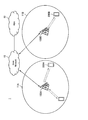
- FIG. 1 is a diagram showing an overall configuration of a communication system according to an embodiment of the present disclosure.
- the communication system 1 includes a plurality of base stations 100 (100A and 100B), a plurality of terminal devices 200 (200A and 200B), a core network 12 and a PDN (Packet Data Network) 13.
- PDN Packet Data Network
- the base station 100 is a communication device that operates the cell 11 and provides a wireless communication service to one or more terminal devices 200 located inside the cell 11.
- the cell 11 is operated according to an arbitrary wireless communication system such as LTE or NR.
- the base station 100 is connected to the core network 12.
- the core network 12 is connected to a packet data network (PDN) 13 via a gateway device (not shown).
- PDN packet data network
- the core network 12 may include MME (Mobility Management Entity), S-GW (Serving gateway), P-GW (PDN gateway), PCRF (Policy and Charging Rule Function), and HSS (Home Subscriber Server).
- MME Mobility Management Entity
- S-GW Serving gateway
- P-GW Packet Data Network gateway
- PCRF Policy and Charging Rule Function
- HSS Home Subscriber Server
- the MME is a control node that handles signals on the control plane, and manages the moving state of the terminal device.
- the S-GW is a control node that handles user plane signals, and is a gateway device that switches a user data transfer path.
- the P-GW is a control node that handles user plane signals and is a gateway device that serves as a connection point between the core network 12 and the PDN 13.
- the PCRF is a control node that controls policies such as QoS (Quality of Service) for bearers and accounting.
- the HSS is a control node that handles subscriber data and performs service control.
- the terminal device 200 is a communication device that wirelessly communicates with the base station 100 under the control of the base station 100.
- the terminal device 200 measures the downlink signal from the base station 100 and reports the measurement information indicating the measurement result to the base station 100.
- the base station 100 controls wireless communication with the terminal device 200 based on the reported measurement information (hereinafter, also referred to as measurement report).
- the terminal device 200 can transmit an uplink signal for measurement to the base station 100.
- the base station 100 measures the uplink signal from the terminal device 200 and controls the wireless communication with the terminal device 200 based on the measurement information.
- the measurement using the uplink signal does not require a report in the measurement using the downlink signal, and thus the measurement information can be obtained earlier. Therefore, for example, when the moving speed of the terminal device 200 is high, it is desirable to perform the measurement using the uplink signal.
- the base stations 100 can exchange information with each other by using the X2 interface. For example, the base station 100 transmits measurement information regarding the terminal device 200 for which handover is predicted to another adjacent base station 100. As a result, stable handover is realized and the stability of wireless communication of the terminal device 200 is ensured.
- a wireless communication service operated by another RAT such as Wi-Fi (registered trademark) or MultFire is provided around the communication system 1 other than the cellular communication.
- a communication device is typically connected to the PDN 13.
- the base station 100, the terminal device 200, and other communication devices operated by the RAT are also collectively referred to as nodes below.
- NR-U unlicensed
- LAA Licensed Assisted Access
- dual connectivity Dual Connectivity
- standalone Standand-alone
- ETSI BRAN defines two channel access methods, LBE (Load-based equipment) and FBE (Frame-based equipment).
- ⁇ LBE LBE is a channel access method (corresponding to the first method) in which carrier sensing is performed at an arbitrary timing.
- the carrier sense is a concept that includes LBT (Listen Before Talk), CSMA / CA (Carrier Sense Multiple Accesses with Collision Avoidance), and CCA (Channel Clear Assessment).
- LBE is a method adopted in Wi-Fi etc. to access a channel by the same operation as CSMA / CA.
- a node performing LBE performs CCA multiple times by random backoff, and transmission is possible when the channel is clear in all CCA slots.
- LTE LAA channel access is LBE
- NR-U is expected to introduce LBE-based channel access.
- introduction of FBE in addition to LBE is being studied.
- FBE FBE is a channel access method (corresponding to the second method) in which carrier sensing is performed at a predetermined timing.
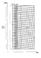
- FBE a frame is defined and CCA is performed in frame units. The outline of the FBE will be described below with reference to FIG.
- FIG. 2 is a diagram for explaining the outline of FBE.
- the upper part of FIG. 2 shows the timing of CCA with the horizontal axis as the time axis.
- the lower part of FIG. 2 shows the transmission timing with the horizontal axis as the time axis.
- a fixed frame period (Fixed Frame Period) is defined, and immediately before that, CCA is performed only once. If the channel is clear, transmission is possible, and if the channel is busy, transmission is awaited until the next fixed frame period. If the transmission is possible, the transmission is performed during the channel occupation time (Channel Occupancy Time) and is stopped during the idle period (Idle Period).
- the first difference between LBE and FBE is the number of CCA.
- LBE the number of CCA performed before transmission is one or more
- FBE the number of CCA performed before transmission is one.
- the second difference between LBE and FBE is the presence or absence of frame definition.
- the LBE does not define a fixed frame section for channel access, whereas the FBE defines a fixed frame section for channel access.
- the idle section defined in the fixed frame section is not defined, whereas in the FBE, the idle section is defined.
- a frame different from a frame for channel access such as a frame for synchronization or a scheduling unit (for example, a radio frame or a slot), can be defined for both.
- the third difference between LBE and FBE is the timing of CCA.
- FBE the timing of CCA is arbitrary, whereas in LBE, the timing is fixed immediately before the fixed frame section.
- the fourth difference between LBE and FBE is the presence or absence of a collision window (Contention Window).
- a collision window is set in order to perform one or more CCA, whereas in FBE, no collision window is set.
- the priority class (Priority Class) used for setting the collision window is set in the LBE, the priority class may not be set in the FBE.
- FIG. 3 is a diagram for explaining the technical problem of the present embodiment.
- the upper part of FIG. 3 shows a state of communication by the node X using FBE with the horizontal axis as the time axis.
- the lower part of FIG. 3 shows a state of communication by the node Y using FBE with the horizontal axis as the time axis.
- the node X and the node Y are not synchronized, the node X is always transmitting at the timing when the node Y performs CCA, and the node Y cannot transmit for a long time. ..
- An example where the node X and the node Y are not synchronized is a case where the node X and the node Y are operated by different operators or operated by different RATs. As shown in FIG. 3, even among a plurality of nodes that both use FBE, inequalities in transmission opportunities may occur.
- the timing of channel access is smaller in FBE than in LBE, so FBE can acquire excessive transmission opportunities as compared with LBE.
- the LBE may acquire the transmission opportunity excessively as compared with the FBE.
- the present disclosure proposes a mechanism capable of realizing fair channel access among a plurality of nodes.
- the proposed technique switches whether to use LBE or FBE as a channel access method between the base station 100 and the terminal device 200. Furthermore, the proposed technique flexibly sets the carrier sense in the channel access method used by the base station 100 and the terminal device 200.
- the proposed technology can realize the fair channel access by flexibly setting the channel access method and the carrier sense so as to suppress the unfairness of the transmission opportunity.
- ⁇ Channel access procedure for unlicensed channel A channel access (Channel access, Listen before Talk) procedure is performed in order to access an unlicensed channel transmitted by a base station apparatus or a terminal apparatus.
- sensing of the channel is performed once or multiple times. Based on the result of the sensing, it is determined whether the channel is idle (idle, unoccupied, available, enable) or busy (busy, occupied, unavailable, disable) (determination of vacancy). In channel sensing, the power of the channel at a given latency is sensed.
- LBE load-based equipment
- the waiting time of the channel access procedure there are a first waiting time (slot), a second waiting time, a third waiting time (deferral period), and a fourth waiting time.
- -A slot is a unit of waiting time of a base station device and a terminal device in a channel access procedure.
- the slot is defined by, for example, 9 microseconds.
- the second waiting time is defined as, for example, 16 microseconds.
- the defer period is composed of a second waiting time and a plurality of consecutive slots following the second waiting time.
- the number of consecutive slots following the second waiting time is determined based on the priority class (channel access priority class) used to satisfy the QoS.
- the fourth waiting time is composed of the second waiting time and one slot following it.
- the base station device or terminal device senses a predetermined channel during a predetermined slot.
- a given slot is considered idle if the power detected by the base station or terminal for at least 4 microseconds within the given slot period is less than a predetermined power detection threshold. .. On the other hand, if the power is greater than the predetermined power detection threshold, then the given slot is considered busy.
- the channel access procedure includes a first channel access procedure and a second channel access procedure.
- the first channel access procedure is performed using a plurality of slots and deferral periods.
- the second channel access procedure is performed with one fourth latency.
- the parameters relating to channel access include, for example, the minimum collision window, the maximum collision window, the maximum channel occupation time, the value that the collision window can take, and the like.
- the priority class is defined by the value of QCI (QoS class identifier) that processes QoS (Quality of Service).
- QCI QoS class identifier
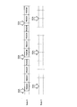
- Table 1 shows a correspondence table of parameters related to priority classes and channel access
- Table 2 shows an example of mapping of priority classes and QCIs.
- Channel sensing is performed during the (0) postponement period. If the channel was idle in the slot within the deferral period, go to step (1), else go to step (6).
- the initial value of the counter is an integer between 0 and the collision window CW.
- the initial value of the counter is randomly determined according to the uniform distribution.
- the initial value of the counter is set in the counter N, and the process proceeds to step (2).
- step (3) Waiting for additional slot period. Also, in that additional slot, the channel is sensed. If the additional slot was idle, go to step (4), else go to step (5).
- step (2) If the counter N is 0, stop this procedure. If not, proceed to step (2).
- step (6) Addition of postponement period and waiting.
- the channel is also sensed until it is detected as busy on any one of the slots included in the additional suspension period or until all slots included in the additional suspension period are detected to be idle. .. Then, the process proceeds to step (6).
- step (6) If the channel is sensed to be idle in all of the slots included in its additional deferral period, go to step (4), else go to step (5).
- step (4) in the above procedure After the step (4) in the above procedure is stopped, transmission including data such as PDSCH and PUSCH is performed on that channel.
- transmission may not be performed on that channel. In this case, then, the transmission may be performed without performing the above procedure if the channel was idle in all of the slots and deferrals immediately before the transmission. On the other hand, if the channel was not idle in any of its slots and its deferrals, then it was sensed that the channel was idle in all of the slots in the additional deferrals, then (1 ) Go to step.
- the transmission may occur immediately after the channel is considered idle as a result of sensing at least the fourth latency time. On the other hand, if the channel is not considered idle as a result of sensing at least the fourth latency, then no transmission occurs.
- ⁇ Collision window adaptation procedure The collision window CW (contention window) used in the first channel access procedure is determined based on the collision window adaptation procedure.
- the value of collision window CW is held for each priority class. Further, the collision window CW takes a value between the minimum collision window and the maximum collision window. The minimum collision window and the maximum collision window are determined based on the priority class.
- Adjustment of the collision window CW value is performed before the step (1) of the first channel access procedure. Increase the value of the collision window CW if the NACK rate is higher than the threshold in at least the HARQ response corresponding to the reference subframe in the collision window adaptation procedure or the shared channel of the reference HARQ process, otherwise, Set the value to the minimum collision window.
- the base station apparatus When performing downlink transmission including PDSCH, PDCCH, and / or EPDCCH in the unlicensed channel, the base station apparatus accesses the channel based on the first channel access procedure and performs the downlink transmission. ..
- the base station device when performing downlink transmission including DRS but not PDSCH, accesses the channel based on the second channel access procedure and performs the downlink transmission.
- the downlink transmission period is preferably shorter than 1 millisecond.
- ⁇ Details of uplink channel access procedure> In the unlicensed channel, when instructed to perform the first channel access procedure in the uplink grant that schedules the PUSCH, the terminal device performs the first channel access procedure before the uplink transmission including the PUSCH. ..
- the terminal device when instructed to perform the second channel access procedure in the uplink grant that schedules the PUSCH, performs the second channel access procedure before the uplink transmission including the PUSCH.
- the terminal device performs the second channel access procedure before the uplink transmission.
- the terminal device of the uplink transmission does not depend on the procedure type instructed by the uplink grant. Perform the second channel access procedure before.
- the terminal device performs the second channel access procedure before the uplink transmission.
- ⁇ NR channel access procedure in this embodiment> In the channel access procedure for an unlicensed channel using NR, non-beamformed channel sensing and beamformed channel sensing are performed.
- Channel sensing without beamforming is channel sensing by reception with uncontrolled directivity or channel sensing without direction information.
- the channel sensing having no direction information is, for example, channel sensing obtained by averaging the measurement results in all directions.
- the transmitting station does not have to recognize the directivity (angle, direction) used in channel sensing.
- Beam-formed channel sensing is channel sensing by receiving with controlled directivity or channel sensing with direction information. That is, it is channel sensing in which the reception beam is directed in a predetermined direction.
- a transmitting station having a function of performing beamformed channel sensing can perform channel sensing one or more times using different directivities.
- the transmitting station can reduce the frequency of detection of communication links that do not interfere, and reduce the exposed terminal problem.
- ⁇ Channel access for frame-based equipment FBE>
- a channel access (Listen before Talk) procedure defined as a frame-based equipment (FBE) one channel sensing (sensing) is performed before transmission. Based on the result of the sensing, it is determined whether the channel is idle (idle, unoccupied, available, enable) or busy (busy, occupied, unavailable, disable) (determination of vacancy).
- the power of the channel at a given latency is sensed.
- the transmission and / or reception configuration used in the frame-based device has a periodic timing called a fixed frame period (Fixed Frame Period).
- Fixed channel section is set in channel access of frame-based device.
- the fixed frame period is set between 1 ms and 10 ms.
- the fixed frame section can be changed only once in 200 milliseconds.
- the device performs channel sensing immediately before the start of transmission from the beginning of the fixed frame section.
- the device performs sensing once using one slot composed of 9 microseconds or less.
- a channel is considered to be busy if, as a result of sensing the channel, the power value is greater than a predetermined power detection threshold. On the other hand, if the power value is less than the predetermined power detection threshold, the channel is clear and the device can transmit.
- the device can transmit during the Channel Occupancy Time.
- the device can perform multiple transmissions without sensing if the gap between the multiple transmissions is 16 microseconds or less within the channel occupation time. On the other hand, if the gap between multiple transmissions exceeds 16 microseconds, the device needs to do additional channel sensing. Similarly, additional channel sensing is performed once using one slot.
- the channel exclusive time for channel access of frame-based devices does not exceed 95% of the fixed frame period.
- the idle period (Idle Period) in channel access of the frame-based device is 5% or more of the fixed frame period.
- the idle section is 100 microseconds or more.
- the response (ACK / NACK, HARQ-ACK) to the transmission from the device may be transmitted within the channel exclusive time.
- This preamble signal (initial signal, wake-up signal) can be generated for purposes of downlink detection, reduction of PDCCH monitoring, and coexistence / spatial reuse. Further, as shown in FIG. 4, this preamble signal is placed at the head of the signal transmitted from base station 100.
- the preamble signal may be transmitted from the base station 100 every symbol, or may be transmitted once every several symbols.
- the transmission cycle of the preamble signal may be associated with the PDCCH cycle or may be independent. In consideration of suppressing the power used by the terminal device 200, it is desirable that the transmission cycle of the preamble signal be independent of the PDCCH cycle.
- a plurality of preamble signals may be placed within a channel occupancy time (COT). When the preamble signal is placed in the COT, it may be placed at the beginning of the slot or in the middle of the slot. In either case, the preamble signal can be arranged in one slot cycle.
- COT channel occupancy time
- the preamble signal may be used for RRM / RLM / CSI measurement.
- the preamble signal can be set as one of RLM-RSs.
- the transmission power of the preamble signal is preferably fixed if it is used for RRM / RLM measurement.
- the transmission power of the preamble signal may be set in the terminal device in a higher (upper) layer.
- the power ratio between the DMRS of the PDCCH and the preamble signal may be set in the terminal device in a higher (upper) layer.
- the terminal device 200 When the terminal device 200 detects the preamble signal, the terminal device 200 starts monitoring the PDCCH of the minislot. Monitoring the PDCCH in the minislot means monitoring the PDCCH in the middle of the slot. This is a CORESET Configuration associated with a preamble signal that is different from the normal CORESET Configuration. When the terminal device 200 does not detect the preamble signal, the terminal device 200 monitors the slot-based PDCCH. This is a CORESET Configuration that is not tied to the activation signal.
- At least the DMRS of the preamble signal and the common PDCCH is pseudo collocation (QCL: Quasi Co-Location).
- the terminal device performs signal processing on the assumption that the preamble signal and the DMRS of the common PDCCH are QCL.
- the preamble signal may consist of one type of sequence and one symbol.
- FIG. 5 is an explanatory diagram showing a configuration example of a preamble signal.
- a sequence having a high orthogonal characteristic such as a ZC sequence or an m sequence, which can be separated even if collision occurs (even if the same resource is used).
- the preamble signal may consist of one type of sequence, 2 symbols or more.
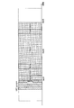
- FIG. 6 is an explanatory diagram showing a configuration example of the preamble signal. In this configuration, resources are assigned in an interlaced manner on the frequency axis. With this configuration, different frequency resources can be used between cells due to frequency reuse, and thus the detection rate can be improved. A sequence having a large number of orthogonal sequences such as a Gold sequence may be used for this preamble signal.
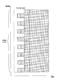
- the preamble signal may be composed of a combination of two types of sequences and two or more symbols.
- FIG. 7 is an explanatory diagram showing a configuration example of the preamble signal. It is preferable that the preamble signal is used in combination with a sequence having different characteristics such as a sequence having a high orthogonal characteristic such as a ZC sequence or an m sequence and a sequence having a large number of orthogonal sequences such as a Gold sequence. Since this configuration can use a plurality of sequences having different characteristics, it is possible to construct an appropriate signal sequence according to the application.
- a sequence with a low detection load for example, a ZC sequence
- a sequence with a low cross-correlation for example, an m sequence
- a sequence with a low cross-correlation for example, an m sequence
- frequency resources may be allocated in an interlaced manner to the configuration shown in FIG. 7.
- FIG. 8 is an explanatory diagram showing a configuration example of a preamble signal, and is an explanatory diagram showing a configuration in which frequency resources are allocated in an interlaced manner.
- FIG. 9 is an explanatory diagram showing a configuration example of the preamble signal, and is an explanatory diagram showing a configuration in which only one type of one symbol is assigned interlaced frequency resources.
- Preamble signal may have two or more kinds of sequences alternately arranged.
- FIG. 10 is an explanatory diagram showing a configuration example of a preamble signal, and is an explanatory diagram showing a configuration in which two types of sequences are alternately arranged. This configuration can transmit multiple types of sequences with one symbol.
- the preamble signal may have a configuration in which the first sequence is placed in the center of the carrier and the second sequence is multiplexed on the remaining frequencies.
- FIG. 11 is an explanatory diagram showing a configuration example of the preamble signal. With such a configuration, the first sequence facilitates synchronization with the carrier center frequency.
- FIG. 12 is an explanatory diagram showing a configuration example of the preamble signal.
- the preamble signal can be used as a discovery signal or a signal for initial access. Further, with such a configuration, it is possible to improve the transmission frequency of SS / PBCH blocks.
- the wireless LAN preamble may be used as the Preamble signal.
- the wireless LAN preamble may include STF (Short Training Field), LTF (Long Training Field), SIG (Signal Field), PHY header, and / or MAC header.
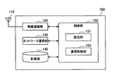
- FIG. 13 is a block diagram showing an example of the configuration of the base station 100 according to this embodiment.
- the base station 100 includes an antenna unit 110, a wireless communication unit 120, a network communication unit 130, a storage unit 140, and a control unit 150.
- Antenna unit 110 The antenna unit 110 radiates the signal output from the wireless communication unit 120 into space as a radio wave. Further, the antenna unit 110 converts a radio wave in the space into a signal and outputs the signal to the wireless communication unit 120.
- the wireless communication unit 120 transmits and receives signals. For example, the wireless communication unit 120 transmits a downlink signal to the terminal device and receives an uplink signal from the terminal device.
- the network communication unit 130 transmits and receives information.
- the network communication unit 130 transmits information to other nodes and receives information from other nodes.
- the other node includes another base station, another relay, another wireless LAN AP (Access Point) or wireless LAN STA (Station), and a core network node.
- Storage unit 140 The storage unit 140 temporarily or permanently stores a program and various data for the operation of the base station 100.
- Control unit 150 controls the overall operation of the base station 100 and provides various functions of the base station 100.
- the control unit 150 includes a setting unit 151 and a communication control unit 153.
- the setting unit 151 has a function of setting the communication between the terminal device 200 connected to the base station 100. For example, the setting unit 151 sets (that is, determines) the channel access method used by the base station 100 and the terminal device 200. Specifically, the setting unit 151 sets whether the base station 100 and the terminal device 200 use LBE or FBE. The setting unit 151 also sets (that is, determines) the carrier sense performed by the base station 100 and the terminal device 200. Then, the setting unit 151 notifies the terminal device 200 of the setting information indicating the setting of the channel access method and the carrier sense that the terminal device 200 should use.
- the setting unit 151 performs setting in the unlicensed band. That is, the setting unit 151 performs setting of the channel access method and carrier sense in the unlicensed band performed between the base station 100 and the terminal device 200, and notifies the terminal device 200 of the setting information.
- the communication control unit 153 has a function of controlling communication with the terminal device 200.
- the communication control unit 153 communicates with the terminal device 200 according to the setting of the channel access method by the setting unit 151.
- the base station 100 can use LBE and FBE, and the communication control unit 153 communicates with the terminal device 200 using either LBE or FBE. Further, the communication control unit 153 performs carrier sense according to the carrier sense setting made by the setting unit 151.
- the control unit 150 may further include other components other than these components. That is, the control unit 150 can perform operations other than the operations of these components.
- FIG. 14 is a block diagram showing an example of the configuration of the terminal device 200 according to this embodiment.
- the terminal device 200 includes an antenna unit 210, a wireless communication unit 220, a storage unit 230, and a control unit 240.
- the antenna unit 210 radiates the signal output by the wireless communication unit 220 into space as a radio wave.
- the antenna unit 210 also converts radio waves in space into a signal and outputs the signal to the wireless communication unit 220.
- the wireless communication unit 220 transmits and receives signals. For example, the wireless communication unit 220 receives a downlink signal from the base station and transmits an uplink signal to the base station.
- Storage unit 230 The storage unit 230 temporarily or permanently stores a program and various data for the operation of the terminal device 200.
- Control unit 240 controls the overall operation of the terminal device 200 and provides various functions of the terminal device 200.
- the control unit 240 includes a setting unit 241 and a communication control unit 243.
- the setting unit 241 has a function of making settings relating to communication between the base station 100 connected to the terminal device 200. For example, the setting unit 151 sets the channel access method to use based on the setting information notified from the base station 100. In addition, the setting unit 151 sets carrier sense based on the setting information notified from the base station 100. Here, the setting unit 241 performs setting in the unlicensed band. That is, the setting unit 241 performs the setting of the channel access method and the setting of the carrier sense in the unlicensed band performed between the base station 100 and the terminal device 200 based on the setting information.
- the communication control unit 243 has a function of controlling communication with the base station 100.
- the communication control unit 243 communicates with the base station 100 according to the setting made by the setting unit 241.
- the terminal device 200 can use LBE and FBE, and the communication control unit 243 communicates with the base station 100 using either LBE or FBE. Further, the communication control unit 243 performs carrier sense according to the carrier sense setting made by the setting unit 241.
- the control unit 240 may further include other components other than these components. That is, the control unit 240 can perform operations other than the operations of these components.
- the channel access method setting information includes information indicating the channel access method that the terminal device 200 should use.
- the setting information includes at least one of the information described below as information indicating the channel access method to be used.
- the setting information may include information indicating whether to use FBE. Further, the setting information may include information indicating whether to use LBE. Alternatively, the setting information may include information indicating the channel access method to be used.
- the setting information may include information indicating whether or not synchronization has been established between the base station 100 and another node.
- the other node is, for example, a base station adjacent to the base station 100.
- the terminal device 200 sets FBE as the channel access method to be used, and otherwise sets LBE. As a result, it becomes possible to switch the channel access method according to the synchronization information between the nodes, and it is possible to prevent the occurrence of the unfairness of the transmission opportunity between the plurality of nodes using the FBE described above with reference to FIG. it can.
- the setting information may include information in which a position is associated with a channel access method to be used when the terminal device 200 is located at the position.
- the terminal device 200 uses FBE in a predetermined area indicated by the setting information, and uses LBE outside the predetermined area.
- the position indicated by the setting information may be a geographical position, a building (floor, room), a cell, or a tracking area.
- the setting information includes information indicating that LBE should be used inside a certain building (factory, hospital) and that FBE should be used outside the building. As a result, the channel access method can be switched according to the position.
- Information indicating a position may be information indicating a geographical position or information indicating a relative position from a reference position.
- the unit of position may be a physical distance, or a wireless distance (Radio Distance) represented from the received power intensity due to the physical distance and the path loss having a correlation.
- the predetermined area may be an area represented by a geographical position, or may be an area in which long-term received power intensity received from the wireless device is equal to or lower than or equal to a predetermined threshold.
- the geographical location information may include latitude and longitude information. It should be noted that the geographical position information may include altitude information.
- the information on the relative position is, for example, information on a relative position, a relative distance, and / or a relative direction from a wireless device (mainly, a fixed node such as the base station 100), and information on the wireless device (identifier of the wireless device ( Cell ID), geographical information, etc.).
- a wireless device mainly, a fixed node such as the base station 100
- information on the wireless device identifier of the wireless device ( Cell ID), geographical information, etc.
- the setting information may include information in which a frequency band is associated with a channel access method to be used when the terminal device 200 uses the frequency band.
- the terminal device 200 uses FBE in a predetermined frequency band indicated by the setting information, and uses LBE in a frequency band other than the predetermined frequency band.
- the channel access method can be switched according to the frequency band.
- the predetermined frequency band is, for example, the 6 GHz band.
- FBE may be set in the 6 GHz band and LBE may be set in the 5 GHz band.
- the setting information may include information in which time is associated with a channel access method that the terminal device 200 should use at the time. For example, the terminal device 200 uses FBE in a predetermined section indicated by the setting information, and uses LBE in a time other than the predetermined section. As a result, it becomes possible to switch the channel access method according to time.
- the setting information may be information instructing a combination of the above settings.
- the setting information is information indicating whether or not synchronization has been established between the base station 100 and another node, and a position and a channel access method to be used when the terminal device 200 is located at the position. And information associated with and may be included at the same time.
- the terminal device 200 can apply FBE when synchronization is established between the base station 100 and another node and the terminal device 200 is located in a predetermined area.
- the setting information includes information indicating the setting of carrier access to be performed by the terminal device 200.
- the setting information may include information indicating the frame structure in FBE.
- the setting information includes the length and timing of the fixed frame section, the ratio of the channel occupation time and the idle section.
- the timing of the fixed frame section means the timing of the beginning of the fixed frame section.
- the boundary of the fixed frame section at least coincides with the symbol boundary of LTE or NR. Furthermore, it is desirable that the beginning of the fixed frame section coincides with the beginning of the LTE or NR slot, but there may be a deviation (Offset), and the deviation may be set in the terminal device 200.
- the setting information may be notified to the terminal device 200 using PBCH (Physical Broadcast Channel) or system information (for example, SIB (System Information Block) 1). Further, the setting information may be notified in the uplink RRC setting.
- PBCH Physical Broadcast Channel
- SIB System Information Block
- the setting information may be included in the information regarding handover and notified.
- the setting information is included in the Handover Command and notified to the terminal device 200.
- the setting information is included in the RRC setting information regarding handover and is notified to the terminal device 200.
- the channel access method is not changed between the handover source and the handover destination, and when the setting information is included, the channel access method is changed based on the setting information.
- the setting information may be included in a MAC CI, a grant (that is, a DCI (Downlink Control Information)), or a Preamble signal and notified to the terminal device 200.
- a MAC CI that is, a DCI (Downlink Control Information)
- a grant that is, a DCI (Downlink Control Information)
- a Preamble signal notified to the terminal device 200.
- the setting information is not included, the channel access method performed immediately before is performed, and when the setting information is included, the channel access method is performed based on the setting information.
- the notification method may be a combination of the above.
- the terminal device 200 when notified by fallback DCI (that is, DCI format 0_0 or DCI format 1_0) or DCI of the shared search space, the terminal device 200 follows the setting information of the RRC setting, and otherwise, the terminal device 200 sets the DCI.
- the terminal device 200 sets the DCI.
- the channel access method and carrier sense may be set based on long-term guarantee.
- Long-term guarantees may be given based on location.
- the base station 100 is set to use FBE at a position where long-term guarantee is obtained, and is set to use LBE at other positions. At this time, the base station 100 is fixed at that position and does not move.
- Long-term guarantees may be obtained based on frequency band.
- the base station 100 is set to use FBE in a frequency band for which long-term guarantee is obtained and set to use LBE in another frequency band.
- Long-term guarantees may be obtained based on time.
- the base station 100 is set to use the FBE at the time when the long-term guarantee is obtained and set to use the LBE at other times.
- the time when a long-term guarantee can be obtained is set as a cycle, for example.
- the base station 100 is configured to use the FBE if the database gives approval to use the FBE, and otherwise configures to use the LBE.
- the channel access scheme and the carrier sense may be set based on the geographical location.
- the setting unit 151 can set the channel access method used for communication between the base station 100 and the terminal device 200 based on the position of the base station 100. Further, the setting unit 151 can set the channel access method used for communication between the base station 100 and the terminal device 200 based on the position of the terminal device 200.
- the setting unit 151 sets to use the LBE when there is a node that uses the LBE around the base station 100 or the terminal device 200, and uses the FBE when there is no node that uses the LBE around.
- the setting unit 151 may set the channel access method to be used based on the information from the database to which the base station 100 is connected.
- a database manages position information, RATs, channel access methods, and the like of adjacent base stations of the base station 100, relay nodes, and other RAT (for example, wireless LAN such as Wi-Fi) nodes.
- the information from the database may include information indicating the channel access method to be used, or may include information that combines the position information of another node and the channel access method.
- the database manages the communication settings of the base station 100.
- the database can give permission to use the radio resource to the connecting base station 100.
- the database can control transmission power, available resources (frequency and time resources), inter-base station synchronization, etc. for the base station 100 to which the database is connected.
- the database can manage channel access. That is, the database can allow a given device to use exclusive resources that other devices cannot access.
- the database can process part of the SON (Self-Organized Network, Self-Optimization Network) mechanism.
- the database can control wireless resource sharing among multiple operators. That is, the database is connected to the base stations 100 of a plurality of operators and exchanges control information regarding radio resource sharing control.
- the wireless resource sharing control information between operators may include PLNM (Public Land Mobile Network), available wireless resources, and physical cell identifiers (PCI, Physical Cell Identity).
- the database may be included as part of the core network device or may be located outside the core network.
- the channel access scheme and carrier sense may be set based on other nodes that use FBE.
- the setting unit 151 uses the channel access method used for communication between the base station 100 and the terminal device 200 based on the detection result of the other node that uses LBE. Can be set. For example, the setting unit 151 sets to use LBE when another node that uses LBE is detected, and sets to use FBE when another node that uses LBE is not detected.
- the subject to be detected may be the base station 100 or the terminal device 200. As a result, it is possible to prevent the occurrence of unfairness in the transmission opportunity between the node that uses the FBE and the node that uses the LBE.
- LBE -Setting based on detection of signal transmitted from other node
- Other nodes using LBE are detected based on the signal transmitted from the other node.
- the presence of other nodes that use LBE may be detected by ED (Energy detection).
- the threshold of ED can be set arbitrarily.
- the presence of other nodes using LBE may be detected when it is determined that the channel is busy for more than a predetermined number of times.
- the setting unit 151 sets to use LBE.
- the setting unit 151 sets to use FBE.
- the signals transmitted from other nodes can be detected by measurement.
- the measurement may be performed by the base station 100 or may be performed by the terminal device 200 and reported to the base station 100.
- the measurement target may be an RSSI (Received Signal Strength Indicator).
- the setting unit 151 sets to use the FBE when the received power from another node measured by the base station 100 or reported from the terminal device 200 is lower than a predetermined value, and otherwise the LBE. Set to use.
- the measurement target may be a channel busy ratio.
- the channel busy rate is the ratio of the time when the received power exceeds a predetermined value in a predetermined period.
- the setting unit 151 sets to use the FBE when the channel busy rate is below a predetermined value (for example, 10%), and sets to use the LBE when it is not.
- Signals transmitted from other nodes can be detected by detection of packets.
- the packet detection may be performed by the base station 100 or the terminal device 200.
- the packet to be detected is, for example, a Wi-Fi beacon.
- the setting unit 151 sets to use LBE when a Wi-Fi beacon is detected, and sets to use FBE otherwise.
- the sensor information is information that can be obtained by an arbitrary sensor device such as a radar or an imaging device.
- the setting unit 151 sets the FBE when it is confirmed from the sensor information obtained by the sensor device installed in the base station 100 or the terminal device 200 that there is no other node that uses the LBE in the vicinity. Set to use.
- the detection of other nodes based on the sensor information may be performed by AI (artificial intelligence).
- the setting unit 151 can set a channel access method used for communication between the base station 100 and the terminal device 200 by a usage request / response-based procedure. For example, the setting unit 151 transmits an FBE use request to another node before transmitting predetermined data. The setting unit 151 sets to use the FBE for channel access performed within a predetermined period when the FBE use permission is responded from another node, and when the FBE use disapproval is responded from the other node. Or, set to use LBE when there is no response.
- the setting unit 151 can set carrier sense settings according to the detection results of other nodes that use LBE.
- the setting unit 151 sets the frame configuration in FBE according to the detection result of another node that uses LBE.
- the setting target may include the channel occupation time in the fixed frame period and the length of the idle period. In addition, the channel occupation time and the length of the idle section may be different between the downlink and the uplink.
- the setting target may include the length of the fixed frame section. In addition, the length of the fixed frame section may be different between the downlink and the uplink.
- the channel access method and the carrier sense may be set based on the packet to be transmitted.
- the setting unit 151 can set the channel access method used for communication between the base station 100 and the terminal device 200 for each packet.
- the packet here may be a packet transmitted by the base station 100 or a packet transmitted by the terminal device 200.
- the setting unit 151 may set the channel access method to be used based on the packet size. For example, the setting unit 151 sets to use FBE when the packet size is small, and sets to use LBE when the packet size is large. As a result, unnecessary long-term channel occupation can be avoided.
- the setting unit 151 may set the channel access method to be used based on the use case of the packet. For example, the setting unit 151 sets FBE to be used for packets related to factory automation. In other words, the setting unit 151 may set the channel access method used by the terminal device 200 based on the QoS (Quality of Service) of the packet. Whether or not the packet is related to factory automation can be determined by QoS. For example, the setting unit 151 sets to use FBE when the device is installed in the factory.
- QoS Quality of Service
- the setting unit 151 may set the channel access method used by the terminal device 200 based on whether the packet is periodic or aperiodic. For example, the setting unit 151 sets to use FBE for packets related to periodic control information such as SRS (Sounding Reference Signal), scheduling request, CSI report, and periodic traffic such as voice and streaming, and others.
- the LBE is set to be used for the packets related to the aperiodic traffic.
- the channel access method and carrier sense may be set based on the priority of the signal of another node.
- the setting unit 151 sets the channel access method used for communication between the base station 100 and the terminal device 200 based on the priority of the packet transmitted from another node. For example, the setting unit 151 sets to use LBE when a high priority packet is detected, and sets to use FBE otherwise. As a result, it is possible to prevent the transmission of a packet having a high priority by another node.
- the information indicating the priority of the packet can be notified to the surroundings by the node.
- the information indicating the priority of the packet can be notified to the surroundings using the preamble signal.
- the PDCCH may be used to notify surroundings of information indicating the priority of the packet.
- the channel access method and carrier sense may be set periodically.
- the setting unit 151 switches the channel access method used for communication between the base station 100 and the terminal device 200 at a predetermined cycle. For example, the setting unit 151 sets to use FBE in a predetermined section and sets to use LBE in another section. Periodically switches between LBE and FBE. This makes it possible to reduce the unfairness of the transmission opportunity with other nodes.
- the channel access method and carrier sense may be set based on the information carried by the preamble signal.
- the setting unit 151 sets the channel access method used for communication between the base station 100 and the terminal device 200 based on the preamble signal from another node.
- the setting section 151 sets to use the FBE, and if not, the setting section 151 sets to use the LBE.
- the preamble signal may include an identifier that distinguishes between the NR base station and the wireless LAN AP.
- the identifier may be assigned to the sequence of the sequence or may be represented by the carried bit string.
- an identifier that distinguishes an NR base station or a wireless LAN AP is an operator ID (eg PLMN). If the operator ID includes an ID that is not any operator, the setting unit 151 can recognize that the signal source is the wireless LAN AP. When the terminal device recognizes that the transmission source is the wireless LAN AP, the terminal device does not have to perform carrier sense in the channel occupation time and band acquired by the transmission source, and does not perform PDCCH monitoring or channel measurement. Good. When the terminal device recognizes that the transmission source is the wireless LAN AP, the terminal device may later report to the base station 100 that there is a wireless LAN AP in the vicinity.
- an operator ID eg PLMN
- An example of an identifier that distinguishes an NR base station or wireless LAN AP is BSS (Basic Service Set) Color. If the BSS Color includes information that does not belong to any BSS, the setting unit 151 can recognize that the signal source is an LTE, MultiFire, or NR base station.
- the wireless LAN node recognizes that the signal source is the base station, the wireless LAN node does not need to perform carrier sense in the channel-occupying time and band obtained by the source, and may not perform signal decoding.
- the wireless LAN node recognizes that the transmission source is the base station, it may report to the wireless RAN AP later that there is a base station nearby.
- the channel access method and the carrier sense may be set based on the RAT.
- the setting unit 151 sets the channel access method used for communication between the base station 100 and the terminal device 200 based on the RAT.
- the terminal device 200 sets the channel access method to be used based on the RAT of the connected base station.
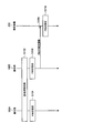
- FIG. 15 is a sequence diagram showing an example of the flow of communication control processing executed by the communication system 1 according to this embodiment. As shown in FIG. 15, the base station 100A, the base station 100B, and the terminal device 200 are involved in this sequence.
- the base station 100A and the base station 100B establish inter-base station synchronization (step S102).
- the base station 100A and the base station 100B set FBE as the channel access method used for communication with the terminal device 200 connected to each (steps S104 and 106).
- the base station 100B notifies the terminal device 200 connected to the base station 100B of the setting information including the fact that the FBE should be used and the setting of the carrier sense in the FBE (step S108).
- the terminal device 200 sets FBE as the channel access method used for communication with the base station 100B (step S110).
- the preamble signal may be used to notify the time when the channel is occupied (channel occupied time).
- the time notified by the preamble signal may be the maximum available time or the scheduled transmission time.
- the time when the Preamble signal notifies may be until the transmission timing of the next common PDCCH.
- the time reported by the preamble signal may be the time until the next uplink resource (eg, PRACH resource).
- the time notified by the preamble signal may be updated by later channel occupation time information.
- the preamble signal may be used to notify the band that occupies the channel (channel-proprietary band).
- the terminal device can recognize that the band in which the preamble signal is transmitted is exclusively used in that band.
- the information carried by the preamble signal can notify whether or not the channel is occupied in a band other than the band in which the preamble signal is transmitted.
- the band that occupies the channel can be notified even if different methods are used. For example, it is possible to notify whether or not the channel in the band designated by the common PDCCH is occupied.
- Common PDCCH is used to notify SFI (Slot Format Indicator).
- the common PDCCH is preferably sent in the first few symbols of the slot.
- the period for sending the common PDCCH is set by the RRC setting.
- the processing of PDCCH monitoring and measurement may be switched according to the band occupied by the channel. For example, in a band where the channel is not occupied, the terminal device does not monitor the PDCCH, does not buffer the PDSCH, and does not measure the channel. On the other hand, in the band in which the channel is occupied, the terminal device can monitor the PDCCH, buffer the PDSCH, and / or measure the channel.
- the base station 100 can broadcast the information (subCarrierSpacingCommon) designating the subcarrier interval of the PDSCH carrying the SIB1, the message 2 and the message 4 for the initial access, and the broadcast SI message and the PDCCH corresponding to the PDSCH on the PBCH.
- the terminal device recognizes that the PDSCH and PDCCH are sent at 60 kHz, and when the information indicating 30 kHz is sent, the PDSCH And recognize that the PDCCH is sent at 60 kHz.
- the base station 100 may be realized as an eNB (evolved Node B) of any type such as a macro eNB or a small eNB.
- a small eNB may be an eNB that covers a cell smaller than a macro cell, such as a pico eNB, a micro eNB or a home (femto) eNB.
- the base station 100 may be realized as another type of base station such as a NodeB or a BTS (Base Transceiver Station).
- the base station 100 may include a main body (also referred to as a base station device) that controls wireless communication, and one or more RRHs (Remote Radio Heads) arranged in a location different from the main body.
- RRHs Remote Radio Heads
- various types of terminals described below may operate as the base station 100 by temporarily or semi-permanently executing the base station function.
- the terminal device 200 is a smartphone, a tablet PC (Personal Computer), a notebook PC, a portable game terminal, a mobile terminal such as a portable / dongle type mobile router or a digital camera, or an in-vehicle terminal such as a car navigation device. May be realized as. Further, the terminal device 200 may be realized as a terminal that performs M2M (Machine To Machine) communication (also referred to as an MTC (Machine Type Communication) terminal). Further, the terminal device 200 may be a wireless communication module (for example, an integrated circuit module configured by one die) mounted on these terminals.
- M2M Machine To Machine
- MTC Machine Type Communication
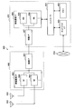
- FIG. 16 is a block diagram showing a first example of a schematic configuration of an eNB to which the technology according to the present disclosure can be applied.
- the eNB 800 has one or more antennas 810 and a base station device 820. Each antenna 810 and the base station device 820 can be connected to each other via an RF cable.
- Each of the antennas 810 has a single or a plurality of antenna elements (for example, a plurality of antenna elements forming a MIMO antenna), and is used for the base station device 820 to transmit and receive radio signals.
- the eNB 800 includes a plurality of antennas 810 as illustrated in FIG. 16, and the plurality of antennas 810 may correspond to a plurality of frequency bands used by the eNB 800, respectively. 16 illustrates an example in which the eNB 800 has a plurality of antennas 810, the eNB 800 may have a single antenna 810.
- the base station device 820 includes a controller 821, a memory 822, a network interface 823, and a wireless communication interface 825.
- the controller 821 may be, for example, a CPU or a DSP, and operates various functions of the upper layer of the base station device 820. For example, the controller 821 generates a data packet from the data in the signal processed by the wireless communication interface 825, and transfers the generated packet via the network interface 823. The controller 821 may generate a bundled packet by bundling data from a plurality of baseband processors and transfer the generated bundled packet. Further, the controller 821 is a logic that executes control such as radio resource control (Radio Resource Control), radio bearer control (Radio Bearer Control), mobility management (Mobility Management), inflow control (Admission Control) or scheduling (Scheduling). It may have a general function.
- Radio Resource Control Radio Resource Control
- Radio Bearer Control Radio Bearer Control
- Mobility Management Mobility Management
- Admission Control Inflow control
- scheduling scheduling
- the control may be executed in cooperation with a peripheral eNB or core network node.
- the memory 822 includes a RAM and a ROM, and stores a program executed by the controller 821 and various control data (for example, a terminal list, transmission power data, scheduling data, etc.).
- the network interface 823 is a communication interface for connecting the base station device 820 to the core network 824. Controller 821 may communicate with core network nodes or other eNBs via network interface 823. In that case, the eNB 800 and the core network node or another eNB may be connected to each other by a logical interface (for example, the S1 interface or the X2 interface).
- the network interface 823 may be a wired communication interface or a wireless communication interface for wireless backhaul. When the network interface 823 is a wireless communication interface, the network interface 823 may use a higher frequency band for wireless communication than the frequency band used by the wireless communication interface 825.
- the wireless communication interface 825 supports a cellular communication method such as LTE (Long Term Evolution) or LTE-Advanced, and provides a wireless connection to a terminal located in the cell of the eNB 800 via the antenna 810.
- the wireless communication interface 825 may typically include a baseband (BB) processor 826, an RF circuit 827, and the like.
- the BB processor 826 may perform, for example, encoding / decoding, modulation / demodulation, and multiplexing / demultiplexing, and each layer (eg, L1, MAC (Medium Access Control), RLC (Radio Link Control), and PDCP). (Packet Data Convergence Protocol)) various signal processing is executed.
- L1, MAC Medium Access Control
- RLC Radio Link Control
- PDCP Packet Data Convergence Protocol
- the BB processor 826 may have some or all of the logical functions described above instead of the controller 821.
- the BB processor 826 may be a module that includes a memory that stores a communication control program, a processor that executes the program, and a related circuit. The function of the BB processor 826 may be changed by updating the program. Good.
- the module may be a card or a blade inserted in the slot of the base station device 820, or a chip mounted on the card or the blade.
- the RF circuit 827 may include a mixer, a filter, an amplifier, and the like, and transmits and receives wireless signals via the antenna 810.
- the wireless communication interface 825 includes a plurality of BB processors 826 as shown in FIG. 16, and the plurality of BB processors 826 may respectively correspond to a plurality of frequency bands used by the eNB 800, for example.
- the wireless communication interface 825 may include a plurality of RF circuits 827 as shown in FIG. 16, and the plurality of RF circuits 827 may correspond to, for example, a plurality of antenna elements.
- 16 illustrates an example in which the wireless communication interface 825 includes a plurality of BB processors 826 and a plurality of RF circuits 827, the wireless communication interface 825 includes a single BB processor 826 or a single RF circuit 827. But it's okay.
- the eNB 800 illustrated in FIG. 16 one or more components (setting unit 151 and / or communication control unit 153) included in the control unit 150 described with reference to FIG. 13 are installed in the wireless communication interface 825. Good. Alternatively, at least some of these components may be implemented in controller 821. As an example, the eNB 800 includes a module including a part (for example, the BB processor 826) or all of the wireless communication interface 825 and / or the controller 821, and the one or more components may be mounted in the module. Good. In this case, the module stores a program for causing the processor to function as the one or more constituent elements (in other words, a program for causing the processor to execute the operation of the one or more constituent elements). You may run the program.
- the module stores a program for causing the processor to function as the one or more constituent elements (in other words, a program for causing the processor to execute the operation of the one or more constituent elements). You may run the program.
- a program for causing a processor to function as one or more components described above is installed in the eNB 800, and the wireless communication interface 825 (for example, the BB processor 826) and / or the controller 821 executes the program.
- the eNB 800, the base station device 820, or the module may be provided as an apparatus including the one or more constituent elements, and a program for causing a processor to function as the one or more constituent elements is provided. May be.
- a readable recording medium recording the above program may be provided.
- the wireless communication unit 120 described with reference to FIG. 13 may be mounted in the wireless communication interface 825 (for example, the RF circuit 827).
- the antenna unit 110 may be mounted on the antenna 810.
- the network communication unit 130 may be implemented in the controller 821 and / or the network interface 823.
- the storage unit 140 may be implemented in the memory 822.
- FIG. 17 is a block diagram showing a second example of a schematic configuration of an eNB to which the technology according to the present disclosure can be applied.
- the eNB 830 has one or more antennas 840, a base station device 850, and an RRH 860. Each antenna 840 and RRH 860 may be connected to each other via an RF cable. Also, the base station device 850 and the RRH 860 can be connected to each other by a high-speed line such as an optical fiber cable.
- Each of the antennas 840 has a single or a plurality of antenna elements (for example, a plurality of antenna elements forming a MIMO antenna), and is used for transmitting and receiving radio signals by the RRH 860.
- the eNB 830 may include a plurality of antennas 840 as illustrated in FIG. 17, and the plurality of antennas 840 may respectively correspond to a plurality of frequency bands used by the eNB 830, for example. Note that FIG. 17 shows an example in which the eNB 830 has a plurality of antennas 840, but the eNB 830 may have a single antenna 840.
- the base station device 850 includes a controller 851, a memory 852, a network interface 853, a wireless communication interface 855, and a connection interface 857.
- the controller 851, the memory 852, and the network interface 853 are the same as the controller 821, the memory 822, and the network interface 823 described with reference to FIG.
- the wireless communication interface 855 supports a cellular communication method such as LTE or LTE-Advanced, and provides a wireless connection to a terminal located in a sector corresponding to the RRH860 via the RRH860 and the antenna 840.
- the wireless communication interface 855 may typically include a BB processor 856 or the like.
- the BB processor 856 is the same as the BB processor 826 described with reference to FIG. 16 except that it is connected to the RF circuit 864 of the RRH 860 via the connection interface 857.
- the wireless communication interface 855 includes a plurality of BB processors 856 as shown in FIG. 17, and the plurality of BB processors 856 may correspond to a plurality of frequency bands used by the eNB 830, for example.
- FIG. 17 shows an example in which the wireless communication interface 855 includes a plurality of BB processors 856, the wireless communication interface 855 may include a single BB processor 856.
- connection interface 857 is an interface for connecting the base station device 850 (radio communication interface 855) to the RRH 860.
- the connection interface 857 may be a communication module for communication on the high-speed line connecting the base station device 850 (radio communication interface 855) and the RRH 860.
- the RRH 860 also includes a connection interface 861 and a wireless communication interface 863.
- connection interface 861 is an interface for connecting the RRH 860 (radio communication interface 863) to the base station device 850.
- the connection interface 861 may be a communication module for communication on the high speed line.
- the wireless communication interface 863 sends and receives wireless signals via the antenna 840.
- the wireless communication interface 863 may typically include an RF circuit 864 or the like.
- the RF circuit 864 may include a mixer, a filter, an amplifier, and the like, and transmits and receives a wireless signal through the antenna 840.
- the wireless communication interface 863 includes a plurality of RF circuits 864 as shown in FIG. 17, and the plurality of RF circuits 864 may correspond to, for example, a plurality of antenna elements. Note that FIG. 17 shows an example in which the wireless communication interface 863 includes a plurality of RF circuits 864, but the wireless communication interface 863 may include a single RF circuit 864.
- one or more components included in the control unit 150 described with reference to FIG. 13 are the wireless communication interface 855 and / or the wireless communication interface 855. It may be implemented in the communication interface 863. Alternatively, at least some of these components may be implemented in controller 851. As an example, the eNB 830 includes a module including a part (for example, the BB processor 856) or all of the wireless communication interface 855 and / or the controller 851, and the one or more components may be mounted in the module. Good.
- the module stores a program for causing the processor to function as the one or more constituent elements (in other words, a program for causing the processor to execute the operation of the one or more constituent elements). You may run the program.
- a program for causing the processor to function as one or more components described above is installed in the eNB 830, and the wireless communication interface 855 (for example, the BB processor 856) and / or the controller 851 executes the program.
- the eNB 830, the base station device 850, or the module may be provided as a device including the one or more components, and a program for causing a processor to function as the one or more components is provided. May be.
- a readable recording medium recording the above program may be provided.
- the wireless communication unit 120 described with reference to FIG. 13 may be implemented in the wireless communication interface 863 (for example, the RF circuit 864).
- the antenna unit 110 may be mounted on the antenna 840.
- the network communication unit 130 may be implemented in the controller 851 and / or the network interface 853.
- the storage unit 140 may be implemented in the memory 852.
- FIG. 18 is a block diagram showing an example of a schematic configuration of a smartphone 900 to which the technology according to the present disclosure can be applied.
- the smartphone 900 includes a processor 901, a memory 902, a storage 903, an external connection interface 904, a camera 906, a sensor 907, a microphone 908, an input device 909, a display device 910, a speaker 911, a wireless communication interface 912, and one or more antenna switches 915. It comprises one or more antennas 916, a bus 917, a battery 918 and an auxiliary controller 919.
- the processor 901 may be, for example, a CPU or a SoC (System on Chip), and controls the functions of the application layer and other layers of the smartphone 900.
- the memory 902 includes RAM and ROM and stores programs and data executed by the processor 901.
- the storage 903 may include a storage medium such as a semiconductor memory or a hard disk.
- the external connection interface 904 is an interface for connecting an external device such as a memory card or a USB (Universal Serial Bus) device to the smartphone 900.
- the camera 906 has an image sensor such as a CCD (Charge Coupled Device) or a CMOS (Complementary Metal Oxide Semiconductor), and generates a captured image.
- the sensor 907 may include a sensor group such as a positioning sensor, a gyro sensor, a geomagnetic sensor, and an acceleration sensor, for example.
- the microphone 908 converts a voice input to the smartphone 900 into a voice signal.
- the input device 909 includes, for example, a touch sensor that detects a touch on the screen of the display device 910, a keypad, a keyboard, a button or a switch, and receives an operation or information input from a user.
- the display device 910 has a screen such as a liquid crystal display (LCD) or an organic light emitting diode (OLED) display, and displays the output image of the smartphone 900.
- the speaker 911 converts the audio signal output from the smartphone 900 into audio.
- the wireless communication interface 912 supports a cellular communication system such as LTE or LTE-Advanced and executes wireless communication.
- the wireless communication interface 912 may typically include a BB processor 913, an RF circuit 914, and the like.
- the BB processor 913 may perform, for example, encoding / decoding, modulation / demodulation, multiplexing / demultiplexing, and the like, and performs various signal processing for wireless communication.
- the RF circuit 914 may include a mixer, a filter, an amplifier, and the like, and transmits and receives a wireless signal through the antenna 916.
- the wireless communication interface 912 may be a one-chip module in which the BB processor 913 and the RF circuit 914 are integrated.
- the wireless communication interface 912 may include a plurality of BB processors 913 and a plurality of RF circuits 914 as shown in FIG. Note that FIG. 18 illustrates an example in which the wireless communication interface 912 includes a plurality of BB processors 913 and a plurality of RF circuits 914, but the wireless communication interface 912 includes a single BB processor 913 or a single RF circuit 914. But it's okay.
- the wireless communication interface 912 may support other types of wireless communication systems such as a short-range wireless communication system, a close proximity wireless communication system or a wireless LAN (Local Area Network) system in addition to the cellular communication system, In that case, the BB processor 913 and the RF circuit 914 for each wireless communication system may be included.
- Each antenna switch 915 switches the connection destination of the antenna 916 among a plurality of circuits (for example, circuits for different wireless communication systems) included in the wireless communication interface 912.
- Each of the antennas 916 has a single or a plurality of antenna elements (for example, a plurality of antenna elements forming a MIMO antenna), and is used for transmitting and receiving radio signals by the radio communication interface 912.
- the smartphone 900 may have a plurality of antennas 916 as shown in FIG. 18 illustrates an example in which the smartphone 900 has a plurality of antennas 916, the smartphone 900 may have a single antenna 916.
- the smartphone 900 may include an antenna 916 for each wireless communication system.
- the antenna switch 915 may be omitted from the configuration of the smartphone 900.
- the bus 917 connects the processor 901, the memory 902, the storage 903, the external connection interface 904, the camera 906, the sensor 907, the microphone 908, the input device 909, the display device 910, the speaker 911, the wireless communication interface 912, and the auxiliary controller 919 to each other. ..
- the battery 918 supplies power to each block of the smartphone 900 shown in FIG. 18 via a power supply line partially shown by a broken line in the figure.
- the auxiliary controller 919 operates the minimum necessary functions of the smartphone 900 in the sleep mode, for example.
- one or more components included in the control unit 240 described with reference to FIG. 14 are implemented in the wireless communication interface 912. May be. Alternatively, at least some of these components may be implemented in processor 901 or auxiliary controller 919. As an example, the smartphone 900 includes a module including a part (eg, the BB processor 913) or all of the wireless communication interface 912, the processor 901, and / or the auxiliary controller 919, and the one or more constituent elements in the module. May be implemented.
- the module stores a program for causing the processor to function as the one or more constituent elements (in other words, a program for causing the processor to execute the operation of the one or more constituent elements). You may run the program.
- a program for causing a processor to function as one or more components described above is installed in the smartphone 900, and the wireless communication interface 912 (for example, the BB processor 913), the processor 901, and / or the auxiliary controller 919 are included. You may run the program.
- the smartphone 900 or the module may be provided as an apparatus including the one or more components, and a program for causing the processor to function as the one or more components may be provided.
- a readable recording medium recording the above program may be provided.
- the wireless communication unit 220 described with reference to FIG. 14 may be implemented in the wireless communication interface 912 (for example, the RF circuit 914).
- the antenna unit 210 may be mounted on the antenna 916.
- the storage unit 230 may be implemented in the memory 902.
- FIG. 19 is a block diagram showing an example of a schematic configuration of a car navigation device 920 to which the technology according to the present disclosure can be applied.
- the car navigation device 920 includes a processor 921, a memory 922, a GPS (Global Positioning System) module 924, a sensor 925, a data interface 926, a content player 927, a storage medium interface 928, an input device 929, a display device 930, a speaker 931 and wireless communication.
- An interface 933, one or more antenna switches 936, one or more antennas 937 and a battery 938 are provided.
- the processor 921 may be, for example, a CPU or a SoC, and controls the navigation function and other functions of the car navigation device 920.
- the memory 922 includes RAM and ROM and stores programs and data executed by the processor 921.
- the GPS module 924 measures the position (for example, latitude, longitude, and altitude) of the car navigation device 920 using GPS signals received from GPS satellites.
- the sensor 925 may include a sensor group such as a gyro sensor, a geomagnetic sensor, and a barometric pressure sensor, for example.
- the data interface 926 is connected to the vehicle-mounted network 941 via, for example, a terminal (not shown) and acquires data generated on the vehicle side such as vehicle speed data.
- the content player 927 plays back the content stored in the storage medium (eg, CD or DVD) inserted in the storage medium interface 928.
- the input device 929 includes, for example, a touch sensor that detects a touch on the screen of the display device 930, a button or a switch, and receives an operation or information input from the user.
- the display device 930 has a screen such as an LCD or an OLED display, and displays a navigation function or an image of reproduced content.
- the speaker 931 outputs the navigation function or the sound of the reproduced content.
- the wireless communication interface 933 supports a cellular communication system such as LTE or LTE-Advanced and executes wireless communication.
- the wireless communication interface 933 may typically include a BB processor 934, an RF circuit 935, and the like.
- the BB processor 934 may perform, for example, encoding / decoding, modulation / demodulation, multiplexing / demultiplexing, and the like, and perform various signal processing for wireless communication.
- the RF circuit 935 may include a mixer, a filter, an amplifier, and the like, and transmits and receives a wireless signal through the antenna 937.
- the wireless communication interface 933 may be a one-chip module in which the BB processor 934 and the RF circuit 935 are integrated.
- the wireless communication interface 933 may include a plurality of BB processors 934 and a plurality of RF circuits 935, as shown in FIG. Note that FIG. 19 illustrates an example in which the wireless communication interface 933 includes a plurality of BB processors 934 and a plurality of RF circuits 935, but the wireless communication interface 933 includes a single BB processor 934 or a single RF circuit 935. But it's okay.
- the wireless communication interface 933 may support other types of wireless communication systems such as a short-range wireless communication system, a close proximity wireless communication system, and a wireless LAN system in addition to the cellular communication system.
- a BB processor 934 and an RF circuit 935 for each communication method may be included.
- Each of the antenna switches 936 switches the connection destination of the antenna 937 between a plurality of circuits (for example, circuits for different wireless communication systems) included in the wireless communication interface 933.
- Each of the antennas 937 has a single or a plurality of antenna elements (for example, a plurality of antenna elements forming a MIMO antenna), and is used for transmitting and receiving radio signals by the radio communication interface 933.
- the car navigation device 920 may have a plurality of antennas 937 as shown in FIG. 19 illustrates an example in which the car navigation device 920 has a plurality of antennas 937, the car navigation device 920 may have a single antenna 937.
- the car navigation device 920 may include an antenna 937 for each wireless communication system.
- the antenna switch 936 may be omitted from the configuration of the car navigation device 920.
- the battery 938 supplies electric power to each block of the car navigation device 920 shown in FIG. 19 via a power supply line partially shown by a broken line in the figure. Further, the battery 938 stores electric power supplied from the vehicle side.
- the car navigation device 920 includes a module including a part (for example, the BB processor 934) or all of the wireless communication interface 933 and / or the processor 921, and the one or more components described above are mounted in the module. May be.
- the module stores a program for causing the processor to function as the one or more constituent elements (in other words, a program for causing the processor to execute the operation of the one or more constituent elements). You may run the program.
- a program for causing the processor to function as the one or more components is installed in the car navigation device 920, and the wireless communication interface 933 (eg, BB processor 934) and / or the processor 921 executes the program.
- the car navigation device 920 or the module may be provided as a device including the one or more constituent elements, and the program for causing the processor to function as the one or more constituent elements may be provided.
- a readable recording medium recording the above program may be provided.
- the wireless communication unit 220 described with reference to FIG. 14 may be implemented in the wireless communication interface 933 (for example, the RF circuit 935).
- the antenna unit 210 may be mounted on the antenna 937.
- the storage unit 230 may be implemented in the memory 922.
- the technology according to the present disclosure may be implemented as an in-vehicle system (or vehicle) 940 including one or more blocks of the car navigation device 920 described above, an in-vehicle network 941, and a vehicle-side module 942.
- vehicle-side module 942 generates vehicle-side data such as vehicle speed, engine speed, or failure information, and outputs the generated data to the vehicle-mounted network 941.
- the terminal device 200 can use, as the channel access method, the first method for performing carrier sense at an arbitrary timing and the second method for performing carrier sense at a predetermined timing. Is.
- the base station 100 notifies the terminal device 200 of the channel access method and carrier sense setting information to be used.
- the terminal device 200 sets the channel access method to be used based on the setting information notified from the base station 100, and sets the carrier sense.
- it is possible to flexibly set the channel access method and the carrier sense it is possible to suppress or reduce the occurrence of unfair transmission opportunities between nodes and realize fair channel access. Is possible.
- the first method for carrying out carrier sensing at an arbitrary timing and the second method for carrying out carrier sensing at a predetermined timing can be used in a terminal device, and the setting of the channel access method and carrier sensing to be used
- the setting information includes information indicating whether to use the second scheme.
- the setting information includes information indicating whether or not synchronization has been established between the base station and another node.
- the setting information includes information in which a position and a channel access method to be used when the terminal device is located at the position are associated with each other.
- the setting information includes information in which a frequency band and a channel access method to be used when the terminal device uses the frequency band are associated with each other, according to any one of (1) to (4) above.
- Base station. (6) The base station according to any one of (1) to (5), wherein the setting information includes information in which time is associated with a channel access method to be used by the terminal device at the time.
- the setting information includes information indicating a frame configuration in the second method.
- the control unit sets the frame configuration in the second method according to a detection result of another node using the first method, according to any one of (1) to (11) above.
- Base station. (13) The control unit sets a channel access method used for communication with the terminal device based on a priority of a packet transmitted from another node, any one of (1) to (12) above.
- the base station according to item. (14) The base station according to any one of (1) to (13), wherein the control unit switches a channel access method used for communication with the terminal device at a predetermined cycle.
- the first method is LBE (Load-based equipment)
- the second method is FBE (Frame-based equipment).
- a terminal device capable of using, as a channel access method, a first method for performing carrier sensing at an arbitrary timing and a second method for performing carrier sensing at a predetermined timing
- a terminal device comprising: a control unit for setting a channel access method to be used and setting carrier sense based on setting information of a channel access method and a carrier sense to be used notified from a base station.
- the first method for carrying out carrier sensing at an arbitrary timing and the second method for carrying out carrier sensing at a predetermined timing can be used in a terminal device, and the setting of the channel access method and carrier sensing to be used Signaling information, the method being performed by a processor.
- the first method for carrying out carrier sensing at an arbitrary timing and the second method for carrying out carrier sensing at a predetermined timing can be used in a terminal device, and the setting of the channel access method and carrier sensing to be used A recording medium in which a program for functioning as a control unit that notifies information is recorded.
- a channel access method a computer that controls a terminal device that can use a first method for performing carrier sensing at an arbitrary timing and a second method for performing carrier sensing at a predetermined timing, Based on the channel access method to be used and carrier sense setting information notified from the base station, a program for causing the channel access method to be used and a control unit for performing carrier sense setting is recorded. Recording medium.
- Communication System 11 Cell 12 Core Network 13 PDN 100 base station 110 antenna section 120 wireless communication section 130 network communication section 140 storage section 150 control section 151 setting section 153 communication control section 200 terminal device 210 antenna section 220 wireless communication section 230 storage section 240 control section 241 setting section 243 communication control section
Landscapes
- Engineering & Computer Science (AREA)
- Computer Networks & Wireless Communication (AREA)
- Signal Processing (AREA)
- Computer Security & Cryptography (AREA)
- Quality & Reliability (AREA)
- Mobile Radio Communication Systems (AREA)
Abstract
複数のノード間で公平なチャネルアクセスを実現することが可能な仕組みを提案する。チャネルアクセス方式として、任意のタイミングでキャリアセンスを行う第1の方式、及び所定のタイミングでキャリアセンスを行う第2の方式を使用可能な端末装置に、使用すべきチャネルアクセス方式及びキャリアセンスの設定情報を通知する制御部(150)、を備える基地局。
Description
本開示は、基地局、端末装置、方法及び記録媒体に関する。
セルラー移動通信の無線アクセス方式及び無線ネットワーク(以下、「Long Term Evolution(LTE)」、「LTE-Advanced(LTE-A)」、「LTE-Advanced Pro(LTE-A Pro)」、「New Radio(NR)」、「New Radio Access Technology(NRAT)」、「5G」、「Evolved Universal Terrestrial Radio Access(EUTRA)」、または「Further EUTRA(FEUTRA)」とも称する。)が、第三世代パートナーシッププロジェクト(3rd Generation Partnership Project: 3GPP)において検討されている。なお、以下の説明において、LTEは、LTE-A、LTE-A Pro、及びEUTRAを含み、NRは、NRAT、及びFEUTRAを含む。LTEでは基地局装置(基地局)はeNodeB(evolved NodeB)、NRでは基地局装置(基地局)はgNodeB、LTE及びNRでは端末装置(移動局、移動局装置、端末)はUE(User Equipment)とも称する。LTE及びNRは、基地局装置がカバーするエリアをセル状に複数配置するセルラー通信システムである。単一の基地局装置は複数のセルを管理してもよい。
NRは、LTEに対する次世代の無線アクセス方式として、LTEとは異なるRAT(Radio Access Technology)である。NRは、eMBB(Enhanced mobile broadband)、mMTC(Massive machine type communications)及びURLLC(Ultra reliable and low latency communications)を含む様々なユースケースに対応できるアクセス技術である。NRは、それらのユースケースにおける利用シナリオ、要求条件、及び配置シナリオなどに対応する技術フレームワークを目指して検討される。
アンライセンスバンド(unlicensed band、免許不要帯域)及びライセンス共有帯域(license shared band)において、セルラー通信を基とした無線アクセス方式の運用が検討されている。そのような免許不要帯域において他のノードや無線システムとの共存が重要とされており、LTE及びNRなどの無線アクセス方式に対して、送信する前にチャネルのセンシングを行うLBT(Listen Before Talk)や断続的送信(discontinuous transmission)などの機能が要求されている。アンライセンスバンドにおけるNRを基にした無線アクセス方式の詳細は、非特許文献1に開示されている。なお、アンライセンスバンドは、例えば、2.4GHz帯、5GHz帯、及び6GHz帯である。ライセンス共有バンドは、例えば、3.5GHz帯や37GHz帯である。
RP-172021, "Study on NR-based Access to Unlicensed Spectrum," 3GPP TSG RAN Meeting #77, Sapporo, Japan, September 11 - 14, 2017.
アンライセンスバンドにおいては、共存する種々のノード間で公平なチャネルアクセスを保つことが困難な場合がある。一例として、キャリアセンスに関する設定が異なるノード間では、公平なチャネルアクセスを保つことが困難な場合がある。
そこで、本開示では、複数のノード間で公平なチャネルアクセスを実現することが可能な仕組みを提案する。
本開示によれば、チャネルアクセス方式として、任意のタイミングでキャリアセンスを行う第1の方式、及び所定のタイミングでキャリアセンスを行う第2の方式を使用可能な端末装置に、使用すべきチャネルアクセス方式及びキャリアセンスの設定情報を通知する制御部、を備える基地局が提供される。
また、本開示によれば、チャネルアクセス方式として、任意のタイミングでキャリアセンスを行う第1の方式、及び所定のタイミングでキャリアセンスを行う第2の方式を使用可能な端末装置であって、基地局から通知された、使用すべきチャネルアクセス方式及びキャリアセンスの設定情報に基づいて、使用するチャネルアクセス方式を設定し、キャリアセンスの設定を行う制御部、を備える端末装置が提供される。
また、本開示によれば、チャネルアクセス方式として、任意のタイミングでキャリアセンスを行う第1の方式、及び所定のタイミングでキャリアセンスを行う第2の方式を使用可能な端末装置に、使用すべきチャネルアクセス方式及びキャリアセンスの設定情報を通知すること、を含む、プロセッサにより実行される方法が提供される。
また、本開示によれば、チャネルアクセス方式として、任意のタイミングでキャリアセンスを行う第1の方式、及び所定のタイミングでキャリアセンスを行う第2の方式を使用可能な端末装置により実行される方法であって、基地局から通知された、使用すべきチャネルアクセス方式及びキャリアセンスの設定情報に基づいて、使用するチャネルアクセス方式を設定し、キャリアセンスの設定を行うこと、を含む方法が提供される。
また、本開示によれば、コンピュータを、チャネルアクセス方式として、任意のタイミングでキャリアセンスを行う第1の方式、及び所定のタイミングでキャリアセンスを行う第2の方式を使用可能な端末装置に、使用すべきチャネルアクセス方式及びキャリアセンスの設定情報を通知する制御部、として機能させるためのプログラムが記録された記録媒体が提供される。
また、本開示によれば、チャネルアクセス方式として、任意のタイミングでキャリアセンスを行う第1の方式、及び所定のタイミングでキャリアセンスを行う第2の方式を使用可能な端末装置を制御するコンピュータを、基地局から通知された、使用すべきチャネルアクセス方式及びキャリアセンスの設定情報に基づいて、使用するチャネルアクセス方式を設定し、キャリアセンスの設定を行う制御部、として機能させるためのプログラムが記録された記録媒体が提供される。
以下に添付図面を参照しながら、本開示の好適な実施の形態について詳細に説明する。なお、本明細書及び図面において、実質的に同一の機能構成を有する構成要素については、同一の符号を付することにより重複説明を省略する。
また、本明細書及び図面において、実質的に同一の機能構成を有する要素を、同一の符号の後に異なるアルファベットを付して区別する場合もある。例えば、実質的に同一の機能構成を有する複数の要素を、必要に応じて基地局100A及び100Bのように区別する。ただし、実質的に同一の機能構成を有する複数の要素の各々を特に区別する必要がない場合、同一符号のみを付する。例えば、基地局100A及び100Bを特に区別する必要が無い場合には、単に基地局100と称する。
なお、説明は以下の順序で行うものとする。
1.はじめに
2.各装置の構成例
3.技術的特徴
4.応用例
5.まとめ
1.はじめに
2.各装置の構成例
3.技術的特徴
4.応用例
5.まとめ
<<1.はじめに>>
<1.1.システム構成例>
図1は、本開示の一実施形態に係る通信システムの全体構成を示す図である。図1に示したように、通信システム1は、複数の基地局100(100A及び100B)、複数の端末装置200(200A及び200B)、コアネットワーク12及びPDN(Packet Data Network)13を含む。
<1.1.システム構成例>
図1は、本開示の一実施形態に係る通信システムの全体構成を示す図である。図1に示したように、通信システム1は、複数の基地局100(100A及び100B)、複数の端末装置200(200A及び200B)、コアネットワーク12及びPDN(Packet Data Network)13を含む。
基地局100は、セル11を運用し、セル11の内部に位置する1つ以上の端末装置200へ無線通信サービスを提供する通信装置である。セル11は、例えばLTE又はNR等の任意の無線通信方式に従って運用される。基地局100は、コアネットワーク12に接続される。コアネットワーク12は、ゲートウェイ装置(図示せず)を介してパケットデータネットワーク(PDN)13に接続される。
コアネットワーク12は、MME(Mobility Management Entity)、S-GW(Serving gateway)、P-GW(PDN gateway)、PCRF(Policy and Charging Rule Function)及びHSS(Home Subscriber Server)を含み得る。若しくは、コアネットワーク12は、これらと同様の機能を有するNRのエンティティを含み得る。MMEは、制御プレーンの信号を取り扱う制御ノードであり、端末装置の移動状態を管理する。S-GWは、ユーザプレーンの信号を取り扱う制御ノードであり、ユーザデータの転送経路を切り替えるゲートウェイ装置である。P-GWは、ユーザプレーンの信号を取り扱う制御ノードであり、コアネットワーク12とPDN13との接続点となるゲートウェイ装置である。PCRFは、ベアラに対するQoS(Quality of Service)等のポリシー及び課金に関する制御を行う制御ノードである。HSSは、加入者データを取り扱い、サービス制御を行う制御ノードである。
端末装置200は、基地局100による制御に基づいて基地局100と無線通信する通信装置である。例えば、端末装置200は、基地局100からの下りリンク信号を測定して、測定結果を示す測定情報を基地局100へ報告する。基地局100は、報告された測定情報(以下、測定報告とも称される場合がある)に基づいて端末装置200との無線通信を制御する。他方、端末装置200は、測定のための上りリンク信号を基地局100に送信し得る。その場合、基地局100は、端末装置200からの上りリンク信号を測定して、測定情報に基づいて端末装置200との無線通信を制御する。上りリンク信号を用いた測定は、下りリンク信号を用いて測定における報告が不要なので、測定情報をより早く得ることが可能である。そのため、例えば端末装置200の移動速度が速い場合には、上りリンク信号を用いた測定が行われることが望ましい。
基地局100同士は、X2インタフェースを用いて、互いに情報を送受信することができる。例えば、基地局100は、ハンドオーバが予測される端末装置200に関する測定情報を、隣接する他の基地局100に送信する。これにより、安定的なハンドオーバが実現され、端末装置200の無線通信の安定性が確保される。
なお、図1には図示していないが、通信システム1の周囲には、セルラー通信以外の、例えばWi-Fi(登録商標)やMulteFire等の他のRATにより運用される無線通信サービスを提供する通信装置が存在し得る。かかる通信装置は、典型的には、PDN13に接続される。なお、基地局100及び端末装置200、並びに他のRATによる運用される通信装置を、以下ではノードとも総称する。
<1.2.キャリアアクセスの方式>
NR-U(unlicensed)は、キャリアアグリゲーションの仕組みを用いたLAA(Licensed Assisted Access)以外にも、様々なユースケースをサポートすることが想定されている。そのユースケースの一例として、デュアルコネクティビティ(Dual Connectivity)、及びアンライセンスバンドのみで運用されるスタンドアロン(Stand-alone)が挙げられる。また、そのユースケースの一例として、DLキャリア(下りリンク)及びUL(上りリンク)キャリアのどちらか一方がライセンスバンドで運用され、他方がアンライセンスバンドで運用されることも挙げられる。その場合、例えば、DLキャリアがライセンスバンドで運用されULキャリアがアンライセンスバンドで運用される。
NR-U(unlicensed)は、キャリアアグリゲーションの仕組みを用いたLAA(Licensed Assisted Access)以外にも、様々なユースケースをサポートすることが想定されている。そのユースケースの一例として、デュアルコネクティビティ(Dual Connectivity)、及びアンライセンスバンドのみで運用されるスタンドアロン(Stand-alone)が挙げられる。また、そのユースケースの一例として、DLキャリア(下りリンク)及びUL(上りリンク)キャリアのどちらか一方がライセンスバンドで運用され、他方がアンライセンスバンドで運用されることも挙げられる。その場合、例えば、DLキャリアがライセンスバンドで運用されULキャリアがアンライセンスバンドで運用される。
NR-Uに関し、ETSI BRANでは、LBE(Load-based equipment)及びFBE(Frame-based equipment)の2つのチャネルアクセス方式が規定されている。
・LBE
LBEとは、任意のタイミングでキャリアセンスを行うチャネルアクセス方式(第1の方式に相当)である。なお、キャリアセンスとは、LBT(Listen Before Talk)、CSMA/CA(Carrier Sense Multiple Accesses with Collision Avoidance)、及びCCA(Channel Clear Assessment)を包含する概念である。
LBEとは、任意のタイミングでキャリアセンスを行うチャネルアクセス方式(第1の方式に相当)である。なお、キャリアセンスとは、LBT(Listen Before Talk)、CSMA/CA(Carrier Sense Multiple Accesses with Collision Avoidance)、及びCCA(Channel Clear Assessment)を包含する概念である。
LBEは、Wi-Fi等に採用されている、CSMA/CAと同様の動作でチャネルにアクセスする方式である。LBEを行うノードは、ランダムバックオフによって複数回CCAを行い、全てのCCAスロットにおいてチャネルがクリアであった場合に送信可能となる。
LTE LAAのチャネルアクセスはLBEであり、NR-UにもLBEベースのチャネルアクセスが導入される見込みである。他方、NR-Uにおいて、LBEに加えて、FBEの導入が検討されている。
・FBE
FBEとは、所定のタイミングでキャリアセンスを行うチャネルアクセス方式(第2の方式に相当)である。FBEでは、フレームが定義されて、フレーム単位でCCAが行われる。以下、図2を参照しながらFBEの概要を説明する。
FBEとは、所定のタイミングでキャリアセンスを行うチャネルアクセス方式(第2の方式に相当)である。FBEでは、フレームが定義されて、フレーム単位でCCAが行われる。以下、図2を参照しながらFBEの概要を説明する。
図2は、FBEの概要を説明するための図である。図2の上段は、横軸を時間軸としたCCAのタイミングを示している。図2の下段は、横軸を時間軸とした送信のタイミングを示している。図2に示すように、FBEでは、固定フレーム区間(Fixed Frame Period)が定義され、その直前に1度だけCCAが実施される。チャネルがクリアであった場合には送信可能であり、チャネルがビジーであった場合には次の固定フレーム区間まで送信が待機される。送信可能であった場合、チャネル専有時間(Channel Occupancy Time)において送信が行われ、アイドル区間(Idle Period)において送信が停止される。
FBEにおけるCCAの回数は、1度の送信あたり1回である。そのため、チャネルアクセスの遅延を低減することができる。また、固定フレーム区間を短く設定することで、FBEを低遅延通信のユースケースに適用することができる。
・LBEとFBEとの相違点
LBEとFBEとの第1の相違点は、CCAの回数である。LBEでは送信前に行われるCCAの回数が1回以上であるのに対し、FBEでは送信前に行われるCCAの回数は1回である。
LBEとFBEとの第1の相違点は、CCAの回数である。LBEでは送信前に行われるCCAの回数が1回以上であるのに対し、FBEでは送信前に行われるCCAの回数は1回である。
LBEとFBEとの第2の相違点は、フレーム定義の有無である。LBEではチャネルアクセスのための固定フレーム区間が定義されていないのに対し、FBEではチャネルアクセスのための固定フレーム区間が定義される。更には、LBEでは固定フレーム区間内に定義されるアイドル区間が定義されていないのに対し、FBEではアイドル区間が定義される。なお、同期やスケジューリング単位のためのフレーム(例えば、無線フレーム、スロット)など、チャネルアクセスのためのフレームとは異なるフレームは、どちらにも定義されることができる。
LBEとFBEとの第3の相違点は、CCAのタイミングである。FBEではCCAのタイミングが任意であるのに対し、LBEでは固定フレーム区間の直前のタイミングに固定されている。
LBEとFBEとの第4の相違点は、衝突窓(Contention Window)の有無である。LBEでは1回以上のCCAを行うために衝突窓が設定されるのに対し、FBEでは衝突窓が設定されない。更に、LBEには衝突窓の設定に用いられる優先クラス(Priority Class)が設定されるのに対し、FBEでは優先クラスが設定されなくてもよい。
<1.3.技術的課題>
図3は、本実施形態の技術的課題を説明するための図である。図3の上段は、横軸を時間軸とした、FBEを使用するノードXによる通信の様子を示している。図3の下段は、横軸を時間軸とした、FBEを使用するノードYによる通信の様子を示している。図3に示した例では、ノードXとノードYとの間では、同期がとれていないので、ノードYがCCAを行うタイミングでは常にノードXが送信を行っており、ノードYは長期間送信できない。ノードXとノードYとの同期がとれていない例としては、ノードX及びノードYが異なるオペレータにより運用されている、又は異なるRATで運用されている場合が挙げられる。図3に示したように、共にFBEを使用する複数のノード間であっても、送信機会の不公平が発生する場合がある。
図3は、本実施形態の技術的課題を説明するための図である。図3の上段は、横軸を時間軸とした、FBEを使用するノードXによる通信の様子を示している。図3の下段は、横軸を時間軸とした、FBEを使用するノードYによる通信の様子を示している。図3に示した例では、ノードXとノードYとの間では、同期がとれていないので、ノードYがCCAを行うタイミングでは常にノードXが送信を行っており、ノードYは長期間送信できない。ノードXとノードYとの同期がとれていない例としては、ノードX及びノードYが異なるオペレータにより運用されている、又は異なるRATで運用されている場合が挙げられる。図3に示したように、共にFBEを使用する複数のノード間であっても、送信機会の不公平が発生する場合がある。
また、FBEとLBEとが共存する場合、チャネルアクセスのタイミングはFBEの方がLBEより少ないので、FBEの方がLBEと比較して送信機会を過剰に取得し得る。他方、FBEにおけるキャリアセンスの設定(固定フレーム区間、チャネル専有時間及びアイドル区間の設定)によっては、LBEの方がFBEと比較して送信機会を過剰に取得する可能性もある。
このように、複数のノード間では、公平なチャネルアクセスを実現することが困難な場合がある。
・提案技術の概要
そこで、本開示では、複数のノード間で公平なチャネルアクセスを実現することが可能な仕組みを提案する。提案技術は、基地局100と端末装置200との間のチャネルアクセス方式として、LBE又はFBEのいずれを使用するかを切り替える。さらに、提案技術は、基地局100及び端末装置200が使用するチャネルアクセス方式におけるキャリアセンスの設定を柔軟に行う。提案技術は、チャネルアクセス方式の設定及びキャリアセンスの設定を柔軟に行うことにより、送信機会の不公平の発生を抑止して、公平なチャネルアクセスを実現することが可能である。
そこで、本開示では、複数のノード間で公平なチャネルアクセスを実現することが可能な仕組みを提案する。提案技術は、基地局100と端末装置200との間のチャネルアクセス方式として、LBE又はFBEのいずれを使用するかを切り替える。さらに、提案技術は、基地局100及び端末装置200が使用するチャネルアクセス方式におけるキャリアセンスの設定を柔軟に行う。提案技術は、チャネルアクセス方式の設定及びキャリアセンスの設定を柔軟に行うことにより、送信機会の不公平の発生を抑止して、公平なチャネルアクセスを実現することが可能である。
<1.4.関連技術>
<アンライセンスチャネルのチャネルアクセスプロシージャ>
チャネルアクセス(Channel access, Listen before Talk)プロシージャは、基地局装置または端末装置で送信を行うアンライセンスチャネルにアクセスするために行われる。
<アンライセンスチャネルのチャネルアクセスプロシージャ>
チャネルアクセス(Channel access, Listen before Talk)プロシージャは、基地局装置または端末装置で送信を行うアンライセンスチャネルにアクセスするために行われる。
ロードベース装置(LBE:Load-Based Equipment)と定義されるチャネルアクセスプロシージャでは、1回または複数回のチャネルのセンシング(sensing)が行われる。そのセンシングの結果に基づいてそのチャネルがアイドル(idle、unoccupied、available、enable)か、またはビジー(busy、occupied、unavailable、disable)かの判定(空き判定)が行われる。チャネルのセンシングでは、所定の待ち時間におけるチャネルの電力がセンス(sense)される。
チャネルアクセスプロシージャの待ち時間の一例として、第一の待ち時間(スロット)、第二の待ち時間、および、第三の待ち時間(延期期間)、第四の待ち時間、が挙げられる。
スロット(slot)は、チャネルアクセスプロシージャにおける、基地局装置および端末装置の待ち時間の単位である。スロットは、例えば、9マイクロ秒で定義される。
第二の待ち時間には、1個のスロットが先頭に挿入されている。第二の待ち時間は、例えば、16マイクロ秒で定義される。
延期期間(defer period)は、第二の待ち時間とその第二の待ち時間に続く複数個の連続したスロットで構成される。その第二の待ち時間に続く複数個の連続したスロットの個数は、QoSを満たすために用いられる優先クラス(priority class、チャネルアクセス優先クラス)に基づいて決定される。
第四の待ち時間は、第二の待ち時間とその後に続く1つのスロットによって構成される。
基地局装置または端末装置は、所定のスロットの期間に所定のチャネルをセンス(sense)する。その基地局装置または端末装置がその所定のスロット期間内の少なくとも4マイクロ秒に対して検出した電力が所定の電力検出閾値よりも小さい場合、その所定のスロットはアイドル(idle)であるとみなされる。一方で、その電力が所定の電力検出閾値よりも大きい場合、その所定のスロットはビジー(busy)であるとみなされる。
チャネルアクセスプロシージャには、第一のチャネルアクセスプロシージャと第二のチャネルアクセスプロシージャがある。第一のチャネルアクセスプロシージャは、第一のチャネルアクセスプロシージャは、複数個のスロットおよび延期期間を用いて行われる。第二のチャネルアクセスプロシージャは、1つの第四の待ち時間を用いて行われる。
チャネルアクセスに関するパラメータは、優先クラスに基づいて決定される。チャネルアクセスに関するパラメータは、例えば、最小衝突窓、最大衝突窓、最大チャネル専有時間、衝突窓が取り得る値、などが挙げられる。優先クラスは、QoS(Quality of Service)を処理するQCI(QoS class identifier)の値によって定められる。優先クラスとチャネルアクセスに関するパラメータの対応表を表1に、優先クラスとQCIのマッピングの一例を表2に示す。


<第一のチャネルアクセスプロシージャの詳細>
第一のチャネルアクセスプロシージャにおいて、以下に記した手順が行われる。
第一のチャネルアクセスプロシージャにおいて、以下に記した手順が行われる。
(0)延期期間においてチャネルのセンシングが行われる。延期期間内のスロットにおいてチャネルがアイドルであった場合、(1)のステップに進み、そうでなければ、(6)のステップに進む。
(1)カウンタの初期値を取得する。そのカウンタの初期値が取り得る値は、0から衝突窓CWまでの間の整数である。そのカウンタの初期値は、一様分布に従ってランダムに決定される。カウンタNにカウンタの初期値がセットされ、(2)のステップに進む。
(2)カウンタNが0よりも大きく、かつ、そのカウンタNの減算を行うことが選択された場合、カウンタNから1が減算される。その後、(3)のステップに進む。
(3)スロットの期間を追加して待機される。また、その追加のスロットにおいて、チャネルがセンスされる。その追加のスロットがアイドルであった場合は、(4)のステップに進み、そうでなければ、(5)のステップに進む。
(4)カウンタNが0であった場合、このプロシージャを停止する。そうでなければ、(2)のステップに進む。
(5)延期期間を追加して待機される。また、その追加の延期期間に含まれるいずれか1つのスロットでビジーと検出されるまで、または、その追加の延期期間に含まれる全てのスロットがアイドルであると検出できるまで、チャネルはセンスされる。その後、(6)のステップに進む。
(6)チャネルがその追加の延期期間に含まれるスロットの全てでアイドルであるとセンスされた場合、(4)のステップに進み、そうでなければ、(5)のステップに進む。
上記のプロシージャにおける(4)のステップの停止後、そのチャネルにおいて、PDSCHやPUSCHなどデータを含む送信が行われる。
なお、上記のプロシージャにおける(4)のステップの停止後、そのチャネルにおいて、送信が行われなくてもよい。この場合、その後、送信直前にスロットおよび延期期間の全てにおいて、チャネルがアイドルであった場合に、上記のプロシージャを行わずに送信が行われてもよい。一方で、そのスロットおよびその延期期間のいずれかにおいて、チャネルがアイドルでなかった場合に、追加の延期期間内のスロットの全てでチャネルがアイドルであるとセンシングされた後、上記のプロシージャの(1)のステップに進む。
<第二のチャネルアクセスプロシージャの詳細>
第二のチャネルアクセスプロシージャにおいて、少なくとも第四の待ち時間のセンシングの結果、チャネルがアイドルであるとみなされた直後、送信は行われてもよい。一方で、少なくとも第四の待ち時間のセンシングの結果、チャネルがアイドルでないとみなされた場合は、送信は行われない。
第二のチャネルアクセスプロシージャにおいて、少なくとも第四の待ち時間のセンシングの結果、チャネルがアイドルであるとみなされた直後、送信は行われてもよい。一方で、少なくとも第四の待ち時間のセンシングの結果、チャネルがアイドルでないとみなされた場合は、送信は行われない。
<衝突窓適応プロシージャ>
第一のチャネルアクセスプロシージャで用いられる衝突窓CW(contention window)は、衝突窓適応プロシージャに基づいて決定される。
第一のチャネルアクセスプロシージャで用いられる衝突窓CW(contention window)は、衝突窓適応プロシージャに基づいて決定される。
衝突窓CWの値は、優先クラスごとに保持される。また、衝突窓CWは、最小衝突窓と最大衝突窓の間の値を取る。その最小衝突窓およびその最大衝突窓は、優先クラスに基づいて決定される。
衝突窓CWの値の調整は、第一のチャネルアクセスプロシージャの(1)のステップの前に行われる。少なくとも衝突窓適応プロシージャにおける参照サブフレームまたは参照HARQプロセスの共用チャネルに対応するHARQ応答でNACKの割合が閾値よりも高い場合、衝突窓CWの値を増加させ、そうでなければ、衝突窓CWの値を最小衝突窓に設定する。
衝突窓CWの値の増加は、例えば、CW=2・(CW+1)-1の式に基づいて行われる。
<下りリンクにおけるチャネルアクセスプロシージャの詳細>
アンライセンスチャネルにおいて、PDSCH、PDCCH、および/または、EPDCCHを含んだ下りリンク送信を行う場合、基地局装置は第一のチャネルアクセスプロシージャに基づいて、そのチャネルにアクセスし、その下りリンク送信を行う。
アンライセンスチャネルにおいて、PDSCH、PDCCH、および/または、EPDCCHを含んだ下りリンク送信を行う場合、基地局装置は第一のチャネルアクセスプロシージャに基づいて、そのチャネルにアクセスし、その下りリンク送信を行う。
一方で、アンライセンスチャネルにおいて、DRSを含むがPDSCHを含まない下りリンク送信を行う場合、基地局装置は第二のチャネルアクセスプロシージャに基づいて、そのチャネルにアクセスし、その下りリンク送信を行う。なお、その下りリンク送信の期間は、1ミリ秒よりも小さいことが好ましい。
<上りリンクにおけるチャネルアクセスプロシージャの詳細>
アンライセンスチャネルにおいて、PUSCHをスケジュールする上りリンクグラントで第一のチャネルアクセスプロシージャを行うことを指示された場合、端末装置はそのPUSCHを含んだ上りリンク送信の前に第一のチャネルアクセスプロシージャを行う。
アンライセンスチャネルにおいて、PUSCHをスケジュールする上りリンクグラントで第一のチャネルアクセスプロシージャを行うことを指示された場合、端末装置はそのPUSCHを含んだ上りリンク送信の前に第一のチャネルアクセスプロシージャを行う。
また、PUSCHをスケジュールする上りリンクグラントで第二のチャネルアクセスプロシージャを行うことを指示された場合、端末装置はそのPUSCHを含んだ上りリンク送信の前に第二のチャネルアクセスプロシージャを行う。
また、PUSCHは含まないがSRSは含む上りリンク送信に対しては、端末装置はその上りリンク送信の前に第二のチャネルアクセスプロシージャを行う。
また、上りリンクグラントで指示された上りリンク送信の末尾が上りリンク期間(UL duration)内であった場合、その上りリンクグラントで指示されたプロシージャタイプにかかわらず、端末装置はその上りリンク送信の前に第二のチャネルアクセスプロシージャを行う。
また、基地局からの下りリンク送信終了後に第四の待ち時間を挟んで上りリンク送信が続く場合、端末装置はその上りリンク送信の前に第二のチャネルアクセスプロシージャを行う。
<本実施形態におけるNRのチャネルアクセスプロシージャ>
NRを用いたアンライセンスチャネルでのチャネルアクセスプロシージャでは、ビームフォームされていないチャネルセンシングとビームフォームされたチャネルセンシングが行われる。
NRを用いたアンライセンスチャネルでのチャネルアクセスプロシージャでは、ビームフォームされていないチャネルセンシングとビームフォームされたチャネルセンシングが行われる。
ビームフォームされていないチャネルセンシングは、指向性が制御されない受信によるチャネルセンシング、または、方向の情報を持たないチャネルセンシングである。方向の情報を持たないチャネルセンシングとは、例えば、全方位で測定結果を平均化されたチャネルセンシングである。送信局は、チャネルセンシングで用いられた指向性(角度、方向)を認知しなくてもよい。
ビームフォームされたチャネルセンシングは、指向性が制御された受信によるチャネルセンシング、または、方向の情報を持つチャネルセンシングである。すなわち、受信ビームが所定の方向に向けられたチャネルセンシングである。ビームフォームされたチャネルセンシングを行う機能を有する送信局は、異なる指向性を用いた1回以上のチャネルセンシングを行うことができる。
ビームフォームされたチャネルセンシングを行うことで、センシングによって検出されるエリアを狭めることができる。これにより、送信局は、干渉を与えない通信リンクの検出の頻度を減らし、さらし端末問題を軽減することができる。
<フレームベース装置(FBE)のチャネルアクセス>
フレームベース装置(FBE、Frame Based Equipment)と定義されるチャネルアクセス(Channel access, Listen before Talk)プロシージャは、送信前に1回のチャネルのセンシング(sensing)が行われる。そのセンシングの結果に基づいてそのチャネルがアイドル(idle、unoccupied、available、enable)か、またはビジー(busy、occupied、unavailable、disable)かの判定(空き判定)が行われる。チャネルのセンシングでは、所定の待ち時間におけるチャネルの電力がセンス(sense)される。
フレームベース装置(FBE、Frame Based Equipment)と定義されるチャネルアクセス(Channel access, Listen before Talk)プロシージャは、送信前に1回のチャネルのセンシング(sensing)が行われる。そのセンシングの結果に基づいてそのチャネルがアイドル(idle、unoccupied、available、enable)か、またはビジー(busy、occupied、unavailable、disable)かの判定(空き判定)が行われる。チャネルのセンシングでは、所定の待ち時間におけるチャネルの電力がセンス(sense)される。
フレームベース装置に用いられる送信および/または受信構成は、固定フレーム区間(Fixed Frame Period)と称される周期的なタイミングを有する。
フレームベース装置のチャネルアクセスにおいて、固定フレーム区間が設定される。固定フレーム区間は、1ミリ秒から10ミリ秒の間で設定される。固定フレーム区間は、200ミリ秒間で1度のみ変更可能である。
フレームベース装置のチャネルアクセスでは、固定フレーム区間の先頭からの送信開始直前に、装置はチャネルのセンシングを行う。装置は、9マイクロ秒以下で構成される1スロットを用いて1度センシングを行う。チャネルのセンシングの結果、電力値が所定の電力検出閾値よりも大きい場合、チャネルはビジーであると思われる。一方、電力値が所定の電力検出閾値よりも小さい場合、チャネルはクリアであり、装置は送信することができる。装置は、チャネル専有時間(Channel Occupancy Time)の間、送信することができる。装置は、チャネル専有時間内かつ複数送信間のギャップが16マイクロ秒以下であれば、センシングを行わずに複数送信を行うことができる。一方で、複数送信間のギャップが16マイクロ秒を超える場合、装置は追加のチャネルセンシングを行う必要がある。追加のチャネルセンシングも同様に、1スロットを用いて1度センシングが行われる。
フレームベース装置のチャネルアクセスにおけるチャネル専有時間は、固定フレーム区間の95%を超えない。フレームベース装置のチャネルアクセスにおけるアイドル区間(Idle Period)は、固定フレーム区間の5%以上である。なお、アイドル区間は、100マイクロ秒以上である。
装置からの送信に対する応答(ACK/NACK、HARQ-ACK)の送信は、チャネル専有時間内で行われても良い。
<Preamble信号>
このPreamble信号(initial信号、wake-up信号)は、下りリンク検出、PDCCHのモニタリングの削減、共存/空間再利用の用途として生成されうる。また図4に示したように、このPreamble信号は基地局100から送信される信号の先頭に置かれる。Preamble信号は、基地局100から毎シンボル送信されても良く、数シンボルに一度送信されても良い。Preamble信号の送信周期は、PDCCHの周期と紐付けられてもよく、独立していても良い。端末装置200が使用する電力を抑えることを考えると、Preamble信号の送信周期は、PDCCHの周期と独立していることが望ましい。また、このPreamble信号は、チャネル占有期間(Channel Occupancy Time;COT)内で複数置かれても良い。Preamble信号がCOT内で置かれる場合、スロットの先頭に置かれても良く、スロットの途中に置かれても良い。いずれの場合であっても、preamble信号は1スロット周期で配置されうる。
このPreamble信号(initial信号、wake-up信号)は、下りリンク検出、PDCCHのモニタリングの削減、共存/空間再利用の用途として生成されうる。また図4に示したように、このPreamble信号は基地局100から送信される信号の先頭に置かれる。Preamble信号は、基地局100から毎シンボル送信されても良く、数シンボルに一度送信されても良い。Preamble信号の送信周期は、PDCCHの周期と紐付けられてもよく、独立していても良い。端末装置200が使用する電力を抑えることを考えると、Preamble信号の送信周期は、PDCCHの周期と独立していることが望ましい。また、このPreamble信号は、チャネル占有期間(Channel Occupancy Time;COT)内で複数置かれても良い。Preamble信号がCOT内で置かれる場合、スロットの先頭に置かれても良く、スロットの途中に置かれても良い。いずれの場合であっても、preamble信号は1スロット周期で配置されうる。
Preamble信号は1、2シンボル程度が望ましい。Preamble信号は、RRM/RLM/CSI測定に用いられても良い。この場合、Preamble信号はRLM-RSの1つとして設定することができる。
Preamble信号の送信電力は、RRM/RLM測定に用いるなら、固定であることが望ましい。Preamble信号の送信電力は、高次(上位)のレイヤで端末装置に設定されてもよい。PDCCHのDMRSとPreamble信号との電力比は、高次(上位)のレイヤで端末装置に設定されてもよい。
端末装置200は、Preamble信号を検出した場合、ミニスロットのPDCCHのモニタを開始する。ミニスロットのPDCCHのモニタとは、スロットの途中でPDCCHをモニタすることである。これは設定としては、通常のCORESET Configurationとは別のPreamble信号に紐づくCORESET Configurationとなる。端末装置200は、Preamble信号を検出しない場合、スロットベースのPDCCHをモニタする。これは設定としては、起動信号に紐づかないCORESET Configurationとなる。
少なくともPreamble信号と共通PDCCH(SFIを含む)のDMRSは擬似コロケーション(QCL:Quasi Co-Location)である。端末装置は、Preamble信号と共通PDCCHのDMRSはQCLであると想定して、信号処理を行う。
Preamble信号は1種類のシーケンス、1シンボルで構成されてもよい。図5は、Preamble信号の構成例を示す説明図である。この構成のPreamble信号には、ZC系列やm系列など、衝突しても(同リソースが用いられても)分離可能な直交特性の高い(相互相関特性の低い)系列が用いられることが好ましい。
Preamble信号は1種類のシーケンス、2シンボル以上で構成されてもよい。図6は、Preamble信号の構成例を示す説明図である。この構成では、周波数軸上では、インターレース状にリソースが割り当てられる。この構成は、周波数リユースによって、セル間で異なる周波数リソースを用いることが可能であるため、検出率を向上させることができる。このPreamble信号には、ゴールド系列など、直交系列数が多い系列が用いられてもよい。
Preamble信号は2種類のシーケンスの組み合わせ、2シンボル以上で構成されてもよい。図7は、Preamble信号の構成例を示す説明図である。このPreamble信号には、ZC系列やm系列など直交特性の高い系列と、ゴールド系列など直交系列数が多い系列など、異なる性質の系列で組み合わされて用いられることが好ましい。この構成は、特徴の異なる系列を複数用いることができるため、用途に応じて適切な信号系列を構築することができる。例えば、端末装置の下りリンク検出のために、検出負荷の低い系列(例えば、ZC系列)が1つ目として適用され、共存/空間再利用のために、相互相関の低い系列(例えば、m系列)が2つ目として適用される。
Preamble信号は、図7で示した構成に、更にインターレース状に周波数リソースが割り当てられてもよい。図8は、Preamble信号の構成例を示す説明図であり、インターレース状に周波数リソースが割り当てられた構成を示す説明図である。
Preamble信号は、図7で示した構成に、1種類の1シンボルのみがインターレース状に周波数リソースが割り当てられてもよい。図9は、Preamble信号の構成例を示す説明図であり、1種類の1シンボルのみがインターレース状に周波数リソースが割り当てられた構成を示す説明図である。
Preamble信号は2種類以上のシーケンスが交互に配置されてもよい。図10は、Preamble信号の構成例を示す説明図であり、2種類のシーケンスが交互に配置された構成を示す説明図である。この構成は、1つのシンボルで複数種類のシーケンスを送信することができる。
Preamble信号は1つ目のシーケンスはキャリアの中央に配置され、2つ目のシーケンスは残りの周波数に多重される構成を有してもよい。図11は、Preamble信号の構成例を示す説明図である。このような構成により、1つ目のシーケンスによってキャリア中心周波数に対する同期が容易になる。
SS/PBCHブロックがPreamble信号として用いられてもよい。図12は、Preamble信号の構成例を示す説明図である。このような構成により、Preamble信号を発見信号(discovery signal)や初期アクセスのための信号として用いることができる。またこのような構成により、SS/PBCHブロックの送信頻度を向上させることができる。
無線LANのプリアンブルがPreamble信号として用いられてもよい。無線LANのプリアンブルは、STF(Short Training Field)、LTF(Long Training Field)、SIG(Signal Field)、PHYヘッダ、および/またはMACヘッダを含み得る。
<<2.各装置の構成例>>
<2.1.基地局の構成例>
図13は、本実施形態に係る基地局100の構成の一例を示すブロック図である。図13を参照すると、基地局100は、アンテナ部110、無線通信部120、ネットワーク通信部130、記憶部140及び制御部150を備える。
<2.1.基地局の構成例>
図13は、本実施形態に係る基地局100の構成の一例を示すブロック図である。図13を参照すると、基地局100は、アンテナ部110、無線通信部120、ネットワーク通信部130、記憶部140及び制御部150を備える。
(1)アンテナ部110
アンテナ部110は、無線通信部120により出力される信号を電波として空間に放射する。また、アンテナ部110は、空間の電波を信号に変換し、当該信号を無線通信部120へ出力する。
アンテナ部110は、無線通信部120により出力される信号を電波として空間に放射する。また、アンテナ部110は、空間の電波を信号に変換し、当該信号を無線通信部120へ出力する。
(2)無線通信部120
無線通信部120は、信号を送受信する。例えば、無線通信部120は、端末装置へのダウンリンク信号を送信し、端末装置からのアップリンク信号を受信する。
無線通信部120は、信号を送受信する。例えば、無線通信部120は、端末装置へのダウンリンク信号を送信し、端末装置からのアップリンク信号を受信する。
(3)ネットワーク通信部130
ネットワーク通信部130は、情報を送受信する。例えば、ネットワーク通信部130は、他のノードへの情報を送信し、他のノードからの情報を受信する。例えば、上記他のノードは、他の基地局、他のリレー、他の無線LAN AP(Access Point)または無線LAN STA(Station)、及びコアネットワークノードを含む。
ネットワーク通信部130は、情報を送受信する。例えば、ネットワーク通信部130は、他のノードへの情報を送信し、他のノードからの情報を受信する。例えば、上記他のノードは、他の基地局、他のリレー、他の無線LAN AP(Access Point)または無線LAN STA(Station)、及びコアネットワークノードを含む。
(4)記憶部140
記憶部140は、基地局100の動作のためのプログラム及び様々なデータを一時的に又は恒久的に記憶する。
記憶部140は、基地局100の動作のためのプログラム及び様々なデータを一時的に又は恒久的に記憶する。
(5)制御部150
制御部150は、基地局100全体の動作を制御して、基地局100の様々な機能を提供する。制御部150は、設定部151及び通信制御部153を含む。
制御部150は、基地局100全体の動作を制御して、基地局100の様々な機能を提供する。制御部150は、設定部151及び通信制御部153を含む。
設定部151は、基地局100と接続する端末装置200との間の通信に関する設定を行う機能を有する。例えば、設定部151は、基地局100及び端末装置200が使用するチャネルアクセス方式を設定する(即ち、決定する)。具体的には、設定部151は、基地局100及び端末装置200がLBE又はFBEのいずれを使用するかを設定する。また、設定部151は、基地局100及び端末装置200が行うキャリアセンスの設定を行う(即ち、決定する)。そして、設定部151は、端末装置200が使用すべきチャネルアクセス方式及びキャリアセンスの設定を示す設定情報を、端末装置200に通知する。ここで、設定部151は、アンライセンスバンドにおける設定を行う。即ち、設定部151は、基地局100と端末装置200との間で行われるアンライセンスバンドにおけるチャネルアクセス方式の設定及びキャリアセンスの設定を行い、設定情報を端末装置200に通知する。
通信制御部153は、端末装置200との間の通信を制御する機能を有する。例えば、通信制御部153は、設定部151によるチャネルアクセス方式の設定に従って、端末装置200との通信を行う。基地局100は、LBE及びFBEを使用可能であり、通信制御部153は、LBE及びFBEのいずれかを使用して、端末装置200と通信する。また、通信制御部153は、設定部151によるキャリアセンスの設定に従って、キャリアセンスを行う。
制御部150は、これらの構成要素以外の他の構成要素をさらに含み得る。即ち、制御部150は、これらの構成要素の動作以外の動作も行い得る。
<2.2.端末装置の構成例>
図14は、本実施形態に係る端末装置200の構成の一例を示すブロック図である。図14を参照すると、端末装置200は、アンテナ部210、無線通信部220、記憶部230及び制御部240を備える。
図14は、本実施形態に係る端末装置200の構成の一例を示すブロック図である。図14を参照すると、端末装置200は、アンテナ部210、無線通信部220、記憶部230及び制御部240を備える。
(1)アンテナ部210
アンテナ部210は、無線通信部220により出力される信号を電波として空間に放射する。また、アンテナ部210は、空間の電波を信号に変換し、当該信号を無線通信部220へ出力する。
アンテナ部210は、無線通信部220により出力される信号を電波として空間に放射する。また、アンテナ部210は、空間の電波を信号に変換し、当該信号を無線通信部220へ出力する。
(2)無線通信部220
無線通信部220は、信号を送受信する。例えば、無線通信部220は、基地局からのダウンリンク信号を受信し、基地局へのアップリンク信号を送信する。
無線通信部220は、信号を送受信する。例えば、無線通信部220は、基地局からのダウンリンク信号を受信し、基地局へのアップリンク信号を送信する。
(3)記憶部230
記憶部230は、端末装置200の動作のためのプログラム及び様々なデータを一時的に又は恒久的に記憶する。
記憶部230は、端末装置200の動作のためのプログラム及び様々なデータを一時的に又は恒久的に記憶する。
(4)制御部240
制御部240は、端末装置200全体の動作を制御して、端末装置200の様々な機能を提供する。制御部240は、設定部241及び通信制御部243を含む。
制御部240は、端末装置200全体の動作を制御して、端末装置200の様々な機能を提供する。制御部240は、設定部241及び通信制御部243を含む。
設定部241は、端末装置200と接続する基地局100との間の通信に関する設定を行う機能を有する。例えば、設定部151は、基地局100から通知された設定情報に基づいて、使用するチャネルアクセス方式を設定する。また、設定部151は、基地局100から通知された設定情報に基づいて、キャリアセンスの設定を行う。ここで、設定部241は、アンライセンスバンドにおける設定を行う。即ち、設定部241は、基地局100と端末装置200との間で行われるアンライセンスバンドにおけるチャネルアクセス方式の設定及びキャリアセンスの設定を、設定情報に基づいて行う。
通信制御部243は、基地局100との間の通信を制御する機能を有する。例えば、通信制御部243は、設定部241による設定に従って、基地局100との通信を行う。端末装置200は、LBE及びFBEを使用可能であり、通信制御部243は、LBE及びFBEのいずれかを使用して、基地局100と通信する。また、通信制御部243は、設定部241によるキャリアセンスの設定に従って、キャリアセンスを行う。
制御部240は、これらの構成要素以外の他の構成要素をさらに含み得る。即ち、制御部240は、これらの構成要素の動作以外の動作も行い得る。
<<3.技術的特徴>>
<3.1.設定情報の中身>
・チャネルアクセス方式
設定情報は、端末装置200が使用すべきチャネルアクセス方式を示す情報を含む。設定情報は、使用すべきチャネルアクセス方式を示す情報として、以下に説明する情報の少なくともいずれかを含む。
<3.1.設定情報の中身>
・チャネルアクセス方式
設定情報は、端末装置200が使用すべきチャネルアクセス方式を示す情報を含む。設定情報は、使用すべきチャネルアクセス方式を示す情報として、以下に説明する情報の少なくともいずれかを含む。
設定情報は、FBEを使用すべきか否かを示す情報を含み得る。さらに、設定情報は、LBEを使用すべきか否かを示す情報を含んでいてもよい。若しくは、設定情報は、使用すべきチャネルアクセス方式を示す情報を含んでいてもよい。
設定情報は、基地局100と他のノードとの間で同期が確立しているか否かを示す情報を含み得る。ここで、他のノードとは、例えば基地局100の隣接基地局である。例えば、同期が確立していることを示す情報を設定情報が含む場合、端末装置200は、使用するチャネルアクセス方式としてFBEを設定し、そうでない場合はLBEを設定する。これにより、ノード間の同期情報に応じたチャネルアクセス方式の切り替えが可能となり、図3を参照して上記説明したFBEを使用する複数のノード間の送信機会の不公平の発生を抑止することができる。
設定情報は、位置と当該位置に端末装置200が位置する場合に使用すべきチャネルアクセス方式とを対応付けた情報を含み得る。例えば、端末装置200は、設定情報が示す所定エリア内ではFBEを使用し、当該所定エリア外ではLBEを使用する。設定情報が示す位置は、地理的位置であってもよいし、建物(フロア、部屋)であってもよいし、セルであってもよいし、トラッキングエリアであってもよい。例えば、設定情報は、ある建物(工場、病院)内ではLBEを使用すべきこと、及び当該建物外ではFBEを使用すべきことを示す情報を含む。これにより、位置に応じたチャネルアクセス方式の切り替えが可能となる。
位置を表す情報は、地理的位置を示す情報であってもよく、基準位置からの相対位置を示す情報であってもよい。更に、位置の単位は、物理的な距離であってもよいし、物理的距離とパスロスが相関関係を有することに起因する受信電力強度から表される無線的距離(Radio Distance)であってもよい。具体的には、所定エリアは、地理的位置で表されるエリアであってもよく、無線装置から受ける長期的な受信電力強度が所定の閾値以下または以上になるエリアであってもよい。
地理的位置の情報は、緯度および経度の情報を含み得る。なお、地理的位置の情報は、高度の情報を含み得てもよい。
相対位置の情報は、例えば、無線装置(主に、基地局100などの固定ノード)からの相対位置、相対距離、および/または相対方位の情報、および、無線装置の情報(無線装置の識別子(セルID)、地理的情報など)を含み得る。
設定情報は、周波数帯域と当該周波数帯域を端末装置200が使用する場合に使用すべきチャネルアクセス方式とを対応付けた情報を含み得る。例えば、端末装置200は、設定情報が示す所定の周波数帯域ではFBEを使用し、当該所定の周波数帯域以外の周波数帯域ではLBEを使用する。これにより、周波数帯域に応じたチャネルアクセス方式の切り替えが可能となる。所定の周波数帯域は、例えば、6GHz帯である。具体的には、6GHz帯ではFBEが設定されてもよく、5GHz帯ではLBEが設定される。
設定情報は、時間と当該時間に端末装置200が使用すべきチャネルアクセス方式とを対応付けた情報を含み得る。例えば、端末装置200は、設定情報が示す所定の区間ではFBEを使用し、当該所定の区間以外の時間ではLBEを使用する。これにより、時間に応じたチャネルアクセス方式の切り替えが可能となる。
なお、設定情報は、上記の設定の組み合わせを指示する情報であってもよい。例えば、設定情報は、基地局100と他のノードとの間で同期が確立しているか否かを示す情報、かつ、位置と当該位置に端末装置200が位置する場合に使用すべきチャネルアクセス方式とを対応付けた情報、を同時に含み得る。端末装置200は、基地局100と他のノードとの間で同期が確立しており、かつ、所定エリアに位置する場合に、FBEを適用することが可能になる。
・キャリアセンスの設定
設定情報は、端末装置200が行うべきキャリアアクセスの設定を示す情報を含む。
設定情報は、端末装置200が行うべきキャリアアクセスの設定を示す情報を含む。
設定情報は、FBEにおけるフレーム構成を示す情報を含み得る。例えば、設定情報は、固定フレーム区間の長さ及びタイミング、チャネル専有時間とアイドル区間との比を含む。なお、固定フレーム区間のタイミングとは、固定フレーム区間の先頭のタイミングを意味する。固定フレーム区間の境界は、少なくとも、LTEやNRのシンボル境界と一致する。さらに、固定フレーム区間の先頭は、LTEやNRのスロットの先頭と一致していることが望ましいが、ずれ(Offset)があってもよく、そのずれが端末装置200に設定されてもよい。
・通知方法
設定情報の通知方法は、多様に考えられる。
設定情報の通知方法は、多様に考えられる。
初期アクセスのタイミングでは、設定情報は、PBCH(Physical Broadcast Channel)又はシステム情報(例えば、SIB(System Information Block)1)を用いて端末装置200に通知されてもよい。また、上りリンクのRRC設定で、設定情報の通知が行われてもよい。
ハンドオーバのタイミングでは、設定情報は、ハンドオーバに関する情報に含まれて通知されてもよい。例えば、設定情報は、ハンドオーバコマンド(Handover Command)に含まれて端末装置200に通知される。例えば、設定情報は、ハンドオーバに関するRRC設定情報に含まれて端末装置200に通知される。例えば、設定情報が含まれない場合、ハンドオーバ元とハンドオーバ先の間でチャネルアクセス方式の変更が行われず、設定情報が含まれる場合、設定情報に基づいてチャネルアクセス方式の変更が行われる。
チャネルアクセス方式のダイナミックな切り替えが可能な場合、設定情報は、MAC CI、グラント(即ち、DCI(Downlink Control Information))、またはPreamble信号に含まれて端末装置200に通知されてもよい。例えば、設定情報が含まれない場合、直前に行われたチャネルアクセス方式を行い、設定情報が含まれる場合、設定情報に基づいてチャネルアクセス方式を行う。
なお、通知方法は上記の組み合わせであってもよい。例えば、フォールバックDCI(すなわち、DCIフォーマット0_0またはDCIフォーマット1_0)または共有サーチスペースのDCIで通知される場合、端末装置200はRRC設定の設定情報に従い、そうでなければ、端末装置200はDCIに含まれる設定情報に従う。
<3.2.長期的な保証に基づく設定>
チャネルアクセス方式及びキャリアセンスの設定は、長期的な保証に基づいて行われてもよい。
チャネルアクセス方式及びキャリアセンスの設定は、長期的な保証に基づいて行われてもよい。
基地局100及び端末装置200の周囲にFBEを使用するノードのみが存在することが長期的に保証され、且つ、FBEを使用するノード間で同期が確立している場合に、FBEが使用され、そうでない場合はLBEが使用される。この長期的な保証は、例えば法律により与えられる。
長期的な保証は、位置に基づいて与えられてもよい。例えば、基地局100は、長期的な保証が得られた位置においてFBEを使用するよう設定し、それ以外の位置においてLBEを使用するよう設定する。この際、基地局100は、その位置に固定されており、移動することはない。
長期的な保証は、周波数帯域に基づいて得られてもよい。例えば、基地局100は、長期的な保証が得られた周波数帯域においてFBEを使用するよう設定し、それ以外の周波数帯域においてLBEを使用するよう設定する。
長期的な保証は、時間に基づいて得られてもよい。例えば、基地局100は、長期的な保証が得られた時間においてFBEを使用するよう設定し、それ以外の時間においてLBEを使用するよう設定する。長期的な保証が得られる時間は、例えば周期として設定される。
この長期的な保証は、データベースからの承認によって得られてもよい。例えば、基地局100は、データベースによってFBEを使用するよう承認が得られた場合にFBEを使用するように設定し、それ以外においてLBEを使用するよう設定する。
<3.3.地理的位置に基づく設定>
チャネルアクセス方式及びキャリアセンスの設定は、地理的位置に基づいて行われてもよい。
チャネルアクセス方式及びキャリアセンスの設定は、地理的位置に基づいて行われてもよい。
設定部151は、基地局100の位置に基づいて、基地局100と端末装置200との通信のために使用するチャネルアクセス方式を設定し得る。また、設定部151は、端末装置200の位置に基づいて、基地局100と端末装置200との通信のために使用するチャネルアクセス方式を設定し得る。
設定部151は、基地局100又は端末装置200の周囲にLBEを使用するノードが存在する場合にLBEを使用するよう設定し、周囲にLBEを使用するノードが存在しない場合にFBEを使用するよう設定する。設定部151は、基地局100が接続されているデータベースからの情報に基づいて、使用するチャネルアクセス方式を設定してもよい。かかるデータベースは、例えば、基地局100の隣接基地局、リレーノード、及び他のRAT(例えば、Wi-Fiなどの無線LAN)のノードの、位置情報、RAT、及びチャネルアクセス方式等を管理する。データベースからの情報は、使用すべきチャネルアクセス方式を示す情報を含んでいてもよいし、他のノードの位置情報及びチャネルアクセス方式を組み合わせた情報を含んでいてもよい。
データベースは、基地局100の通信設定を管理する。データベースは接続する基地局100に対して、無線リソースの使用許可を与えることができる。更に、データベースは接続する基地局100に対して、送信電力、使用可能なリソース(周波数および時間リソース)、基地局間同期などを制御することができる。更に、データベースは、チャネルアクセスを管理することができる。すなわち、データベースは、所定の装置に対して、他の装置がアクセスすることができない排他的なリソースの利用を許可することができる。データベースは、SON(Self-Organized Network、Self-Optimization Network)の仕組みの一部を処理することができる。
データベースは、複数のオペレータ間の無線リソース共用制御を行うことができる。すなわち、データベースは、複数のオペレータの基地局100に接続し、無線リソース共用制御に関する制御情報をやり取りする。オペレータ間の無線リソース共用制御情報は、PLNM(Public Land Mobile Network)、利用可能な無線リソース、物理セル識別子(PCI、Physical Cell Identity)を含み得る。
データベースは、コアネットワークの装置の一部として含み得てもよいし、コアネットワークの外部に配置されてもよい。
<3.4.LBEを使用する他のノードに基づく設定>
チャネルアクセス方式及びキャリアセンスの設定は、FBEを使用する他のノードに基づいて行われてもよい。
チャネルアクセス方式及びキャリアセンスの設定は、FBEを使用する他のノードに基づいて行われてもよい。
(1)他のノードに基づくチャネルアクセス方式の設定
設定部151は、LBEを使用する他のノードの検出結果に基づいて、基地局100と端末装置200との通信のために使用するチャネルアクセス方式を設定し得る。例えば、設定部151は、LBEを使用する他のノードが検出された場合に、LBEを使用するよう設定し、LBEを使用する他のノードが検出されない場合に、FBEを使用するよう設定する。ここで、検出する主体は、基地局100であってもよいし、端末装置200であってもよい。これにより、FBEを使用するノードとLBEを使用するノードとの間での送信機会の不公平が発生することを抑止することができる。
設定部151は、LBEを使用する他のノードの検出結果に基づいて、基地局100と端末装置200との通信のために使用するチャネルアクセス方式を設定し得る。例えば、設定部151は、LBEを使用する他のノードが検出された場合に、LBEを使用するよう設定し、LBEを使用する他のノードが検出されない場合に、FBEを使用するよう設定する。ここで、検出する主体は、基地局100であってもよいし、端末装置200であってもよい。これにより、FBEを使用するノードとLBEを使用するノードとの間での送信機会の不公平が発生することを抑止することができる。
・他のノードから送信された信号の検出に基づく設定
LBEを使用する他のノードは、当該他のノードから送信された信号に基づいて検出される。LBEを使用する他のノードの存在は、ED(Energy detection)により検出されてもよい。EDの閾値は任意に設定され得る。LBEを使用する他のノードの存在は、チャネルビジーであると判断されることが所定回数を超える場合に検出されてもよい。
LBEを使用する他のノードは、当該他のノードから送信された信号に基づいて検出される。LBEを使用する他のノードの存在は、ED(Energy detection)により検出されてもよい。EDの閾値は任意に設定され得る。LBEを使用する他のノードの存在は、チャネルビジーであると判断されることが所定回数を超える場合に検出されてもよい。
例えば、1度でもLBEを使用する他のノードから送信された信号が検出された場合、設定部151は、LBEを使用するよう設定する。他方、LBEを使用する他のノードから送信された信号が検出されない期間が長期間に及ぶ場合に、設定部151は、FBEを使用するよう設定する。
-測定
他のノードから送信された信号は、測定(measurement)により検出され得る。測定は、基地局100により実施されてもよいし、端末装置200により実施され基地局100に報告されてもよい。測定対象は、RSSI(Received Signal Strength Indicator)であってもよい。例えば、設定部151は、基地局100が測定した、又は端末装置200から報告された、他のノードからの受信電力が所定値を下回る場合にFBEを使用するよう設定し、そうでない場合にLBEを使用するよう設定する。また、測定対象は、チャネルビジー率(channel busy ratio)であってもよい。チャネルビジー率とは、所定期間において受信電力が所定値を超えた時間の割合である。例えば、設定部151は、チャネルビジー率が所定値(例えば、10%)を下回る場合にFBEを使用するよう設定し、そうでない場合にLBEを使用するよう設定する。
他のノードから送信された信号は、測定(measurement)により検出され得る。測定は、基地局100により実施されてもよいし、端末装置200により実施され基地局100に報告されてもよい。測定対象は、RSSI(Received Signal Strength Indicator)であってもよい。例えば、設定部151は、基地局100が測定した、又は端末装置200から報告された、他のノードからの受信電力が所定値を下回る場合にFBEを使用するよう設定し、そうでない場合にLBEを使用するよう設定する。また、測定対象は、チャネルビジー率(channel busy ratio)であってもよい。チャネルビジー率とは、所定期間において受信電力が所定値を超えた時間の割合である。例えば、設定部151は、チャネルビジー率が所定値(例えば、10%)を下回る場合にFBEを使用するよう設定し、そうでない場合にLBEを使用するよう設定する。
-パケットの検出
他のノードから送信された信号は、パケットの検出により検出され得る。パケットの検出は、基地局100により実施されてもよいし、端末装置200により実施されてもよい。検出対象のパケットは、例えばWi-Fiのビーコンである。例えば、設定部151は、Wi-Fiのビーコンが検出された場合にLBEを使用するよう設定し、そうでなければFBEを使用するよう設定する。
他のノードから送信された信号は、パケットの検出により検出され得る。パケットの検出は、基地局100により実施されてもよいし、端末装置200により実施されてもよい。検出対象のパケットは、例えばWi-Fiのビーコンである。例えば、設定部151は、Wi-Fiのビーコンが検出された場合にLBEを使用するよう設定し、そうでなければFBEを使用するよう設定する。
・他のノードに関するセンサ情報に基づく設定
LBEを使用する他のノードは、他のノードに関するセンサ情報に基づいて検出されてもよい。センサ情報は、レーダー又は撮像装置等の任意のセンサ装置により得らえる情報である。例えば、設定部151は、基地局100又は端末装置200に搭載されたセンサ装置により得られたセンサ情報により、周囲にLBEを使用する他のノードが存在しないことが確認された場合に、FBEを使用するよう設定する。なお、センサ情報に基づく他のノードの検出は、AI(artificial intelligence)により実施されてもよい。
LBEを使用する他のノードは、他のノードに関するセンサ情報に基づいて検出されてもよい。センサ情報は、レーダー又は撮像装置等の任意のセンサ装置により得らえる情報である。例えば、設定部151は、基地局100又は端末装置200に搭載されたセンサ装置により得られたセンサ情報により、周囲にLBEを使用する他のノードが存在しないことが確認された場合に、FBEを使用するよう設定する。なお、センサ情報に基づく他のノードの検出は、AI(artificial intelligence)により実施されてもよい。
・使用要求/応答ベースのプロシージャによる設定
設定部151は、使用要求/応答ベースのプロシージャで、基地局100と端末装置200との通信のために使用するチャネルアクセス方式を設定し得る。例えば、設定部151は、所定のデータ送信の前において、他のノードに対し、FBEの使用リクエストを送信する。設定部151は、他のノードからFBEの使用許可が応答された場合に所定の期間内で行われるチャネルアクセスはFBEを使用するよう設定し、他のノードからFBE使用不許可が応答された場合又は応答がない場合にLBEを使用するよう設定する。
設定部151は、使用要求/応答ベースのプロシージャで、基地局100と端末装置200との通信のために使用するチャネルアクセス方式を設定し得る。例えば、設定部151は、所定のデータ送信の前において、他のノードに対し、FBEの使用リクエストを送信する。設定部151は、他のノードからFBEの使用許可が応答された場合に所定の期間内で行われるチャネルアクセスはFBEを使用するよう設定し、他のノードからFBE使用不許可が応答された場合又は応答がない場合にLBEを使用するよう設定する。
(2)他のノードの検出結果に基づくキャリアセンスの設定
設定部151は、キャリアセンスの設定を、LBEを使用する他のノードの検出結果に応じて設定し得る。例えば、設定部151は、FBEにおけるフレーム構成を、LBEを使用する他のノードの検出結果に応じて設定する。設定対象は、固定フレーム区間におけるチャネル専有時間及びアイドル区間の長さを含み得る。なお、下りリンクと上りリンクとで、チャネル専有時間及びアイドル区間の長さは異なっていてもよい。設定対象は、固定フレーム区間の長さを含み得る。なお、下りリンクと上りリンクとで、固定フレーム区間の長さは異なっていてもよい。FBEのキャリアセンスの設定を適切に行うことで、FBEを使用するノードとLBEを使用するノードとの間での送信機会の不公平を軽減することができる。
設定部151は、キャリアセンスの設定を、LBEを使用する他のノードの検出結果に応じて設定し得る。例えば、設定部151は、FBEにおけるフレーム構成を、LBEを使用する他のノードの検出結果に応じて設定する。設定対象は、固定フレーム区間におけるチャネル専有時間及びアイドル区間の長さを含み得る。なお、下りリンクと上りリンクとで、チャネル専有時間及びアイドル区間の長さは異なっていてもよい。設定対象は、固定フレーム区間の長さを含み得る。なお、下りリンクと上りリンクとで、固定フレーム区間の長さは異なっていてもよい。FBEのキャリアセンスの設定を適切に行うことで、FBEを使用するノードとLBEを使用するノードとの間での送信機会の不公平を軽減することができる。
<3.5.パケットごとの設定>
チャネルアクセス方式及びキャリアセンスの設定は、送信対象のパケットに基づいて行われてもよい。
チャネルアクセス方式及びキャリアセンスの設定は、送信対象のパケットに基づいて行われてもよい。
設定部151は、パケットごとに、基地局100と端末装置200との通信のために使用するチャネルアクセス方式を設定し得る。ここでのパケットとは、基地局100が送信するパケットであってもよいし、端末装置200が送信するパケットであってもよい。
設定部151は、パケットサイズに基づいて、使用するチャネルアクセス方式を設定してもよい。例えば、設定部151は、パケットサイズが小さい場合にFBEを使用するよう設定し、パケットサイズが大きい場合にLBEを使用するよう設定する。これにより、不要な長期間のチャネルの専有を回避することができる。
設定部151は、パケットのユースケースに基づいて、使用するチャネルアクセス方式を設定してもよい。例えば、設定部151は、ファクトリーオートメーション(工場自動化)関連のパケットについては、FBEを使用するよう設定する。換言すると、設定部151は、パケットのQoS(Quality of Service)に基づいて、端末装置200が使用するチャネルアクセス方式を設定してもよい。ファクトリーオートメーション関連のパケットであるか否かは、QoSにより判断可能である。例えば、設定部151は、装置が工場内に設置された場合、FBEを使用するよう設定する。
設定部151は、パケットが周期的か非周期的かに基づいて、端末装置200が使用するチャネルアクセス方式を設定してもよい。例えば、設定部151は、SRS(Sounding Reference Signal)、スケジューリングリクエスト、CSI報告などの周期的な制御情報や音声やストリーミング等の周期的なトラフィックに係るパケットについてはFBEを使用するよう設定し、他の非周期的なトラフィックに係るパケットについてはLBEを使用するよう設定する。
<3.6.他のノードの信号の優先度に基づく設定>
チャネルアクセス方式及びキャリアセンスの設定は、他のノードの信号の優先度に基づいて行われてもよい。
チャネルアクセス方式及びキャリアセンスの設定は、他のノードの信号の優先度に基づいて行われてもよい。
設定部151は、他のノードから送信されたパケットの優先度に基づいて、基地局100と端末装置200との通信のために使用するチャネルアクセス方式を設定する。例えば、設定部151は、優先度の高いパケットが検出された場合にLBEを使用するよう設定し、そうでない場合にFBEを使用するよう設定する。これにより、他のノードによる優先度の高いパケットの送信を阻害することを防止することができる。
なお、パケットの優先度を示す情報は、ノードにより周囲に通知され得る。例えば、Preamble信号を用いて、パケットの優先度を示す情報が周囲に通知され得る。他にも、PDCCHを用いて、パケットの優先度を示す情報が周囲に通知され得る。
<3.7.周期に基づく設定>
チャネルアクセス方式及びキャリアセンスの設定は、周期的に行われてもよい。
チャネルアクセス方式及びキャリアセンスの設定は、周期的に行われてもよい。
設定部151は、基地局100と端末装置200との通信のために使用するチャネルアクセス方式を所定周期で切り替える。例えば、設定部151は、所定の区間ではFBEを使用するよう設定し、他の区間ではLBEを使用するよう設定する。周期的にLBEとFBEとを切り替える。これにより、他のノードとの送信機会の不公平性を軽減することができる。
<3.8.Preamble信号に基づく設定>
チャネルアクセス方式及びキャリアセンスの設定は、Preamble信号が運ぶ情報に基づいて行われてもよい。
チャネルアクセス方式及びキャリアセンスの設定は、Preamble信号が運ぶ情報に基づいて行われてもよい。
設定部151は、他のノードからPreamble信号に基づいて、基地局100と端末装置200との通信のために使用するチャネルアクセス方式を設定する。Preamble信号が運ぶ情報によってFBEを使用するように指示された場合、設定部151は、FBEを使用するよう設定し、そうでなければ、設定部151は、LBEを使用するよう設定する。
Preamble信号において、NR基地局または無線LAN APを区別する識別子が含まれてもよい。当該識別子は、シーケンスの系列に割り当てられてもよいし、運ばれるビット列によって表されてもよい。
NR基地局または無線LAN APを区別する識別子の一例は、オペレータID(例えば、PLMN)である。オペレータIDにおいて、どのオペレータでもないIDが含まれていた場合、設定部151は、信号元が無線LAN APであると認識することができる。端末装置は、送信元が無線LAN APであると認識した場合、その送信元が得たチャネル専有時間および帯域においてキャリアセンスを行わなくてもよいし、PDCCHのモニタリングやチャネルの測定も行わなくてもよい。端末装置は、送信元が無線LAN APであると認識した場合、後に基地局100に対して周囲に無線LAN APが存在すると報告してもよい。
NR基地局または無線LAN APを区別する識別子の一例は、BSS(Basic Service Set) Colorである。BSS Colorにおいて、どのBSSにも属さない情報が含まれていた場合、設定部151は、信号元がLTE、MulteFireまたはNRの基地局であると認識することができる。無線LANノードは、信号元が基地局であると認識した場合、その送信元が得たチャネル専有時間および帯域においてキャリアセンスを行わなくてもよいし、信号の復号も行わなくてもよい。無線LANノードは、送信元が基地局であると認識した場合、後に無線RAN APに対して周囲に基地局が存在すると報告してもよい。
<3.9.RATに基づく設定>
チャネルアクセス方式及びキャリアセンスの設定は、RATに基づいて行われてもよい。
チャネルアクセス方式及びキャリアセンスの設定は、RATに基づいて行われてもよい。
設定部151は、RATに基づいて、基地局100と端末装置200との通信のために使用するチャネルアクセス方式を設定する。端末装置200は、接続する基地局のRATに基づいて使用するチャネルアクセス方式を設定する。
<3.10.処理の流れ>
図15は、本実施形態に係る通信システム1により実行される通信制御処理の流れの一例を示すシーケンス図である。図15に示すように、本シーケンスには、基地局100A、基地局100B及び端末装置200が関与する。
図15は、本実施形態に係る通信システム1により実行される通信制御処理の流れの一例を示すシーケンス図である。図15に示すように、本シーケンスには、基地局100A、基地局100B及び端末装置200が関与する。
まず、基地局100A及び基地局100Bは、基地局間同期を確立する(ステップS102)。次いで、基地局100A及び基地局100Bは、各々に接続する端末装置200との間の通信に用いるチャネルアクセス方式として、FBEを設定する(ステップS104及び106)。次に、基地局100Bは、基地局100Bに接続する端末装置200に、FBEを使用すべきこと、及びFBEでのキャリアセンスの設定を含む設定情報を通知する(ステップS108)。そして、端末装置200は、基地局100Bとの通信に用いるチャネルアクセス方式として、FBEを設定する(ステップS110)。
<3.11.その他の応用例>
Preamble信号は、チャネルを専有する時間(チャネル専有時間)を通知するために用いられてもよい。Preamble信号が通知する時間は、最大専有可能時間であっても、予定する送信時間であってもよい。Preamble信号が通知する時間は、次の共通PDCCHの送信タイミングまでであってもよい。Preamble信号が通知する時間は、次の上りリンクリソース(例えば、PRACHリソース)までの時間であってもよい。Preamble信号が通知する時間は、後のチャネル専有時間情報によって更新されてもよい。
Preamble信号は、チャネルを専有する時間(チャネル専有時間)を通知するために用いられてもよい。Preamble信号が通知する時間は、最大専有可能時間であっても、予定する送信時間であってもよい。Preamble信号が通知する時間は、次の共通PDCCHの送信タイミングまでであってもよい。Preamble信号が通知する時間は、次の上りリンクリソース(例えば、PRACHリソース)までの時間であってもよい。Preamble信号が通知する時間は、後のチャネル専有時間情報によって更新されてもよい。
Preamble信号は、チャネルを専有する帯域(チャネル専有帯域)を通知するために用いられてもよい。例えば、Preamble信号が送信される帯域は、その帯域において専有されたと端末装置は認識することができる。例えば、Preamble信号が運ぶ情報によって、Preamble信号が送信される帯域以外の帯域においてチャネルが専有されたか否かを通知することができる。
なお、異なる方法を用いても、チャネルを専有する帯域(チャネル専有帯域)を通知することができる。例えば、共通PDCCHによって指定した帯域のチャネルが専有されたか否かを通知することができる。
共通PDCCHは、SFI(Slot Format Indicator)を通知するために用いられる。共通PDCCHは、スロットの先頭数シンボルで送られることが望ましい。共通PDCCHが送られる周期は、RRC設定で設定される。
チャネル専有帯域に応じて、PDCCHのモニタリング、および測定の処理を切り替えてもよい。例えば、チャネルが専有されていない帯域においては、端末装置はPDCCHのモニタリングを行わないし、PDSCHのバッファリングを行わないし、チャネルの測定を行わない。一方で、チャネルが専有されている帯域においては、端末装置はPDCCHのモニタリング、PDSCHのバッファリング、および/またはチャネルの測定を行うことができる。
基地局100は、SIB1、初期アクセスに対するメッセージ2およびメッセージ4、およびブロードキャストSIメッセージを運ぶPDSCHおよび当該PDSCHに対応するPDCCHのサブキャリア間隔を指定する情報(subCarrierSpacingCommon)をPBCHで報知することができる。アンライセンスバンドで送られた場合、当該情報において、60kHzを示す情報が送られた場合に、端末装置はPDSCHおよびPDCCHは60kHzで送られると認識し、30kHzを示す情報が送られた場合、PDSCHおよびPDCCHは60kHzで送られると認識する。
<<4.応用例>>
本開示に係る技術は、様々な製品へ応用可能である。
本開示に係る技術は、様々な製品へ応用可能である。
例えば、基地局100は、マクロeNB又はスモールeNBなどのいずれかの種類のeNB(evolved Node B)として実現されてもよい。スモールeNBは、ピコeNB、マイクロeNB又はホーム(フェムト)eNBなどの、マクロセルよりも小さいセルをカバーするeNBであってよい。その代わりに、基地局100は、NodeB又はBTS(Base Transceiver Station)などの他の種類の基地局として実現されてもよい。基地局100は、無線通信を制御する本体(基地局装置ともいう)と、本体とは別の場所に配置される1つ以上のRRH(Remote Radio Head)とを含んでもよい。また、後述する様々な種類の端末が一時的に又は半永続的に基地局機能を実行することにより、基地局100として動作してもよい。
また、例えば、端末装置200は、スマートフォン、タブレットPC(Personal Computer)、ノートPC、携帯型ゲーム端末、携帯型/ドングル型のモバイルルータ若しくはデジタルカメラなどのモバイル端末、又はカーナビゲーション装置などの車載端末として実現されてもよい。また、端末装置200は、M2M(Machine To Machine)通信を行う端末(MTC(Machine Type Communication)端末ともいう)として実現されてもよい。さらに、端末装置200は、これら端末に搭載される無線通信モジュール(例えば、1つのダイで構成される集積回路モジュール)であってもよい。
<4.1.基地局に関する応用例>
(第1の応用例)
図16は、本開示に係る技術が適用され得るeNBの概略的な構成の第1の例を示すブロック図である。eNB800は、1つ以上のアンテナ810、及び基地局装置820を有する。各アンテナ810及び基地局装置820は、RFケーブルを介して互いに接続され得る。
(第1の応用例)
図16は、本開示に係る技術が適用され得るeNBの概略的な構成の第1の例を示すブロック図である。eNB800は、1つ以上のアンテナ810、及び基地局装置820を有する。各アンテナ810及び基地局装置820は、RFケーブルを介して互いに接続され得る。
アンテナ810の各々は、単一の又は複数のアンテナ素子(例えば、MIMOアンテナを構成する複数のアンテナ素子)を有し、基地局装置820による無線信号の送受信のために使用される。eNB800は、図16に示したように複数のアンテナ810を有し、複数のアンテナ810は、例えばeNB800が使用する複数の周波数帯域にそれぞれ対応してもよい。なお、図16にはeNB800が複数のアンテナ810を有する例を示したが、eNB800は単一のアンテナ810を有してもよい。
基地局装置820は、コントローラ821、メモリ822、ネットワークインタフェース823及び無線通信インタフェース825を備える。
コントローラ821は、例えばCPU又はDSPであってよく、基地局装置820の上位レイヤの様々な機能を動作させる。例えば、コントローラ821は、無線通信インタフェース825により処理された信号内のデータからデータパケットを生成し、生成したパケットをネットワークインタフェース823を介して転送する。コントローラ821は、複数のベースバンドプロセッサからのデータをバンドリングすることによりバンドルドパケットを生成し、生成したバンドルドパケットを転送してもよい。また、コントローラ821は、無線リソース管理(Radio Resource Control)、無線ベアラ制御(Radio Bearer Control)、移動性管理(Mobility Management)、流入制御(Admission Control)又はスケジューリング(Scheduling)などの制御を実行する論理的な機能を有してもよい。また、当該制御は、周辺のeNB又はコアネットワークノードと連携して実行されてもよい。メモリ822は、RAM及びROMを含み、コントローラ821により実行されるプログラム、及び様々な制御データ(例えば、端末リスト、送信電力データ及びスケジューリングデータなど)を記憶する。
ネットワークインタフェース823は、基地局装置820をコアネットワーク824に接続するための通信インタフェースである。コントローラ821は、ネットワークインタフェース823を介して、コアネットワークノード又は他のeNBと通信してもよい。その場合に、eNB800と、コアネットワークノード又は他のeNBとは、論理的なインタフェース(例えば、S1インタフェース又はX2インタフェース)により互いに接続されてもよい。ネットワークインタフェース823は、有線通信インタフェースであってもよく、又は無線バックホールのための無線通信インタフェースであってもよい。ネットワークインタフェース823が無線通信インタフェースである場合、ネットワークインタフェース823は、無線通信インタフェース825により使用される周波数帯域よりもより高い周波数帯域を無線通信に使用してもよい。
無線通信インタフェース825は、LTE(Long Term Evolution)又はLTE-Advancedなどのいずれかのセルラー通信方式をサポートし、アンテナ810を介して、eNB800のセル内に位置する端末に無線接続を提供する。無線通信インタフェース825は、典型的には、ベースバンド(BB)プロセッサ826及びRF回路827などを含み得る。BBプロセッサ826は、例えば、符号化/復号、変調/復調及び多重化/逆多重化などを行なってよく、各レイヤ(例えば、L1、MAC(Medium Access Control)、RLC(Radio Link Control)及びPDCP(Packet Data Convergence Protocol))の様々な信号処理を実行する。BBプロセッサ826は、コントローラ821の代わりに、上述した論理的な機能の一部又は全部を有してもよい。BBプロセッサ826は、通信制御プログラムを記憶するメモリ、当該プログラムを実行するプロセッサ及び関連する回路を含むモジュールであってもよく、BBプロセッサ826の機能は、上記プログラムのアップデートにより変更可能であってもよい。また、上記モジュールは、基地局装置820のスロットに挿入されるカード若しくはブレードであってもよく、又は上記カード若しくは上記ブレードに搭載されるチップであってもよい。一方、RF回路827は、ミキサ、フィルタ及びアンプなどを含んでもよく、アンテナ810を介して無線信号を送受信する。
無線通信インタフェース825は、図16に示したように複数のBBプロセッサ826を含み、複数のBBプロセッサ826は、例えばeNB800が使用する複数の周波数帯域にそれぞれ対応してもよい。また、無線通信インタフェース825は、図16に示したように複数のRF回路827を含み、複数のRF回路827は、例えば複数のアンテナ素子にそれぞれ対応してもよい。なお、図16には無線通信インタフェース825が複数のBBプロセッサ826及び複数のRF回路827を含む例を示したが、無線通信インタフェース825は単一のBBプロセッサ826又は単一のRF回路827を含んでもよい。
図16に示したeNB800において、図13を参照して説明した制御部150に含まれる1つ以上の構成要素(設定部151及び/又は通信制御部153)は、無線通信インタフェース825において実装されてもよい。あるいは、これらの構成要素の少なくとも一部は、コントローラ821において実装されてもよい。一例として、eNB800は、無線通信インタフェース825の一部(例えば、BBプロセッサ826)若しくは全部、及び/又はコントローラ821を含むモジュールを搭載し、当該モジュールにおいて上記1つ以上の構成要素が実装されてもよい。この場合に、上記モジュールは、プロセッサを上記1つ以上の構成要素として機能させるためのプログラム(換言すると、プロセッサに上記1つ以上の構成要素の動作を実行させるためのプログラム)を記憶し、当該プログラムを実行してもよい。別の例として、プロセッサを上記1つ以上の構成要素として機能させるためのプログラムがeNB800にインストールされ、無線通信インタフェース825(例えば、BBプロセッサ826)及び/又はコントローラ821が当該プログラムを実行してもよい。以上のように、上記1つ以上の構成要素を備える装置としてeNB800、基地局装置820又は上記モジュールが提供されてもよく、プロセッサを上記1つ以上の構成要素として機能させるためのプログラムが提供されてもよい。また、上記プログラムを記録した読み取り可能な記録媒体が提供されてもよい。
また、図16に示したeNB800において、図13を参照して説明した無線通信部120は、無線通信インタフェース825(例えば、RF回路827)において実装されてもよい。また、アンテナ部110は、アンテナ810において実装されてもよい。また、ネットワーク通信部130は、コントローラ821及び/又はネットワークインタフェース823において実装されてもよい。また、記憶部140は、メモリ822において実装されてもよい。
(第2の応用例)
図17は、本開示に係る技術が適用され得るeNBの概略的な構成の第2の例を示すブロック図である。eNB830は、1つ以上のアンテナ840、基地局装置850、及びRRH860を有する。各アンテナ840及びRRH860は、RFケーブルを介して互いに接続され得る。また、基地局装置850及びRRH860は、光ファイバケーブルなどの高速回線で互いに接続され得る。
図17は、本開示に係る技術が適用され得るeNBの概略的な構成の第2の例を示すブロック図である。eNB830は、1つ以上のアンテナ840、基地局装置850、及びRRH860を有する。各アンテナ840及びRRH860は、RFケーブルを介して互いに接続され得る。また、基地局装置850及びRRH860は、光ファイバケーブルなどの高速回線で互いに接続され得る。
アンテナ840の各々は、単一の又は複数のアンテナ素子(例えば、MIMOアンテナを構成する複数のアンテナ素子)を有し、RRH860による無線信号の送受信のために使用される。eNB830は、図17に示したように複数のアンテナ840を有し、複数のアンテナ840は、例えばeNB830が使用する複数の周波数帯域にそれぞれ対応してもよい。なお、図17にはeNB830が複数のアンテナ840を有する例を示したが、eNB830は単一のアンテナ840を有してもよい。
基地局装置850は、コントローラ851、メモリ852、ネットワークインタフェース853、無線通信インタフェース855及び接続インタフェース857を備える。コントローラ851、メモリ852及びネットワークインタフェース853は、図16を参照して説明したコントローラ821、メモリ822及びネットワークインタフェース823と同様のものである。
無線通信インタフェース855は、LTE又はLTE-Advancedなどのいずれかのセルラー通信方式をサポートし、RRH860及びアンテナ840を介して、RRH860に対応するセクタ内に位置する端末に無線接続を提供する。無線通信インタフェース855は、典型的には、BBプロセッサ856などを含み得る。BBプロセッサ856は、接続インタフェース857を介してRRH860のRF回路864と接続されることを除き、図16を参照して説明したBBプロセッサ826と同様のものである。無線通信インタフェース855は、図17に示したように複数のBBプロセッサ856を含み、複数のBBプロセッサ856は、例えばeNB830が使用する複数の周波数帯域にそれぞれ対応してもよい。なお、図17には無線通信インタフェース855が複数のBBプロセッサ856を含む例を示したが、無線通信インタフェース855は単一のBBプロセッサ856を含んでもよい。
接続インタフェース857は、基地局装置850(無線通信インタフェース855)をRRH860と接続するためのインタフェースである。接続インタフェース857は、基地局装置850(無線通信インタフェース855)とRRH860とを接続する上記高速回線での通信のための通信モジュールであってもよい。
また、RRH860は、接続インタフェース861及び無線通信インタフェース863を備える。
接続インタフェース861は、RRH860(無線通信インタフェース863)を基地局装置850と接続するためのインタフェースである。接続インタフェース861は、上記高速回線での通信のための通信モジュールであってもよい。
無線通信インタフェース863は、アンテナ840を介して無線信号を送受信する。無線通信インタフェース863は、典型的には、RF回路864などを含み得る。RF回路864は、ミキサ、フィルタ及びアンプなどを含んでもよく、アンテナ840を介して無線信号を送受信する。無線通信インタフェース863は、図17に示したように複数のRF回路864を含み、複数のRF回路864は、例えば複数のアンテナ素子にそれぞれ対応してもよい。なお、図17には無線通信インタフェース863が複数のRF回路864を含む例を示したが、無線通信インタフェース863は単一のRF回路864を含んでもよい。
図17に示したeNB830において、図13を参照して説明した制御部150に含まれる1つ以上の構成要素(設定部151及び/又は通信制御部153)は、無線通信インタフェース855及び/又は無線通信インタフェース863において実装されてもよい。あるいは、これらの構成要素の少なくとも一部は、コントローラ851において実装されてもよい。一例として、eNB830は、無線通信インタフェース855の一部(例えば、BBプロセッサ856)若しくは全部、及び/又はコントローラ851を含むモジュールを搭載し、当該モジュールにおいて上記1つ以上の構成要素が実装されてもよい。この場合に、上記モジュールは、プロセッサを上記1つ以上の構成要素として機能させるためのプログラム(換言すると、プロセッサに上記1つ以上の構成要素の動作を実行させるためのプログラム)を記憶し、当該プログラムを実行してもよい。別の例として、プロセッサを上記1つ以上の構成要素として機能させるためのプログラムがeNB830にインストールされ、無線通信インタフェース855(例えば、BBプロセッサ856)及び/又はコントローラ851が当該プログラムを実行してもよい。以上のように、上記1つ以上の構成要素を備える装置としてeNB830、基地局装置850又は上記モジュールが提供されてもよく、プロセッサを上記1つ以上の構成要素として機能させるためのプログラムが提供されてもよい。また、上記プログラムを記録した読み取り可能な記録媒体が提供されてもよい。
また、図17に示したeNB830において、例えば、図13を参照して説明した無線通信部120は、無線通信インタフェース863(例えば、RF回路864)において実装されてもよい。また、アンテナ部110は、アンテナ840において実装されてもよい。また、ネットワーク通信部130は、コントローラ851及び/又はネットワークインタフェース853において実装されてもよい。また、記憶部140は、メモリ852において実装されてもよい。
<4.2.端末装置に関する応用例>
(第1の応用例)
図18は、本開示に係る技術が適用され得るスマートフォン900の概略的な構成の一例を示すブロック図である。スマートフォン900は、プロセッサ901、メモリ902、ストレージ903、外部接続インタフェース904、カメラ906、センサ907、マイクロフォン908、入力デバイス909、表示デバイス910、スピーカ911、無線通信インタフェース912、1つ以上のアンテナスイッチ915、1つ以上のアンテナ916、バス917、バッテリー918及び補助コントローラ919を備える。
(第1の応用例)
図18は、本開示に係る技術が適用され得るスマートフォン900の概略的な構成の一例を示すブロック図である。スマートフォン900は、プロセッサ901、メモリ902、ストレージ903、外部接続インタフェース904、カメラ906、センサ907、マイクロフォン908、入力デバイス909、表示デバイス910、スピーカ911、無線通信インタフェース912、1つ以上のアンテナスイッチ915、1つ以上のアンテナ916、バス917、バッテリー918及び補助コントローラ919を備える。
プロセッサ901は、例えばCPU又はSoC(System on Chip)であってよく、スマートフォン900のアプリケーションレイヤ及びその他のレイヤの機能を制御する。メモリ902は、RAM及びROMを含み、プロセッサ901により実行されるプログラム及びデータを記憶する。ストレージ903は、半導体メモリ又はハードディスクなどの記憶媒体を含み得る。外部接続インタフェース904は、メモリーカード又はUSB(Universal Serial Bus)デバイスなどの外付けデバイスをスマートフォン900へ接続するためのインタフェースである。
カメラ906は、例えば、CCD(Charge Coupled Device)又はCMOS(Complementary Metal Oxide Semiconductor)などの撮像素子を有し、撮像画像を生成する。センサ907は、例えば、測位センサ、ジャイロセンサ、地磁気センサ及び加速度センサなどのセンサ群を含み得る。マイクロフォン908は、スマートフォン900へ入力される音声を音声信号へ変換する。入力デバイス909は、例えば、表示デバイス910の画面上へのタッチを検出するタッチセンサ、キーパッド、キーボード、ボタン又はスイッチなどを含み、ユーザからの操作又は情報入力を受け付ける。表示デバイス910は、液晶ディスプレイ(LCD)又は有機発光ダイオード(OLED)ディスプレイなどの画面を有し、スマートフォン900の出力画像を表示する。スピーカ911は、スマートフォン900から出力される音声信号を音声に変換する。
無線通信インタフェース912は、LTE又はLTE-Advancedなどのいずれかのセルラー通信方式をサポートし、無線通信を実行する。無線通信インタフェース912は、典型的には、BBプロセッサ913及びRF回路914などを含み得る。BBプロセッサ913は、例えば、符号化/復号、変調/復調及び多重化/逆多重化などを行なってよく、無線通信のための様々な信号処理を実行する。一方、RF回路914は、ミキサ、フィルタ及びアンプなどを含んでもよく、アンテナ916を介して無線信号を送受信する。無線通信インタフェース912は、BBプロセッサ913及びRF回路914を集積したワンチップのモジュールであってもよい。無線通信インタフェース912は、図18に示したように複数のBBプロセッサ913及び複数のRF回路914を含んでもよい。なお、図18には無線通信インタフェース912が複数のBBプロセッサ913及び複数のRF回路914を含む例を示したが、無線通信インタフェース912は単一のBBプロセッサ913又は単一のRF回路914を含んでもよい。
さらに、無線通信インタフェース912は、セルラー通信方式に加えて、近距離無線通信方式、近接無線通信方式又は無線LAN(Local Area Network)方式などの他の種類の無線通信方式をサポートしてもよく、その場合に、無線通信方式ごとのBBプロセッサ913及びRF回路914を含んでもよい。
アンテナスイッチ915の各々は、無線通信インタフェース912に含まれる複数の回路(例えば、異なる無線通信方式のための回路)の間でアンテナ916の接続先を切り替える。
アンテナ916の各々は、単一の又は複数のアンテナ素子(例えば、MIMOアンテナを構成する複数のアンテナ素子)を有し、無線通信インタフェース912による無線信号の送受信のために使用される。スマートフォン900は、図18に示したように複数のアンテナ916を有してもよい。なお、図18にはスマートフォン900が複数のアンテナ916を有する例を示したが、スマートフォン900は単一のアンテナ916を有してもよい。
さらに、スマートフォン900は、無線通信方式ごとにアンテナ916を備えてもよい。その場合に、アンテナスイッチ915は、スマートフォン900の構成から省略されてもよい。
バス917は、プロセッサ901、メモリ902、ストレージ903、外部接続インタフェース904、カメラ906、センサ907、マイクロフォン908、入力デバイス909、表示デバイス910、スピーカ911、無線通信インタフェース912及び補助コントローラ919を互いに接続する。バッテリー918は、図中に破線で部分的に示した給電ラインを介して、図18に示したスマートフォン900の各ブロックへ電力を供給する。補助コントローラ919は、例えば、スリープモードにおいて、スマートフォン900の必要最低限の機能を動作させる。
図18に示したスマートフォン900において、図14を参照して説明した制御部240に含まれる1つ以上の構成要素(設定部241及び/又は通信制御部243)は、無線通信インタフェース912において実装されてもよい。あるいは、これらの構成要素の少なくとも一部は、プロセッサ901又は補助コントローラ919において実装されてもよい。一例として、スマートフォン900は、無線通信インタフェース912の一部(例えば、BBプロセッサ913)若しくは全部、プロセッサ901、及び/又は補助コントローラ919を含むモジュールを搭載し、当該モジュールにおいて上記1つ以上の構成要素が実装されてもよい。この場合に、上記モジュールは、プロセッサを上記1つ以上の構成要素として機能させるためのプログラム(換言すると、プロセッサに上記1つ以上の構成要素の動作を実行させるためのプログラム)を記憶し、当該プログラムを実行してもよい。別の例として、プロセッサを上記1つ以上の構成要素として機能させるためのプログラムがスマートフォン900にインストールされ、無線通信インタフェース912(例えば、BBプロセッサ913)、プロセッサ901、及び/又は補助コントローラ919が当該プログラムを実行してもよい。以上のように、上記1つ以上の構成要素を備える装置としてスマートフォン900又は上記モジュールが提供されてもよく、プロセッサを上記1つ以上の構成要素として機能させるためのプログラムが提供されてもよい。また、上記プログラムを記録した読み取り可能な記録媒体が提供されてもよい。
また、図18に示したスマートフォン900において、例えば、図14を参照して説明した無線通信部220は、無線通信インタフェース912(例えば、RF回路914)において実装されてもよい。また、アンテナ部210は、アンテナ916において実装されてもよい。また、記憶部230は、メモリ902において実装されてもよい。
(第2の応用例)
図19は、本開示に係る技術が適用され得るカーナビゲーション装置920の概略的な構成の一例を示すブロック図である。カーナビゲーション装置920は、プロセッサ921、メモリ922、GPS(Global Positioning System)モジュール924、センサ925、データインタフェース926、コンテンツプレーヤ927、記憶媒体インタフェース928、入力デバイス929、表示デバイス930、スピーカ931、無線通信インタフェース933、1つ以上のアンテナスイッチ936、1つ以上のアンテナ937及びバッテリー938を備える。
図19は、本開示に係る技術が適用され得るカーナビゲーション装置920の概略的な構成の一例を示すブロック図である。カーナビゲーション装置920は、プロセッサ921、メモリ922、GPS(Global Positioning System)モジュール924、センサ925、データインタフェース926、コンテンツプレーヤ927、記憶媒体インタフェース928、入力デバイス929、表示デバイス930、スピーカ931、無線通信インタフェース933、1つ以上のアンテナスイッチ936、1つ以上のアンテナ937及びバッテリー938を備える。
プロセッサ921は、例えばCPU又はSoCであってよく、カーナビゲーション装置920のナビゲーション機能及びその他の機能を制御する。メモリ922は、RAM及びROMを含み、プロセッサ921により実行されるプログラム及びデータを記憶する。
GPSモジュール924は、GPS衛星から受信されるGPS信号を用いて、カーナビゲーション装置920の位置(例えば、緯度、経度及び高度)を測定する。センサ925は、例えば、ジャイロセンサ、地磁気センサ及び気圧センサなどのセンサ群を含み得る。データインタフェース926は、例えば、図示しない端子を介して車載ネットワーク941に接続され、車速データなどの車両側で生成されるデータを取得する。
コンテンツプレーヤ927は、記憶媒体インタフェース928に挿入される記憶媒体(例えば、CD又はDVD)に記憶されているコンテンツを再生する。入力デバイス929は、例えば、表示デバイス930の画面上へのタッチを検出するタッチセンサ、ボタン又はスイッチなどを含み、ユーザからの操作又は情報入力を受け付ける。表示デバイス930は、LCD又はOLEDディスプレイなどの画面を有し、ナビゲーション機能又は再生されるコンテンツの画像を表示する。スピーカ931は、ナビゲーション機能又は再生されるコンテンツの音声を出力する。
無線通信インタフェース933は、LTE又はLTE-Advancedなどのいずれかのセルラー通信方式をサポートし、無線通信を実行する。無線通信インタフェース933は、典型的には、BBプロセッサ934及びRF回路935などを含み得る。BBプロセッサ934は、例えば、符号化/復号、変調/復調及び多重化/逆多重化などを行なってよく、無線通信のための様々な信号処理を実行する。一方、RF回路935は、ミキサ、フィルタ及びアンプなどを含んでもよく、アンテナ937を介して無線信号を送受信する。無線通信インタフェース933は、BBプロセッサ934及びRF回路935を集積したワンチップのモジュールであってもよい。無線通信インタフェース933は、図19に示したように複数のBBプロセッサ934及び複数のRF回路935を含んでもよい。なお、図19には無線通信インタフェース933が複数のBBプロセッサ934及び複数のRF回路935を含む例を示したが、無線通信インタフェース933は単一のBBプロセッサ934又は単一のRF回路935を含んでもよい。
さらに、無線通信インタフェース933は、セルラー通信方式に加えて、近距離無線通信方式、近接無線通信方式又は無線LAN方式などの他の種類の無線通信方式をサポートしてもよく、その場合に、無線通信方式ごとのBBプロセッサ934及びRF回路935を含んでもよい。
アンテナスイッチ936の各々は、無線通信インタフェース933に含まれる複数の回路(例えば、異なる無線通信方式のための回路)の間でアンテナ937の接続先を切り替える。
アンテナ937の各々は、単一の又は複数のアンテナ素子(例えば、MIMOアンテナを構成する複数のアンテナ素子)を有し、無線通信インタフェース933による無線信号の送受信のために使用される。カーナビゲーション装置920は、図19に示したように複数のアンテナ937を有してもよい。なお、図19にはカーナビゲーション装置920が複数のアンテナ937を有する例を示したが、カーナビゲーション装置920は単一のアンテナ937を有してもよい。
さらに、カーナビゲーション装置920は、無線通信方式ごとにアンテナ937を備えてもよい。その場合に、アンテナスイッチ936は、カーナビゲーション装置920の構成から省略されてもよい。
バッテリー938は、図中に破線で部分的に示した給電ラインを介して、図19に示したカーナビゲーション装置920の各ブロックへ電力を供給する。また、バッテリー938は、車両側から給電される電力を蓄積する。
図19に示したカーナビゲーション装置920において、図14を参照して説明した制御部240に含まれる1つ以上の構成要素(設定部241及び/又は通信制御部243)は、無線通信インタフェース933において実装されてもよい。あるいは、これらの構成要素の少なくとも一部は、プロセッサ921において実装されてもよい。一例として、カーナビゲーション装置920は、無線通信インタフェース933の一部(例えば、BBプロセッサ934)若しくは全部及び/又はプロセッサ921を含むモジュールを搭載し、当該モジュールにおいて上記1つ以上の構成要素が実装されてもよい。この場合に、上記モジュールは、プロセッサを上記1つ以上の構成要素として機能させるためのプログラム(換言すると、プロセッサに上記1つ以上の構成要素の動作を実行させるためのプログラム)を記憶し、当該プログラムを実行してもよい。別の例として、プロセッサを上記1つ以上の構成要素として機能させるためのプログラムがカーナビゲーション装置920にインストールされ、無線通信インタフェース933(例えば、BBプロセッサ934)及び/又はプロセッサ921が当該プログラムを実行してもよい。以上のように、上記1つ以上の構成要素を備える装置としてカーナビゲーション装置920又は上記モジュールが提供されてもよく、プロセッサを上記1つ以上の構成要素として機能させるためのプログラムが提供されてもよい。また、上記プログラムを記録した読み取り可能な記録媒体が提供されてもよい。
また、図19に示したカーナビゲーション装置920において、例えば、図14を参照して説明した無線通信部220は、無線通信インタフェース933(例えば、RF回路935)において実装されてもよい。また、アンテナ部210は、アンテナ937において実装されてもよい。また、記憶部230は、メモリ922において実装されてもよい。
また、本開示に係る技術は、上述したカーナビゲーション装置920の1つ以上のブロックと、車載ネットワーク941と、車両側モジュール942とを含む車載システム(又は車両)940として実現されてもよい。車両側モジュール942は、車速、エンジン回転数又は故障情報などの車両側データを生成し、生成したデータを車載ネットワーク941へ出力する。
<<5.まとめ>>
以上、図1~図19を参照して、本開示の一実施形態に係る技術を詳細に説明した。上記説明したように、本実施形態に係る端末装置200は、チャネルアクセス方式として、任意のタイミングでキャリアセンスを行う第1の方式、及び所定のタイミングでキャリアセンスを行う第2の方式を使用可能である。基地局100は、端末装置200に、使用すべきチャネルアクセス方式及びキャリアセンスの設定情報を通知する。そして、端末装置200は、基地局100から通知された設定情報に基づいて、使用するチャネルアクセス方式を設定し、キャリアセンスの設定を行う。本実施形態では、チャネルアクセス方式の設定及びキャリアセンスの設定を柔軟に行うことができるので、ノード間での送信機会の不公平の発生を抑止又は軽減して、公平なチャネルアクセスを実現することが可能となる。
以上、図1~図19を参照して、本開示の一実施形態に係る技術を詳細に説明した。上記説明したように、本実施形態に係る端末装置200は、チャネルアクセス方式として、任意のタイミングでキャリアセンスを行う第1の方式、及び所定のタイミングでキャリアセンスを行う第2の方式を使用可能である。基地局100は、端末装置200に、使用すべきチャネルアクセス方式及びキャリアセンスの設定情報を通知する。そして、端末装置200は、基地局100から通知された設定情報に基づいて、使用するチャネルアクセス方式を設定し、キャリアセンスの設定を行う。本実施形態では、チャネルアクセス方式の設定及びキャリアセンスの設定を柔軟に行うことができるので、ノード間での送信機会の不公平の発生を抑止又は軽減して、公平なチャネルアクセスを実現することが可能となる。
以上、添付図面を参照しながら本開示の好適な実施形態について詳細に説明したが、本開示の技術的範囲はかかる例に限定されない。本開示の技術分野における通常の知識を有する者であれば、請求の範囲に記載された技術的思想の範疇内において、各種の変更例または修正例に想到し得ることは明らかであり、これらについても、当然に本開示の技術的範囲に属するものと了解される。
また、本明細書においてフローチャート及びシーケンス図を用いて説明した処理は、必ずしも図示された順序で実行されなくてもよい。いくつかの処理ステップは、並列的に実行されてもよい。また、追加的な処理ステップが採用されてもよく、一部の処理ステップが省略されてもよい。
また、本明細書に記載された効果は、あくまで説明的または例示的なものであって限定的ではない。つまり、本開示に係る技術は、上記の効果とともに、または上記の効果に代えて、本明細書の記載から当業者には明らかな他の効果を奏しうる。
なお、以下のような構成も本開示の技術的範囲に属する。
(1)
チャネルアクセス方式として、任意のタイミングでキャリアセンスを行う第1の方式、及び所定のタイミングでキャリアセンスを行う第2の方式を使用可能な端末装置に、使用すべきチャネルアクセス方式及びキャリアセンスの設定情報を通知する制御部、を備える基地局。
(2)
前記設定情報は、前記第2の方式を使用すべきか否かを示す情報を含む、前記(1)に記載の基地局。
(3)
前記設定情報は、前記基地局と他のノードとの間で同期が確立しているか否かを示す情報を含む、前記(1)又は(2)に記載の基地局。
(4)
前記設定情報は、位置と前記位置に前記端末装置が位置する場合に使用すべきチャネルアクセス方式とを対応付けた情報を含む、前記(1)~(3)のいずれか一項に記載の基地局。
(5)
前記設定情報は、周波数帯域と前記周波数帯域を前記端末装置が使用する場合に使用すべきチャネルアクセス方式とを対応付けた情報を含む、前記(1)~(4)のいずれか一項に記載の基地局。
(6)
前記設定情報は、時間と前記時間に前記端末装置が使用すべきチャネルアクセス方式とを対応付けた情報を含む、前記(1)~(5)のいずれか一項に記載の基地局。
(7)
前記設定情報は、前記第2の方式におけるフレーム構成を示す情報を含む、前記(1)~(6)のいずれか一項に記載の基地局。
(8)
前記制御部は、前記基地局の位置に基づいて、前記端末装置との通信のために使用するチャネルアクセス方式を設定する、前記(1)~(7)のいずれか一項に記載の基地局。
(9)
前記制御部は、前記第1の方式を使用する他のノードの検出結果に基づいて、前記端末装置との通信のために使用するチャネルアクセス方式を設定する、前記(1)~(8)のいずれか一項に記載の基地局。
(10)
前記第1の方式を使用する前記他のノードは、前記他のノードから送信された信号に基づいて検出される、前記(9)に記載の基地局。
(11)
前記第1の方式を使用する前記他のノードは、前記他のノードに関するセンサ情報に基づいて検出される、前記(9)又は(10)に記載の基地局。
(12)
前記制御部は、前記第2の方式におけるフレーム構成を、前記第1の方式を使用する他のノードの検出結果に応じて設定する、前記(1)~(11)のいずれか一項に記載の基地局。
(13)
前記制御部は、他のノードから送信されたパケットの優先度に基づいて、前記端末装置との通信のために使用するチャネルアクセス方式を設定する、前記(1)~(12)のいずれか一項に記載の基地局。
(14)
前記制御部は、前記端末装置との通信のために使用するチャネルアクセス方式を所定周期で切り替える、前記(1)~(13)のいずれか一項に記載の基地局。
(15)
前記第1の方式は、LBE(Load-based equipment)であり、
前記第2の方式は、FBE(Frame-based equipment)である、前記(1)~(14)のいずれか一項に記載の基地局。
(16)
チャネルアクセス方式として、任意のタイミングでキャリアセンスを行う第1の方式、及び所定のタイミングでキャリアセンスを行う第2の方式を使用可能な端末装置であって、
基地局から通知された、使用すべきチャネルアクセス方式及びキャリアセンスの設定情報に基づいて、使用するチャネルアクセス方式を設定し、キャリアセンスの設定を行う制御部、を備える端末装置。
(17)
チャネルアクセス方式として、任意のタイミングでキャリアセンスを行う第1の方式、及び所定のタイミングでキャリアセンスを行う第2の方式を使用可能な端末装置に、使用すべきチャネルアクセス方式及びキャリアセンスの設定情報を通知すること、を含む、プロセッサにより実行される方法。
(18)
チャネルアクセス方式として、任意のタイミングでキャリアセンスを行う第1の方式、及び所定のタイミングでキャリアセンスを行う第2の方式を使用可能な端末装置により実行される方法であって、
基地局から通知された、使用すべきチャネルアクセス方式及びキャリアセンスの設定情報に基づいて、使用するチャネルアクセス方式を設定し、キャリアセンスの設定を行うこと、を含む方法。
(19)
コンピュータを、
チャネルアクセス方式として、任意のタイミングでキャリアセンスを行う第1の方式、及び所定のタイミングでキャリアセンスを行う第2の方式を使用可能な端末装置に、使用すべきチャネルアクセス方式及びキャリアセンスの設定情報を通知する制御部、として機能させるためのプログラムが記録された記録媒体。
(20)
チャネルアクセス方式として、任意のタイミングでキャリアセンスを行う第1の方式、及び所定のタイミングでキャリアセンスを行う第2の方式を使用可能な端末装置を制御するコンピュータを、
基地局から通知された、使用すべきチャネルアクセス方式及びキャリアセンスの設定情報に基づいて、使用するチャネルアクセス方式を設定し、キャリアセンスの設定を行う制御部、として機能させるためのプログラムが記録された記録媒体。
1 通信システム
11 セル
12 コアネットワーク
13 PDN
100 基地局
110 アンテナ部
120 無線通信部
130 ネットワーク通信部
140 記憶部
150 制御部
151 設定部
153 通信制御部
200 端末装置
210 アンテナ部
220 無線通信部
230 記憶部
240 制御部
241 設定部
243 通信制御部
11 セル
12 コアネットワーク
13 PDN
100 基地局
110 アンテナ部
120 無線通信部
130 ネットワーク通信部
140 記憶部
150 制御部
151 設定部
153 通信制御部
200 端末装置
210 アンテナ部
220 無線通信部
230 記憶部
240 制御部
241 設定部
243 通信制御部
Claims (20)
- チャネルアクセス方式として、任意のタイミングでキャリアセンスを行う第1の方式、及び所定のタイミングでキャリアセンスを行う第2の方式を使用可能な端末装置に、使用すべきチャネルアクセス方式及びキャリアセンスの設定情報を通知する制御部、を備える基地局。
- 前記設定情報は、前記第2の方式を使用すべきか否かを示す情報を含む、請求項1に記載の基地局。
- 前記設定情報は、前記基地局と他のノードとの間で同期が確立しているか否かを示す情報を含む、請求項1に記載の基地局。
- 前記設定情報は、位置と前記位置に前記端末装置が位置する場合に使用すべきチャネルアクセス方式とを対応付けた情報を含む、請求項1に記載の基地局。
- 前記設定情報は、周波数帯域と前記周波数帯域を前記端末装置が使用する場合に使用すべきチャネルアクセス方式とを対応付けた情報を含む、請求項1に記載の基地局。
- 前記設定情報は、時間と前記時間に前記端末装置が使用すべきチャネルアクセス方式とを対応付けた情報を含む、請求項1に記載の基地局。
- 前記設定情報は、前記第2の方式におけるフレーム構成を示す情報を含む、請求項1に記載の基地局。
- 前記制御部は、前記基地局の位置に基づいて、前記端末装置との通信のために使用するチャネルアクセス方式を設定する、請求項1に記載の基地局。
- 前記制御部は、前記第1の方式を使用する他のノードの検出結果に基づいて、前記端末装置との通信のために使用するチャネルアクセス方式を設定する、請求項1に記載の基地局。
- 前記第1の方式を使用する前記他のノードは、前記他のノードから送信された信号に基づいて検出される、請求項9に記載の基地局。
- 前記第1の方式を使用する前記他のノードは、前記他のノードに関するセンサ情報に基づいて検出される、請求項9に記載の基地局。
- 前記制御部は、前記第2の方式におけるフレーム構成を、前記第1の方式を使用する他のノードの検出結果に応じて設定する、請求項1に記載の基地局。
- 前記制御部は、他のノードから送信されたパケットの優先度に基づいて、前記端末装置との通信のために使用するチャネルアクセス方式を設定する、請求項1に記載の基地局。
- 前記制御部は、前記端末装置との通信のために使用するチャネルアクセス方式を所定周期で切り替える、請求項1に記載の基地局。
- 前記第1の方式は、LBE(Load-based equipment)であり、
前記第2の方式は、FBE(Frame-based equipment)である、請求項1に記載の基地局。 - チャネルアクセス方式として、任意のタイミングでキャリアセンスを行う第1の方式、及び所定のタイミングでキャリアセンスを行う第2の方式を使用可能な端末装置であって、
基地局から通知された、使用すべきチャネルアクセス方式及びキャリアセンスの設定情報に基づいて、使用するチャネルアクセス方式を設定し、キャリアセンスの設定を行う制御部、を備える端末装置。 - チャネルアクセス方式として、任意のタイミングでキャリアセンスを行う第1の方式、及び所定のタイミングでキャリアセンスを行う第2の方式を使用可能な端末装置に、使用すべきチャネルアクセス方式及びキャリアセンスの設定情報を通知すること、を含む、プロセッサにより実行される方法。
- チャネルアクセス方式として、任意のタイミングでキャリアセンスを行う第1の方式、及び所定のタイミングでキャリアセンスを行う第2の方式を使用可能な端末装置により実行される方法であって、
基地局から通知された、使用すべきチャネルアクセス方式及びキャリアセンスの設定情報に基づいて、使用するチャネルアクセス方式を設定し、キャリアセンスの設定を行うこと、を含む方法。 - コンピュータを、
チャネルアクセス方式として、任意のタイミングでキャリアセンスを行う第1の方式、及び所定のタイミングでキャリアセンスを行う第2の方式を使用可能な端末装置に、使用すべきチャネルアクセス方式及びキャリアセンスの設定情報を通知する制御部、として機能させるためのプログラムが記録された記録媒体。 - チャネルアクセス方式として、任意のタイミングでキャリアセンスを行う第1の方式、及び所定のタイミングでキャリアセンスを行う第2の方式を使用可能な端末装置を制御するコンピュータを、
基地局から通知された、使用すべきチャネルアクセス方式及びキャリアセンスの設定情報に基づいて、使用するチャネルアクセス方式を設定し、キャリアセンスの設定を行う制御部、として機能させるためのプログラムが記録された記録媒体。
Priority Applications (7)
| Application Number | Priority Date | Filing Date | Title |
|---|---|---|---|
| CN202410999452.9A CN118921763A (zh) | 2018-11-01 | 2019-10-21 | 基站、终端设备、方法和记录介质 |
| KR1020217010593A KR20210082169A (ko) | 2018-11-01 | 2019-10-21 | 기지국, 단말 장치, 방법 및 기록 매체 |
| EP19880876.8A EP3876655A4 (en) | 2018-11-01 | 2019-10-21 | BASE STATION, TERMINAL, PROCEDURE AND RECORDING MEDIA |
| CN201980070028.3A CN112956273B (zh) | 2018-11-01 | 2019-10-21 | 基站、终端设备、方法和记录介质 |
| CN202410999450.XA CN118972973A (zh) | 2018-11-01 | 2019-10-21 | 基站、终端设备、方法和记录介质 |
| US17/287,984 US12035368B2 (en) | 2018-11-01 | 2019-10-21 | Base station, terminal device, method, and apparatus |
| US18/744,223 US20240334489A1 (en) | 2018-11-01 | 2024-06-14 | Base station terminal device method and recording medium cross reference to related applications |
Applications Claiming Priority (2)
| Application Number | Priority Date | Filing Date | Title |
|---|---|---|---|
| JP2018-206703 | 2018-11-01 | ||
| JP2018206703A JP2020072428A (ja) | 2018-11-01 | 2018-11-01 | 基地局、端末装置、方法及び記録媒体 |
Related Child Applications (2)
| Application Number | Title | Priority Date | Filing Date |
|---|---|---|---|
| US17/287,984 A-371-Of-International US12035368B2 (en) | 2018-11-01 | 2019-10-21 | Base station, terminal device, method, and apparatus |
| US18/744,223 Continuation US20240334489A1 (en) | 2018-11-01 | 2024-06-14 | Base station terminal device method and recording medium cross reference to related applications |
Publications (1)
| Publication Number | Publication Date |
|---|---|
| WO2020090548A1 true WO2020090548A1 (ja) | 2020-05-07 |
Family
ID=70463173
Family Applications (1)
| Application Number | Title | Priority Date | Filing Date |
|---|---|---|---|
| PCT/JP2019/041334 Ceased WO2020090548A1 (ja) | 2018-11-01 | 2019-10-21 | 基地局、端末装置、方法及び記録媒体 |
Country Status (6)
| Country | Link |
|---|---|
| US (2) | US12035368B2 (ja) |
| EP (1) | EP3876655A4 (ja) |
| JP (1) | JP2020072428A (ja) |
| KR (1) | KR20210082169A (ja) |
| CN (3) | CN112956273B (ja) |
| WO (1) | WO2020090548A1 (ja) |
Cited By (4)
| Publication number | Priority date | Publication date | Assignee | Title |
|---|---|---|---|---|
| WO2022201398A1 (ja) * | 2021-03-24 | 2022-09-29 | 株式会社Nttドコモ | 通信装置、及び送信方法 |
| WO2022201397A1 (ja) * | 2021-03-24 | 2022-09-29 | 株式会社Nttドコモ | 通信装置、及び受信方法 |
| US20230047193A1 (en) * | 2020-01-20 | 2023-02-16 | Nokia Technologies Oy | Data transmission via frequency interlace for wireless networks |
| WO2024204007A1 (ja) * | 2023-03-31 | 2024-10-03 | ソニーグループ株式会社 | 情報処理装置及び情報処理方法 |
Families Citing this family (8)
| Publication number | Priority date | Publication date | Assignee | Title |
|---|---|---|---|---|
| JP2020072428A (ja) * | 2018-11-01 | 2020-05-07 | ソニー株式会社 | 基地局、端末装置、方法及び記録媒体 |
| CN112738905B (zh) * | 2019-02-21 | 2022-04-29 | 华为技术有限公司 | 随机接入的方法和装置 |
| EP4039031A1 (en) * | 2019-10-04 | 2022-08-10 | Convida Wireless, LLC | Frame based equipment and load based equipment modes switching in unregulated new radio |
| US11533753B2 (en) * | 2020-03-17 | 2022-12-20 | Qualcomm Incorporated | Adaptive time-varying frame pattern for frame based equipment (FBE) channel access |
| CN113518398A (zh) * | 2020-04-10 | 2021-10-19 | 华为技术有限公司 | 一种中继通信方法及相关设备 |
| CN114762438B (zh) | 2020-08-06 | 2025-01-28 | Lg电子株式会社 | 无线通信系统中发送和接收无线信号的方法和装置 |
| US20250062862A1 (en) * | 2021-12-31 | 2025-02-20 | Beijing Xiaomi Mobile Software Co., Ltd. | Transmission mode switching method and device/storage medium/apparatus |
| JPWO2023135655A1 (ja) * | 2022-01-11 | 2023-07-20 |
Citations (3)
| Publication number | Priority date | Publication date | Assignee | Title |
|---|---|---|---|---|
| WO2016117608A1 (ja) * | 2015-01-21 | 2016-07-28 | 株式会社Nttドコモ | 無線基地局、ユーザ端末及び無線通信方法 |
| WO2016148244A1 (ja) * | 2015-03-17 | 2016-09-22 | 京セラ株式会社 | ユーザ端末、基地局、及び通信装置 |
| WO2017051723A1 (ja) * | 2015-09-24 | 2017-03-30 | 株式会社Nttドコモ | ユーザ端末、無線基地局及び無線通信方法 |
Family Cites Families (11)
| Publication number | Priority date | Publication date | Assignee | Title |
|---|---|---|---|---|
| JP3215018B2 (ja) * | 1994-09-09 | 2001-10-02 | 三菱電機株式会社 | 移動通信システム |
| US8767631B2 (en) * | 2007-09-25 | 2014-07-01 | Samsung Electronics Co., Ltd. | Method and system for alternate wireless channel selection for uplink and downlink data communication |
| KR101607377B1 (ko) * | 2011-04-29 | 2016-03-29 | 엘지전자 주식회사 | 무선랜 시스템에서의 채널 접근 방법 및 장치 |
| EP3138350A4 (en) * | 2014-04-28 | 2017-12-13 | Intel IP Corporation | Listen before talk protocol selection |
| CN105577339A (zh) | 2014-11-06 | 2016-05-11 | 中兴通讯股份有限公司 | 数据传输方法及装置 |
| EP3216299B1 (en) | 2014-11-07 | 2020-12-23 | Nokia Technologies Oy | Listen-before-talk channel access |
| KR102454897B1 (ko) * | 2015-01-29 | 2022-10-17 | 삼성전자주식회사 | 비면허 대역을 이용하는 무선 통신 시스템에서 통신 방법 및 장치 |
| CN113613343B (zh) * | 2015-04-08 | 2024-08-13 | 交互数字专利控股公司 | Wtru、由wtru执行的方法及针对有条件上行链路传输的方法 |
| KR102474512B1 (ko) * | 2016-02-12 | 2022-12-06 | 삼성전자 주식회사 | 이동통신 시스템에서 단말의 제어 정보 수신 방법 및 장치 |
| US11265917B2 (en) * | 2018-04-30 | 2022-03-01 | Qualcomm Incorporated | Aligned LBT gaps for single operator FBE NR-SS |
| JP2020072428A (ja) * | 2018-11-01 | 2020-05-07 | ソニー株式会社 | 基地局、端末装置、方法及び記録媒体 |
-
2018
- 2018-11-01 JP JP2018206703A patent/JP2020072428A/ja active Pending
-
2019
- 2019-10-21 CN CN201980070028.3A patent/CN112956273B/zh active Active
- 2019-10-21 US US17/287,984 patent/US12035368B2/en active Active
- 2019-10-21 EP EP19880876.8A patent/EP3876655A4/en active Pending
- 2019-10-21 KR KR1020217010593A patent/KR20210082169A/ko not_active Ceased
- 2019-10-21 WO PCT/JP2019/041334 patent/WO2020090548A1/ja not_active Ceased
- 2019-10-21 CN CN202410999452.9A patent/CN118921763A/zh not_active Withdrawn
- 2019-10-21 CN CN202410999450.XA patent/CN118972973A/zh active Pending
-
2024
- 2024-06-14 US US18/744,223 patent/US20240334489A1/en active Pending
Patent Citations (3)
| Publication number | Priority date | Publication date | Assignee | Title |
|---|---|---|---|---|
| WO2016117608A1 (ja) * | 2015-01-21 | 2016-07-28 | 株式会社Nttドコモ | 無線基地局、ユーザ端末及び無線通信方法 |
| WO2016148244A1 (ja) * | 2015-03-17 | 2016-09-22 | 京セラ株式会社 | ユーザ端末、基地局、及び通信装置 |
| WO2017051723A1 (ja) * | 2015-09-24 | 2017-03-30 | 株式会社Nttドコモ | ユーザ端末、無線基地局及び無線通信方法 |
Non-Patent Citations (2)
| Title |
|---|
| "Study on NR-based Access to Unlicensed Spectrum", 3GPP TSG RAN MEETING #77, SAPPORO, JAPAN, 11 September 2017 (2017-09-11) |
| See also references of EP3876655A4 |
Cited By (6)
| Publication number | Priority date | Publication date | Assignee | Title |
|---|---|---|---|---|
| US20230047193A1 (en) * | 2020-01-20 | 2023-02-16 | Nokia Technologies Oy | Data transmission via frequency interlace for wireless networks |
| US12363586B2 (en) * | 2020-01-20 | 2025-07-15 | Nokia Technologies Oy | Data transmission via frequency interlace for wireless networks |
| WO2022201398A1 (ja) * | 2021-03-24 | 2022-09-29 | 株式会社Nttドコモ | 通信装置、及び送信方法 |
| WO2022201397A1 (ja) * | 2021-03-24 | 2022-09-29 | 株式会社Nttドコモ | 通信装置、及び受信方法 |
| EP4319366A4 (en) * | 2021-03-24 | 2025-01-08 | Ntt Docomo, Inc. | COMMUNICATION DEVICE AND TRANSMISSION METHOD |
| WO2024204007A1 (ja) * | 2023-03-31 | 2024-10-03 | ソニーグループ株式会社 | 情報処理装置及び情報処理方法 |
Also Published As
| Publication number | Publication date |
|---|---|
| EP3876655A1 (en) | 2021-09-08 |
| CN118921763A (zh) | 2024-11-08 |
| KR20210082169A (ko) | 2021-07-02 |
| CN118972973A (zh) | 2024-11-15 |
| US20240334489A1 (en) | 2024-10-03 |
| CN112956273B (zh) | 2024-08-20 |
| EP3876655A4 (en) | 2022-03-09 |
| US20210378012A1 (en) | 2021-12-02 |
| CN112956273A (zh) | 2021-06-11 |
| US12035368B2 (en) | 2024-07-09 |
| JP2020072428A (ja) | 2020-05-07 |
Similar Documents
| Publication | Publication Date | Title |
|---|---|---|
| US20240334489A1 (en) | Base station terminal device method and recording medium cross reference to related applications | |
| US11985640B2 (en) | Terminal device, base station device, and method | |
| WO2020031819A1 (ja) | 無線通信装置、無線通信方法及びコンピュータプログラム | |
| JP6677331B2 (ja) | 端末装置 | |
| US11357016B2 (en) | Base station device, terminal device, and method | |
| US11576155B2 (en) | Communication apparatus, communication method, and program | |
| JP6515994B2 (ja) | 装置及び方法 | |
| WO2020031820A1 (ja) | 無線通信装置、無線通信方法及びコンピュータプログラム | |
| JP6496938B2 (ja) | 装置 |
Legal Events
| Date | Code | Title | Description |
|---|---|---|---|
| 121 | Ep: the epo has been informed by wipo that ep was designated in this application |
Ref document number: 19880876 Country of ref document: EP Kind code of ref document: A1 |
|
| NENP | Non-entry into the national phase |
Ref country code: DE |
|
| ENP | Entry into the national phase |
Ref document number: 2019880876 Country of ref document: EP Effective date: 20210601 |
|
| WWR | Wipo information: refused in national office |
Ref document number: 1020217010593 Country of ref document: KR |