WO2020090942A1 - 原料供給装置、電子・電気機器部品屑の処理装置及び電子・電気機器部品屑の処理方法 - Google Patents
原料供給装置、電子・電気機器部品屑の処理装置及び電子・電気機器部品屑の処理方法 Download PDFInfo
- Publication number
- WO2020090942A1 WO2020090942A1 PCT/JP2019/042697 JP2019042697W WO2020090942A1 WO 2020090942 A1 WO2020090942 A1 WO 2020090942A1 JP 2019042697 W JP2019042697 W JP 2019042697W WO 2020090942 A1 WO2020090942 A1 WO 2020090942A1
- Authority
- WO
- WIPO (PCT)
- Prior art keywords
- raw material
- electronic
- transporting
- disperser
- guide surface
- Prior art date
- Legal status (The legal status is an assumption and is not a legal conclusion. Google has not performed a legal analysis and makes no representation as to the accuracy of the status listed.)
- Ceased
Links
Images


Classifications
-
- B—PERFORMING OPERATIONS; TRANSPORTING
- B65—CONVEYING; PACKING; STORING; HANDLING THIN OR FILAMENTARY MATERIAL
- B65G—TRANSPORT OR STORAGE DEVICES, e.g. CONVEYORS FOR LOADING OR TIPPING, SHOP CONVEYOR SYSTEMS OR PNEUMATIC TUBE CONVEYORS
- B65G47/00—Article or material-handling devices associated with conveyors; Methods employing such devices
- B65G47/34—Devices for discharging articles or materials from conveyor
- B65G47/44—Arrangements or applications of hoppers or chutes
-
- B—PERFORMING OPERATIONS; TRANSPORTING
- B07—SEPARATING SOLIDS FROM SOLIDS; SORTING
- B07C—POSTAL SORTING; SORTING INDIVIDUAL ARTICLES, OR BULK MATERIAL FIT TO BE SORTED PIECE-MEAL, e.g. BY PICKING
- B07C5/00—Sorting according to a characteristic or feature of the articles or material being sorted, e.g. by control effected by devices which detect or measure such characteristic or feature; Sorting by manually actuated devices, e.g. switches
-
- B—PERFORMING OPERATIONS; TRANSPORTING
- B65—CONVEYING; PACKING; STORING; HANDLING THIN OR FILAMENTARY MATERIAL
- B65G—TRANSPORT OR STORAGE DEVICES, e.g. CONVEYORS FOR LOADING OR TIPPING, SHOP CONVEYOR SYSTEMS OR PNEUMATIC TUBE CONVEYORS
- B65G11/00—Chutes
- B65G11/02—Chutes of straight form
- B65G11/026—Chutes of straight form for bulk
-
- B—PERFORMING OPERATIONS; TRANSPORTING
- B65—CONVEYING; PACKING; STORING; HANDLING THIN OR FILAMENTARY MATERIAL
- B65G—TRANSPORT OR STORAGE DEVICES, e.g. CONVEYORS FOR LOADING OR TIPPING, SHOP CONVEYOR SYSTEMS OR PNEUMATIC TUBE CONVEYORS
- B65G11/00—Chutes
- B65G11/20—Auxiliary devices, e.g. for deflecting, controlling speed of, or agitating articles or solids
- B65G11/206—Auxiliary devices, e.g. for deflecting, controlling speed of, or agitating articles or solids for bulk
-
- B—PERFORMING OPERATIONS; TRANSPORTING
- B65—CONVEYING; PACKING; STORING; HANDLING THIN OR FILAMENTARY MATERIAL
- B65G—TRANSPORT OR STORAGE DEVICES, e.g. CONVEYORS FOR LOADING OR TIPPING, SHOP CONVEYOR SYSTEMS OR PNEUMATIC TUBE CONVEYORS
- B65G47/00—Article or material-handling devices associated with conveyors; Methods employing such devices
- B65G47/02—Devices for feeding articles or materials to conveyors
- B65G47/16—Devices for feeding articles or materials to conveyors for feeding materials in bulk
- B65G47/18—Arrangements or applications of hoppers or chutes
- B65G47/19—Arrangements or applications of hoppers or chutes having means for controlling material flow, e.g. to prevent overloading
-
- B—PERFORMING OPERATIONS; TRANSPORTING
- B65—CONVEYING; PACKING; STORING; HANDLING THIN OR FILAMENTARY MATERIAL
- B65G—TRANSPORT OR STORAGE DEVICES, e.g. CONVEYORS FOR LOADING OR TIPPING, SHOP CONVEYOR SYSTEMS OR PNEUMATIC TUBE CONVEYORS
- B65G2201/00—Indexing codes relating to handling devices, e.g. conveyors, characterised by the type of product or load being conveyed or handled
- B65G2201/04—Bulk
-
- B—PERFORMING OPERATIONS; TRANSPORTING
- B65—CONVEYING; PACKING; STORING; HANDLING THIN OR FILAMENTARY MATERIAL
- B65G—TRANSPORT OR STORAGE DEVICES, e.g. CONVEYORS FOR LOADING OR TIPPING, SHOP CONVEYOR SYSTEMS OR PNEUMATIC TUBE CONVEYORS
- B65G43/00—Control devices, e.g. for safety, warning or fault-correcting
Definitions
- the present invention relates to a raw material supply device, a device for processing electronic / electrical device component waste, and a method for processing electronic / electrical device component waste.
- a conveyor is known as a transporting means for transporting transported materials such as recycled raw materials.
- Patent Document 1 Japanese Unexamined Patent Application Publication No. 2009-240846 (Patent Document 1) describes that raw materials such as aluminum cans are conveyed to a crusher, a hopper, a shredder, a magnetic separator, a non-ferrous separator, etc. using a plurality of conveyors. ing.
- the raw material discharged from the end of the conveyor to the front has a vector in two directions (the traveling direction and the vertical direction) and falls while spreading, but it may be difficult to control the falling position within a certain range.
- a raw material containing various component scraps having different shapes and specific gravities such as electronic and electrical equipment component scraps
- a transporting means such as a conveyor
- the component scraps contained in the raw material are Since the falling trajectory changes depending on the difference in shape and specific gravity and the degree of collection of component waste, it may be difficult to control the falling position.
- the present disclosure discloses a raw material supply device capable of controlling a falling position of raw materials containing substances having different shapes and specific gravities, a treatment device for electronic / electrical device component waste, and a method for treating electronic / electrical device component waste using the same. I will provide a.
- the raw material supply device stores the raw material that is dropped toward the front from the conveying means that conveys the raw material containing the substances having different shapes and specific gravities, and the raw material is predetermined.
- a raw material supply device including a storage portion for supplying the raw material to a position, the receiving opening having a first opening for receiving the raw material on the upper surface of the storage portion, and the first raw material discharge device for discharging the raw material on the bottom surface of the storage portion.
- a discharge port having a second opening having a cross-sectional area smaller than the opening, and a receiving member for contacting with the raw material dropped toward the front of the conveying means and guiding the raw material downward, in front of the side surface of the accommodating portion.
- a first guide surface extending from the inlet through the outlet in the vertical direction and an inclined surface that is continuous with the outlet and inclines with respect to the horizontal surface are provided on a surface of the side surface of the accommodating portion facing the first guide surface.
- a second guide surface, and the first guide The raw material supply from which the first guide surface extends such that the lowermost end of the first guide surface is located below the intersection of the extension line extending along the inclination direction of the second guide surface and the first guide surface.
- the raw material supply device is provided with a first conveying means for conveying a raw material containing substances having different shapes and specific gravities, and a raw material supply device provided below the first conveying means.
- Second transport means for transporting the raw material to the processing device for processing, and a raw material drop region arranged on the transport surface of the second transport means for receiving the raw material supplied from the first transport means.
- a pyramidal disperser having a plurality of dispersion surfaces for dispersing the material that has fallen in the material dropping area in a plurality of directions on the transport surface of the second transport means.
- an apparatus for processing electronic / electrical device component waste includes a first transfer unit that transfers a raw material containing a substance having a different shape and a specific gravity, and a first transfer unit to a front side of the first transfer unit.
- the raw material supply device according to claim 1 or 2 for supplying the dropped raw material to a predetermined position, and for conveying the raw material to a processing device provided below the raw material supply device for processing the raw material.
- a processing device provided below the raw material supply device for processing the raw material.
- the second conveying means and a plurality of the plurality of means arranged on the conveying surface of the second conveying means for dispersing the raw material supplied from the raw material supply device in a plurality of directions on the conveying surface of the second conveying means.
- an electronic / electrical device component waste treatment device including a pyramidal disperser having a dispersion surface.
- a method for treating electronic / electrical device component waste includes a sorting / processing step for sorting electronic / electrical device component waste using a sorter.
- the electronic / electrical device component scraps are dropped onto a plurality of dispersion surfaces provided in the pyramidal disperser, and the electronic / electrical device component scraps are transported in a plurality of directions on the transport surface for transporting the electronic / electrical device component scraps to the sorter.
- a method of treating electronic and electrical equipment component debris including dispersing.
- a raw material supply device capable of controlling a falling position of a raw material containing substances having different shapes and specific gravities, a treatment device for electronic / electrical device component waste, and an electronic / electrical device component waste using the same A processing method can be provided.
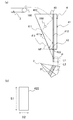
- FIG. 1 (a) is a side view showing a raw material charging device according to an embodiment of the present invention
- FIG. 1 (b) is a plan view for explaining the dimensions of a second opening provided in a discharge port of the raw material charging device.
- FIG. 1 is a side view showing an electronic / electrical device component waste processing device according to an embodiment of the present invention
- FIG. 3 is a partially enlarged plan view of the electronic / electrical device component waste treatment device of FIG. 2.
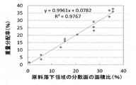
- regulated by the dispersing device. 6 is a photograph showing the dispersion state of the processing raw material when the number of dispersion surfaces provided in the disperser is changed to 0 to 5. It is a graph showing the relationship between the area ratio of the dispersion surface of the raw material falling region and the weight distribution rate of the processing raw material.
- the raw material supply device (raw material chute) 4 As shown in FIG. 1, the raw material supply device (raw material chute) 4 according to the embodiment of the present invention is configured to transfer the raw material 100 containing the substances having different shapes and specific gravities from the transportation means (first transportation means 2) to the first transportation means 2.
- the container 100 is provided with a container 41 for containing the raw material 100 dropped toward the front of the first conveying means 2 and supplying the raw material 100 to a predetermined position.
- the accommodating portion 41 includes an upper surface, a bottom surface facing the upper surface, and a side surface connected to the upper surface and the bottom surface.
- the raw material supply device 4 includes a receiving opening 43 having a first opening 433 for receiving the raw material 100 on the upper surface of the storage section 41, and a second opening 422 for discharging the raw material 100 on the bottom surface of the storage section 41. And a discharge port 42.
- the second opening 422 has a smaller cross-sectional area than the first opening 433.
- the raw material dropped toward the front side of the first conveying means 2 is located on the front side of the side surface of the accommodating portion 41, that is, on the side surface of the storing portion 41 on the front side of the first conveying means 2 that discharges the raw material 100 forward.
- a first guide surface 412 that extends in the vertical direction from the receiving port 43 through the discharge port 42 is provided so as to contact the 100 and guide the raw material 100 downward.
- the material of the first guide surface 412 may be selected so that the first guide surface 412 has such strength that the first guide surface 412 is not deformed even when contacted with scraps of electronic / electrical parts.
- the first guide surface 412 can be formed of an elastic body such as rubber, metal, plastic, or the like.
- a coating or the like may be provided on the surface of the first guide surface 412 to promote the dropping of the raw material 100.
- the first guide surface 412 may be the same as the front side surface of the housing portion 41. On the surface of the side surface of the housing portion 41 facing the first guide surface 412, that is, on the rear side of the side surface of the housing portion 41, an inclined surface 411a that is continuous with the outlet 42 and is inclined with respect to the horizontal plane (HP) is provided. And a second guide surface 411 provided.
- the raw material 100 discharged from the first transfer means 2 drops at least vertically while moving in the horizontal direction by the transfer by the first transfer means 2. At that time, various raw materials 100 are thrown into the receiving port 43 of the raw material supply device 4 while drawing different falling trajectories (parabola) depending on the shapes and specific gravities of the raw materials 100, the degree of solidification of the raw materials 100, and the like. ..
- a part of the raw material 100 which is repelled by the first transporting means 2 and the other raw material 100 and released toward the front side when falling from the first transporting means 2, hits the surface of the first guide surface 412. , Is guided to the lower part of the housing portion 41.
- a part of the raw material 100 then hits the surface of the second guide surface 411 to be the inclined surface 411a and is guided further downward. In this way, the raw material 100 advances downward between the first guide surface 412 and the second guide surface 411, and falls vertically from the second opening 422 of the discharge port 42.
- the second opening 422 of the discharge port 42 has a rectangular shape, and the effective width direction of the transport surface of the first transport unit 2 shown in FIG. ) Has a first dimension S1 that is less than or equal to the effective width of the transport surface of the first transport means 2 in a first direction parallel to the paper surface depth direction), and a second direction orthogonal to the first direction.
- a second dimension S2 is set to be 600 mm or less, for example.
- the second dimension S2 is preferably a dimension that does not cause internal clogging even when the raw material 100 is stored in the storage portion 41, and is 0.5 to 10 times the maximum diameter of the raw material 100, preferably 1 to It is preferably 5 times.
- the shape of the second opening 422 is not limited to a rectangle, and may be an ellipse or a shape in which the corners of the rectangle are rounded, and the specific shape is not limited.
- the first guide surface 412 extending vertically in the housing portion 41 has an extension line whose bottom end extends along the inclination direction of the second guide surface 411.
- the first guide surface 412 extends so as to be located below the intersection P with the first guide surface 412.
- the discharge port 42 may be narrowed and the raw material 100 may be easily clogged. Therefore, the second guide surface 411 is not extended and the first guide surface 411 is not extended. It is preferable to extend only the guide surface 412 of the above.
- the inclination angle ⁇ 2 of the inclined surface 411a of the second guide surface 411 with respect to the horizontal plane HP can be appropriately changed depending on the raw material to be treated.
- the inclination angle ⁇ 2 is preferably 45 to 85 °, and more preferably 50 to 80 °.
- the raw material supply device 4 shown in FIG. 1 is provided with a second transfer means 1 below the first transfer means 2 from a transfer surface 2a of the first transfer means 2 including a conveyor. It can be suitably used for various processing apparatuses that supply raw materials to the transport surface 1a.
- the example of FIG. 2 shows an example applied to a processing device for electronic / electric equipment component waste containing various substances having different shapes and specific gravities.
- the first transporting means 2 and the raw material dropped from the first transporting means 2 to the front thereof are moved to a predetermined position.
- the second transport means 1 a conveyor or the like for transporting the raw material to a sorting unit (sorting machine) for physically sorting the raw material is preferably used.
- the second conveying means 1 has a first width D1 in the direction orthogonal to the raw material conveying direction A.
- the first conveying means 2 has a second width D2 narrower than the first width D1 in the direction orthogonal to the material conveying direction.
- the first width D1 is preferably adjusted so that each width is 2 to 5 times the second width D2, and more preferably, the first width D1 is the second width D2. 2 to 3 times.
- the disperser 3 is provided below the first transfer means 2 on the transfer surface 1a.
- the disperser 3 is provided with a plurality of dispersion surfaces 3a, 3b, 3c, 3d, 3e for radially dispersing the dropped raw material in a plurality of directions.
- five dispersion surfaces 3a to 3e are provided, and each of the dispersion surfaces 3a to 3e has an isosceles triangular shape, but the shape and number are not limited to the following. ..
- the dispersion surfaces 3a to 3e can be about 2 to 10 surfaces, more preferably about 3 to 7 surfaces, and further preferably 3 to 5 surfaces.
- the number of the distribution surfaces 3a to 3e is an odd number.
- the disperser 3 is more preferably aligned and arranged on the transport surface 1a such that one of the plurality of dispersion surfaces 3a to 3e is oriented in the transport direction A of the transport surface 1a. preferable. With such an arrangement, more raw material can be supplied to the front of the disperser 3 (conveying direction) while dispersing the raw material in the width direction.
- the disperser 3 is provided with a plurality of dispersion surfaces 3a to 3e in the raw material conveying direction, and the rear side in the conveyance direction, that is, the back surface portion 3f facing the plurality of dispersion surfaces 3a to 3e is shown in FIG.
- the single surface extends perpendicularly to the transport surface 1a.
- the back surface 3f has the shape of an isosceles triangle that shares the sides of the dispersion surface 3a and the dispersion surface 3e. That is, the disperser 3 has a hexagonal bottom surface, and five dispersive surfaces 3a to 3e extending radially from the top vertex T (see FIG. 3) in the feed direction of the raw material, and from the vertex T to the transport surface 1a. And has a pyramid shape having a back surface portion 3f extending vertically.
- each of the dispersion surfaces 3a to 3e is preferably an inclined surface that inclines at an inclination angle ⁇ 1 with respect to the transport surface 1a.
- the raw material that has dropped from the first conveying means 2 is supplied from the upper side to the lower side of the disperser 3 along this inclined surface, and as shown in FIG. It becomes possible to disperse in the direction of.
- the inclination angle ⁇ 1 formed by the transport surface 1a and the dispersion surfaces 3a to 3e is preferably 30 to 70 °, and more preferably 35 to 50 °.
- a raw material drop region 31 for receiving the raw material falling from the raw material supply device 4 is defined immediately below the raw material discharge port 42 of the raw material supply device 4.
- the raw material dropping region 31 is defined at a position directly below the discharge port 42 of the raw material supply device 4 when the disperser 3 is viewed from the upper surface thereof.
- the raw material dropping region 31 has a rectangular shape similar to the discharge port 42, has a width d2 in the transport direction, and has a width d1 in the direction orthogonal to the transport direction, and the discharge port 42 of the raw material supply device 4 is provided.
- the width d2 in the transport direction of the raw material falling region 31 is set to be the same as or slightly smaller than the second dimension S2.
- the dispersion direction of the raw material by the disperser 3 can be controlled. If the width d2 of the raw material dropping region 31 in the carrying direction is larger than the dimension of the discharge port 42 of the raw material supply device 4, the dispersibility may be deteriorated.
- the shape of the disperser 3 is adjusted so that the area ratios of the plurality of dispersion surfaces 3a to 3e in the raw material falling region 31 are equal to each other.
- the shape of the disperser 3 is adjusted so that the area ratios of the plurality of dispersion surfaces 3a to 3e in the raw material falling region 31 are equal to each other, so that the amount of the raw material falling on each of the dispersion surfaces 3a to 3e is adjusted. Since it is possible to make the dispersion surfaces 3a to 3e uniform, it is possible to more uniformly disperse and supply the raw material on the conveying surface 1a.
- the disperser 3 including the raw material falling area 31 and the raw material supply device 4 are arranged with an appropriate distance from each other.
- the length L1 from the intersection P of the extension line extending along the inclination direction of the second guide surface 411 and the first guide surface 412 to the lowermost end portion of the first guide surface 412. Can be adjusted to be about 0.5 to 1.5 times the maximum diameter of the raw material 100.
- the length L2 from the lowermost end of the first guide surface 412 to the disperser 3 can be adjusted to be about 1.0 to 1.5 times L1.
- the length L2 between the lowermost end of the first guide surface 412 and the disperser 3 is 20 to 100 mm, more preferably 50 to 80 mm, so that the raw material falls within the raw material falling region 31.
- the raw material 100 can be uniformly dispersed from the disperser 3 by dropping the 100 more reliably.
- the raw material supply device 4 and the electronic / electrical equipment component waste treatment device are provided between the first transfer means 2 and the second transfer means 1.
- the raw materials containing substances having different shapes and specific gravities can be collectively dropped at a predetermined position and can be evenly dispersed on the transport surface 1a.
- the raw material supply device 4 and the processing device for electronic / electrical device parts waste shown in FIGS. 1 to 4 are electronic / electrical device parts waste using various sorters such as a wind sorter, a metal sorter, a color sorter, and a sieving machine. Is particularly suitable for application to a sorting process step for sorting.
- the "electronic / electrical device component waste” in the present embodiment is a waste obtained by crushing an electronic / electrical device such as a waste home electric appliance / PC or a mobile phone, and is crushed to an appropriate size after being recovered. It refers to what has been done.
- the crushing to make the electronic / electrical device component waste may be performed by the processor himself, but may be crushed in the city and purchased.
- the crushing method is not limited to a specific device and may be a shearing method or an impact method, but crushing that does not impair the shape of parts is desirable as much as possible. Therefore, devices belonging to the category of crushers intended for fine grinding are not included.
- Electronic / electrical device parts scraps are synthetic resins (plastics) used for substrates, parts such as ICs and connectors, housings, wire scraps, metals, film-like parts scraps, powders generated by crushing and crushing, and others. It is possible to classify into the component waste consisting of, and more finely according to the processing purpose. Although not limited to the following, in the present embodiment, the ratio of the crushed particles having a maximum diameter of 100 mm or less, more typically 50 mm or less, and being separated as a single piece of waste is a weight ratio. With this, 70% or more of electronic / electrical device component waste can be suitably processed.
- a substance unfavorable to the treatment in the copper smelting process for example, antimony (Sb) Raw material in which valuable metals including gold, silver, platinum, palladium and copper are concentrated while reducing elements such as nickel, nickel (Ni) and the like, resins, smelting inhibitors such as aluminum (Al) and iron (Fe) as much as possible Can be obtained.
- Sb antimony
- the sorting treatment step can include at least one of a wind force sorting step, a magnetic force sorting step, an eddy current sorting step, a specific gravity sorting step, and an optical sorting step for optically sorting a metal object and a non-metal object. ..
- the raw material supply device according to the embodiment of the present invention is arranged before the sorter used in these sorting processes.
- a transport surface for transporting electronic / electrical device component waste to the sorter.
- the raw material feeding device 4 shown in FIG. 1 is provided on the plurality of dispersing surfaces 3a to 3e provided in the pyramidal disperser 3 arranged on the conveying surface 1a.
- the electronic / electrical device component scraps are dropped therethrough to disperse the electronic / electrical device component scraps in a plurality of directions on the transport surface 1a.
- the disperser 3 and the raw material supply device 4 together, it is possible to further enhance the dispersibility of the electronic / electrical device component waste on the transport surface 1a. That is, by using the raw material supply device 4 provided right above the disperser 3, the electronic / electrical device component scraps are dropped in the vertical direction from the discharge port of the raw material supply device 4, and the area ratio of the plurality of dispersion surfaces 3a to 3e is reduced. By dropping the electronic / electrical device component scraps on the raw material drop area 31 defined on the disperser 3 formed so that the respective values become equal, the electronic / electrical device component scraps are more uniformly dispersed on the transport surface 1a. Can be made
- the electronic / electrical device component waste when the electronic / electrical device component waste is supplied to the sorter, the electronic / electrical device component waste remains in a lump form without being dispersed. Since it is possible to prevent the sorting machine from being thrown into the sorting machine, it is possible to prevent breakdown and damage of the sorting machine, and it is also possible to prevent deterioration of the sorting efficiency of the sorting machine.
- the present disclosure is not limited to the present embodiment, and constituent elements can be modified and embodied without departing from the gist of the present disclosure. Further, various inventions can be formed by appropriately combining a plurality of constituent elements disclosed in the present embodiment. For example, some constituent elements may be deleted from all the constituent elements shown in this embodiment, or each constituent element may be appropriately combined.
- the raw material supply device 4 may be omitted.
- the processing raw material may drop from the transport surface 1a, or, for example, angular electronic / electrical There is a possibility that scraps of equipment parts may hit the transport surface 1a and damage the transport surface 1a.
- the height between the transport surface 1a and the transport surface 2a of the first transport means 2 is too small, the processing raw material may not be well dispersed on the transport surface 1a and may be concentrated.
- the height of the transport surface 2a of the first transport means 2 with respect to the transport surface 1a is preferably 1.0 to 2.0 m, and typically 1.2 to 1.6 m.
- the raw material supply device 4 shown in FIG. 1 was produced in order to centrally drop the raw material in a specific range in the vertical direction and drop the raw material. It is assumed that the effective width of the conveyor surface above the raw material supply device 4 is 600 mm, the maximum diameter of the raw material is 50 to 70 mm, and the raw material transport speed is 36 m / min.
- the raw materials are electronic materials consisting of substrates, parts such as ICs and connectors, synthetic resins (plastics) used for housings, wire scraps, metals, film-like parts scraps, powders produced by crushing and crushing, and others. -Electrical equipment parts scraps and an aluminum plate (20 mm x 50 mm x 0.5 mm) were used.
- the size of the first opening 433 provided in the receiving port 43 was designed to be 600 mm ⁇ 320 mm.
- the first dimension S1 of the second opening 422 provided in the discharge port 42 was designed to be 600 mm and the second dimension was designed to be 50 mm.
- the length L1 from the intersection point P of the extension line extending along the inclination direction of the second guide surface 411 and the first guide surface 412 to the lowermost end portion of the first guide surface 412 is set to 50 mm
- the length L2 from the lowermost end of the guide surface 412 to the disperser 3 was set to 70 mm, and the position was adjusted so that the raw material dropping area 31 of the disperser 3 was located immediately below the second opening 422 provided in the discharge port 42.
- the inclination angle ⁇ 2 of the inclined surface 411a of the second guide surface 411 was 70 °.
- Dispersers having different numbers of dispersion surfaces were prepared and the dispersion behavior of the processing raw materials was evaluated.
- the disperser was made of plastic corrugated board, and the dispersion surface was 2-5.
- Each dispersion surface was an isosceles triangle, and the bases of the triangles were equal.
- the inclination angle of each dispersion surface with respect to the bottom surface of the disperser was designed to be 45 °.
- An aluminum plate (20 ⁇ 50 ⁇ 0.5 mm) was used as a processing raw material for easy evaluation. Results are shown in FIG.
- the distribution rate (%) represents the ratio of the weight of the raw material dispersed on each dispersion surface to the total weight of the raw material.
- the error (%) represents an error with respect to an ideal value when the entire raw material is evenly dispersed on each dispersion surface.
- the error of the distribution rate can be achieved within 10%, and the disperser and the raw material supply device according to the present embodiment. It can be seen that by using the method, it was possible to disperse the particles more uniformly on the transport surface 1a.
Landscapes
- Engineering & Computer Science (AREA)
- Mechanical Engineering (AREA)
- Filling Or Emptying Of Bunkers, Hoppers, And Tanks (AREA)
- Feeding Of Articles To Conveyors (AREA)
- Sorting Of Articles (AREA)
- Chutes (AREA)
- Combined Means For Separation Of Solids (AREA)
- Manufacture And Refinement Of Metals (AREA)
- Processing Of Solid Wastes (AREA)
Abstract
Description
本発明の実施の形態に係る原料供給装置(原料シュート)4は、図1に示すように、形状及び比重の異なる物質を含む原料100を搬送する搬送手段(第1の搬送手段2)から第1の搬送手段2の前方へ向けて投下される原料100を収容し、原料100を予め定められた位置へと供給する収容部41を備える。収容部41は上面と上面に対向する底面と、上面及び底面に接続された側面を備える。
図1に示す原料供給装置4は、図2に示すように、コンベアなどからなる第1の搬送手段2の搬送面2aから、第1の搬送手段2の下方にある第2の搬送手段1の搬送面1aへと原料を供給するような種々の処理装置に対して好適に用いることができる。図2の例では、形状及び比重の異なる種々の物質を含む電子・電気機器部品屑の処理装置に適用した例を示している。
図1~図4に示す原料供給装置4及び電子・電気機器部品屑の処理装置は、風力選別機、メタルソータ、カラーソータ、篩別機などの種々の選別機を用いた電子・電気機器部品屑を選別するための選別処理工程への適用に特に好適である。
原料を垂直方向の特定範囲に集約して落下させるために、図1に示す原料供給装置4を作製した。原料供給装置4の上方にあるコンベアの搬送面の有効幅を600mm、原料の最大直径を50~70mm、原料の搬送速度を36m/minと想定した。原料としては、基板、ICやコネクタ等のパーツ、筐体などに使われる合成樹脂類(プラスチック)、線屑、メタル、フィルム状部品屑、破砕や粉砕によって生じる粉状物、その他、からなる電子・電気機器部品屑と、アルミ板(20mm×50mm×0.5mm)を使用した。受入口43が備える第1の開口433の寸法を600mm×320mmと設計した。排出口42が備える第2の開口422の第1の寸法S1を600mm、第2の寸法を50mmと設計した。第2の案内面411の傾斜方向に沿って延長した延長線と第1の案内面412との交点Pから第1の案内面412の最下端部までの長さL1を50mmとし、第1の案内面412の最下端部から分散器3までの長さL2を70mmとし、排出口42が備える第2の開口422の直下に分散器3の原料落下領域31がくるように位置を調節した。なお、第2の案内面411の傾斜面411aの傾斜角度θ2は、70°とした。
分散面の数が異なる分散器を作製し、処理原料の分散挙動を評価した。分散器はプラスチック段ボール製で、分散面が2~5面のものを作製した。各分散面は二等辺三角形とし、各三角形の底辺をそれぞれ等しくした。分散器の底面に対する各分散面の傾斜角度を45°で設計した。処理原料としては、評価を容易にするために、アルミ板(20×50×0.5mm)を使用した。結果を図5に示す。

図1に示す処理装置において、搬送速度36m/minの第1の搬送手段から、原料として、電子・電気機器部品屑とアルミ片とを原料供給装置4へ向けて落下させて、分散器3から第2の搬送手段1上の搬送面1a上に原料を分散させた。分散器3が備える各分散面3a~3e(図4のA~E)を沿って搬送面1a上へ落下した原料の重量をそれぞれ求めた。結果を表2に示す。

1a…搬送面
2…第1の搬送手段
2a…搬送面
3…分散器
3a~3e…分散面
4…原料供給装置
31…原料落下領域
41…収容部
42…排出口
43…受入口
411…第2の案内面
411a…傾斜面
412…第1の案内面
422…第2の開口
433…第1の開口
Claims (8)
- 形状及び比重の異なる物質を含む原料を搬送する搬送手段から前記搬送手段の前方へ向けて投下される前記原料を収容し、前記原料を予め定められた位置へと供給する収容部を備える原料供給装置であって、
前記収容部の上面に前記原料を受け入れるための第1の開口を備える受入口と、
前記収容部の底面に前記原料を排出するための前記第1の開口よりも小さい断面積を有する第2の開口を備える排出口と、
前記収容部の側面前方に、前記搬送手段の前方へ向けて投下された前記原料と接触して前記原料を下方へ案内するように、前記受入口から前記排出口を突き抜けて垂直方向に延びる第1の案内面と、
前記収容部の側面の前記第1の案内面と対向する面に、前記排出口と連続し、水平面に対して傾斜する傾斜面を備えた第2の案内面と
を備え、
前記第1の案内面の最下端部が、前記第2の案内面の傾斜方向に沿って延長した延長線と前記第1の案内面との交点よりも下方に位置するように、前記第1の案内面が延びていることを特徴とする原料供給装置。 - 前記第2の開口が、前記搬送手段の搬送面の有効幅方向と並行な第1の方向に前記搬送面の有効幅以下となる第1の寸法を有し、前記第1の方向と直交する第2の方向に前記原料の最大直径の0.5~10倍となる第2の寸法を有することを特徴とする請求項1に記載の原料供給装置。
- 形状及び比重の異なる物質を含む原料を搬送する第1の搬送手段と、
前記第1の搬送手段の下方に設けられ、前記原料を処理するための処理装置へ前記原料を搬送するための第2の搬送手段と、
前記第2の搬送手段の搬送面上に配置され、前記第1の搬送手段から供給される前記原料を受けるための原料落下領域を備え、前記原料落下領域に落下した前記原料を、前記第2の搬送手段の前記搬送面上の複数の方向に分散させるための複数の分散面を備える角錐状の分散器と
を備えることを特徴とする原料供給装置。 - 形状及び比重の異なる物質を含む原料を搬送する第1の搬送手段と、
前記第1の搬送手段からその前方へ投下された前記原料を予め定められた位置へと供給する請求項1又は2に記載の原料供給装置と、
前記原料供給装置の下方に設けられ、前記原料を処理するための処理装置へ前記原料を搬送するための第2の搬送手段と、
前記第2の搬送手段の搬送面上に配置され、前記原料供給装置から供給された前記原料を前記第2の搬送手段の前記搬送面上の複数の方向に分散させるための複数の分散面を備える角錐状の分散器と
を備えることを特徴とする電子・電気機器部品屑の処理装置。 - 前記分散器は、前記原料供給装置の排出口の下方に、前記原料供給装置から落下した前記原料を受けるための原料落下領域を有し、前記原料落下領域における前記複数の分散面の面積比がそれぞれ等しくなるように配置されていること特徴とする請求項4に記載の電子・電気機器部品屑の処理装置。
- 第1の案内面の最下端部と前記分散器とを20~100mm離間させて配置することを特徴とする請求項4又は5に記載の電子・電気機器部品屑の処理装置。
- 選別機を用いて電子・電気機器部品屑を選別するための選別処理工程を含む電子・電気機器部品屑の処理方法において、角錐状の分散器が備える複数の分散面上に、前記電子・電気機器部品屑を落下させ、前記電子・電気機器部品屑を前記選別機へ搬送するための搬送面上の複数の方向へ分散させることを含む電子・電気機器部品屑の処理方法。
- 請求項1又は2に記載の原料供給装置を介して前記分散器上に前記電子・電気機器部品屑を供給することを含む請求項7に記載の電子・電気機器部品屑の処理方法。
Priority Applications (5)
| Application Number | Priority Date | Filing Date | Title |
|---|---|---|---|
| US17/290,044 US11649119B2 (en) | 2018-10-31 | 2019-10-30 | Raw material supply device, device for processing electronic and electrical device part scraps, and method for processing electronic and electrical device part scraps |
| KR1020217016178A KR102524815B1 (ko) | 2018-10-31 | 2019-10-30 | 원료 공급 장치, 전자·전기 기기 부품 스크랩의 처리 장치 및 전자·전기 기기 부품 스크랩의 처리 방법 |
| EP19878249.2A EP3875407A4 (en) | 2018-10-31 | 2019-10-30 | RAW MATERIAL FEEDER, ELECTRONIC AND ELECTRICAL WASTE PROCESSING DEVICE, AND ELECTRONIC AND ELECTRICAL WASTE PROCESSING METHOD |
| CA3118063A CA3118063C (en) | 2018-10-31 | 2019-10-30 | Raw material supply device, device for processing electronic and electrical device part scraps, and method for processing electronic and electrical device part scraps |
| CN201980071140.9A CN112930313B (zh) | 2018-10-31 | 2019-10-30 | 原料供给装置、电子/电气设备部件屑的处理装置及电子/电气设备部件屑的处理方法 |
Applications Claiming Priority (2)
| Application Number | Priority Date | Filing Date | Title |
|---|---|---|---|
| JP2018206162A JP6938450B2 (ja) | 2018-10-31 | 2018-10-31 | 原料供給装置、電子・電気機器部品屑の処理装置及び電子・電気機器部品屑の処理方法 |
| JP2018-206162 | 2018-10-31 |
Publications (1)
| Publication Number | Publication Date |
|---|---|
| WO2020090942A1 true WO2020090942A1 (ja) | 2020-05-07 |
Family
ID=70462453
Family Applications (1)
| Application Number | Title | Priority Date | Filing Date |
|---|---|---|---|
| PCT/JP2019/042697 Ceased WO2020090942A1 (ja) | 2018-10-31 | 2019-10-30 | 原料供給装置、電子・電気機器部品屑の処理装置及び電子・電気機器部品屑の処理方法 |
Country Status (8)
| Country | Link |
|---|---|
| US (1) | US11649119B2 (ja) |
| EP (1) | EP3875407A4 (ja) |
| JP (1) | JP6938450B2 (ja) |
| KR (1) | KR102524815B1 (ja) |
| CN (1) | CN112930313B (ja) |
| CA (1) | CA3118063C (ja) |
| TW (2) | TWI730483B (ja) |
| WO (1) | WO2020090942A1 (ja) |
Families Citing this family (4)
| Publication number | Priority date | Publication date | Assignee | Title |
|---|---|---|---|---|
| JP6938450B2 (ja) * | 2018-10-31 | 2021-09-22 | Jx金属株式会社 | 原料供給装置、電子・電気機器部品屑の処理装置及び電子・電気機器部品屑の処理方法 |
| JP7627168B2 (ja) * | 2021-04-21 | 2025-02-05 | Jx金属株式会社 | 電気電子部品屑の処理方法 |
| JP7264936B2 (ja) * | 2021-04-21 | 2023-04-25 | Jx金属株式会社 | 電気電子部品屑の処理方法及び電気電子部品屑の処理装置 |
| CN115231190B (zh) * | 2022-08-18 | 2024-03-08 | 酒泉钢铁(集团)有限责任公司 | 一种用于干磨干选机的均匀化给料方法 |
Citations (7)
| Publication number | Priority date | Publication date | Assignee | Title |
|---|---|---|---|---|
| JPS5539953U (ja) * | 1978-09-05 | 1980-03-14 | ||
| JPS60126440U (ja) * | 1984-01-31 | 1985-08-26 | 小川 周一 | 拡散供給機 |
| JPS6412020U (ja) * | 1987-07-14 | 1989-01-23 | ||
| JPH07228319A (ja) * | 1994-02-16 | 1995-08-29 | Tokai Rubber Ind Ltd | シュートの内壁保護装置 |
| JPH08131953A (ja) * | 1994-11-02 | 1996-05-28 | Fuji Car Mfg Co Ltd | 廃棄物の分離方法及びその装置 |
| JP2009240846A (ja) | 2008-03-28 | 2009-10-22 | Nichikon Seisakusho:Kk | アルミニウムのリサイクル処理装置 |
| JP2012012148A (ja) * | 2010-06-30 | 2012-01-19 | Nippon Steel Corp | スラグ搬送装置 |
Family Cites Families (33)
| Publication number | Priority date | Publication date | Assignee | Title |
|---|---|---|---|---|
| DE2119311A1 (de) * | 1971-04-21 | 1972-11-02 | Hauni-Werke Körber & Co KG, 2000 Hamburg | Verfahren und Vorrichtung zum Entnehmen von stabförmigen Artikeln |
| JPS5224936Y2 (ja) * | 1971-09-21 | 1977-06-07 | ||
| US4031004A (en) * | 1976-05-24 | 1977-06-21 | Sommer Jr Edward J | Feed system for an electromagnetic eddy current materials separator |
| US4183192A (en) * | 1978-03-03 | 1980-01-15 | Marcal Paper Mills, Inc. | Method and apparatus for counting straws and the like |
| DE2942163A1 (de) * | 1979-10-18 | 1981-04-30 | Carl Schenck Ag, 6100 Darmstadt | Verfahren und vorrichtung zum aufteilen eines foerderstromes |
| JPS59144532U (ja) * | 1983-03-16 | 1984-09-27 | 大和製衡株式会社 | 組合わせ秤用分散フイ−ダ |
| JPS6079125U (ja) * | 1983-11-07 | 1985-06-01 | 株式会社石田衡器製作所 | 自動計量装置の集合シユ−ト |
| US4693355A (en) | 1984-11-12 | 1987-09-15 | Ishida Scales Mfg. Co., Ltd. | Automatic combinatorial weighting apparatus |
| DE3615769C1 (de) * | 1986-05-10 | 1987-05-27 | Orenstein & Koppel Ag | Foerderbandanlage mit Abwurftrommel |
| KR960003772B1 (ko) * | 1992-08-24 | 1996-03-22 | 현대전자산업주식회사 | 반도체 소자의 캐패시터 제조방법 |
| US5553968A (en) * | 1994-09-29 | 1996-09-10 | Astec Industries, Inc. | Method and apparatus for conveying and desegregating aggregate |
| EP0800902B1 (de) * | 1996-04-11 | 2002-03-06 | Dieffenbacher Schenck Panel GmbH | Verfahren zur kontinuierlichen Herstellung eines Vlieses für die Herstellung von Holzwerkstoff- oder ähnlichen Platten |
| DE29707143U1 (de) * | 1997-04-21 | 1997-07-03 | Kvaerner Panel Systems GmbH Maschinen- und Anlagenbau, 31832 Springe | Vorrichtung zum Ausrichten und Ablegen von länglichen Teilchen wie Holzspänen, Holzfasern o.dgl. auf einer kontinuierlich bewegten Unterlage |
| US6290055B1 (en) * | 1997-09-09 | 2001-09-18 | Paul Glorfield | Device for orienting and achieving the optimal density of a quantity of elongated objects |
| ES2155720T3 (es) * | 1997-11-05 | 2001-05-16 | Kramer Ag Bassersdorf | Transportador por vibraciones con un sistema de conmutacion de canales de distribucion. |
| US6135171A (en) * | 1999-03-18 | 2000-10-24 | Weakly; L. Alan | Passive enclosure dust control system |
| JP3591412B2 (ja) * | 1999-05-31 | 2004-11-17 | 松下電器産業株式会社 | 破砕装置 |
| US20030127302A1 (en) * | 2001-01-31 | 2003-07-10 | Brewer Marvin Vincent | Regulatory gate system for product drop off of vibratory conveyors |
| KR100770300B1 (ko) * | 2001-11-19 | 2007-10-25 | 주식회사 포스코 | 선별스크린에서의 광석분산장치 |
| US7063215B2 (en) * | 2002-06-24 | 2006-06-20 | Campbell Soup Company | Control systems and methods of dispensing items |
| TWM247566U (en) | 2003-11-25 | 2004-10-21 | Mei-Yun Li | Curved type transferring and connecting apparatus |
| US7228956B2 (en) * | 2005-01-10 | 2007-06-12 | Benetech, Inc. | Bulk material precision transfer chute apparatus |
| CN102510832B (zh) * | 2009-07-09 | 2014-06-18 | 康尼格拉食品蓝姆威斯顿公司 | 物品分配和分类系统 |
| JP2011162271A (ja) | 2010-02-04 | 2011-08-25 | Mitsubishi Electric Corp | バラ物搬送装置 |
| JP5574876B2 (ja) * | 2010-08-11 | 2014-08-20 | 鎌長製衡株式会社 | 石膏廃材再生原料化装置 |
| JP5672182B2 (ja) * | 2011-07-14 | 2015-02-18 | トヨタ自動車株式会社 | ナット並べ装置 |
| CN102357468B (zh) * | 2011-08-03 | 2014-02-05 | 合肥美亚光电技术股份有限公司 | 色选机均匀布料装置 |
| WO2013061374A1 (ja) * | 2011-10-27 | 2013-05-02 | 大和製衡株式会社 | 組合せ秤の被計量物集合排出装置及びこれを用いた組合せ秤 |
| CN203143656U (zh) * | 2012-12-30 | 2013-08-21 | 衡阳运输机械有限公司 | 一种改良结构的受料斗 |
| JP5873989B2 (ja) * | 2013-04-25 | 2016-03-01 | パナソニックIpマネジメント株式会社 | 物質の選別装置、選別方法 |
| CN205590014U (zh) | 2016-04-08 | 2016-09-21 | 广东韶钢松山股份有限公司 | 一种挡板式高效溜槽 |
| US10099525B1 (en) * | 2018-06-20 | 2018-10-16 | Cal M. Phillips | Trailer hitch drawbar tightening mechanism |
| JP6938450B2 (ja) * | 2018-10-31 | 2021-09-22 | Jx金属株式会社 | 原料供給装置、電子・電気機器部品屑の処理装置及び電子・電気機器部品屑の処理方法 |
-
2018
- 2018-10-31 JP JP2018206162A patent/JP6938450B2/ja active Active
-
2019
- 2019-10-30 US US17/290,044 patent/US11649119B2/en active Active
- 2019-10-30 EP EP19878249.2A patent/EP3875407A4/en not_active Withdrawn
- 2019-10-30 WO PCT/JP2019/042697 patent/WO2020090942A1/ja not_active Ceased
- 2019-10-30 CA CA3118063A patent/CA3118063C/en active Active
- 2019-10-30 KR KR1020217016178A patent/KR102524815B1/ko active Active
- 2019-10-30 CN CN201980071140.9A patent/CN112930313B/zh active Active
- 2019-10-31 TW TW108139490A patent/TWI730483B/zh active
- 2019-10-31 TW TW110116370A patent/TWI794806B/zh active
Patent Citations (7)
| Publication number | Priority date | Publication date | Assignee | Title |
|---|---|---|---|---|
| JPS5539953U (ja) * | 1978-09-05 | 1980-03-14 | ||
| JPS60126440U (ja) * | 1984-01-31 | 1985-08-26 | 小川 周一 | 拡散供給機 |
| JPS6412020U (ja) * | 1987-07-14 | 1989-01-23 | ||
| JPH07228319A (ja) * | 1994-02-16 | 1995-08-29 | Tokai Rubber Ind Ltd | シュートの内壁保護装置 |
| JPH08131953A (ja) * | 1994-11-02 | 1996-05-28 | Fuji Car Mfg Co Ltd | 廃棄物の分離方法及びその装置 |
| JP2009240846A (ja) | 2008-03-28 | 2009-10-22 | Nichikon Seisakusho:Kk | アルミニウムのリサイクル処理装置 |
| JP2012012148A (ja) * | 2010-06-30 | 2012-01-19 | Nippon Steel Corp | スラグ搬送装置 |
Non-Patent Citations (1)
| Title |
|---|
| See also references of EP3875407A4 |
Also Published As
| Publication number | Publication date |
|---|---|
| TW202136134A (zh) | 2021-10-01 |
| KR20210082235A (ko) | 2021-07-02 |
| TWI730483B (zh) | 2021-06-11 |
| JP2020070165A (ja) | 2020-05-07 |
| CN112930313B (zh) | 2022-09-13 |
| US11649119B2 (en) | 2023-05-16 |
| CA3118063C (en) | 2024-01-09 |
| TW202033427A (zh) | 2020-09-16 |
| TWI794806B (zh) | 2023-03-01 |
| EP3875407A4 (en) | 2022-07-27 |
| EP3875407A1 (en) | 2021-09-08 |
| JP6938450B2 (ja) | 2021-09-22 |
| KR102524815B1 (ko) | 2023-04-24 |
| CA3118063A1 (en) | 2020-05-07 |
| CN112930313A (zh) | 2021-06-08 |
| US20210403247A1 (en) | 2021-12-30 |
Similar Documents
| Publication | Publication Date | Title |
|---|---|---|
| WO2020090942A1 (ja) | 原料供給装置、電子・電気機器部品屑の処理装置及び電子・電気機器部品屑の処理方法 | |
| JP7155453B2 (ja) | 線状物の除去方法、線状物の除去装置及び電子・電気機器部品屑の処理方法 | |
| JP7438261B2 (ja) | 線状物の除去方法 | |
| CN112638551A (zh) | 线状物的去除方法、线状物的去除装置及电子、电气设备部件屑的处理方法 | |
| US12090518B2 (en) | Method for processing electronic and electric device component scraps | |
| JP6859151B2 (ja) | 電子・電気機器部品屑の処理方法 | |
| JP2020037459A (ja) | 原料供給装置及び電子・電気機器部品屑の処理方法 | |
| CN113677444B (zh) | 电子/电气设备部件屑的处理方法 | |
| JP4637625B2 (ja) | 選別装置および樹脂リサイクル方法 | |
| CA3142590C (en) | Raw material discharge device, method of processing of electronic/electrical device component scrap, and method of raw material discharge for electronic/electrical device componentscrap | |
| JP7761279B2 (ja) | 金属被膜樹脂材の金属と樹脂材の分離回収方法及びその分離回収装置 | |
| JP2023035563A (ja) | 供給装置 | |
| JP2017115202A (ja) | 焼結原料の造粒方法及び造粒設備 | |
| TW202039104A (zh) | 揀選機及電子/電氣機器零件屑之處理方法 |
Legal Events
| Date | Code | Title | Description |
|---|---|---|---|
| 121 | Ep: the epo has been informed by wipo that ep was designated in this application |
Ref document number: 19878249 Country of ref document: EP Kind code of ref document: A1 |
|
| ENP | Entry into the national phase |
Ref document number: 3118063 Country of ref document: CA |
|
| NENP | Non-entry into the national phase |
Ref country code: DE |
|
| ENP | Entry into the national phase |
Ref document number: 20217016178 Country of ref document: KR Kind code of ref document: A |
|
| ENP | Entry into the national phase |
Ref document number: 2019878249 Country of ref document: EP Effective date: 20210531 |