WO2020095081A1 - 内燃機関の制御方法および制御装置 - Google Patents
内燃機関の制御方法および制御装置 Download PDFInfo
- Publication number
- WO2020095081A1 WO2020095081A1 PCT/IB2018/001331 IB2018001331W WO2020095081A1 WO 2020095081 A1 WO2020095081 A1 WO 2020095081A1 IB 2018001331 W IB2018001331 W IB 2018001331W WO 2020095081 A1 WO2020095081 A1 WO 2020095081A1
- Authority
- WO
- WIPO (PCT)
- Prior art keywords
- compression ratio
- internal combustion
- combustion engine
- stop
- restart
- Prior art date
- Legal status (The legal status is an assumption and is not a legal conclusion. Google has not performed a legal analysis and makes no representation as to the accuracy of the status listed.)
- Ceased
Links
Images


Classifications
-
- F—MECHANICAL ENGINEERING; LIGHTING; HEATING; WEAPONS; BLASTING
- F02—COMBUSTION ENGINES; HOT-GAS OR COMBUSTION-PRODUCT ENGINE PLANTS
- F02D—CONTROLLING COMBUSTION ENGINES
- F02D15/00—Varying compression ratio
- F02D15/02—Varying compression ratio by alteration or displacement of piston stroke
-
- B—PERFORMING OPERATIONS; TRANSPORTING
- B60—VEHICLES IN GENERAL
- B60W—CONJOINT CONTROL OF VEHICLE SUB-UNITS OF DIFFERENT TYPE OR DIFFERENT FUNCTION; CONTROL SYSTEMS SPECIALLY ADAPTED FOR HYBRID VEHICLES; ROAD VEHICLE DRIVE CONTROL SYSTEMS FOR PURPOSES NOT RELATED TO THE CONTROL OF A PARTICULAR SUB-UNIT
- B60W10/00—Conjoint control of vehicle sub-units of different type or different function
- B60W10/02—Conjoint control of vehicle sub-units of different type or different function including control of driveline clutches
-
- B—PERFORMING OPERATIONS; TRANSPORTING
- B60—VEHICLES IN GENERAL
- B60W—CONJOINT CONTROL OF VEHICLE SUB-UNITS OF DIFFERENT TYPE OR DIFFERENT FUNCTION; CONTROL SYSTEMS SPECIALLY ADAPTED FOR HYBRID VEHICLES; ROAD VEHICLE DRIVE CONTROL SYSTEMS FOR PURPOSES NOT RELATED TO THE CONTROL OF A PARTICULAR SUB-UNIT
- B60W10/00—Conjoint control of vehicle sub-units of different type or different function
- B60W10/04—Conjoint control of vehicle sub-units of different type or different function including control of propulsion units
- B60W10/06—Conjoint control of vehicle sub-units of different type or different function including control of propulsion units including control of combustion engines
-
- B—PERFORMING OPERATIONS; TRANSPORTING
- B60—VEHICLES IN GENERAL
- B60W—CONJOINT CONTROL OF VEHICLE SUB-UNITS OF DIFFERENT TYPE OR DIFFERENT FUNCTION; CONTROL SYSTEMS SPECIALLY ADAPTED FOR HYBRID VEHICLES; ROAD VEHICLE DRIVE CONTROL SYSTEMS FOR PURPOSES NOT RELATED TO THE CONTROL OF A PARTICULAR SUB-UNIT
- B60W30/00—Purposes of road vehicle drive control systems not related to the control of a particular sub-unit, e.g. of systems using conjoint control of vehicle sub-units
- B60W30/18—Propelling the vehicle
- B60W30/18009—Propelling the vehicle related to particular drive situations
- B60W30/18018—Start-stop drive, e.g. in a traffic jam
-
- B—PERFORMING OPERATIONS; TRANSPORTING
- B63—SHIPS OR OTHER WATERBORNE VESSELS; RELATED EQUIPMENT
- B63H—MARINE PROPULSION OR STEERING
- B63H21/00—Use of propulsion power plant or units on vessels
- B63H21/21—Control means for engine or transmission, specially adapted for use on marine vessels
-
- B—PERFORMING OPERATIONS; TRANSPORTING
- B63—SHIPS OR OTHER WATERBORNE VESSELS; RELATED EQUIPMENT
- B63H—MARINE PROPULSION OR STEERING
- B63H23/00—Transmitting power from propulsion power plant to propulsive elements
- B63H23/30—Transmitting power from propulsion power plant to propulsive elements characterised by use of clutches
-
- F—MECHANICAL ENGINEERING; LIGHTING; HEATING; WEAPONS; BLASTING
- F02—COMBUSTION ENGINES; HOT-GAS OR COMBUSTION-PRODUCT ENGINE PLANTS
- F02B—INTERNAL-COMBUSTION PISTON ENGINES; COMBUSTION ENGINES IN GENERAL
- F02B75/00—Other engines
- F02B75/04—Engines with variable distances between pistons at top dead-centre positions and cylinder heads
- F02B75/047—Engines with variable distances between pistons at top dead-centre positions and cylinder heads by means of variable crankshaft position
-
- F—MECHANICAL ENGINEERING; LIGHTING; HEATING; WEAPONS; BLASTING
- F02—COMBUSTION ENGINES; HOT-GAS OR COMBUSTION-PRODUCT ENGINE PLANTS
- F02D—CONTROLLING COMBUSTION ENGINES
- F02D41/00—Electrical control of supply of combustible mixture or its constituents
- F02D41/02—Circuit arrangements for generating control signals
- F02D41/04—Introducing corrections for particular operating conditions
- F02D41/042—Introducing corrections for particular operating conditions for stopping the engine
-
- B—PERFORMING OPERATIONS; TRANSPORTING
- B60—VEHICLES IN GENERAL
- B60W—CONJOINT CONTROL OF VEHICLE SUB-UNITS OF DIFFERENT TYPE OR DIFFERENT FUNCTION; CONTROL SYSTEMS SPECIALLY ADAPTED FOR HYBRID VEHICLES; ROAD VEHICLE DRIVE CONTROL SYSTEMS FOR PURPOSES NOT RELATED TO THE CONTROL OF A PARTICULAR SUB-UNIT
- B60W30/00—Purposes of road vehicle drive control systems not related to the control of a particular sub-unit, e.g. of systems using conjoint control of vehicle sub-units
- B60W30/18—Propelling the vehicle
- B60W30/18009—Propelling the vehicle related to particular drive situations
- B60W30/18072—Coasting
- B60W2030/1809—Without torque flow between driveshaft and engine, e.g. with clutch disengaged or transmission in neutral
-
- B—PERFORMING OPERATIONS; TRANSPORTING
- B63—SHIPS OR OTHER WATERBORNE VESSELS; RELATED EQUIPMENT
- B63H—MARINE PROPULSION OR STEERING
- B63H21/00—Use of propulsion power plant or units on vessels
- B63H21/21—Control means for engine or transmission, specially adapted for use on marine vessels
- B63H2021/216—Control means for engine or transmission, specially adapted for use on marine vessels using electric control means
-
- F—MECHANICAL ENGINEERING; LIGHTING; HEATING; WEAPONS; BLASTING
- F02—COMBUSTION ENGINES; HOT-GAS OR COMBUSTION-PRODUCT ENGINE PLANTS
- F02D—CONTROLLING COMBUSTION ENGINES
- F02D2200/00—Input parameters for engine control
- F02D2200/50—Input parameters for engine control said parameters being related to the vehicle or its components
- F02D2200/501—Vehicle speed
-
- F—MECHANICAL ENGINEERING; LIGHTING; HEATING; WEAPONS; BLASTING
- F02—COMBUSTION ENGINES; HOT-GAS OR COMBUSTION-PRODUCT ENGINE PLANTS
- F02D—CONTROLLING COMBUSTION ENGINES
- F02D29/00—Controlling engines, such controlling being peculiar to the devices driven thereby, the devices being other than parts or accessories essential to engine operation, e.g. controlling of engines by signals external thereto
- F02D29/02—Controlling engines, such controlling being peculiar to the devices driven thereby, the devices being other than parts or accessories essential to engine operation, e.g. controlling of engines by signals external thereto peculiar to engines driving vehicles; peculiar to engines driving variable pitch propellers
-
- F—MECHANICAL ENGINEERING; LIGHTING; HEATING; WEAPONS; BLASTING
- F02—COMBUSTION ENGINES; HOT-GAS OR COMBUSTION-PRODUCT ENGINE PLANTS
- F02D—CONTROLLING COMBUSTION ENGINES
- F02D41/00—Electrical control of supply of combustible mixture or its constituents
- F02D41/02—Circuit arrangements for generating control signals
- F02D41/04—Introducing corrections for particular operating conditions
- F02D41/06—Introducing corrections for particular operating conditions for engine starting or warming up
- F02D41/062—Introducing corrections for particular operating conditions for engine starting or warming up for starting
- F02D41/064—Introducing corrections for particular operating conditions for engine starting or warming up for starting at cold start
-
- F—MECHANICAL ENGINEERING; LIGHTING; HEATING; WEAPONS; BLASTING
- F02—COMBUSTION ENGINES; HOT-GAS OR COMBUSTION-PRODUCT ENGINE PLANTS
- F02N—STARTING OF COMBUSTION ENGINES; STARTING AIDS FOR SUCH ENGINES, NOT OTHERWISE PROVIDED FOR
- F02N11/00—Starting of engines by means of electric motors
- F02N11/08—Circuits specially adapted for starting of engines
- F02N11/0814—Circuits specially adapted for starting of engines comprising means for controlling automatic idle-start-stop
- F02N11/0818—Conditions for starting or stopping the engine or for deactivating the idle-start-stop mode
-
- F—MECHANICAL ENGINEERING; LIGHTING; HEATING; WEAPONS; BLASTING
- F02—COMBUSTION ENGINES; HOT-GAS OR COMBUSTION-PRODUCT ENGINE PLANTS
- F02N—STARTING OF COMBUSTION ENGINES; STARTING AIDS FOR SUCH ENGINES, NOT OTHERWISE PROVIDED FOR
- F02N2300/00—Control related aspects of engine starting
- F02N2300/20—Control related aspects of engine starting characterised by the control method
- F02N2300/2002—Control related aspects of engine starting characterised by the control method using different starting modes, methods, or actuators depending on circumstances, e.g. engine temperature or component wear
-
- F—MECHANICAL ENGINEERING; LIGHTING; HEATING; WEAPONS; BLASTING
- F02—COMBUSTION ENGINES; HOT-GAS OR COMBUSTION-PRODUCT ENGINE PLANTS
- F02N—STARTING OF COMBUSTION ENGINES; STARTING AIDS FOR SUCH ENGINES, NOT OTHERWISE PROVIDED FOR
- F02N5/00—Starting apparatus having mechanical power storage
- F02N5/04—Starting apparatus having mechanical power storage of inertia type
-
- Y—GENERAL TAGGING OF NEW TECHNOLOGICAL DEVELOPMENTS; GENERAL TAGGING OF CROSS-SECTIONAL TECHNOLOGIES SPANNING OVER SEVERAL SECTIONS OF THE IPC; TECHNICAL SUBJECTS COVERED BY FORMER USPC CROSS-REFERENCE ART COLLECTIONS [XRACs] AND DIGESTS
- Y02—TECHNOLOGIES OR APPLICATIONS FOR MITIGATION OR ADAPTATION AGAINST CLIMATE CHANGE
- Y02T—CLIMATE CHANGE MITIGATION TECHNOLOGIES RELATED TO TRANSPORTATION
- Y02T10/00—Road transport of goods or passengers
- Y02T10/10—Internal combustion engine [ICE] based vehicles
- Y02T10/40—Engine management systems
Definitions
- the present invention relates to a control method and a control device for an internal combustion engine provided with a variable compression ratio mechanism capable of changing a mechanical compression ratio, and particularly to a compression method for stopping an internal combustion engine called sailing stop during coasting of a vehicle. Regarding ratio control.
- variable compression ratio mechanisms In the field of internal combustion engines, various types of variable compression ratio mechanisms have been conventionally known. For example, a variable compression ratio mechanism that changes the mechanical compression ratio by changing the relative positional relationship between the piston and the cylinder, and a type that changes the volume of the combustion chamber with an auxiliary piston / cylinder are widely known. ing.
- the target compression ratio is set based on the operating conditions of the internal combustion engine, that is, the load and the rotation speed, and the target compression ratio becomes lower as the load increases.
- Patent Document 1 discloses an internal combustion engine having a so-called idle stop function that automatically stops the internal combustion engine when the vehicle stops at an intersection or the like and restarts the internal combustion engine when starting. It is disclosed that the ratio is a starting target compression ratio lower than the target compression ratio during normal operation.
- automatic stop of the internal combustion engine includes so-called sailing stop, which stops the internal combustion engine after disconnecting it from the drive system during coasting.
- the internal combustion engine stopped by the sailing stop is restarted according to a predetermined sailing stop cancellation condition such as depression of the accelerator pedal (that is, a request for reacceleration).
- Patent Document 1 proper compression ratio control was not performed when restarting from such a sailing stop.
- An internal combustion engine control method or a control device uses, as a target compression ratio, a basic target compression ratio set on the basis of operating conditions of the internal combustion engine during operation of the internal combustion engine.
- the target compression ratio is set to the idle stop restart compression ratio for the accompanying restart, and at the time of sailing stop, the sailing stop restart ratio different from the above idle stop restart compression ratio prepared for the restart accompanying the sailing stop release is set.
- the starting compression ratio is the target compression ratio.
- the compression ratio for idle stop restart and the compression ratio for sailing stop restart are set to different values so that the compression ratio is suitable for restarting from idle stop or restarting from sailing stop, respectively. As a result, the restart is performed under the compression ratio suitable for each.
- FIG. 3 is a structural explanatory view of a vehicle including an internal combustion engine according to the present invention.
- FIG. 3 is a structural explanatory view of an internal combustion engine provided with a variable compression ratio mechanism.
- the characteristic view which shows the characteristic of the target compression ratio map during normal operation.
- the flowchart which showed the control flow of a sailing stop. Time chart for idle stop. Time chart when sailing stops.
- FIG. 1 is an explanatory diagram schematically showing the configuration of a vehicle equipped with an internal combustion engine 1 according to the present invention.
- the internal combustion engine 1 is, for example, a 4-stroke cycle spark ignition internal combustion engine that uses gasoline as a fuel, and has a variable compression ratio mechanism 2 described later that can change the mechanical compression ratio and a variable compression ratio that can change the closing timing of the intake valve. And a valve timing mechanism 3. Further, the internal combustion engine 1 includes a starter motor 10 for starting, which is composed of a motor generator.
- the output rotation of the internal combustion engine 1 is transmitted to the drive wheels 5 via the automatic transmission 4.
- the automatic transmission 4 includes a torque converter 7 having a lockup clutch 6, a forward clutch 8, and a belt type continuously variable transmission mechanism (CVT) 9.
- the CVT 9 includes a primary pulley 9a, a secondary pulley 9b, and a belt 9c wound between these pulleys, and hydraulically operates the movable conical plate of the primary pulley 9a and the secondary conical plate of the secondary pulley 9b.
- the forward clutch 8 is interposed between the output shaft of the torque converter 7 and the input shaft of the CVT 9, and the rotation of the internal combustion engine 1 is transmitted from the torque converter 7 to the CVT 9 when engaged. At the time of sailing stop described later, by opening this forward clutch 8, power transmission between the internal combustion engine 1 and the drive system, that is, the CVT 9 and the drive wheels 5 is cut off.
- the forward clutch 8 may have any form, and its arrangement is not limited to the position shown in the figure.
- the forward clutch 8 may be located at any position on the power transmission path from the internal combustion engine 1 to the drive wheels 5.
- the forward clutch 8 is configured as a part of a forward / reverse switching mechanism that switches between forward and reverse travel of the vehicle.
- the forward / reverse switching mechanism includes a reverse clutch (not shown) together with the forward clutch 8, and reverses the input rotation from the torque converter 7 by transmitting the reverse brake by engaging the reverse brake and transmitting the reverse rotation to the CVT 9.
- the drive system of the vehicle may further include an appropriate reduction gear, a differential gear, and the like, but these are not shown in FIG. 1 because they are not an essential part of the present invention.
- the vehicle of the embodiment includes an engine controller 11 that controls the internal combustion engine 1 and a transmission controller 12 that controls the automatic transmission 4 as control devices.
- These controllers 11 and 12 are connected to each other via an in-vehicle network 14 such as CAN communication, and exchange various detection signals and control signals with each other.
- the engine controller 11 and the transmission controller 12 may be integrated into one controller.
- controllers 11 and 12 include a signal from an accelerator opening sensor 15 that detects an accelerator pedal opening APO, a signal from a rotation speed sensor 16 that detects a rotation speed Ne of the internal combustion engine 1, and a vehicle speed that detects a vehicle speed VSP.
- the transmission controller 12 is provided with a target gear ratio map that uses the vehicle speed VSP and the accelerator pedal opening APO as parameters, and the gear ratio of the automatic transmission 4, that is, the gear ratio of the CVT 9 is obtained from this target gear ratio map. It is controlled so as to follow the target gear ratio.
- the transmission may be a stepped transmission that shifts between a plurality of shift stages.
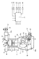
- FIG. 2 shows a system configuration of the internal combustion engine 1 including the variable compression ratio mechanism 2 and the variable valve timing mechanism 3.
- the internal combustion engine 1 is, for example, a 4-stroke cycle spark ignition internal combustion engine equipped with a variable compression ratio mechanism 2 using a multi-link type piston crank mechanism, and a pair of intake valves 32 are provided on a ceiling wall surface of each cylinder 31.
- a pair of exhaust valves 33 are arranged, and a spark plug 35 is arranged in a central portion surrounded by the intake valves 32 and the exhaust valves 33.
- the intake valve 32 includes a variable valve timing mechanism 3 capable of variably controlling the opening / closing timing of the intake valve 32.
- the variable valve timing mechanism 3 at least the closing timing may be delayed, but in the present embodiment, the opening timing and the closing timing are delayed at the same time by delaying the phase of the camshaft. Has become.
- Various types of such variable valve timing mechanisms are known, and the variable valve timing mechanism is not limited to a specific type of variable valve timing mechanism.
- variable valve timing mechanism 3 includes a sprocket that is concentrically arranged at the front end of the cam shaft, and a hydraulic rotary actuator that relatively rotates the sprocket and the cam shaft within a predetermined angle range. Is configured.
- the sprocket is interlocked with the crankshaft via a timing chain or timing belt (not shown). Therefore, the relative rotation between the sprocket and the cam shaft changes the phase of the cam shaft with respect to the crank angle.
- the actual control position of the cam shaft variably controlled by the variable valve timing mechanism 3 (which corresponds to the actual valve timing) is detected by the cam angle sensor 43 which responds to the rotational position of the cam shaft.
- the detection signal of the cam angle sensor 43 is input to the engine controller 11.
- the variable valve timing mechanism 3 is closed-loop controlled so that the actual control position detected by the cam angle sensor 43 matches the target control position set according to the operating conditions.
- a fuel injection valve 38 is arranged for each cylinder in an intake passage 37 connected to the combustion chamber 36 via the intake valve 32.
- a cylinder injection type configuration may be used in which fuel is directly injected into each cylinder 31.
- An electronically controlled throttle valve 39 whose opening is controlled by a control signal from the engine controller 11 is provided on the upstream side of the intake collector 37a in the intake passage 37.
- An air-fuel ratio sensor 41 for detecting an air-fuel ratio is arranged in the exhaust passage 40 connected to the combustion chamber 36 via the exhaust valve 33.
- a signal from the air-fuel ratio sensor 41, a signal from an air flow meter 42 that detects the intake air amount on the upstream side of the intake passage 37, and the like are also input to the engine controller 11. Has been done. Based on these detection signals, the engine controller 11 causes the fuel injection amount and injection timing of the fuel injection valve 38, the ignition timing of the spark plug 35, the mechanical compression ratio of the variable compression ratio mechanism 2, and the intake valve of the variable valve timing mechanism 3.
- the opening / closing timing of 32, the opening degree of the throttle valve 39, etc. are optimally controlled.
- the variable compression ratio mechanism 2 uses, for example, a well-known multi-link piston crank mechanism described in Patent Document 1 and the like, and includes a lower link 52 rotatably supported by a crank pin 51a of a crankshaft 51.
- An upper link 55 connecting the upper pin 53 at one end of the lower link 52 and the piston pin 54a of the piston 54 to each other, and a control link 57 having one end connected to a control pin 56 at the other end of the lower link 52,
- a control shaft 58 that swingably supports the other end of the control link 57 is mainly configured.
- the crankshaft 51 and the control shaft 58 are rotatably supported in a crankcase 59a below the cylinder block 59 via a bearing structure (not shown).
- the control shaft 58 has an eccentric shaft portion whose position changes in accordance with the rotation of the control shaft 58, and specifically, the end portion of the control link 57 is rotatably fitted to the eccentric shaft portion. ing.
- the top dead center position of the piston 54 is vertically displaced along with the rotation of the control shaft 58, so that the mechanical compression ratio changes.
- an electric actuator 61 having a rotation center axis parallel to the crankshaft 51 is arranged on the outer wall surface of the crankcase 59a.
- the electric actuator 61 is controlled via the first arm 62 fixed to the output rotary shaft of the electric actuator 61, the second arm 63 fixed to the control shaft 58, and the intermediate link 64 connecting the both.
- the shaft 58 is interlocked.
- the electric actuator 61 includes an electric motor and a speed change mechanism that are arranged in series in the axial direction.
- the actual value of the mechanical compression ratio variably controlled by the variable compression ratio mechanism 2 as described above, that is, the actual compression ratio is detected by the actual compression ratio detection sensor 66.
- the actual compression ratio detection sensor 66 is composed of, for example, a rotary potentiometer or a rotary encoder that detects the rotation angle of the control shaft 58 or the rotation angle of the output rotation shaft of the electric actuator 61.
- the actual compression ratio is obtained without using a separate sensor by obtaining the rotation amount of the electric motor from the command signal to the electric motor constituting the electric actuator 61 and obtaining the rotation angle of the control shaft 58 from the rotation amount. May be detected.
- the drive of the electric actuator 61 is controlled by the engine controller 11 so that the actual compression ratio obtained as described above becomes the target compression ratio corresponding to the operating condition.
- the engine controller 11 includes a target compression ratio map that uses the load (in other words, the required torque) of the internal combustion engine 1 and the rotation speed Ne as parameters as operating conditions, and sets the target compression ratio based on this map.
- FIG. 3 schematically shows the characteristics of the target compression ratio map.
- the target compression ratio is basically a high compression ratio on the low load side, and knocks as the load increases. The compression ratio is low due to suppression and the like.
- Sailing stop refers to opening the forward clutch 8 to disconnect the internal combustion engine 1 from the drive wheels 5 (that is, cutting off power transmission) during coasting due to the release of the accelerator pedal by the driver during travel, and internal combustion. This is a control for stopping the operation of the engine 1. By executing this sailing stop, the traveling distance of coasting travel becomes longer, which in turn reduces the fuel consumption rate.
- the following four conditions are satisfied at the same time (that is, an AND condition).
- Accelerator OFF that is, accelerator pedal opening APO is 0
- Brake off release of brake pedal
- Vehicle speed VSP is a predetermined sailing stop permission vehicle speed (for example, 50 km / h) or higher.
- Other sailing stop permission conditions cooling water temperature, lubricating oil temperature, air conditioner operating status, etc.
- the sailing stop ends when one of the following sailing stop cancellation conditions is satisfied (that is, the OR condition) after the start of the sailing stop. That is, the forward clutch 8 is engaged and the internal combustion engine 1 is restarted when the sailing stop release condition is satisfied.
- the vehicle speed is below a predetermined sailing stop release vehicle speed (for example, 40 km / h).
- Other sailing stop release conditions cooling water temperature, lubricating oil temperature, air conditioner operating status, etc.
- an inter-vehicle distance detecting device including a radar and a camera for detecting the distance to another vehicle traveling in front of the vehicle, “5. You can add "I have become” as one of the sailing stop cancellation conditions.
- the internal combustion engine 1 When the internal combustion engine 1 is restarted when the sailing stop is released, the internal combustion engine 1 tends to rotate when the forward clutch 8 is engaged because the vehicle is traveling, so the starter motor 10 is generally not driven. It can be restarted.
- the starter motor 10 may be supplementarily used to restart the engine.
- the vehicle of the above embodiment has an idle stop function that automatically stops the internal combustion engine 1 when the vehicle stops at an intersection or the like.
- various combinations are possible as conditions for performing the idle stop, basically, when the accelerator pedal opening APO is 0, the vehicle speed VSP is 0, and the brake pedal is depressed (the brake fluid pressure is a predetermined value). (When it is above the level), the operation of the internal combustion engine 1 is stopped because it is a temporary vehicle stop at an intersection or the like.
- Other conditions such as the shift position of the automatic transmission 4 and the cooling water temperature may be added as weighting conditions.
- the cranking by the starter motor 10 is performed when one of predetermined idle stop cancellation conditions such as release of the brake pedal, depression of the accelerator pedal, or a request from the air conditioner is satisfied. Accordingly, the internal combustion engine 1 is restarted.
- the target compression ratio of the variable compression ratio mechanism 2 is the target during normal operation shown in FIG.
- the predetermined sailing stop restart compression ratio ⁇ ss and the predetermined idle stop restart compression ratio ⁇ is are set independently of the compression ratio map. That is, at the time of sailing stop, the variable compression ratio mechanism 2 is controlled to a predetermined sailing stop restart compression ratio ⁇ ss for the restart when the sailing stop is released, and the restart when the sailing stop is released is performed for this sailing stop restart. It is performed under a compression ratio ⁇ ss.
- the variable compression ratio mechanism 2 is controlled to a predetermined idle stop restart compression ratio ⁇ is prepared for restarting when idle stop is released, and restarting when idle stop is released is performed by this idle stop restart compression ratio. performed under ⁇ is.
- the compression ratio for sailing stop restart ⁇ ss and the compression ratio for idle stop restart ⁇ is are individually set as different compression ratios even for the same automatic restart. Since the restart when the idle stop is released is a restart in the state where the vehicle is stopped, it is necessary to prevent a torque shock and a rapid increase in the rotation speed Ne (so-called upstroke) from occurring during the restart.
- the idle stop restart compression ratio ⁇ is is set to a compression ratio at which such a relatively gentle restart is achieved.
- the restart that accompanies the cancellation of the sailing stop during coasting is a restart in the presence of road noise and traveling vibration, and the acceleration response is not significant when the sailing stop is released by depressing the accelerator pedal. Required. Therefore, the sailing stop restart compression ratio ⁇ ss is set to a compression ratio that realizes a restart with a relatively excellent rise of torque.
- the idle stop / restart compression ratio ⁇ is set to a relatively high compression ratio suitable for low load operation. Therefore, a gentle start is realized with the minimum amount of fuel and the amount of intake air required for restarting.
- the sailing stop restart compression ratio ⁇ ss is set to a relatively low compression ratio suitable for high load operation. Therefore, it is possible to immediately shift to a high load operation upon completion of the restart, which is an excellent characteristic for the rise of torque.
- the sailing stop restart compression ratio ⁇ ss suitable for the above may be a relatively higher compression ratio than the idle stop restart compression ratio ⁇ is suitable for restart when the idle stop is released.
- FIG. 4 is a flowchart showing the control flow of the above sailing stop.
- the overall routine shown in this flowchart is executed by, for example, the engine controller 11, and a part of the processing is executed by the transmission controller 12.
- step 1 it is repeatedly determined whether or not the accelerator pedal opening APO has become 0 based on the detection signal of the accelerator opening sensor 15. If the accelerator pedal opening APO is not 0, the routine ends as it is.
- the target compression ratio of the variable compression ratio mechanism 2 is set using the target compression ratio map illustrated in FIG. 3 based on the load of the internal combustion engine 1 and the rotation speed Ne as described above.
- step 1 When it is determined in step 1 that the accelerator pedal opening APO is 0, the process proceeds to step 2 and it is determined whether or not the above-mentioned sailing stop start condition is satisfied. Here, if the sailing stop start condition is not satisfied, the routine proceeds to step 3 and shifts to idle stop control by another routine not shown.
- step 2 the process proceeds from step 2 to step 4, the sailing stop flag is turned on, and a request for sailing stop is output to the transmission controller 12.
- the transmission controller 12 releases the forward clutch 8 of the automatic transmission 4 in response to the sailing stop flag being turned on.
- the internal combustion engine 1 is separated from the CVT 9 and the drive wheels 5.
- step 4 the process proceeds from step 4 to step 5, and as the target compression ratio of the variable compression ratio mechanism 2, a relatively low compression ratio ⁇ ss for restarting the sailing stop is set, and the compression ratio ⁇ ss for restarting the sailing stop is set.
- the variable compression ratio mechanism 2 is driven along.
- step 6 it is determined whether or not the actual compression ratio detected by the actual compression ratio detection sensor 66 becomes the compression ratio for sailing stop restart ⁇ ss which is the target compression ratio, that is, the compression ratio change by the variable compression ratio mechanism 2. Determine whether it is complete.
- step 7 the operation of the internal combustion engine 1 is stopped.
- the compression ratio is changed by the variable compression ratio mechanism 2 before the operation of the internal combustion engine 1 is stopped.
- the oil pump for supplying the lubricating oil of the internal combustion engine 1 a mechanical oil pump driven by the crankshaft 51 of the internal combustion engine 1 is often used.
- the mechanical oil is stopped before the rotation of the internal combustion engine 1 is stopped.
- step 8 it is repeatedly determined whether or not the sailing stop cancellation condition is satisfied, for example, whether or not the accelerator pedal opening APO becomes larger than zero.
- the sailing stop continues until the conditions for canceling the sailing stop are met. If, for example, the accelerator pedal opening APO becomes larger than 0 as a sailing stop cancellation condition, the process proceeds from step 8 to step 9 to set the sailing stop flag to OFF and request the transmission controller 12 to cancel the sailing stop.
- the transmission controller 12 engages the forward clutch 8 in response to the sailing stop flag being turned off.
- step 10 the internal combustion engine 1 is restarted. Specifically, fuel injection and ignition are started.
- step 11 it is determined whether the restart of the internal combustion engine 1 is completed, that is, whether the internal combustion engine 1 is switched to the independent operation.
- the routine proceeds from step 11 to step 12 to restart the normal control of the internal combustion engine 1.
- the idle stop start condition that the accelerator pedal opening APO is 0, the vehicle speed VSP is 0, and the brake pedal is depressed is satisfied.
- the internal combustion engine 1 is automatically stopped as an idle stop.
- the target compression ratio of the variable compression ratio mechanism 2 is controlled to the idle stop restart compression ratio ⁇ is which is a relatively high compression ratio as described above. It is desirable to change the compression ratio to the idle stop restart compression ratio ⁇ is before the internal combustion engine 1 is stopped.
- an idle stop release condition such as release of the brake pedal is satisfied during idle stop, the internal combustion engine 1 is restarted with cranking by the starter motor 10.
- the lockup clutch 6 of the torque converter 7 is released.
- FIG. 5 is a time chart showing the operation during the idle stop control.
- IVC intake valve closing timing
- VSP accelerator pedal opening APO
- VSP vehicle speed VSP
- target compression ratio actual compression ratio is substantially in line with this
- Ne rotational speed Ne of the internal combustion engine 1
- torque of the internal combustion engine 1 The control state of the lockup clutch 6 of the torque converter 7 is shown.
- the accelerator pedal opening APO becomes 0, and the vehicle speed VSP gradually decreases.
- the vehicle speed VSP becomes 0 (that is, the vehicle is stopped), and the idle stop flag is turned on.
- the lockup clutch 6 is released immediately before the vehicle stops.
- the target compression ratio of the variable compression ratio mechanism 2 during idle stop is set to the idle stop restart compression ratio ⁇ is, which is a relatively high compression ratio, and the actual compression ratio is changed before the operation of the internal combustion engine 1 is stopped. Is done.
- the target compression ratio is a high compression ratio because the load is low even before time t1, and in the illustrated example, there is almost no change in the compression ratio before and after time t1.
- the idle stop flag is turned off and the internal combustion engine 1 is restarted.
- the target compression ratio of the variable compression ratio mechanism 2 changes to the target compression ratio according to the load and the rotation speed Ne.
- the control of the intake valve closing timing (IVC) by the variable valve timing mechanism 3 is not a main part of the present invention, but in the illustrated example, the intake valve closing timing (IVC) is kept at the most retarded position during idle stop. ing.
- the variable valve timing mechanism 3 generally includes a lock mechanism that mechanically locks at the most retarded angle position, and when the internal combustion engine 1 is stopped, the variable valve timing mechanism 3 is locked at the most retarded angle position. .. Therefore, the internal combustion engine 1 is restarted at the time t2 with the intake valve closing timing being in the most retarded position.
- the compression ratio by the variable compression ratio mechanism 2 is controlled to the idle stop restart compression ratio ⁇ is, which is a relatively high compression ratio. Therefore, a gentle start is realized by the minimum fuel amount and intake amount required for restart. Therefore, the start / start is performed while suppressing the torque step and the rising of the rotation speed Ne.
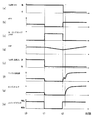
- FIG. 6 is a time chart showing the operation during the sailing stop control.
- IVC intake valve closing timing
- VSP accelerator pedal opening APO
- sailing stop flag a vehicle speed VSP
- target compression ratio actual compression ratio is substantially in line with this
- Ne rotational speed Ne of the internal combustion engine 1
- g torque of the internal combustion engine 1
- h torque of the internal combustion engine 1
- the control state of the forward clutch 8 of the automatic transmission 4 is shown.
- the driver depresses the accelerator pedal to satisfy the sailing stop release condition, the sailing stop flag is turned off, and the forward clutch 8 is engaged.
- fuel supply and ignition of the internal combustion engine 1 are restarted, and the internal combustion engine 1 is restarted.
- the target compression ratio of the variable compression ratio mechanism 2 changes to the target compression ratio according to the load and the rotation speed Ne.
- the accelerator pedal opening APO is relatively large, the compression ratio is relatively low, which is similar to the sailing stop restart compression ratio ⁇ ss.
- the intake valve closing timing (IVC) by the variable valve timing mechanism 3 is the same as during idle stop, and is held at the most retarded position by the lock mechanism during sailing stop. Therefore, the restart at the time t2 is performed in the state where the intake valve closing timing is at the most retarded position.
- the accelerator pedal opening APO increases after time t2, the lock at the most retarded position is released, and the intake valve closing timing is controlled according to the operating conditions (load and rotation speed Ne).
- the compression ratio by the variable compression ratio mechanism 2 is controlled to the sailing stop restart compression ratio ⁇ ss, which is a relatively low compression ratio. Therefore, it is possible to immediately shift to high load operation upon completion of the restart, and the characteristic is excellent in the rise of torque. Therefore, the acceleration responsiveness to the depression of the accelerator pedal by the driver is improved.
- the sailing stop restart compression ratio ⁇ ss which is the target compression ratio of the variable compression ratio mechanism 2
- the compression ratio ⁇ ss for restarting the sailing stop is variably given according to the vehicle speed VSP at that time.
- the sailing stop restart compression ratio ⁇ ss is set as a lower compression ratio as the vehicle speed VSP increases.
- the characteristic may be such that the compression ratio changes continuously with respect to the vehicle speed VSP, or may change stepwise.
- variable compression ratio mechanism 2 can change the compression ratio even when the internal combustion engine 1 is stopped.
- the sailing stop restart compression ratio ⁇ ss is set according to the vehicle speed VSP, when the sailing stop is released and the internal combustion engine 1 is restarted, the vehicle speed VSP at that time and thus the rotation speed Ne of the internal combustion engine 1 are set.
- the compression ratio corresponds to. Therefore, the restart is performed under a more appropriate compression ratio.
- the sailing stop restart compression ratio ⁇ ss is a low compression ratio, so that a high load operation is performed immediately upon completion of the restart. It is possible to shift to, and a good acceleration response in line with the driver's intention can be obtained.
- the sailing stop restart compression ratio ⁇ ss is suitable for low load operation. Because of the high compression ratio, a gentle restart is realized as well as a restart from idle stop.
Landscapes
- Engineering & Computer Science (AREA)
- Chemical & Material Sciences (AREA)
- Combustion & Propulsion (AREA)
- Mechanical Engineering (AREA)
- General Engineering & Computer Science (AREA)
- Transportation (AREA)
- Ocean & Marine Engineering (AREA)
- Automation & Control Theory (AREA)
- Output Control And Ontrol Of Special Type Engine (AREA)
- Control Of Vehicle Engines Or Engines For Specific Uses (AREA)
- Control Of Driving Devices And Active Controlling Of Vehicle (AREA)
Abstract
Description
2.ブレーキOFF(ブレーキペダルの解放)
3.車速VSPが所定のセーリングストップ許可車速(例えば50km/h)以上
4.他のセーリングストップ許可条件(冷却水温、潤滑油温、空調装置の稼動状態、等)
セーリングストップは、セーリングストップ開始後、下記のセーリングストップ解除条件のいずれかが成立(つまりOR条件)したときに終了する。つまり、セーリングストップ解除条件の成立によって、フォワードクラッチ8が締結されるとともに、内燃機関1が再始動される。
2.アクセルON(アクセルペダル開度APOが0よりも大)
3.車速が所定のセーリングストップ解除車速(例えば40km/h)以下
4.他のセーリングストップ解除条件(冷却水温、潤滑油温、空調装置の稼動状態、等)
車両が車両前方を走行する他の車両との距離を検出するレーダやカメラ等からなる車間距離検出装置を具備する場合には、「5.前方車両との間の車間距離が所定の距離以下となったこと」をセーリングストップ解除条件の1つとして加えてもよい。
Claims (5)
- 機械的圧縮比を変更可能な可変圧縮比機構を備えた内燃機関の制御方法において、
内燃機関の運転中は内燃機関の運転条件に基づいて設定される基本目標圧縮比を目標圧縮比とし、
車両の停止に伴い内燃機関の運転を停止するアイドルストップ時は、アイドルストップ解除に伴う再始動に備えたアイドルストップ再始動用圧縮比を目標圧縮比とし、
車両の惰行走行中に内燃機関を駆動系から切り離すとともに内燃機関の運転を停止するセーリングストップ時は、セーリングストップ解除に伴う再始動に備えた、上記アイドルストップ再始動用圧縮比とは異なる、セーリングストップ再始動用圧縮比を目標圧縮比とする、内燃機関の制御方法。 - セーリングストップの条件成立時に、内燃機関の停止に先だって、上記可変圧縮比機構により機械的圧縮比を上記セーリングストップ再始動用圧縮比へと変更する、請求項1に記載の内燃機関の制御方法。
- 上記セーリングストップ再始動用圧縮比は上記アイドルストップ再始動用圧縮比よりも相対的に低い圧縮比である、請求項1または2に記載の内燃機関の制御方法。
- 上記セーリングストップ再始動用圧縮比を、セーリングストップ中の車速が高いほど低い圧縮比として設定する、請求項1~3のいずれかに記載の内燃機関の制御方法。
- 機械的圧縮比を変更可能な可変圧縮比機構を備えた内燃機関の制御装置において、
内燃機関の運転条件に基づいて基本目標圧縮比を設定する基本目標圧縮比設定部と、
所定の車両停止時に内燃機関の運転を停止するアイドルストップを実行するアイドルストップ制御部と、
所定の惰行走行中に内燃機関を駆動系から切り離すとともに内燃機関の運転を停止するセーリングストップを実行するセーリングストップ制御部と、
内燃機関の運転中は上記基本目標圧縮比を目標圧縮比とし、アイドルストップ時はアイドルストップ再始動用圧縮比を目標圧縮比とし、セーリングストップ時は、アイドルストップ再始動用圧縮比とは異なるセーリングストップ再始動用圧縮比を目標圧縮比として、上記可変圧縮比機構を制御する圧縮比制御部と、
を備えてなる内燃機関の制御装置。
Priority Applications (5)
| Application Number | Priority Date | Filing Date | Title |
|---|---|---|---|
| JP2020556348A JP7425742B2 (ja) | 2018-11-06 | 2018-11-06 | 内燃機関の制御方法および制御装置 |
| CN201880099078.XA CN113227560B (zh) | 2018-11-06 | 2018-11-06 | 内燃机的控制方法及控制装置 |
| EP18939131.1A EP3879090B1 (en) | 2018-11-06 | 2018-11-06 | Control method and control device for internal combustion engine |
| US17/291,377 US11713726B2 (en) | 2018-11-06 | 2018-11-06 | Control method and control device for internal combustion engine |
| PCT/IB2018/001331 WO2020095081A1 (ja) | 2018-11-06 | 2018-11-06 | 内燃機関の制御方法および制御装置 |
Applications Claiming Priority (1)
| Application Number | Priority Date | Filing Date | Title |
|---|---|---|---|
| PCT/IB2018/001331 WO2020095081A1 (ja) | 2018-11-06 | 2018-11-06 | 内燃機関の制御方法および制御装置 |
Publications (1)
| Publication Number | Publication Date |
|---|---|
| WO2020095081A1 true WO2020095081A1 (ja) | 2020-05-14 |
Family
ID=70611136
Family Applications (1)
| Application Number | Title | Priority Date | Filing Date |
|---|---|---|---|
| PCT/IB2018/001331 Ceased WO2020095081A1 (ja) | 2018-11-06 | 2018-11-06 | 内燃機関の制御方法および制御装置 |
Country Status (5)
| Country | Link |
|---|---|
| US (1) | US11713726B2 (ja) |
| EP (1) | EP3879090B1 (ja) |
| JP (1) | JP7425742B2 (ja) |
| CN (1) | CN113227560B (ja) |
| WO (1) | WO2020095081A1 (ja) |
Cited By (1)
| Publication number | Priority date | Publication date | Assignee | Title |
|---|---|---|---|---|
| CN113864068A (zh) * | 2020-06-30 | 2021-12-31 | 通用汽车环球科技运作有限责任公司 | 可变压缩比发动机控制策略 |
Families Citing this family (2)
| Publication number | Priority date | Publication date | Assignee | Title |
|---|---|---|---|---|
| JP6801627B2 (ja) * | 2017-10-25 | 2020-12-16 | トヨタ自動車株式会社 | 車両 |
| KR102804907B1 (ko) * | 2019-09-20 | 2025-05-09 | 현대자동차 주식회사 | 타행 주행 기능 및 isg 기능 제어 방법 및 그 방법이 적용된 차량 |
Citations (6)
| Publication number | Priority date | Publication date | Assignee | Title |
|---|---|---|---|---|
| JP2004293411A (ja) * | 2003-03-27 | 2004-10-21 | Toyota Motor Corp | 圧縮比を変更可能な内燃機関とその制御方法 |
| JP2008111375A (ja) * | 2006-10-30 | 2008-05-15 | Nissan Motor Co Ltd | エンジンの圧縮比制御装置及び圧縮比制御方法 |
| JP2012225165A (ja) * | 2011-04-15 | 2012-11-15 | Nissan Motor Co Ltd | 可変圧縮比エンジンの制御装置 |
| JP2014196665A (ja) * | 2013-03-29 | 2014-10-16 | 日立オートモティブシステムズ株式会社 | 内燃機関の制御装置 |
| WO2016194605A1 (ja) * | 2015-06-03 | 2016-12-08 | 日立オートモティブシステムズ株式会社 | 車両用エンジン始動装置 |
| JP2017008876A (ja) | 2015-06-25 | 2017-01-12 | 日産自動車株式会社 | 車両の制御装置 |
Family Cites Families (14)
| Publication number | Priority date | Publication date | Assignee | Title |
|---|---|---|---|---|
| JP4941281B2 (ja) * | 2007-12-26 | 2012-05-30 | 日産自動車株式会社 | ハイブリッド車両の制御装置及び制御方法 |
| DE102010032488A1 (de) * | 2010-07-28 | 2012-02-02 | Daimler Ag | Verfahren zum Betreiben einer Hubkolbenmaschine |
| EP2775122B1 (en) * | 2011-11-01 | 2019-10-23 | Nissan Motor Company, Limited | Internal-combustion engine control device and control method |
| JP5652573B2 (ja) * | 2012-05-17 | 2015-01-14 | 日産自動車株式会社 | 内燃機関の制御装置及び制御方法 |
| US9617926B2 (en) * | 2013-12-25 | 2017-04-11 | Nissan Motor Co., Ltd. | Device and method for controlling internal combustion engine for vehicle |
| JP6326934B2 (ja) * | 2014-04-21 | 2018-05-23 | 三菱自動車工業株式会社 | エンジンの制御装置 |
| DE112015003480A5 (de) * | 2014-07-29 | 2017-06-14 | FEV Europe GmbH | Verfahren zum Betreiben einer Verbrennungskraftmaschine mit einem einstellbaren Neustartverdichtungsverhältnis |
| JP2016113947A (ja) | 2014-12-15 | 2016-06-23 | 日立オートモティブシステムズ株式会社 | 車両用制御装置 |
| JP6252495B2 (ja) * | 2015-01-07 | 2017-12-27 | トヨタ自動車株式会社 | 車両の制御装置 |
| JP6734633B2 (ja) * | 2015-07-06 | 2020-08-05 | 日産自動車株式会社 | 内燃機関の制御装置 |
| JP6528604B2 (ja) * | 2015-08-26 | 2019-06-12 | 日産自動車株式会社 | 可変圧縮比機構を備えた内燃機関の制御方法及び制御装置 |
| JP6587977B2 (ja) | 2016-05-25 | 2019-10-09 | 日立オートモティブシステムズ株式会社 | エンジンの制御装置 |
| JP2018091392A (ja) * | 2016-12-02 | 2018-06-14 | ジヤトコ株式会社 | 車両のセーリングストップ制御装置及び制御方法 |
| JP2018178919A (ja) * | 2017-04-18 | 2018-11-15 | トヨタ自動車株式会社 | 車両の制御装置 |
-
2018
- 2018-11-06 JP JP2020556348A patent/JP7425742B2/ja active Active
- 2018-11-06 CN CN201880099078.XA patent/CN113227560B/zh active Active
- 2018-11-06 WO PCT/IB2018/001331 patent/WO2020095081A1/ja not_active Ceased
- 2018-11-06 EP EP18939131.1A patent/EP3879090B1/en active Active
- 2018-11-06 US US17/291,377 patent/US11713726B2/en active Active
Patent Citations (6)
| Publication number | Priority date | Publication date | Assignee | Title |
|---|---|---|---|---|
| JP2004293411A (ja) * | 2003-03-27 | 2004-10-21 | Toyota Motor Corp | 圧縮比を変更可能な内燃機関とその制御方法 |
| JP2008111375A (ja) * | 2006-10-30 | 2008-05-15 | Nissan Motor Co Ltd | エンジンの圧縮比制御装置及び圧縮比制御方法 |
| JP2012225165A (ja) * | 2011-04-15 | 2012-11-15 | Nissan Motor Co Ltd | 可変圧縮比エンジンの制御装置 |
| JP2014196665A (ja) * | 2013-03-29 | 2014-10-16 | 日立オートモティブシステムズ株式会社 | 内燃機関の制御装置 |
| WO2016194605A1 (ja) * | 2015-06-03 | 2016-12-08 | 日立オートモティブシステムズ株式会社 | 車両用エンジン始動装置 |
| JP2017008876A (ja) | 2015-06-25 | 2017-01-12 | 日産自動車株式会社 | 車両の制御装置 |
Non-Patent Citations (1)
| Title |
|---|
| See also references of EP3879090A4 |
Cited By (2)
| Publication number | Priority date | Publication date | Assignee | Title |
|---|---|---|---|---|
| CN113864068A (zh) * | 2020-06-30 | 2021-12-31 | 通用汽车环球科技运作有限责任公司 | 可变压缩比发动机控制策略 |
| CN113864068B (zh) * | 2020-06-30 | 2024-04-16 | 通用汽车环球科技运作有限责任公司 | 可变压缩比发动机控制策略 |
Also Published As
| Publication number | Publication date |
|---|---|
| CN113227560B (zh) | 2023-08-01 |
| EP3879090A1 (en) | 2021-09-15 |
| EP3879090B1 (en) | 2025-10-08 |
| EP3879090A4 (en) | 2021-11-17 |
| US11713726B2 (en) | 2023-08-01 |
| CN113227560A (zh) | 2021-08-06 |
| JP7425742B2 (ja) | 2024-01-31 |
| JPWO2020095081A1 (ja) | 2021-10-14 |
| US20220003175A1 (en) | 2022-01-06 |
Similar Documents
| Publication | Publication Date | Title |
|---|---|---|
| EP2772397B1 (en) | Hybrid vehicle control apparatus | |
| US8827866B2 (en) | Vehicle and control method | |
| CN103717464B (zh) | 混合动力车辆的发动机停止控制装置 | |
| JP6179563B2 (ja) | 車両の制御装置 | |
| US8495981B2 (en) | System and method for cam phaser control in an engine | |
| JP5907280B2 (ja) | 車両の走行制御装置 | |
| US20150175155A1 (en) | Vehicle and control method | |
| CN106335492B (zh) | 车辆的控制装置 | |
| JP7425742B2 (ja) | 内燃機関の制御方法および制御装置 | |
| WO2006030707A1 (ja) | 車両の制御装置 | |
| JP3678095B2 (ja) | 内燃機関の制御装置 | |
| JP4147398B2 (ja) | エンジン制御装置 | |
| JP6515710B2 (ja) | 内燃機関の制御装置 | |
| JP2937034B2 (ja) | 作動気筒数可変内燃機関を有する車両の運転制御装置 | |
| JP4720581B2 (ja) | エンジンの始動装置 | |
| JP4702143B2 (ja) | エンジンの始動装置 | |
| JP2010229911A (ja) | 可変動弁機構の制御装置 | |
| JP6443244B2 (ja) | 可変圧縮比内燃機関の制御装置 | |
| JP3610752B2 (ja) | 車両用出力制御装置 | |
| WO2014167725A1 (ja) | 車両の制御装置 | |
| JP2017019350A (ja) | 車両の走行制御装置 |
Legal Events
| Date | Code | Title | Description |
|---|---|---|---|
| 121 | Ep: the epo has been informed by wipo that ep was designated in this application |
Ref document number: 18939131 Country of ref document: EP Kind code of ref document: A1 |
|
| ENP | Entry into the national phase |
Ref document number: 2020556348 Country of ref document: JP Kind code of ref document: A |
|
| NENP | Non-entry into the national phase |
Ref country code: DE |
|
| ENP | Entry into the national phase |
Ref document number: 2018939131 Country of ref document: EP Effective date: 20210607 |
|
| WWG | Wipo information: grant in national office |
Ref document number: 2018939131 Country of ref document: EP |