WO2020100675A1 - Rotor et machine électrique rotative équipée de celui-ci - Google Patents
Rotor et machine électrique rotative équipée de celui-ci Download PDFInfo
- Publication number
- WO2020100675A1 WO2020100675A1 PCT/JP2019/043394 JP2019043394W WO2020100675A1 WO 2020100675 A1 WO2020100675 A1 WO 2020100675A1 JP 2019043394 W JP2019043394 W JP 2019043394W WO 2020100675 A1 WO2020100675 A1 WO 2020100675A1
- Authority
- WO
- WIPO (PCT)
- Prior art keywords
- rib
- magnetic pole
- center line
- rotor
- ribs
- Prior art date
- Legal status (The legal status is an assumption and is not a legal conclusion. Google has not performed a legal analysis and makes no representation as to the accuracy of the status listed.)
- Ceased
Links
Images


Classifications
-
- H—ELECTRICITY
- H02—GENERATION; CONVERSION OR DISTRIBUTION OF ELECTRIC POWER
- H02K—DYNAMO-ELECTRIC MACHINES
- H02K1/00—Details of the magnetic circuit
- H02K1/06—Details of the magnetic circuit characterised by the shape, form or construction
- H02K1/22—Rotating parts of the magnetic circuit
- H02K1/27—Rotor cores with permanent magnets
- H02K1/2706—Inner rotors
- H02K1/272—Inner rotors the magnetisation axis of the magnets being perpendicular to the rotor axis
- H02K1/274—Inner rotors the magnetisation axis of the magnets being perpendicular to the rotor axis the rotor consisting of two or more circumferentially positioned magnets
- H02K1/2753—Inner rotors the magnetisation axis of the magnets being perpendicular to the rotor axis the rotor consisting of two or more circumferentially positioned magnets the rotor consisting of magnets or groups of magnets arranged with alternating polarity
- H02K1/276—Magnets embedded in the magnetic core, e.g. interior permanent magnets [IPM]
- H02K1/2766—Magnets embedded in the magnetic core, e.g. interior permanent magnets [IPM] having a flux concentration effect
-
- H—ELECTRICITY
- H02—GENERATION; CONVERSION OR DISTRIBUTION OF ELECTRIC POWER
- H02K—DYNAMO-ELECTRIC MACHINES
- H02K1/00—Details of the magnetic circuit
- H02K1/06—Details of the magnetic circuit characterised by the shape, form or construction
- H02K1/22—Rotating parts of the magnetic circuit
- H02K1/27—Rotor cores with permanent magnets
- H02K1/2706—Inner rotors
- H02K1/272—Inner rotors the magnetisation axis of the magnets being perpendicular to the rotor axis
- H02K1/274—Inner rotors the magnetisation axis of the magnets being perpendicular to the rotor axis the rotor consisting of two or more circumferentially positioned magnets
- H02K1/2753—Inner rotors the magnetisation axis of the magnets being perpendicular to the rotor axis the rotor consisting of two or more circumferentially positioned magnets the rotor consisting of magnets or groups of magnets arranged with alternating polarity
- H02K1/276—Magnets embedded in the magnetic core, e.g. interior permanent magnets [IPM]
-
- H—ELECTRICITY
- H02—GENERATION; CONVERSION OR DISTRIBUTION OF ELECTRIC POWER
- H02K—DYNAMO-ELECTRIC MACHINES
- H02K21/00—Synchronous motors having permanent magnets; Synchronous generators having permanent magnets
- H02K21/12—Synchronous motors having permanent magnets; Synchronous generators having permanent magnets with stationary armatures and rotating magnets
- H02K21/14—Synchronous motors having permanent magnets; Synchronous generators having permanent magnets with stationary armatures and rotating magnets with magnets rotating within the armatures
-
- H—ELECTRICITY
- H02—GENERATION; CONVERSION OR DISTRIBUTION OF ELECTRIC POWER
- H02K—DYNAMO-ELECTRIC MACHINES
- H02K2213/00—Specific aspects, not otherwise provided for and not covered by codes H02K2201/00 - H02K2211/00
- H02K2213/03—Machines characterised by numerical values, ranges, mathematical expressions or similar information
Definitions
- the present disclosure relates to a rotor and a rotating electric machine including the rotor.
- a rotor including a core portion in which a through hole group including a plurality of through holes is formed is known (for example, Patent Document 1).
- the core portion of the rotor of the document has ribs located between the through holes, and the widths of the ribs are substantially equal to each other.
- the purpose of the present disclosure is to optimize the size of the ribs of the rotor.
- a first aspect of the present disclosure is a rotor including a core portion (21) in which a through hole group (100) including three or more through holes (25) arranged in the circumferential direction is formed in a predetermined magnetic pole (21). 20) is targeted.
- the rotor (20) is provided in the core portion (21) and includes two or more ribs (24) located between the through holes (25), and the center of the magnetic pole in the circumferential direction and the center of the magnetic pole in the circumferential direction.
- the rib (24) having a relatively small inclination ( ⁇ ) with respect to the magnetic pole center line (MC) is defined by a straight line passing through the shaft center (O) of the rotor (20).
- the width is narrower than that of the rib (24) having a relatively large inclination ( ⁇ ) with respect to the magnetic pole center line (MC).
- the inventor of the present application has found that, in a given magnetic pole, the centrifugal force acting on the radially outer portion of the through hole group (100) is substantially parallel to the magnetic pole center line (MC), and the rib (24) in the magnetic pole. And that as the inclination ( ⁇ ) of the rib (24) with respect to the magnetic pole center line becomes smaller, the bending force acting on the rib (24) due to the centrifugal force becomes smaller. It was Further, the inventor of the present application has found that the smaller the force in the bending direction acting on the rib (24), the less the problem of strength design even if the rib (24) is designed to be narrow.
- the rib (24) having a relatively small inclination ( ⁇ ) with respect to the magnetic pole center line (MC) has a relatively small inclination ( ⁇ ) with respect to the magnetic pole center line (MC).
- ⁇ inclination
- MC magnetic pole center line
- the “inclination” of the rib (24) with respect to the magnetic pole center line (MC) means the center line (CL) of the rib (24) (that is, the rib (24) as shown in FIG. ) Means the angle ( ⁇ ) formed between the magnetic pole center line (MC) and the straight line passing through the middle of the two through holes (25) adjacent to each other.
- the “width” of the rib (24) means the shortest length (W) of the rib (24). More specifically, the “width” of the rib (24) is, as shown in FIG.
- a straight center line (CL ) May be the shortest length (W) of the rib (24).
- a distance (L) from the magnetic pole center line (MC) in the circumferential direction is relatively small.
- the neighboring rib (24-1) includes a rib (24-1) and a spacing rib (24-2, 24-3) having a relatively large distance (L) from the magnetic pole center line (MC) in the circumferential direction.
- the inclination ( ⁇ 1) of (-1) with respect to the magnetic pole center line (MC) is smaller than the inclination ( ⁇ 2, ⁇ 3) of the separation ribs (24-2, 24-3) with respect to the magnetic pole center line (MC),
- the neighboring rib (24-1) is characterized in that it is narrower than the spacing ribs (24-2, 24-3).
- the neighboring rib (24-1) having a relatively small inclination ( ⁇ 1) with respect to the magnetic pole center line (MC) has a relatively large inclination ( ⁇ 2, ⁇ 3) with respect to the magnetic pole center line (MC). It is designed to be narrower than the large spacing ribs (24-2, 24-3).
- the neighboring ribs (24-1), which have a relatively small bending-direction force acting due to the centrifugal force have similar spacing-direction bending ribs (24-2, 24). -3) is designed to be narrower than.
- the “distance” from the magnetic pole center line (ML) in the circumferential direction means the center of the rib (24) in the longitudinal and width directions from the magnetic pole center line (ML) as shown in FIG. Means the circumferential distance (L) to.
- a portion of the through hole (25) adjacent to the rib (24) is a rib adjacent portion (25a), and the through hole (25).
- a rib chamfer is formed on the rib adjacent portion (25a), and the rib adjacent portion (25a) adjacent to the rib (24) has a relatively small inclination ( ⁇ ) with respect to the magnetic pole center line (MC).
- the R chamfer dimension (R) is the R chamfer dimension (R) of the rib adjacent portion (25a) adjacent to the rib (24) having a relatively large inclination ( ⁇ ) with respect to the magnetic pole center line (MC). It is characterized by being smaller than R).
- the rib (24) having a relatively small inclination ( ⁇ ) with respect to the magnetic pole center line (MC) is compared with the rib (24) having a relatively large inclination ( ⁇ ) with respect to the magnetic pole center line (MC).
- it is designed to be narrow over a wide range in the longitudinal direction, which is the direction along the center line (CL). This is because, of the ribs (24), the portion adjacent to the portion of the rib adjacent portion (25a) where the R chamfer is formed is wider than the other portions, whereas the former rib (24) is different from the latter rib (24). This is because the wider range becomes smaller than that in 24).
- the size of the former rib (24) on which a relatively small force in the bending direction acts can be further optimized.
- R chamfer means that the intersecting surface portion is rounded.
- the through hole group (100) includes four or more holes arranged substantially symmetrically with respect to the magnetic pole center line (MC).
- Two or more ribs (24) each including an even number of through holes (25) include a central rib (24-1) located on the magnetic pole center line (MC).
- the mass point of the radially outer portion of the through hole group (100) is located on the center line (CL) of the center rib (24-1) (that is, on the magnetic pole center line (MC)). .. Therefore, the force in the bending direction that acts on the central rib (24-1) due to the centrifugal force that acts on the mass point is extremely small. As a result, the width of the center rib (24-1) can be narrowed as compared with the case where the center rib (24-1) is provided at a position other than on the magnetic pole center line (MC). It is possible to suppress magnetic flux leakage (that is, generation of magnetic flux that does not contribute to torque generation) via 1).
- substantially symmetric means not only strictly symmetrical with respect to the magnetic pole center line (MC) but also slightly asymmetrical with respect to the magnetic pole center line (MC) due to manufacturing error. It is meant to include some cases.
- a fifth aspect of the present disclosure is the first aspect, wherein the two or more ribs (24) are parallel ribs (24-1) extending substantially parallel to the magnetic pole center line (MC).
- the parallel ribs (24-1) include the inclined ribs (24-2, 24-3) extending obliquely with respect to the magnetic pole center line (MC), and the parallel ribs (24-1) have the inclined ribs (24-2, 24-3). It is characterized by being narrower than -3).
- the inclination ( ⁇ 1) with respect to the magnetic pole center line (MC) is relatively small, and the parallel rib (24-1) having a very small inclination ( ⁇ 2, ⁇ 3) with respect to the magnetic pole center line (MC).
- substantially parallel means that the angle ( ⁇ ) formed by the magnetic pole center line (MC) and the center line (CL) of the rib (24) is less than 5 °.
- “Inclined” means that the angle ( ⁇ ) formed by the magnetic pole center line (MC) and the center line (CL) of the rib (24) is 5 ° or more.
- the direction in which the rib (24) “extends” means the direction in which the center line (CL) of the rib (24) extends.
- a sixth aspect of the present disclosure is the method according to any one of the first to fifth aspects, wherein a permanent magnet (26) is arranged in a part or all of the three or more through holes (25). It is characterized by being
- the magnetic flux of the permanent magnet (26) can be efficiently used. This is because the width dimension of the rib (24) is designed to be the minimum dimension required for strength design, and this causes the magnetic flux of the permanent magnet (26) to short-circuit in the rotor (20) via the rib (24). This is because it has become difficult.
- the seventh aspect of the present disclosure is directed to the rotating electric machine (1).
- This rotary electric machine (1) includes a rotor (20) according to any one of the first to sixth aspects, and a stator (10) provided outside the rotor (20) in the radial direction. ..
- the rotary electric machine (1) is an inner rotor type rotary electric machine. Since the ribs (24) of the rotor (20) included in the rotary electric machine (1) are designed to have necessary and sufficient dimensions in terms of strength design, high-speed rotation (for example, 10,000 to 15,000 rpm or more) ), The rotor (20) is less likely to be damaged due to centrifugal force.
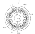
- FIG. 1 is a plan view showing the electric motor of the embodiment.
- FIG. 2 is a plan view showing a core member that constitutes the rotor.
- FIG. 3 is a partial plan view showing a through hole group corresponding to one magnetic pole in the rotor.
- FIG. 4 is a partial plan view showing a through hole group corresponding to one magnetic pole in a rotor of another embodiment.
- FIG. 5 is a schematic diagram for explaining dimensions and the like related to the through holes and the ribs.
- the electric motor (1) of the present embodiment is an example of a rotary electric machine, and is configured as an embedded magnet type electric motor.
- the configuration of the electric motor (1) will be described below.
- the electric motor (1) includes a stator (10), a rotor (20), and a drive shaft (30).
- the axial direction means the direction of the axis of the drive shaft (30)
- the radial direction means the direction orthogonal to the axial direction.
- the outer peripheral side means the side away from the axis, and the inner peripheral side means the side close to the axis.
- the stator (10) includes a cylindrical stator core (11) and a coil (not shown).
- the stator core (11) is configured by stacking a plurality of plate-shaped members formed by punching electromagnetic steel plates with a press machine in the axial direction. That is, the stator core (11) is a so-called laminated core.
- the stator core (11) may be composed of, for example, a dust core.
- the stator core (11) includes one back yoke part (12), a plurality of teeth (13), and the same number of brim parts (14) as the teeth (13).
- the back yoke part (12) is an annular part on the outer peripheral side of the stator core (11) in plan view.
- Each tooth (13) is a rectangular parallelepiped portion that extends in the radial direction in the stator core (11).
- the coil is wound around each tooth (13) by, for example, a distributed winding method.
- the space between the teeth (13) adjacent to each other functions as a coil slot (15) for housing the coil.
- the electromagnet is formed in each tooth (13).
- the coil may be wound around the tooth (13) by a concentrated winding method.
- the brim part (14) is a part that continuously extends to the inner peripheral side of each tooth (13) on both sides. Therefore, the flange portion (14) is formed to have a width (circumferential length) larger than that of the tooth (13).
- the flange portion (14) has a cylindrical surface on the inner peripheral side, and the cylindrical surface faces the outer peripheral surface (cylindrical surface) of the rotor (20) with a predetermined distance (air gap).
- the rotor (20) includes a rotor core (21) and a plurality of permanent magnets (26). In the rotor (20), these permanent magnets (26) form eight magnetic poles. All of these permanent magnets (26) have the same shape. These permanent magnets (26) are composed of, for example, sintered magnets.
- the permanent magnet (26) of this example is a so-called rare earth magnet using a rare earth element.
- the permanent magnet (26) penetrates the rotor core (21) in the axial direction.
- the rotor core (21) constitutes a core part.
- the rotor core (21) is a cylinder formed by stacking a large number of core members (22) in the axial direction by punching electromagnetic steel sheets with a thickness of 0.1 to 0.5 mm by a press machine. It is configured in a shape. That is, the rotor core (21) is a so-called laminated core.
- the rotor core (21) may be made of, for example, a high-strength electromagnetic steel plate, a silicon steel plate with a silicon content of 6.5%, or a dust core.
- the rotor core (21) has a shaft hole (23) formed in the center.
- a drive shaft (30) for driving a load (for example, a rotary compressor of an air conditioner) is fixed to the shaft hole (23) by interference fitting (for example, shrink fitting). Therefore, the axis (O) of the rotor core (21) (that is, the axis (O) of the rotor (20)) and the axis of the drive shaft (30) are coaxial with each other.
- each through hole (25) is determined so that a gap can be formed if necessary when the permanent magnet (26) is inserted.
- a through hole group (100) including a plurality of through holes (25) arranged in the circumferential direction for each magnetic pole is provided in the radial direction in a multilayer ( In the example, two layers are formed.
- the through hole group (100) of each layer is arranged along an arcuate region that is convex toward the axis (O) of the rotor (20).
- a branch number is added to the end of the reference numeral (for example, 25-1, 25-2, 100-1 etc.).
- one magnetic pole has two through hole groups (100).
- the through hole group (100-2) of the outer peripheral layer is formed by two through holes (25-5, 25-6).
- the through hole group (100-1) of the inner layer is formed by four through holes (25-1, 25-2, 25-3, 25-4).
- the four through holes (25-1, 25-2, 25-3, 25-4) forming the through hole group (100-1) of the inner peripheral layer are formed by the center of the magnetic pole in the circumferential direction and the rotor ( A straight line passing through the axis (O) of 20) is set as a magnetic pole center line (MC), and the magnetic pole center line (MC) is symmetrically arranged.
- ribs (24) are formed between two through holes (25) facing each other in each through hole group (100).
- the width of each rib (24) is as narrow as possible from the viewpoint of reducing magnetic flux leakage (that is, generation of magnetic flux that does not contribute to torque generation) in the rib (24).
- the width of each rib (24) is as wide as possible from the viewpoint of ensuring the strength capable of withstanding the centrifugal force acting on the rotor core (21) during operation of the electric motor (1).
- the ribs (24) are made as narrow as possible, and the ribs (24) are designed so that the ribs (24) can have sufficient strength. This point will be described below.
- the four through holes 25-1, There are ribs (24-1, 24-2, 24-3) between the (25-2, 25-3, 25-4). These three ribs (24-1, 24-2, 24-3) include one central rib (24-1) and two spacing ribs (24-2, 24-3).
- the center rib (24-1) is located on the magnetic pole center line (MC).
- the center rib (24-1) extends parallel to the magnetic pole center line (MC).
- the center rib (24-1) is narrower than the spacing ribs (24-2, 24-3).
- the width of the central rib (24-1) is preferably about 1/2 to 1/5 of the width of the spacing ribs (24-2, 24-3).
- the center rib (24-1) of the core member (22) having an outer diameter of 128 mm has a width of about 0.5 to 1.5 mm
- the separation ribs (24-2, 24-3) have a width of 1.5 to 5 mm. It is desirable to be about 0.0 mm.
- the width of the central rib (24-1) is preferably twice the thickness of the core member (22) or more.
- the center rib (24-1) constitutes a rib having a relatively small inclination ( ⁇ 1) (that is, substantially 0 °) with respect to the magnetic pole center line (MC) and constitutes a parallel rib.
- the center rib (24-1) constitutes a neighboring rib.
- Each separation rib (24-2, 24-3) is located apart from the magnetic pole center line (MC). In other words, the distances (L2, L3) from the magnetic pole center line (MC) in the circumferential direction of the respective separation ribs (24-2, 24-3) are the same as the distance (L1) in the center rib (24-1). Greater than (ie, substantially zero).
- the two separating ribs (24-2, 24-3) are symmetrical with respect to the magnetic pole center line (MC).
- Each of the spacing ribs (24-3, 24-3) extends obliquely with respect to the magnetic pole center line (MC).
- the inclinations ( ⁇ 2, ⁇ 3) of the spacing ribs (24-2, 24-3) with respect to the magnetic pole center line (MC) are larger than the similar inclinations ( ⁇ 1) of the center rib (24-1).
- the separation ribs (24-2, 24-3) form a rib having a relatively large inclination ( ⁇ 2, ⁇ 3) with respect to the magnetic pole center line (MC) and also an inclined rib.
- the portion of each through hole (25) adjacent to the rib (24) is defined as a rib adjacent portion (25a).
- An R chamfer is formed in the rib adjacent portion (25a) of the hole (25).
- the R chamfer dimension (R1) of the central rib (24-1) is smaller than the R chamfer dimension (R2, R3) of the spacing ribs (24-2, 24-3).
- the rib (24-4 is provided between the two through holes (25-5, 25-6) forming the through hole group (100-2). ) Exists.
- the rib (24-4) is located on the magnetic pole center line (MC).
- the rib (24-4) is preferably narrower than the central rib (24-1).
- the width of the rib (24-4) is preferably twice the thickness of the core member (22) or more.
- each electromagnetic steel plate may satisfy the above configuration. The same effect can be obtained.
- the rotor (20) of the present embodiment includes a rotor core (21) in which a through hole group (100-1) composed of four through holes (25) arranged in the circumferential direction is formed on all magnetic poles.
- the rotor core (21) is provided with three ribs (24) located between the through holes (25), and the center of the magnetic pole in the circumferential direction and the axial center of the rotor (20) (
- the straight line passing through (O) and the magnetic pole center line (MC) is used, and the rib (24) having a relatively small inclination ( ⁇ ) with respect to the magnetic pole center line (MC) is inclined with respect to the magnetic pole center line (MC). It is narrower than the rib (24) having a relatively large ( ⁇ ).
- the inventor of the present application has found that, in a given magnetic pole, the centrifugal force acting on the radially outer portion of the through hole group (100) is substantially parallel to the magnetic pole center line (MC), and the rib (24) in the magnetic pole. And that as the inclination ( ⁇ ) of the rib (24) with respect to the magnetic pole center line becomes smaller, the bending force acting on the rib (24) due to the centrifugal force becomes smaller. It was Further, the inventor of the present application has found that the smaller the force in the bending direction acting on the rib (24), the less the problem of strength design even if the rib (24) is designed to be narrow.
- the rib (24) having a relatively small inclination ( ⁇ ) with respect to the magnetic pole center line (MC) has a relatively large inclination ( ⁇ ) with respect to the magnetic pole center line (MC).
- ⁇ inclination
- MC magnetic pole center line
- each rib (24) of the rotor (20) can be minimized, and thus the magnetic characteristics of the rotor (20) can be improved. This is because the wider the rib (24) is, the more the magnetic flux leaks through the rib (24) (that is, the generation of the magnetic flux that does not contribute to the torque generation) is suppressed. is there.
- both the strength design and the magnetic design can be optimized for the ribs (24) of the rotor (20).
- the three ribs (24) have neighboring ribs (24-1) whose distance (L) from the magnetic pole center line (MC) in the circumferential direction is relatively small.
- a spacing rib (24-2, 24-3) having a relatively large distance (L) from the magnetic pole center line (MC) in the circumferential direction, and the distance between the neighboring rib (24-1)
- the inclination ( ⁇ 1) with respect to the magnetic pole center line (MC) is smaller than the inclination ( ⁇ 2, ⁇ 3) of the separation ribs (24-2, 24-3) with respect to the magnetic pole center line (MC), and the neighboring ribs (24- 1) is narrower than the spacing ribs (24-2, 24-3).
- the neighboring rib (24-1) having a relatively small inclination ( ⁇ 1) with respect to the magnetic pole center line (MC) has a relatively large inclination ( ⁇ 2, ⁇ 3) with respect to the magnetic pole center line (MC). It is designed to be narrower than 24-2, 24-3).
- the neighboring ribs (24-1), which have a relatively small bending-direction force acting due to the centrifugal force have similar spacing-direction bending ribs (24-2, 24). -3) is designed to be narrower than.
- the sizes of the neighboring ribs (24-1) and the spacing ribs (24-2, 24-3) can be optimized to be necessary and sufficient.
- a portion of the through hole (25) adjacent to the rib (24) is defined as a rib adjacent portion (25a), and the rib adjacent portion of each of the through holes (25).
- the R chamfer is formed on the (25a), and the dimension of the R chamfer on the rib adjacent portion (25a) adjacent to the rib (24) having a relatively small inclination ( ⁇ ) with respect to the magnetic pole center line (MC).
- (R) is smaller than the dimension (R) of the R chamfer of the rib adjacent portion (25a) adjacent to the rib (24) having a relatively large inclination ( ⁇ ) with respect to the magnetic pole center line (MC).
- the rib (24) having a relatively small inclination ( ⁇ ) with respect to the magnetic pole center line (MC) has a width larger than that of the rib (24) having a relatively large inclination ( ⁇ ) with respect to the magnetic pole center line (MC).
- it is designed to be narrow over a wide range in the longitudinal direction, which is the direction along the center line (CL). This is because, of the ribs (24), the portion adjacent to the portion of the rib adjacent portion (25a) where the R chamfer is formed is wider than the other portions, whereas the former rib (24) is different from the latter rib (24). This is because the wider range becomes smaller than that in 24).
- the size of the former rib (24) on which a relatively small force in the bending direction acts can be further optimized.
- the through hole group (100) includes the four through holes (25) arranged substantially symmetrically with respect to the magnetic pole center line (MC), and the three through holes (25).
- the rib (24) includes a central rib (24-1) located on the magnetic pole center line (MC). Therefore, the mass point of the radially outer portion of the through hole group (100) is located on the center line (CL) of the center rib (24-1) (that is, on the magnetic pole center line (MC)). Therefore, the force in the bending direction that acts on the central rib (24-1) due to the centrifugal force that acts on the mass point is extremely small.
- the width of the center rib (24-1) can be narrowed as compared with the case where the center rib (24-1) is provided at a position other than on the magnetic pole center line (MC). Magnetic flux leakage via 1) can be suppressed.
- the three ribs (24) include parallel ribs (24-1) extending substantially parallel to the magnetic pole center line (MC) and the magnetic pole center line ( MC) and the inclined ribs (24-2, 24-3) extending obliquely with respect to the parallel ribs (24-1) are larger than the inclined ribs (24-2, 24-3). It is narrow. Therefore, the inclination ( ⁇ 1) relative to the magnetic pole center line (MC) is relatively small, and the inclination ( ⁇ 2, ⁇ 3) relative to the magnetic pole center line (MC) is relatively small for the parallel rib (24-1). It is designed to be narrower than the large inclined ribs (24-2, 24-3).
- the parallel rib (24-1) has a smaller force in the bending direction acting due to the centrifugal force than the inclined rib (24-2, 24-3). With such a dimensional design, it is possible to optimize the dimensions of the parallel ribs (24-1) and the inclined ribs (24-2, 24-3) to be necessary and sufficient.
- the permanent magnets (26) are arranged in all of the four through holes (25). Therefore, the magnetic flux of the permanent magnet (26) can be efficiently used. This is because the width dimension of the rib (24) is designed to be the minimum required dimension in terms of strength design, which causes the magnetic flux of the permanent magnet (26) to short-circuit in the rotor (20) via the rib (24). This is because it has become difficult.
- the electric motor (1) of the present embodiment includes the rotor (20) of the present embodiment and a stator (10) provided outside the rotor (20) in the radial direction. Therefore, the electric motor (1) is an inner rotor type electric motor. Since the ribs (24) of the rotor (20) included in the electric motor (1) are designed to have necessary and sufficient dimensions in terms of strength design, high-speed rotation (for example, 10,000 to 15,000 rpm or more) The rotor (20) is less likely to be damaged by centrifugal force even when the operation is performed.
- the above embodiment may have the following configurations.
- the permanent magnet (26) may be provided only in a part of the plurality of through holes (25), or the permanent magnet (26) may not be provided at all.
- the rotor (20) constitutes a rotor for a reluctance motor.
- the configuration of the rotor (20) described in each embodiment can be adopted in a generator (an example of a rotating electric machine).
- the number of layers of the through hole group (100) in each magnetic pole may be one layer (see FIG. 4), and may be three or more layers.
- each through hole group (100) may have a skew structure.
- the technology of the present application may be applied with reference to the magnetic poles of the rotor core (21), or the technology of the present application may be applied with reference to the magnetic poles of the core members (22), or The technique of the present application may be applied on the basis of the magnetic pole having an arbitrary cross section of the rotor core (21).
- the rotor core (21) of the rotor (20) has two through holes (25-1, 25-2) on the upper side of the through hole group (100-1) of the inner peripheral layer in FIG. ) And a core member having a shape in which two through holes (25-3, 25-4) below the through hole group (100-1) are connected.
- they may be laminated in any combination, for example, alternately.
- each through hole group (100) the plurality of through holes (25) forming the through hole group (100) may be arranged asymmetrically with respect to the magnetic pole center line (MC).
- the number of through holes (25) forming the through hole group (100) may be an odd number.
- the R chamfer may not be formed on the rib adjacent portion (25a) of the through hole (25), or a linear chamfer may be formed instead of the R chamfer. Good. And in these cases, the dimension of each chamfer can be set arbitrarily.
- the present disclosure is useful for a rotor and a rotary electric machine including the rotor.
Landscapes
- Engineering & Computer Science (AREA)
- Power Engineering (AREA)
- Iron Core Of Rotating Electric Machines (AREA)
- Permanent Field Magnets Of Synchronous Machinery (AREA)
Abstract
Un rotor (20) est pourvu d'une partie centrale (21) dans laquelle un groupe de trous traversants (100) comprenant au moins trois trous traversants (25) disposés dans une direction circonférentielle sont formés dans un pôle magnétique prescrit. La partie centrale (21) comprend au moins deux nervures (24) positionnées entre les trous traversants (25). Si une ligne droite passant par le centre, dans la direction circonférentielle, du pôle magnétique prescrit, et un axe (O) du rotor (20) est définie comme une ligne centrale de pôle magnétique (MC), une nervure (24) ayant une inclinaison relativement plus petite (θ) par rapport à la ligne centrale de pôle magnétique (MC) a une largeur plus étroite qu'une nervure (24) ayant une inclinaison relativement plus grande (θ) par rapport à la ligne centrale de pôle magnétique (MC). Par conséquent, les dimensions des nervures de rotor peuvent être optimisées.
Priority Applications (3)
| Application Number | Priority Date | Filing Date | Title |
|---|---|---|---|
| CN201980074869.1A CN113169596B (zh) | 2018-11-15 | 2019-11-06 | 转子及包括该转子的旋转电机 |
| EP19885647.8A EP3866305A4 (fr) | 2018-11-15 | 2019-11-06 | Rotor et machine électrique rotative équipée de celui-ci |
| US17/321,028 US11909266B2 (en) | 2018-11-15 | 2021-05-14 | Rotor, and rotary electric machine provided with same |
Applications Claiming Priority (2)
| Application Number | Priority Date | Filing Date | Title |
|---|---|---|---|
| JP2018-214262 | 2018-11-15 | ||
| JP2018214262A JP7007651B2 (ja) | 2018-11-15 | 2018-11-15 | 回転子およびそれを備えた回転電気機械 |
Related Child Applications (1)
| Application Number | Title | Priority Date | Filing Date |
|---|---|---|---|
| US17/321,028 Continuation US11909266B2 (en) | 2018-11-15 | 2021-05-14 | Rotor, and rotary electric machine provided with same |
Publications (1)
| Publication Number | Publication Date |
|---|---|
| WO2020100675A1 true WO2020100675A1 (fr) | 2020-05-22 |
Family
ID=70730443
Family Applications (1)
| Application Number | Title | Priority Date | Filing Date |
|---|---|---|---|
| PCT/JP2019/043394 Ceased WO2020100675A1 (fr) | 2018-11-15 | 2019-11-06 | Rotor et machine électrique rotative équipée de celui-ci |
Country Status (5)
| Country | Link |
|---|---|
| US (1) | US11909266B2 (fr) |
| EP (1) | EP3866305A4 (fr) |
| JP (1) | JP7007651B2 (fr) |
| CN (1) | CN113169596B (fr) |
| WO (1) | WO2020100675A1 (fr) |
Cited By (1)
| Publication number | Priority date | Publication date | Assignee | Title |
|---|---|---|---|---|
| CN112152356A (zh) * | 2020-08-28 | 2020-12-29 | 浙江零跑科技有限公司 | 一种电动汽车用永磁辅助同步磁阻电机 |
Families Citing this family (2)
| Publication number | Priority date | Publication date | Assignee | Title |
|---|---|---|---|---|
| JP7666988B2 (ja) | 2021-05-17 | 2025-04-22 | 株式会社三井ハイテック | 鉄心製品の製造方法及び鉄心製品の製造装置 |
| WO2024189750A1 (fr) * | 2023-03-13 | 2024-09-19 | 愛知製鋼株式会社 | Rotor et moteur |
Citations (4)
| Publication number | Priority date | Publication date | Assignee | Title |
|---|---|---|---|---|
| JP2005045986A (ja) * | 2003-07-25 | 2005-02-17 | Denso Corp | 永久磁石回転電機 |
| JP2006187189A (ja) * | 2004-11-30 | 2006-07-13 | Hitachi Ltd | 永久磁石式回転電機 |
| JP2009296685A (ja) | 2008-06-02 | 2009-12-17 | Denso Corp | ロータ |
| JP2013081302A (ja) * | 2011-10-04 | 2013-05-02 | Hitachi Automotive Systems Ltd | 永久磁石式回転電機および永久磁石式回転電機を備えた車両 |
Family Cites Families (5)
| Publication number | Priority date | Publication date | Assignee | Title |
|---|---|---|---|---|
| US7843100B2 (en) * | 2009-03-18 | 2010-11-30 | Gm Global Technology Operations, Inc. | Methods and apparatus for preventing demagnetization in interior permanent magnet machines |
| US8860275B2 (en) * | 2011-12-09 | 2014-10-14 | GM Global Technology Operations LLC | Multi-layer arc-shaped permanent magnet machine with reduced rotational stress |
| US8917005B2 (en) * | 2011-12-09 | 2014-12-23 | GM Global Technology Operations LLC | Rotor barrier shaping for demagnetization mitigation in an internal permanent magnet machine |
| US10211690B2 (en) * | 2016-04-28 | 2019-02-19 | Faraday & Future Inc. | IPM machine with specialized rotor for automotive electric vehicles |
| CN106100500B (zh) * | 2016-08-24 | 2018-12-07 | 河北工业大学 | 一种能够有效减少电机转矩脉动的同步磁阻电机 |
-
2018
- 2018-11-15 JP JP2018214262A patent/JP7007651B2/ja active Active
-
2019
- 2019-11-06 EP EP19885647.8A patent/EP3866305A4/fr active Pending
- 2019-11-06 CN CN201980074869.1A patent/CN113169596B/zh active Active
- 2019-11-06 WO PCT/JP2019/043394 patent/WO2020100675A1/fr not_active Ceased
-
2021
- 2021-05-14 US US17/321,028 patent/US11909266B2/en active Active
Patent Citations (4)
| Publication number | Priority date | Publication date | Assignee | Title |
|---|---|---|---|---|
| JP2005045986A (ja) * | 2003-07-25 | 2005-02-17 | Denso Corp | 永久磁石回転電機 |
| JP2006187189A (ja) * | 2004-11-30 | 2006-07-13 | Hitachi Ltd | 永久磁石式回転電機 |
| JP2009296685A (ja) | 2008-06-02 | 2009-12-17 | Denso Corp | ロータ |
| JP2013081302A (ja) * | 2011-10-04 | 2013-05-02 | Hitachi Automotive Systems Ltd | 永久磁石式回転電機および永久磁石式回転電機を備えた車両 |
Non-Patent Citations (1)
| Title |
|---|
| See also references of EP3866305A4 |
Cited By (1)
| Publication number | Priority date | Publication date | Assignee | Title |
|---|---|---|---|---|
| CN112152356A (zh) * | 2020-08-28 | 2020-12-29 | 浙江零跑科技有限公司 | 一种电动汽车用永磁辅助同步磁阻电机 |
Also Published As
| Publication number | Publication date |
|---|---|
| JP2020088879A (ja) | 2020-06-04 |
| EP3866305A4 (fr) | 2022-07-06 |
| CN113169596B (zh) | 2024-03-08 |
| JP7007651B2 (ja) | 2022-01-24 |
| US20210273503A1 (en) | 2021-09-02 |
| EP3866305A1 (fr) | 2021-08-18 |
| CN113169596A (zh) | 2021-07-23 |
| US11909266B2 (en) | 2024-02-20 |
Similar Documents
| Publication | Publication Date | Title |
|---|---|---|
| JP6806352B2 (ja) | 回転電機、回転子鉄心の製造方法 | |
| CN112838693B (zh) | 旋转电机 | |
| CN103095016B (zh) | 转子铁心、转子以及旋转电机 | |
| CN102629790B (zh) | 用于旋转电机的转子 | |
| JP5813254B2 (ja) | 永久磁石式回転電機 | |
| JP5443778B2 (ja) | 永久磁石式回転電機の回転子及びその回転電機 | |
| JP2012165481A (ja) | 回転電機用回転子 | |
| JP6947284B2 (ja) | 回転電機のロータおよび回転電機のロータコア支持構造 | |
| JP2013198303A (ja) | 永久磁石式回転機の回転子構造 | |
| CN115336139A (zh) | 旋转电机 | |
| WO2020100675A1 (fr) | Rotor et machine électrique rotative équipée de celui-ci | |
| CN114726127B (zh) | 旋转电机用转子 | |
| WO2017195498A1 (fr) | Rotor et machine électrique rotative | |
| CN103248153B (zh) | 旋转电机 | |
| JP6079132B2 (ja) | 磁石埋込型ロータ | |
| CN113541348A (zh) | 旋转电机 | |
| WO2018070430A1 (fr) | Machine électrique rotative à réluctance synchrone | |
| JP2020014336A (ja) | 回転電気機械 | |
| JP2006014565A (ja) | ディスク型回転電機 | |
| JP6747064B2 (ja) | 永久磁石式回転電機 | |
| WO2018101160A1 (fr) | Unité d'aimant | |
| JP2023102517A (ja) | ロータ及び回転電機 | |
| JP2013074694A (ja) | 永久磁石埋設型電動モータ | |
| JP2023023370A (ja) | 分割型固定子および回転電機 | |
| WO2023089667A1 (fr) | Rotor de machine dynamo-électrique |
Legal Events
| Date | Code | Title | Description |
|---|---|---|---|
| 121 | Ep: the epo has been informed by wipo that ep was designated in this application |
Ref document number: 19885647 Country of ref document: EP Kind code of ref document: A1 |
|
| NENP | Non-entry into the national phase |
Ref country code: DE |
|
| ENP | Entry into the national phase |
Ref document number: 2019885647 Country of ref document: EP Effective date: 20210514 |