WO2020100868A1 - 経路設定装置、経路設定方法、プログラム、及び地図データ - Google Patents
経路設定装置、経路設定方法、プログラム、及び地図データ Download PDFInfo
- Publication number
- WO2020100868A1 WO2020100868A1 PCT/JP2019/044274 JP2019044274W WO2020100868A1 WO 2020100868 A1 WO2020100868 A1 WO 2020100868A1 JP 2019044274 W JP2019044274 W JP 2019044274W WO 2020100868 A1 WO2020100868 A1 WO 2020100868A1
- Authority
- WO
- WIPO (PCT)
- Prior art keywords
- information
- route
- route setting
- setting device
- exit
- Prior art date
- Legal status (The legal status is an assumption and is not a legal conclusion. Google has not performed a legal analysis and makes no representation as to the accuracy of the status listed.)
- Ceased
Links
Images




Classifications
-
- G—PHYSICS
- G01—MEASURING; TESTING
- G01C—MEASURING DISTANCES, LEVELS OR BEARINGS; SURVEYING; NAVIGATION; GYROSCOPIC INSTRUMENTS; PHOTOGRAMMETRY OR VIDEOGRAMMETRY
- G01C21/00—Navigation; Navigational instruments not provided for in groups G01C1/00 - G01C19/00
- G01C21/38—Electronic maps specially adapted for navigation; Updating thereof
- G01C21/3804—Creation or updating of map data
- G01C21/3807—Creation or updating of map data characterised by the type of data
- G01C21/3815—Road data
- G01C21/3819—Road shape data, e.g. outline of a route
-
- B—PERFORMING OPERATIONS; TRANSPORTING
- B60—VEHICLES IN GENERAL
- B60W—CONJOINT CONTROL OF VEHICLE SUB-UNITS OF DIFFERENT TYPE OR DIFFERENT FUNCTION; CONTROL SYSTEMS SPECIALLY ADAPTED FOR HYBRID VEHICLES; ROAD VEHICLE DRIVE CONTROL SYSTEMS FOR PURPOSES NOT RELATED TO THE CONTROL OF A PARTICULAR SUB-UNIT
- B60W30/00—Purposes of road vehicle drive control systems not related to the control of a particular sub-unit, e.g. of systems using conjoint control of vehicle sub-units
- B60W30/10—Path keeping
- B60W30/12—Lane keeping
-
- B—PERFORMING OPERATIONS; TRANSPORTING
- B60—VEHICLES IN GENERAL
- B60W—CONJOINT CONTROL OF VEHICLE SUB-UNITS OF DIFFERENT TYPE OR DIFFERENT FUNCTION; CONTROL SYSTEMS SPECIALLY ADAPTED FOR HYBRID VEHICLES; ROAD VEHICLE DRIVE CONTROL SYSTEMS FOR PURPOSES NOT RELATED TO THE CONTROL OF A PARTICULAR SUB-UNIT
- B60W30/00—Purposes of road vehicle drive control systems not related to the control of a particular sub-unit, e.g. of systems using conjoint control of vehicle sub-units
- B60W30/18—Propelling the vehicle
- B60W30/18009—Propelling the vehicle related to particular drive situations
- B60W30/18159—Traversing an intersection
-
- B—PERFORMING OPERATIONS; TRANSPORTING
- B60—VEHICLES IN GENERAL
- B60W—CONJOINT CONTROL OF VEHICLE SUB-UNITS OF DIFFERENT TYPE OR DIFFERENT FUNCTION; CONTROL SYSTEMS SPECIALLY ADAPTED FOR HYBRID VEHICLES; ROAD VEHICLE DRIVE CONTROL SYSTEMS FOR PURPOSES NOT RELATED TO THE CONTROL OF A PARTICULAR SUB-UNIT
- B60W60/00—Drive control systems specially adapted for autonomous road vehicles
- B60W60/001—Planning or execution of driving tasks
-
- G—PHYSICS
- G01—MEASURING; TESTING
- G01C—MEASURING DISTANCES, LEVELS OR BEARINGS; SURVEYING; NAVIGATION; GYROSCOPIC INSTRUMENTS; PHOTOGRAMMETRY OR VIDEOGRAMMETRY
- G01C21/00—Navigation; Navigational instruments not provided for in groups G01C1/00 - G01C19/00
- G01C21/26—Navigation; Navigational instruments not provided for in groups G01C1/00 - G01C19/00 specially adapted for navigation in a road network
- G01C21/34—Route searching; Route guidance
- G01C21/3407—Route searching; Route guidance specially adapted for specific applications
-
- G—PHYSICS
- G01—MEASURING; TESTING
- G01C—MEASURING DISTANCES, LEVELS OR BEARINGS; SURVEYING; NAVIGATION; GYROSCOPIC INSTRUMENTS; PHOTOGRAMMETRY OR VIDEOGRAMMETRY
- G01C21/00—Navigation; Navigational instruments not provided for in groups G01C1/00 - G01C19/00
- G01C21/26—Navigation; Navigational instruments not provided for in groups G01C1/00 - G01C19/00 specially adapted for navigation in a road network
- G01C21/34—Route searching; Route guidance
- G01C21/36—Input/output arrangements for on-board computers
- G01C21/3667—Display of a road map
- G01C21/367—Details, e.g. road map scale, orientation, zooming, illumination, level of detail, scrolling of road map or positioning of current position marker
-
- B—PERFORMING OPERATIONS; TRANSPORTING
- B60—VEHICLES IN GENERAL
- B60W—CONJOINT CONTROL OF VEHICLE SUB-UNITS OF DIFFERENT TYPE OR DIFFERENT FUNCTION; CONTROL SYSTEMS SPECIALLY ADAPTED FOR HYBRID VEHICLES; ROAD VEHICLE DRIVE CONTROL SYSTEMS FOR PURPOSES NOT RELATED TO THE CONTROL OF A PARTICULAR SUB-UNIT
- B60W2530/00—Input parameters relating to vehicle conditions or values, not covered by groups B60W2510/00 or B60W2520/00
- B60W2530/201—Dimensions of vehicle
-
- B—PERFORMING OPERATIONS; TRANSPORTING
- B60—VEHICLES IN GENERAL
- B60W—CONJOINT CONTROL OF VEHICLE SUB-UNITS OF DIFFERENT TYPE OR DIFFERENT FUNCTION; CONTROL SYSTEMS SPECIALLY ADAPTED FOR HYBRID VEHICLES; ROAD VEHICLE DRIVE CONTROL SYSTEMS FOR PURPOSES NOT RELATED TO THE CONTROL OF A PARTICULAR SUB-UNIT
- B60W2552/00—Input parameters relating to infrastructure
- B60W2552/10—Number of lanes
-
- B—PERFORMING OPERATIONS; TRANSPORTING
- B60—VEHICLES IN GENERAL
- B60W—CONJOINT CONTROL OF VEHICLE SUB-UNITS OF DIFFERENT TYPE OR DIFFERENT FUNCTION; CONTROL SYSTEMS SPECIALLY ADAPTED FOR HYBRID VEHICLES; ROAD VEHICLE DRIVE CONTROL SYSTEMS FOR PURPOSES NOT RELATED TO THE CONTROL OF A PARTICULAR SUB-UNIT
- B60W2556/00—Input parameters relating to data
- B60W2556/40—High definition maps
-
- B—PERFORMING OPERATIONS; TRANSPORTING
- B60—VEHICLES IN GENERAL
- B60W—CONJOINT CONTROL OF VEHICLE SUB-UNITS OF DIFFERENT TYPE OR DIFFERENT FUNCTION; CONTROL SYSTEMS SPECIALLY ADAPTED FOR HYBRID VEHICLES; ROAD VEHICLE DRIVE CONTROL SYSTEMS FOR PURPOSES NOT RELATED TO THE CONTROL OF A PARTICULAR SUB-UNIT
- B60W2756/00—Output or target parameters relating to data
- B60W2756/10—Involving external transmission of data to or from the vehicle
Definitions
- the present invention relates to a route setting device, a route setting method, a program, and map data.
- Patent Document 1 describes that the traveling locus is calculated using the approach lane to the intersection, the exit lane from the intersection, and the center of the intersection.
- One of the problems to be solved by the present invention is to change the route of a moving body depending on the attribute of the moving body when the moving body moves while curving.
- the invention according to claim 1 is a route setting device that sets a route for a moving body to pass through a predetermined portion of a road while bending. Acquisition to obtain attribute information of the moving body, entry / exit information for identifying an entry position to the predetermined portion and an exit position from the predetermined portion, and target position information indicating a target position located in the predetermined portion Department, A specific rule setting unit that sets the specific rule used when specifying the route using the entry / exit information and the target position information, using the attribute information, A route setting unit that sets the route using the specific rule, the entry / exit information, and the target position information; It is a route setting device provided with.
- the invention according to claim 10 is a route setting method for setting a route when a moving body passes through a predetermined portion of a road while bending.
- the specification rule used when specifying the route using the entry / exit information and the target position information is set using the attribute information
- a route setting method for setting the route using the specific rule, the entry / exit information, and the target position information is set using the attribute information.
- the invention according to claim 11 is a program for causing a computer to function as the route setting device according to any one of claims 1 to 9.
- the invention according to claim 12 provides road information, It is map data including a specific rule used when setting a route for a moving body to pass through a predetermined portion of a road indicated by the road information while bending, in a state associated with the attribute information of the moving body.
- the invention according to claim 13 provides road information, It is map data including a specific rule used when setting a route for a moving body to pass through a predetermined portion of a road indicated by the road information while curving, in a state of being linked to the predetermined portion.
- FIG. 1 is a diagram showing a usage environment of the route setting device 10 according to the first embodiment.
- the route setting device 10 is a device that sets a route for a moving body to pass through a predetermined portion of a road while bending, and is used together with the map data storage unit 30.
- the route setting device 10 uses the map data stored in the map data storage unit 30 when setting the above route.
- the map data stored in the map data storage unit 30 includes various information used when the route setting device 10 sets the route described above.
- the moving body is, for example, a vehicle traveling on a road, but is not limited to this.
- the route setting device 10 is used together with the moving body control device 20.
- the moving body control device 20 is a device that controls the movement of the moving body, and moves the moving body along the route set by the route setting device 10.
- the moving body control device 20 is, for example, an automatic driving control device for a vehicle in which automatic driving is performed, and is mounted on, for example, a moving body to be controlled.
- the route setting device 10 may be located outside the moving body to be controlled, or may be mounted on the moving body as a part of the moving body control device 20. Further, both the route setting device 10 and the moving body control device 20 may be located outside the moving body.
- the map data storage unit 30 may be mounted on the moving body to be controlled or may be located outside the moving body. Further, the map data storage unit 30 may be a part of the route setting device 10.
- the mobile unit control device 20 and the map data storage unit 30 communicate with the route setting device 10 via a public communication network such as the Internet, when installed in a place different from the route setting device 10. At least a part of this public communication network is wireless communication.
- the above-mentioned predetermined portion of the road is, for example, an intersection, but it may be a portion that is bent by a predetermined angle (for example, 45 °) or more, or may be a crank.
- the intersection may be a three-way intersection, a four-way intersection, or a five-way intersection or more.
- description will be given assuming that the predetermined portion is an intersection.
- the configuration of various data (including map data) and the operation of the route setting device 10 are the same as the example described below.
- FIG. 2 is a diagram showing a functional configuration of the route setting device 10.
- the route setting device 10 includes an acquisition unit 110, a specific rule setting unit 120, and a route setting unit 130.
- the acquisition unit 110 acquires attribute information, entry / exit information, and target position information of the mobile unit.
- the entry / exit information is information for identifying the entry position to the intersection and the exit position from the intersection.
- the entry position and the exit position indicated by the entry / exit information may be points, or may be information having a certain area or width (for example, a line).
- the attribute information of the moving body is information about the moving body. When the moving body is a vehicle, the attribute information of the moving body includes, for example, at least one of the total length of the vehicle, the vehicle width, the minimum turning radius, the wheel base, the front overhang, the rear overhang, and the vehicle type classification.
- the target position information is information indicating the target position located within the intersection. The target position indicates a position where the route of the moving body should pass at least near it.
- the specific rule setting unit 120 sets a rule used to specify a route (hereinafter, referred to as a specific rule) by using the attribute information of the moving body.
- the specific rule is used together with the entry / exit information and the target position information described above.
- the route setting unit 130 sets the above-mentioned route using the specific rule set by the specific rule setting unit 120 and the entry / exit information and the target position information acquired by the acquisition unit 110.
- FIG. 3 is a diagram showing an example of the hardware configuration of the route setting device 10.
- the main configuration of the route setting device 10 is realized by using an integrated circuit.
- This integrated circuit has a bus 182, a processor 184, a memory 186, a storage device 188, an input / output interface 190, and a network interface 192.
- the bus 182 is a data transmission path for the processor 184, the memory 186, the storage device 188, the input / output interface 190, and the network interface 192 to mutually transmit and receive data.
- the method of connecting the processors 184 and the like to each other is not limited to bus connection.
- the processor 184 is an arithmetic processing unit realized by using a microprocessor or the like.
- the memory 186 is a memory realized by using a RAM (Random Access Memory) or the like.
- the storage device 188 is a storage device realized by using a ROM (Read Only Memory), a flash memory, or the like.
- the input / output interface 190 is an interface for connecting the route setting device 10 to peripheral devices.
- the network interface 192 is an interface for connecting the route setting device 10 to a communication network.
- the method for connecting the network interface 192 to the communication network may be a wireless connection or a wired connection.
- the storage device 188 stores a program module for realizing each functional element of the route setting device 10.
- the processor 184 realizes each function of the route setting device 10 by reading this program module into the memory 186 and executing it.
- the storage device 188 may also function as the map data storage unit 30.
- the hardware configuration of the integrated circuit described above is not limited to the configuration shown in this figure.
- program modules may be stored in memory 186.
- the integrated circuit may not include the storage device 188.
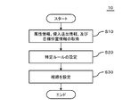
- FIG. 4 is a flowchart showing an example of the route setting process performed by the route setting device 10.
- the acquisition unit 110 of the route setting device 10 acquires attribute information, entry / exit information, and target position information of a moving body (step S10 in FIG. 4).
- step S10 in FIG. 4 a specific example of a method of acquiring each information will be described.
- the attribute information of the mobile unit is stored in the storage unit of the route setting device 10, for example.
- the acquisition unit 110 reads the attribute information of the moving body from this storage unit.
- the attribute information of the mobile unit may be stored in an external storage device.
- the acquisition unit 110 acquires the attribute information of the moving body from this storage device.
- the external storage device may store the attribute information of the moving body in association with the moving body identification information for identifying the moving body (for example, the number written on the license plate, the chassis number, etc.). ..
- the acquisition unit 110 acquires the mobile body identification information and transmits the mobile body identification information to an external storage device.
- the storage device transmits the attribute information corresponding to the received mobile body identification information to the acquisition unit 110.
- the mobile body identification information may be stored in advance in the route setting device 10 or may be acquired from the mobile body control device 20.
- the acquisition unit 110 acquires the entry / exit information using, for example, the moving route of the mobile body and the map data.
- a travel route connecting the starting point (or the current position) and the target point is set by using, for example, a car navigation program.
- the route information indicating the moving route includes the intersection where the route setting device 10 should set the route.
- the route setting device 10 can identify the target intersection by using the route information, and the road (hereinafter, referred to as an entrance route) that is passed when entering the intersection, and the intersection. It is possible to specify a road (hereinafter, referred to as an exit route) to pass when exiting.
- the route setting device 10 can use the map data stored in the map data storage unit 30.
- This map data includes, as information indicating a road (hereinafter, referred to as road information), information indicating a lane of the road (for example, presence or absence of a right turn lane, presence or absence of a left turn lane). Therefore, the moving body control device 20 can specify the lane that the moving body should pass through on each of the approach road and the exit road by using the route information and the map data.
- the road information includes information indicating the end of the road at the intersection (hereinafter referred to as end information).
- the acquisition unit 110 acquires the end information on the approach road as at least a part of the information indicating the approach position, and acquires the end information on the exit road as at least a part of the information indicating the exit position.
- the edge information is the edge of the link.
- the acquisition unit 110 identifies the lane in which the moving body should pass on the approach road, and then recognizes the position corresponding to the end of the link in the lane as the approach position to the intersection. Further, the acquisition unit 110 identifies the lane in which the moving body should pass on the exit road, and then recognizes the position corresponding to the end of the link in the lane as the exit position from the intersection.
- the entry / exit information may be input by the passenger of the moving body or its agent.
- the passenger or his / her agent inputs the entry / exit information by selecting each of the entry position and the exit position from the intersection displayed on the display, for example.
- the device for input may be a terminal operated by the person who inputs, or may be a part of the route setting device 10.
- the target position information is stored in, for example, the map data storage unit 30.
- the target position information indicates the position where the route of the moving body should pass at least near it.
- the map data storage unit 30 preferably stores the target position information in association with each intersection. In this case, the acquisition unit 110 acquires the target position information associated with the target intersection.
- the destination position information may be changed according to a combination of information identifying an intersection (or information identifying the type of intersection) and attribute information of the moving body.
- the target position information is stored for each intersection (or type of intersection) and for each attribute information of the moving body.
- the type of intersection is defined using the number of roads intersecting at the intersection, the number of lanes on each road, the angle at which the road intersects at the intersection, and the like.
- the map data storage unit 30 stores, for example, for each intersection, target position information for small vehicles, target position information for large vehicles, and target position information for trailers.
- the acquisition unit 110 selects and acquires the target position information corresponding to the attribute information of the moving body from the target position information associated with the target intersection.
- the destination position information may be changed according to the information that identifies the type of intersection.
- the destination information may be stored for each type of intersection.
- the acquisition unit 110 specifies the type of the target intersection using the road information stored in the map data storage unit 30 and acquires the target position information corresponding to the specified type.
- the target position information may be further stored in association with the combination of the entry lane and the exit lane of the moving body.
- the acquisition unit 110 uses the road information and the movement data stored in the map data storage unit 30 to identify the approach lane and the exit lane at the target intersection, and determines the combination of the identified lanes. Obtain the corresponding destination position information.
- the target position information may be stored in association with only the attribute information of the moving body.
- the acquisition unit 110 selects and acquires the target position information corresponding to the attribute information of the moving body.
- the specific rule setting unit 120 uses the attribute information of the moving body to set a specific rule used when setting a route (step S20).
- This specific rule is, for example, a program that describes an arithmetic expression, and is stored in advance in, for example, the storage unit of the route setting device 10 or the map data storage unit 30. Inputs to the program include entry and exit information and target position information.
- the storage unit or the map data storage unit 30 described above may store a plurality of specific rules in association with the attribute information of the mobile body in which the specific rules are to be used.
- the storage unit or the map data storage unit 30 described above stores a specific rule for a small vehicle, a specific rule for a large vehicle, and a specific rule for a trailer.
- the specific rule setting unit 120 reads the specific rule corresponding to the attribute information acquired in step S10 from the storage unit or the map data storage unit 30.
- the specific rule setting unit 120 determines the value of this parameter using the attribute information acquired in step S10, and the determined value is stored in the program described above. You may set a specific rule by inserting.
- the storage unit or the map data storage unit 30 described above may store the specific rule described above in association with each intersection.
- the specific rule differs depending on the intersection.
- the specific rule setting unit 120 reads the specific rule corresponding to the intersection to be processed from the storage unit or the map data storage unit 30 described above.
- a plurality of intersections may be a set, and one specific rule may be set for the set.
- the map data storage unit 30 may store the above-described specific rule as a part of the map data in a state corresponding to the attribute information of the moving body and not directly linked to the intersection.
- the route setting unit 130 sets the route along which the moving body should move by setting and processing the entry / exit information and the target position information in the specific rule set in step S20 (step S30).
- FIG. 5 is a diagram showing a first example of the route R set for the intersection 800.
- the intersection 800 shown in this figure is a crossroad, and each road has two lanes.
- the route setting device 10 sets a route R for the mobile unit 900 to turn right at an intersection.
- the map data stored in the map data storage unit 30 includes a target 830a indicating an approach path 840a of the moving body 900, an exit path link 840b of the moving body 900, and a target position 830 indicating the intersection 800.
- the acquisition unit 110 reads the links 840a and 840b and the target position information from the map data storage unit 30.
- the acquisition unit 110 recognizes the portion corresponding to the end 842a of the link 840a on the intersection 800 side of the traveling lane of the moving body 900 on the approach road as the approach position 810.
- the acquisition unit 110 recognizes the portion corresponding to the end 842b of the link 840b on the intersection 800 side of the traveling lane of the moving body 900 on the exit route as the exit position 820.
- the route setting unit 130 sets the route R of the moving body 900 so as to connect the ends 842a and 842b. At that time, the route overlaps the target position 830 or passes near the target position 830.
- the route R of the moving body 900 differs depending on the position of the target position 830. For example, as shown in FIG. 6, as the target position 830 moves to the outer peripheral side of the intersection 800, the route R also moves to the outside of the intersection 800. Therefore, the route setting device 10 can set the route R suitable for the moving body 900 by changing the target position 830 according to the attribute of the moving body 900.
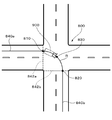
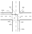
- FIG. 7 and 8 are diagrams showing a second example of the route set for the intersection 800.
- at least one of the approach road and the exit road (both in the example shown in the figure) to the intersection 800 has a plurality of lanes.
- the map data stored in the map data storage unit 30 includes these pieces of information.
- the acquisition unit 110 of the route setting device 10 uses the route information indicating the movement route of the moving body 900, so that the lane through which the moving body 900 enters the intersection 800 and the moving body 900 from the intersection 800.
- Each of the lanes to pass through when exiting is specified and these are used as part of the entry / exit information. That is, in the example shown in this figure, the entry / exit information includes information that identifies one of the plurality of lanes.
- the acquisition unit 110 sets the position of the specified lane overlapping the end of the link 840 as the entry position or the exit position of the 8900. Then, as shown in FIGS. 7 and 8, if the lane in which the moving body 900 enters the intersection 800 (or the lane in which the moving body 900 exits from the intersection 800) is different, the route R that the moving body 900 should take is also different.
- the route setting device 10 can set a route for the moving body 900 to pass through a predetermined portion of the road while bending according to the attribute of the moving body 900. Therefore, the moving body 900 can bend the above-mentioned predetermined portion of the road in a stable state.
- FIG. 9 is a diagram for explaining the usage environment of the route setting device 10 according to the second embodiment.
- the moving body 900 has a sensor 40 and an analyzing device 50.
- the sensor 40 is, for example, a LiDAR (Light Detection and Ranging) or an imaging device.
- the analysis device 50 analyzes the data generated by the sensor 40 to generate information indicating the state around the moving body 900 (hereinafter, referred to as ambient information).
- the surrounding information includes the position of the stop line of the road and the position of the line or mark indicating the running route drawn in the intersection in a state of being linked to the information that identifies the type of the line or mark. There is. Then, the acquisition unit 110 of the route setting device 10 generates at least one of the target position information and the entry / exit information using the surrounding information described above.
- the route setting device 10 sets a predetermined line or mark that should be drawn in the intersection at the target position. Then, the acquisition unit 110 of the route setting device 10 recognizes the position of the above-described predetermined line or mark from the surrounding information, and sets the recognized position as the target position.
- the acquisition unit 110 recognizes the position of the stop line of the approach road from the surrounding information and sets this position as the approach position.
- the acquisition unit 110 also sets the start position of the lane defining the exit route as the exit position.
- the moving body 900 can turn the above-mentioned predetermined portion of the road in a stable state. Even if the map data storage unit 30 does not store the target position information, the target position information can be generated using the data generated by the sensor 40.
- route setting device 20 moving body control device 30 map data storage unit 40 sensor 50 analysis device 110 acquisition unit 120 specific rule setting unit 130 route setting unit 800 intersection 810 entry position 820 exit position 830 target position 840, 840a, 840b link 842a, 842b Edge 900 Mobile R route
Landscapes
- Engineering & Computer Science (AREA)
- Radar, Positioning & Navigation (AREA)
- Remote Sensing (AREA)
- Automation & Control Theory (AREA)
- Transportation (AREA)
- Mechanical Engineering (AREA)
- Physics & Mathematics (AREA)
- General Physics & Mathematics (AREA)
- Human Computer Interaction (AREA)
- Navigation (AREA)
- Traffic Control Systems (AREA)
- Control Of Driving Devices And Active Controlling Of Vehicle (AREA)
Abstract
Description
前記移動体の属性情報、前記所定部分への進入位置及び前記所定部分からの退出位置を特定する進入退出情報、並びに前記所定部分内に位置している目標位置を示す目標位置情報を取得する取得部と、
前記進入退出情報及び前記目標位置情報を用いて前記経路を特定する際に用いられる特定ルールを、前記属性情報を用いて設定する特定ルール設定部と、
前記特定ルール、前記進入退出情報、及び前記目標位置情報を用いて前記経路を設定する経路設定部と、
を備える経路設定装置である。
コンピュータが、
前記移動体の属性情報、前記所定部分への進入位置及び前記所定部分からの退出位置を特定する進入退出情報、並びに前記所定部分内に位置している目標位置を示す目標位置情報を取得し、
前記進入退出情報及び前記目標位置情報を用いて前記経路を特定する際に用いられる特定ルールを、前記属性情報を用いて設定し、
前記特定ルール、前記進入退出情報、及び前記目標位置情報を用いて前記経路を設定する、経路設定方法である。
前記道路情報が示す道路の所定部分を移動体が曲がりながら通過するための経路を設定する際に用いられる特定ルールを、前記移動体の属性情報に紐付いた状態で含んでいる地図データである。
前記道路情報が示す道路の所定部分を移動体が曲がりながら通過するための経路を設定する際に用いられる特定ルールを、前記所定部分に紐付いた状態で含んでいる地図データである。
図1は、第1の実施形態に係る経路設定装置10の使用環境を示す図である。経路設定装置10は、移動体が曲がりながら道路の所定部分を通過するための経路を設定する装置であり、地図データ記憶部30とともに使用される。経路設定装置10は、上記した経路を設定する際に、地図データ記憶部30が記憶している地図データを用いる。地図データ記憶部30が記憶している地図データには、経路設定装置10が上記した経路を設定する際に用いる様々な情報が含まれている。
図9は、第2の実施形態に係る経路設定装置10の使用環境を説明するための図である。本図に示す例において、移動体900はセンサ40及び解析装置50を有している。センサ40は例えばLiDAR(Light Detection and Ranging)又は撮像装置である。解析装置50は、センサ40が生成したデータを解析することにより、移動体900の周囲の状態を示す情報(以下、周囲情報と記載)を生成する。周囲情報は、道路の停止線の位置、及び、交差点の中に描かれている走行路を示す線やマークの位置を、その線やマークの種類を特定する情報に紐づけた状態で含んでいる。そして経路設定装置10の取得部110は、上記した周囲情報を用いて目標位置情報及び進入退出情報の少なくとも一方を生成する。
20 移動体制御装置
30 地図データ記憶部
40 センサ
50 解析装置
110 取得部
120 特定ルール設定部
130 経路設定部
800 交差点
810 進入位置
820 退出位置
830 目標位置
840,840a,840b リンク
842a,842b 端
900 移動体
R 経路
Claims (13)
- 移動体が曲がりながら道路の所定部分を通過するための経路を設定する経路設定装置であって、
前記移動体の属性情報、前記所定部分への進入位置及び前記所定部分からの退出位置を特定する進入退出情報、並びに前記所定部分内に位置している目標位置を示す目標位置情報を取得する取得部と、
前記進入退出情報及び前記目標位置情報を用いて前記経路を特定する際に用いられる特定ルールを、前記属性情報を用いて設定する特定ルール設定部と、
前記特定ルール、前記進入退出情報、及び前記目標位置情報を用いて前記経路を設定する経路設定部と、
を備える経路設定装置。 - 請求項1に記載の経路設定装置において、
前記所定部分は交差点である経路設定装置。 - 請求項2に記載の経路設定装置において、
前記交差点への進入側の道路、及び退出側の道路の少なくとも一方は複数の車線を有しており、
前記進入退出情報は、前記複数の車線の一つを特定する情報を、前記進入位置又は前記退出位置を示す情報として含む経路設定装置。 - 請求項2又は3に記載の経路設定装置において、
前記経路設定装置は地図情報を利用可能であり、
前記地図情報は、前記交差点につながる車線の前記交差点側の端の位置を示す端情報を有しており、
前記交差点への進入位置及び前記交差点からの退出位置は、前記交差点の端の位置であり、
前記取得部は、前記端情報を前記進入退出情報の少なくとも一部として取得し、
前記特定ルールは前記経路を算出するための演算式を含む経路設定装置。 - 請求項1~4のいずれか一項に記載の経路設定装置において、
前記移動体は車両であり、
前記属性情報は、前記車両の全長、車幅、最小回転半径、ホイールベース、フロントオーバーハング、リアオーバーハング、及び車種区分の少なくとも一つを含んでいる経路設定装置。 - 請求項1~5のいずれか一項に記載の経路設定装置において、
前記目標位置情報は前記属性情報に紐付いており、
前記取得部は、当該取得部が取得した前記属性情報に対応する前記目標位置情報を取得する経路設定装置。 - 請求項1~6のいずれか一項に記載の経路設定装置において、
前記特定ルールは前記所定部分の属性に紐付いており、
前記取得部は、前記所定部分の属性をさらに取得し、当該属性に対応する前記特定ルールを取得する経路設定装置。 - 請求項1~7のいずれか一項に記載の経路設定装置において、
前記取得部は、地図情報を記憶している地図情報記憶部から前記目標位置情報を取得する経路設定装置。 - 請求項1~7のいずれか一項に記載の経路設定装置において、
前記目標位置情報は、前記移動体に取り付けられたセンサが生成したデータを用いて生成されている経路設定装置。 - 移動体が曲がりながら道路の所定部分を通過する際の経路を設定する経路設定方法であって、
コンピュータが、
前記移動体の属性情報、前記所定部分への進入位置及び前記所定部分からの退出位置を特定する進入退出情報、並びに前記所定部分内に位置している目標位置を示す目標位置情報を取得し、
前記進入退出情報及び前記目標位置情報を用いて前記経路を特定する際に用いられる特定ルールを、前記属性情報を用いて設定し、
前記特定ルール、前記進入退出情報、及び前記目標位置情報を用いて前記経路を設定する、経路設定方法。 - コンピュータを、請求項1~9のいずれか一項に記載の経路設定装置として機能させるためのプログラム。
- 道路情報と、
前記道路情報が示す道路の所定部分を移動体が曲がりながら通過するための経路を設定する際に用いられる特定ルールを、前記移動体の属性情報に紐付いた状態で含んでいる地図データ。 - 道路情報と、
前記道路情報が示す道路の所定部分を移動体が曲がりながら通過するための経路を設定する際に用いられる特定ルールを、前記所定部分に紐付いた状態で含んでいる地図データ。
Priority Applications (3)
| Application Number | Priority Date | Filing Date | Title |
|---|---|---|---|
| EP19885389.7A EP3882575B1 (en) | 2018-11-14 | 2019-11-12 | Route setting device, route setting method and program |
| US17/294,229 US20220018680A1 (en) | 2018-11-14 | 2019-11-12 | Route setting apparatus, route setting method, program, and map data |
| JP2020555705A JP7252253B2 (ja) | 2018-11-14 | 2019-11-12 | 経路設定装置、経路設定方法、及びプログラム |
Applications Claiming Priority (2)
| Application Number | Priority Date | Filing Date | Title |
|---|---|---|---|
| JP2018213529 | 2018-11-14 | ||
| JP2018-213529 | 2018-11-14 |
Publications (1)
| Publication Number | Publication Date |
|---|---|
| WO2020100868A1 true WO2020100868A1 (ja) | 2020-05-22 |
Family
ID=70730265
Family Applications (1)
| Application Number | Title | Priority Date | Filing Date |
|---|---|---|---|
| PCT/JP2019/044274 Ceased WO2020100868A1 (ja) | 2018-11-14 | 2019-11-12 | 経路設定装置、経路設定方法、プログラム、及び地図データ |
Country Status (4)
| Country | Link |
|---|---|
| US (1) | US20220018680A1 (ja) |
| EP (1) | EP3882575B1 (ja) |
| JP (1) | JP7252253B2 (ja) |
| WO (1) | WO2020100868A1 (ja) |
Families Citing this family (2)
| Publication number | Priority date | Publication date | Assignee | Title |
|---|---|---|---|---|
| JP7200820B2 (ja) * | 2019-05-13 | 2023-01-10 | 株式会社デンソー | 物標識別装置および運転支援装置 |
| CN115375241A (zh) * | 2022-08-30 | 2022-11-22 | 中国银行股份有限公司 | 路线规划方法、装置、存储介质和设备 |
Citations (4)
| Publication number | Priority date | Publication date | Assignee | Title |
|---|---|---|---|---|
| JP2004294142A (ja) * | 2003-03-26 | 2004-10-21 | Nissan Diesel Motor Co Ltd | 走行経路情報記憶装置 |
| JP2006273230A (ja) | 2005-03-30 | 2006-10-12 | Aisin Aw Co Ltd | 車両制御装置及び車両制御方法 |
| CN105575151A (zh) * | 2016-01-19 | 2016-05-11 | 长安大学 | 考虑车辆类型及平面交叉口延误的gps导航路径优化方法 |
| JP2018087763A (ja) * | 2016-11-29 | 2018-06-07 | アルパイン株式会社 | 走行可能領域設定装置および走行可能領域設定方法 |
Family Cites Families (5)
| Publication number | Priority date | Publication date | Assignee | Title |
|---|---|---|---|---|
| JP5353097B2 (ja) * | 2008-07-22 | 2013-11-27 | 朝日航洋株式会社 | 道路網データ生成装置及び交差点内車線生成装置、並びにこれらの方法及びプログラム |
| US10013508B2 (en) * | 2014-10-07 | 2018-07-03 | Toyota Motor Engineering & Manufacturing North America, Inc. | Joint probabilistic modeling and inference of intersection structure |
| CN108885108B (zh) * | 2016-01-14 | 2022-05-10 | 福特全球技术公司 | 基于操纵难度的u形转弯辅助 |
| JP6544348B2 (ja) * | 2016-12-22 | 2019-07-17 | トヨタ自動車株式会社 | 車両運転支援装置 |
| WO2019180963A1 (ja) * | 2018-03-23 | 2019-09-26 | 三菱電機株式会社 | 走行支援システム、走行支援方法、および走行支援プログラム |
-
2019
- 2019-11-12 EP EP19885389.7A patent/EP3882575B1/en active Active
- 2019-11-12 WO PCT/JP2019/044274 patent/WO2020100868A1/ja not_active Ceased
- 2019-11-12 JP JP2020555705A patent/JP7252253B2/ja active Active
- 2019-11-12 US US17/294,229 patent/US20220018680A1/en not_active Abandoned
Patent Citations (4)
| Publication number | Priority date | Publication date | Assignee | Title |
|---|---|---|---|---|
| JP2004294142A (ja) * | 2003-03-26 | 2004-10-21 | Nissan Diesel Motor Co Ltd | 走行経路情報記憶装置 |
| JP2006273230A (ja) | 2005-03-30 | 2006-10-12 | Aisin Aw Co Ltd | 車両制御装置及び車両制御方法 |
| CN105575151A (zh) * | 2016-01-19 | 2016-05-11 | 长安大学 | 考虑车辆类型及平面交叉口延误的gps导航路径优化方法 |
| JP2018087763A (ja) * | 2016-11-29 | 2018-06-07 | アルパイン株式会社 | 走行可能領域設定装置および走行可能領域設定方法 |
Non-Patent Citations (1)
| Title |
|---|
| See also references of EP3882575A4 |
Also Published As
| Publication number | Publication date |
|---|---|
| EP3882575B1 (en) | 2025-04-16 |
| EP3882575A1 (en) | 2021-09-22 |
| JP7252253B2 (ja) | 2023-04-04 |
| US20220018680A1 (en) | 2022-01-20 |
| JPWO2020100868A1 (ja) | 2020-05-22 |
| EP3882575A4 (en) | 2022-08-24 |
Similar Documents
| Publication | Publication Date | Title |
|---|---|---|
| CN111880533B (zh) | 驾驶场景重构方法、装置、系统、车辆、设备及存储介质 | |
| JP6832421B2 (ja) | シミュレーションに基づく自動運転車の感知要求の評価方法 | |
| CN112001986B (zh) | 虚拟车道的生成方法、装置以及电子设备和存储介质 | |
| JP6757442B2 (ja) | 自動運転車における車線後処理 | |
| JP2020015493A (ja) | 自動運転車両のためのオブジェクト移動を予測するための方法およびシステム | |
| JP2022041923A (ja) | 接続されたデータ分析プラットフォームを用いた車両経路指定 | |
| EP3627110B1 (en) | Method for planning trajectory of vehicle | |
| US11940287B2 (en) | Device and method for route planning | |
| CN110662683A (zh) | 驾驶辅助装置以及驾驶辅助方法 | |
| KR20200037119A (ko) | 자율 주행 차량에 사용되는 터널에 기초한 계획 시스템 | |
| EP3588007A1 (en) | Information processing method and information processing device | |
| US20210295683A1 (en) | Traffic safety control method and vehicle-mounted device | |
| JP2022011837A (ja) | 車両 | |
| CN115257754A (zh) | 车辆会车控制方法、装置、设备及存储介质 | |
| JP7252253B2 (ja) | 経路設定装置、経路設定方法、及びプログラム | |
| JP2019164602A (ja) | 逆走警告システム、逆走警告方法、及び逆走警告プログラム | |
| US20220415163A1 (en) | Route control device and route control method | |
| CN115092186A (zh) | 一种车辆自动驾驶方法及装置、电子设备、存储介质 | |
| US20240240953A1 (en) | Information processing device | |
| JP7158502B2 (ja) | 情報処理装置、および情報処理システム | |
| TWI762887B (zh) | 交通安全管控方法、車載裝置及可讀儲存介質 | |
| US12606193B2 (en) | Method for determining an optimal location to wait for a left turn to minimize traffic impact | |
| US20250083701A1 (en) | Action planning apparatus and action planning method | |
| CN120351950A (zh) | 车道信息显示方法、装置、电子设备及车辆 | |
| JP6883402B2 (ja) | 情報処理システム、情報処理装置、情報処理方法および情報処理プログラム |
Legal Events
| Date | Code | Title | Description |
|---|---|---|---|
| 121 | Ep: the epo has been informed by wipo that ep was designated in this application |
Ref document number: 19885389 Country of ref document: EP Kind code of ref document: A1 |
|
| ENP | Entry into the national phase |
Ref document number: 2020555705 Country of ref document: JP Kind code of ref document: A |
|
| NENP | Non-entry into the national phase |
Ref country code: DE |
|
| ENP | Entry into the national phase |
Ref document number: 2019885389 Country of ref document: EP Effective date: 20210614 |
|
| WWG | Wipo information: grant in national office |
Ref document number: 2019885389 Country of ref document: EP |