WO2020105538A1 - 水中音響通信システム及び受信装置 - Google Patents
水中音響通信システム及び受信装置Info
- Publication number
- WO2020105538A1 WO2020105538A1 PCT/JP2019/044684 JP2019044684W WO2020105538A1 WO 2020105538 A1 WO2020105538 A1 WO 2020105538A1 JP 2019044684 W JP2019044684 W JP 2019044684W WO 2020105538 A1 WO2020105538 A1 WO 2020105538A1
- Authority
- WO
- WIPO (PCT)
- Prior art keywords
- wave
- signal sequences
- underwater acoustic
- acoustic communication
- communication system
- Prior art date
- Legal status (The legal status is an assumption and is not a legal conclusion. Google has not performed a legal analysis and makes no representation as to the accuracy of the status listed.)
- Ceased
Links
Images


Classifications
-
- H—ELECTRICITY
- H04—ELECTRIC COMMUNICATION TECHNIQUE
- H04B—TRANSMISSION
- H04B7/00—Radio transmission systems, i.e. using radiation field
- H04B7/02—Diversity systems; Multi-antenna system, i.e. transmission or reception using multiple antennas
- H04B7/04—Diversity systems; Multi-antenna system, i.e. transmission or reception using multiple antennas using two or more spaced independent antennas
- H04B7/06—Diversity systems; Multi-antenna system, i.e. transmission or reception using multiple antennas using two or more spaced independent antennas at the transmitting station
- H04B7/0613—Diversity systems; Multi-antenna system, i.e. transmission or reception using multiple antennas using two or more spaced independent antennas at the transmitting station using simultaneous transmission
- H04B7/0615—Diversity systems; Multi-antenna system, i.e. transmission or reception using multiple antennas using two or more spaced independent antennas at the transmitting station using simultaneous transmission of weighted versions of same signal
- H04B7/0617—Diversity systems; Multi-antenna system, i.e. transmission or reception using multiple antennas using two or more spaced independent antennas at the transmitting station using simultaneous transmission of weighted versions of same signal for beam forming
-
- H—ELECTRICITY
- H04—ELECTRIC COMMUNICATION TECHNIQUE
- H04B—TRANSMISSION
- H04B11/00—Transmission systems employing ultrasonic, sonic or infrasonic waves
-
- H—ELECTRICITY
- H04—ELECTRIC COMMUNICATION TECHNIQUE
- H04B—TRANSMISSION
- H04B13/00—Transmission systems characterised by the medium used for transmission, not provided for in groups H04B3/00 - H04B11/00
- H04B13/02—Transmission systems in which the medium consists of the earth or a large mass of water thereon, e.g. earth telegraphy
-
- H—ELECTRICITY
- H04—ELECTRIC COMMUNICATION TECHNIQUE
- H04B—TRANSMISSION
- H04B7/00—Radio transmission systems, i.e. using radiation field
- H04B7/02—Diversity systems; Multi-antenna system, i.e. transmission or reception using multiple antennas
- H04B7/04—Diversity systems; Multi-antenna system, i.e. transmission or reception using multiple antennas using two or more spaced independent antennas
- H04B7/08—Diversity systems; Multi-antenna system, i.e. transmission or reception using multiple antennas using two or more spaced independent antennas at the receiving station
- H04B7/0837—Diversity systems; Multi-antenna system, i.e. transmission or reception using multiple antennas using two or more spaced independent antennas at the receiving station using pre-detection combining
- H04B7/0842—Weighted combining
- H04B7/0848—Joint weighting
-
- Y—GENERAL TAGGING OF NEW TECHNOLOGICAL DEVELOPMENTS; GENERAL TAGGING OF CROSS-SECTIONAL TECHNOLOGIES SPANNING OVER SEVERAL SECTIONS OF THE IPC; TECHNICAL SUBJECTS COVERED BY FORMER USPC CROSS-REFERENCE ART COLLECTIONS [XRACs] AND DIGESTS
- Y02—TECHNOLOGIES OR APPLICATIONS FOR MITIGATION OR ADAPTATION AGAINST CLIMATE CHANGE
- Y02D—CLIMATE CHANGE MITIGATION TECHNOLOGIES IN INFORMATION AND COMMUNICATION TECHNOLOGIES [ICT], I.E. INFORMATION AND COMMUNICATION TECHNOLOGIES AIMING AT THE REDUCTION OF THEIR OWN ENERGY USE
- Y02D30/00—Reducing energy consumption in communication networks
- Y02D30/70—Reducing energy consumption in communication networks in wireless communication networks
Definitions
- the present invention relates to an underwater acoustic communication system and a receiving device.
- an underwater acoustic communication system may utilize a plurality of wave transmitters that transmit sound waves to spatially multiplex a plurality of signal sequences.
- An underwater acoustic communication system may utilize MIMO (Multiple Input Multiple Output) technology to efficiently spatially multiplex a plurality of signal sequences.
- MIMO Multiple Input Multiple Output
- MIMO technology is widely used in aerial wireless communication such as wireless LAN (Local Area Network).
- wireless LAN Local Area Network
- the propagation path of the wireless communication hardly changes within the time when the receiving device receives the signal sequence of one packet. Therefore, the preamble for estimating the channel response of wireless communication is placed at the beginning of the packet of the signal sequence.
- the wireless communication system can estimate the channel response of the wireless communication based on the preamble placed at the beginning of the packet of the signal sequence.
- the packet length of the signal sequence of underwater acoustic communication is longer than the packet length of the signal sequence of wireless communication in the air.
- the propagation speed of sound waves is extremely slower than the propagation speed of radio waves. Therefore, the packet length with respect to the wavelength of the sound wave of the signal sequence of the underwater acoustic communication is extremely shorter than the packet length with respect to the wavelength of the radio wave of the signal sequence of the wireless communication.
- the propagation path of the underwater acoustic communication largely changes within the time when the receiving device receives the signal sequence of one packet. Therefore, the conventional underwater acoustic communication system may not be able to estimate the channel response of the underwater acoustic communication based on the preamble arranged at the beginning of the packet of the signal sequence.
- the underwater acoustic communication system complements the signal sequence between pilot subcarriers of OFDM (Orthogonal Frequency Division Multiplexing) arranged on the frequency axis, and the underwater acoustic communication system propagates the underwater acoustic communication channel for each symbol of the signal sequence.
- OFDM Orthogonal Frequency Division Multiplexing
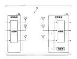
- FIG. 5 is a diagram showing a configuration example of a conventional underwater acoustic communication system 1a.
- the underwater acoustic communication system 1a includes a transmitter 2a and a receiver 3a.
- the transmitter 2a includes a modulator and N (N is an integer of 2 or more) number of wave transmitters.
- N is an integer of 2 or more
- the signal sequence to be transmitted will be referred to as "transmission signal sequence”.
- the received signal sequence will be referred to as a “received signal sequence”.
- the modulator generates N modulated signals by modulating the N transmitted signal sequences.
- the N transmitters convert the N modulated signals into sound waves.
- the N wave transmitters use sound waves as carrier waves to radiate N modulated signals into water.
- the receiving device 3a includes M (M is an integer of 2 or more) number of wave receivers, an estimation unit, and a demodulation unit.
- M wave receivers convert the received sound waves into M received signal sequences.
- the estimator estimates the channel response from the N transmitters to the M receivers based on the M received signal signals.
- the demodulation unit demodulates N transmission signal sequences from M reception signal signals based on the estimated channel response.
- an underwater acoustic communication system measures a phase amplitude response in a specific frequency region.
- the underwater acoustic communication system transforms the measurement result into a phase amplitude response in the time domain by executing an inverse fast Fourier transform on the measurement result.
- the underwater acoustic communication system estimates a channel response in the time domain based on the measurement result converted into the time domain.
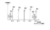
- FIG. 6 is a diagram showing an example of a direct wave signal of a pilot signal and a multipath wave of a pilot signal.
- the horizontal axis represents frequency (subcarrier number).
- the vertical axis represents the received power.
- FIG. 6 shows the direct wave signal 200 of the pilot signal, the multipath wave signals 201 to 202 of the pilot signal, and the data signals 300 to 303.
- the sound wave transmitted from the transmitter arrives at the receiver through various paths (multipath) due to reflection and diffraction. Therefore, the arrival angle of the sound wave is different for each path of the sound wave.
- the transmitter or the receiver moves, independent Doppler fluctuations are generated in the sound waves.
- multipath waves of the signal sequence are plural on the frequency axis. May cross over subcarriers.
- the conventional underwater acoustic communication system is a propagation path response of underwater acoustic communication. Cannot be estimated accurately.
- the propagation path response of underwater acoustic communication is not accurately estimated, the conventional underwater acoustic communication system has a problem that the efficiency of spatial multiplexing transmission in water cannot be improved.
- an object of the present invention is to provide an underwater acoustic communication system and a receiving device capable of improving the efficiency of spatial multiplexing transmission in water.
- One aspect of the present invention is an underwater acoustic communication system including a transmitter having N (where N is an integer of 2 or more) number of transmitters, and a receiver, wherein the receiver utilizes sound waves.
- M wave receivers for receiving M (M is an integer of 2 or more) received signal sequences in accordance with the N transmitted signal sequences transmitted from the N wave transmitters, and the received M A beamformer for suppressing multipath waves other than direct waves of the received signal sequences of L, and generating L (L is an integer of 2 or more) signal sequences from the M received signal sequences, and the generated L
- a signal estimation unit that estimates N transmission signal sequences based on the signal sequences.
- One aspect of the present invention is the above-mentioned underwater acoustic communication system, wherein a value obtained as a result of multiplying the interval of the transmitter and the interval of the receiver is the wavelength of the sound wave and the transmitter.
- the resulting value multiplied by the distance between the wave receivers is an integer multiple of the resulting value divided by the number of wave receivers.
- One aspect of the present invention is the above-described underwater acoustic communication system, wherein the N wave transmitters have directivity of sound waves toward a water surface when the transmitter is installed near a water bottom,
- the M number of receivers have directivity of sound waves coming from the bottom of the water when the receiving device is installed near the water surface.
- One aspect of the present invention is the above-mentioned underwater acoustic communication system, wherein the N wave transmitters have directivity of a sound wave toward a water bottom when the transmitter is installed near the water surface,
- the M number of receivers have directivity of sound waves coming from the water surface when the receiving device is installed near the water bottom.
- One aspect of the present invention is the above-described underwater acoustic communication system, wherein the beam former suppresses received power of the multipath wave.
- One aspect of the present invention is the above-described underwater acoustic communication system, wherein the beam former increases the signal power to interference noise power ratio of the direct wave.
- M is an integer of 2 or more
- N is an integer of 2 or more
- M receivers for receiving the received signal sequence
- L L is an integer of 2 or more
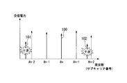
- FIG. 4 is a diagram showing an example of a direct wave signal in which received power is not suppressed in the embodiment.
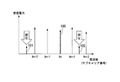
- FIG. 5 is a diagram showing an example of a direct wave signal in which received power is suppressed in the embodiment.
- FIG. 1 is a diagram showing a configuration example of an underwater acoustic communication system 1.
- the underwater acoustic communication system 1 is a system that executes underwater acoustic communication.
- the underwater acoustic communication system 1 uses a sound wave as a carrier wave.
- the underwater acoustic communication system 1 spatially multiplexes a plurality of transmission signal sequences by a multiplexing technique such as MIMO using a plurality of transmitters and receivers.
- the underwater acoustic communication system 1 includes a transmitter 2 and a receiver 3. Below, the distance (link distance) between the transmitter 2 and the receiver 3 is the distance R as an example.
- a part or all of the functional units of the transmitting device 2 and the receiving device 3 are realized by a processor such as a CPU (Central Processing Unit) executing a program stored in the storage unit.
- a processor such as a CPU (Central Processing Unit) executing a program stored in the storage unit.
- Some or all of the functional units of the transmission device 2 and the reception device 3 may be realized by using hardware such as LSI (Large Scale Integration) and ASIC (Application Specific Integrated Circuit).
- the storage unit is preferably a non-volatile recording medium (non-temporary recording medium) such as a flash memory or an HDD (Hard Disk Drive).
- the storage unit may include a volatile recording medium such as a RAM (Random Access Memory).
- the storage unit stores, for example, a signal series and a program.
- the transmission device 2 is a device that transmits a plurality of transmission signal sequences using sound waves.
- the transmitter 2 spatially multiplexes a plurality of transmission signal sequences by a multiplexing technique such as MIMO.
- the transmitter 2 is installed underwater such as under the sea (for example, near the water surface or near the water bottom).
- the transmitter 2 radiates a plurality of spatially-multiplexed transmission signal sequences into water using sound waves.
- the transmitter 2 includes a modulator 20, wave transmitters 21-1 to 21-N, and a sound collecting material 22. Below, the space
- the modulation unit 20 acquires a plurality of transmission signal sequences from an external device.
- the modulation unit 20 modulates a plurality of spatially multiplexed transmission signal sequences by a predetermined modulation method such as orthogonal frequency division multiplexing (OFDM).
- OFDM orthogonal frequency division multiplexing
- the wave transmitters 21-1 to 21-N transmit N modulated transmission signal sequences (modulation signals) using sound waves.
- the sound waves transmitted from the N wave transmitters 21 propagate in water.
- the wave transmitter 21 may have directivity of a sound wave that is difficult to radiate toward the bottom of the water.
- the wave transmitter 21 may have directivity of a sound wave that is difficult to radiate in the water surface direction.
- the wave transmitter 21 may have a sound collecting material 22 on the back surface of the wave transmitter 21.
- the N wave transmitters 21 when the wave transmitter 21 transmits N transmission signal sequences from the vicinity of the water bottom toward the water surface, the N wave transmitters 21 have the sound collecting material 22 on the water bottom side of the wave transmitter 21.
- the wave transmitter 21 transmits N transmission signal sequences toward the bottom of the water from near the water surface, the N wave transmitters 21 have the sound collecting material 22 on the water surface side of the wave transmitter 21.
- the sound collecting material 22 is a material (for example, rubber) that absorbs sound.
- the shape of the sound collecting material 22 is, for example, a flat surface.
- the sound pickup material 22 can suppress reflection of sound waves by the water surface or the water bottom.
- the receiving device 3 is a device that receives a plurality of transmission signal sequences spatially multiplexed by MIMO using sound waves.
- the receiving device 3 is installed underwater such as under the sea (for example, near the water surface or near the water bottom).
- the receiving device 3 receives a plurality of spatially multiplexed transmission signal sequences through the water.
- the receiving device 3 includes wave receivers 30-1 to 30-M, a sound collecting material 31, a beam former 32, communication lines 33-1 to 33-L (L is an integer of 2 or more), and an estimation unit. 34, a demodulation unit 35, and communication lines 36-1 to 36-N.
- the receiving apparatus 3 includes a beamformer 32 in the preceding stage of the estimation unit 34 and the demodulation unit 35 regarding the flow of signal processing on the signal sequence.
- the distance between the receivers 30 with each other as an example, the distance d r.
- the underwater acoustic communication system 1 is configured such that the distance between the wave transmitters 21 and the distance between the wave receivers 30 is Los. -It is possible to improve the efficiency of spatial multiplexing transmission in water as compared with the case where it is not defined according to the MIMO norm.
- the wave receivers 30-1 to 30-M use the sound waves to convert the N transmission signal sequences radiated from the wave transmitters 21-1 to 21-N into M reception signal sequences.
- the wave receivers 30-1 to 30-M output the received M received signal sequences to the beam former 32.
- the wave receiver 30 may have directivity of a sound wave that is difficult to radiate toward the bottom of the water when the receiving device 3 is installed near the bottom of the water.
- the wave receiver 30 may have directivity of a sound wave that is difficult to radiate in the water surface direction.
- the wave receiver 30 may have the sound collecting material 22 on the back surface of the wave receiver 30.
- the M wave receivers 30 have the sound collecting material 31 on the water bottom side of the wave receiver 30.
- the M wave receivers 30 have the sound collecting material 31 on the water surface side of the wave receiver 30.
- the sound pickup material 31 is a material (for example, rubber) that absorbs sound.
- the shape of the sound collecting material 31 is, for example, a flat surface. The sound collecting material 31 can suppress water surface reflection or bottom reflection of sound waves.
- the beam former 32 outputs L (L is an integer of 2 or more) signal sequences (internal signal sequences) from the direct waves (desired waves) of the M received signal sequences received by the M receivers 30. To generate.
- the beamformer 32 generates L signal sequences y l (t) by an arrival direction estimation process (blind process) such as MUSIC (MUltiple SIgnal Classification) method and ESPRIT (Estimation of Signal Parameters via Rotational Invariance Techniques). To do.
- the beam former 32 outputs the L signal sequences y 1 (t) to the estimation unit 34 and the demodulation unit 35 via the communication lines 33-1 to 33-L.
- the beam former 32 can estimate the arrival direction of the multipath wave by the arrival direction estimation processing such as the MUSIC method and ESPRIT.
- the beam former 32 spatially suppresses multipath waves (multiple incoming waves) other than the direct waves of the M received signal sequences received by the M wave receivers 30.
- the beam former 32 estimates the arrival directions ⁇ 1 to ⁇ ML of the multipath waves other than the direct waves of the M received signal sequences by the arrival direction estimation processing.
- the beam former 32 derives the weight matrix W for suppressing the multipath wave based on the equations (1) and (2).
- null (A) represents the orthogonal basis of the subspace orthogonal to this “A”.
- the beam former 32 derives the L signal sequences y 1 (t) from the M received signal sequences x m (t) based on the weight matrix W as in Expression (3).
- FIG. 2 is a diagram showing an example of the direct wave signal 100 in which the received power is not suppressed.
- the horizontal axis of the graph represents the frequency of the sound wave that is the carrier wave.
- the vertical axis of the graph shows the received power.
- the beam former 32 does not suppress the reception power of the multipath waves other than the direct waves of the M reception signal sequences. Therefore, the multipath wave signal 101 and the multipath wave signal 102 leak into adjacent subcarriers on the frequency axis used for transmission of the data signal.
- FIG. 3 is a diagram showing an example of the received power of the direct wave signal 100 in which the received power is suppressed.
- the horizontal axis of the graph represents the frequency of the sound wave that is the carrier wave.
- the vertical axis of the graph shows the received power.
- the beam former 32 forms a beam of a sound wave in a complementary space (a subspace where the direct waves of the M received signal sequences extend) of a subspace where the multipath waves of the M received signal sequences extend in the space of the underwater propagation path. To project. That is, the beam former 32 suppresses the reception power of the multipath waves other than the direct waves of the M reception signal sequences.
- FIG. 3 the horizontal axis of the graph represents the frequency of the sound wave that is the carrier wave.
- the vertical axis of the graph shows the received power.
- the beam former 32 forms a beam of a sound wave in a complementary space (a subspace where the direct waves of the M received signal sequences extend) of a subspace where the multipath
- the beam former 32 suppresses the reception power of the multipath wave signal 101 and the multipath wave signal 102. Thereby, the beam former 32 can prevent the multipath wave signal 101 and the multipath wave signal 102 from leaking into subcarriers adjacent to each other on the frequency axis used for transmitting the data signal.
- the beamformer 32 maximizes the signal-to-interference plus noise power ratio (SINR) of the direct wave (main wave) of the M received signal sequences in the space of the underwater propagation path.
- a beam of sound waves may be projected on a subspace (a subspace where a direct wave extends). That is, the beam former 32 may increase the signal power to interference noise power ratio of the direct waves of the M received signal sequences.
- the beamformer 32 may increase the signal power to interference noise power ratio of the direct wave signal 100.
- the beam former 32 may execute, for example, a minimum mean square error method (Minimum Mean Square Error: MMSE).
- the communication lines 33-1 to 33-L transmit the L signal sequences to the estimation unit 34 and the demodulation unit 35.
- the estimation unit 34 (signal estimation unit) estimates the underwater propagation path response based on the L signal sequences generated from the direct waves of the M received signal sequences.
- the estimation unit 34 outputs the estimation result of the underwater propagation path response to the demodulation unit 35.
- the beam former 122 suppresses the multipath wave 101 and the multipath wave 102, which are interference waves, so that the multipath wave does not leak into adjacent subcarriers. Therefore, the estimation unit 34 can improve the accuracy of estimating the channel response.
- the demodulation unit 35 demodulates (signal separation) N transmission signal sequences from L signal sequences based on the estimation result of the channel response.
- the demodulation process executed by the demodulation unit 35 is not limited to a specific demodulation process as long as it is a demodulation process corresponding to the modulation process for the transmission signal sequence.
- the beamformer 122 suppresses the multipath wave, which is an interference wave, so that the multipath wave does not leak into adjacent subcarriers. Therefore, the demodulation unit 35 can demodulate the spatially multiplexed transmission signal sequence by an arbitrary demodulation process according to the modulation process on the transmission signal sequence.
- the demodulation unit 35 outputs the N transmission signal sequences that are the demodulation results to a predetermined external device via the communication lines 36-1 to 36-N.
- the communication lines 36-1 to 36-N transmit N transmission signal sequences, which are the demodulation results of the demodulation unit 35, to a predetermined external device.
- the capacity C of the propagation path in the spatial multiplex transmission is expressed by Expression (4).
- P t represents the transmission power of the transmission signal sequence.
- H represents a channel response matrix (propagation channel response matrix).
- ⁇ n 2 represents noise power.
- I represents an identity matrix.
- ⁇ q represents the q-th eigenvalue of the channel response matrix H.
- the underwater acoustic communication system 1 can increase the capacity of the propagation path by performing the spatial multiplexing transmission.
- all eigenvalues in the propagation path response matrix have the same value.
- the underwater acoustic communication system 1 cannot increase the capacity of the propagation path even if the spatial multiplexing transmission is executed. Therefore, when the beam former 32 suppresses multipath waves, it is difficult for the underwater acoustic communication system 1 to perform spatial multiplexing transmission.
- the intervals between the transmitters 22 and the receivers 30 are geometrically determined to be appropriate intervals.
- the underwater acoustic communication system 1 forms independent propagation paths even when the beam former 32 suppresses multipath waves. Therefore, the capacity of the propagation path can be increased by the spatial multiplexing transmission.
- ⁇ represents an arbitrary natural number.
- the propagation path response vector (propagation channel response vector) h l from the l-th transmitter 22 to the M number of receivers 30 is expressed by Expression (6).
- ⁇ l represents the arrival direction of the sound wave from the l-th wave transmitter 22 in the wave receiver 30.
- the expression (5) can be approximated as the expression (8) by using the arrival direction ⁇ 1 .
- Expression (7) is expressed as Expression (9) based on Expression (8).
- d r represents the distance between the wave receivers 22.
- d t represents the distance between the wave transmitters 30.
- FIG. 4 is a flowchart showing an operation example of the underwater acoustic communication system 1.
- the M number of wave receivers 30 acquire M number of reception signal sequences according to the N number of transmission signal sequences transmitted (step S100).
- the beam former 32 suppresses multipath waves other than direct waves of M received signal sequences (step S101).
- the beam former 32 generates L signal sequences from M received signal sequences (step S102).
- the estimation unit 34 and the demodulation unit 35 estimate N transmission signal sequences based on the L signal sequences (step S103).
- the underwater acoustic communication system 1 of the embodiment includes the transmitting device 2 and the receiving device 3.
- the transmitter 2 has N wave transmitters 22.
- the reception device 3 includes M wave receivers 30, a beam former 32, an estimation unit 34, and a demodulation unit 35 (signal estimation unit).
- the M number of wave receivers 30 receive the M number of reception signal sequences in accordance with the N number of transmission signal sequences transmitted from the N number of wave transmitters 22 using the sound waves.
- the beam former 32 suppresses multipath waves other than direct waves of the received M received signal sequences.
- the beam former 32 generates L signal sequences from M received signal sequences.
- the estimation unit 34 and the demodulation unit 35 estimate N transmission signal sequences based on the generated L signal sequences.
- the beam former 32 suppresses multipath waves other than the direct waves of the M received signal sequences, the sub-forms adjacent to each other on the frequency axis used for data signal transmission are suppressed. It is possible to prevent the multipath waves of the received signal sequence from leaking into the carrier.
- the underwater acoustic communication system 1 can improve the efficiency of spatial multiplex transmission in water.
- the underwater acoustic communication system 1 can spatially multiplex a plurality of transmission signal sequences by line-of-sight MIMO even in the sea where it is difficult to estimate the propagation path response of multipath waves.
- the value obtained by multiplying the distance d t between the wave transmitter 22 and the distance d r between the wave receivers 30 is multiplied by the wavelength ⁇ of the sound wave and the distance R between the wave transmitter 22 and the wave receiver 30.
- the underwater acoustic communication system, the transmitter and the receiver in the above-described embodiments may be realized by a computer.
- the program for realizing this function may be recorded in a computer-readable recording medium, and the program recorded in this recording medium may be read by a computer system and executed.
- the “computer system” mentioned here includes an OS and hardware such as peripheral devices.
- the “computer-readable recording medium” refers to a portable medium such as a flexible disk, a magneto-optical disk, a ROM, a CD-ROM, or a storage device such as a hard disk built in a computer system.
- the "computer-readable recording medium” means to hold a program dynamically for a short time like a communication line when transmitting the program through a network such as the Internet or a communication line such as a telephone line.
- a volatile memory inside a computer system that serves as a server or a client in that case may hold a program for a certain period of time.
- the program may be for realizing some of the functions described above, or may be one that can realize the functions described above in combination with a program already recorded in the computer system, It may be realized using a programmable logic device such as FPGA (Field Programmable Gate Array).
- the present invention can be applied to a system that executes acoustic communication underwater such as undersea.
Landscapes
- Engineering & Computer Science (AREA)
- Computer Networks & Wireless Communication (AREA)
- Signal Processing (AREA)
- Mobile Radio Communication Systems (AREA)
- Measurement Of Velocity Or Position Using Acoustic Or Ultrasonic Waves (AREA)
Abstract
水中音響通信システムは、N個の送波器を有する送信装置と、受信装置とを備える水中音響通信システムであって、受信装置は、音波を利用してN個の送波器から送信されたN個の送信信号系列に応じて、M(Mは2以上の整数)個の受信信号系列を受信するM個の受波器と、受信されたM個の受信信号系列の直接波以外のマルチパス波を抑圧し、L(Lは2以上の整数)個の信号系列をM個の受信信号系列から生成するビームフォーマと、生成されたL個の信号系列に基づいてN個の送信信号系列を推定する信号推定部とを備える。
Description
本発明は、水中音響通信システム及び受信装置に関する。
水中音響通信では、搬送波となる音波に利用可能である周波数帯域が限られている。通信を高速化するため、水中音響通信システムは、音波を送信する複数の送波器を利用して、複数の信号系列を空間多重する場合がある。水中音響通信システムは、MIMO(Multiple Input Multiple Output)技術を利用して、複数の信号系列を効率的に空間多重する場合がある。
無線LAN(Local Area Network)等の空中の無線通信では、MIMO技術は広く利用されている。無線通信における、1パケットの信号系列を受信装置が受信する時間内では、無線通信の伝搬路はほぼ変動しない。このため、無線通信の伝搬路応答を推定するためのプリアンブルは、信号系列のパケットの先頭に配置されている。無線通信システムは、信号系列のパケットの先頭に配置されたプリアンブルに基づいて、無線通信の伝搬路応答を推定することが可能である。
水中音響通信では、搬送波となる音波に利用可能である周波数帯域が限られているので、水中音響通信の信号系列のパケット長は、空中の無線通信の信号系列のパケット長よりも長い。しかしながら、音波の伝搬速度は、電波の伝搬速度よりも極端に低速である。このため、水中音響通信の信号系列の音波の波長に対するパケット長は、無線通信の信号系列の電波の波長に対するパケット長よりも極端に短い。水中音響通信では、1パケットの信号系列を受信装置が受信する時間内で、水中音響通信の伝搬路は大きく変動する。このため、従来の水中音響通信システムは、信号系列のパケットの先頭に配置されたプリアンブルに基づいて、水中音響通信の伝搬路応答を推定することができない場合がある。
周波数軸上に配置されたOFDM(Orthogonal Frequency Division Multiplexing)のパイロット・サブキャリアの間の信号系列を水中音響通信システムが補完し、信号系列のシンボルごとに水中音響通信システムが水中音響通信の伝搬路応答を推定する方法が開示されている(非特許文献1参照)。
図5は、従来の水中音響通信システム1aの構成例を示す図である。水中音響通信システム1aは、送信装置2aと、受信装置3aとを備える。送信装置2aは、変調部と、N(Nは、2以上の整数)個の送波器を備える。以下、送信される信号系列を「送信信号系列」という。以下、受信された信号系列を「受信信号系列」という。変調部は、N個の送信信号系列を変調することによって、N個の変調信号を生成する。N個の送波器は、N個の変調信号を音波に変換する。N個の送波器は、音波を搬送波として利用して、N個の変調信号を水中に放射する。
受信装置3aは、M(Mは、2以上の整数)個の受波器と、推定部と、復調部とを備える。M個の受波器は、受信された音波を、M個の受信信号系列に変換する。推定部は、N個の送波器からM個の受波器までの間の伝搬路応答を、M個の受信信号信号に基づいて推定する。復調部は、推定された伝搬路応答に基づいて、N個の送信信号系列をM個の受信信号信号から復調する。
非特許文献1では、水中音響通信システムは、特定の周波数領域における位相振幅応答を計測する。水中音響通信システムは、計測結果に対して逆高速フーリエ変換を実行することによって、計測結果を時間領域における位相振幅応答に変換する。水中音響通信システムは、時間領域に変換された計測結果に基づいて、時間領域における伝搬路応答を推定する。
B. Li, J. Huang, S. Zhou, K. Ball, M. Stojanovic, L. Freitag, and P. Willett, "MIMO-OFDM for High-Rate Underwater Acoustic Communications," IEEE JOURNAL OF OCEANIC ENGINEERING, VOL. 34, NO. 4, OCTOBER 2009.
図6は、パイロット信号の直接波信号とパイロット信号のマルチパス波との例を示す図である。横軸は周波数(サブキャリア番号)を表す。縦軸は受信電力を表す。図6には、パイロット信号の直接波信号200と、パイロット信号のマルチパス波信号201~202と、データ信号300~303とが示されている。送波器から送信された音波は、反射及び回折によって、様々な経路(マルチパス)で受波器に到来する。このため、音波の到来角度は、音波の経路ごとに異なっている。送信装置又は受信装置が移動する場合、それぞれ独立のドップラー変動が音波に発生する。
水中音響通信では、音波の伝搬速度が非常に遅く、ドップラー変動は非常に大きい。このため、一定以上の周波数又は移動速度では、パイロット・サブキャリア(パイロット信号)のマルチパス波信号201~202は、データ信号300~303の伝送に利用されている隣接するサブキャリアに漏れ込む。この場合、従来の水中音響通信システムは、伝搬路応答を精度よく推定することができないという問題があった。
なお、広いサブキャリア間隔が確保された場合、隣接するサブキャリアにマルチパス波信号が漏れ込むことは回避できる。しかしながら、OFDMのシンボル長が短くなるため、従来の水中音響通信システムは、水中音響通信における長い遅延波の到来方向を推定することができないという問題があった。
このように、音波を利用して信号系列を送信する送信装置と、送信された信号系列を受信する受信装置とが水中音響通信を実行する場合、信号系列のマルチパス波が周波数軸上で複数のサブキャリアを跨ぐ場合がある。例えば、送信装置若しくは受信装置が水中を移動する場合、又は、送信装置及び受信装置が数十kbps以上の水中音響通信を実行する場合、従来の水中音響通信システムは、水中音響通信の伝搬路応答を精度よく推定することができない。水中音響通信の伝搬路応答が精度よく推定されない場合、従来の水中音響通信システムは、水中における空間多重伝送の効率を向上させることができないという問題がある。
上記事情に鑑み、本発明は、水中における空間多重伝送の効率を向上させることが可能である水中音響通信システム及び受信装置を提供することを目的としている。
本発明の一態様は、N(Nは2以上の整数)個の送波器を有する送信装置と、受信装置とを備える水中音響通信システムであって、前記受信装置は、音波を利用してN個の前記送波器から送信されたN個の送信信号系列に応じて、M(Mは2以上の整数)個の受信信号系列を受信するM個の受波器と、受信されたM個の前記受信信号系列の直接波以外のマルチパス波を抑圧し、L(Lは2以上の整数)個の信号系列をM個の前記受信信号系列から生成するビームフォーマと、生成されたL個の前記信号系列に基づいてN個の前記送信信号系列を推定する信号推定部とを備える水中音響通信システムである。
本発明の一態様は、上記の水中音響通信システムであって、前記送波器の間隔と前記受波器の間隔とが乗算された結果の値は、前記音波の波長と前記送波器及び前記受波器の間の距離とが乗算された結果の値が、前記受波器の個数で除算された結果の値の整数倍である。
本発明の一態様は、上記の水中音響通信システムであって、前記N個の送波器は、前記送信装置が水底付近に設置される場合、水面に向かう音波の指向性を有し、前記M個の受波器は、前記受信装置が水面付近に設置される場合、水底から到来する音波の指向性を有する。
本発明の一態様は、上記の水中音響通信システムであって、前記N個の送波器は、前記送信装置が水面付近に設置される場合、水底に向かう音波の指向性を有し、前記M個の受波器は、前記受信装置が水底付近に設置される場合、水面から到来する音波の指向性を有する。
本発明の一態様は、上記の水中音響通信システムであって、前記ビームフォーマは、前記マルチパス波の受信電力を抑圧する。
本発明の一態様は、上記の水中音響通信システムであって、前記ビームフォーマは、前記直接波の信号電力対干渉雑音電力比を高くする。
本発明の一態様は、音波を利用してN(Nは2以上の整数)個の送波器から送信されたN個の送信信号系列に応じて、M(Mは2以上の整数)個の受信信号系列を受信するM個の受波器と、受信されたM個の前記受信信号系列の直接波以外のマルチパス波を抑圧し、L(Lは2以上の整数)個の信号系列をM個の前記受信信号系列から生成するビームフォーマと、生成されたL個の前記信号系列に基づいてN個の前記送信信号系列を推定する信号推定部とを備える受信装置である。
本発明により、水中における空間多重伝送の効率を向上させることが可能である。
本発明の実施形態について、図面を参照して詳細に説明する。
図1は、水中音響通信システム1の構成例を示す図である。水中音響通信システム1は、水中音響通信を実行するシステムである。水中音響通信システム1は、音波を搬送波として利用する。水中音響通信システム1は、複数の送波器及び受波器を利用するMIMO等の多重化技術によって、複数の送信信号系列を空間多重する。水中音響通信システム1は、送信装置2と、受信装置3とを備える。以下では、送信装置2及び受信装置3の間の距離(リンク距離)は、一例として、距離Rである。
図1は、水中音響通信システム1の構成例を示す図である。水中音響通信システム1は、水中音響通信を実行するシステムである。水中音響通信システム1は、音波を搬送波として利用する。水中音響通信システム1は、複数の送波器及び受波器を利用するMIMO等の多重化技術によって、複数の送信信号系列を空間多重する。水中音響通信システム1は、送信装置2と、受信装置3とを備える。以下では、送信装置2及び受信装置3の間の距離(リンク距離)は、一例として、距離Rである。
送信装置2及び受信装置3の各機能部のうちの一部又は全部は、CPU(Central Processing Unit)等のプロセッサが、記憶部に記憶されたプログラムを実行することにより実現される。送信装置2及び受信装置3の各機能部のうち一部又は全部は、例えば、LSI(Large Scale Integration)やASIC(Application Specific Integrated Circuit)等のハードウェアを用いて実現されてもよい。
記憶部は、例えばフラッシュメモリ、HDD(Hard Disk Drive)などの不揮発性の記録媒体(非一時的な記録媒体)が好ましい。記憶部は、RAM(Random Access Memory)などの揮発性の記録媒体を備えてもよい。記憶部は、例えば、信号系列、プログラムを記憶する。
送信装置2は、複数の送信信号系列を、音波を利用して送信する装置である。送信装置2は、MIMO等の多重化技術によって、複数の送信信号系列を空間多重する。送信装置2は、海中等の水中(例えば、水面付近又は水底付近)に設置される。送信装置2は、空間多重された複数の送信信号系列を、音波を利用して水中に放射する。送信装置2は、変調部20と、送波器21-1~21-Nと、収音材22とを備える。以下では、送波器21同士の間隔は、一例として、距離dtである。
変調部20は、複数の送信信号系列を外部装置から取得する。変調部20は、直交周波数分割多重(Orthogonal Frequency Division Multiplexing:OFDM)等の予め定められた変調方式によって、空間多重された複数の送信信号系列を変調する。
送波器21-1~21-N(送信アンテナ)は、変調されたN個の送信信号系列(変調信号)を、音波を利用して送信する。N個の送波器21から送信された音波は、水中を伝搬する。送波器21は、水底付近に送信装置2が設置された場合、水底方向に放射しにくい音波の指向性を有してもよい。送波器21は、水面付近に送信装置2が設置された場合、水面方向に放射しにくい音波の指向性を有してもよい。送波器21は、送波器21の背面に収音材22を有してもよい。例えば、N個の送信信号系列を送波器21が水面に向けて水底付近から送信する場合、N個の送波器21は、送波器21の水底側に収音材22を有する。例えば、N個の送信信号系列を送波器21が水底に向けて水面付近から送信する場合、N個の送波器21は、送波器21の水面側に収音材22を有する。収音材22は、音を吸収する素材(例えば、ゴム)である。収音材22の形状は、例えば平面である。収音材22は、水面又は水底による音波の反射を抑制することができる。
受信装置3は、MIMOによって空間多重された複数の送信信号系列を、音波を利用して受信する装置である。受信装置3は、海中等の水中(例えば、水面付近又は水底付近)に設置される。受信装置3は、空間多重された複数の送信信号系列を、水中を介して受信する。受信装置3は、受波器30-1~30-Mと、収音材31と、ビームフォーマ32と、通信線33-1~33-L(Lは、2以上の整数)と、推定部34と、復調部35と、通信線36-1~36-Nとを備える。受信装置3は、信号系列に対する信号処理の流れに関して推定部34及び復調部35の前段に、ビームフォーマ32を備える。
以下では、受波器30同士の間隔は、一例として、距離drである。送波器21の間隔dtと、受波器30の間隔drとは、Los-MIMO(Line-of-sight MIMO)の規範に従って定められてもよい。すなわち、送波器21の間隔dtと受波器30の間隔drとが乗算された結果の値(=dt×dr)は、音波の波長λと送波器21及び受波器30の間の距離Rとが乗算された結果の値が受波器30の個数「M」で除算された結果の値(=λ×R/M)の整数倍でもよい。送波器21の間隔と受波器30の間隔とがLos-MIMOの規範に従って定められている場合、水中音響通信システム1は、送波器21の間隔と受波器30の間隔とがLos-MIMOの規範に従って定められていない場合と比較して、水中における空間多重伝送の効率を向上させることができる。
受波器30-1~30-M(受信アンテナ)は、送波器21-1~21-Nから放射されたN個の送信信号系列を、音波を利用して、M個の受信信号系列として受信する。受波器30-1~30-Mは、受信されたM個の受信信号系列を、ビームフォーマ32に出力する。
受波器30は、水底付近に受信装置3が設置された場合、水底方向に放射しにくい音波の指向性を有してもよい。受波器30は、水面付近に受信装置3が設置された場合、水面方向に放射しにくい音波の指向性を有してもよい。受波器30は、受波器30の背面に収音材22を有してもよい。例えば、M個の受信信号系列を受波器30が水底付近で受信する場合、M個の受波器30は、受波器30の水底側に収音材31を有する。例えば、M個の受信信号系列を受波器30が水面付近で受信する場合、M個の受波器30は、受波器30の水面側に収音材31を有する。収音材31は、音を吸収する素材(例えば、ゴム)である。収音材31の形状は、例えば平面である。収音材31は、音波の水面反射又は水底反射を抑制することができる。
ビームフォーマ32は、L(Lは2以上の整数)個の信号系列(内部信号系列)を、M個の受波器30によって受信されたM個の受信信号系列の直接波(希望波)から生成する。ビームフォーマ32は、例えば、MUSIC(MUltiple SIgnal Classification)法、ESPRIT(Estimation of Signal Parameters via Rotational Invariance Techniques)等の到来方向推定処理(ブラインド処理)によって、L個の信号系列yl(t)を生成する。ビームフォーマ32は、L個の信号系列yl(t)を、通信線33-1~33-Lを介して推定部34及び復調部35に出力する。
水中音響通信では、マルチパス波の到来方向の時間変動は小さい。このため、ビームフォーマ32は、MUSIC法、ESPRIT等の到来方向推定処理によって、マルチパス波の到来方向を推定可能である。
ビームフォーマ32は、M個の受波器30によって受信されたM個の受信信号系列の直接波以外のマルチパス波(多重到来波)を、空間的に抑圧する。ビームフォーマ32は、到来方向推定処理によって、M個の受信信号系列の直接波以外のマルチパス波の到来方向θ1~θM-Lを推定する。ビームフォーマ32は、マルチパス波を抑圧するためのウェイト行列Wを、式(1)及び式(2)に基づいて導出する。


ここで、null(A)は、この「A」と直交する部分空間の直交基底を表す。ビームフォーマ32は、式(3)のようにウェイト行列Wに基づいて、L個の信号系列yl(t)をM個の受信信号系列xm(t)から導出する。

図2は、受信電力が抑圧されていない直接波信号100の例を示す図である。図2において、グラフの横軸は、搬送波である音波の周波数を示す。グラフの縦軸は、受信電力を示す。図3との比較のため、図2では、ビームフォーマ32は、M個の受信信号系列の直接波以外のマルチパス波の受信電力を抑圧していない。このため、マルチパス波信号101及びマルチパス波信号102は、データ信号の伝送に利用されている周波数軸上で隣接するサブキャリアに漏れ込んでいる。
図3は、受信電力が抑圧された直接波信号100の受信電力の例を示す図である。図3において、グラフの横軸は、搬送波である音波の周波数を示す。グラフの縦軸は、受信電力を示す。ビームフォーマ32は、水中の伝搬路の空間においてM個の受信信号系列のマルチパス波が張る部分空間の補空間(M個の受信信号系列の直接波が張る部分空間)に、音波のビームを射影する。すなわち、ビームフォーマ32は、M個の受信信号系列の直接波以外のマルチパス波の受信電力を抑圧する。図3では、ビームフォーマ32は、マルチパス波信号101及びマルチパス波信号102の受信電力を抑圧する。これによって、ビームフォーマ32は、データ信号の伝送に利用されている周波数軸上で隣接するサブキャリアにマルチパス波信号101及びマルチパス波信号102が漏れ込むことを防ぐことができる。
ビームフォーマ32は、水中の伝搬路の空間においてM個の受信信号系列の直接波(主波)の信号電力対干渉雑音電力比(Signal-to-Interference plus Noise power Ratio:SINR)が最大となる部分空間(直接波が張る部分空間)に、音波のビームを射影してもよい。すなわち、ビームフォーマ32は、M個の受信信号系列の直接波の信号電力対干渉雑音電力比を高くしてもよい。図3では、ビームフォーマ32は、直接波信号100の信号電力対干渉雑音電力比を高くしてもよい。ビームフォーマ32は、例えば、最小平均二乗誤差法(Minimum Mean Square Error: MMSE)を実行してもよい。
図1に戻り、水中音響通信システム1の構成例の説明を続ける。
通信線33-1~33-Lは、L個の信号系列を推定部34及び復調部35に伝送する。推定部34(信号推定部)は、M個の受信信号系列の直接波から生成されたL個の信号系列に基づいて、水中の伝搬路応答を推定する。推定部34は、水中の伝搬路応答の推定結果を復調部35に出力する。図3に示されているように、干渉波であるマルチパス波101及びマルチパス波102をビームフォーマ122が抑圧することによって、隣接するサブキャリアにマルチパス波が漏れ込まなくなる。このため、推定部34は、伝搬路応答を推定する精度を向上させることが可能である。
通信線33-1~33-Lは、L個の信号系列を推定部34及び復調部35に伝送する。推定部34(信号推定部)は、M個の受信信号系列の直接波から生成されたL個の信号系列に基づいて、水中の伝搬路応答を推定する。推定部34は、水中の伝搬路応答の推定結果を復調部35に出力する。図3に示されているように、干渉波であるマルチパス波101及びマルチパス波102をビームフォーマ122が抑圧することによって、隣接するサブキャリアにマルチパス波が漏れ込まなくなる。このため、推定部34は、伝搬路応答を推定する精度を向上させることが可能である。
復調部35(信号推定部)は、伝搬路応答の推定結果に基づいて、N個の送信信号系列をL個の信号系列から復調(信号分離)する。復調部35が実行する復調処理は、送信信号系列に対する変調処理に応じた復調処理であれば、特定の復調処理に限定されない。図3に示されているように、干渉波であるマルチパス波をビームフォーマ122が抑圧することによって、隣接するサブキャリアにマルチパス波が漏れ込まなくなる。このため、復調部35は、送信信号系列に対する変調処理に応じた任意の復調処理によって、空間多重された送信信号系列を復調することが可能となる。
復調部35は、復調結果であるN個の送信信号系列を、通信線36-1~36-Nを介して所定の外部装置に出力する。通信線36-1~36-Nは、復調部35による復調結果であるN個の送信信号系列を、所定の外部装置に伝送する。
次に、マルチパス波が抑圧された場合について、空間多重伝送における伝搬路の容量(伝送容量)の低下について説明する。
空間多重伝送における伝搬路の容量Cは、式(4)のように表される。
空間多重伝送における伝搬路の容量Cは、式(4)のように表される。

ここで、Ptは、送信信号系列の送信電力を表す。Hは、伝搬路応答行列(伝搬チャネル応答行列)を表す。σn
2は、雑音電力を表す。Iは、単位行列を表す。λqは、伝搬路応答行列Hのq番目の固有値を表す。
多くのマルチパス波が存在する伝搬路では、2番目以降の固有値が伝搬路応答行列に存在する。この場合、水中音響通信システム1は、空間多重伝送を実行することによって、伝搬路の容量を増加させることができる。互いに完全に独立した伝搬路を形成することが可能である場合、伝搬路応答行列における全ての固有値は同じ値となる。
マルチパス波が存在しない伝搬路では、2番目以降の固有値は、非常に小さい値となる。この場合、水中音響通信システム1は、空間多重伝送を実行しても、伝搬路の容量を増加させることができない。このため、ビームフォーマ32がマルチパス波を抑圧する場合には、水中音響通信システム1は、空間多重伝送を実行することが難しい。
そこで、ビームフォーマ32がマルチパス波を抑圧する場合、送波器22の間隔と受波器30の間隔とは、幾何学的に適切な間隔にそれぞれ定められる。送波器22及び受波器30の間の経路差を適切な距離にすることによって、水中音響通信システム1は、ビームフォーマ32がマルチパス波を抑圧する場合でも、互いに独立した伝搬路を形成するので、空間多重伝送によって伝搬路の容量を増加させることができる。
波長λと、送信装置2及び受信装置3の間の距離Rと、受波器30の個数Mとの関係は、式(5)のように表される。

ここで、αは、任意の自然数を表す。式(5)に示された関係が満たされる場合、水中音響通信システム1は、互いに独立した伝搬路を形成することができる。
l番目の送波器22からM個の受波器30までの伝搬路応答ベクトル(伝搬チャネル応答ベクトル)hlは、式(6)のように表される。

ここで、θlは、受波器30における、l番目の送波器22からの音波の到来方向を表す。
互いに独立した伝搬路では、異なる送波器22からM個の受波器30までの間の伝搬路応答ベクトル同士の内積の結果は、式(7)に示されているように零となる。

到来方向θlが十分に小さい場合、式(5)は、到来方向を表すθ1を用いて、式(8)のように近似可能である。

式(7)は、式(8)に基づいて、式(9)のように表される。

ここで、drは、受波器22の間隔を表す。dtは、送波器30の間隔を表す。受波器22の間隔と送波器30の間隔とが式(9)を満たす場合、式(5)が導出される。
次に、水中音響通信システム1の動作例を説明する。
図4は、水中音響通信システム1の動作例を示すフローチャートである。M個の受波器30は、送信されたN個の送信信号系列に応じて、M個の受信信号系列を取得する(ステップS100)。ビームフォーマ32は、M個の受信信号系列の直接波以外のマルチパス波を抑圧する(ステップS101)。ビームフォーマ32は、L個の信号系列をM個の受信信号系列から生成する(ステップS102)。推定部34及び復調部35(信号推定部)は、L個の信号系列に基づいて、N個の送信信号系列を推定する(ステップS103)。
図4は、水中音響通信システム1の動作例を示すフローチャートである。M個の受波器30は、送信されたN個の送信信号系列に応じて、M個の受信信号系列を取得する(ステップS100)。ビームフォーマ32は、M個の受信信号系列の直接波以外のマルチパス波を抑圧する(ステップS101)。ビームフォーマ32は、L個の信号系列をM個の受信信号系列から生成する(ステップS102)。推定部34及び復調部35(信号推定部)は、L個の信号系列に基づいて、N個の送信信号系列を推定する(ステップS103)。
以上のように、実施形態の水中音響通信システム1は、送信装置2と、受信装置3とを備える。送信装置2は、N個の送波器22を有する。受信装置3は、M個の受波器30と、ビームフォーマ32と、推定部34及び復調部35(信号推定部)とを備える。M個の受波器30は、音波を利用してN個の送波器22から送信されたN個の送信信号系列に応じて、M個の受信信号系列を受信する。ビームフォーマ32は、受信されたM個の受信信号系列の直接波以外のマルチパス波を抑圧する。ビームフォーマ32は、L個の信号系列をM個の受信信号系列から生成する。推定部34及び復調部35は、生成されたL個の信号系列に基づいて、N個の送信信号系列を推定する。
このように、水中音響通信システム1は、M個の受信信号系列の直接波以外のマルチパス波をビームフォーマ32が抑圧するので、データ信号の伝送に利用されている周波数軸上で隣接するサブキャリアに受信信号系列のマルチパス波が漏れ込むことを防ぐことができる。
これによって、水中音響通信システム1は、水中における空間多重伝送の効率を向上させることが可能である。水中音響通信システム1は、マルチパス波の伝搬路応答の推定が難しい海中等においても、見通しMIMOによって、複数の送信信号系列を空間多重することが可能である。
送波器22の間隔dtと受波器30の間隔drとが乗算された結果の値は、音波の波長λと送波器22及び受波器30の間の距離Rとが乗算された結果の値が、受波器30の個数で除算された結果の値(=λ×R/M)の整数倍でもよい。これによって、水中音響通信システム1は、マルチパス波をビームフォーマ32が抑圧する場合でも、空間多重された音波の伝搬路応答行列の固有値を確保するので、水中における空間多重伝送の効率を向上させることが可能である。
上述した実施形態における水中音響通信システム、送信装置及び受信装置をコンピュータで実現するようにしてもよい。その場合、この機能を実現するためのプログラムをコンピュータ読み取り可能な記録媒体に記録して、この記録媒体に記録されたプログラムをコンピュータシステムに読み込ませ、実行することによって実現してもよい。なお、ここでいう「コンピュータシステム」とは、OSや周辺機器等のハードウェアを含むものとする。また、「コンピュータ読み取り可能な記録媒体」とは、フレキシブルディスク、光磁気ディスク、ROM、CD-ROM等の可搬媒体、コンピュータシステムに内蔵されるハードディスク等の記憶装置のことをいう。さらに「コンピュータ読み取り可能な記録媒体」とは、インターネット等のネットワークや電話回線等の通信回線を介してプログラムを送信する場合の通信線のように、短時間の間、動的にプログラムを保持するもの、その場合のサーバやクライアントとなるコンピュータシステム内部の揮発性メモリのように、一定時間プログラムを保持しているものも含んでもよい。また上記プログラムは、前述した機能の一部を実現するためのものであってもよく、さらに前述した機能をコンピュータシステムにすでに記録されているプログラムとの組み合わせで実現できるものであってもよく、FPGA(Field Programmable Gate Array)等のプログラマブルロジックデバイスを用いて実現されるものであってもよい。
以上、この発明の実施形態について図面を参照して詳述してきたが、具体的な構成はこの実施形態に限られるものではなく、この発明の要旨を逸脱しない範囲の設計等も含まれる。
本発明は、海中等の水中で音響通信を実行するシステムに適用可能である。
1…水中音響通信システム、1a…水中音響通信システム、2…送信装置、2a…送信
装置、3…受信装置、3a…受信装置、20…変調部20…送波器21…収音材、30…
送波器、31…収音材、32…ビームフォーマ、33…通信線、34…推定部、35…復
調部、36…通信線、100…直接波信号、101…マルチパス波信号、102…マルチ
パス波信号、200…直接波信号、201…マルチパス波信号、202…マルチパス波信
号、300~303…データ信号
装置、3…受信装置、3a…受信装置、20…変調部20…送波器21…収音材、30…
送波器、31…収音材、32…ビームフォーマ、33…通信線、34…推定部、35…復
調部、36…通信線、100…直接波信号、101…マルチパス波信号、102…マルチ
パス波信号、200…直接波信号、201…マルチパス波信号、202…マルチパス波信
号、300~303…データ信号
Claims (7)
- N(Nは2以上の整数)個の送波器を有する送信装置と、受信装置とを備える水中音響通信システムであって、
前記受信装置は、
音波を利用してN個の前記送波器から送信されたN個の送信信号系列に応じて、M(Mは2以上の整数)個の受信信号系列を受信するM個の受波器と、
受信されたM個の前記受信信号系列の直接波以外のマルチパス波を抑圧し、L(Lは2以上の整数)個の信号系列をM個の前記受信信号系列から生成するビームフォーマと、
生成されたL個の前記信号系列に基づいてN個の前記送信信号系列を推定する信号推定部と
を備える水中音響通信システム。 - 前記送波器の間隔と前記受波器の間隔とが乗算された結果の値は、前記音波の波長と前記送波器及び前記受波器の間の距離とが乗算された結果の値が、前記受波器の個数で除算された結果の値の整数倍である、
請求項1に記載の水中音響通信システム。 - 前記N個の送波器は、前記送信装置が水底付近に設置される場合、水面に向かう音波の指向性を有し、
前記M個の受波器は、前記受信装置が水面付近に設置される場合、水底から到来する音波の指向性を有する、
請求項1又は請求項2に記載の水中音響通信システム。 - 前記N個の送波器は、前記送信装置が水面付近に設置される場合、水底に向かう音波の指向性を有し、
前記M個の受波器は、前記受信装置が水底付近に設置される場合、水面から到来する音波の指向性を有する、
請求項1又は請求項2に記載の水中音響通信システム。 - 前記ビームフォーマは、前記マルチパス波の受信電力を抑圧する、
請求項1から請求項4のいずれか一項に記載の水中音響通信システム。 - 前記ビームフォーマは、前記直接波の信号電力対干渉雑音電力比を高くする、
請求項1から請求項4のいずれか一項に記載の水中音響通信システム。 - 音波を利用してN(Nは2以上の整数)個の送波器から送信されたN個の送信信号系列に応じて、M(Mは2以上の整数)個の受信信号系列を受信するM個の受波器と、
受信されたM個の前記受信信号系列の直接波以外のマルチパス波を抑圧し、L(Lは2以上の整数)個の信号系列をM個の前記受信信号系列から生成するビームフォーマと、
生成されたL個の前記信号系列に基づいてN個の前記送信信号系列を推定する信号推定部と
を備える受信装置。
Priority Applications (2)
| Application Number | Priority Date | Filing Date | Title |
|---|---|---|---|
| EP19886493.6A EP3859988B1 (en) | 2018-11-22 | 2019-11-14 | Underwater acoustic communication system and receiving device |
| US17/291,850 US11923911B2 (en) | 2018-11-22 | 2019-11-14 | Hydroacoustic communication system and receiving apparatus |
Applications Claiming Priority (2)
| Application Number | Priority Date | Filing Date | Title |
|---|---|---|---|
| JP2018-219638 | 2018-11-22 | ||
| JP2018219638A JP7168849B2 (ja) | 2018-11-22 | 2018-11-22 | 水中音響通信システム及び受信装置 |
Publications (1)
| Publication Number | Publication Date |
|---|---|
| WO2020105538A1 true WO2020105538A1 (ja) | 2020-05-28 |
Family
ID=70774032
Family Applications (1)
| Application Number | Title | Priority Date | Filing Date |
|---|---|---|---|
| PCT/JP2019/044684 Ceased WO2020105538A1 (ja) | 2018-11-22 | 2019-11-14 | 水中音響通信システム及び受信装置 |
Country Status (4)
| Country | Link |
|---|---|
| US (1) | US11923911B2 (ja) |
| EP (1) | EP3859988B1 (ja) |
| JP (1) | JP7168849B2 (ja) |
| WO (1) | WO2020105538A1 (ja) |
Cited By (3)
| Publication number | Priority date | Publication date | Assignee | Title |
|---|---|---|---|---|
| US20220271848A1 (en) * | 2019-07-01 | 2022-08-25 | Nippon Telegraph And Telephone Corporation | Communication apparatus and communication method |
| US12231180B2 (en) * | 2019-11-12 | 2025-02-18 | Nippon Telegraph And Telephone Corporation | Receiving apparatus |
| JP7843901B1 (ja) * | 2025-03-28 | 2026-04-10 | 北京世航智能科技有限公司 | 曲面に適応可能な水中ロボット及び遠隔制御介入方法 |
Families Citing this family (4)
| Publication number | Priority date | Publication date | Assignee | Title |
|---|---|---|---|---|
| CN112737702B (zh) * | 2020-12-18 | 2022-05-17 | 哈尔滨工程大学 | 一种稀疏干扰背景下的mimo水声信道估计方法 |
| JP7773770B2 (ja) * | 2021-11-24 | 2025-11-20 | 国立研究開発法人海洋研究開発機構 | 受信装置、cir計測方法及びcir計測プログラム |
| CN117544207B (zh) * | 2023-11-16 | 2025-10-21 | 哈尔滨工程大学 | 基于导频的水声mimo高速通信频差波束形成接收方法 |
| WO2025177519A1 (ja) * | 2024-02-22 | 2025-08-28 | Ntt株式会社 | 水中音響通信システム及び同期方法 |
Citations (2)
| Publication number | Priority date | Publication date | Assignee | Title |
|---|---|---|---|---|
| JPH08331065A (ja) * | 1995-05-30 | 1996-12-13 | Nec Corp | 音響通信装置 |
| WO2009017230A1 (ja) * | 2007-08-02 | 2009-02-05 | Nec Corporation | 決定論的通信路を有するmimo通信システム及びそのアンテナ配置方法 |
Family Cites Families (7)
| Publication number | Priority date | Publication date | Assignee | Title |
|---|---|---|---|---|
| US6201499B1 (en) * | 1998-02-03 | 2001-03-13 | Consair Communications | Time difference of arrival measurement system |
| DE10216037A1 (de) * | 2002-04-11 | 2003-10-23 | Endress & Hauser Gmbh & Co Kg | Schall-oder Ultraschallsensor |
| US20110002191A1 (en) * | 2006-12-07 | 2011-01-06 | Alion Science & Technology | Active sonar apparatuses and methods |
| GB2495128B (en) * | 2011-09-30 | 2018-04-04 | Skype | Processing signals |
| US9030918B2 (en) * | 2013-03-12 | 2015-05-12 | The United States Of America, As Represented By The Secretary Of The Navy | Method for mobile underwater acoustic communications |
| US20140276069A1 (en) * | 2013-03-15 | 2014-09-18 | EagIEyeMed | Ultrasound probe |
| GB2573759B (en) * | 2018-05-14 | 2022-04-20 | Furuno Electric Co | Underwater detection apparatus and underwater detection method |
-
2018
- 2018-11-22 JP JP2018219638A patent/JP7168849B2/ja active Active
-
2019
- 2019-11-14 EP EP19886493.6A patent/EP3859988B1/en active Active
- 2019-11-14 WO PCT/JP2019/044684 patent/WO2020105538A1/ja not_active Ceased
- 2019-11-14 US US17/291,850 patent/US11923911B2/en active Active
Patent Citations (2)
| Publication number | Priority date | Publication date | Assignee | Title |
|---|---|---|---|---|
| JPH08331065A (ja) * | 1995-05-30 | 1996-12-13 | Nec Corp | 音響通信装置 |
| WO2009017230A1 (ja) * | 2007-08-02 | 2009-02-05 | Nec Corporation | 決定論的通信路を有するmimo通信システム及びそのアンテナ配置方法 |
Non-Patent Citations (3)
| Title |
|---|
| B. LIJ. HUANGS. ZHOUK. BALLM. STOJANOVICL. FREITAGP. WILLETT: "MIMO-OFDM for High-Rate Underwater Acoustic Communications", IEEE JOURNAL OF OCEANIC ENGINEERING, vol. 34, no. 4, October 2009 (2009-10-01) |
| See also references of EP3859988A4 |
| SHIMURA, TAKUYA ET AL.: "Study of MIMO Communication and Multi-User Communication Using Phase Conjugation in Underwater Acoustic Communication", PROCEEDINGS OF THE 2017 SPRING MEETING OF THE ACOUSTICAL SOCIETY OF JAPAN; KAWASAKI; MARCH 15-17 2017, vol. 17, 20 March 2017 (2017-03-20), pages 1317 - 1318, XP009527429 * |
Cited By (4)
| Publication number | Priority date | Publication date | Assignee | Title |
|---|---|---|---|---|
| US20220271848A1 (en) * | 2019-07-01 | 2022-08-25 | Nippon Telegraph And Telephone Corporation | Communication apparatus and communication method |
| US11750299B2 (en) * | 2019-07-01 | 2023-09-05 | Nippon Telegraph And Telephone Corporation | Communication apparatus and communication method |
| US12231180B2 (en) * | 2019-11-12 | 2025-02-18 | Nippon Telegraph And Telephone Corporation | Receiving apparatus |
| JP7843901B1 (ja) * | 2025-03-28 | 2026-04-10 | 北京世航智能科技有限公司 | 曲面に適応可能な水中ロボット及び遠隔制御介入方法 |
Also Published As
| Publication number | Publication date |
|---|---|
| JP2020088575A (ja) | 2020-06-04 |
| JP7168849B2 (ja) | 2022-11-10 |
| US20220014278A1 (en) | 2022-01-13 |
| EP3859988B1 (en) | 2025-01-08 |
| EP3859988A1 (en) | 2021-08-04 |
| EP3859988A4 (en) | 2022-07-06 |
| US11923911B2 (en) | 2024-03-05 |
Similar Documents
| Publication | Publication Date | Title |
|---|---|---|
| JP7168849B2 (ja) | 水中音響通信システム及び受信装置 | |
| US10734722B2 (en) | Beamforming method, apparatus for polarized antenna array and radio communication device and system thereof | |
| CN115706691B (zh) | 数据传输处理方法、装置、通信设备及存储介质 | |
| CN111587541B (zh) | 用于处置下行链路通信的分布式基站系统的方法、系统和单元 | |
| RU2494541C1 (ru) | Способ и ассоциированное устройство для сохранения когерентности канала предварительного кодирования в сети связи | |
| US8238496B1 (en) | Multiuser multiple-input multiple-output (MU-MIMO) channel estimation for multicarrier communications | |
| US10205513B1 (en) | System and method for improved beyond line-of-sight communications using natural phenomena | |
| CN114303407B (zh) | 上行链路波束管理 | |
| US20250184972A1 (en) | Signal processing system and method for integrated communication and sensing | |
| Bayraktar et al. | Hybrid precoding and combining for mmWave full-duplex joint radar and communication systems under self-interference | |
| CN106160806B (zh) | 无线通信系统中执行干扰协调的方法和设备 | |
| JP5203308B2 (ja) | 送信指向性制御装置及び送信指向性制御方法 | |
| WO2018059002A1 (zh) | 一种波束选择方法及相关设备 | |
| CN118972883A (zh) | 用于感知检测的方法、设备及存储介质 | |
| WO2026026631A1 (zh) | 信息发送方法、信息接收方法、装置及设备 | |
| CN110024300A (zh) | 叠加编码的波束成形 | |
| Hashi et al. | Channel estimation effect on sum-rate analysis of RIS-aided UAV-based MISO systems | |
| JP6723482B2 (ja) | 無線装置および無線通信制御方法 | |
| US11342982B2 (en) | Determination of directional beamforming weights | |
| US10455601B2 (en) | Co-scheduling of wireless devices | |
| CN118945671A (zh) | 由节点执行的方法及对应的设备 | |
| JP4401881B2 (ja) | 空間多重伝送用送信方法および装置 | |
| WO2018233486A1 (zh) | 波束赋形的方法、装置、基站及存储介质 | |
| JP2010226463A (ja) | マルチアンテナ受信機及びマルチアンテナ受信機を用いた受信方法 | |
| TWI914875B (zh) | 壓縮複數個數位信號之方法、電腦程式產品、非暫時性電腦可讀儲存媒體、處理單元、無線裝置及其晶片 |
Legal Events
| Date | Code | Title | Description |
|---|---|---|---|
| 121 | Ep: the epo has been informed by wipo that ep was designated in this application |
Ref document number: 19886493 Country of ref document: EP Kind code of ref document: A1 |
|
| ENP | Entry into the national phase |
Ref document number: 2019886493 Country of ref document: EP Effective date: 20210430 |
|
| NENP | Non-entry into the national phase |
Ref country code: DE |