WO2020105563A1 - 樹脂製部材、樹脂製部材の成形用金型及び樹脂製部材の製造方法 - Google Patents
樹脂製部材、樹脂製部材の成形用金型及び樹脂製部材の製造方法Info
- Publication number
- WO2020105563A1 WO2020105563A1 PCT/JP2019/044955 JP2019044955W WO2020105563A1 WO 2020105563 A1 WO2020105563 A1 WO 2020105563A1 JP 2019044955 W JP2019044955 W JP 2019044955W WO 2020105563 A1 WO2020105563 A1 WO 2020105563A1
- Authority
- WO
- WIPO (PCT)
- Prior art keywords
- resin member
- resin
- less
- fine concavo
- convex
- Prior art date
- Legal status (The legal status is an assumption and is not a legal conclusion. Google has not performed a legal analysis and makes no representation as to the accuracy of the status listed.)
- Ceased
Links
Images


Classifications
-
- B—PERFORMING OPERATIONS; TRANSPORTING
- B29—WORKING OF PLASTICS; WORKING OF SUBSTANCES IN A PLASTIC STATE IN GENERAL
- B29C—SHAPING OR JOINING OF PLASTICS; SHAPING OF MATERIAL IN A PLASTIC STATE, NOT OTHERWISE PROVIDED FOR; AFTER-TREATMENT OF THE SHAPED PRODUCTS, e.g. REPAIRING
- B29C33/00—Moulds or cores; Details thereof or accessories therefor
- B29C33/42—Moulds or cores; Details thereof or accessories therefor characterised by the shape of the moulding surface, e.g. ribs or grooves
- B29C33/424—Moulding surfaces provided with means for marking or patterning
-
- B—PERFORMING OPERATIONS; TRANSPORTING
- B29—WORKING OF PLASTICS; WORKING OF SUBSTANCES IN A PLASTIC STATE IN GENERAL
- B29C—SHAPING OR JOINING OF PLASTICS; SHAPING OF MATERIAL IN A PLASTIC STATE, NOT OTHERWISE PROVIDED FOR; AFTER-TREATMENT OF THE SHAPED PRODUCTS, e.g. REPAIRING
- B29C45/00—Injection moulding, i.e. forcing the required volume of moulding material through a nozzle into a closed mould; Apparatus therefor
- B29C45/17—Component parts, details or accessories; Auxiliary operations
- B29C45/26—Moulds
- B29C45/37—Mould cavity walls, i.e. the inner surface forming the mould cavity, e.g. linings
- B29C45/372—Mould cavity walls, i.e. the inner surface forming the mould cavity, e.g. linings provided with means for marking or patterning, e.g. numbering articles
-
- B—PERFORMING OPERATIONS; TRANSPORTING
- B60—VEHICLES IN GENERAL
- B60R—VEHICLES, VEHICLE FITTINGS, OR VEHICLE PARTS, NOT OTHERWISE PROVIDED FOR
- B60R13/00—Elements for body-finishing, identifying, or decorating; Arrangements or adaptations for advertising purposes
- B60R13/02—Internal Trim mouldings ; Internal Ledges; Wall liners for passenger compartments; Roof liners
-
- B—PERFORMING OPERATIONS; TRANSPORTING
- B29—WORKING OF PLASTICS; WORKING OF SUBSTANCES IN A PLASTIC STATE IN GENERAL
- B29L—INDEXING SCHEME ASSOCIATED WITH SUBCLASS B29C, RELATING TO PARTICULAR ARTICLES
- B29L2011/00—Optical elements, e.g. lenses, prisms
-
- B—PERFORMING OPERATIONS; TRANSPORTING
- B29—WORKING OF PLASTICS; WORKING OF SUBSTANCES IN A PLASTIC STATE IN GENERAL
- B29L—INDEXING SCHEME ASSOCIATED WITH SUBCLASS B29C, RELATING TO PARTICULAR ARTICLES
- B29L2031/00—Other particular articles
- B29L2031/30—Vehicles, e.g. ships or aircraft, or body parts thereof
- B29L2031/3005—Body finishings
Definitions
- the present disclosure relates to a resin member, a molding die for the resin member, and a method for manufacturing the resin member.
- Patent Document 1 Conventionally, it has been performed to improve the design of the appearance by applying a fine uneven pattern on the surface of the resin member (see, for example, Patent Document 1).
- Patent Document 1 as a resin member capable of effectively reducing the gloss value in a portion where low gloss is required, a low gloss portion in which a large number of minute convex portions are arranged is provided, and the large number of minute convex portions are provided. There is disclosed a resin member having an arrangement pitch of 50% or more and 100% or less with respect to the root diameter of the minute convex portion.
- an object of the present disclosure is to provide a resin member having sufficient gloss and shadow on the surface and excellent in appearance design, a mold for molding the resin member, and a method for manufacturing the resin member.
- the resin member disclosed herein has a resin base material and a fine concavo-convex pattern formed on the surface of the resin base material and having a plurality of concave portions and a plurality of convex portions.
- the plurality of convex portions have a height of 15 ⁇ m or more and 35 ⁇ m or less, and a height of the first convex portion.
- a plurality of second convex portions that are 1/4 or more and 3/4 or less of the above, and the distance between the vertices of the two adjacent convex portions of the plurality of convex portions is 100 ⁇ m or more and 500 ⁇ m or less.
- an inclination angle of the minute regions with respect to the reference plane is -10 ° or more and 10 ° or less.
- the number of the minute regions is 78% or more and 95% or less of the number of all the minute regions included in the fine concavo-convex pattern per predetermined distance, and the minute angle is -1 ° or more and 1 ° or less.
- the number of regions is 25% or more and 40% or less of the number of all the minute regions.
- the ratio of the inclined surface formed from the vertices of the convex portions to the concave portions. Will increase. Then, the reflected light from the inclined surface increases, the highlight part of the reflected light from the fine uneven pattern decreases, the gloss decreases, the contrast between the highlight part and the shade part decreases, and the shadow decreases.
- the present technology by providing a first convex portion and a second convex portion having a height smaller than that of the first convex portion with respect to the convex portion of the fine concavo-convex pattern, and setting the pitch between the convex portions within the above range, The ratio of the inclined surface can be reduced. Then, the proportion of the highlight portion in the reflected light increases, the gloss of the surface on which the fine concavo-convex pattern is formed increases, and the contrast between the highlight portion and the shade portion increases, resulting in a clearer shadow. be able to. Thus, the appearance design of the resin member can be improved.
- the fine concavo-convex pattern has one flat portion having a length of 90 ⁇ m or more in a direction parallel to the reference plane within a range of 300 ⁇ m or more and 500 ⁇ m or less. It is characterized by having a ratio.
- incident light can be specularly reflected at a flat portion having a length of 90 ⁇ m or more, so that the reflected light can be clearly recognized by human vision.
- the set value of the low-pass filter that removes a wavelength component shorter than the set value is a cutoff value ⁇ s
- the set value of the high-pass filter that removes a wavelength component higher than the set value is a cutoff value ⁇ c.
- the surface of the fine uneven pattern may have finer unevenness than the concave and convex portions. According to the present technology, by setting the surface roughness of the finer unevenness on the surface of the fine unevenness pattern in the above range, the intensity of reflected light contributing to the highlight portion is increased, and higher gloss and graininess are provided.
- a resin member can be provided.
- the lightness of the light receiving angle ⁇ measured using a goniospectrophotometer at an incident angle of 45 ° is taken as L * value
- the lightness of the light receiving angle ⁇ measured using a goniospectrophotometer at an incident angle of 45 ° is defined as an L * value
- the molding die disclosed here is a molding die for manufacturing the above-described resin member.
- the method of manufacturing a resin member disclosed herein is characterized in that the resin member is manufactured by injection molding using the molding die described above.
- a first convex portion and a second convex portion having a height smaller than that of the first convex portion are provided for the convex portion of the fine concavo-convex pattern, and the pitch between the convex portions is within the above range.
- the ratio of the inclined surface can be reduced. Then, the proportion of the highlight portion in the reflected light increases, the gloss of the surface on which the fine concavo-convex pattern is formed increases, and the contrast between the highlight portion and the shade portion increases, resulting in a clearer shadow. It is possible to improve the appearance design of the resin member.
- FIG. 4 is a view corresponding to FIG.
- FIG. 4 is a view corresponding to FIG. 3 of a resin member according to an embodiment.
- FIG. 4 is a view corresponding to FIG. 3 of a resin member according to an embodiment.
- It is a flow chart for explaining the manufacturing method of the resin member concerning one embodiment.
- It is a schematic front view and a side view of the resin-made test piece of an Example and a comparative example. It is an image obtained by measuring the surface of the resin member according to one embodiment with a laser microscope.
- 3 is a surface shape profile obtained by measuring the surface of the resin test piece of Example 2 with a laser microscope. It is a histogram for every inclination angle of a micro area in the measurement result of FIG. 14 is a view corresponding to FIG.
- FIG. 16 is a histogram for each inclination angle of a minute region in the measurement result of FIG. 15.
- 5 is a graph showing the results of integrating the reflection intensities for each 90 ⁇ m in length for the cross-sectional profile obtained by measuring the surface of the resin test piece of Example 4 with a laser microscope. It is a graph which shows the result of the optical measurement of an Example and a comparative example.
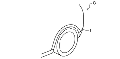
- FIG. 1 shows an example of a resin member 1 according to this embodiment.
- the resin member 1 is, for example, a fender of an automobile C.
- the resin member 1 is not limited to an automobile fender, but may be, for example, an engine cover, bonnet, roof, door, front panel, side panel, rear panel, front body, lift gate, various members, various frames, bumpers, undercovers, instruments.
- Automobiles such as panels, seat frames, door trims and pillar trims, vehicle parts such as motorcycles, landing gear pods, winglets, spoilers, edges, rudders, elevators, failings, ribs and other aircraft parts, personal computers, mobile phones, tablets, audio It is suitable for electric and electronic equipment parts such as housings of air conditioners and lighting equipment.
- FIG. 2 is an enlarged schematic view of a part of the surface of the fender shown in FIG.
- the resin member 1 according to the present embodiment includes a resin base material 2 and a fine concavo-convex pattern 3 formed on the surface of the resin base material 2.
- the resin base material 2 is for forming the skeleton of the resin member 1.
- the resin material of the resin base material 2 is not particularly limited, but for example, a thermoplastic resin material, a thermosetting resin material, a mixture thereof and the like which are illustrated below can be used.
- thermoplastic resin material examples include polypropylene resin, polyethylene resin, polycarbonate resin, polyamide resin, polyester resin, polyarylene sulfide resin, polyphenylene sulfide resin, polyether ketone, polyether ether ketone resin, and polyether ketone.
- examples thereof include ketone resins, polyether sulfone resins, polyimide resins, polyamideimide resins, polyetherimide resins, polysulfone resins and the like.
- thermosetting resin material examples include epoxy resin, vinyl ester resin, phenol resin, polyimide resin, polyurethane resin, urea resin, melamine resin, bismaleimide resin, unsaturated polyester resin and urethane acrylate resin.
- a thermosetting resin material may be used.
- thermoplastic resin materials and / or thermosetting resin materials in addition to a simple substance, a copolymer of one kind of resin material and another resin material, a modified body, a resin material obtained by blending two or more kinds, and the like can be used. it can.
- a mixture of a thermoplastic resin material and a thermosetting resin material is used as the resin material, the compounding ratio thereof may be appropriately determined depending on the type of resin material, moldability, strength of the resin member 1, and the like.
- a coloring material such as a pigment, a dye or a coloring masterbatch may be added to the resin material.
- the resin material is further provided with reinforcing fibers such as carbon fiber, glass fiber, basalt fiber, filler such as talc, and impact resistance.
- a property improving agent, a UV absorber, an additive such as a functional masterbatch, etc. may be contained. These colorants and additives may be added alone or in combination of plural kinds.
- the content of the colorant is a thermosetting resin material or a thermoplastic resin from the viewpoint of securing sufficient moldability and strength while obtaining excellent designability.
- the amount can be 0.5 parts by mass or more and 10 parts by mass or less with respect to 100 parts by mass of the resin material made of the material.
- the content of the additive is, when the additive is a reinforced fiber, For example, it can be 40% by volume or more and 70% by volume or less, and when the additive is other than the reinforcing fiber, it can be 5% by weight or less, for example.
- the L * -80 ° of the resin base material 2 in the state where the fine concavo-convex pattern 3 is not formed on the surface, which is obtained in the optical characteristic measurement test described later, is preferably less than 6, and more preferably less than 4. can do. As a result, a sufficient blackness of the shade portion can be ensured, and the resin member 1 having an excellent appearance with excellent contrast between the highlight portion and the shade portion can be provided.
- the resin member 1 according to the present embodiment is characterized in that the surface thereof is provided with the fine concavo-convex pattern 3.
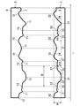
- the lower side of FIG. 3 shows an example of an arbitrary cross section K in a direction perpendicular to a reference plane P described later.
- the fine concavo-convex pattern 3 formed on the surface of the resin base material 2 is for enhancing the designability of the resin member 1.
- a plurality of concave portions 31 and a plurality of concave portions 31 are provided. It has the convex portions 32 and 33 and the inclined portion 34 formed at the transition portion to the convex portions 32 and 33 adjacent to the concave portion 31.
- the plurality of convex portions 32 and 33 include a plurality of first convex portions 32 and a plurality of second convex portions 33, as shown in the lower side of FIG.
- the first convex portion 32 and the second convex portion 33 may be collectively referred to as the convex portions 32 and 33.
- the “height of the fine concavo-convex pattern” is indicated by a symbol H, and, for example, as shown in FIGS. 2 and 3, among the deepest bottom points included in the fine concavo-convex pattern 3 per unit area.
- the reference plane P at an arbitrary point Q on the fine concavo-convex pattern 3 when a plane passing through the three bottom points 31a, 31b, 31c that are not located on a straight line passing through the other two points is set as the reference plane P.
- the “height difference of the fine concavo-convex pattern” means a difference in height H at any two points on the fine concavo-convex pattern 3.
- the “distance of the fine concavo-convex pattern” is indicated by a symbol L, for example, as shown in FIG. 3, and indicates a direction parallel to the reference plane P between any two points on the fine concavo-convex pattern 3.
- the length in particular, in the surface shape profile of the fine concavo-convex pattern 3 obtained in the surface shape observation test described later, it means the length in the direction parallel to the reference plane P from the measurement start position to a predetermined position on the fine concavo-convex pattern 3. There is.
- the height H1 of the first convex portion 32 corresponds to the maximum height difference of the fine concavo-convex pattern 3, and is 15 ⁇ m or more and 35 ⁇ m or less, preferably 15 ⁇ m or more and 30 ⁇ m or less.
- the height H2 of the second convex portion 33 is 1/4 or more and 3/4 or less, preferably 1/3 or more and 2/3 or less of the height H1 of the first convex portion 32.
- the distance between the vertices in the lengthwise direction of the two protrusions 32 and 33 adjacent to each other among the protrusions 32 and 33 (in the present specification, “pitch D”). May be referred to as)) is 100 ⁇ m or more and 500 ⁇ m or less.
- FIG. 4 is an enlarged schematic view of a portion indicated by reference numeral IV in FIG.
- the minute area s of the minute uneven pattern and "the inclination angle ⁇ of the minute area” are as follows. That is, as shown in FIGS. 3 and 4, in an arbitrary cross section K in the direction perpendicular to the reference plane P of the fine concavo-convex pattern 3, a projection point Q ′ of an arbitrary point Q of the fine concavo-convex pattern on the reference plane P is calculated.
- the area of the fine concavo-convex pattern between the points A and B on the fine concavo-convex pattern having the points A ′ and B ′ which are the midpoints and give the predetermined length d as projection points is called a micro area s, and the points A and B are
- the angle formed by the passing straight line and the reference plane P is referred to as the inclination angle ⁇ (°) of the minute area s.
- the “all minute areas” means all the minute areas s included in the fine uneven pattern 3 per predetermined distance in the cross section K.
- FIG. 5 is a diagram for explaining an angle of reflected light when light is incident on the fine concavo-convex pattern 3 at an incident angle ⁇ , that is, a reflection angle ⁇ .
- the specular reflection contributes to the highlight portion and brings the surface gloss of the resin member 1. Therefore, it is considered that the gloss of the surface of the resin member 1 increases as the proportion of the small area s having a small inclination angle ⁇ increases.
- the number of minute regions s having an inclination angle ⁇ of ⁇ 10 ° or more and 10 ° or less is 78% or more and 95% or less, preferably 90% or more and 95% or less of the number of all the minute regions.
- the number of minute regions s having the inclination angle ⁇ of -1 ° or more and 1 ° or less is 25% or more and 40% or less, preferably 30% or more and 40% or less of the number of all the minute regions.
- the reflection angle ⁇ is 45 ° in the inclined portion 34 formed in the transition portion from the concave portion 31 to the convex portions 32, 33 of the fine concavo-convex pattern 3, for example. More or less than. Then, the reflected light is less likely to be specularly reflected, which causes a decrease in the amount of light that contributes to the highlight portion.
- the convex portions 32 and 33 having the fine concavo-convex pattern are provided with the first convex portion 32 and the second convex portion 33 having a height lower than that of the first convex portion 32.
- the pitch D between 32 and 33 within the above range, it is possible to reduce the proportion of the inclined portion 34 that contributes little to the highlight portion.
- the amount of light in the highlighted portion of the reflected light can be effectively increased, and as described above, the gloss of the surface on which the fine concavo-convex pattern 3 is formed is increased and a clear shadow is generated.
- L * value at the light-receiving angle ⁇ 45 °, which indicates the amount of specular reflection contributing to the highlight portion of the reflected light of the resin member 1 obtained in the optical characteristic measurement test described later, L * 45 ° is 85 or more 130 It is preferably 110 or more and 130 or less.
- the light receiving angle ⁇ indicates the light receiving angle of the detector used in the optical measurement test described later, and corresponds to the reflection angle ⁇ .
- the average value L * -80 ° to L * -55 ° of the brightness L * value of the reflected light having a light receiving angle of ⁇ 80 ° ⁇ ⁇ ⁇ ⁇ 55 ° that contributes to the blackness of the shade portion is It is 20 or more and 80 or less, preferably 42 or more and 80 or less. As a result, it is possible to obtain a sufficient amount of reflected light in the highlight portion and a sufficient blackness in the shade portion, and it is possible to secure sufficient gloss and clear shadow.
- the resin member 1 according to the present embodiment is manufactured by injection molding using a molding die 5 as shown in the upper diagram of FIG. 3, for example.
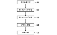
- the method of manufacturing the resin member 1 includes a mold preparing step S1, a first etching step S2, a second etching step S3, an optional blasting step S4, and a molding step. And S5.
- a mold preparing step S1 a first etching step S2, a second etching step S3, an optional blasting step S4, and a molding step.
- S5. a molding step.
- the molding die 5 includes a die base material 6 and a grain pattern 7 formed on the surface thereof.
- the mold base material 6 is prepared.
- any metal material used in a general resin material injection molding die can be used, and specifically, for example, a steel material, a zinc alloy, A metal material such as an aluminum alloy can be used. These metal materials are cut to obtain a mold base material 6 for molding the desired shape of the resin member 1.
- a grain pattern 7 for forming the fine concavo-convex pattern 3 of the resin member 1 is formed by the first etching step S2, the second etching step S3, and the blasting step S4.
- the embossed pattern 7 is an inverted pattern of the fine concavo-convex pattern 3 and is transferred to the surface of the resin member 1 in the subsequent molding step S5.
- the first etching step S2 is a step for forming a rough texture pattern on the molding surface of the molding die 5 as a preparatory step for forming the texture pattern 7.
- the first etching step S2 is performed by treating the molding surface of the molding die 5 with an etching solution and then washing the die base material 6 with water or the like.
- the etching liquid for example, a chemical polishing liquid for steel or an iron perchloride liquid is used alone, or a mixture of water, nitric acid, hydrochloric acid and the like is used.
- the blending components and blending ratio of the etching liquid, and the etching treatment time are appropriately determined according to the material of the die substrate 6 to be etched, the desired height H of the fine concavo-convex pattern 3, the desired pitch D, and the like. ..
- the second etching step S3 is a step for forming a finer texture pattern by further etching the molding surface on which the rough texture pattern is formed in the first etching step S2.
- the procedure of the second etching step S3 is the same as that of the first etching step S2, and is performed by treating the molding surface with an etching solution and then washing the mold with water or the like.
- the etching solution the same etching solution as in the first etching step S2 can be used, and the same etching solution as in the first etching step S2 may be used, or a different etching solution may be used.
- the mixing ratio may be the same or different.
- the composition of the etching solution, the composition ratio, and the etching treatment time are the same as in the first etching step S2, the material of the die base material 6 to be etched, the desired height H of the fine uneven pattern 3, and the desired pitch. It is appropriately determined according to D and the like.
- the blasting step S4 is a step of performing a blasting process on the molding surface of the die base material 6 after the second etching step S3 to obtain the grain pattern 7.
- the convex portion 71 of the embossed pattern 7 the first concave portion 72 having a different height, and the second concave portion 73 are transferred to the surface of the resin member 1, the concave portion 31 and the first concave portion 31 of the fine concave-convex pattern 3 respectively. It is a shape that brings the convex portion 32 and the second convex portion 33.
- the blasting treatment include bead blasting and sand blasting. From the viewpoint of obtaining the embossed pattern 7 that gives the desired fine relief pattern 3, for example, the bead blasting treatment using glass beads having an average particle diameter D50 of about 50 ⁇ m to 300 ⁇ m is adopted. It is desirable to do.
- the molding die 5 is set in an injection molding device equipped with a fixed mold and a movable mold, and a resin material is injected into a cavity formed by a molding surface to perform molding.
- injection molding conditions general conditions used in injection molding of resin materials can be adopted, and can be appropriately changed depending on the resin material. After the resin material injected into the cavity is solidified, the molding die is released to obtain the resin member 1.
- FIG. 7 is a view corresponding to FIG. 3 showing the fine concavo-convex pattern 3 of the resin member 1 according to the second embodiment. From the surface shape observation test and the examination of the reflection intensity described later, the fine concavo-convex pattern 3 is 90 ⁇ m or more, preferably 90 ⁇ m or more in the direction parallel to the reference plane P in the cross section K perpendicular to the reference plane P as shown in FIG.
- the incident light can be specularly reflected on the flat portion 35 having a length of 90 ⁇ m or more, so that the reflected light can be clearly recognized by the human visual sense.
- the flat portion 35 may be formed on either the concave portion 31 or the convex portions 32 and 33 as shown in FIG. 7.
- the pitch D can be calculated with the apex of the convex portions 32 and 33 as the center of the flat portion 35, as shown in the lower section of FIG. 4. ..
- the molding surface is polished with an abrasive material such as a buff cloth.
- an abrasive material such as a buff cloth.
- the resin member 1 is manufactured by injection molding, but the method for manufacturing the resin member 1 is not limited to injection molding, and for example, extrusion molding, vacuum molding, blow molding, Methods such as injection compression molding, decorative molding, gas-assisted injection molding, foam injection molding, low pressure molding, ultra-thin wall injection molding (ultra high-speed injection molding), in-mold composite molding (insert molding, outsert molding), For example, a method of forming a precursor sheet in which sheets of resin material are laminated by press molding or the like can be mentioned. From the viewpoint of production stability, economy, etc., injection molding, injection compression molding, and a molding method combining these with in-mold composite molding are preferable.
- a commercially available steel material was cut as the die base material 6. Then, the molding surface of the die base material 6 was immersed in a mixed solution of water, nitric acid and hydrochloric acid for 15 minutes in the ambient temperature atmosphere to perform the first etching treatment. Then, the mold base material 6 was washed with water. Then, it was further immersed in the above mixed solution for 10 minutes to perform a second etching treatment. Then, the mold base material 6 was washed with water. Then, the molding surface was subjected to a bead blast treatment using glass beads having an average particle diameter D50 of about 100 ⁇ m. Thus, a molding die 5 having a textured pattern 7 on the molding surface was obtained.
- ⁇ Manufacture of resin test pieces As a resin material, 98 parts by mass of a polypropylene resin (manufactured by Nippon Polypro Co., Ltd., BXZ04G) and 2 parts by mass of a colored masterbatch (manufactured by DIC Co., Ltd., F-30940MM BLACK) were used, and the molding die 5 was set 180. Using a ton injection molding device (manufactured by FANUC CORPORATION), molding was performed to obtain a resin test piece 11.
- a polypropylene resin manufactured by Nippon Polypro Co., Ltd., BXZ04G
- a colored masterbatch manufactured by DIC Co., Ltd., F-30940MM BLACK
- Example 2 A resin test piece was obtained in the same procedure as in Example 1 except that the first etching treatment time was 30 minutes and the second etching treatment time was 20 minutes.
- Example 3 A resin test piece was obtained in the same procedure as in Example 2 except that the molding surface of the die base material obtained after the second etching was polished with a buff cloth for 5 minutes.
- Example 4 Same as Example 2 except that PPCM917Y-95 BLACK 30X manufactured by Tokyo Ink Co., Ltd. was used as a coloring masterbatch, and the molding surface of the mold base material obtained after the second etching was polished with a buff cloth for 5 minutes. A resin test piece was obtained by the procedure.
- Table 1 shows various test results of the resin test pieces of Examples 1 to 4 and Comparative Examples 1 to 3.
- the inclination angle ⁇ is ⁇ 10 ° or more and 10 ° or less, and ⁇ 1 ° or more and 1 ° with respect to the number of the minute regions s (the number of all the minute regions) per predetermined distance 2500 ⁇ m.
- the ratio of the number of the following minute regions s was calculated.
- the reflection intensity I R in each minute region s was calculated using the following formula (1).
- I R (F ( ⁇ ) ⁇ n ⁇ l) / I 0 (1)
- ⁇ is the above-mentioned incident angle
- F ( ⁇ ) is the Fresnel reflectance
- n is the number of minute regions
- l is the length of the minute region s, that is, the length of the line segment AB in FIG. 4, for example.
- I 0 is the reflection intensity of the resin base material 2.
- FIG. 17 shows an example of the integrated result of the reflection intensities I R of Example 4.
- the position No. that maximizes the integrated value of the reflection intensity I R is considered.
- the area is the area in which the flat portion 35 is formed
- the number of such flat portions 35 included in the predetermined distance 2500 ⁇ m is calculated, and the average value of the three visual fields is shown in Table 1 as described above. It was calculated as the number of flat portions (pieces / 2500 ⁇ m). Then, the predetermined distance 2500 ⁇ m was divided by the calculated number of flat portions 35 to calculate the distance ( ⁇ m / piece) per flat portion.
- ⁇ Optical property measurement test> The L * value was measured using a goniospectrophotometer (manufactured by Murakami Color Research Laboratory Co., Ltd., three-dimensional goniospectroscopic system GCMS-4). The incident angle ⁇ was 45 °, and the light receiving angle ⁇ which was the light receiving angle of the detector for reflected light was ⁇ 80 ° to 80 ° (in steps of 5 °). The measurement results are shown in FIG. 18 and Table 1.
- Each of L * 55 ° -L * 75 ° represents the amount of reflected light in the vicinity of regular reflection.
- the average value L * -80 ° to L * -55 ° of the lightness L * value of the reflected light having the acceptance angle of ⁇ 80 ° ⁇ ⁇ ⁇ ⁇ 55 ° contributes to the blackness of the shade portion of the reflected light.
- the L * -80 ° of the resin base material was the resin test piece 11 shown in FIG. 11, and the optical property measurement test was performed on the test piece in which the fine concavo-convex pattern 3 was not formed on the surface 12. The results obtained.
- ⁇ Visual observation test> Three testers (two men, one woman, 30 to 50 years old, corrected visual acuity eyes 0.5 or more) observe the surface of the resin test piece with their eyes separated by 30 cm. It was The three evaluation items were (1) gloss as a macro texture, (2) shade blackness, and (3) graininess as a micro texture. For each of the evaluation items (1) to (3), each tester performed a five-level evaluation of "5 ... very good, 4 ... good, 3 ... normal, 2 ... bad, 1 ... very bad". .. Then, from the average value of the evaluation results of all the testers, observation results were obtained as A ... 4 or more and 5 or less, B ... 3 or more and 4 or less, C ... 2 or more and 3 or less, D ... 2 or less.
- the evaluation result of D was obtained in two or more items in all the test pieces.
- the resin test pieces of Examples 1 to 4 were found to be generally excellent in both the macro texture and the micro texture, although the resin test pieces of Example 1 had a slightly insufficient graininess.
- the present disclosure can provide a resin member having a sufficient gloss and shadow on the surface and having an excellent appearance design property, a molding die for the resin member, and a method for manufacturing the resin member, which is extremely useful. Is.
Landscapes
- Engineering & Computer Science (AREA)
- Mechanical Engineering (AREA)
- Manufacturing & Machinery (AREA)
- Moulds For Moulding Plastics Or The Like (AREA)
- Shaping Of Tube Ends By Bending Or Straightening (AREA)
Abstract
樹脂製基材と、前記樹脂製基材の表面に形成され、複数の凹部及び複数の凸部からなる微細凹凸模様とを備えた樹脂製部材であって、前記複数の凸部は、高さが15μm以上35μm以下の複数の第1凸部と、高さが前記第1凸部の高さの1/4以上3/4以下である複数の第2凸部とを備えており、前記複数の凸部のうち、互いに隣り合う2つの前記凸部の頂点間距離は、100μm以上500μm以下であり、単位面積当たりの前記微細凹凸模様に含まれる最も高さの低い任意の3つの最底点を通る平面を基準面とし、前記基準面に垂直な断面において、所定距離当たりの前記微細凹凸模様を所定長さの微小領域に分割したときに、該微小領域の前記基準面に対する傾斜角度が-10°以上10°以下である該微小領域の数は、所定距離当たりの前記微細凹凸模様に含まれる全微小領域の数の78%以上95%以下であり、前記傾斜角度が-1°以上1°以下である前記微小領域の数は、前記全微小領域の数の25%以上40%以下であることを特徴とする。
Description
本開示は、樹脂製部材、樹脂製部材の成形用金型及び樹脂製部材の製造方法に関するものである。
従来より、樹脂製部材の表面に微細な凹凸模様を施して外観の意匠性を向上させることが行われている(例えば、特許文献1参照)。
特許文献1には、低グロスが求められる部分におけるグロス値を効果的に低減することができる樹脂製部材として、多数の微小凸部が配列された低グロス部を備え、前記多数の微小凸部の配列ピッチが、該微小凸部の根元径に対して50%以上100%以下である樹脂製部材が開示されている。
ところで、樹脂製部材の表面に施された微細凹凸模様について、高さや隣り合う凸部間のピッチが増大しすぎると、凸部と凹部とを繋ぐ側面が大きくなり得る。そうすると、当該側面によって反射される光の量が増加し、微細凹凸模様により反射される光の高輝度のハイライト部分と低輝度のシェード部分との輝度差が減少し得る。そうして、表面の光沢及び陰影が不足し、樹脂製部材の外観の意匠性が低下するという問題があった。
そこで本開示は、表面に十分な光沢及び陰影を有し、外観の意匠性に優れた樹脂製部材、樹脂製部材の成形用金型及び樹脂製部材の製造方法をもたらすことを課題とする。
上記の課題を解決するために、ここに開示する樹脂製部材は、樹脂製基材と、前記樹脂製基材の表面に形成され、複数の凹部及び複数の凸部からなる微細凹凸模様とを備えた樹脂製部材であって、単位面積当たりの前記微細凹凸模様に含まれる最も深い任意の3つの最底点を通る平面を基準面とし、該微細凹凸模様上の任意の点における該基準面からの最短距離を該微細凹凸模様の高さとしたときに、前記複数の凸部は、高さが15μm以上35μm以下の複数の第1凸部と、高さが前記第1凸部の高さの1/4以上3/4以下である複数の第2凸部とを備えており、前記複数の凸部のうち、互いに隣り合う2つの前記凸部の頂点間距離は、100μm以上500μm以下であり、前記基準面に垂直な断面において、所定距離当たりの前記微細凹凸模様を所定長さの微小領域に分割したときに、該微小領域の前記基準面に対する傾斜角度が-10°以上10°以下である該微小領域の数は、所定距離当たりの前記微細凹凸模様に含まれる全微小領域の数の78%以上95%以下であり、前記傾斜角度が-1°以上1°以下である前記微小領域の数は、前記全微小領域の数の25%以上40%以下であることを特徴とする。
微細凹凸模様に対して光が入射角45°で入射すると、平らな部分では入射角45°で入射し反射角45°で反射される正反射が増加し、ハイライト部分が増加する。一方、微細凹凸模様の例えば凹部から凸部への移行部に形成される傾斜面では、光は正反射となり難く、ハイライト部分に寄与し難い。ここに、微細凹凸模様の凹部と凸部の最大高低差、すなわち高さが大きく、隣り合う2つの凸部の頂点間距離が大きくなると、凸部の頂点から凹部にかけて形成される傾斜面の割合が増加する。そうすると、傾斜面による反射光が増加し、微細凹凸模様による反射光のうちハイライト部分が減少し、光沢が低下するとともに、ハイライト部分とシェード部分とのコントラストが減少して、陰影が低下し得る。
本技術によれば、微細凹凸模様の凸部について、第1凸部と、第1凸部よりも高さの小さい第2凸部を設け、凸部間のピッチを上記範囲とすることにより、傾斜面の割合を低下させることができる。そうすると、反射光のうちハイライト部分の割合が増加し、微細凹凸模様が形成された表面の光沢が増加するとともに、ハイライト部分とシェード部分とのコントラストが増加して、より明瞭な陰影をもたらすことができる。そうして、樹脂製部材の外観の意匠性を向上させることができる。
好ましくは、前記基準面に垂直な断面において、前記微細凹凸模様は、前記基準面と平行な方向に90μm以上の長さを有する平坦部を、長さ300μm以上500μm以下の範囲内に1個の割合で有することを特徴とする。
人の網膜からの距離30cmにおける視覚空間分解能を約90μmとすると、例えば90μm以上の長さを有する平坦部では、入射光が正反射され得るため、人の視覚において反射光を明瞭に認識することができる。本技術によれば、平坦部の数を上記割合で形成することにより、人の視覚において、一定の割合で高い光沢をもたらす部分が現れるため、微細凹凸模様の粒子感を高めることができ、樹脂製部材の外観の意匠性を向上させることができる。
好ましくは、設定値よりも短波長成分を除去する低域フィルタの該設定値をカットオフ値λsとし、設定値よりも高波長成分を除去する高域フィルタの該設定値をカットオフ値λcとしたときに、前記微細凹凸模様が形成された表面の、前記カットオフ値λs=2.5μm及び前記カットオフ値λc=80μmにおける算術平均粗さRaは、0.2μm以上0.4μm以下であることを特徴とする。
微細凹凸模様の表面には、凹部及び凸部よりも微細な凹凸が形成され得る。本技術によれば、微細凹凸模様表面のより微細な凹凸について、表面粗さを上記範囲とすることにより、ハイライト部分に寄与する反射光強度を高めて、より高い光沢や粒子感を備えた樹脂製部材をもたらすことができる。
好ましくは、入射角45°で変角分光光度計を用いて測定された受光角γの明度をL*値としたときに、受光角γ=45°の明度L*
45°は85以上130以下であり、前記明度L*
45°と、受光角γ=20°の明度L*
20°との差であるL*
45°-L*
20°は48以上104以下であることを特徴とする。
本技術によれば、優れた光沢及び陰影を有し、意匠性に優れた外観を備えた樹脂製部材をもたらすことができる。
好ましくは、入射角45°で変角分光光度計を用いて測定された受光角γの明度をL*値としたときに、前記微細凹凸模様が形成されていない前記樹脂製基材における、受光角γ=-80°の明度L*
-80°は6未満であることを特徴とする。
本技術によれば、シェード部分の十分な黒さを確保し、ハイライト部分とシェード部分とのコントラストに優れ、意匠性に優れた外観を備えた樹脂製部材をもたらすことができる。
また、ここに開示する成形用金型は、上述の樹脂製部材を製造するための成形用金型である。
本技術によれば、意匠性に優れた外観を備えた樹脂製部材をもたらすことができる。
また、ここに開示する樹脂製部材の製造方法は、上述の成形用金型を用いて射出成形により前記樹脂製部材を製造することを特徴とする。
本技術によれば、意匠性に優れた外観を備えた樹脂製部材をもたらすことができる。
以上述べたように、本開示によると、微細凹凸模様の凸部について、第1凸部と、第1凸部よりも高さの小さい第2凸部を設け、凸部間のピッチを上記範囲とすることにより、傾斜面の割合を低下させることができる。そうすると、反射光のうちハイライト部分の割合が増加し、微細凹凸模様が形成された表面の光沢が増加するとともに、ハイライト部分とシェード部分とのコントラストが増加して、より明瞭な陰影をもたらすことができ、樹脂製部材の外観の意匠性を向上させることができる。
以下、本開示の実施形態を図面に基づいて詳細に説明する。以下の好ましい実施形態の説明は、本質的に例示に過ぎず、本開示、その適用物或いはその用途を制限することを意図するものでは全くない。
(実施形態1)
<樹脂製部材>
図1は、本実施形態に係る樹脂製部材1の一例を示している。樹脂製部材1は、例えば自動車Cのフェンダである。樹脂製部材1は、自動車のフェンダに限らず、例えばエンジンカバー、ボンネット、ルーフ、ドア、フロントパネル、サイドパネル、リアパネル、フロントボディ、リフトゲート、各種メンバ、各種フレーム、バンパー、アンダーカバー、インストルメントパネル、シートフレーム、ドアトリム、ピラートリム等の自動車、二輪車等車両部品、ランディングギアポッド、ウィングレット、スポイラー、エッジ、ラダー、エレベーター、フェイリング、リブ等の航空機用部品、パソコン、携帯電話、タブレット、オーディオ、エアコン、照明機器の筐体等の電気、電子機器部品等に好適である。
図2は、図1のフェンダの表面の一部を拡大して模式的に示す図である。本実施形態に係る樹脂製部材1は、図2に示すように、樹脂製基材2と、樹脂製基材2の表面に形成された微細凹凸模様3とを備えている。
≪樹脂製基材≫
樹脂製基材2は、樹脂製部材1の骨格を形成するためのものである。
樹脂製基材2は、樹脂製部材1の骨格を形成するためのものである。
樹脂製基材2の樹脂材料としては、特に限定されるものではないが、例えば以下に例示する熱可塑性樹脂材料、熱硬化性樹脂材料、及びこれらの混合物等を用いることができる。
熱可塑性樹脂材料としては、具体的には例えば、ポリプロピレン樹脂、ポリエチレン樹脂、ポリカーボネート樹脂、ポリアミド樹脂、ポリエステル樹脂、ポリアリーレンスルフィド樹脂、ポリフェニレンスルフィド樹脂、ポリエーテルケトン、ポリエーテルエーテルケトン樹脂、ポリエーテルケトンケトン樹脂、ポリエーテルスルホン樹脂、ポリイミド樹脂、ポリアミドイミド樹脂、ポリエーテルイミド樹脂、ポリスルホン樹脂等が挙げられる。
熱硬化性樹脂材料としては、具体的には例えば、エポキシ樹脂、ビニルエステル樹脂、フェノール樹脂、ポリイミド樹脂、ポリウレタン樹脂、ユリア樹脂、メラミン樹脂、ビスマレイミド樹脂、不飽和ポリエステル樹脂、ウレタンアクリレート樹脂等の熱硬化性樹脂材料が挙げられる。
これらの熱可塑性樹脂材料及び/又は熱硬化性樹脂材料は、単体の他、一種の樹脂材料と他の樹脂材料との共重合体、変性体および2種類以上ブレンドした樹脂材料等も用いることができる。樹脂材料として、熱可塑性樹脂材料と熱硬化性樹脂材料との混合物を用いる場合、これらの配合比は、樹脂材料の種類、成形性、樹脂製部材1の強度等に応じて適宜決定され得る。
なお、樹脂製部材1に着色を施すために、樹脂材料に、顔料、染料、着色マスターバッチ等の着色材を添加してもよい。また、樹脂製部材1の成形性、強度、意匠性、機能性等の向上の観点から、樹脂材料に、さらに、炭素繊維、ガラスファイバ、バサルトファイバ等の強化繊維、タルク等のフィラー、耐衝撃性改良剤、UV吸収剤、機能性マスターバッチ等の添加材等を含有させてもよい。これらの着色材や添加材は単独で添加してもよいし、複数種を添加してもよい。
樹脂製部材1中に着色材を含有させる場合には、着色材の配合量は、優れた意匠性を得つつ十分な成形性及び強度を確保する観点から、熱硬化性樹脂材料及び熱可塑性樹脂材料からなる樹脂材料100質量部に対して、例えば0.5質量部以上10質量部以下とすることができる。
樹脂製部材1中に、添加材等を含有させる場合には、成形性、強度、意匠性、機能性等を向上させる観点から、添加材の含有量は、添加材が強化繊維の場合は、例えば40体積%以上70体積%以下、添加材が強化繊維以外の場合は、例えば5質量%以下とすることができる。
-樹脂製基材の光学特性-
なお、後述する光学特性測定試験において得られる、表面に微細凹凸模様3が形成されていない状態での樹脂製基材2のL* -80°は、好ましくは6未満、より好ましくは4未満とすることができる。これにより、シェード部分の十分な黒さを確保し、ハイライト部分とシェード部分とのコントラストに優れ、意匠性に優れた外観を備えた樹脂製部材1をもたらすことができる。
なお、後述する光学特性測定試験において得られる、表面に微細凹凸模様3が形成されていない状態での樹脂製基材2のL* -80°は、好ましくは6未満、より好ましくは4未満とすることができる。これにより、シェード部分の十分な黒さを確保し、ハイライト部分とシェード部分とのコントラストに優れ、意匠性に優れた外観を備えた樹脂製部材1をもたらすことができる。
≪微細凹凸模様≫
ここに、本実施形態に係る樹脂製部材1は、その表面に微細凹凸模様3を備えていることを特徴とする。なお、図3の下側の図は、後述する基準面Pに垂直な方向における任意の断面Kの一例を示している。
ここに、本実施形態に係る樹脂製部材1は、その表面に微細凹凸模様3を備えていることを特徴とする。なお、図3の下側の図は、後述する基準面Pに垂直な方向における任意の断面Kの一例を示している。
樹脂製基材2の表面に形成された微細凹凸模様3は、樹脂製部材1の意匠性を高めるためのものであり、図2,図3に示すように、複数の凹部31と、複数の凸部32,33と、凹部31と隣り合う凸部32,33への移行部に形成された傾斜部34とを有している。
複数の凸部32,33は、図3の下側の図に示すように、複数の第1凸部32と複数の第2凸部33とを備えている。なお、本明細書において、第1凸部32及び第2凸部33をまとめて凸部32,33と称することがある。
-微細凹凸模様の高さ及び距離-
本明細書において、「微細凹凸模様の高さ」とは、符号Hで示し、例えば図2,図3に示すように、単位面積当たりの微細凹凸模様3に含まれる最も深い最底点のうち、互いに他の2点を通る直線上に位置しない3つの最底点31a,31b,31cを通る平面を基準面Pとしたときに、微細凹凸模様3上の任意の点Qにおける基準面Pからの最短距離、すなわち基準面Pの法線ベクトルNp方向の基準面Pからの直線距離を意味する。そして、「微細凹凸模様の高低差」とは、微細凹凸模様3上の任意の2点における高さHの差を意味する。
本明細書において、「微細凹凸模様の高さ」とは、符号Hで示し、例えば図2,図3に示すように、単位面積当たりの微細凹凸模様3に含まれる最も深い最底点のうち、互いに他の2点を通る直線上に位置しない3つの最底点31a,31b,31cを通る平面を基準面Pとしたときに、微細凹凸模様3上の任意の点Qにおける基準面Pからの最短距離、すなわち基準面Pの法線ベクトルNp方向の基準面Pからの直線距離を意味する。そして、「微細凹凸模様の高低差」とは、微細凹凸模様3上の任意の2点における高さHの差を意味する。
また、本明細書において、「微細凹凸模様の距離」とは、例えば図3に示すように、符号Lで示し、微細凹凸模様3上の任意の二点間の基準面Pに平行な方向の長さをいう。特に、後述する表面形状観察試験において得られた微細凹凸模様3の表面形状プロファイルでは、測定開始位置から微細凹凸模様3上の所定の位置までの基準面Pに平行な方向の長さをいうことがある。
第1凸部32の高さH1は、微細凹凸模様3の最大高低差に相当し、15μm以上35μm以下、好ましくは15μm以上30μm以下である。そして、第2凸部33の高さH2は、第1凸部32の高さH1の1/4以上3/4以下、好ましくは1/3以上2/3以下である。
また、図3の下側の図に示すように、凸部32,33のうち、互いに隣り合う2つの凸部32,33の長さ方向の頂点間距離(本明細書において、「ピッチD」と称することがある。)は、100μm以上500μm以下である。
-微小領域の傾斜角度-
図4は、図3の符号IVで示す部分を拡大して示す模式図である。
図4は、図3の符号IVで示す部分を拡大して示す模式図である。
本明細書において、「微細凹凸模様の微小領域s」及び「微小領域の傾斜角度θ」は、以下の通りとする。すなわち、図3,図4に示すように、微細凹凸模様3の基準面Pに垂直な方向における任意の断面Kにおいて、微細凹凸模様の任意の点Qの基準面Pへの投影点Q’を中点とし且つ所定の長さdを与える点A’,B’を投影点とする微細凹凸模様上の点A,B間の微細凹凸模様の領域を微小領域sといい、点A,Bを通る直線と基準面Pとのなす角を微小領域sの傾斜角度θ(°)という。
そして、「全微小領域」とは、断面Kにおける所定距離当たりの微細凹凸模様3に含まれる全ての微小領域sをいう。
-微細凹凸模様に照射される光の反射角について-
図5は、微細凹凸模様3に入射角αで光が入射したときの反射光の角度、すなわち反射角βについて説明するための図である。なお、入射角α及び反射角βは、図5に示すように、基準面Pの法線ベクトルNpに対する角度として与えられる。そして、反射角βは、基準面Pに対する傾斜角度θを用いて、β=α+2θで表すことができる。
図5は、微細凹凸模様3に入射角αで光が入射したときの反射光の角度、すなわち反射角βについて説明するための図である。なお、入射角α及び反射角βは、図5に示すように、基準面Pの法線ベクトルNpに対する角度として与えられる。そして、反射角βは、基準面Pに対する傾斜角度θを用いて、β=α+2θで表すことができる。
具体的には、例えば微小領域s1では、基準面Pに対する傾斜角度θは0°であるので、入射角αで入射した光は、反射角β=α+2θ=αで正反射する。すなわち例えば、入射角α=45°であれば反射角β=45°となる。また、微小領域s2では、基準面Pに対する傾斜角度θはθ>0°であるから、反射角βは、β=α+2θ=α+2|θ|で表される。また、微小領域s3では、基準面Pに対する傾斜角度θはθ<0°であるから、反射角βは、β=α+2θ=α-2|θ|で表される。
反射光のうち、上記正反射は、ハイライト部分に寄与し、樹脂製部材1の表面の光沢をもたらす。従って、傾斜角度θが小さい微小領域sの割合が増加すると、樹脂製部材1の表面の光沢が増加すると考えられる。
すなわち、傾斜角度θが-10°以上10°以下である微小領域sの数は、全微小領域の数の78%以上95%以下、好ましくは90%以上95%以下である。そして、傾斜角度θが-1°以上1°以下である微小領域sの数は、全微小領域の数の25%以上40%以下、好ましくは30%以上40%以下である。これにより、反射光のうち、ハイライト部分の割合を増加させることができ、微細凹凸模様3が形成された表面の光沢を増加させることができる。また、ハイライト部分の割合が増加することにより、ハイライト部分とシェード部分とのコントラストが増加して、より明瞭な陰影をもたらすことができる。そうして、樹脂製部材1の外観の意匠性を向上させることができる。
なお、図5の微小領域s2,s3の図に示すように、微細凹凸模様3の例えば凹部31から凸部32,33への移行部に形成される傾斜部34では、反射角βは45°よりも増大又は減少する。そうすると、反射光は正反射とはなり難く、ハイライト部分に寄与する光の量が低下する原因となる。
本実施形態に係る樹脂製部材1では、微細凹凸模様の凸部32,33について、第1凸部32と、第1凸部32よりも高さの低い第2凸部33を設け、凸部32,33間のピッチDを上記範囲とすることにより、ハイライト部分への寄与が少ない傾斜部34の割合を低減させることができる。そうして、反射光のうちのハイライト部分の光の量を効果的に増加させることができ、上述のごとく、微細凹凸模様3が形成された表面の光沢を増加させるとともに、明瞭な陰影を得ることができ、樹脂製部材1の外観の意匠性を向上させることができる。
≪樹脂製部材の光学特性≫
後述する光学特性測定試験において得られる、樹脂製部材1の反射光のハイライト部分に寄与する正反射の量を示す受光角γ=45°の明度L*値、L* 45°は85以上130以下、好ましくは110以上130以下である。なお、受光角γは、後述する光学測定試験において使用される検出器の受光角度を示しており、反射角βに相当する。また、正反射近傍の反射光の量を示す受光角γ=45°と受光角γ=20°の明度L*値の差L* 45°-L* 20°は47以上96以下、好ましくは77以上96以下である。さらに、正反射近傍の反射光の量を示す受光角γ=55°と受光角γ=75°の明度L*値の差L* 55°-L* 75°は7.5未満、好ましくは5未満である。また、反射光のうち、シェード部分の黒さに寄与する受光角-80°≦γ≦-55°の反射光の明度L*値の平均値L* -80°~L* -55°は、20以上80以下、好ましくは42以上80以下である。これにより、ハイライト部分の反射光の十分な量及びシェード部分の十分な黒さを得ることができ、十分な光沢及び明瞭な陰影を確保することができる。
後述する光学特性測定試験において得られる、樹脂製部材1の反射光のハイライト部分に寄与する正反射の量を示す受光角γ=45°の明度L*値、L* 45°は85以上130以下、好ましくは110以上130以下である。なお、受光角γは、後述する光学測定試験において使用される検出器の受光角度を示しており、反射角βに相当する。また、正反射近傍の反射光の量を示す受光角γ=45°と受光角γ=20°の明度L*値の差L* 45°-L* 20°は47以上96以下、好ましくは77以上96以下である。さらに、正反射近傍の反射光の量を示す受光角γ=55°と受光角γ=75°の明度L*値の差L* 55°-L* 75°は7.5未満、好ましくは5未満である。また、反射光のうち、シェード部分の黒さに寄与する受光角-80°≦γ≦-55°の反射光の明度L*値の平均値L* -80°~L* -55°は、20以上80以下、好ましくは42以上80以下である。これにより、ハイライト部分の反射光の十分な量及びシェード部分の十分な黒さを得ることができ、十分な光沢及び明瞭な陰影を確保することができる。
<樹脂製部材の製造方法>
本実施形態に係る樹脂製部材1は、例えば図3の上側の図で示すような成形用金型5を用いて、射出成形により製造される。
本実施形態に係る樹脂製部材1は、例えば図3の上側の図で示すような成形用金型5を用いて、射出成形により製造される。
樹脂製部材1の製造方法は、具体的には図6に示すように、金型準備工程S1と、第1エッチング工程S2と、第2エッチング工程S3と、任意のブラスト工程S4と、成形工程S5とを備える。以下、各工程について説明する。
≪金型準備工程S1≫
成形用金型5は、金型基材6と、その表面に形成されたシボ模様7とを備えている。金型準備工程S1では、金型基材6を準備する。
成形用金型5は、金型基材6と、その表面に形成されたシボ模様7とを備えている。金型準備工程S1では、金型基材6を準備する。
成形用金型5の金型基材6は、一般的な樹脂材の射出成形用金型に用いられる金属材料であればいかなるものも用いることができ、具体的には例えば鋼材、亜鉛合金、アルミニウム合金等の金属材料を挙げることができる。これらの金属材料を切削して、所望の樹脂製部材1の形状を成形するための金型基材6を得る。
≪第1エッチング工程S2≫
金型基材6の成形面には、第1エッチング工程S2、第2エッチング工程S3及びブラスト工程S4により、樹脂製部材1の微細凹凸模様3を形成するためのシボ模様7が形成される。当該シボ模様7は、微細凹凸模様3の反転模様であり、後の成形工程S5により、樹脂製部材1の表面に転写される。
金型基材6の成形面には、第1エッチング工程S2、第2エッチング工程S3及びブラスト工程S4により、樹脂製部材1の微細凹凸模様3を形成するためのシボ模様7が形成される。当該シボ模様7は、微細凹凸模様3の反転模様であり、後の成形工程S5により、樹脂製部材1の表面に転写される。
第1エッチング工程S2は、成形用金型5の成形面に、上記シボ模様7を形成する準備段階として、粗いシボ模様を形成するための工程である。第1エッチング工程S2は、成形用金型5の成形面をエッチング液で処理した後、水等で金型基材6を洗浄することにより行われる。エッチング液としては、例えば鉄鋼用化学研磨液や過塩化鉄液を単独で、または、水、硝酸、塩酸等を配合したものが用いられる。エッチング液の配合成分や配合割合、エッチング処理時間は、エッチングの対象となる金型基材6の材質、微細凹凸模様3の所望の高さH、所望のピッチD等に応じて適宜決定される。
≪第2エッチング工程S3≫
第2エッチング工程S3は、第1エッチング工程S2で粗いシボ模様が形成された成形面に対してさらにエッチングを行うことで、より細かいシボ模様を形成するための工程である。第2エッチング工程S3の手順は、第1エッチング工程S2と同様であり、成形面をエッチング液で処理した後、水等で金型を洗浄することにより行われる。エッチング液は、第1エッチング工程S2と同様のものを用いることができ、第1エッチング工程S2と同一のエッチング液を用いてもよいし、異なるエッチング液を用いてもよい。同一のエッチング液を用いる場合は、同一の配合割合であってもよいし、異なる配合割合であってもよい。エッチング液の配合成分や配合割合、エッチング処理時間は、第1エッチング工程S2と同様に、エッチングの対象となる金型基材6の材質、微細凹凸模様3の所望の高さH、所望のピッチD等に応じて適宜決定される。
第2エッチング工程S3は、第1エッチング工程S2で粗いシボ模様が形成された成形面に対してさらにエッチングを行うことで、より細かいシボ模様を形成するための工程である。第2エッチング工程S3の手順は、第1エッチング工程S2と同様であり、成形面をエッチング液で処理した後、水等で金型を洗浄することにより行われる。エッチング液は、第1エッチング工程S2と同様のものを用いることができ、第1エッチング工程S2と同一のエッチング液を用いてもよいし、異なるエッチング液を用いてもよい。同一のエッチング液を用いる場合は、同一の配合割合であってもよいし、異なる配合割合であってもよい。エッチング液の配合成分や配合割合、エッチング処理時間は、第1エッチング工程S2と同様に、エッチングの対象となる金型基材6の材質、微細凹凸模様3の所望の高さH、所望のピッチD等に応じて適宜決定される。
≪ブラスト工程S4≫
ブラスト工程S4は、第2エッチング工程S3後の金型基材6の成形面に対し、ブラスト処理を行い、シボ模様7を得る工程である。シボ模様7の凸状部71、高さの異なる第1凹状部72、及び第2凹状部73は、樹脂製部材1の表面に転写されると、それぞれ微細凹凸模様3の凹部31、第1凸部32、第2凸部33をもたらす形状である。ブラスト処理は、ビーズブラスト、サンドブラスト等が挙げられるが、所望の微細凹凸模様3を与えるシボ模様7を得る観点から、例えば平均粒径D50が50μm~300μm程度のガラスビーズを用いるビーズブラスト処理を採用することが望ましい。
ブラスト工程S4は、第2エッチング工程S3後の金型基材6の成形面に対し、ブラスト処理を行い、シボ模様7を得る工程である。シボ模様7の凸状部71、高さの異なる第1凹状部72、及び第2凹状部73は、樹脂製部材1の表面に転写されると、それぞれ微細凹凸模様3の凹部31、第1凸部32、第2凸部33をもたらす形状である。ブラスト処理は、ビーズブラスト、サンドブラスト等が挙げられるが、所望の微細凹凸模様3を与えるシボ模様7を得る観点から、例えば平均粒径D50が50μm~300μm程度のガラスビーズを用いるビーズブラスト処理を採用することが望ましい。
≪成形工程S5≫
固定型と可動型を備えた射出成形装置に、上記成形用金型5をセットし、成形面からなるキャビティに樹脂材料を射出して成形を行う。射出成形条件は、樹脂材料の射出成形で用いられる一般的な条件を採用することができ、樹脂材料に応じて適宜変更され得る。キャビティに射出された樹脂材料が固化したのち、成形用金型が離型されることにより、樹脂製部材1が得られる。
固定型と可動型を備えた射出成形装置に、上記成形用金型5をセットし、成形面からなるキャビティに樹脂材料を射出して成形を行う。射出成形条件は、樹脂材料の射出成形で用いられる一般的な条件を採用することができ、樹脂材料に応じて適宜変更され得る。キャビティに射出された樹脂材料が固化したのち、成形用金型が離型されることにより、樹脂製部材1が得られる。
(実施形態2)
以下、本開示に係る他の実施形態について詳述する。なお、これらの実施形態の説明において、実施形態1と同じ部分については同じ符号を付して詳細な説明を省略する。
以下、本開示に係る他の実施形態について詳述する。なお、これらの実施形態の説明において、実施形態1と同じ部分については同じ符号を付して詳細な説明を省略する。
<樹脂製部材>
≪微細凹凸模様≫
図7は、実施形態2に係る樹脂製部材1の微細凹凸模様3を示す図3相当図である。後述する表面形状観察試験及び反射強度の検討から、微細凹凸模様3は、図7に示すように、基準面Pに垂直な方向の断面Kにおいて、基準面Pと平行な方向に90μm以上、好ましくは90μm以上300μm未満の長さを有する平坦部35を、長さ2500μmの範囲内に5個以上8個以下の割合で有する、言い換えると、平均して、長さ300μm以上500μm以下の範囲内に1個の割合で有することが望ましい。
≪微細凹凸模様≫
図7は、実施形態2に係る樹脂製部材1の微細凹凸模様3を示す図3相当図である。後述する表面形状観察試験及び反射強度の検討から、微細凹凸模様3は、図7に示すように、基準面Pに垂直な方向の断面Kにおいて、基準面Pと平行な方向に90μm以上、好ましくは90μm以上300μm未満の長さを有する平坦部35を、長さ2500μmの範囲内に5個以上8個以下の割合で有する、言い換えると、平均して、長さ300μm以上500μm以下の範囲内に1個の割合で有することが望ましい。
人の網膜からの距離30cmにおける視覚空間分解能を約90μmとすると、90μm以上の長さを有する平坦部35では、入射光が正反射され得るため、人の視覚において反射光を明瞭に認識することができる。平坦部35の数を上記割合で形成することにより、人の視覚において、一定の割合で高い光沢をもたらす部分が現れるため、微細凹凸模様の粒子感を高めることができ、樹脂製部材の外観の意匠性を向上させることができる。
なお、平坦部35は、図7に示すように、凹部31及び凸部32,33のいずれに形成されていてもよい。
また、凸部32,33に平坦部35が形成されている場合、図4の下側の断面に示すように、ピッチDは、凸部32,33の頂点を平坦部35の中央として算出できる。
<樹脂製部材の製造方法>
第1エッチング工程S2、第2エッチング工程S3におけるエッチング条件及びブラスト工程S4におけるブラスト条件を適宜調整することにより、上記範囲で平坦部35が形成された微細凹凸模様3を備えた樹脂製部材1を得ることができる。
第1エッチング工程S2、第2エッチング工程S3におけるエッチング条件及びブラスト工程S4におけるブラスト条件を適宜調整することにより、上記範囲で平坦部35が形成された微細凹凸模様3を備えた樹脂製部材1を得ることができる。
(実施形態3)
<樹脂製部材>
≪微細凹凸模様≫
図8及び図9に示すように、微細凹凸模様3の表面には、凹部31及び凸部32,33よりも微小な凹凸形状36が形成され得る。言い換えると、凸部32,33後述する表面形状観察試験において得られる、微細凹凸模様3が形成された表面の、カットオフ値λs=2.5μm及びλc=80μmにおける算術平均粗さRaは、0.2μm以上0.4μm以下、好ましくは0.2μm以上0.25μm以下である構成としてもよい。
<樹脂製部材>
≪微細凹凸模様≫
図8及び図9に示すように、微細凹凸模様3の表面には、凹部31及び凸部32,33よりも微小な凹凸形状36が形成され得る。言い換えると、凸部32,33後述する表面形状観察試験において得られる、微細凹凸模様3が形成された表面の、カットオフ値λs=2.5μm及びλc=80μmにおける算術平均粗さRaは、0.2μm以上0.4μm以下、好ましくは0.2μm以上0.25μm以下である構成としてもよい。
本構成により、微細凹凸模様3表面のより微小な凹凸形状36について、算術平均粗さRaを上記範囲とすることにより、ハイライト部分の反射光強度をさらに高めて、より高い光沢や明瞭な陰影、粒子感を備え、意匠性に優れた外観を備えた樹脂製部材1をもたらすことができる。
<樹脂製部材の製造方法>
第1エッチング工程S2、第2エッチング工程S3におけるエッチング条件及びブラスト工程S4におけるブラスト条件を適宜調整するとともに、図10に示すように、ブラスト工程S4の後に、以下の研磨工程S41を設けることにより、微細凹凸模様3よりも微小な凹凸形状36に対応するシボ模様7の微小なシボ形状76の表面粗さを効果的に低減させて、微小な凹凸形状36の表面粗さを低減させることができる。
≪研磨工程S41≫
具体的には、成形面にシボ模様7が形成された金型基材6について、当該成形面を研磨することにより、シボ模様よりもさらに微小な凹凸形状を低減させる。具体的には、バフ布等の研磨材により成形面を研磨する。これにより、シボ模様の表面に形成された微小な凹凸形状が削られる、シボ模様の表面が滑らかになり、表面粗さが低減する。こうして、最終的な成形用金型が得られる。なお、この研磨工程S41は任意工程であり、必要に応じて設けることができる。
(その他の実施形態)
上記実施形態では、樹脂製部材1は射出成形により製造される構成であったが、樹脂製部材1の製造方法は、射出成形に限られるものではなく、例えば押出成形、真空成形、ブロー成形、射出圧縮成形、加飾成形、ガスアシスト射出成形、発砲射出成形、低圧成形、超薄肉射出成形(超高速射出成形)、金型内複合成形(インサート成形、アウトサート成形)等の方法や、例えば樹脂材料のシートを積層させた前駆体シートをプレス成形等により成形する方法等が挙げられる。なお、生産安定性、経済性等の観点から、射出成形、射出圧縮成形、及びこれらと金型内複合成形とを組み合わせた成形方法が好ましい。
上記実施形態では、樹脂製部材1は射出成形により製造される構成であったが、樹脂製部材1の製造方法は、射出成形に限られるものではなく、例えば押出成形、真空成形、ブロー成形、射出圧縮成形、加飾成形、ガスアシスト射出成形、発砲射出成形、低圧成形、超薄肉射出成形(超高速射出成形)、金型内複合成形(インサート成形、アウトサート成形)等の方法や、例えば樹脂材料のシートを積層させた前駆体シートをプレス成形等により成形する方法等が挙げられる。なお、生産安定性、経済性等の観点から、射出成形、射出圧縮成形、及びこれらと金型内複合成形とを組み合わせた成形方法が好ましい。
樹脂製部材1の表面の一部に微細凹凸模様を形成する場合は、成形用金型の成形面において、シボ模様の形成を所望しない個所に例えば耐食性被膜等を形成することにより、対応することができる。
次に、具体的に実施した実施例について説明する。
(樹脂製試験片)
<実施例1>
≪金型の製造≫
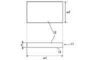
図11に示すように、樹脂製部材1として縦(w1)300mm×横(w2)120mm×厚さ(t)2.5mmの樹脂製試験片11を射出成形により製造するための成形用金型5を準備した。なお、符号12で示す表面に微細凹凸模様3が形成され、裏面13には微細凹凸模様3は形成されない。
<実施例1>
≪金型の製造≫
図11に示すように、樹脂製部材1として縦(w1)300mm×横(w2)120mm×厚さ(t)2.5mmの樹脂製試験片11を射出成形により製造するための成形用金型5を準備した。なお、符号12で示す表面に微細凹凸模様3が形成され、裏面13には微細凹凸模様3は形成されない。
金型基材6として市販の鋼材を切削した。そして、金型基材6の成形面を、常温大気中、水、硝酸及び塩酸の混合液に15分間浸漬して1回目のエッチング処理を行った。そして、金型基材6を水で洗浄した。その後、さらに上記混合液に10分間浸漬して2回目のエッチング処理を行った。そして、金型基材6を水で洗浄した。その後、成形面に対して、平均粒径D50が100μm程度のガラスビーズを用いてビーズブラスト処理を施した。そうして、成形面にシボ模様7が形成された成形用金型5を得た。
≪樹脂製試験片の製造≫
樹脂材料として、ポリプロピレン樹脂(日本ポリプロ株式会社製、BXZ04G)98質量部、着色マスターバッチ(DIC株式会社製、F-30940MM BLACK)2質量部を用い、上記の成形用金型5をセットした180トンの射出成形装置(ファナック株式会社製)を用いて、成形を行い、樹脂製試験片11を得た。
樹脂材料として、ポリプロピレン樹脂(日本ポリプロ株式会社製、BXZ04G)98質量部、着色マスターバッチ(DIC株式会社製、F-30940MM BLACK)2質量部を用い、上記の成形用金型5をセットした180トンの射出成形装置(ファナック株式会社製)を用いて、成形を行い、樹脂製試験片11を得た。
<実施例2>
1回目のエッチング処理時間を30分間、2回目のエッチング処理時間を20分間とした以外は、実施例1と同様の手順で樹脂製試験片を得た。
1回目のエッチング処理時間を30分間、2回目のエッチング処理時間を20分間とした以外は、実施例1と同様の手順で樹脂製試験片を得た。
<実施例3>
2回目のエッチング後に得られた金型基材の成形面をバフ布で5分間研磨した以外は実施例2と同様の手順で樹脂製試験片を得た。
2回目のエッチング後に得られた金型基材の成形面をバフ布で5分間研磨した以外は実施例2と同様の手順で樹脂製試験片を得た。
<実施例4>
着色マスターバッチとして東京インキ株式会社製のPPCM917Y-95 BLACK 30Xを用い、2回目のエッチング後に得られた金型基材の成形面をバフ布で5分間研磨した以外は、実施例2と同様の手順で樹脂製試験片を得た。
着色マスターバッチとして東京インキ株式会社製のPPCM917Y-95 BLACK 30Xを用い、2回目のエッチング後に得られた金型基材の成形面をバフ布で5分間研磨した以外は、実施例2と同様の手順で樹脂製試験片を得た。
<比較例1>
1回目のエッチング処理時間を60分間、2回目のエッチング処理時間を30分間とした以外は、実施例1と同様の手順で樹脂製試験片を得た。
1回目のエッチング処理時間を60分間、2回目のエッチング処理時間を30分間とした以外は、実施例1と同様の手順で樹脂製試験片を得た。
<比較例2>
1回目のエッチング処理時間を10分間とし、2回目のエッチングを行わなかった以外は、実施例1と同様の手順で樹脂製試験片を得た。
1回目のエッチング処理時間を10分間とし、2回目のエッチングを行わなかった以外は、実施例1と同様の手順で樹脂製試験片を得た。
<比較例3>
1回目のエッチング処理時間を20分間とし、2回目のエッチングを行わなかった以外は、実施例1と同様の手順で樹脂製試験片を得た。
1回目のエッチング処理時間を20分間とし、2回目のエッチングを行わなかった以外は、実施例1と同様の手順で樹脂製試験片を得た。
(樹脂製試験片の各種測定)
実施例1~4及び比較例1~3の樹脂製試験片の各種試験結果を表1に示す。
実施例1~4及び比較例1~3の樹脂製試験片の各種試験結果を表1に示す。

<表面形状観察試験>
ハイブリッドレーザー顕微鏡(レーザーテック株式会社製、OPTELICS HYBRID L7-GA300、スキャン分解能0.1μm)を用いて、樹脂製試験片の表面に形成された微細凹凸模様を観察した。実施例1の樹脂製試験片の表面を観察して得られた画像を図12に示す。
ハイブリッドレーザー顕微鏡(レーザーテック株式会社製、OPTELICS HYBRID L7-GA300、スキャン分解能0.1μm)を用いて、樹脂製試験片の表面に形成された微細凹凸模様を観察した。実施例1の樹脂製試験片の表面を観察して得られた画像を図12に示す。
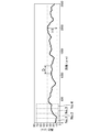
なお、1視野当たり1つの任意の断面について、微細凹凸模様3の表面形状プロファイルを得、3視野の結果の平均値を測定結果として得た。実施例2及び比較例3の微細凹凸模様3の表面形状プロファイルの一例をそれぞれ図13及び図15に示す。
-最大高低差、ピッチについて-
例えば図13に示すように、微細凹凸模様3の表面形状プロファイルから、所定距離2500μmにおいて、第1凸部32の高さH1としての最大高低差(μm)、隣り合う凸部32,33間のピッチDの範囲(μm)を算出した。
例えば図13に示すように、微細凹凸模様3の表面形状プロファイルから、所定距離2500μmにおいて、第1凸部32の高さH1としての最大高低差(μm)、隣り合う凸部32,33間のピッチDの範囲(μm)を算出した。
-微小領域の割合について-
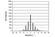
また、微細凹凸模様3の表面形状プロファイルから、所定距離2500μm当たりの微細凹凸模様3を所定長さd=0.7μmで分割して得られた微小領域sの傾斜角度θを得た。そして、得られた傾斜角度θの値に対して、所定距離2500μm当たりの微小領域sの数をプロットしたヒストグラムを得た。実施例2及び比較例3のヒストグラムの一例をそれぞれ図14及び図16に示す。
また、微細凹凸模様3の表面形状プロファイルから、所定距離2500μm当たりの微細凹凸模様3を所定長さd=0.7μmで分割して得られた微小領域sの傾斜角度θを得た。そして、得られた傾斜角度θの値に対して、所定距離2500μm当たりの微小領域sの数をプロットしたヒストグラムを得た。実施例2及び比較例3のヒストグラムの一例をそれぞれ図14及び図16に示す。
そうして、表1に示すように、所定距離2500μm当たりの微小領域sの数(全微小領域の数)に対し、傾斜角度θが-10°以上10°以下、及び-1°以上1°以下の微小領域sの数の割合を算出した。
-平坦部について-
まず、微細凹凸模様3に対して入射角45°で入射した入射光の反射光について、以下の式(1)を用いて、各微小領域sにおける反射強度IRを算出した。
まず、微細凹凸模様3に対して入射角45°で入射した入射光の反射光について、以下の式(1)を用いて、各微小領域sにおける反射強度IRを算出した。
IR=(F(α)×n×l)/I0 ・・・(1)
但し、式(1)中、αは上述の入射角、F(α)はフレネル反射率、nは微小領域の数、lは微小領域sの長さ、すなわち例えば図4の線分ABの長さ、I0は、樹脂製基材2の反射強度である。
但し、式(1)中、αは上述の入射角、F(α)はフレネル反射率、nは微小領域の数、lは微小領域sの長さ、すなわち例えば図4の線分ABの長さ、I0は、樹脂製基材2の反射強度である。
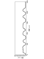
そして、図13のNo.1~No.4に例示するように、測定開始位置から距離90μm毎の領域に順に位置No.を付与し、各位置No.の領域で、各微小領域sの反射強度IRを積算した。実施例4についての反射強度IRをの積算結果の一例を図17に示す。図17に示すように、例えばNo.4、No.7等の領域で、反射強度IRの積算値が大きくなっていることが判る。このNo.4やNo.7の領域では、θ=0°近傍の平らな部分が約90μm以上の範囲に亘って形成されていると考えられる。このように、例えば図17において反射強度IRの積算値の極大となる位置No.の領域を平坦部35が形成されている領域と判定し、所定距離2500μmの間にそのような平坦部35が何個含まれるかを算出し、上述のごとく3視野の平均値を表1の平坦部の数(個/2500μm)として算出した。そして、所定距離2500μmを、算出した平坦部35の数で除して、平坦部1個当たりの距離(μm/個)を算出した。
-算術平均粗さについて-
さらに、微細凹凸模様3上の微小な凹凸形状について検討するため、カットオフ値λs=2.5μm及びλc=80μmにおける算術平均粗さRaを測定した。なお、λsは、低域フィルタで、設定値よりも短波長成分を除去するものであり、またλcとは、高域フィルタで、設定値よりも高波長のうねり成分を除去するものである。
さらに、微細凹凸模様3上の微小な凹凸形状について検討するため、カットオフ値λs=2.5μm及びλc=80μmにおける算術平均粗さRaを測定した。なお、λsは、低域フィルタで、設定値よりも短波長成分を除去するものであり、またλcとは、高域フィルタで、設定値よりも高波長のうねり成分を除去するものである。
<光学特性測定試験>
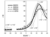
変角分光光度計(株式会社村上色彩技術研究所製、3次元変角分光システムGCMS-4)を用いてL*値を測定した。なお、入射角αは45°、反射光の検出器の受光角度である受光角γは-80°~80°(5°きざみ)であった。測定結果を図18、表1に示す。
変角分光光度計(株式会社村上色彩技術研究所製、3次元変角分光システムGCMS-4)を用いてL*値を測定した。なお、入射角αは45°、反射光の検出器の受光角度である受光角γは-80°~80°(5°きざみ)であった。測定結果を図18、表1に示す。
なお、受光角γ=45°の明度L*値、L*
45°は、反射光のハイライト部分に寄与する正反射の量を示している。受光角γ=45°と受光角γ=20°の明度L*値の差L*
45°-L*
20°及び受光角γ=55°と受光角γ=75°の明度L*値の差L*
55°-L*
75°は、いずれも正反射近傍の反射光の量を示す。受光角-80°≦γ≦-55°の反射光の明度L*値の平均値L*
-80°~L*
-55°は、反射光のうち、シェード部分の黒さに寄与する。
比較例2の試験片に比較して、実施例1~3の試験片では、ハイライト部分のL*値が増加し、シェード部分のL*値が低下していることが判る。
なお、樹脂製基材のL*
-80°は、図11に示す樹脂製試験片11であって、表面12に微細凹凸模様3が形成されていない試験片について、光学特性測定試験を行い、得られた結果である。
<目視観察試験>
試験者3人(男性2人、女性1人、30歳~50歳、矯正視力両目0.5以上)が、樹脂製試験片の表面から目を30cm離した状態で、当該表面の観察を行った。評価項目は、マクロ質感としての(1)艶、(2)シェードの黒さ、及びミクロ質感としての(3)粒子感の3項目とした。評価項目(1)~(3)のそれぞれについて、各試験者は、「5…非常によい、4…よい、3…普通、2…悪い、1…非常に悪い」の5段階評価を行った。そして、全試験者の評価結果の平均値から、A…4超5以下、B…3超4以下、C…2超3以下、D…2以下として、観察結果を得た。
試験者3人(男性2人、女性1人、30歳~50歳、矯正視力両目0.5以上)が、樹脂製試験片の表面から目を30cm離した状態で、当該表面の観察を行った。評価項目は、マクロ質感としての(1)艶、(2)シェードの黒さ、及びミクロ質感としての(3)粒子感の3項目とした。評価項目(1)~(3)のそれぞれについて、各試験者は、「5…非常によい、4…よい、3…普通、2…悪い、1…非常に悪い」の5段階評価を行った。そして、全試験者の評価結果の平均値から、A…4超5以下、B…3超4以下、C…2超3以下、D…2以下として、観察結果を得た。
表1に示すように、比較例1~3の樹脂製試験片では、いずれの試験片においても、2項目以上でDの評価結果が得られた。一方、実施例1~4の樹脂製試験片では、実施例1の樹脂製試験片において粒子感がやや不十分であるものの、総じてマクロ質感及びミクロ質感の双方において優れていることが判った。
本開示は、表面に十分な光沢及び陰影を有し、外観の意匠性に優れた樹脂製部材、樹脂製部材の成形用金型及び樹脂製部材の製造方法をもたらすことができるので、極めて有用である。
1 樹脂製部材
2 樹脂製基材
3 微細凹凸模様
31 凹部
32 第1凸部
33 第2凸部
31a 最底点
36 微小な凹凸形状
5 成形用金型
6 金型基材
7 シボ模様
76 微小なシボ形状
C 自動車
D ピッチ
H1 (第1凸部の)高さ
H2 (第2凸部の)高さ
K 断面
P 基準面
S1 金型準備工程
S2 第1エッチング工程
S3 第2エッチング工程
S4 ブラスト工程
S41 研磨工程
S5 成形工程
s 微小領域
θ 傾斜角度
α 入射角
β 反射角
γ 受光角
2 樹脂製基材
3 微細凹凸模様
31 凹部
32 第1凸部
33 第2凸部
31a 最底点
36 微小な凹凸形状
5 成形用金型
6 金型基材
7 シボ模様
76 微小なシボ形状
C 自動車
D ピッチ
H1 (第1凸部の)高さ
H2 (第2凸部の)高さ
K 断面
P 基準面
S1 金型準備工程
S2 第1エッチング工程
S3 第2エッチング工程
S4 ブラスト工程
S41 研磨工程
S5 成形工程
s 微小領域
θ 傾斜角度
α 入射角
β 反射角
γ 受光角
Claims (7)
- 樹脂製基材と、
前記樹脂製基材の表面に形成され、複数の凹部及び複数の凸部からなる微細凹凸模様とを備えた樹脂製部材であって、
単位面積当たりの前記微細凹凸模様に含まれる最も深い任意の3つの最底点を通る平面を基準面とし、該微細凹凸模様上の任意の点における該基準面からの最短距離を該微細凹凸模様の高さとしたときに、
前記複数の凸部は、
高さが15μm以上35μm以下の複数の第1凸部と、
高さが前記第1凸部の高さの1/4以上3/4以下である複数の第2凸部とを備えており、
前記複数の凸部のうち、互いに隣り合う2つの前記凸部の頂点間距離は、100μm以上500μm以下であり、
前記基準面に垂直な断面において、所定距離当たりの前記微細凹凸模様を所定長さの微小領域に分割したときに、該微小領域の前記基準面に対する傾斜角度が-10°以上10°以下である該微小領域の数は、所定距離当たりの前記微細凹凸模様に含まれる全微小領域の数の78%以上95%以下であり、
前記傾斜角度が-1°以上1°以下である前記微小領域の数は、前記全微小領域の数の25%以上40%以下である
ことを特徴とする樹脂製部材。 - 請求項1において、
前記基準面に垂直な断面において、前記微細凹凸模様は、前記基準面と平行な方向に90μm以上の長さを有する平坦部を、長さ300μm以上500μm以下の範囲内に1個の割合で有する
ことを特徴とする樹脂製部材。 - 請求項1又は請求項2において、
設定値よりも短波長成分を除去する低域フィルタの該設定値をカットオフ値λsとし、
設定値よりも高波長成分を除去する高域フィルタの該設定値をカットオフ値λcとしたときに、
前記微細凹凸模様が形成された表面の、前記カットオフ値λs=2.5μm及び前記カットオフ値λc=80μmにおける算術平均粗さRaは、0.2μm以上0.4μm以下である
ことを特徴とする樹脂製部材。 - 請求項1乃至請求項3のいずれか一において、
入射角45°で変角分光光度計を用いて測定された受光角γの明度をL*値としたときに、
受光角γ=45°の明度L* 45°は85以上130以下であり、
前記明度L* 45°と、受光角γ=20°の明度L* 20°との差であるL* 45°-L* 20°は48以上104以下である
ことを特徴とする樹脂製部材。 - 請求項1乃至請求項4のいずれか一において、
入射角45°で変角分光光度計を用いて測定された受光角γの明度をL*値としたときに、
前記微細凹凸模様が形成されていない前記樹脂製基材における、受光角γ=-80°の明度L* -80°は6未満である
ことを特徴とする樹脂製部材。 - 請求項1乃至請求項5のいずれか一に記載の樹脂製部材を製造するための成形用金型。
- 請求項6の成形用金型を用いて射出成形により前記樹脂製部材を製造する
ことを特徴とする樹脂製部材の製造方法。
Priority Applications (3)
| Application Number | Priority Date | Filing Date | Title |
|---|---|---|---|
| US17/295,980 US11850780B2 (en) | 2018-11-22 | 2019-11-15 | Resin member, mold for molding resin member, and method for manufacturing resin member |
| CN201980076322.5A CN113056358B (zh) | 2018-11-22 | 2019-11-15 | 树脂部件、树脂部件的成型用模具及树脂部件的制造方法 |
| EP19886763.2A EP3885099B1 (en) | 2018-11-22 | 2019-11-15 | Resin member, mold for molding resin member, and method for manufacturing resin member |
Applications Claiming Priority (2)
| Application Number | Priority Date | Filing Date | Title |
|---|---|---|---|
| JP2018-219766 | 2018-11-22 | ||
| JP2018219766A JP7103186B2 (ja) | 2018-11-22 | 2018-11-22 | 樹脂製部材、樹脂製部材の成形用金型及び樹脂製部材の製造方法 |
Publications (1)
| Publication Number | Publication Date |
|---|---|
| WO2020105563A1 true WO2020105563A1 (ja) | 2020-05-28 |
Family
ID=70773589
Family Applications (1)
| Application Number | Title | Priority Date | Filing Date |
|---|---|---|---|
| PCT/JP2019/044955 Ceased WO2020105563A1 (ja) | 2018-11-22 | 2019-11-15 | 樹脂製部材、樹脂製部材の成形用金型及び樹脂製部材の製造方法 |
Country Status (5)
| Country | Link |
|---|---|
| US (1) | US11850780B2 (ja) |
| EP (1) | EP3885099B1 (ja) |
| JP (1) | JP7103186B2 (ja) |
| CN (1) | CN113056358B (ja) |
| WO (1) | WO2020105563A1 (ja) |
Families Citing this family (5)
| Publication number | Priority date | Publication date | Assignee | Title |
|---|---|---|---|---|
| JP7141982B2 (ja) * | 2019-06-26 | 2022-09-26 | 株式会社ニフコ | 車両用内装材及び車両用内装材の製造方法 |
| JP7638694B2 (ja) * | 2020-12-16 | 2025-03-04 | キヤノン株式会社 | 成形品、電子機器、および成形品の製造方法 |
| CN114800965A (zh) * | 2022-04-13 | 2022-07-29 | 河南工业职业技术学院 | 一种自动计算空间多边形同侧邻接区域面的方法、装置 |
| WO2024162832A1 (ko) * | 2023-01-31 | 2024-08-08 | 삼성전자 주식회사 | 저굴절 코팅층을 포함하는 전자 장치 |
| US20250303483A1 (en) * | 2024-03-28 | 2025-10-02 | Ford Global Technologies, Llc | Injection molding tool and a method of forming an injection molding tool |
Citations (6)
| Publication number | Priority date | Publication date | Assignee | Title |
|---|---|---|---|---|
| JPH09262837A (ja) * | 1996-03-29 | 1997-10-07 | Asahi Chem Ind Co Ltd | 艶消し状金型の製法及び該金型を用いた成形法 |
| JP2006068972A (ja) * | 2004-08-31 | 2006-03-16 | World Etching:Kk | 樹脂成形用金型及びその低グロス化方法並びに樹脂成形品 |
| JP2013139091A (ja) | 2011-12-28 | 2013-07-18 | Toyota Motor Corp | 樹脂成形品、樹脂成形用金型、及び、樹脂成形方法 |
| JP2014043047A (ja) * | 2012-08-27 | 2014-03-13 | Mazda Motor Corp | シボ付き樹脂成形品 |
| JP2015136819A (ja) * | 2014-01-21 | 2015-07-30 | マツダ株式会社 | 樹脂成形用金型及びその製造方法 |
| JP2016107708A (ja) * | 2014-12-03 | 2016-06-20 | 南条装備工業株式会社 | 車両の内装用樹脂成形品 |
Family Cites Families (8)
| Publication number | Priority date | Publication date | Assignee | Title |
|---|---|---|---|---|
| TW200504384A (en) * | 2003-07-24 | 2005-02-01 | Zeon Corp | Molded article for anti-reflection and method for preparing the article |
| JP5348591B2 (ja) * | 2009-09-03 | 2013-11-20 | 住友化学株式会社 | 防眩フィルムの製造方法および防眩フィルム作製のための金型の製造方法 |
| JP2012108502A (ja) * | 2010-10-28 | 2012-06-07 | Mitsubishi Rayon Co Ltd | 微細凹凸構造を表面に有する物品の製造方法 |
| DK2823357T3 (en) * | 2012-03-09 | 2016-06-13 | Univ Danmarks Tekniske | PROCEDURE FOR MANUFACTURING A TOOL PART FOR A INJECTION CASTING PROCESS, A HOT PRINTING PROCESS, A NANO PRINTING PROCESS, OR AN EXTRUDING PROCESS |
| JP2014066975A (ja) * | 2012-09-27 | 2014-04-17 | Asahi Kasei E-Materials Corp | 微細凹凸成形体及び微細凹凸成形鋳型並びにそれらの製造方法 |
| WO2014065136A1 (ja) * | 2012-10-22 | 2014-05-01 | 三菱レイヨン株式会社 | 積層構造体およびその製造方法と、物品 |
| JP5660235B2 (ja) * | 2013-03-18 | 2015-01-28 | 王子ホールディングス株式会社 | 表面微細凹凸体および表面微細凹凸体の製造方法 |
| WO2016199054A2 (en) * | 2015-06-10 | 2016-12-15 | Sabic Global Technologies B.V. | Plastic surfaces having surface structures and methods of making the same |
-
2018
- 2018-11-22 JP JP2018219766A patent/JP7103186B2/ja active Active
-
2019
- 2019-11-15 CN CN201980076322.5A patent/CN113056358B/zh active Active
- 2019-11-15 WO PCT/JP2019/044955 patent/WO2020105563A1/ja not_active Ceased
- 2019-11-15 US US17/295,980 patent/US11850780B2/en active Active
- 2019-11-15 EP EP19886763.2A patent/EP3885099B1/en active Active
Patent Citations (6)
| Publication number | Priority date | Publication date | Assignee | Title |
|---|---|---|---|---|
| JPH09262837A (ja) * | 1996-03-29 | 1997-10-07 | Asahi Chem Ind Co Ltd | 艶消し状金型の製法及び該金型を用いた成形法 |
| JP2006068972A (ja) * | 2004-08-31 | 2006-03-16 | World Etching:Kk | 樹脂成形用金型及びその低グロス化方法並びに樹脂成形品 |
| JP2013139091A (ja) | 2011-12-28 | 2013-07-18 | Toyota Motor Corp | 樹脂成形品、樹脂成形用金型、及び、樹脂成形方法 |
| JP2014043047A (ja) * | 2012-08-27 | 2014-03-13 | Mazda Motor Corp | シボ付き樹脂成形品 |
| JP2015136819A (ja) * | 2014-01-21 | 2015-07-30 | マツダ株式会社 | 樹脂成形用金型及びその製造方法 |
| JP2016107708A (ja) * | 2014-12-03 | 2016-06-20 | 南条装備工業株式会社 | 車両の内装用樹脂成形品 |
Non-Patent Citations (1)
| Title |
|---|
| See also references of EP3885099A4 |
Also Published As
| Publication number | Publication date |
|---|---|
| CN113056358A (zh) | 2021-06-29 |
| EP3885099A1 (en) | 2021-09-29 |
| EP3885099A4 (en) | 2021-12-29 |
| JP7103186B2 (ja) | 2022-07-20 |
| US20220024095A1 (en) | 2022-01-27 |
| CN113056358B (zh) | 2022-09-16 |
| US11850780B2 (en) | 2023-12-26 |
| EP3885099B1 (en) | 2023-08-09 |
| JP2020082498A (ja) | 2020-06-04 |
Similar Documents
| Publication | Publication Date | Title |
|---|---|---|
| WO2020105563A1 (ja) | 樹脂製部材、樹脂製部材の成形用金型及び樹脂製部材の製造方法 | |
| CN101506692B (zh) | 光学层积体、偏振片和图像显示装置 | |
| US7697205B2 (en) | Anti-reflection fine structure, anti-reflection mold body, method of producing the anti-reflection mold body, and automobile part | |
| CN103299217B (zh) | 防反射膜、防反射膜的制造方法、偏振片和图像显示装置 | |
| JP2007187952A (ja) | 防眩フィルム、その製造方法、そのための金型の製造方法、及び表示装置 | |
| CN101268389A (zh) | 防静电防眩薄膜 | |
| CN101163994A (zh) | 防眩性光学层叠体 | |
| TW200907398A (en) | Anti-dazzling film, anti-dazzling polarizing plate, and image display device | |
| JP2009204687A (ja) | 防眩フィルム、防眩性偏光板および画像表示装置 | |
| KR20090023178A (ko) | 반사 방지 구조 및 반사 방지 성형체와, 반사 방지 성형체를 이용한 자동차 부품 | |
| WO2018061217A1 (ja) | 積層塗膜及び塗装物 | |
| CN109789438B (zh) | 叠层涂膜及涂装物 | |
| JP4844254B2 (ja) | 防眩フィルム及び画像表示装置 | |
| CN107735185A (zh) | 叠层涂膜及涂装物 | |
| US9457501B2 (en) | Resin molding, method for manufacturing the same, and metal mold for manufacturing the same | |
| WO2018061216A1 (ja) | 積層塗膜及び塗装物 | |
| JP2009020355A (ja) | 反射防止構造及び構造体 | |
| JP6641720B2 (ja) | 低反射シート | |
| JP6631282B2 (ja) | 車両用内装材および車両用内装材用フィルム | |
| CN116472124B (zh) | 叠层涂膜及涂装物 | |
| EP4223517A1 (en) | Multilayered coating film and coated article | |
| EP4227086A1 (en) | Multilayered coating film and coated article | |
| JP6696114B2 (ja) | 低反射シート | |
| JP2025015295A (ja) | 樹脂製部材、樹脂製部材の成形用金型及び樹脂製部材の製造方法 | |
| ES2950097T3 (es) | Método para producir una piel elastomérica |
Legal Events
| Date | Code | Title | Description |
|---|---|---|---|
| 121 | Ep: the epo has been informed by wipo that ep was designated in this application |
Ref document number: 19886763 Country of ref document: EP Kind code of ref document: A1 |
|
| NENP | Non-entry into the national phase |
Ref country code: DE |
|
| ENP | Entry into the national phase |
Ref document number: 2019886763 Country of ref document: EP Effective date: 20210622 |