WO2020105690A1 - 雄コネクタ - Google Patents
雄コネクタInfo
- Publication number
- WO2020105690A1 WO2020105690A1 PCT/JP2019/045517 JP2019045517W WO2020105690A1 WO 2020105690 A1 WO2020105690 A1 WO 2020105690A1 JP 2019045517 W JP2019045517 W JP 2019045517W WO 2020105690 A1 WO2020105690 A1 WO 2020105690A1
- Authority
- WO
- WIPO (PCT)
- Prior art keywords
- valve body
- male connector
- tip
- needle
- side hole
- Prior art date
- Legal status (The legal status is an assumption and is not a legal conclusion. Google has not performed a legal analysis and makes no representation as to the accuracy of the status listed.)
- Ceased
Links
Images










Classifications
-
- A—HUMAN NECESSITIES
- A61—MEDICAL OR VETERINARY SCIENCE; HYGIENE
- A61M—DEVICES FOR INTRODUCING MEDIA INTO, OR ONTO, THE BODY; DEVICES FOR TRANSDUCING BODY MEDIA OR FOR TAKING MEDIA FROM THE BODY; DEVICES FOR PRODUCING OR ENDING SLEEP OR STUPOR
- A61M39/00—Tubes, tube connectors, tube couplings, valves, access sites or the like, specially adapted for medical use
- A61M39/10—Tube connectors; Tube couplings
-
- A—HUMAN NECESSITIES
- A61—MEDICAL OR VETERINARY SCIENCE; HYGIENE
- A61M—DEVICES FOR INTRODUCING MEDIA INTO, OR ONTO, THE BODY; DEVICES FOR TRANSDUCING BODY MEDIA OR FOR TAKING MEDIA FROM THE BODY; DEVICES FOR PRODUCING OR ENDING SLEEP OR STUPOR
- A61M39/00—Tubes, tube connectors, tube couplings, valves, access sites or the like, specially adapted for medical use
- A61M39/22—Valves or arrangement of valves
- A61M39/26—Valves closing automatically on disconnecting the line and opening on reconnection thereof
- A61M2039/267—Valves closing automatically on disconnecting the line and opening on reconnection thereof having a sealing sleeve around a tubular or solid stem portion of the connector
- A61M2039/268—Valves closing automatically on disconnecting the line and opening on reconnection thereof having a sealing sleeve around a tubular or solid stem portion of the connector wherein the stem portion is moved for opening and closing the valve, e.g. by translation, rotation
Definitions
- the present invention relates to a male connector connected to a female connector in a fluid channel used in the medical field.
- fluid passages such as infusion lines and blood transfusion lines have been used to administer or collect liquids such as water, electrolytes, anticancer drugs, and other nutrients, nutrients, blood, and contrast media.
- liquids such as water, electrolytes, anticancer drugs, and other nutrients, nutrients, blood, and contrast media.
- a male connector is provided at the end of one flow channel and a female connector is provided at the end of the other flow channel.
- the connector and the female connector are adapted to be connected to each other.
- a male connector having a hollow needle or a male luer is provided at the end of a flow path extending from a container such as a syringe in which a drug solution such as an anticancer drug is sealed, a catheter or the like inserted into a patient is used.
- a catheter or the like inserted into a patient is used.
- the opening of the flow path be closed in order to prevent external exposure or leakage of the chemical liquid or the like when the male connector is not connected.
- a male connector is disclosed in, for example, Japanese Patent Laid-Open No. 2013-121525 (Patent Document 1). That is, in the embodiment described in FIGS. 1 to 9 of Patent Document 1, the hollow valve member (16) is positioned on the inner peripheral side of the male luer in the male connector (10), for example, in FIG. As shown in FIG. 5, when the female connector (92) is not connected, the tip of the valve member (16) having the window (54) opening to the peripheral wall is fitted into the tip opening of the male luer (22). This shuts off the fluid flow path.
- Patent Document 2 also discloses a male connector in which an opening of a flow path is closed when not connected to a female connector. That is, in the embodiments described in FIGS. 1 to 5 of Patent Document 2, the convex portion (22) of the housing body (20a) and the concave portion (31) of the moving body (30a) when not connected to the female connector (2a). Engage with each other to prevent the moving body (30a) from moving in the axial direction with respect to the housing body (20a), and the opening (42) of the flow path (first flow path 41) of the male connector (1a) is It is closed by the valve body (50a).
- the female connector (2a) is connected to the moving body (30a) of the male connector (1a) to move the female connector (2a) and the moving body (30a) to the proximal end side with respect to the housing body (20a).
- the engagement between the convex portion (22) and the concave portion (31) is released.
- the flow channel pipe member (40a) that configures the flow channel (first flow channel 41) of the male connector (1a).
- the male connector (1a) is inserted into the female connector (2a) by penetrating the valve body (50a) and the elastic valve body (70) into the female connector (1a).
- the flow path (second flow path 66) of the connector (2a) is communicated with each other.
- the operability may be deteriorated, or the elastically deformable portion of the housing body (20a) may be grasped by a hand so that the concave portion (31) may be removed.
- the convex portion (22) may not be easily detached, and that the stability and reliability of operation may not be sufficiently secured.
- the release of the engagement between the convex portion (22) and the concave portion (31) and the movement of the female connector (2a) and the moving body (30a) to the proximal end side are performed as a series of operations. Therefore, for example, when the engaging force between the convex portion (22) and the concave portion (31) is set to be large, the operating force necessary for releasing the engagement also becomes large, and the connection between the male connector (1a) and the female connector (2a) is increased. There was a risk that it would interfere with operation.
- the engaging force between the convex portion (22) and the concave portion (31) is set to be small, the engagement between the convex portion (22) and the concave portion (31) is unintentionally released, and the moving body (30a) is proximal.
- the flow path (first flow path 41) of the male connector (1a) may be opened when it moves to the end side and is not connected to the female connector (2a). That is, the engagement between the convex portion (22) and the concave portion (31) is released, and the female connector (2a) and the moving body (30a) are moved toward the proximal end side as a series of operations. It has been difficult to achieve both improved stability and improved transfer operability.
- the problem to be solved by the present invention is to stably close the flow path when the female connector is not connected, to improve the stability and reliability of connection operation to the female connector, and to It is possible to achieve both stable closing of the flow path at the time of connection and improvement of operability of connection operation to the female connector, and improvement of blocking performance of the flow path from the external space at the time of connection with the female connector, It is an object of the present invention to provide a male connector having a novel structure capable of solving at least one of the problems inherent in the male connector having the conventional structure, such as more reliably preventing the exposure of the chemical liquid.
- a first aspect is provided with a side hole needle whose inner hole is opened laterally at a tip portion of a hollow needle, and the side hole needle is inserted into a female connector which is a counterpart of connection, whereby a fluid flow path is formed.
- An elastic cover valve body that covers a side opening of the inner hole at a tip portion of the side hole needle is provided movably in the axial direction with respect to the side hole needle.
- a hard restraining member that covers the outer periphery of the cover valve body is provided.
- the opening of the side hole needle is covered with the elastic cover valve body and closed, the closing of the male connector when not connected to the female connector can be stably realized. Furthermore, the hard restraining member that covers the outer periphery of the cover valve body can stabilize the deformation mode of the cover valve body, and can also improve the closing performance of the side hole needle by the cover valve body.
- a second aspect is the male connector according to the first aspect, wherein the restraint member includes a proximal end side protruding portion that extends toward the proximal end side of the side hole needle, and the proximal end side protrusion
- a guide portion is provided in the portion for guiding the axial movement of the restraining member with respect to the male connector housing.
- the restraining member can be moved more smoothly in the axial direction, and the deformation aspect of the cover valve body can be stabilized.
- a third aspect is the male connector according to the first or second aspect, which includes a male connector housing having a cylindrical peripheral wall portion that covers the outer periphery of the restraint member.
- the male connector of this aspect it is possible to provide, for example, a positioning means for positioning the cover valve body inside the cylindrical peripheral wall portion, and it is possible to prevent the positioning of the cover valve body from being unintentionally released.
- a fourth aspect is the male connector according to the third aspect, wherein the cylindrical peripheral wall portion is formed separately from the needle hub of the side hole needle.
- a structure in which the outer peripheral side of the restraint member is covered with the tubular peripheral wall portion can be easily realized by assembling the needle hub with the restraint member arranged inside the tubular peripheral wall portion. ..
- a fifth aspect is the male connector according to the third or fourth aspect, wherein the cylindrical peripheral wall portion has a cylindrical cover portion having a diameter larger than that of the cylindrical peripheral wall portion and protruding toward the tip side. Is provided.
- the cover portion since the cover portion has a sufficiently large diameter, contact with the female connector is prevented even when the female connector is brought close to the connector, and good operability is exhibited. To be done. Further, since the cover portion has a sufficient length and protrudes toward the distal end side, the outer peripheral side of the cover valve body can be more surely covered with the cover portion, and the user may unintentionally contact the cover valve body. Leakage or exposure of the drug solution may be prevented.
- a sixth aspect is the male connector according to any one of the first to fifth aspects, wherein the cover valve body is removably attached to the female connector and the cover valve body is superposed on a valve member of the female connector.
- a connecting portion is provided to be connected in abutting state, and the side hole needle causes the side hole needle to contact the cover valve body and the female member while the cover valve body is in contact with the valve member of the female connector by the connecting portion. The connector can be inserted into and removed from the valve member.
- the side hole needle is inserted into and removed from the valve member of the cover valve body and the valve member of the female connector in a state of being overlapped with each other, thereby further preventing exposure and leakage of the chemical liquid and the like. Can be done.
- a seventh aspect is provided with a tubular body having an inner hole opened at the tip portion, and the fluid passage can be communicated by inserting the tip portion of the tubular body into a female connector as a connection partner.
- a male connector which is provided with an elastic cover valve body that covers an opening of the distal end portion of the tubular body, and restricts axial movement of the tubular body in a holding member that holds the cover valve body. Then, a releasable movement limiting mechanism for holding the opening of the distal end portion of the tubular body in a sealed state by the cover valve body is provided.
- the movement of the holding member that holds the cover valve body is restricted, so that the stability of the sealed state of the opening of the distal end portion of the tubular body by the cover valve body can be improved.
- An eighth aspect is provided with a tubular body having an inner hole that opens at the tip portion and an elastic cover valve body that covers the opening of the tip portion of the tubular body.
- a male connector that projects from the cover valve body and inserts it into a female connector that is a connection partner to connect the fluid flow paths
- the front end surface of the cover valve body has an axial end from the outer periphery toward the center.
- the central portion of the tip end surface of the cover valve body is a curved tip end surface that is convex toward the tip, while it is formed in a centrally projecting shape that protrudes to the side, and from the central portion toward the outer circumference.
- the region that spreads out is a reverse curved inclined surface that is concave toward the tip.
- the region extending from the central portion toward the outer periphery of the tip end surface of the cover valve body is the reverse curved inclined surface, so that the female connector can be connected to the female connector. It is possible to reduce the gap formed between the overlapping surface with the surface of the valve body on the side, for example, to make a close contact state. As a result, for example, it is possible to prevent the chemical liquid or the like from seeping out or leaking into the gap.
- the exposure prevention performance of the cover valve body may be deteriorated due to the heat effect during sterilization (especially, the heat is exerted in the initial state where the needle tip is pierced), or the needle may penetrate after being used multiple times. Repeatedly making the slit easier to open or the valve body being pulled by the needle due to frictional resistance etc. resulting in a deformed state, the exposure prevention performance of the cover valve body may decrease. all right.
- the exposure prevention performance on the base end side of the cover valve body is a new point of interest (one of new challenges).
- a slit having a single letter or a radial shape is adopted in the cover valve body as a valve body. Therefore, when inserting a tubular body such as a side hole needle, a gap is likely to occur on both sides in the slit direction.
- a ninth aspect is provided with a side hole needle having an inner hole opened laterally at the tip portion of the hollow needle, and by inserting the side hole needle into a female connector that is a connection partner, a fluid flow path is formed.
- An elastic cover valve body that covers a side opening of the inner hole at a tip portion of the side hole needle is provided movably in the axial direction with respect to the side hole needle.
- at least the portion of the cover valve body on the base end side on the central axis into which the side hole needle is inserted is a pin hole having a smaller diameter than the side hole needle.
- a pinhole having a diameter smaller than that of the sidehole needle is provided in place of the slit, so that when the sidehole needle is inserted into and removed from the cover valve body, Compared with the case, the gap between the cover valve body and the side hole needle can be made smaller, so that leakage or exposure of the chemical liquid can be prevented more reliably.
- a tenth aspect is provided with a side hole needle having an inner hole opened laterally at a tip portion of a hollow needle, and by inserting the side hole needle into a female connector as a connection partner, a fluid flow path is formed.
- An elastic cover valve body that covers a side opening of the inner hole at a tip portion of the side hole needle is provided movably in the axial direction with respect to the side hole needle.
- a biasing means for biasing the cover valve body from the base end side is provided toward the tip end side that covers the side opening of the inner hole of the side hole needle.
- a limiting member is provided which is superposed on the base end face to limit the deformation of the base end face.
- the male connector of this aspect even if the cover valve body is biased from the base end side, the deformation of the base end face of the cover valve body is limited by the limiting member. It is possible to prevent a gap from being generated between them and prevent the chemical solution from leaking or exposing to the proximal side through the gap. Further, for example, when the biasing means is fixed to the cover valve body through the restricting member, it is possible to avoid local deformation of the cover valve body by the biasing means, and the side hole needle and the cover valve are It is also possible to prevent a gap from being formed between the body and the body.
- An eleventh aspect is provided with a side hole needle whose inner hole is opened laterally at the tip portion of the hollow needle, and by inserting the side hole needle into a female connector that is a connection partner, a fluid flow path is formed.
- An elastic cover valve body that covers a side opening of the inner hole at a tip portion of the side hole needle is provided movably in the axial direction with respect to the side hole needle.
- an annular seal portion that seals between the cover valve body and the outer peripheral surface of the side hole needle is provided on the base end side of the cover valve body.
- the annular seal portion can prevent the chemical liquid from further leaking and exposing.
- a twelfth aspect is provided with a side hole needle whose inner hole is opened laterally at the tip portion of the hollow needle, and by inserting the side hole needle into a female connector which is a connection partner, a fluid flow path is formed.
- An elastic cover valve body that covers a side opening of the inner hole at a tip portion of the side hole needle is provided movably in the axial direction with respect to the side hole needle.
- a plurality of lateral openings of the side hole needle are provided on the same circumference with a flow passage cross-sectional area of 70% or less of the inner hole of the side hole needle.
- the cross-sectional area of the lateral opening of the side hole needle is made smaller than a predetermined size, whereby the risk of leakage of the chemical liquid from the opening can be reduced. Further, by providing a plurality of such openings on the circumference, a sufficient amount of fluid flowing through the side hole needle can be secured.
- a thirteenth aspect is provided with a side hole needle whose inner hole is opened laterally at the tip portion of the hollow needle, and by inserting the side hole needle into a female connector that is a connection partner, a fluid flow path is formed.
- An elastic cover valve body that covers a side opening of the inner hole at a tip portion of the side hole needle is provided movably in the axial direction with respect to the side hole needle.
- the inner and outer diameters of the tip portion of the side hole needle that is inserted into the cover valve body are smaller than the inner and outer diameters of the base end portions of the side hole needles.
- the male connector of this aspect by forming the portion of the side hole needle that is inserted into the valve member of the cover valve body or the female connector to have a small diameter, the fluid flow efficiency in the small diameter portion is reduced and the leakage of the chemical liquid occurs. And the risk of exposure can be reduced, and a large amount of fluid flowing through the side hole needle can be secured by forming the base end portion that cannot be inserted into the cover valve body or valve member with a large diameter. ..
- a fourteenth aspect is provided with a side hole needle whose inner hole is opened laterally at the tip portion of the hollow needle, and by inserting the side hole needle into a female connector that is a connection partner, the fluid flow path is formed.
- An elastic cover valve body that covers a side opening of the inner hole at a tip portion of the side hole needle is provided movably in the axial direction with respect to the side hole needle.
- the cover valve body is more flexible than the valve member of the female connector.
- the cover valve body formed more flexibly than the valve member follows the deformation of the valve member. Since it is possible to deform and reduce the possibility of a gap being formed between the cover valve body and the valve member, leakage and exposure of the chemical liquid can be more effectively prevented.
- the flow channel can be stably closed when the female connector is not connected, the stability, reliability, and operability of the connection operation can be improved, and the flow channel when connecting with the female connector can be improved. It is possible to provide a male connector capable of solving at least one of the problems inherent in a male connector having a conventional structure, such as improving the shut-off performance to the external space of the above and more reliably preventing the leakage of a chemical solution.
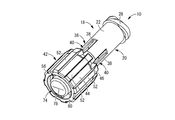
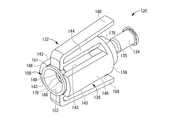
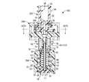
- FIG. 1 The perspective view which shows the initial state in the male connector as the 1st Embodiment of this invention.
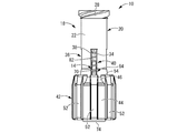
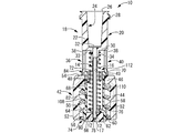
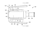
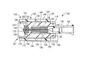
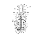
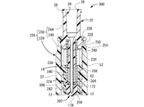
- the front view in the male connector shown by FIG. FIG. 2 is a vertical sectional view of the male connector shown in FIG. 1.
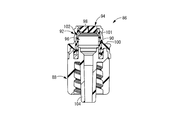
- FIG. 3 is a vertical sectional view showing a specific example of a female connector that can be connected to the male connector shown in FIG. 1.
- FIG. 6 is a vertical sectional view showing a connection state between the male connector shown in FIG. 1 and the female connector shown in FIG. 5.
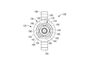
- the front view in the male connector shown by FIG. FIG. 8 is a left side view of the male connector shown in FIG. 7.
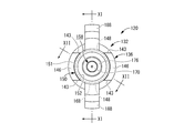
- FIG. 8 is a right side view of the male connector shown in FIG. 7.
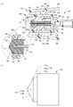
- 9A is a cross-sectional view taken along line XI-XI in FIG. 9, and
- FIG. 9B is a side view showing a single cover valve body.
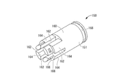
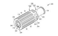
- FIG. 8 is a perspective view showing a restraint member that constitutes the male connector shown in FIG. 7.
- FIG. 8 is a vertical cross-sectional view showing a specific example of a female connector that can be connected to the male connector shown in FIG. 7.
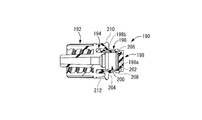
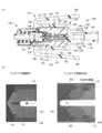
- 7A is a vertical cross-sectional view showing a connection state between the male connector shown in FIG. 7 and the female connector shown in FIG. 15, and FIG. Fluoroscopic image.
- FIG. 18 is a vertical sectional view of the male connector shown in FIG. 17.
- FIG. 18 is an exploded perspective view of the male connector shown in FIG. 17.
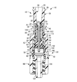
- the longitudinal cross-sectional view which shows the initial state in the male connector as the 4th Embodiment of this invention.
- FIG. 21 is a vertical cross-sectional view showing a state in which a female connector is connected to the male connector shown in FIG. 20.
- FIG. 22 is a vertical cross-sectional view showing a state in which the side hole needle of the male connector shown in FIG. 21 is inserted into the female connector.
- FIG. 24 is a sectional view taken along line XXIV-XXIV in FIG. 23.
- FIG. 26 is a sectional view taken along line XXVI-XXVI in FIG. 25.
- FIG. 25 It is a longitudinal cross-sectional view which shows another aspect of the male connector which concerns on this invention, Comprising: It is a figure corresponding to FIG.
- FIG. 1 It is a longitudinal cross-sectional view which shows another aspect of the male connector which concerns on this invention, Comprising: It is a figure corresponding to FIG. It is a figure which shows a specific example of the cover valve body which can be employ
- FIGS. 1 to 4 show a male connector 10 as a first embodiment of the present invention.
- the male connector 10 is provided with a side hole needle 14 as a hollow needle having an opening 12 on the side, and the side hole needle 14 or a member into which the side hole needle 14 is inserted (details will be described later) is a male luer.
- the male connector 10 and the female connector are connected to each other so that the fluid flow path is in communication with each other by being inserted into the female luer of the female connector which is a counterpart of the connection.
- the axial direction means the vertical direction in FIG. 3, which is the central axis direction of the side hole needle 14.
- the distal side means the lower side in FIG. 3 where the opening 12 is provided in the side hole needle 14, while the proximal side means the side where the side hole needle 14 is fixed.
- the side hole needle 14 is a hollow needle formed of a metal such as stainless steel or a hard synthetic resin, and has an inner hole 16 extending in the central axis direction.
- the tip of the side hole needle 14 is closed and rounded so as to be easily inserted into the valve member 94 of the female connector 86 described later, and the tip surface 17 of the side hole needle 14 is formed by a curved surface. ..
- an opening 12 that opens in the axis-perpendicular direction (sideward) is provided at the tip portion of the side hole needle 14, and an inner hole 16 communicates with the external space through the opening 12.
- a pair of openings 12, 12 are provided on both sides in the one direction perpendicular to the axis (both sides in the left-right direction in FIG. 4).
- the male connector 10 has a male connector housing 18 for fixedly supporting the side hole needle 14.
- the male connector housing 18 is a generally cylindrical integrally-molded product made of hard synthetic resin or the like as a whole, and a female luer portion 20 having a substantially cylindrical shape is provided at the base end portion. That is, the female luer part 20 is provided with a substantially tubular luer peripheral wall part 22 extending in the axial direction, and the inner peripheral surface of the luer peripheral wall part 22 is a female luer whose inner diameter gradually expands toward the base end side. It is a lure taper surface 24.
- a male screw portion 28 protruding from the outer peripheral surface of the luer peripheral wall portion 22 to the outer peripheral side is provided in the base end side opening portion 26 of the female luer portion 20.
- the female luer portion 20 can be connected to a luer lock type syringe, connector, or the like provided at the end of the flow path extending from, for example, a bag containing a drug solution or the like.
- the connection between the female luer part 20 and the flow path extending from the bag or the like may be performed before the connection between the male connector 10 and the female connector 86, which will be described later, or after the connection.
- annular bottom wall portion 30 protruding inward is provided at the tip of the lure peripheral wall portion 22, and a through hole 32 penetrating in the axial direction is formed in the center of the bottom wall portion 30. ing. That is, the inner diameter of the luer peripheral wall portion 22 is gradually reduced toward the tip side by the female luer taper surface 24, and is further reduced at the position where the bottom wall portion 30 is formed. Have been made equal.
- the end surface on the tip end side of the bottom wall portion 30 is an annular flat surface 33 that spreads in the direction perpendicular to the axis.
- a needle hub portion 34 protruding from the inner peripheral edge portion (opening edge portion of the through hole 32) of the bottom wall portion 30 to the tip side is provided.
- the inner diameter of the needle hub 34 is equal to the inner diameter of the through hole 32, and is substantially equal to or slightly smaller than the outer diameter of the side hole needle 14.
- the base end portion of the side hole needle 14 is inserted from the tip end side opening portion of the needle hub portion 34 in a substantially press-fitted state, and is fixed by adhesion or welding as necessary, so that the base of the side hole needle 14 is The end portion is fixedly supported by the needle hub portion 34, and thus the male connector housing 18.
- the side hole needle 14 is fixedly supported by the needle hub portion 34, so that the inner hole of the female luer portion 20 passes through the through hole 32 and the inner hole of the needle hub portion 34, and It is adapted to communicate with the hole 16.
- a substantially tubular outer tubular portion 36 is provided at the axially intermediate portion of the male connector housing 18.
- the outer tubular portion 36 has a generally tubular shape as a whole, and has an outer diameter dimension substantially equal to that of the luer peripheral wall portion 22 and extends continuously from the tip end side end surface of the bottom wall portion 30 to the tip end side.
- the female luer portion 20 (luer peripheral wall portion 22) and the outer tubular portion 36 are smoothly continuous on the outer peripheral surface.
- the needle hub portion 34 and the outer tubular portion 36 are separated from each other in the direction perpendicular to the axis, and are in the inner and outer insertion states. It has a double cylinder structure.
- the outer cylindrical portion 36 is provided with a notch 38 that extends over substantially the entire length in the axial direction and penetrates in the thickness direction.
- the notch 38 has a substantially rectangular shape that is longer in the axial direction and has a larger axial dimension than the width dimension, and the base end side opening of the notch 38 is the bottom of the female luer part 20.
- the outer tubular portion 36 While being closed by the wall portion 30 and the front end side opening portion being closed by the upper bottom wall portion 46 of the lock portion 42 described later, the outer tubular portion 36 (the axially intermediate portion of the male connector housing 18) is A substantially rectangular opening window 40 that penetrates in the thickness direction is formed.
- the opening windows 40 are formed at four locations on the circumference at substantially equal intervals (about every 90 degrees) in the circumferential direction.
- the tip portion of the outer tubular portion 36 has a tapered tubular shape that slightly expands toward the tip side. Accordingly, in the initial state of the male connector 10, which will be described later, even when the engagement claw 70 is located at the tip (the tip portion of the outer cylinder portion 36) in the opening window 40, the engagement claw 70 can be more reliably formed. It is positioned in the portion 36, and the engagement between the engaging claw 70 and the upper bottom wall portion 46 is released by the contact from the outside, and the restraint member 56 is prevented from being unintentionally detached from the male connector housing 18. obtain.
- a lock portion 42 is integrally formed continuously from the tip of the outer tubular portion 36.
- the lock portion 42 has a generally tubular shape extending in the axial direction as a whole, and in the present embodiment, has a tubular shape having a larger diameter than the female luer portion 20. That is, the lock portion 42 is provided with a substantially cylindrical lock peripheral wall portion 44 extending in the axial direction, and the base end side opening portion of the lock peripheral wall portion 44 has an annular upper bottom wall portion protruding inward. 46 is provided.
- a through hole 48 penetrating in the axial direction is formed at the center of the upper bottom wall portion 46, and the inner diameter dimension of the through hole 48 is larger than the outer diameter dimension of the side hole needle 14, and the outer cylindrical portion. It is smaller than the inner diameter dimension of 36.
- the end face of the upper bottom wall portion 46 on the base end side is an annular flat face 49 extending in the direction perpendicular to the axis.
- the internal thread portion 50 is provided on the inner peripheral surface of the lock peripheral wall portion 44, while the outer peripheral surface of the lock peripheral wall portion 44 has a substantially rectangular cross section and projects to the outer peripheral side, and has a substantially total length in the axial direction.
- a ridge 52 extending across the ridge 52 is provided.
- the eight protrusions 52 are formed in the circumferential direction at substantially equal intervals (every approximately 45 degrees), so that the outer peripheral surface of the lock peripheral wall portion 44 has irregularities. Since the outer peripheral surface of the lock portion 42 (lock peripheral wall portion 44) is thus provided with the irregularities, an operation of gripping the male connector 10 and screwing the male connector 10 into the female connector 86 described later is facilitated.
- the end face of the ridge 52 on the base end side is the flat face 54 that spreads in the direction perpendicular to the axis
- the flat face 54 is the end face of the upper bottom wall portion 46 on the base end side. 49 and is smoothly continuous in the direction perpendicular to the axis.
- the tip surface 17 of the side hole needle 14 is at a position substantially equal to the tip of the lock portion 42 in the axial direction. Although it is located slightly on the proximal end side, the distal end surface of the side hole needle may project to the distal end side beyond the lock portion.
- the restraint member 56 is assembled to the male connector housing 18 having such a structure.
- the restraint member 56 is a substantially cylindrical member made of, for example, hard synthetic resin, and extends substantially straight in the axial direction.
- An annular step surface 58 that extends in the direction perpendicular to the axis is formed on the outer peripheral surface at the tip end portion of the restraint member 56, and the tip end side of the step difference surface 58 has a larger outer diameter dimension than the base end side.
- a portion of the tip end portion of the restraint member 56 having an increased outer diameter dimension is an outer peripheral wall portion 60 that continuously extends over the entire circumference in the circumferential direction.
- the axial dimension of the outer peripheral wall portion 60 is not limited in any way, but is preferably larger than the diameter of the side hole needle 14 in the opening portion 12.
- An annular locking claw 62 that protrudes toward the inner peripheral side is formed at the tip of the outer peripheral wall portion 60.
- an annular bottom wall portion 64 projecting toward the inner peripheral side is formed at the base end portion of the outer peripheral wall portion 60, that is, the inner peripheral side (center) of the bottom wall portion 64 penetrates in the axial direction.
- a through hole 66 is formed.
- the inner diameter of the through hole 66 is larger than the outer diameter of the side hole needle 14 and smaller than the inner diameter of the coil spring 82 described later.
- the portion of the restraint member 56 that is closer to the base end than the step surface 58 is a base end side protrusion 68 that extends from the outer peripheral wall portion 60 and the bottom wall portion 64 toward the base end side.
- the bottom wall portion 64 By providing the bottom wall portion 64, it is possible to improve the function of the restraint member 56 such as stabilization of a deformation mode of the cover valve body 74 described later. Further, the external force is prevented from being applied from the coil spring 82 to the base end of the cover valve body 74, and the risk of exposure due to the deformation of the cover valve body 74 is reduced.
- the base end side protruding portion 68 has a substantially tubular shape extending in the axial direction as a whole, and has an outer diameter dimension smaller than the outer diameter dimension of the outer peripheral wall portion 60 and an inner diameter dimension on the outer periphery as described above. It is smaller than the inner diameter of the wall portion 60.
- the outer diameter dimension of the base end side protruding portion 68 is substantially equal to or slightly smaller than the inner diameter dimension of the through hole 48 provided in the center of the upper bottom wall portion 46 of the lock portion 42, and The inner diameter of the base-side protruding portion 68 is larger than the outer diameter of a coil spring 82 described later.
- an engaging claw 70 that projects to the outer peripheral side is provided at the base end of the base end side protruding portion 68.
- the engaging claws 70 are partially formed on the circumference, and in the present embodiment, the four engaging claws 70 are formed at substantially equal intervals (approximately every 90 degrees) in the circumferential direction.
- a notch 72 extending from the base end of the base end side protruding portion 68 toward the distal end side is provided between the engagement claws 70, 70 adjacent to each other in the circumferential direction with a predetermined width direction dimension and axial direction dimension. Has been formed.
- the portion where the engaging claw 70 is formed at the base end portion of the base end side protruding portion 68 can be elastically deformed in the direction perpendicular to the axis, and the assembly of the restraining member 56 to the male connector housing 18 will be described later. It is possible to attach it.
- a cover valve body 74 is attached to the region surrounded by the outer peripheral wall portion 60 and the bottom wall portion 64 at the tip portion of the restraint member 56 having such a structure.
- the cover valve body 74 is substantially disc-shaped as a whole, and is formed of an elastic body such as rubber or elastomer.
- An insertion recess 76 extending toward the distal end side is formed in the central portion of the proximal end surface of the cover valve body 74.
- the insertion concave portion 76 has a shape corresponding to the tip portion of the side hole needle 14, extends linearly from the opening, and has a curved bottom surface.
- the insertion recess 76 does not penetrate the cover valve body 74, and the bottom surface of the insertion recess 76 is located at the axially intermediate portion of the cover valve body 74.
- a slit 78 extending in the axial direction and penetrating the cover valve body 74 is formed from the top portion (the deepest portion) on the bottom surface of the insertion recessed portion 76. That is, it can be understood that the insertion recess 76 and the slit 78 form a slit that penetrates the entire cover valve body 74 in the axial direction.
- the slit 78 extends in a character shape in the direction perpendicular to the axis in the central portion of the cover valve body 74, but the shape of the slit is not limited in any way. Alternatively, it may extend in a cross shape or radially from the center in a plurality of directions. However, the slit 78 is not essential. Further, the insertion recess 76 is not essential.
- a locking recess 80 that opens to the outer peripheral side is formed on the outer peripheral surface of the cover valve body 74.
- the locking recess 80 has a shape corresponding to the locking claw 62 provided at the tip of the restraint member 56, and in the present embodiment, is continuously formed in an annular shape over the entire circumference. There is.
- the locking recess need not be formed at the time of molding the cover valve body, and the locking claw is pressed against the outer peripheral surface of the flat cover valve body so that the locking claw is formed on the outer peripheral surface of the cover valve body. It may be configured to bite into and form the locking recess. A strong compressive force is generated annularly on the tip side of the outer peripheral surface of the cover valve body 74 by the locking claws 62, and the risk of exposure from the tip side of the cover valve body 74 is reduced.
- the cover valve body 74 as described above is assembled to the restraint member 56. That is, the cover valve body 74 having a substantially disc shape is fitted in the region surrounded by the outer peripheral wall portion 60 and the bottom wall portion 64 of the restraint member 56, and the outer peripheral surface of the cover valve body 74 is the outer peripheral wall portion.
- the outer peripheral side of the cover valve body 74 is covered with the outer peripheral wall portion 60 over the entire circumference in the circumferential direction, and the bottom surface (base end side end surface) of the cover valve body 74 contacts the bottom wall portion 64.
- the bottom surface side (base end side) of the cover valve element 74 is abutted and covered with the bottom wall portion 64.
- the locking claw 62 of the restraint member 56 is inserted into the locking recess 80 of the cover valve body 74, so that the cover valve body 74 is prevented from being unintentionally detached from the restraint member 56.
- the male connector 10 and the female connector 86 which will be described later, are screwed and unscrewed, the restraint member 56 and the cover valve body 74 are integrally moved in the axial direction.
- the cover valve body 74 is assembled to the restraint member 56 as described above, the cover valve body 74 is compressed by the outer peripheral wall portion 60 in the axis-perpendicular direction, or the bottom wall portion 64 and the locking claws 62 are used.
- the cover valve body 74 projects further to the tip side than the locking claw 62, and covers the tip side end surface of the outer peripheral wall portion 60.
- the assembly of the restraint member 56 and the cover valve body 74 is assembled to the male connector housing 18 to which the side hole needle 14 is fixed. That is, the base end side protrusion 68 of the restraint member 56 is inserted into the through hole 48 of the lock portion 42 of the male connector housing 18. As a result, the engaging claw 70 protruding from the base end of the base end side protruding portion 68 to the outer peripheral side is brought into contact with the inner peripheral surface of the through hole 48, and the portion where the engaging claw 70 is formed is elastically deformed to the inner peripheral side.
- the proximal-side protruding portion 68 can pass through the through hole 48, and the engaging claw 70 elastically restores and deforms as the engaging claw 70 passes through the through hole 48. It enters the opening window 40 that opens in the middle portion in the direction. As a result, the assembled body of the restraint member 56 and the cover valve body 74 is prevented from falling off from the male connector housing 18.
- the outer diameter dimension at the formation position of the engaging claws 70 is larger than the inner diameter dimension of the outer tubular portion 36. Has been made larger.
- the side hole needle 14 extending from the needle hub portion 34 of the male connector housing 18 to the tip side is inserted through the restraint member 56 and the cover valve body 74.
- a coil spring 82 as an urging means is arranged between the male connector housing 18 and the restraining member 56 in the axial direction.
- the coil spring 82 is externally inserted into the side hole needle 14, and specifically, the proximal end portion of the coil spring 82 is externally inserted into the needle hub portion 34 of the female luer portion 20, and, for example, the bottom wall portion 30.
- the tip end of the coil spring 82 is fixed to the end surface on the base end side of the bottom wall portion 64 of the restraint member 56.
- the coil spring 82 In the initial state shown in FIGS. 1 to 4, the coil spring 82 is in a substantially natural length or compressed state, and the restraint member 56 and the cover valve body 74 are moved relative to the male connector housing 18 by the coil spring 82. It is urged in the direction of displacement to the tip side.
- the restraint member 56 is biased toward the distal end side with respect to the male connector housing 18, and the engagement claw 70 on the proximal end side protruding portion 68 causes the proximal end on the upper bottom wall portion 46 of the lock portion 42.
- the moving end of the restraint member 56 toward the tip side is defined. That is, in the present embodiment, the defining means 84 that defines the moving ends of the restraining member 56 and the cover valve body 74 toward the distal end side is configured to include the engaging claw 70 in the proximal end side protruding portion 68.
- the cover valve body 74 is located at the tip portion of the side hole needle 14. Specifically, the tip portion of the side hole needle 14 is inserted into the insertion recess 76 of the cover valve body 74, and the tip surface 17 of the side hole needle 14 abuts the bottom surface of the insertion recess 76 with zero touch or is slightly separated. Located with a distance. As a result, in the initial state, the tip surface 17 of the side hole needle 14 is located at the intermediate portion in the axial direction (the penetrating direction of the slit 78) of the cover valve body 74, and the tip surface 17 of the side hole needle 14 is covered by the cover valve.
- the slit 78 in the cover valve body 74 is closed. Further, in such a state, the inner peripheral surface of the insertion recessed portion 76 of the cover valve body 74 comes into contact with the opening 12 of the side hole needle 14 in a substantially intimate contact state, and is exposed to the outside of the side hole needle 14. The opening is closed. Further, in the present embodiment, in the initial state, the outer peripheral wall portion 60 of the restraint member 56 is at the axial position that covers the opening 12 of the side hole needle 14, but the present invention is not limited to this mode. Furthermore, in the present embodiment, in the initial state, the end surface of the cover valve body 74 on the front end side is located on the front end side of the lock portion 42.
- the male connector 10 of the present embodiment which has the above-described structure in the initial state, is connected to the female connector, which is a mating partner, so that the fluid flow path is in a communicating state.
- the female connector that can be connected to the male connector 10 of the present embodiment is not limited in any way, but a specific example of the female connector is shown in FIG.
- the female connector 86 of the present embodiment includes a base member 88, a lower cover member 90, an upper cover member 92, and a valve member 94. That is, the upper and lower cover members 92, 90 are fixed to the base member 88 with the valve member 94 sandwiched therebetween, and the valve member is provided at the opening of the female luer part 96 constituted by the upper and lower cover members 92, 90. 94 are arranged.
- the valve member 94 is provided with a slit 98 penetrating in the thickness direction, and in the initial state, the slit 98 is closed.
- a step surface 100 is provided on the outer peripheral surface of the upper cover member 92 of the present embodiment, and a base end side (upper side in FIG.
- the step surface 100 is a small-diameter cylindrical portion 101, and On the outer peripheral surface of the small-diameter cylindrical portion 101, a male screw portion 102 that is screwed with a female screw portion 50 provided on the lock portion 42 of the male connector 10 is provided. Further, the base member 88 is provided with a tubular portion 104 to which a catheter or the like (not shown) is connected, and the catheter is connected to a blood vessel of a patient or the like.
- the fluid flow path 106 is brought into a communication state. That is, the male connector 10 and the female connector 86 are moved toward each other from a state in which the distal end surface of the male connector 10 and the proximal end surface of the female connector 86 (upper end surface in FIG. 5) are overlapped with each other.
- the male screw portion 102 of the female connector 86 is screwed into the female screw portion 50 of the lock portion 42 of the male connector 10.
- the small-diameter cylinder portion 101 of the female connector 86 is screw-fed into the lock portion 42.
- the male screw portion 102 and the female screw portion 50 are screwed together by, for example, contacting the tip end surface of the lock portion 42 with a step surface 100 provided on the outer peripheral surface of the female connector 86 (upper cover member 92). It is becoming restricted.
- the base end side end surface of the upper cover member 92 which is a hard member, contacts the end side end surface of the restraining member 56, which is also a hard member, via the cover valve body 74 to restrain
- the member 56 and the cover valve body 74 are adapted to be pushed toward the base end side.
- the tip end side surface of the cover valve body 74 in the initial state, is located on the tip side of the lock portion 42, and the tip side end surface of the cover valve body 74 and the upper cover member 92 and the valve member 94.
- the small-diameter cylindrical portion 101 of the female connector 86 is inserted into the lock portion 42, and the restraint member 56 and the cover valve body 74 are pushed toward the base end side.
- the cover valve body 74 and the valve member 94 are brought into close contact with each other in a liquid-tight manner, and it is possible to prevent a chemical liquid such as an anticancer drug from being exposed or leaked through the gap between the valve bodies 74 and 94. ..
- the restraint member 56 and the cover valve body 74 are moved to the base end side with respect to the side hole needle 14, and the tip end of the side hole needle 14 projects toward the tip end side of the cover valve body 74 through the slit 78.
- the tip of the side hole needle 14 is inserted into the valve member 94 through the slit 98 and inserted into the female luer part 96 of the female connector 86. Then, the state in which the tip of the side hole needle 14 is covered with the cover valve body 74 in this way is exposed to the inside of the female luer part 96, so that the openings 12, 12 of the side hole needle 14 become female. It is opened in the lure part 96.
- the internal space of the female luer portion 20 of the male connector 10 is communicated with the internal space of the female luer portion 96 of the female connector 86 through the internal hole 16 of the side hole needle 14.
- the fluid flow path 106 including the female luer portion 20 of the male connector 10, the side hole needle 14, the female luer portion 96 of the female connector 86, the tubular portion 104, etc. is brought into communication, and the male connector is opened.
- a drug solution such as an anti-cancer agent enclosed in a bag connected to the female luer part 20 of 10 is injected into the blood vessel of the patient through a catheter connected to the fluid flow path 106 and the tubular part 104.
- the movement of the restraint member 56 and the cover valve body 74 toward the base end side with respect to the side hole needle 14 is performed by, for example, the engagement claw 70 provided at the base end of the restraint member 56, and the bottom wall of the female luer part 20. It may be restricted by abutting against the flat surface 33 of the portion 30, and the step surface 58 provided on the outer peripheral surface of the restraint member 56 has the stepped surface 58 on the tip side of the upper bottom wall portion 46 of the lock portion 42. It may be restricted by contacting the end face.
- the movement of the restraint member 56 and the cover valve body 74 toward the proximal end side is such that the outer diameter dimension of the proximal end side protruding portion 68 of the restraint member 56 is substantially equal to the inner diameter dimension of the through hole 48 of the lock portion 42. Since it is made slightly smaller, the outer peripheral surface 108 of the base end side protruding portion 68 of the restraint member 56 is made substantially linear in the axial direction while being substantially in contact with the inner peripheral surface 110 of the through hole 48. Is becoming That is, in the present embodiment, the guide portion that guides the movement of the restraining member 56 toward the base end side is configured to include the outer peripheral surface 108 of the base end side protruding portion 68.
- the connection between the male connector 10 and the female connector 86 is released, so that the fluid flow path 106 is shut off. That is, by unscrewing the female screw portion 50 of the lock portion 42 of the male connector 10 from the male screw portion 102 of the female connector 86, the small diameter cylindrical portion 101 of the female connector 86 is moved to the outside of the lock portion 42. The contact between the end surface of the male connector 10 and the end surface of the female connector 86 is released.
- the restraint member 56 and the cover valve body 74 are moved toward the tip side with respect to the side hole needle 14 according to the biasing force of the coil spring 82, and the movement end of the restraint member 56 toward the tip side is regulated by the regulating means 84.
- the cover valve element 74 is returned to the initial position that covers the tip surface 17 of the side hole needle 14. That is, in the present embodiment, the positioning means 112 that allows the cover valve body 74 to move toward the proximal end side of the side hole needle 14 and elastically positions the cover valve body 74 at the tip portion of the side hole needle 14.
- a coil spring 82 which is a biasing means, and a defining means 84 are included. Then, by returning the cover valve body 74 to the initial position in this manner, the openings 12, 12 of the side hole needle 14 are covered and closed by the inner peripheral surface of the insertion recess 76 of the cover valve body 74. It has become.
- the openings 12, 12 of the side hole needle 14 are covered with the cover valve body 74 made of an elastic body, Stable closure.
- the outer peripheral side of the cover valve body 74 is entirely covered by the outer peripheral wall portion 60, and is supported by being sandwiched between the bottom wall portion 64 and the locking claws 62 in the axial direction, thereby supporting the cover valve body. Since the unintended deformation of 74 is suppressed, it is possible to prevent the openings 12, 12 of the side hole needle 14 from being unintentionally opened and exposing or leaking a fluid such as a drug solution. Further, when the side hole needle 14 is not connected to the female connector 86, the tip surface 17 of the side hole needle 14 is covered with the cover valve body 74. Scattering can be prevented.
- the restraining member 56 has the engaging claw 70 at the base end thereof, and the defining means 84 that includes the engaging claw 70 and defines the moving end of the restraining member 56 toward the distal end side is configured.
- the positioning means 112 for elastically positioning the cover valve body 74 at the tip portion of the side hole needle 14 is configured by including the regulating means 84 and the coil spring 82 as the biasing means. Therefore, at the time of connecting the male connector 10 and the female connector 86, the restraint member 56 and the cover valve body 74 are moved toward the proximal end side with respect to the side hole needle 14, so that the openings 12 and 12 of the side hole needle 14 are formed.
- the restraining member 56 and the cover valve body 74 are automatically moved toward the distal end side with respect to the side hole needle 14 so that the openings 12, 12 are opened. Since it is closed, the risk of exposure or leakage of fluid such as a drug solution can be further reduced.
- the guide portion that guides the axial movement of the restraint member 56 is configured by including the outer peripheral surface 108 of the proximal end side projecting portion 68 of the restraint member 56, the restraint member 56. Further, the opening and closing of the openings 12, 12 of the side hole needle 14 due to the movement of the cover valve body 74 can be realized more stably.
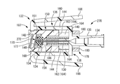
- FIGS. 7 to 13 show a male connector 120 as a second embodiment of the present invention.
- the male connector 120 includes a side hole needle 124 as a hollow needle having an opening 122 on its side.
- the axial direction means the left-right direction in FIG. 11, which is the central axis direction of the side hole needle 124.
- the tip side means the left side in FIG. 11 where the opening 122 is provided in the side hole needle 124, while the base end side means the side where the side hole needle 124 is fixed in FIG. On the right side of.
- the side hole needle 124 is a hollow needle made of a metal such as stainless steel or a hard synthetic resin, and is a tubular body having an inner hole 126 extending in the central axis direction.
- the tip of the side hole needle 124 is closed and rounded so as to be easily inserted into a disc valve 198 as a valve member of a female connector 190 described later, and the tip surface 128 of the side hole needle 124 is formed by a curved surface. It is configured.
- An opening 122 that opens in the direction perpendicular to the axis (side) is provided at the tip of the side hole needle 124, and an inner hole 126 communicates with the external space through the opening 122.
- a pair of openings 122, 122 are provided on both sides in one direction perpendicular to the axis (both sides in the direction orthogonal to the paper surface in FIG. 11).
- the male connector 120 includes a needle hub portion 130 that fixedly supports the side hole needle 124, and has a male connector housing 132 fixedly provided to the side hole needle 124.
- the male connector housing 132 is a substantially cylindrical member made of hard synthetic resin or the like as a whole, and a female luer part 134 having a substantially cylindrical shape is provided at the base end portion.
- a luer lock type or luer slip type syringe or connector as an external flow path provided at an end of a flow path extending from a bag in which a chemical solution or the like is enclosed can be connected. ..
- a substantially cylindrical needle hub portion 130 protruding toward the tip side is provided substantially coaxially, and the proximal end portion of the side hole needle 124 is substantially press-fitted into the needle hub portion 130.
- the side hole needles 124 are fixedly supported by the needle hub portion 130 and by extension, the male connector housing 132 by being inserted in the state and adhered or welded as necessary.
- the female luer portion 134 and the inner hole 126 of the side hole needle 124 communicate with each other, and the external flow path is connected to the side hole needle 124 via the female luer portion 134.
- the male connector housing 132 is formed as an integrally molded product including the needle hub portion 130 and the female luer portion 134.
- the inner diameter of the female luer portion 134 is reduced toward the tip side, and the inner diameter of the side hole needle 124 is made substantially equal to the tip end side. Further, on the outer peripheral surface of the axially intermediate portion of the female luer portion 134, a tapered surface 135 whose outer diameter size gradually decreases toward the tip side is formed.
- the male connector housing 132 integrally includes an outer cylindrical portion 136 that is arranged substantially coaxially with the side hole needle 124 so as to be separated from the outer peripheral side.
- the outer tubular portion 136 has a generally bottomed tubular shape that opens to the tip side as a whole, and a substantially circular bottom plate portion 138 that extends in the direction perpendicular to the axis is provided at the base end of the outer tubular portion 136. There is.
- the outer peripheral portion of the bottom plate portion 138 has a substantially annular shape and the inner peripheral portion has a substantially cross shape, and they are mutually orthogonal in two directions perpendicular to the axis (vertical direction in FIG. 11 and direction orthogonal to the paper surface).
- a pair of base end wall portions 140, 140 orthogonal to each other is provided. Since the base end wall portions 140, 140 are orthogonal to each other, the bottom plate portion 138 has substantially fan-shaped insertion holes 142 whose peripheral length around the central axis is smaller than 1/4 circumference at substantially equal intervals in the circumferential direction. Four are provided separately.
- the female luer part 134 projects toward the base end side from the intersection of the base end wall parts 140, 140, which is the central part of the bottom plate part 138, and the needle hub part 130 projects toward the distal end side. ..
- the outer cylindrical portion 136 is provided with a notch 143 that opens to the tip side and penetrates in the thickness direction.
- the outer tubular portion 136 is provided with four notches 143 in the circumferential direction over substantially the entire axial length from the tip to the base end portion. These notches 143 are adjacent to each other in the vertical direction (vertical direction in FIG. 9) as compared with the circumferential dimension between the notches 143 and 143 adjacent to each other in the width direction (horizontal direction in FIG. 9) of the male connector housing 132.
- the circumferential dimension between the matching notches 143 and 143 is larger. Due to these notches 143, the peripheral wall forming the outer tubular portion 136 is divided into four.
- a pair of flexible walls 144 and 144 having a reduced circumferential dimension and being easily elastically deformed in the radial direction are provided on both sides in the vertical direction of the outer tubular portion 136, and the outer tubular portion 136 is also provided.
- a pair of wall portions 146, 146 having a circumferential size larger than that of the flexible wall portion 144 and a larger radial deformation strength are provided on both sides in the width direction.
- fitting projections 148, 148 as connection locking portions projecting to the inner peripheral side are formed at the tips of the flexible wall portions 144, 144.
- a restraining member 150 that is movable in the axial direction with respect to the side hole needle 124 and the outer tubular portion 136 is provided between the side hole needle 124 and the outer tubular portion 136 in the radial direction.
- the restraint member 150 of the present embodiment has a substantially cylindrical shape as a whole, and is fitted onto the side hole needle 124.
- the outer diameter dimension of the restraint member 150 is substantially equal to or slightly smaller than the inner diameter dimension of the male connector housing 132, and is substantially constant over substantially the entire axial length.
- a cylindrical tip protrusion 151 having a relatively large inner diameter is formed at the tip of the restraint member 150, and a substantially annular large-diameter recess having an inner peripheral portion of the tip protrusion 151 and opening to the tip side. 152 is formed. This makes it difficult for the user's finger to touch the cover valve body 170 described later.
- the tip diameter of the tip projection 151 is preferably small so that it is difficult for a finger to be inserted.
- the inner diameter of the large-diameter recess 152 is larger than the outer diameter of the male screw portion 208 on the outer peripheral surface of the small-diameter cylindrical portion 206 of the female connector 190 described later.
- the inner peripheral edge of the large-diameter recess 152 is provided with a tubular portion 154 that projects toward the tip side, and the proximal end of the tubular portion 154 has a substantially annular inner circumferential projection that projects toward the inner circumferential side.
- a section 156 is provided.
- a substantially columnar space surrounded by the cylindrical portion 154 and the inner circumferential protrusion 156 is a storage area 158 for storing a cover valve body 170 described later. Therefore, the cover valve body 170 accommodated in the accommodation area 158 is movable in the axial direction with respect to the side hole needle 124 together with the restraining member 150.
- a base end side protruding portion 160 having a substantially cylindrical shape is formed on the base end side of the inner peripheral protruding portion 156.
- the base end side protruding portion 160 is formed substantially coaxially with the inner hole of the inner peripheral protruding portion 156 and the large diameter recessed portion 152, and the base end side protruding portion 160 and the large diameter recessed portion 152 form the inner peripheral protruding portion. It communicates through the inner hole of 156.
- the inner diameter of the base end side protrusion 160 is larger than the inner diameter of the inner peripheral protrusion 156, and is substantially equal to or slightly smaller than the outer diameter of the female luer portion 134 at the tip.
- the restraint member 150 is formed with a notch 162 that extends in the thickness direction from the peripheral wall (proximal end side protrusion 160) so as to extend from the proximal end toward the distal end side.
- the notch 162 is formed with an axial dimension shorter than that of the base end side protrusion 160, and the inside and outside of the restraint member 150 are communicated in the radial direction through the notch 162.
- the notches 162 are provided at circumferential positions corresponding to the base end wall portion 140 of the outer tubular portion 136 in the male connector housing 132, and are formed at four locations in the circumferential direction at substantially equal intervals. Has been done. As a result, in the base end portion of the restraint member 150, the annular peripheral wall (base end side protruding portion 160) is substantially divided into four, and four leg portions 164 are formed so as to be separated from each other in the circumferential direction.
- each leg portion 164 is a shape substantially corresponding to the insertion hole 142 provided in the bottom plate portion 138 of the outer tubular portion 136, and has a fan shape with a circumferential length around the central axis smaller than 1/4 round. Has been done.
- outer diameter dimension (outer diameter dimension of a virtual annular surface connecting the outer peripheral surfaces of the respective leg portions 164) is reduced at the base end portion of each leg portion 164, and the outer diameter dimension of the reduced portion is reduced.
- a positioning recess 166 extending in the circumferential direction is provided on the outer peripheral surface.
- annular fitting recess 168 extending over the entire circumference in the circumferential direction is formed on the outer peripheral surface of the tip portion (tip projecting portion 151) of the restraining member 150.
- the fitting recess does not have to be provided over the entire circumference in the circumferential direction, but may be provided on both sides in the vertical direction corresponding to the fitting projections 148, 148 of the male connector housing 132.
- a cover valve body 170 made of an elastic body such as rubber or elastomer is arranged in the accommodating region 158 of the restraining member 150 having the above structure. That is, the holding member that holds the cover valve body 170 is configured by the restraining member 150.
- the cover valve body 170 has a solid cylindrical shape or a disk shape (disk shape) as a whole, and has an insertion recess 172 extending from the approximate center of the base end side end surface to the distal end side.
- the insertion recess 172 has a circular hole shape that extends in an inner diameter smaller than the outer diameter of the side hole needle 124 substantially corresponding to the tip portion of the side hole needle 124, and is linear in the axial direction from the opening on the proximal end side.
- the tip side of the insertion recess 172 is tapered to have a small diameter, and the tip (bottom surface) of the insertion recess 172 is located at an axially intermediate portion of the cover valve body 170 without penetrating the cover valve body 170. is doing.
- a slit 173 extending from the bottom surface (the deepest portion) of the insertion recess 172 to extend through the tip side in the axial direction is formed. That is, it can be understood that the insertion recess 172 and the slit 173 form a slit that penetrates the entire cover valve body 170 in the axial direction.
- the slit 173 is not specifically limited to a one-letter slit, a radial slit, a pin hole slit, or the like, but is held in a closed state by the elasticity of the cover valve body 170.
- the tip portion of the side hole needle 124 is inserted and accommodated in the insertion concave portion 172, and the inner peripheral surface of the insertion concave portion 172 of the cover valve body 170 elastically moves with respect to the outer peripheral surface of the side hole needle 124.
- the opening 122 is sealed by being closely attached.
- the insertion recess 172 is formed deeper than the tip of the side hole needle 124, and a gap for accommodating variations in the tip position of the side hole needle caused by manufacturing tolerances, assembly errors, etc. is formed in the insertion recess 172. It is set on the bottom.
- the side hole needles 124 affect the cover valve body 170, and for example, the tip end surface of the side hole needles 124 is pressed against the bottom surface of the insertion recess 172 or reaches the slit 173. It is possible to prevent such a problem that the slit 173 of the valve body 170 is opened.
- the tip end surface 174 of the cover valve body 170 is deformed by inserting the side hole needle 124, which will be described later, from the outer peripheral portion. Also has a central projecting shape projecting toward the tip side in the central portion, and is a generally chevron-shaped tip surface 174 having a substantially rotationally symmetrical shape around the central axis.
- the central portion 174a near the apex of the chevron-shaped tip surface 174 has its center of curvature set to the base end side of the tip surface 174. It is a curved surface that is convex toward the tip side.
- the outer peripheral portion 174b which is a region that extends from the central portion 174a toward the outer periphery to the hem of the mountain-shaped tip surface 174, has its center of curvature set to the tip side of the tip surface 174, and thus the tip end side.
- the concave portion is a curved inclined surface that faces away from the central portion 174a.
- the curved surfaces of the central portion 174a and the outer peripheral portion 174b do not have to have a single arc shape, and the respective radii of curvature Ra and Rb may change in multiple steps or gradually. Further, it is desirable that the tip end surface 174 of the chevron has a surface shape that is smoothly connected without any break points, and that both curved surfaces of the central portion 174a and the outer peripheral portion 174b are smoothly connected with a common tangent line. Is desirable. In addition, it is preferable that the radii of curvature of the central portion 174a and the outer peripheral portion 174b of the front end surface 174 are set to satisfy Ra ⁇ Rb.
- the radial width dimension of the outer peripheral portion 174b of the tip end surface 174 be made larger than the radial dimension of the central portion 174a so that the concave curved surface as a whole is provided with a sufficient width.
- the outer peripheral surface 175 of the cover valve body 170 of the present embodiment has a cylindrical shape extending from the outer peripheral end of the outer peripheral portion 174b, which is the outer peripheral edge of the front end surface 174, toward the base end side in the axial direction.
- a step surface 175a is formed which is located in the axial middle portion of the cylindrical outer peripheral surface 175 and is located closer to the tip end side than the center thereof and which spreads in the radial direction.
- the tip side of the step surface 175a is a tip side outer peripheral surface 175b having a small diameter
- the base end side of the step surface 175a is a base end side outer peripheral surface 175c having a large diameter. It has a stepped cylindrical shape.
- the insertion recess 172 extending from the base end surface of the cover valve body 170 toward the tip end side in the axial direction has a depth reaching beyond the step surface 175a and reaching the inner peripheral side of the tip end side outer peripheral surface 175b, or The depth is set so as to reach beyond the tip-side outer peripheral surface 175b and reach the inner peripheral side of the outer peripheral portion 174b of the tip surface 174.
- the tip of the side hole needle 124 inserted into the insertion recess 172 may be located on the inner peripheral side of the base end side outer peripheral surface 175c of the cover valve body 170, but in the present embodiment, the step surface 175a. And reaches the inner peripheral side of the tip side outer peripheral surface 175b.
- the cover valve body 170 is assembled in a state of being fitted into the accommodation area 158 of the restraining member 150, and the base end surface of the cover valve body 170 is overlapped with the bottom surface of the accommodation area 158.
- An outer peripheral surface 175c of the cover valve body 170 on the base end side is overlapped with an inner peripheral surface of the accommodation region 158.
- the step surface 175a of the cover valve body 170 is located at substantially the same axial position as the protruding front end surface of the cylindrical portion 154 projecting in the front end protruding portion 151 of the restraining member 150.
- a hard annular member 176 is externally attached to the tubular portion 154.
- the annular member 176 is externally inserted into the tubular portion 154 in a substantially press-fitted state, and is fixed by adhering or welding as necessary.
- the tip end portion of the annular member 176 is bent toward the inner peripheral side, and on the tip end side of the tubular portion 154, an annular pressing projection 177 is formed that protrudes further toward the inner peripheral side than the tubular portion 154. ..
- the inner surface of the pressing protrusion 177 on the axially proximal end side is superposed on the step surface 175a of the cover valve body 170, and the protruding front end surface of the pressing protrusion 177 on the inner peripheral side is covered by the cover valve body 170.
- the outer peripheral surface 175b on the distal end side is disposed so as to abut or face it with a gap.
- the pressing protrusion 177 is located on the step surface 175a of the outer peripheral surface 175 of the cover valve body 170, and deformation of the cover valve body 170 toward the tip side is less likely to occur.
- the annular member 176 is externally fixed to the tubular portion 154 of the restraint member 150, and the holding projection 177 of the annular member 176 covers the outer peripheral portion of the cover valve body 170 from the tip.
- the cover valve body 170 is prevented from coming off from the restraining member 150, and the tubular portion 154 superposed on the outer peripheral surface of the cover valve body 170 is reinforced.
- the tip surface 174 of the cover valve body 170 projects toward the tip side in the axial direction.
- the projecting end (the apex of the central portion 174 a) of the tip surface 174 of the cover valve body 170 does not reach the tip of the restraint member 150, but is housed inside the tip projection 151 of the restraint member 150.
- the cover valve body 170 is preferably compressed in the radial direction by the tubular portion 154 and / or the annular member 176.
- the outer diameter dimension of the cover valve body 170 on the proximal side of the stepped surface 175a is larger than the inner diameter dimension of the tubular portion 154.
- the outer diameter dimension in the portion where the tip side outer peripheral surface 175b is formed is slightly smaller than the inner diameter dimension of the pressing protrusion 177, and is smaller than the step surface 175a of the cover valve body 170.
- the tip side part is not compressed in the radial direction.
- the cover valve body 170 is preferably compressed in the axial direction by the inner peripheral projection 156 and the portion of the annular member 176 that is bent toward the inner peripheral side (holding projection 177).
- the opening 122 of the side hole needle 124 can be more reliably closed by the cover valve body 170. That is, in the present embodiment, in the restraint member 150 that covers the outer periphery of the cover valve body 170, the outer peripheral wall portion that covers the outer periphery of the cover valve body 170 is configured by the tubular portion 154, and the bottom that covers the bottom surface of the cover valve body 170. It can be understood that the wall portion is constituted by the inner peripheral protrusion 156.
- the restraining member 150 having the above-described structure and the male connector housing 132 having the side hole needles 124 are assembled together. That is, the base end wall portion 140 of the male connector housing 132 is inserted in alignment with the notches 162 provided at the base end portion of the restraining member 150 in the circumferential direction, and the base end of each notch 162 is inserted. Closing the side opening with the lid member 178 can prevent the male connector housing 132 from falling off from the restraining member 150. In other words, the lid member 178 is assembled to the proximal end of the proximal projection 160 of the restraining member 150, and the proximal opening of the notch 162 is closed by the lid member 178.
- the lid member 178 of this embodiment is a substantially annular member as a whole, as shown in FIGS. 10 and 13.
- the lid member 178 is provided with a positioning projection 180 projecting toward the inner peripheral side at a circumferential position corresponding to the notch 162 in the restraining member 150, and is provided at the base end portion of the restraining member 150 in the lid member 178.
- the positioning protrusion 182 is formed at a position corresponding to the positioning recess 166. Then, the lid member 178 is externally inserted to the portion of the restraining member 150 at the base end portion having the reduced outer diameter dimension, the positioning protrusion 180 is inserted into the notch 162, and the positioning protrusion 166 is inserted into the positioning recess 166.
- the lid member 178 is assembled to the restraining member 150 in a state of being positioned in the axial direction and the circumferential direction.
- the minimum inner diameter of the lid member 178 (the inner diameter of an imaginary annular surface connecting the inner peripheral surfaces of the positioning protrusions 180) is the maximum outer diameter of the female luer portion 134 (the outer diameter of the proximal opening).
- the size is larger than the size), and the lid member 178 can be externally inserted to the base end portion of the restraining member 150 in a state where the restraining member 150 and the male connector housing 132 are assembled.
- the lid member 178 is assembled to the base end portion (base end side protrusion 160) of the restraint member 150 and the base end side opening of the notch 162 is closed, so that the restraint member 150 is provided.
- a substantially rectangular guide window 184 that penetrates inside and outside and extends in the axial direction is formed, and the proximal end wall portion 140 of the male connector housing 132 is inserted into the guide window 184.
- the side hole needle 124 and the needle hub portion 130 are inserted into the proximal end side protruding portion 160, and the side hole needle 124 inserts the inner peripheral protruding portion 156. Penetrates. Further, the distal end portion of the female luer portion 134 is inserted into the proximal end side protruding portion 160, and the proximal end portion of the female luer portion 134 projects from the proximal end side protruding portion 160 toward the proximal end side.
- the tip surface 128 of the side hole needle 124 is located in the middle portion of the cover valve body 170 in the axial direction (the penetrating direction of the slit 173), and the tip of the side hole needle 124 is located.
- the surface 128 is covered with a cover valve body 170.
- the outer periphery of the cover valve body 170 is covered by the tubular portion 154 and the annular member 176 of the restraining member 150 over the entire circumference. ing.
- the side opening (opening 122) of the inner hole 126 of the side hole needle 124 is covered and closed by the cover valve body 170.
- a coil spring 186 is provided between the restraint member 150 and the male connector housing 132, which are assembled with each other, as a biasing means for biasing the restraint member 150 toward the distal end side with respect to the male connector housing 132. .. Specifically, the coil spring 186 is externally inserted into the needle hub portion 130 and accommodated in the proximal end side protrusion 160, and the tip of the coil spring 186 is fixed to the inner peripheral protrusion 156 of the restraining member 150. In addition, the proximal end of the coil spring 186 is fixed to the distal end of the female luer portion 134 and the proximal end wall portions 140, 140.
- the fitting protrusion 148 provided in the male connector housing 132 is fitted into the fitting recess 168 provided in the restraining member 150.
- the male connector housing 132 and the restraining member 150 are locked to each other in the axial direction by the concave and convex fitting of the fitting convex portion 148 and the fitting concave portion 168 in the radial direction, and the restraining member 150 with respect to the male connector housing 132.
- the axial movement of is restricted.
- the side opening 122 of the side hole needle 124 is held in a sealed state by the cover valve body 170.
- the movement restricting mechanism that locks the cover valve body 170 at the position that seals the opening 122 by locking with the restraining member 150 is the relationship between the fitting protrusion 148 and the fitting recess 168. It is configured to include a stop mechanism.
- the fitting convex portion and the fitting concave portion may be provided on opposite sides of each other, that is, the fitting convex portion may be provided on the restraining member and the fitting concave portion may be provided on the male connector housing.
- the restraint member 150 In the initial state, the restraint member 150 is located on the most distal end side with respect to the male connector housing 132, and the base end wall portions 140, 140 of the restraint member 150 are located on the most proximal end side in each guide window 184. Then, it abuts or is slightly separated from the lid member 178. In such an initial state, the coil spring 186 has a substantially natural length or is in a slightly compressed state. Therefore, in the present embodiment, the defining means for defining the moving end of the cover valve body 170 toward the distal end side is configured such that the fitting convex portion 148 and the fitting concave portion 168 are fitted in the concave-convex shape and the base end wall in the guide window 184.
- the positioning means 187 which is configured by at least one of the contact between the portion 140 and the lid member 178, and elastically positions the cover valve body 170 at the tip portion of the side hole needle 124, is a coil that is a biasing means.
- the spring 186 and the regulating means are included.
- the male connector housing 132 is provided with a releasing mechanism capable of releasing the locking mechanism of the fitting convex portion 148 and the fitting concave portion 168 as the movement limiting mechanism.
- an operation piece 188 as an operation portion that protrudes to the outer peripheral side is provided continuously from the fitting convex portion 148 provided at the tip of the flexible wall portion 144.
- the operation piece 188 of the present embodiment projects from the distal end of the flexible wall portion 144 to the outer peripheral side, curves from the outer peripheral end to the base end side, and extends to the base end side.
- the operation piece 188 extends in a direction inclining toward the outer peripheral side toward the base end side.
- the locking mechanism between the fitting convex portion 148 and the fitting concave portion 168 is configured to include the operation portion (operation piece 188) as the release mechanism.
- the fluid passage is brought into a communicating state by inserting the side hole needle 124 into the female connector which is a mating partner and connecting the side hole needle 124.
- the female connector that can be connected to the male connector 120 of the present embodiment is not limited in any way, but a specific example of the female connector is shown in FIG.
- the female connector 190 of this embodiment is configured by assembling a disc valve 198 as a valve member to a female connector housing including a base member 192, a lower cover member 194 and an upper cover member 196. .. That is, the upper and lower cover members 196 and 194 are fixed to the base member 192 with the disc valve 198 sandwiched therebetween, and the disc valve is provided in the opening portion of the female luer part 200 constituted by the upper and lower cover members 196 and 194. 198 are arranged.
- the disc valve 198 As the holding structure by the disc valve 198 and its female connector housing, those known in, for example, JP-A-2013-198755 and JP-A-2019-72648 can be appropriately adopted. That is, for example, the disc valve 198 is provided with a slit 202 penetrating in the thickness direction in a disk-shaped central portion 198a which has a substantially constant thickness dimension and spreads in the direction perpendicular to the axis. In the initial state, the slit 202 is provided. Is blocked. It should be noted that the shape of the slit 202 is not limited, and various shapes such as a single letter shape, a cross shape, and a radial shape can be adopted.
- a three-pronged shape extending from the center to three circumferential directions at substantially equal intervals is used. It is said that By forming the slit 202 with a plurality of slits, such as a three-pronged slit, or by increasing the width, the deformability of the disc valve 198 is increased, the insertion resistance is small, and the operability can be improved. By reducing the width of the slit 202 to such an extent that the side hole needle 124 can be inserted, the operability is reduced, but the exposure risk can be suppressed. To reduce the exposure risk, it is possible to use pinholes instead of slits.
- locking grooves are formed on both the inner surface and the outer surface of the central portion 198a on the outer peripheral side and extend in the circumferential direction, respectively.
- the thickness of the disc valve 198 is made thin by the engagement grooves on the inner and outer surfaces, and an annular or tubular support portion 198b is formed on the outer peripheral side of the thin holding portion.
- the support portion 198b is sandwiched by the upper and lower cover members 196 and 194, and the inner and outer locking claws provided on the upper and lower cover members 196 and 194 are provided. Are locked in locking grooves inside and outside the disc valve 198.
- annular step surface 204 is provided on the outer peripheral surface of the upper cover member 196 of the present embodiment, and the female connector tip side (right side in FIG. 15), which is the connection tip side of the step surface 204, has a small diameter.
- the cylindrical portion 206 is provided with a male screw portion 208 on the outer peripheral surface of the small diameter cylindrical portion 206. With this male screw portion 208, for example, a syringe with a lock or the like can be connected to the small-diameter cylinder portion 206 of the female connector 190.
- physiological saline or the like is enclosed. By connecting the prepared syringe or the like and injecting physiological saline or the like into the patient's body, the drug solution remaining in the female connector 190 can be injected into the patient.
- a flange-like portion 210 as an outwardly projecting portion with which the above-mentioned male connector 120 can be locked in the axial direction is provided so as to project more outward than the male screw portion 208.
- the female connector housing has a step surface 204 at an intermediate portion in the axial direction, and the front end side of the female connector with respect to the step surface 204 is a small diameter portion having an external thread portion 208 formed on the outer peripheral surface.
- the female connector base end side with respect to the step surface 204 is a large-diameter, substantially-cylindrical, large-diameter cylindrical portion 212.
- An annular flange-shaped portion 210 projecting to the outer peripheral side is formed at the female connector tip portion of the large-diameter cylindrical portion 212.
- the flange-shaped portion 210 it suffices for the flange-shaped portion 210 to be capable of locking the male connector 120 (the fitting convex portion 148 of the male connector 120 in the present embodiment) in the axial direction, and for example, is formed so as to partially project in the circumferential direction. May be formed, and may be formed so as to project at a position closer to the front end side of the female connector than the stepped surface 204, or may be provided with a groove for fitting with the fitting convex portion 148 instead of the flange-shaped portion 210. ..
- the fluid flow path 216 is brought into communication. That is, after the small-diameter cylindrical portion 206 of the female connector 190 is inserted into the large-diameter concave portion 152 of the male connector 120, the proximal end portions of the operation pieces 188 and 188 that form the release mechanism are pressed toward the inner peripheral side, whereby the flexible structure is obtained.
- the wall portion 144 and the fitting convex portion 148 are elastically deformed and / or displaced to displace the fitting convex portion 148 to the outer peripheral side. As a result, the engagement between the fitting convex portion 148 and the fitting concave portion 168 is released, and the restraining member 150 is movable in the axial direction with respect to the male connector housing 132.
- the small-diameter cylindrical portion 206 can be inserted into the large-diameter concave portion 152 by inserting at least a part of the base end portion of the small-diameter cylindrical portion 206 in the axial direction. For example, the entire length of the small-diameter cylindrical portion 206 can be inserted. It is not necessary to insert the cover valve body 170 and the disc valve 198 until they come into contact with each other. This operation prevents the restraint member 150 from unintentionally coming into contact with the small-diameter tubular portion 206 and being moved to the proximal end side in a state where the engagement between the fitting convex portion 148 and the fitting concave portion 168 is released. However, the small-diameter cylindrical portion 206 may be inserted into the large-diameter concave portion 152 after the engagement between the fitting convex portion 148 and the fitting concave portion 168 is released.
- the tip end surface of the female connector 190 (the surface of the upper cover member 196 and the disc valve 198) and the large-diameter recess 152 in the restraint member 150 are formed.
- the front end surface (the surface of the annular member 176 and the cover valve body 170) is brought into contact, and the female connector 190 is axially pushed into the male connector housing 132. Due to the pushing force of the female connector 190, the restraining member 150 including the cover valve body 170 together with the female connector 190 resists the biasing force of the coil spring 186 (while the coil spring 186 is being compressed) with respect to the side hole needle 124.
- the female connector 190 and the restraining member 150 move straight, that is, by linear translational movement without rotation. It should be noted that, for example, by pressing the proximal end portions of the operation pieces 188, 188 toward the inner peripheral side with one hand, the female connector 190 and the restraining member 150 can be moved toward the proximal end side with the other hand. You can
- the side hole needle 124 is inserted into both the slits 173 and 202 of the cover valve body 170 and the disc valve 198, and the opening 122 of the side hole needle 124 is positioned inside the female luer part 200 of the female connector 190. Then, the flow path of the male connector 120 and the flow path of the female connector 190 are communicated with each other to form a fluid flow path 216. As a result, a drug solution such as an anticancer agent enclosed in a bag connected to the female luer part 134 of the male connector 120 can be injected into the blood vessel of the patient through a catheter or the like communicating with the fluid flow path 216.
- the annular member 176 and the upper cover member 196 which are hard members, come into contact with each other, so that the pushing force of the female connector 190 is restrained.
- the member 150 is reliably transmitted, and the movement of the female connector 190 and the restraining member 150 toward the proximal end side can be stably achieved.
- the base end wall portion 140 of the male connector housing 132 is inserted into the guide window 184 of the restraint member 150, the axial movement of the restraint member 150 with respect to the male connector housing 132 can be guided by the guide window 184. ..
- the outer diameter of the restraining member 150 and the inner diameter of the outer tubular portion 136 are substantially equal to each other, even if the outer peripheral surface of the restraining member 150 and the inner circumferential surface of the outer tubular portion 136 contact each other, the male connector housing Movement of the restraining member 150 in the direction perpendicular to the axis with respect to 132 is prevented, and the movement in the axial direction is guided. That is, it can be understood that the outer peripheral surface of the restraint member 150 and the inner peripheral surface of the outer tubular portion 136 also constitute the guide means, and the guide portion is formed by the outer peripheral surface of the base end side protruding portion 160 of the restraint member 150. It can be understood that is configured.
- the wall portions 146 and 146 of the outer tubular portion 136 have a larger circumferential dimension than the upper and lower flexible wall portions 144 and 144, so that the area and deformation strength of the inner peripheral surface are secured, and The guiding action of the restraint member 150 by the tubular portion 136 can also be improved.
- the distal end surface 174 of the cover valve body 170 of the male connector 120 has the specific shape including the central portion 174a having the convex curved shape and the outer peripheral portion 174b having the concave curved shape as described above.
- the cover valve body 170 and the disc valve 198 are superposed with each other without a gap. That is, as shown in FIGS. 16A and 16B, when the side hole needle 124 is inserted into the disc valve 198 of the female connector 190, friction resistance of the side hole needle 124 or the like causes the disc valve 198 to move.
- the central portion 198a is deformed so as to be recessed inward in the axial direction of the female connector 190, and the outer surface of the central portion 198a of the disk valve 198, which was a flat surface in the initial shape, is deformed so as to be recessed into a substantially mortar shape. ..
- the outer surface of the central portion 198a of the disc valve 198 of the female connector 190 was supported by the inner and outer locking claws of the female connector housing. It elastically deforms with a curved shape that is convex toward the outer surface side from the outer peripheral edge toward the center. Therefore, since the cover valve body 170 of the male connector 120 has the concave curved outer peripheral portion 174b on the distal end surface 174, the side hole needle 124 can be inserted when the male connector 120 and the female connector 190 are connected.
- the outer surface of the elastically deformed disc valve 198 substantially conforms to the shape, and the disc valve 198 can be superposed in a substantially close contact state in which a gap is suppressed.
- the central portion of the disc valve 198 of the female connector 190 the central portion of the cover valve body 170 of the male connector 120, which is superposed on the surface, of the side hole needle 124 to be inserted is easily pulled inward. Since 174a has a convex curved shape, good adhesion can be ensured when connecting the male connector 120 and the female connector 190. As a result, in the connected state of the male connector 120 and the female connector 190, the gap between the overlapping surfaces of the cover valve body 170 and the disc valve 198 can be more effectively reduced.
- the slit 202 formed in the disc valve 198 has a concave curved outer peripheral portion 174b and a curved shape when it has a slit shape in which three or more flaps, such as a three-pronged shape or a cross shape, are formed rather than a single character.
- the disk valve 198 which is elastically deformed by being easily overlapped with each other is preferable.
- the connection between the male connector 120 and the female connector 190 is released so that the fluid flow path 216 is cut off. That is, by applying an operation external force to the operation piece 188, specifically pressing the proximal end portion of the operation piece 188 to the inner peripheral side to displace the fitting convex portion 148 to the outer peripheral side, the fitting convex portion 148.
- the flange-shaped portion 210 is disengaged from the female connector 190 so that the female connector 190 can be detached from the male connector housing 132.
- the coil spring 186 elastically restores and deforms, and the restraining member 150 moves to the tip side with respect to the male connector housing 132. ..
- the tip portion of the side hole needle 124 is covered with the cover valve body 170, and the pressing force on the operation piece 188 is released, whereby the fitting convex portion 148 and the fitting concave portion 168 are locked,
- the restraint member 150 is immovable with respect to the male connector housing 132. As a result, it is possible to more reliably prevent the exposure or leakage of the chemical solution from the opening 122 of the side hole needle 124.
- the positioning means 187 for positioning the cover valve body 170 at the tip portion of the side hole needle 124 is provided, and a hard cover that covers the outer periphery of the cover valve body 170. Since the restraint member 150 and the annular member 176 are provided, the opening portion 122 of the side hole needle 124 is more surely covered by the cover valve body 170 when the female connector 190 is not connected, as in the first embodiment. By being sealed by, the exposure and leakage of the drug solution can be prevented more reliably.
- the movement restricting mechanism that restricts the movement of the restraining member 150 by locking the restraining member 150 and the male connector housing 132 is provided, the opening 122 of the side hole needle 124 is prevented. The sealed state can be stably maintained.
- the male connector 120 of the present embodiment is provided with a release mechanism (operation piece 188) for releasing the locking between the restraining member 150 and the male connector housing 132, and the female connector 190 and the restraining member 150 are connected to the base end side.
- the moving operation and the unlocking operation by the unlocking mechanism (operation piece 188) are performed separately.
- the locking between the restraining member 150 and the male connector housing 132 can be intentionally released, and the stability and reliability of the unlocking operation can be improved.
- the operation of releasing the movement restriction mechanism the operation of pushing the operation piece 188 toward the central axis
- the operation of moving the restraint member the operation of moving the restraint member 150 along the central axis
- the operating force required for each operation can be set separately. This makes it possible to achieve both the certainty of the restriction of movement of the restraint member by the movement restricting mechanism and the good movement operability of the restraint member when the movement restricting mechanism is released. Specifically, for example, it is possible to increase the locking force between the restraint member 150 and the male connector housing 132 while ensuring good movement operability of the restraint member 150. Therefore, the improvement of the operability of the moving operation and the improvement of the operability of the unlocking operation can be achieved at the same time.
- the movement of the restraint member 150 is restricted with the tip projection 151 of the restraining member 150 projecting toward the tip side of the cover valve body 170, so that the cover valve body 170 is unintentionally contacted.
- the opening 122 of the side hole needle 124 can be prevented from being opened, and the exposure and leakage of the drug solution such as the anticancer drug can be prevented.
- the restraint member 150 since the restraint member 150 is moved toward the base end side according to the guide means, the restraint member 150 can be moved while suppressing rattling with respect to the male connector housing 132.
- the guide means is configured, for example, by providing a groove portion extending in the axial direction in the male connector housing 132 and a guide piece projecting to the outer peripheral side in the restraining member 150, and sliding the guide piece in the groove portion. May be.
- the cover valve body 170 projects toward the tip side, and substantially corresponds to the disc valve 198 of the female connector 190 that deforms so as to be pulled toward the tip side when the side hole needle 124 is inserted. It is shaped.
- the cover valve body 170 and the disc valve 198 come into contact with each other without a gap, and when the side hole needle 124 is removed from the female connector 190, the cover valve body The exposure or leakage of the liquid medicine that has entered the gap between the body 170 and the disc valve 198 can be avoided.
- FIGS. 17 and 18 show a male connector 220 as a third embodiment of the present invention.
- the male connector 220 of this embodiment has the same structure as the male connector 10 of the first embodiment. That is, as shown in FIG. 19, the male connector 220 of the present embodiment covers the side hole needle 14 having the opening 12 on the side of the distal end portion of the hollow needle, and the side opening 12 to the side.
- the axial direction means the vertical direction in FIG. 18, which is the central axis direction of the side hole needle 14.
- the distal end side means the lower side in FIG. 18 where the opening 12 is provided in the side hole needle 14, and the proximal end side means the side where the side hole needle 14 is fixed.
- the upper part of the inside is denoted by the same reference numerals as those in the above-described embodiment in the drawings, and detailed description thereof will be omitted.
- the male connector housing 18 is a single member formed by integral molding, but the male connector housing 226 of the present embodiment has a structure in which a plurality of members are connected in the axial direction. Is becoming That is, in the male connector housing 226 of the present embodiment, the cylindrical peripheral wall portion 228 that covers the outer periphery of the restraining member 224 and the needle hub 230 that supports the side hole needle 14 are configured separately from each other. A cylindrical peripheral wall portion 228 is connected to the tip end side of the hub 230.
- the cylindrical peripheral wall portion 228 has a substantially cylindrical shape as a whole, and the base end portion thereof has a through window 232 that penetrates in the thickness direction of the peripheral wall and has a substantially rectangular shape in a plan view, and penetrates in the thickness direction of the peripheral wall.
- a positioning recess 234 extending from the base end to the tip side is formed with a certain axial dimension.
- the four through windows 232 are formed at substantially equal intervals in the circumferential direction, and the pair of positioning recesses 234 are opposed to each other in the radial direction at a position deviating from the through windows 232 in the circumferential direction. Has been formed.
- the peripheral wall at the base end of the cylindrical peripheral wall portion 228 is elastically deformable in the radial direction.
- the inner peripheral surface of the base end of the cylindrical peripheral wall portion 228 is provided with a tapered surface 236 that gradually increases in diameter toward the base end at a circumferential position corresponding to the through window 232. There is.
- the inner peripheral surface of the base end portion of the cylindrical peripheral wall portion 228 is provided with a portion whose inner diameter is partially increased in the circumferential direction, and the inner peripheral groove portion 238 is formed by the portion whose inner diameter is increased.
- the inner peripheral groove portion 238 has a substantially rectangular cross section, and extends from the base end to the distal end side with a certain axial dimension.
- an annular inner peripheral protrusion 240 that protrudes toward the inner peripheral side is provided at an axially intermediate portion of the cylindrical peripheral wall portion 228, and an inner peripheral protrusion 240 that extends in the axial direction is provided on the proximal end side.
- a peripheral groove portion 238 is formed.
- four inner peripheral groove portions 238 are provided and are formed at substantially equal intervals in the circumferential direction.
- a female screw portion 242 is formed on the inner peripheral surface of the distal end portion of the cylindrical peripheral wall portion 228.
- the female screw portion 242 can be screwed with the male screw portion 102 of the female connector 86 which is a connection partner.
- the needle hub 230 is configured to integrally include a female luer portion 244 to which an external flow path is connected and a needle hub portion 246 that substantially holds the side hole needle 14.
- the female luer portion 244 and the needle hub portion 246 are both substantially cylindrical in shape, and the needle hub portion 246 has a smaller diameter than the female luer portion 244, so that the female luer portion 244 has an inner peripheral side.
- the needle hub portion 246 continuously extends toward the distal end side. That is, the axially intermediate portion of the needle hub 230 has a double tubular structure in which the female luer portion 244 and the needle hub portion 246 are inserted into and out of each other, and the diameter of the female luer portion 244 and the needle hub portion 246 is the same.
- An annular recess 248 that opens toward the tip side is formed between the directions.
- an engagement protrusion 250 that protrudes toward the outer peripheral side is provided on the outer peripheral surface at the tip portion of the female luer part 244.
- the engagement protrusion 250 has a shape substantially corresponding to the through window 232, and has a substantially rectangular shape in a plan view.
- four engagement protrusions 250 are provided and are formed at positions corresponding to the through windows 232 in the circumferential direction.
- a positioning projection 252 is provided at a position outside the engagement projection 250 in the circumferential direction and projects in the outer circumferential side and extends in the axial direction.
- the positioning projection 252 corresponds to the positioning recess 234 in the circumferential direction. Is formed in position.
- the tip end surface of the engaging projection 250 is a tapered surface 254 whose projecting dimension gradually decreases toward the tip end side.
- the restraint member 224 is generally cylindrical in shape, has an annular pressing projection 256 projecting to the inner peripheral side at the tip, and projects to the outer circumferential side at the base end.
- An outer peripheral protrusion 258 is provided.
- the outer peripheral protrusion 258 is a rectangular block-shaped protrusion having a size substantially corresponding to the inner peripheral groove 238, and is formed at a position corresponding to the inner peripheral groove 238 in the circumferential direction.
- the cover valve body 222 of this embodiment has the same shape as the cover valve body 170 of the second embodiment as a whole, but in this embodiment, the bottom surface of the insertion recess 172 has a step surface 175a.
- a slit 173 is formed over the entire length of the tip end side of the stepped surface 175a at the center of the tip end portion of the cover valve body 222 at substantially the same axial position.
- the outer diameter dimension at the tip of the cover valve body 222 is slightly smaller than the inner diameter dimension of the pressing protrusion 256, and the slit 173 portion of the cover valve body 222 is compressed in the radial direction. It is supposed not to be done.
- the outer diameter dimension of the cover valve body 222 (outer diameter dimension of the proximal end side outer peripheral surface 175c) is preferably substantially equal to or slightly larger than the inner diameter dimension of the restraining member 224.
- the cover valve body 222 When assembled with the restraint member 224, the cover valve body 222 is preferably slightly compressed in the radial direction by the inner peripheral surface of the restraint member 224.
- the inner diameter dimension of the cover valve body 222 (the inner diameter dimension of the insertion recess 172) is substantially equal to or slightly smaller than the outer diameter dimension of the side hole needle 14, and the side hole needle 14 serves as the cover valve body.
- an annular convex portion may be provided on the outer surface of the cover valve body 222 so that it is slightly compressed in the radial direction by the inner peripheral surface of the restraining member 224. Further, particularly strong compression may be annularly generated on the distal end side and the proximal end side of the opening 12 of the side hole needle 14. Furthermore, an annular convex portion may be provided on the outer peripheral surface of the side hole needle 14 and / or the inner peripheral surface of the restraining member 224.
- the restraint member 224 to which the cover valve body 222 is assembled is inserted from the base end of the cylindrical peripheral wall portion 228. At that time, the outer peripheral projection 258 of the restraint member 224 is fitted into the inner circumferential groove portion 238 of the cylindrical circumferential wall portion 228, and the restraint member 224 is prevented from rotating around the central axis with respect to the cylindrical circumferential wall portion 228. Moreover, it is movable in the axial direction.
- the needle hub 230 to which the side hole needle 14 is fixed is inserted from the base end side of the tubular peripheral wall portion 228. That is, with the through window 232 of the tubular peripheral wall portion 228 and the engagement protrusion 250 of the needle hub 230 aligned in the circumferential direction, the needle hub 230 is inserted from the proximal end side opening portion of the tubular peripheral wall portion 228. By doing so, the positioning protrusion 252 enters the positioning recess 234 to prevent relative rotation between the tubular peripheral wall 228 and the needle hub 230, and the distal end of the needle hub 230 relative to the tubular peripheral wall 228 is prevented.
- the moving end is defined.
- engagement protrusion 250 enters and engages the through window 232 to prevent relative rotation between the tubular peripheral wall portion 228 and the needle hub 230, and at the same time, the needle hub 230 relative to the tubular peripheral wall portion 228.
- a moving end to the base end side is defined.
- the cylindrical peripheral wall portion 228 and the needle hub 230 are assembled in a state of being axially positioned.
- the taper surface 236 at the base end of the tubular peripheral wall portion 228 and the taper surface 254 at the tip end of the engaging projection 250 come into contact with each other.
- the base end of the cylindrical peripheral wall portion 228 is easily deformed toward the outer peripheral side.
- the female connector 86 as shown in FIG. 5 is connected from the tip side by screw feeding, so that the tip surface 174 of the cover valve body 222 is connected.
- the base end surface (upper surface in FIG. 5) of the valve member 94 is brought into contact with each other, and the side hole needle 14 is inserted into the cover valve body 222 and the valve member 94.
- the male connector housing 226 is configured by connecting the cylindrical peripheral wall portion 228 and the needle hub 230, which are separate from each other, so that the inner peripheral protrusion 240 and the outer peripheral protrusion 258 are formed. Can be easily provided inside the male connector housing 226. Further, since the inner peripheral protrusion 240 and the outer peripheral protrusion 258 are provided inside the cylindrical peripheral wall portion 228, for example, the outer peripheral protrusion 258 is pushed to the inner peripheral side from the outside and is connected to the inner peripheral protrusion 240. Unintentional disengagement is also avoided.
- FIG. 20 shows a male connector 270 as a fourth embodiment of the present invention.
- the male connector 270 of this embodiment has the same structure as the male connector 120 of the second embodiment.
- the difference from the male connector 120 of the second embodiment is that the male connector 270 of the present embodiment has a female connector 190 (see FIG. 15) that is a connection partner on the inner peripheral surface of the tip projection 151 of the restraining member 150.
- the male screw portion 208 is provided with a female screw portion 272.
- the cover valve body the cover valve body 222 having the shape of the third embodiment is adopted.
- the axial direction means the left-right direction in FIG. 20, which is the central axis direction of the side hole needle 124.
- the distal side means the left side in FIG. 20 where the opening 122 is provided in the side hole needle 124, while the proximal side means the side where the side hole needle 124 is fixed in FIG. On the right side of.
- the male connector 270 and the female connector 190 are brought close to each other, and the female screw portion 272 and the male screw portion 208 are screwed together. Then, the female connector 190 is moved in the direction of approaching the male connector 270 by screw feeding, so that the small-diameter cylindrical portion 206 of the female connector 190 enters the tip protruding portion 151.
- the moving end of the female connector 190 with respect to the male connector 270 may be, for example, the pressing projection 177 of the male connector 270 and the proximal end surface (the right end surface in FIG. 21) of the small-diameter cylindrical portion 206 contact each other, or the tip projection portion.
- the connecting portion provided on the male connector 270 and connecting to the female connector 190 is formed by the female screw portion 272.
- such a connecting portion female screw portion 272 is provided on the restraining member 150 of the male connector 270 so that the female connector 190 and the restraining member 150 of the male connector 270 are coupled to each other.
- the pressing projection 177 and the proximal end surface of the small diameter tubular portion 206 are in contact with each other.
- the tip end surface 174 of the cover valve body 222 of the male connector 270 and the base end surface of the disc valve 198 as a valve member of the female connector 190 are overlapped and project from each other. It is also possible to make the holding projection 177 smaller than the small diameter tubular portion 206 so that the holding projection 177 is inserted into the small diameter tubular portion 206.
- the operation piece 188 is operated (the operation piece 188 is pressed toward the inner peripheral side) to release the engagement between the fitting convex portion 148 and the fitting concave portion 168, and as shown in FIG.
- the male connector housing 132 is moved to the distal end side with respect to the restraining member 150 and the female connector 190 (or the restraining member 150 and the female connector 190 are opposed) against the biasing force of the coil spring 186 (while compressing the coil spring 186). (It is moved to the base end side with respect to the male connector housing 132).
- the side hole needle 124 is inserted into the cover valve body 222 and the disc valve 198, and the fluid flow path 216 is brought into communication.
- the method of connecting the male connector 270 and the female connector 190 is not limited to the above-described method.
- the operation piece 188 is operated to release the engagement between the fitting convex portion 148 and the fitting concave portion 168.
- the female screw portion 272 and the male screw portion 208 are screwed together to connect the male connector 270 and the female connector 190, and then the male connector housing 132 is moved to the tip side to cover the side hole needle 124 with the cover valve body 222 and the disc.
- the fitting protrusion 148 and the flange-shaped portion 210 may be engaged with each other while being inserted into the valve 198.
- the female screw portion 272 and the male screw portion 208 are screwed together before the side hole needle 124 is inserted into the cover valve body 222 and the disc valve 198, and the tip of the cover valve body 222 is screwed.
- the surface and the base end surface of the disc valve 198 are brought into contact with each other. That is, since the side hole needle 124 is inserted and removed with the cover valve body 222 and the disc valve 198 superposed on each other, the cover valve body 222 and the disc valve 198 are inserted and removed when the side hole needle 124 is inserted and removed. A gap is prevented from being generated between them. As a result, leakage or exposure of the drug solution through the gap can be effectively avoided.
- the restraint member 150 and the female connector 190 are connected to each other when the male connector housing 132 is moved, the restraint member 150 is removed from the restraint member 150 during the operation of engaging the fitting convex portion 148 with the flange-shaped portion 210.
- the female connector 190 does not unintentionally come off, and the engaging operation of the fitting convex portion 148 and the flange portion 210, that is, the male connector housing 132 is moved to cover the side hole needle 124 with the valve body 222 and the disc valve.
- the operation of inserting into 198 can be performed more reliably.
- the central axes of the male connector 270 and the female connector 190 are aligned, and the side hole needle 124 is inserted into the slit 202 at the center of the disc valve 198. It can be inserted more reliably. As a result, unintended deformation of the disc valve 198 can also be suppressed, and a chemical liquid can be prevented from leaking out or being exposed due to the formation of a gap between the cover valve body 170 and the disc valve 198.
- the female luer portion 20, the outer tubular portion 36, and the lock portion 42 are integrally formed in the male connector 10 (male connector housing 18), and when the female connector 86 is screwed, The entire male connector 10 is adapted to rotate around the central axis with respect to the female connector 86.
- the cylindrical peripheral wall portion 228 and the needle hub 230 are formed as separate bodies in the male connector housing 226 and are not rotatable, but are limited to these aspects. is not.
- the female luer portion 282 and the lock portion 284 may be formed separately so as to be relatively rotatable around the central axis.
- a tubular body 286 is fixed to the proximal end side of the lock portion 284, and the distal end portion of the female luer portion 282 is inserted into the tubular body 286 so as to be relatively rotatable.
- a ratchet mechanism 288 is formed between the female luer portion 282 and the tubular body 286.
- the ratchet mechanism 2808 when the female luer portion 282 is rotated clockwise in FIG. 24, the projections of the female luer portion 282 shown in the upper and lower portions in FIG. 24 are projected in the tubular body 286. It hits the tip end surface of the flexible piece and is prevented from rotating by the tubular body 286. Therefore, the right rotational force applied to the female luer portion 282 is directly transmitted from the tubular body 286 to the lock portion 284, and the female luer portion 282 and the tubular body 286 and the lock portion 284 rotate together. ..
- the female luer portion 282 when the female luer portion 282 is rotated counterclockwise in FIG. 24, the projection of the female luer portion 282 abuts against the tip end portion of the flexible piece of the tubular body 286 from the side, so that the flexible piece escapes. As described above, the female luer portion 282 is allowed to rotate relative to the tubular body 286 by elastic deformation. Therefore, the left rotational force to the female luer portion 282 is not transmitted to the tubular body 286 and the lock portion 284, and the female luer portion 282 and the tubular body 286 run idle.
- the tubular body 286 and the lock part 284 are gripped to rotate the female luer part 282 in the clockwise direction. With the rotation blocked, the connector can be rotationally locked and connected to the female luer part 282.
- the member forming the female luer portion 292 and the member forming the lock portion 294 are separate bodies, and the ratchet mechanism 296 is formed between both members. Has been done. Also in the male connector 290 of this aspect having such a structure, the same effect as the male connector 280 shown in FIGS. 23 and 24 can be exhibited.
- the O-ring 304 and the cover valve body 302 as an annular seal part that is mounted on the side hole needle 14 in an externally inserted state.
- a restriction member 306 for restricting the deformation of the proximal end surface of the may be provided.
- the O-ring 304 is provided on the inner peripheral side of the base end surface of the cover valve body 302, and the annular limiting member 306 is provided so as to cover the base end side from the outer peripheral side of the O-ring 304. There is. As a result, the limiting member 306 and the outer peripheral portion of the base end surface of the cover valve body 302 are in contact with each other.
- the limiting member 306 can be assembled to the restraining member 224, the side hole needle 14, or the like by being inserted into the restraining member 224 in a press-fitted state or fixed by adhesion, welding, or the like.
- the O-ring 304 is compressed in the radial direction between the restriction member 306 and the side hole needle 14, so that the cover valve body 302 and the outer peripheral surface of the side hole needle 14 are sealed. ..
- the tip of the coil spring 82 is fixed to the base end surface of the limiting member 306.
- the O-ring 304 By providing the O-ring 304 as described above, even if a gap occurs between the side hole needle 14 and the cover valve body 302 due to the insertion and removal of the side hole needle 14 into and from the cover valve body 302, etc. Leakage and exposure of drug solution through the can be prevented. Further, since the restricting member 306 that comes into contact with the base end surface of the cover valve body 302 is provided, the deformation of the base end surface of the cover valve body 302 is suppressed, and the gap between the cover valve body 302 and the side hole needle 14 is reduced. Occurrence can be prevented.
- the O-ring 304 and the limiting member 306 are provided at the same time, but they may be provided individually.
- the seal portion does not need to be an O-ring, and for example, a tubular portion integrally protruding from the cover valve body to the base end side is a side portion.
- An annular member which is provided in a state of being externally inserted into the hole needle, may be externally fitted and fixed to the side hole needle so as to tighten the tubular portion.
- it is preferable that the annular portion is provided on the inner peripheral surface of the tubular portion so that the tubular portion comes into line contact with the outer peripheral surface of the side hole needle. As a result, it is possible to avoid an increase in frictional resistance with the seal portion when the side hole needle is inserted and removed.
- the restricting member may partially cover the base end face of the cover valve body as in the present embodiment, or for example, may cover substantially the entire base end face of the cover valve body. It may be a substantially annular member that covers.
- the limiting member is preferably made of a material harder than the cover valve body, and more preferably made of metal or hard synthetic resin, for example.
- the tip ends of the cover valve bodies 74 and 222 are exposed from the male connector housings 18 and 226 to the tip side and are exposed to the outside.
- the male connector 310 shown in FIG. the cover portion 316 protruding from the cylindrical peripheral wall portion 314 of the male connector housing 312 to the tip end side may be provided so that the tip end of the cover valve body 318 is covered with the cover portion 316.
- the cover portion 316 of this aspect has a larger diameter than the cylindrical peripheral wall portion 314, and the base end of the cover portion 316 is connected by the annular connecting wall portion 320 at the axially intermediate portion of the cylindrical peripheral wall portion 314. There is.
- the cover portion 316 may be separable from the cylindrical peripheral wall portion 314.
- the cover valve body 330 shown in FIG. 29 can also be adopted. That is, the cover valve body 330 is provided with the front end side slit 332 and the base end side slit 334, and the extending directions of these slits 332 and 334 are different. In particular, in this aspect, both slits 332 and 334 extend in directions orthogonal to each other. This can effectively prevent leakage or exposure of the drug solution.
- the distal and proximal slits 332 and 334 are formed on the tip side of the insertion recess 76 in the cover valve body 330, and the front end surface 174 and the insertion recess 76 communicate with each other. There is.
- the cover valve body in which the extending direction of the slit is different between the distal end side and the proximal end side may be formed by stacking a plurality of elastic bodies having different extending directions of the slit in the axial direction, or one cover.
- a cutter may be inserted in different directions from the tip end side and the base end side with respect to the valve body to form slits in different directions.
- the width dimension of the slit may be different from each other between the front end side slit and the base end side slit.
- the outer peripheral wall portion 60 is formed over the entire circumference in the circumferential direction at the tip portion of the restraint member 56, but it may be formed partially on the circumference.
- the outer peripheral wall portion is formed at a position corresponding to the opening of the side hole needle on the circumference, but it is formed at a position that does not correspond. May be.
- the bottom wall portion 64 is formed in an annular shape over the entire circumference at the tip portion of the restraint member 56, but may be formed partially on the circumference.
- the bottom wall portion of the restraint member is not essential. Further, as in the embodiment shown in FIG. 27, by providing a limiting member on the base end surface of the cover valve body, it is possible to grasp the limiting member as the bottom wall portion, that is, the bottom wall portion in the restraining member. May be formed separately.
- the insertion recesses 76, 172 into which the tip portions of the side hole needles 14, 124 are inserted are formed on the end faces of the cover valve bodies 74, 170, 222 on the base end side.
- the embodiment is not limited to this. That is, instead of the insertion recess, a slit may be adopted, and the tip portion of the side hole needle may be inserted into the slit.
- the cover valve body may be provided with one slit penetrating in the thickness direction.
- the slits 78, 173 are provided in addition to the insertion recesses 76, 172, but the slits 78, 173 may not be provided.
- the coil springs 82, 186 are adopted as the urging means for urging the restraining members 56, 150, 224 and the cover valve bodies 74, 170, 222 toward the distal end side.
- the embodiment is not limited to this. That is, instead of the coil spring, a tubular body made of an elastic material may be disposed axially between the female luer portion and the restraining member of the male connector, or magnetic force other than elasticity may be used. Any conventionally known biasing means can be adopted. When the biasing means is made of an elastic material such as rubber, it may be formed integrally with the cover valve body.
- the female connectors connected to the male connectors 10, 120, 220, 270 in the first to fourth embodiments are not limited to those shown in FIGS. 5 and 15.
- the valve members 94 and 198 are provided in the female connectors 86 and 190 in the first to fourth embodiments, but these valve members are not essential.
- the housing that supports the valve members 94 and 198 is composed of the base members 88 and 192, the lower cover members 90 and 194, and the upper cover members 92 and 196. It is not limited to the above, and may be configured by a single member.
- the restraint member may directly cover the cover valve body, but for example, an elastic member separate from the cover valve body may be interposed between the cover valve body and the restraint member. Good.
- the cover valve body 74 and the restraining member 56 are provided as members into which the side hole needles 14 are inserted.
- the upper cover member 92 of the female connector 86 contacts the restraining member 56 via the cover valve body 74, so that the cover valve body 74 and the restraining member 56 are connected to each other by the female connector 86. It is not inserted into 86.
- the cover valve body 74 and the restraint member 56 which are members into which the side hole needles 14 are inserted, are adjusted by adjusting the relative diameters of the female connector 86 and the cover valve body 74 and the restraint member 56.
- the front end of the cover valve body of the male connector presses the base end side end surface of the valve member of the female connector, and the base end side end surface of the female connector valve member and the male connector with the valve member of the female connector opened.
- a liquid-tight sealing surface may be formed by the tip end side end surface of the cover valve body.
- the engagement between the restraint member and the male connector housing does not have to be a concave-convex fit.
- the outer peripheral surface of the outer tubular portion is an annular surface without irregularities, and in the initial state, the fitting protrusions 148, 148 contact the outer peripheral surface of the outer tubular portion.
- the restraining member and the male connector housing may be engaged with each other by sandwiching the outer tubular portion in the vertical direction by a frictional force or the like.
- the operation portion is configured to be lightly operated by utilizing the lever action by the operation piece 188 protruding toward the base end side.
- the male connector housing and the restraint member may be disengaged by pulling the operation portion formed so as to project from the outer peripheral side from 148 to the outer peripheral side.
- the male connector housing and the locking mechanism are fixedly provided to the side hole needle by integral molding or fixing of another component, thereby simplifying the structure.
- the locking mechanism can be configured by another member that is not fixed to the side hole needle or the male connector housing.
- a separate locking pin is assembled by penetrating the outer cylindrical portion 136 of the male connector housing 132 in and out, and the tip of the locking pin projecting to the inner peripheral side is inserted into the fitting recess 168 of the restraining member 150.
- the locking may be performed, and the locking pin may be unlocked by pulling an outwardly projecting portion of the locking pin outward.
- a cap or the like that is detachably attached to the restraining member 150 or the male connector housing 132 without providing a fitting protrusion that engages with the restraining member integrally with the operating member (operating piece 188).
- the fitting protrusion may be provided for the detachable member, and the detachable member may be removed to allow the axial movement of the cover valve body.
- the engaging portion with the restraint member does not need to be provided integrally with the operation piece.
- a pressing member that presses the tip projection 151 of the restraint member 150 radially inward is provided as a member different from the restraint member 150 and the operation piece 188, and the pressing member is pushed radially inward by the operation piece 188.
- the tip projection 151 of the restraint member 150 By moving and deforming the tip projection 151 of the restraint member 150 inward in the radial direction, the engagement of the fitting protrusion 148 with the restraint member 150 is released, and the restraint member 150 is movable in the axial direction. It is also possible.
- the engaging portion between the male connector housing and the restraining member and the operation portion for releasing the engagement are not limited to the mode in which they are provided in a pair up and down, and, for example, substantially correspond to the position of the fitting convex portion.
- the fitting concave portions may be provided at one place on the circumference, or may be provided at three or more places.
- both the engaging portion with the restraining member 150 and the engaging portion with the female connector 190 are the fitting convex portions 148, but
- the engaging portion to the member and the engaging portion to the female connector may be different.
- an engaging portion with the female connector may be provided in a portion different from the fitting convex portion 148 in the circumferential direction (for example, the high rigidity wall portion 146) or in a portion different in the axial direction.
- the female connector may be connected to the male connector by screw feeding.
- a female screw portion is provided on the inner peripheral surface of the male connector housing
- a male screw portion is provided on the outer peripheral surface of the female connector
- the male connector housing and the female connector are engaged by screwing the male screw portion and the female screw portion. You may be allowed to do so.
- movement of the restraint member with respect to the male connector housing may also be performed by screw feeding, and the engagement between the male connector housing and the restraint member is released by the release mechanism before the restraint member moves.
- the restraining member 150 is provided with the female screw portion 272 to be screwed with the male screw portion 208 of the female connector 190.
- a portion protruding from the male connector housing to the tip side is provided, A female screw portion that is screwed into the male screw portion of the female connector may be provided on the inner peripheral surface of the protruding portion.
- a tubular member may be externally attached to the small-diameter tubular portion of the female connector.
- the outer diameter of the adapter is made substantially equal to the inner diameter of the large-diameter recess in the restraint member, and the insertion of the female connector into the large-diameter recess is guided by the outer peripheral surface of the adapter and the inner peripheral surface of the large-diameter recess.
- a female screw portion may be provided on the inner peripheral surface of the large-diameter recess and a male screw portion may be provided on the outer peripheral surface of the adapter, and the restraining member and the female connector may be connected by screwing the male screw portion and the female screw portion.
- the adapter covers the large-diameter cylindrical portion of the female connector, for example, a female screw portion provided on the inner peripheral surface of the male connector housing and a male screw portion provided on the outer peripheral surface of the adapter are screwed together. Good.
- the outer peripheral surface of the female connector 190 is provided with the flange-shaped portion 210 protruding toward the outer peripheral side, and engages with the fitting convex portion 148 of the male connector housing 132.
- the engagement mechanism of the female connector 190 and the male connector 120 is not limited as long as it restricts mutual axial movement by engagement.
- engaging recesses that open to the outer peripheral surface of the housing of the female connector 190 are provided partially or continuously over the entire circumference in the circumferential direction, and the fitting protrusions of the male connector 120 fit into the engaging recesses.
- the portion 148 may be engaged.
- the tip projection 151 of the restraining member 150 projects toward the tip side of the cover valve body 170, but the present invention is not limited to this aspect, and the cover valve body It may be located on the tip side of the restraining member and exposed to the outside, and the tip projecting portion may be cylindrical or annular as in the second embodiment, or may be partially projected in the circumferential direction. You may arrange
- the member that determines the flow path on the proximal side of the cover valve body is not limited to the side hole needle, and may be a tubular body such as a needle having a puncture end or a lure.
- the side hole needles 14 and 124 are separately fixed to the needle hub portions 34 and 130 (that is, the male connector housings 18 and 132) and the needle hub 230, and are fixed later.
- it may be integrally formed, and for example, the side hole needle, the needle hub portion (that is, the male connector housing), and the needle hub may be integrally formed of hard synthetic resin.
- the size of the opening with respect to the side hole needle is not limited, for example, the flow passage cross-sectional area of the opening may be 70% or less of the flow passage cross-sectional area of the inner hole of the side hole needle. It is preferable, and more preferably set in the range of 40% to 60%.
- the inner diameter ⁇ A (see FIG. 18) of the opening is preferably 85% or less of the inner diameter ⁇ B (see FIG. 18) of the inner hole, and more preferably 60% to 80%. It is set within the range of.
- a plurality of openings are provided on the same circumference. Up to 6 may be provided.
- the side hole needles 14 and 124 extend substantially straight, with the inner and outer diameters being substantially constant in the axial direction, but the inner and outer diameters at the tip portions of the side hole needles are The diameter may be smaller than the inner and outer diameters at the base end portion. It is preferable that the small diameter portion is formed with a certain axial length from the tip of the side hole needle, and for example, when connecting with the female connector, the small diameter portion is small enough to be inserted into the valve member of the cover member and the female connector.
- the slit or the insertion recess provided in the cover valve body may be a pinhole having a diameter smaller than the outer diameter of the sidehole needle.
- the gap between the side hole needle and the cover valve body is smaller than that of the slit, so that the risk of leakage or exposure of the chemical liquid can be reduced.
- the base member of the male connector and the valve member of the female connector may be formed with different hardness (flexibility).
- the base member of the male connector is formed more flexibly than the valve member of the female connector. May be. Accordingly, when the base member and the valve member are deformed in a superposed state, the base member can be deformed following the valve member, and a gap may be generated between the base member and the valve member. Can be reduced.
Landscapes
- Health & Medical Sciences (AREA)
- Heart & Thoracic Surgery (AREA)
- Pulmonology (AREA)
- Engineering & Computer Science (AREA)
- Anesthesiology (AREA)
- Biomedical Technology (AREA)
- Hematology (AREA)
- Life Sciences & Earth Sciences (AREA)
- Animal Behavior & Ethology (AREA)
- General Health & Medical Sciences (AREA)
- Public Health (AREA)
- Veterinary Medicine (AREA)
- Infusion, Injection, And Reservoir Apparatuses (AREA)
Abstract
従来構造の雄コネクタが内在する問題の少なくとも1つを解消することのできる、新規な構造の雄コネクタを提供する。 中空針の先端部分で内孔16が側方に開口されたサイドホールニードル14を備えており、接続相手方である雌コネクタ86に対してサイドホールニードル14を挿し入れることで流体流路106を連通せしめる雄コネクタ10であって、サイドホールニードル14の先端部分において内孔16の側方への開口12を覆う弾性のカバー弁体74がサイドホールニードル14に対して軸方向で移動可能に設けられていると共に、カバー弁体74のサイドホールニードル14の基端側への移動を許容しつつカバー弁体74をサイドホールニードル14の先端部分へ弾性的に位置決めする位置決め手段112が設けられている一方、カバー弁体74の外周を覆う硬質の拘束部材56が設けられている。
Description
本発明は、医療分野に用いられる流体流路において雌コネクタに接続される雄コネクタに関するものである。
従来から、医療分野では、水分や電解質、抗がん剤などの薬液、栄養素、血液、造影剤などの液体を投与または採取するために、輸液ラインや輸血ラインなどの流体流路が用いられている。かかる流体流路では、必要に応じて別の流体流路を接続するために、一方の流路の端部に雄コネクタを設けると共に他方の流路の端部に雌コネクタを設けて、これら雄コネクタと雌コネクタとを相互に接続するようにされる。
具体的には、例えば抗がん剤などの薬液が封入されたシリンジなどの容器から延びる流路の端部に中空針や雄ルアーを備える雄コネクタを設ける一方、患者に挿入されたカテーテルなどからなる流路の端部に雌コネクタを設けることで、雄コネクタの雌コネクタへの着脱により流体流路の接続と遮断が実現可能とされる。
ところで、雄コネクタでは、雌コネクタへの非接続時に、薬液などの外部への暴露や漏出を防止するために、流路の開口が閉鎖されることが好ましい。このような雄コネクタが、例えば特開2013-121525号公報(特許文献1)に示されている。即ち、特許文献1の図1~9に記載の態様では、雄コネクタ(10)における雄ルアーの内周側に中空のバルブ部材(16)が位置せしめられており、例えば特許文献1の図8に示されるように、雌コネクタ(92)への非接続時には、周壁に開口するウィンドウ(54)を備えたバルブ部材(16)の先端が雄ルアー(22)の先端開口部に嵌合されることで流体流路が遮断される。一方、特許文献1の図9に示されるように、雌コネクタ(92)への接続時には、雌コネクタ(92)によりバルブ部材(16)が雄ルアー(22)の後方へ押し込まれることで、バルブ部材(16)の内腔がウィンドウ(54)と雄ルアー(22)の先端開口を通じて開放されて、雌コネクタ(92)の流体流路と連通されるようになっている。
また、国際公開第2018/056465号(特許文献2)においても、雌コネクタへの非接続時に流路の開口が閉鎖される雄コネクタが示されている。即ち、特許文献2の図1~5に記載の態様では、雌コネクタ(2a)への非接続時において、ハウジング本体(20a)の凸部(22)と移動体(30a)の凹部(31)とが係合して、ハウジング本体(20a)に対する移動体(30a)の軸方向の移動が防止されており、雄コネクタ(1a)の流路(第1流路41)の開口(42)は弁体(50a)で閉塞されている。このような雄コネクタ(1a)の移動体(30a)に雌コネクタ(2a)を連結して、雌コネクタ(2a)及び移動体(30a)をハウジング本体(20a)に対して近位端側へ移動させることで、凸部(22)と凹部(31)との係合が解除される。そして、更に雌コネクタ(2a)及び移動体(30a)を近位端側へ移動させることで、雄コネクタ(1a)の流路(第1流路41)を構成する流路管部材(40a)の先端部(44)が弁体(50a)及び弾性弁体(70)を貫通して雌コネクタ(2a)内に挿入され、雄コネクタ(1a)の流路(第1流路41)と雌コネクタ(2a)の流路(第2流路66)とが相互に連通されるようになっている。
ところが、特許文献1の図1~9に記載の雄コネクタ(10)では、雄ルアーの雌ルアーに対する非接続状態において、バルブ部材(16)のウィンドウ(54)が直接に閉塞されるものでないことや、バルブ部材(16)の先端と雄ルアー(22)への嵌合部におけるシール性の確保が難しいといった問題があり、コネクタ構造における薬液などの暴露や漏出の防止について更なる改善が要求されていた。
また、特許文献2の図1~5に示される態様では、雄コネクタ(1a)と雌コネクタ(2a)とを接続する一連の動作において、雌コネクタ(2a)及び移動体(30a)をハウジング本体(20a)に対して近位端側に移動させることで、凸部(22)を有するハウジング本体(20a)の周壁を外周側に弾性変形させて凸部(22)と凹部(31)との係合を解除していた。それ故、単に雌コネクタ(2a)及び移動体(30a)を近位端側に移動させる操作力に加えて、ハウジング本体(20a)の周壁を外周側へ弾性変形させて凸部(22)を凹部(31)から離脱させる操作力が必要となることから、操作性が悪化するおそれがあったり、ハウジング本体(20a)において弾性変形する部分を手で把持してしまうことで凹部(31)からの凸部(22)の離脱が生じにくくなるおそれがあったり、作動の安定性や信頼性が十分に確保されないおそれがあった。
更にまた、凸部(22)と凹部(31)との係合の解除と、雌コネクタ(2a)及び移動体(30a)の近位端側への移動とが、一連の動作として行われることから、例えば凸部(22)と凹部(31)との係合力を大きく設定すると、係合を解除するために必要な操作力も大きくなり、雄コネクタ(1a)と雌コネクタ(2a)との接続作動に支障を来すおそれがあった。一方、凸部(22)と凹部(31)との係合力を小さく設定すると、意図せず凸部(22)と凹部(31)との係合が解除され、移動体(30a)が近位端側へ移動して雌コネクタ(2a)への非接続時に雄コネクタ(1a)の流路(第1流路41)が開放されてしまうおそれがあった。即ち、凸部(22)と凹部(31)との係合の解除と、雌コネクタ(2a)及び移動体(30a)の近位端側への移動とを一連の動作として行うことで、係合安定性の向上と移動操作性の向上とを両立して達成することが困難であった。
本発明の解決課題とするところは、雌コネクタの非接続時に流路を安定して閉鎖できたり、雌コネクタへの接続作動の安定性や信頼性を向上することができたり、雌コネクタの非接続時における流路の安定した閉鎖と雌コネクタへの接続操作の操作性の向上とを両立して達成できたり、雌コネクタとの接続時における流路の外部空間に対する遮断性能を向上させたり、薬液の暴露をより確実に防止する等、従来構造の雄コネクタが内在する問題の少なくとも1つを解消することのできる、新規な構造の雄コネクタを提供することにある。
以下、本発明を把握するための好ましい態様について記載するが、以下に記載の各態様は、例示的に記載したものであって、適宜に互いに組み合わせて採用され得るだけでなく、各態様に記載の複数の構成要素についても、可能な限り独立して認識及び採用することができ、適宜に別の態様に記載の何れかの構成要素と組み合わせて採用することもできる。それによって、本発明では、以下に記載の態様に限定されることなく、種々の別態様が実現され得る。
第1の態様は、中空針の先端部分で内孔が側方に開口されたサイドホールニードルを備えており、接続相手方である雌コネクタに対して該サイドホールニードルを挿し入れることで流体流路を連通せしめる雄コネクタであって、前記サイドホールニードルの先端部分において前記内孔の側方への開口を覆う弾性のカバー弁体が該サイドホールニードルに対して軸方向で移動可能に設けられていると共に、該カバー弁体の該サイドホールニードルの基端側への移動を許容しつつ該カバー弁体を該サイドホールニードルの先端部分へ弾性的に位置決めする位置決め手段が設けられている一方、該カバー弁体の外周を覆う硬質の拘束部材が設けられているものである。
本態様の雄コネクタによれば、サイドホールニードルの開口が弾性のカバー弁体で覆われて閉鎖されることから、雌コネクタへの非接続時における雄コネクタの閉鎖が安定して実現され得る。さらに、カバー弁体の外周を覆う硬質の拘束部材によりカバー弁体の変形態様の安定化が図られると共に、カバー弁体によるサイドホールニードルの閉鎖性能の向上も図られ得る。
第2の態様は、前記第1の態様に係る雄コネクタにおいて、前記拘束部材が、前記サイドホールニードルの基端側に向かって延びだす基端側突出部を備えており、該基端側突出部において該拘束部材の軸方向への移動を雄コネクタハウジングに対して案内するガイド部が設けられているものである。
本態様の雄コネクタによれば、拘束部材を軸方向へ一層スムーズに移動させることが可能となり、カバー弁体の変形態様の安定化が図られる。
第3の態様は、前記第1又は第2の態様に係る雄コネクタにおいて、前記拘束部材の外周を覆う筒状周壁部を有する雄コネクタハウジングを備えているものである。
本態様の雄コネクタによれば、例えばカバー弁体を位置決めする位置決め手段を筒状周壁部の内部に設けることが可能となり、カバー弁体の位置決めが意図せず解除されることが防止され得る。
第4の態様は、前記第3の態様に係る雄コネクタにおいて、前記筒状周壁部が、前記サイドホールニードルの針ハブと別体構造とされているものである。
本態様の雄コネクタによれば、例えば筒状周壁部の内部に拘束部材を配置した状態で針ハブを組み付けることで、拘束部材の外周側が筒状周壁部によって覆われる構造が容易に実現され得る。
第5の態様は、前記第3又は第4の態様に係る雄コネクタにおいて、前記筒状周壁部には、該筒状周壁部よりも大径で、且つ先端側に突出する筒状のカバー部が設けられているものである。
本態様の雄コネクタによれば、カバー部が十分に大径とされることで、雌コネクタを接近させて接続する際にも、雌コネクタとの接触が防止されて、良好な操作性が発揮される。また、カバー部が十分な長さをもって先端側に突出することで、カバー弁体の外周側をより確実にカバー部で覆うことができて、使用者がカバー弁体に意図せず接触して薬液が漏出したり暴露したりすることが防止され得る。
第6の態様は、前記第1~第5の何れかの態様に係る雄コネクタにおいて、前記雌コネクタに対して着脱可能で且つ該雌コネクタの弁部材に対して前記カバー弁体が重ね合わされた当接状態で連結される連結部が設けられており、該連結部による該雌コネクタの該弁部材に対する該カバー弁体の当接状態下で、前記サイドホールニードルが該カバー弁体及び該雌コネクタの該弁部材に対して挿抜可能とされているものである。
本態様の雄コネクタによれば、カバー弁体と雌コネクタの弁部材とを重ね合わせた状態でこれらの弁部材にサイドホールニードルが挿抜されることで、薬液等の暴露や漏出等が一層防止され得る。
第7の態様は、先端部分に開口する内孔を備えた管状体を備えており、接続相手方である雌コネクタに対して該管状体の該先端部分を挿し入れることで流体流路を連通せしめる雄コネクタであって、前記管状体における前記先端部分の開口を覆う弾性のカバー弁体が設けられていると共に、該カバー弁体を保持する保持部材における該管状体の軸方向への移動を制限して、該管状体の該先端部分の開口を該カバー弁体による封止状態に保持する解除可能な移動制限機構が設けられているものである。
本態様の雄コネクタによれば、カバー弁体を保持する保持部材の移動が制限されることにより、管状体の先端部分の開口のカバー弁体による封止状態の安定性が向上され得る。
第8の態様は、先端部分に開口する内孔を備えた管状体と、該管状体の該先端部分の開口を覆う弾性のカバー弁体とを備えており、該管状体の該先端部分を該カバー弁体から突出させて接続相手方である雌コネクタへ挿し入れることで流体流路を連通せしめる雄コネクタであって、前記カバー弁体の先端面が、外周から中央に向かって軸方向の先端側に突出した中央突出形状とされていると共に、該カバー弁体の該先端面の中央部分が、先端に向かって凸となる湾曲状先端面とされている一方、該中央部分から外周に向けて広がる領域が、先端に向かって凹となる逆湾曲状傾斜面とされているものである。
本態様の雄コネクタによれば、カバー弁体の先端面のうちで中央部分から外周に向けて広がる領域が逆湾曲状傾斜面とされていることにより、雌コネクタへの接続状態において、雌コネクタ側の弁体の表面との重ね合わせ面間に生ずる隙間を小さくして例えば密着状態とすることができる。その結果、例えばかかる隙間への薬液等の滲み出しや漏れなどを抑えることが可能になる。
ところで、本発明が対象とする雄コネクタでは、薬液の暴露防止性能の向上が重要な課題の一つであることを認識した。即ち、例えば滅菌などに際しての熱影響(特に針先が刺さった初期状態で熱が及ぼされるから)でカバー弁体の暴露防止性能が低下するおそれがあったり、例えば複数回の使用によって針が貫通することを繰り返してスリットが開き易くなったり、摩擦抵抗等で弁体が針で引っ張られて変形状態になってしまったりすることで、カバー弁体の暴露防止性能が低下するおそれのあることがわかった。
特に本発明者が検討したところ、カバー弁体の基端側における暴露防止性能が新たな着目点(新規課題の1つ)であるとの新たな認識を得た。例えば、(i)従来構造ではカバー弁体に一文字や放射状などのスリットが弁体に採用されていることから、サイドホールニードル等の管状体の挿入に際してスリット方向の両側において隙間が発生し易いメカニズムを有しており、且つ、(ii)カバー弁体には径方向に圧縮力が及ぼされることで軸方向に延びる変形が発生していることに加えて、(iii)弁体の基端面はコイルスプリングが押し当てられていること等によって、弁体後端部分において局所的にいびつな変形が発生し易い、などの理由から、カバー弁体の後端部分では薬液の暴露が発生し易い傾向にある。
加えて、サイドホールニードルの弁体からの抜去時には、サイドホールニードル等の管状体の摩擦によってカバー弁体のスリット内面が後方へ引っ張られることとなり、径方向の圧縮力も低下し易くなると共に、スリットの後端が開く方向に変形し易いことから、弁体の後端部分からの薬液の暴露のリスクが一層大きくなるといった新たな着眼点を見出し、そこに着目することで、暴露防止性能の改善という技術的効果を達成し得た。
第9の態様は、中空針の先端部分で内孔が側方に開口されたサイドホールニードルを備えており、接続相手方である雌コネクタに対して該サイドホールニードルを挿し入れることで流体流路を連通せしめる雄コネクタであって、前記サイドホールニードルの先端部分において前記内孔の側方への開口を覆う弾性のカバー弁体が該サイドホールニードルに対して軸方向で移動可能に設けられていると共に、該カバー弁体において該サイドホールニードルの挿し入れられる中心軸上の少なくとも基端側の部分が、該サイドホールニードルより小径のピンホールとされているものである。
本態様の雄コネクタによれば、カバー弁体において、例えばスリットに代えてサイドホールニードルより小径なピンホールが設けられることで、カバー弁体にサイドホールニードルが挿抜される際には、スリットの場合に比べて、カバー弁体とサイドホールニードルとの隙間が小さくされて、薬液の漏出や暴露がより確実に防止され得る。
第10の態様は、中空針の先端部分で内孔が側方に開口されたサイドホールニードルを備えており、接続相手方である雌コネクタに対して該サイドホールニードルを挿し入れることで流体流路を連通せしめる雄コネクタであって、前記サイドホールニードルの先端部分において前記内孔の側方への開口を覆う弾性のカバー弁体が該サイドホールニードルに対して軸方向で移動可能に設けられていると共に、該サイドホールニードルの該内孔の側方への開口を覆う先端側へ向けて該カバー弁体を基端側から付勢する付勢手段が設けられており、該カバー弁体の基端面に重ね合わされて該基端面の変形を制限する制限部材が設けられているものである。
本態様の雄コネクタによれば、カバー弁体が基端側から付勢されても、カバー弁体の基端面の変形が制限部材により制限されることから、サイドホールニードルとカバー弁体との間に隙間が発生することが防止されて、当該隙間を通じて薬液が基端側に漏出又は暴露することが回避され得る。また、例えば付勢手段が制限部材を介してカバー弁体に固定される場合には、付勢手段によるカバー弁体の局所的な変形を回避することも可能であり、サイドホールニードルとカバー弁体との間に隙間を生じにくくさせることもできる。
第11の態様は、中空針の先端部分で内孔が側方に開口されたサイドホールニードルを備えており、接続相手方である雌コネクタに対して該サイドホールニードルを挿し入れることで流体流路を連通せしめる雄コネクタであって、前記サイドホールニードルの先端部分において前記内孔の側方への開口を覆う弾性のカバー弁体が該サイドホールニードルに対して軸方向で移動可能に設けられていると共に、該カバー弁体の基端側において、該カバー弁体と該サイドホールニードルの外周面との間をシールする環状のシール部が設けられているものである。
本態様の雄コネクタによれば、仮にカバー弁体とサイドホールニードルとの隙間から薬液が漏出しても、環状のシール部により、薬液の更なる漏出及び暴露が防止され得る。
第12の態様は、中空針の先端部分で内孔が側方に開口されたサイドホールニードルを備えており、接続相手方である雌コネクタに対して該サイドホールニードルを挿し入れることで流体流路を連通せしめる雄コネクタであって、前記サイドホールニードルの先端部分において前記内孔の側方への開口を覆う弾性のカバー弁体が該サイドホールニードルに対して軸方向で移動可能に設けられていると共に、該サイドホールニードルにおける前記側方への開口が、該サイドホールニードルの該内孔の70%以下の流路断面積をもって、且つ、同一周上で複数設けられているものである。
本態様の雄コネクタによれば、サイドホールニードルの側方への開口の断面積が所定の大きさより小さくされることで、開口からの薬液の漏出のおそれが低減され得る。また、かかる開口を周上で複数設けることにより、サイドホールニードルを流動する流体量を十分に確保することができる。
第13の態様は、中空針の先端部分で内孔が側方に開口されたサイドホールニードルを備えており、接続相手方である雌コネクタに対して該サイドホールニードルを挿し入れることで流体流路を連通せしめる雄コネクタであって、前記サイドホールニードルの先端部分において前記内孔の側方への開口を覆う弾性のカバー弁体が該サイドホールニードルに対して軸方向で移動可能に設けられていると共に、該サイドホールニードルにおいて該カバー弁体に挿し入れられる先端部分の内外径が、該サイドホールニードルの基端部分の内外径よりも小さくされているものである。
本態様の雄コネクタによれば、サイドホールニードルにおいてカバー弁体や雌コネクタの弁部材に挿し入れられる部分を小径に形成することで、当該小径部分における流体の流動効率を低下させて薬液の漏出や暴露のおそれを低減させることができると共に、カバー弁体や弁部材に挿し入れられない基端部分を大径に形成することでサイドホールニードルを流動する流体量を十分に確保することができる。
第14の態様は、中空針の先端部分で内孔が側方に開口されたサイドホールニードルを備えており、接続相手方である雌コネクタに対して該サイドホールニードルを挿し入れることで流体流路を連通せしめる雄コネクタであって、前記サイドホールニードルの先端部分において前記内孔の側方への開口を覆う弾性のカバー弁体が該サイドホールニードルに対して軸方向で移動可能に設けられていると共に、該カバー弁体が、前記雌コネクタの弁部材に比べて柔軟に形成されているものである。
本態様の雄コネクタによれば、カバー弁体と弁部材が重ね合わされた状態でサイドホールニードルが挿通される際に、弁部材より柔軟に形成されたカバー弁体が弁部材の変形に追従して変形することができて、カバー弁体と弁部材との間における隙間の発生のおそれが低減されることから、薬液の漏出や暴露がより効果的に防止され得る。
本発明によれば、雌コネクタの非接続時に流路を安定して閉鎖できたり、接続操作の安定性や信頼性、操作性を向上することができたり、雌コネクタとの接続時における流路の外部空間に対する遮断性能を向上させたり、薬液の漏出をより確実に防止する等、従来構造の雄コネクタが内在する問題の少なくとも1つを解消することのできる雄コネクタが提供され得る。
以下、本発明を更に具体的に明らかにするために、本発明の実施形態について、図面を参照しつつ、詳細に説明する。
先ず、図1~4には、本発明の第1の実施形態としての雄コネクタ10が示されている。この雄コネクタ10は、側方に開口部12を有する中空針としてのサイドホールニードル14を備えており、当該サイドホールニードル14またはサイドホールニードル14が内挿される部材(詳細は後述)が雄ルアーとして機能して接続相手方である雌コネクタの雌ルアーに挿入されることで、雄コネクタ10と雌コネクタとが接続して流体流路が連通状態とされるようになっている。なお、以下の説明において、軸方向とは、サイドホールニードル14の中心軸方向となる図3中の上下方向をいう。また、先端側とは、サイドホールニードル14において開口部12が設けられる側である図3中の下側をいう一方、基端側とは、サイドホールニードル14が固定される側である図3中の上側をいう。
より詳細には、サイドホールニードル14は、ステンレス鋼などの金属や硬質の合成樹脂により形成された中空針であり、中心軸方向に延びる内孔16を有している。かかるサイドホールニードル14の先端は閉塞されているとともに、後述する雌コネクタ86の弁部材94に挿入されやすいように丸められており、サイドホールニードル14の先端面17が湾曲面により構成されている。また、サイドホールニードル14の先端部分には、軸直角方向(側方)に開口する開口部12が設けられており、内孔16が、当該開口部12を通じて外部空間に連通されている。本実施形態では、軸直角方向1方向の両側(図4中の左右方向両側)に、一対の開口部12,12が設けられている。
さらに、雄コネクタ10は、サイドホールニードル14を固定支持する雄コネクタハウジング18を有している。この雄コネクタハウジング18は、全体として硬質の合成樹脂などからなる略筒状の一体成形品とされており、基端部分には、略筒状とされた雌ルアー部20が設けられている。即ち、雌ルアー部20は、軸方向に延びる略筒状のルアー周壁部22を備えており、当該ルアー周壁部22の内周面が、内径寸法が基端側に向かって次第に拡開する雌ルアーテーパ面24とされている。また、雌ルアー部20の基端側開口部分26には、ルアー周壁部22の外周面から外周側に突出する雄ねじ部28が設けられている。これにより、雌ルアー部20には、例えば薬液などが封入されたバッグなどから延びる流路の端部に設けられるルアーロックタイプのシリンジやコネクタなどが、接続可能とされている。なお、雌ルアー部20とバッグなどから延びる流路との接続は、後述する雄コネクタ10と雌コネクタ86との接続前に行われてもよいし、接続後に行われてもよい。
一方、ルアー周壁部22の先端には、内周側に突出する環状の底壁部30が設けられており、当該底壁部30の中央には、軸方向で貫通する貫通孔32が形成されている。即ち、ルアー周壁部22の内径寸法が、雌ルアーテーパ面24により先端側に向かって次第に小さくされているとともに、底壁部30の形成位置においては更に小さくされており、貫通孔32の内径寸法と等しくされている。なお、本実施形態では、かかる底壁部30の先端側端面が、軸直角方向に広がる環状の平坦面33とされている。
そして、当該底壁部30の内周縁部(貫通孔32の開口縁部)からは、先端側に突出する針ハブ部34が設けられている。この針ハブ部34の内径寸法は、貫通孔32の内径寸法と等しくされており、サイドホールニードル14の外径寸法と略等しいか僅かに小さくされている。これにより、針ハブ部34の先端側開口部からサイドホールニードル14の基端部分が略圧入状態で挿入されて、必要に応じて接着や溶着により固着されることで、サイドホールニードル14の基端部分が、針ハブ部34、ひいては雄コネクタハウジング18によって固定支持されるようになっている。そして、このように、サイドホールニードル14が針ハブ部34によって固定支持されることで、雌ルアー部20の内孔が、貫通孔32および針ハブ部34の内孔を通じてサイドホールニードル14の内孔16に連通されるようになっている。
また、雄コネクタハウジング18の軸方向中間部分には、略筒状の外側筒部36が設けられている。この外側筒部36は、全体として略筒状とされており、ルアー周壁部22と略等しい外径寸法をもって底壁部30の先端側端面から先端側に連続して延び出している。これにより、雌ルアー部20(ルアー周壁部22)と外側筒部36とが、外周面において滑らかに連続している。また、雄コネクタ10(雄コネクタハウジング18)の軸方向中間部分において、針ハブ部34の形成位置では、針ハブ部34と外側筒部36とが相互に軸直角方向で離隔して内外挿状態とされた二重筒構造とされている。
さらに、かかる外側筒部36には、軸方向の略全長に亘って延びて厚さ方向に貫通する切欠き38が設けられている。この切欠き38は、幅方向寸法よりも軸方向寸法の方が大きくされた軸方向に長手の略矩形状とされており、当該切欠き38の基端側開口部が雌ルアー部20における底壁部30で閉塞されるとともに、先端側開口部が後述するロック部42における上底壁部46で閉塞されることで、外側筒部36(雄コネクタハウジング18の軸方向中間部分)には、厚さ方向で貫通する略矩形状の開口窓40が形成されている。本実施形態では、周上の4箇所において、開口窓40が、周方向で略等間隔(略90度毎)に形成されている。
なお、かかる外側筒部36の先端部分は、先端側に向かって僅かに拡開するテーパ筒形状とされている。これにより、後述する雄コネクタ10の初期状態において、係合爪70が開口窓40内の先端(外側筒部36の先端部分)に位置する場合にも、係合爪70がより確実に外側筒部36内に位置せしめられて、外部からの接触により係合爪70と上底壁部46との係合が解除されて拘束部材56が雄コネクタハウジング18から意図せず脱落することが防止され得る。
更にまた、雄コネクタハウジング18の先端部分には、ロック部42が、外側筒部36の先端から連続して一体的に形成されている。このロック部42は、全体として軸方向に延びる略筒状とされており、本実施形態では、雌ルアー部20よりも大径な筒状とされている。即ち、ロック部42は、軸方向に延びる略筒状のロック周壁部44を備えており、当該ロック周壁部44の基端側開口部には、内周側に突出する環状の上底壁部46が設けられている。この上底壁部46の中央には、軸方向で貫通する貫通孔48が形成されており、当該貫通孔48の内径寸法が、サイドホールニードル14の外径寸法よりも大きく、且つ外側筒部36の内径寸法よりも小さくされている。なお、本実施形態では、かかる上底壁部46の基端側端面が、軸直角方向に広がる環状の平坦面49とされている。
また、かかるロック周壁部44の内周面には、雌ねじ部50が設けられている一方、ロック周壁部44の外周面には、略矩形断面をもって外周側に突出し、且つ軸方向の略全長に亘って延びる突条52が設けられている。本実施形態では、8つの突条52が周方向で略等間隔(略45度毎)に形成されており、これにより、ロック周壁部44の外周面に凹凸が付されている。このようにロック部42(ロック周壁部44)の外周面に凹凸が付されることにより、後述する雄コネクタ10を把持して雌コネクタ86に螺合させる操作が行い易くされている。
特に、本実施形態では、突条52の基端側端面が、軸直角方向に広がる平坦面54とされており、当該平坦面54が、上底壁部46の基端側端面である平坦面49と軸直角方向で滑らかに連続している。
なお、雄コネクタハウジング18の針ハブ部34にサイドホールニードル14が固定された状態において、本実施形態では、サイドホールニードル14の先端面17は、ロック部42の先端と軸方向で略等しい位置か僅かに基端側に位置しているが、サイドホールニードルの先端面は、ロック部よりも先端側まで突出していてもよい。
そして、かかる構造とされた雄コネクタハウジング18には、拘束部材56が組み付けられている。この拘束部材56は、例えば硬質の合成樹脂からなる略筒状の部材とされており、軸方向に略ストレートに延びている。かかる拘束部材56の先端部分における外周面には、軸直角方向に広がる環状の段差面58が形成されており、当該段差面58よりも先端側が、基端側に比べて、外径寸法が大きくされている。そして、かかる拘束部材56の先端部分において外径寸法が大きくされた部分が、周方向の全周に亘って連続して延びる外周壁部60とされている。なお、この外周壁部60の軸方向寸法は何等限定されるものではないが、サイドホールニードル14の開口部12における直径よりも大きくされることが好適である。
この外周壁部60の先端には、内周側に突出する環状の係止爪62が形成されている。一方、外周壁部60の基端部分には、内周側に突出する環状の底壁部64が形成されており、即ち当該底壁部64の内周側(中央)には軸方向に貫通する貫通孔66が形成されている。この貫通孔66の内径寸法は、サイドホールニードル14の外径寸法よりも大きくされているとともに、後述するコイルスプリング82の内径寸法よりも小さくされている。そして、拘束部材56における段差面58よりも基端側の部分が、これら外周壁部60および底壁部64から基端側に向かって延び出す基端側突出部68とされている。底壁部64が設けられていることで、後述するカバー弁体74の変形態様の安定化などの拘束部材56による機能の向上が図られ得る。また、コイルスプリング82からカバー弁体74の基端へ外力が加わることを防ぎ、カバー弁体74の変形による暴露リスクを低減する。
この基端側突出部68は、全体として軸方向に延びる略筒状とされており、前述のように外径寸法が外周壁部60の外径寸法より小さくされているとともに、内径寸法も外周壁部60の内径寸法より小さくされている。本実施形態では、基端側突出部68の外径寸法が、ロック部42の上底壁部46の中央に設けられた貫通孔48の内径寸法と略等しいか僅かに小さくされているとともに、基端側突出部68の内径寸法が、後述するコイルスプリング82の外径寸法よりも大きくされている。
また、基端側突出部68の基端には、外周側に突出する係合爪70が設けられている。この係合爪70は、周上で部分的に形成されており、本実施形態では、4つの係合爪70が、周方向で略等間隔(略90度毎)に形成されている。一方、これら周方向で隣り合う係合爪70,70の間には、所定の幅方向寸法および軸方向寸法をもって、基端側突出部68の基端から先端側に向かって延びる切欠き72が形成されている。これにより、基端側突出部68の基端部分において係合爪70の形成部分が、軸直角方向に弾性変形可能とされており、後述するように雄コネクタハウジング18への拘束部材56の組付けが可能とされている。
そして、かかる構造とされた拘束部材56の先端部分において外周壁部60と底壁部64とで囲まれる領域には、カバー弁体74が組み付けられている。このカバー弁体74は、全体として略ディスク状とされており、ゴムやエラストマなどの弾性体により形成されている。かかるカバー弁体74の基端側端面における中央部分には、先端側に向かって延びる挿入凹部76が形成されている。当該挿入凹部76は、サイドホールニードル14の先端部分に対応する形状とされており、開口部から直線状に延びるとともに、底面が湾曲面とされている。なお、かかる挿入凹部76は、カバー弁体74を貫通しておらず、挿入凹部76の底面が、カバー弁体74の軸方向中間部分に位置している。一方、当該挿入凹部76の底面における頂部(最深部)からは、軸方向に延びてカバー弁体74を貫通するスリット78が形成されている。即ち、これら挿入凹部76とスリット78によりカバー弁体74の全体を軸方向で貫通するスリットが形成されていると把握することも可能である。
なお、本実施形態では、図2に示されるように、カバー弁体74の中央部分において、スリット78が、軸直角方向に一文字状に延びているが、スリットの形状は何等限定されるものではなく、十文字状や中央から複数方向に放射状に延びていてもよい。尤も、かかるスリット78は必須なものではない。また、挿入凹部76も必須なものではない。
また、カバー弁体74の外周面には、外周側に開口する係止凹部80が形成されている。かかる係止凹部80は、拘束部材56の先端に設けられた係止爪62と対応する形状とされており、本実施形態では、周方向の全周に亘って連続して環状に形成されている。尤も、かかる係止凹部は、カバー弁体の成形時に形成される必要はなく、平坦なカバー弁体の外周面に係止爪が押し付けられることで、カバー弁体の外周面に係止爪が食い込んで係止凹部が形成されるようになっていてもよい。係止爪62によりカバー弁体74の外周面の先端側は環状に強い圧縮力が生じており、カバー弁体74の先端側からの暴露リスクを低減している。
以上の如きカバー弁体74が拘束部材56に組み付けられている。即ち、略ディスク状とされたカバー弁体74が、拘束部材56における外周壁部60と底壁部64とで囲まれる領域に嵌め入れられており、カバー弁体74の外周面が外周壁部60に当接して、カバー弁体74の外周側が外周壁部60で周方向の全周に亘って覆われているとともに、カバー弁体74の底面(基端側端面)が底壁部64に当接して、カバー弁体74の底面側(基端側)が底壁部64で覆われている。また、カバー弁体74における係止凹部80に拘束部材56の係止爪62が入り込むことで、カバー弁体74の拘束部材56からの意図しない脱落が防止される。これにより、後述する雄コネクタ10と雌コネクタ86との螺合時および螺合解除時には、拘束部材56とカバー弁体74とが軸方向に一体的に移動するようになっている。なお、上記のようにカバー弁体74が拘束部材56に組み付けられることで、カバー弁体74が外周壁部60により軸直角方向で圧縮されたり、底壁部64と係止爪62とにより軸方向で圧縮されることが好適であるが、軸直角方向及び/又は軸方向で圧縮されなくてもよく、ゼロタッチであったり隙間が設けられていてもよい。さらに、本実施形態では、カバー弁体74が係止爪62よりも先端側まで突出しており、外周壁部60の先端側端面を覆っている。
そして、かかる拘束部材56とカバー弁体74との組付体が、サイドホールニードル14が固定された雄コネクタハウジング18に組み付けられている。即ち、雄コネクタハウジング18におけるロック部42の貫通孔48に拘束部材56の基端側突出部68が挿し入れられる。これにより、基端側突出部68の基端から外周側に突出する係合爪70が貫通孔48の内周面に当接せしめられ、係合爪70の形成部分が内周側に弾性変形して基端側突出部68が貫通孔48を通過可能となるとともに、係合爪70が貫通孔48を通過することで係合爪70が弾性的に復元変形して雄コネクタハウジング18の軸方向中間部分に開口する開口窓40に入り込んでいる。これにより、拘束部材56とカバー弁体74との組付体が、雄コネクタハウジング18から脱落することが防止されている。なお、係合爪70の形成位置における外径寸法(各係合爪70の外周面を接続する環状面を想定した際の仮定的な外径寸法)は、外側筒部36の内径寸法よりも大きくされている。これにより、後述する雄コネクタ10と雌コネクタ86との螺合時には、係合爪70が開口窓40の内周面に当接することで、雄コネクタハウジング18と拘束部材56とが一体的に回転されるようになっている。
また、雄コネクタハウジング18の針ハブ部34から先端側に延び出すサイドホールニードル14が、拘束部材56およびカバー弁体74に挿通されている。
ここにおいて、雄コネクタハウジング18と拘束部材56との軸方向間には、付勢手段としてのコイルスプリング82が配設されている。このコイルスプリング82は、サイドホールニードル14に外挿されており、具体的には、コイルスプリング82の基端部分が雌ルアー部20における針ハブ部34に外挿されて、例えば底壁部30の先端側端面である平坦面33に固着されている一方、コイルスプリング82の先端部が拘束部材56における底壁部64の基端側端面に固着されている。図1~4に示される初期状態では、かかるコイルスプリング82が略自然長か圧縮された状態とされており、拘束部材56およびカバー弁体74が、コイルスプリング82により雄コネクタハウジング18に対して先端側へ変位する方向へ付勢されている。
かかる初期状態では、拘束部材56が雄コネクタハウジング18に対して先端側に付勢されており、基端側突出部68における係合爪70が、ロック部42の上底壁部46における基端側端面である平坦面49に当接することで、拘束部材56の先端側への移動端が規定されている。即ち、本実施形態では、拘束部材56およびカバー弁体74の先端側への移動端を規定する規定手段84が、基端側突出部68における係合爪70を含んで構成されている。
また、かかる初期状態では、カバー弁体74がサイドホールニードル14の先端部分に位置している。具体的には、サイドホールニードル14の先端部分がカバー弁体74の挿入凹部76に挿入されており、サイドホールニードル14の先端面17が挿入凹部76の底面にゼロタッチで当接するか僅かな離隔距離をもって位置している。これにより、初期状態では、サイドホールニードル14の先端面17がカバー弁体74の軸方向(スリット78の貫通方向)中間部分に位置しており、当該サイドホールニードル14の先端面17がカバー弁体74で覆われるとともに、カバー弁体74におけるスリット78が閉塞状態とされている。さらに、かかる状態では、サイドホールニードル14の開口部12に対して、カバー弁体74における挿入凹部76の内周面が略密着状態で当接するようになっており、サイドホールニードル14の外部への開口が閉鎖されている。また、本実施形態では、初期状態において、拘束部材56の外周壁部60がサイドホールニードル14の開口部12を覆う軸方向位置にあるが、かかる態様に限定されるものではない。更にまた、本実施形態では、初期状態において、カバー弁体74の先端側端面がロック部42よりも先端側に位置している。
初期状態が上記の如き構造とされた本実施形態の雄コネクタ10は、接続相手方である雌コネクタに接続されることで流体流路が連通状態とされるようになっている。本実施形態の雄コネクタ10に接続され得る雌コネクタは何等限定されるものではないが、雌コネクタの具体的な1例を図5に示す。
本実施形態の雌コネクタ86は、ベース部材88と下カバー部材90と上カバー部材92と弁部材94とを含んで構成されている。即ち、弁部材94を間に挟んだ状態で上下のカバー部材92,90がベース部材88に固着されており、上下のカバー部材92,90により構成される雌ルアー部96の開口部に弁部材94が配されている。かかる弁部材94には、厚さ方向で貫通するスリット98が設けられており、初期状態では、当該スリット98が閉塞状態とされている。なお、本実施形態の上カバー部材92の外周面には段差面100が設けられており、当該段差面100よりも基端側(図5中、上方)が小径筒部101とされて、当該小径筒部101の外周面に、雄コネクタ10におけるロック部42に設けられた雌ねじ部50と螺合する雄ねじ部102が設けられている。また、ベース部材88には、図示しないカテーテルなどが接続される筒状部104が設けられており、かかるカテーテルが患者の血管などに接続されている。
以上の如き雌コネクタ86に対して雄コネクタ10が接続されることで、図6に示されるように、流体流路106が連通状態とされるようになっている。即ち、雄コネクタ10の先端側端面と雌コネクタ86の基端側端面(図5中の上方の端面)とを重ね合わせた状態から、雄コネクタ10と雌コネクタ86とを相互に接近する方向に押し付けて、雌コネクタ86に対して雄コネクタ10を回転させることで、雌コネクタ86における雄ねじ部102を雄コネクタ10のロック部42における雌ねじ部50に螺合させる。これにより、雌コネクタ86における小径筒部101がロック部42内にねじ送りされるようになっている。なお、かかる雄ねじ部102と雌ねじ部50との螺合は、例えばロック部42の先端側端面が、雌コネクタ86(上カバー部材92)の外周面に設けられた段差面100に当接することで制限されるようになっている。
そして、上記のように雌コネクタ86における小径筒部101がロック部42内に挿入せしめられることで、雌コネクタ86の基端側端面である上カバー部材92および弁部材94の基端側端面が、ロック部42の内部のカバー弁体74の先端側端面に当接して、更に拘束部材56およびカバー弁体74を、コイルスプリング82の付勢力に抗して(コイルスプリング82が圧縮されながら)基端側に押し込むようになっている。具体的には、硬質の部材とされた上カバー部材92の基端側端面が、カバー弁体74を介して、同じく硬質の部材とされた拘束部材56の先端側端面に当接して、拘束部材56およびカバー弁体74を基端側に押し込むようになっている。尤も、本実施形態では、初期状態において、カバー弁体74の先端側端面がロック部42よりも先端側に位置しており、カバー弁体74の先端側端面と上カバー部材92および弁部材94の基端側端面との当接が生じた後に、雌コネクタ86の小径筒部101がロック部42に挿入されて、拘束部材56およびカバー弁体74が基端側に押し込まれる。これにより、カバー弁体74と弁部材94とが液密的に密着して、両弁体74,94の間の隙間を通じて抗がん剤などの薬液が暴露したり漏出することが防止され得る。
これにより、拘束部材56およびカバー弁体74が、サイドホールニードル14に対して基端側に移動せしめられて、サイドホールニードル14の先端がスリット78を通じてカバー弁体74の先端側に突出するとともに、当該サイドホールニードル14の先端がスリット98を通じて弁部材94に挿通されて、雌コネクタ86の雌ルアー部96内に挿入される。そして、このようにサイドホールニードル14の先端がカバー弁体74で覆われた状態から、雌ルアー部96内に露出した状態となることで、サイドホールニードル14の開口部12,12が、雌ルアー部96内で開放される。この結果、雄コネクタ10における雌ルアー部20の内部空間が、サイドホールニードル14の内孔16を通じて雌コネクタ86における雌ルアー部96の内部空間に連通される。これにより、雄コネクタ10の雌ルアー部20、サイドホールニードル14、雌コネクタ86の雌ルアー部96、筒状部104などを含んで構成される流体流路106が連通状態とされて、雄コネクタ10の雌ルアー部20に接続されるバッグに封入される抗がん剤などの薬液が、流体流路106および筒状部104に接続されるカテーテルなどを通じて、患者の血管内に注入される。
なお、上記拘束部材56およびカバー弁体74の、サイドホールニードル14に対する基端側への移動は、例えば拘束部材56の基端に設けられた係合爪70が、雌ルアー部20の底壁部30における平坦面33に当接することで制限されるようになっていてもよいし、拘束部材56の外周面に設けられた段差面58が、ロック部42の上底壁部46の先端側端面に当接することで制限されるようになっていてもよい。また、かかる拘束部材56およびカバー弁体74の基端側への移動は、拘束部材56の基端側突出部68における外径寸法が、ロック部42の貫通孔48における内径寸法と略等しいか僅かに小さくされていることから、拘束部材56の基端側突出部68における外周面108が、貫通孔48における内周面110と略当接しながら、軸方向で略直線状に行われるようになっている。即ち、本実施形態では、拘束部材56の基端側への移動をガイドするガイド部が、基端側突出部68における外周面108を含んで構成されている。
そして、上記のように薬液を患者に注入した後は、雄コネクタ10と雌コネクタ86との接続を解除することで、流体流路106が遮断状態とされる。即ち、雄コネクタ10におけるロック部42の雌ねじ部50と雌コネクタ86における雄ねじ部102との螺合を解除することで、雌コネクタ86における小径筒部101がロック部42の外部に移動せしめられて、雄コネクタ10の先端側端面と雌コネクタ86の基端側端面との当接が解除される。この結果、コイルスプリング82の付勢力に従って拘束部材56およびカバー弁体74がサイドホールニードル14に対して先端側に移動せしめられるとともに、規定手段84により拘束部材56の先端側への移動端が規定されることで、カバー弁体74がサイドホールニードル14の先端面17を覆う初期位置まで復帰せしめられる。即ち、本実施形態では、カバー弁体74のサイドホールニードル14の基端側への移動を許容するとともに、カバー弁体74をサイドホールニードル14の先端部分へ弾性的に位置決めする位置決め手段112が、付勢手段であるコイルスプリング82と規定手段84とを含んで構成されている。そして、このようにカバー弁体74が初期位置に復帰せしめられることで、サイドホールニードル14の開口部12,12がカバー弁体74の挿入凹部76における内周面で覆われて閉鎖されるようになっている。
以上の如き構造とされた本実施形態の雄コネクタ10では、雌コネクタ86への非接続時には、サイドホールニードル14の開口部12,12が弾性体からなるカバー弁体74で覆われることで、安定して閉鎖される。特に、カバー弁体74の外周側が外周壁部60により全周に亘って覆われるとともに、底壁部64と係止爪62との軸方向間で挟まれて支持されることで、カバー弁体74の意図しない変形が抑制されることから、サイドホールニードル14の開口部12,12が意図せず開放されて薬液などの流体が暴露したり漏出したりすることが防止され得る。また、雌コネクタ86への非接続時には、サイドホールニードル14の先端面17がカバー弁体74で覆われることから、雌コネクタ86に挿入されることで先端面17に付着した薬液などの流体の飛散が防止され得る。
さらに、本実施形態では、拘束部材56の基端に係合爪70を有しており、当該係合爪70を含んで拘束部材56の先端側への移動端を規定する規定手段84が構成されているとともに、当該規定手段84と付勢手段であるコイルスプリング82とを含んで、カバー弁体74をサイドホールニードル14の先端部分に弾性的に位置決めする位置決め手段112が構成されている。それ故、雄コネクタ10と雌コネクタ86との接続時には、拘束部材56およびカバー弁体74がサイドホールニードル14に対して基端側に移動せしめられてサイドホールニードル14の開口部12,12が開放されるとともに、雄コネクタ10と雌コネクタ86との接続解除時には、拘束部材56およびカバー弁体74がサイドホールニードル14に対して自動的に先端側に移動せしめられて開口部12,12が閉鎖されることから、薬液などの流体の暴露や漏出のおそれが一層低減され得る。
更にまた、本実施形態では、拘束部材56の基端側突出部68における外周面108を含んで、拘束部材56の軸方向の移動をガイドするガイド部が構成されていることから、拘束部材56およびカバー弁体74の移動に伴うサイドホールニードル14の開口部12,12の開放と閉鎖がより安定して実現され得る。
次に、図7~13には、本発明の第2の実施形態としての雄コネクタ120が示されている。この雄コネクタ120は、側方に開口部122を有する中空針としてのサイドホールニードル124を備えている。なお、本実施形態において、軸方向とは、サイドホールニードル124の中心軸方向となる図11中の左右方向をいう。また、先端側とは、サイドホールニードル124において開口部122が設けられる側である図11中の左側をいう一方、基端側とは、サイドホールニードル124が固定される側である図11中の右側をいう。
サイドホールニードル124は、ステンレス鋼などの金属や硬質の合成樹脂により形成された中空針であり、中心軸方向に延びる内孔126を有した管状体とされている。かかるサイドホールニードル124の先端は閉塞されているとともに、後述する雌コネクタ190の弁部材としてのディスク弁198に挿入されやすいように丸められており、サイドホールニードル124の先端面128が湾曲面により構成されている。
サイドホールニードル124の先端部分には、軸直角方向(側方)に開口する開口部122が設けられており、内孔126が、当該開口部122を通じて外部空間に連通されている。本実施形態では、軸直角方向1方向の両側(図11中の紙面直交方向両側)に、一対の開口部122,122が設けられている。
さらに、雄コネクタ120は、サイドホールニードル124を固定支持する針ハブ部130を備えて、サイドホールニードル124に対して固定的に設けられた雄コネクタハウジング132を有している。この雄コネクタハウジング132は、全体として硬質の合成樹脂などからなる略円筒状の部材であり、基端部分には、略円筒状とされた雌ルアー部134が設けられている。雌ルアー部134には、例えば薬液などが封入されたバッグなどから延びる流路の端部に設けられる外部流路としてのルアーロックタイプ又はルアースリップタイプのシリンジやコネクタなどが接続可能とされている。
雌ルアー部134の先端には、先端側に突出する略円筒状の針ハブ部130が略同軸的に設けられており、針ハブ部130に対してサイドホールニードル124の基端部分が略圧入状態で挿入されて、必要に応じて接着や溶着されることで、サイドホールニードル124が、針ハブ部130、ひいては雄コネクタハウジング132に固定支持されている。これにより、雌ルアー部134とサイドホールニードル124の内孔126とが相互に連通しており、雌ルアー部134を介してサイドホールニードル124に対して外部流路が接続されるようになっている。
なお、本実施形態では、雄コネクタハウジング132が、針ハブ部130と雌ルアー部134を備えた一体成形品として形成されている。
また、本実施形態では、雌ルアー部134の内径寸法は先端側に向かって小さくされており、最先端部では、サイドホールニードル124の内径寸法と略等しくされている。更に、雌ルアー部134の軸方向中間部分の外周面には、先端側に向かって外径寸法が次第に小さくなるテーパ面135が形成されている。
雄コネクタハウジング132は、サイドホールニードル124に対して外周側に離隔して略同軸的に配された外側筒部136を一体的に備えている。この外側筒部136は、全体として先端側に開口する略有底筒形状とされており、当該外側筒部136の基端には、軸直角方向に広がる略円形の底板部138が設けられている。
本実施形態では、底板部138の外周部分が略環状とされていると共に内周部分は略十字形状とされており、軸直角2方向(図11中の上下方向及び紙面直交方向)で相互に直交する一対の基端壁部140,140を備えている。これら基端壁部140,140が相互に直交することで、底板部138には、中心軸回りの周長が1/4周より小さい略扇形の挿通孔142が、周方向で略等間隔に離隔して4つ設けられている。また、底板部138の中央部分となる基端壁部140,140の交差部分から基端側に向かって雌ルアー部134が突出していると共に、先端側に向かって針ハブ部130が突出している。
外側筒部136には、先端側に開口すると共に厚さ方向で貫通する切欠き143が設けられている。本実施形態では、外側筒部136において、周方向で4つの切欠き143が、先端から基端部分に至る軸方向の略全長に亘って設けられている。これら切欠き143は、雄コネクタハウジング132の幅方向(図9中の左右方向)で隣り合う切欠き143,143間の周方向寸法に比べて、上下方向(図9中の上下方向)で隣り合う切欠き143,143間の周方向寸法の方が大きくされている。これら切欠き143により、外側筒部136を構成する周壁は4つに分割されている。
すなわち、外側筒部136の上下方向両側には、周方向寸法が小さくされて径方向での弾性変形が容易な一対の可撓壁部144,144が設けられていると共に、外側筒部136の幅方向両側には、可撓壁部144よりも周方向寸法が大きくされて径方向での変形強さが大きくされた一対の壁部146,146が設けられている。そして、可撓壁部144,144の先端には、内周側に突出する接続係止部としての嵌合凸部148,148が形成されている。
このようなサイドホールニードル124と外側筒部136との径方向間には、サイドホールニードル124及び外側筒部136に対して軸方向で移動可能とされた拘束部材150が設けられている。本実施形態の拘束部材150は、図14にも示されているように、全体として略円筒状とされており、サイドホールニードル124に外挿されている。この拘束部材150の外径寸法は、雄コネクタハウジング132の内径寸法と略等しいか、僅かに小さくされており、軸方向の略全長に亘って略一定とされている。
拘束部材150の先端部分には、比較的大きな内径寸法を有する筒状の先端突出部151が構成されており、当該先端突出部151の内周部分をもって先端側に開口する略環状の大径凹部152が形成されている。これにより、使用者の指が後述するカバー弁体170に触れにくくなっている。なお、先端突出部151の先端径は指が挿入されにくいような小さい径であることが好ましい。大径凹部152の内径は、後述する雌コネクタ190における小径筒部206の外周面の雄ねじ部208の外径より大きくされている。大径凹部152の内周縁部には、先端側に突出する筒状部154が設けられていると共に、当該筒状部154の基端には、内周側に突出する略環状の内周突部156が設けられている。これにより、拘束部材150の内径寸法が、大径凹部152から筒状部154、内周突部156となるにつれて、段階的に小さくされており、内周突部156の内径寸法は、サイドホールニードル124の外径寸法よりも大きくされている。
そして、筒状部154と内周突部156とにより囲まれる略円柱状の空間が、後述するカバー弁体170が収容される収容領域158とされている。従って、収容領域158に収容されるカバー弁体170が、拘束部材150と共にサイドホールニードル124に対して軸方向で移動可能とされている。
さらに、拘束部材150において、内周突部156よりも基端側には、略円筒形状とされた基端側突出部160が形成されている。この基端側突出部160は、内周突部156の内孔や大径凹部152と略同軸的に形成されており、基端側突出部160と大径凹部152とが、内周突部156の内孔を通じて連通されている。基端側突出部160の内径寸法は、内周突部156の内径寸法より大きくされており、雌ルアー部134の先端部分における外径寸法と略等しいか僅かに小さくされている。
そして、拘束部材150には、基端から先端側に向かって延びるようにして、周壁(基端側突出部160)を厚さ方向に貫通する切欠き162が形成されている。本実施形態では、切欠き162が、基端側突出部160よりも短い軸方向寸法をもって形成されており、拘束部材150の内外が切欠き162を通じて径方向で連通している。
また、本実施形態では、切欠き162が、雄コネクタハウジング132における外側筒部136の基端壁部140に対応する周方向位置に設けられており、周方向の4箇所において略等間隔に形成されている。これにより、拘束部材150の基端部分では、環状の周壁(基端側突出部160)が略4分割されており、周方向で相互に離隔する4本の脚部164が形成されている。各脚部164の断面形状は、外側筒部136の底板部138に設けられた挿通孔142と略対応する形状とされており、中心軸回りの周長が1/4周より小さい扇形状とされている。
また、各脚部164の基端部分では外径寸法(各脚部164の外周面を繋ぐ仮想的な環状面の外径寸法)が小さくされており、当該外径寸法が小さくされた部分の外周面には、周方向に延びる位置決め凹部166が設けられている。
さらに、拘束部材150の先端部分(先端突出部151)の外周面には、周方向の全周に亘って延びる環状の嵌合凹部168が形成されている。なお、この嵌合凹部は周方向の全周に亘って設けられる必要はなく、雄コネクタハウジング132の嵌合凸部148,148に対応して、上下方向両側に設けられるだけでもよい。
以上の如き構造とされた拘束部材150の収容領域158には、ゴムやエラストマ等の弾性体から構成されたカバー弁体170が配されている。即ち、カバー弁体170を保持する保持部材が、拘束部材150により構成されている。このカバー弁体170は、全体として中実の円柱形状又は円板形状(ディスク状)とされており、基端側端面の略中央から先端側に延びる挿入凹部172が形成されている。当該挿入凹部172は、サイドホールニードル124の先端部分に略対応してサイドホールニードル124の外径よりも小さな内径で延びる円形穴形状とされており、基端側の開口部から軸方向に直線状に延びている。また、挿入凹部172の先端側はテーパ状に小径化されており、カバー弁体170を貫通せずに、挿入凹部172の先端(底面)が、カバー弁体170の軸方向の中間部分に位置している。
さらに、カバー弁体170において、挿入凹部172の底面(最深部)からは、軸方向で先端側に貫通して延びるスリット173が形成されている。即ち、挿入凹部172とスリット173によりカバー弁体170の全体を軸方向で貫通するスリットが形成されていると把握することもできる。なお、スリット173は、一文字状スリットや放射状スリット、ピン孔状スリットなど具体的に限定されないが、カバー弁体170の弾性で閉鎖状態に保持されている。
そして、かかる挿入凹部172にサイドホールニードル124の先端部分が挿し入れられて収容されており、サイドホールニードル124の外周面に対してカバー弁体170の挿入凹部172の内周面が弾性的に密着されて、開口部122が封止されている。なお、挿入凹部172は、サイドホールニードル124の先端よりも深く形成されており、製造公差や組付誤差等によって生じるサイドホールニードルの先端位置の変動に対応するための空隙が、挿入凹部172の底部に設定されている。これにより、初期状態においてサイドホールニードル124がカバー弁体170に影響を与え、例えばサイドホールニードル124の先端面が挿入凹部172の底面に押し付けられたり、スリット173にまで至ったりすることで、カバー弁体170のスリット173が開かれてしまうような不具合を防止することができる。
また、本実施形態では、カバー弁体170の先端面174が、後述するサイドホールニードル124が挿通されて変形させられた後の雌コネクタ190のディスク弁198の形状を考慮して、外周部分よりも中央部分において先端側に突出する中央突出形状とされており、全体として中心軸回りの略回転対称形状となる略山形の先端面174とされている。
より詳細には、図11(b)に示されているように、山形の先端面174の頂部付近となる中央部分174aが、曲率中心を先端面174よりも基端側に設定されることで先端側に向かって凸となる湾曲面とされている。また、かかる中央部分174aから外周に向かって、山形の先端面174の山裾まで広がる領域である外周部分174bは、曲率中心を先端面174よりも先端側に設定されることで先端側に向かって凹となる、中央部分174aとは逆向きの湾曲状傾斜面とされている。なお、上記の中央部分174aと外周部分174bの各湾曲面は、単一の円弧形状とされる必要はなく、各曲率半径Ra,Rbが複数段階に又は漸次に変化していても良い。また、山形の先端面174は、全体に亘って折れ点がなく滑らかに繋がった表面形状とされることが望ましく、中央部分174aと外周部分174bの両湾曲面も共通接線をもって滑らかに接続されていることが望ましい。なお、先端面174における中央部分174aと外周部分174bの各曲率半径は、Ra<Rbとなるように設定されることが好適である。また、先端面174の外周部分174bの半径方向幅寸法は、中央部分174aの半径寸法よりも大きくされることで、全体として凹形の湾曲面が充分な広さで設けられることが好ましい。
さらに、本実施形態のカバー弁体170の外周面175は、先端面174の外周縁部となる外周部分174bの外周端から軸方向基端側に向かって延びる円筒形状とされている。特に本実施形態では、筒状外周面175の軸方向の中間部分で且つ中央よりも先端側に位置して、径方向に広がる段差面175aが形成されている。そして、段差面175aよりも先端側が小径の先端側外周面175bとされていると共に、段差面175aよりも基端側が大径の基端側外周面175cとされており、外周面175の全体が段付きの円筒形状とされている。
なお、カバー弁体170の基端面から軸方向先端側に向かって延びる上述の挿入凹部172は、段差面175aを越えて先端側外周面175bの内周側にまで達する深さとされており、或いは、先端側外周面175bも越えて先端面174の外周部分174bの内周側にまで達する深さとされている。また、かかる挿入凹部172に挿入されるサイドホールニードル124の先端は、カバー弁体170の基端側外周面175cの内周側に位置していても良いが、本実施形態では、段差面175aを越えて先端側外周面175bの内周側にまで達している。
また、カバー弁体170は、拘束部材150の収容領域158に対して嵌め入れられた状態で組み付けられており、カバー弁体170の基端面が収容領域158の底面に対して重ね合わされていると共に、カバー弁体170の基端側外周面175cが収容領域158の内周面に対して重ね合わされている。更に、カバー弁体170の段差面175aは、拘束部材150において先端突出部151内に突設された筒状部154の突出先端面と略同じ軸方向位置とされている。
さらに、筒状部154には、硬質の環状部材176が外挿装着されている。環状部材176が筒状部154に対して略圧入状態で外挿されたり、必要に応じて接着や溶着を行うことで固定されている。また、環状部材176の先端部分は内周側に屈曲して、筒状部154の先端側において、筒状部154よりも内周側にまで突出する環状の押え突部177が形成されている。そして、かかる押え突部177の軸方向基端側の内面が、カバー弁体170の段差面175aに重ね合わされていると共に、押え突部177の内周側の突出先端面が、カバー弁体170の先端側外周面175bに当接又は隙間をもって対向配置されている。押え突部177はカバー弁体170の外周面175の段差面175a上に位置して、カバー弁体170の先端側への変形が生じにくくされている。
このように、拘束部材150の筒状部154に対して環状部材176が外挿固定されており、かかる環状部材176の押え突部177がカバー弁体170の外周部分を先端から覆っていることにより、拘束部材150からのカバー弁体170の抜け出しによる脱落が防止されていると共に、カバー弁体170の外周面に重ね合わされた筒状部154の補強も図られている。
また、環状部材176の押え突部177の内周側では、カバー弁体170の先端面174が軸方向先端側に向かって突出している。かかるカバー弁体170の先端面174における突出端(中央部分174aの頂点)は、拘束部材150の先端までは至らず、拘束部材150の先端突出部151の内部に収容配置されている。
なお、カバー弁体170は、筒状部154及び/又は環状部材176により径方向で圧縮状態とされることが好適である。具体的には、本実施形態では、カバー弁体170における段差面175aよりも基端側の部分(基端側外周面175cの形成部分)における外径寸法が筒状部154の内径寸法よりも大きくされること等により、カバー弁体170の基端部分が径方向で圧縮されている。一方、カバー弁体170の先端部分において、先端側外周面175bの形成部分における外径寸法は、押え突部177の内径寸法よりも僅かに小さくされており、カバー弁体170における段差面175aよりも先端側の部分は径方向で圧縮されないようになっている。これにより、径方向の圧縮力がスリット173の部分に及ぼされることがなく、スリット173が予期せず開いてしまうことが防止され得る。また、カバー弁体170は、内周突部156と環状部材176において内周側に屈曲した部分(押え突部177)とにより軸方向で圧縮されることが好適である。これにより、後述する初期状態において、サイドホールニードル124の開口部122がより確実にカバー弁体170で閉塞され得る。即ち、本実施形態では、カバー弁体170の外周を覆う拘束部材150においてカバー弁体170の外周を覆う外周壁部が筒状部154により構成されると共に、カバー弁体170の底面を覆う底壁部が、内周突部156により構成されると把握され得る。
以上の如き構造とされた拘束部材150と、サイドホールニードル124を有する雄コネクタハウジング132とが相互に組み付けられている。即ち、拘束部材150の基端部分に設けられた各切欠き162に対して雄コネクタハウジング132の基端壁部140が周方向で位置合わせされて差し入れられており、各切欠き162の基端側開口部を蓋部材178で閉塞することにより拘束部材150から雄コネクタハウジング132が脱落することが防止され得る。換言すれば、拘束部材150における基端側突出部160の基端に蓋部材178が組み付けられることで切欠き162の基端側開口部が蓋部材178で閉塞される。
本実施形態の蓋部材178は、図10や図13にも示されるように、全体として略環状の部材とされている。蓋部材178において拘束部材150における切欠き162と対応する周方向位置には、内周側に突出する位置決め突部180が設けられていると共に、蓋部材178において拘束部材150の基端部分に設けられた位置決め凹部166に対応する位置に、位置決め凸部182が形成されている。そして、拘束部材150の基端部分において外径寸法が小さくされた部分に対して蓋部材178が外挿されて、切欠き162に位置決め突部180が差し入れられると共に、位置決め凹部166に位置決め凸部182が嵌まり込むことで、拘束部材150に対して蓋部材178が、軸方向及び周方向で位置決めされた状態で組み付けられている。
なお、蓋部材178における最小内径寸法(各位置決め突部180の内周面を繋ぐ仮想的な環状面の内径寸法)は、雌ルアー部134の最大外径寸法(基端側開口部における外径寸法)よりも大きくされており、拘束部材150と雄コネクタハウジング132とを組み付けた状態で、拘束部材150の基端部分に対して蓋部材178を外挿することができるようになっている。
このように、拘束部材150の基端部分(基端側突出部160)に対して蓋部材178が組み付けられて切欠き162の基端側開口部が閉塞されることで、拘束部材150には、内外で貫通して軸方向に延びる略矩形の案内窓184が形成されており、当該案内窓184に雄コネクタハウジング132の基端壁部140が差し入れられている。
また、拘束部材150と雄コネクタハウジング132との組付状態では、サイドホールニードル124及び針ハブ部130が基端側突出部160内に挿し入れられ、サイドホールニードル124が内周突部156を貫通している。更に、雌ルアー部134の先端部分が基端側突出部160内に挿し入れられていると共に、雌ルアー部134の基端部分は基端側突出部160から基端側へ突出している。
図7~13に示される初期状態では、サイドホールニードル124の先端面128がカバー弁体170内における軸方向(スリット173の貫通方向)の中間部分に位置しており、サイドホールニードル124の先端面128がカバー弁体170で覆われている。本実施形態では、サイドホールニードル124において開口部122が形成された軸方向位置で、カバー弁体170の外周が、拘束部材150の筒状部154及び環状部材176により全周に亘って覆われている。これにより、サイドホールニードル124の内孔126の側方への開口(開口部122)がカバー弁体170により覆われて閉塞されている。
そして、相互に組み付けられる拘束部材150と雄コネクタハウジング132との間には、拘束部材150を雄コネクタハウジング132に対して先端側に付勢する付勢手段としてのコイルスプリング186が設けられている。具体的には、コイルスプリング186が、針ハブ部130に外挿されて基端側突出部160内に収容されており、コイルスプリング186の先端が拘束部材150の内周突部156に固定されていると共に、コイルスプリング186の基端が雌ルアー部134の先端や基端壁部140,140に固定されている。
図7~13に示される初期状態では、拘束部材150に設けられた嵌合凹部168に対して雄コネクタハウジング132に設けられた嵌合凸部148が嵌まり込んでいる。これら嵌合凸部148と嵌合凹部168との径方向の凹凸嵌合により、雄コネクタハウジング132と拘束部材150とが軸方向で相互に係止されており、雄コネクタハウジング132に対する拘束部材150の軸方向の移動が制限されている。これにより、サイドホールニードル124の側方への開口部122が、カバー弁体170による封止状態に保持されている。即ち、雄コネクタハウジング132において、拘束部材150と係止してカバー弁体170を開口部122を封止する位置に保持する移動制限機構が、嵌合凸部148と嵌合凹部168との係止機構を含んで構成されている。なお、嵌合凸部と嵌合凹部とは相互に逆側に設けられてもよく、即ち嵌合凸部が拘束部材に、嵌合凹部が雄コネクタハウジングに設けられてもよい。
初期状態では、拘束部材150が、雄コネクタハウジング132に対して最も先端側に位置しており、拘束部材150における基端壁部140,140が、各案内窓184内における最も基端側に位置して蓋部材178と当接するか僅かに離隔している。かかる初期状態では、コイルスプリング186が略自然長とされるか、僅かに圧縮状態とされている。従って、本実施形態では、カバー弁体170の先端側への移動端を規定する規定手段が、嵌合凸部148と嵌合凹部168との凹凸嵌合と、案内窓184内における基端壁部140と蓋部材178との当接との少なくとも一方により構成されていると共に、カバー弁体170をサイドホールニードル124の先端部分へ弾性的に位置決めする位置決め手段187が、付勢手段であるコイルスプリング186と、上記規定手段とを含んで構成されている。
ここにおいて、雄コネクタハウジング132には、移動制限機構としての嵌合凸部148と嵌合凹部168との係止機構を解除することのできる解除機構が設けられている。具体的には、可撓壁部144の先端に設けられた嵌合凸部148から連続して、外周側に突出する操作部としての操作片188が設けられている。本実施形態の操作片188は、可撓壁部144の先端から外周側に突出すると共に、その外周端から基端側に湾曲して、基端側に延び出している。特に、本実施形態では、操作片188が、基端側に向かうにつれて外周側に傾斜する方向に延び出している。これにより、操作片188に操作外力を及ぼして、具体的には操作片188の基端部分を内周側に押圧して嵌合凸部148及び可撓壁部144を外周側に離隔させるように弾性変形させることで、嵌合凸部148と嵌合凹部168との係止が解除されるようになっている。即ち、本実施形態では、嵌合凸部148と嵌合凹部168との係止機構が、解除機構としての操作部(操作片188)を含んで構成されている。
初期状態が上記の如き構造とされた本実施形態の雄コネクタ120は、接続相手方である雌コネクタにサイドホールニードル124を挿し入れて接続することで流体流路が連通状態とされるようになっている。本実施形態の雄コネクタ120に接続され得る雌コネクタは何等限定されるものではないが、雌コネクタの具体的な1例を図15に示す。
本実施形態の雌コネクタ190は、ベース部材192と下カバー部材194と上カバー部材196を含んで構成される雌コネクタハウジングに対して、弁部材としてのディスク弁198が組み付けられて構成されている。即ち、ディスク弁198を間に挟んだ状態で上下のカバー部材196,194がベース部材192に固着されており、上下のカバー部材196,194により構成される雌ルアー部200の開口部にディスク弁198が配されている。
かかるディスク弁198とその雌コネクタハウジングによる保持構造は、例えば特開2013-198755号公報や特開2019-72648号公報などで公知のものが適宜に採用可能である。即ち、例えばディスク弁198は、略一定の厚さ寸法で軸直角方向に広がる円板形状の中央部分198aにおいて、厚さ方向で貫通するスリット202が設けられており、初期状態では、当該スリット202が閉塞状態とされている。なお、スリット202の形状は限定されるものではなく、一文字状、十文字状、放射状等、各種形状が採用され得るが、本実施形態では、中央から周方向の三方に略等間隔に延びる三又状とされている。なお、スリット202を三又状といった複数のスリットで構成したり、幅を大きくすることでディスク弁198の変形性が大きくなり、挿入抵抗が少なく操作性が向上できる。スリット202の幅をサイドホールニードル124が挿入され得る程度に小さくすることで、操作性は低減するが、暴露リスクを抑制することができる。暴露リスクを抑制するため、スリットではなくピンホールとすることも可能である。
また、ディスク弁198において、中央部分198aの外周側には、内面と外面の両方に位置してそれぞれ周方向に延びる係止溝が形成されている。これら内外面の係止溝によって、ディスク弁198の厚さ寸法が薄肉とされており、かかる薄肉の挟持部の外周側には、環状乃至は筒状の支持部198bが形成されている。そして、雌コネタクハウジングへの組付状態下では、かかる支持部198bが、上下のカバー部材196,194で挟まれており、これら上下のカバー部材196,194に設けられた内外の係止爪が、ディスク弁198の内外の係止溝に対して係止されている。
さらに、本実施形態の上カバー部材196の外周面には環状の段差面204が設けられており、当該段差面204よりも接続先端側となる雌コネクタ先端側(図15中、右側)が小径筒部206とされて、当該小径筒部206の外周面に雄ねじ部208が設けられている。この雄ねじ部208により、雌コネクタ190の小径筒部206には、例えばロック付きのシリンジ等が接続可能とされており、薬液を注入して雄コネクタ120を抜去した後、生理食塩水等が封入されたシリンジ等を接続して患者の体内に生理食塩水等を注入することで、雌コネクタ190内に残留する薬液も残すことなく患者に注入することができる。
また、雌コネクタ190の雌コネクタハウジングにおいて、雌コネクタ先端側の外周壁を構成する上カバー部材196の外周面には、ねじ部としての雄ねじ部208よりも雌コネクタ基端側(図15中、左側)に位置して、前述の雄コネクタ120が軸方向で係止され得る外方突部としてのフランジ状部210が、雄ねじ部208よりも外周側に突出して設けられている。
本実施形態では、雌コネクタハウジングが、軸方向の中間部分に段差面204を有しており、かかる段差面204よりも雌コネクタ先端側が、外周面に雄ねじ部208が形成された小径部分とされている一方、段差面204よりも雌コネクタ基端側が、大径の略円筒形状の大径筒部212とされている。そして、この大径筒部212の雌コネクタ先端部において、外周側に突出する環状のフランジ状部210が形成されている。尤も、かかるフランジ状部210は、雄コネクタ120(本実施形態では、雄コネクタ120の嵌合凸部148)が軸方向で係止可能であれば良く、例えば周方向で部分的に突出形成されていても良いし、段差面204よりも雌コネクタ先端側に位置して突出形成されていても良いし、フランジ状部210に代えて嵌合凸部148と嵌合する溝を設けてもよい。
以上の如き雌コネクタ190に対して雄コネクタ120が接続されることで、図16に示されるように、流体流路216が連通状態とされるようになっている。即ち、雌コネクタ190の小径筒部206を雄コネクタ120の大径凹部152に差し入れた後、解除機構を構成する操作片188,188の基端部分を内周側に押圧することで、可撓壁部144及び嵌合凸部148が弾性的に変形及び/又は変位して、嵌合凸部148を外周側に変位させる。これにより、嵌合凸部148と嵌合凹部168との係合が解除されて、拘束部材150が雄コネクタハウジング132に対して軸方向で移動可能とされる。
なお、大径凹部152への小径筒部206の挿し入れは、小径筒部206の基端部分における軸方向の少なくとも一部が挿し入れられればよく、例えば小径筒部206の全長が挿し入れられたり、カバー弁体170とディスク弁198とが当接するまで挿し入れられる必要はない。この操作は、嵌合凸部148と嵌合凹部168との係合が解除された状態で、意図せず拘束部材150が小径筒部206と接触して基端側に移動させられることを防止することを目的としているが、必須なものではなく、嵌合凸部148と嵌合凹部168との係合を解除した後に、小径筒部206が大径凹部152へ挿し入れられてもよい。
そして、拘束部材150が雄コネクタハウジング132に対して移動可能とされた状態で、雌コネクタ190の先端面(上カバー部材196及びディスク弁198の表面)と拘束部材150における大径凹部152内の先端面(環状部材176及びカバー弁体170の表面)とを当接させて、雌コネクタ190を雄コネクタハウジング132内へ向けて軸方向に押し込む。この雌コネクタ190の押込力により、雌コネクタ190と共に、カバー弁体170を備える拘束部材150がコイルスプリング186の付勢力に抗して(コイルスプリング186が圧縮されながら)サイドホールニードル124に対して基端側に移動する。本実施形態では、雌コネクタ190及び拘束部材150が、ストレートに、即ち回転しないで直線的な並進移動によって移動するようになっている。なお、例えば操作片188,188の基端部分の内周側への押圧を片方の手で行うことで、雌コネクタ190及び拘束部材150の基端側への移動をもう片方の手で行うことができる。
この結果、サイドホールニードル124が、カバー弁体170及びディスク弁198の両スリット173,202に挿通されて、サイドホールニードル124の開口部122が雌コネクタ190の雌ルアー部200内に位置することで、雄コネクタ120の流路と雌コネクタ190の流路とが連通されて、流体流路216が構成される。これにより、雄コネクタ120の雌ルアー部134に接続されるバッグに封入される抗がん剤などの薬液が、流体流路216に連通されるカテーテルなどを通じて、患者の血管内に注入され得る。
特に、本実施形態では、雌コネクタ190と拘束部材150との当接に際して、それぞれ硬質の部材とされた環状部材176と上カバー部材196とが当接することから、雌コネクタ190の押込力が拘束部材150により確実に伝達されて、雌コネクタ190と拘束部材150との基端側への移動が安定して達成され得る。
さらに、拘束部材150の案内窓184に雄コネクタハウジング132の基端壁部140が挿し入れられていることから、拘束部材150の雄コネクタハウジング132に対する軸方向移動が、案内窓184によって案内され得る。
なお、拘束部材150の外径寸法と外側筒部136の内径寸法が略等しくされていることから、拘束部材150の外周面と外側筒部136の内周面とが当接することでも雄コネクタハウジング132に対する拘束部材150の軸直角方向の移動が阻止されて、軸方向の移動を案内するようになっている。即ち、拘束部材150の外周面と外側筒部136の内周面によっても案内手段が構成されていると把握することができるし、拘束部材150の基端側突出部160の外周面によってガイド部が構成されていると把握することもできる。特に、外側筒部136の壁部146,146は、上下の可撓壁部144,144よりも周方向寸法が大きくされることで、内周面の面積や変形強度も確保されており、外側筒部136による拘束部材150の案内作用の向上も図られ得る。
また、本実施形態では、雄コネクタ120のカバー弁体170の先端面174が、前述の如き凸状湾曲形状の中央部分174aと凹状湾曲形状の外周部分174bからなる特定形状とされていることにより、雄コネクタ120と雌コネクタ190との接続状態において、カバー弁体170とディスク弁198とが略隙間なく重ね合わされるようになっている。即ち、図16(a),(b)に示されているように、雌コネクタ190のディスク弁198へサイドホールニードル124が挿し入れられると、サイドホールニードル124の摩擦抵抗等によってディスク弁198の中央部分198aが雌コネクタ190の軸方向内方へ凹むように変形し、初期形状で平坦面だったディスク弁198の中央部分198aの外表面は、略すり鉢状に凹むように変形することとなる。
この際、図16(b)のX線透視画像に示されているように、雌コネクタ190のディスク弁198の中央部分198aの外表面は、雌コネクタハウジングにおける内外の係止爪で支持された外周端から中央に向かって外表面側に凸となる湾曲形状をもって弾性変形する。それ故、雄コネクタ120のカバー弁体170が凹状湾曲形状の外周部分174bを先端面174に有していることで、雄コネクタ120と雌コネクタ190との接続時に、サイドホールニードル124の挿通によって弾性変形したディスク弁198の外表面に対して形状的に略合致して、隙間の発生を抑えた略密接状態で重ね合わされ得ることとなる。
しかも、雌コネクタ190のディスク弁198の中心部分では、挿し入れられるサイドホールニードル124の表面につられて内方へ引き込まれやすいが、そこに重ね合わされる雄コネクタ120のカバー弁体170の中央部分174aが凸状湾曲形状とされていることで、雄コネクタ120と雌コネクタ190とを接続する際に、良好な密着性が確保され得る。これにより、雄コネクタ120と雌コネクタ190との接続状態において、カバー弁体170とディスク弁198との重ね合わせ面間における隙間がより効果的に軽減されるようになっている。なお、ディスク弁198に形成されるスリット202は、一文字状より三又状や十文字状等の3つ以上のフラップが形成されるスリット形態である方が、凹状湾曲形状の外周部分174bと湾曲形状をもって弾性変形するディスク弁198とが重ね合わされやすく、好ましい。
そして、雌コネクタ190のフランジ状部210が雄コネクタハウジング132の嵌合凸部148よりも基端側に位置した状態で、操作片188の基端部分の内周側への押圧を解除することで、可撓壁部144及び嵌合凸部148が弾性的に復元変形して、接続係止部としての嵌合凸部148がフランジ状部210に係合される。これにより、雄コネクタハウジング132と雌コネクタ190とが離脱不能とされて接続状態が保持されている。
薬液を患者に注入した後は、雄コネクタ120と雌コネクタ190との接続を解除することで、流体流路216が遮断状態とされる。即ち、操作片188に操作外力を及ぼして、具体的には操作片188の基端部分を内周側に押圧して嵌合凸部148を外周側に変位させることで、嵌合凸部148とフランジ状部210との係合が解除されて、雌コネクタ190が雄コネクタハウジング132に対して離脱可能とされる。即ち、本実施形態では、嵌合凸部148と嵌合凹部168との係止を解除する操作片188を操作することで、嵌合凸部148とフランジ状部210との係止も解除されるようになっている。この状態で雌コネクタ190を把持して先端側(図16中の左側)に引き抜くことで、雌コネクタ190のディスク弁198からサイドホールニードル124が抜去されて、雌コネクタ190は、図15に示される状態に復元する。
また、雌コネクタ190の先端側(図16中の左側)への引き抜きに伴って、コイルスプリング186が弾性的に復元変形して、拘束部材150が雄コネクタハウジング132に対して先端側に移動する。これにより、サイドホールニードル124の先端部分がカバー弁体170で覆われると共に、操作片188への押圧力を解除することで、嵌合凸部148と嵌合凹部168とが係止して、拘束部材150が雄コネクタハウジング132に対して移動不能とされる。この結果、サイドホールニードル124の開口部122からの薬液の暴露や漏出がより確実に防止され得る。
以上の如き構造とされた本実施形態の雄コネクタ120においても、カバー弁体170をサイドホールニードル124の先端部分へ位置決めする位置決め手段187が設けられて、当該カバー弁体170の外周を覆う硬質の拘束部材150や環状部材176が設けられていることから、前記第1の実施形態と同様に、雌コネクタ190への非接続時にサイドホールニードル124の開口部122がより確実にカバー弁体170により封止されて、薬液の暴露や漏出がより確実に防止され得る。特に、本実施形態では、拘束部材150と雄コネクタハウジング132とが係止することで拘束部材150の移動を制限する移動制限機構が設けられていることから、サイドホールニードル124の開口部122の封止状態が安定して維持され得る。
また、本実施形態の雄コネクタ120は、拘束部材150と雄コネクタハウジング132との係止を解除する解除機構(操作片188)を設けて、雌コネクタ190と拘束部材150の基端側への移動操作と、解除機構(操作片188)による係止解除操作とを別個に行うこととした。これにより、拘束部材150と雄コネクタハウジング132との係止の解除を意図して行うことができて、係止解除作動の安定性と信頼性の向上が図られる。このように、移動制限機構の解除操作(操作片188を中心軸に向けて押す操作)と拘束部材の移動操作(拘束部材150を中心軸に沿って移動させる操作)とが別動作とされることで、それぞれの操作に必要な操作力を各別に設定することもできる。これにより、移動制限機構による拘束部材の移動制限の確実性と、移動制限機構の解除時における拘束部材の良好な移動操作性とが両立して達成され得る。具体的には、例えば拘束部材150の良好な移動操作性を確保しつつ、拘束部材150と雄コネクタハウジング132の係止力を大きくすることも可能となる。それ故、移動操作の操作性の向上と、係止解除操作の操作性の向上とを両立して達成することもできる。
本実施形態では、初期状態において、拘束部材150の先端突出部151がカバー弁体170よりも先端側に突出した状態で移動が制限されていることから、意図せずカバー弁体170に接触してサイドホールニードル124の開口部122が開放されることが防止されて、抗がん剤等の薬液の暴露や漏出が防止され得る。
また、本実施形態では、拘束部材150の基端側への移動が案内手段に従ってなされることから、拘束部材150が、雄コネクタハウジング132に対するがたつきを小さく抑えられつつ移動され得る。なお、案内手段は、例えば雄コネクタハウジング132に軸方向に延びる溝部が設けられると共に拘束部材150に外周側に突出する案内片が設けられて、溝部内を案内片が摺動することで構成されてもよい。
更にまた、本実施形態では、カバー弁体170が先端側に突出しており、サイドホールニードル124が挿通された際に先端側に引っ張られるように変形する雌コネクタ190のディスク弁198と略対応する形状とされている。これにより、雄コネクタ120と雌コネクタ190の接続時にカバー弁体170とディスク弁198とが略隙間なく当接するようになっており、雌コネクタ190からサイドホールニードル124を抜去した際に、カバー弁体170とディスク弁198との間の隙間に入り込んだ薬液が暴露したり漏出したりすることが回避され得る。
次に、図17,18には、本発明の第3の実施形態としての雄コネクタ220が示されている。本実施形態の雄コネクタ220は、前記第1の実施形態の雄コネクタ10と同様な構造とされている。即ち、本実施形態の雄コネクタ220は、図19にも示されるように、中空針の先端部分の側方において開口部12を有するサイドホールニードル14と、当該側方への開口部12を覆うカバー弁体222と、カバー弁体222の外周を覆う硬質の拘束部材224と、拘束部材224の外周を覆う雄コネクタハウジング226と、拘束部材224を基端側から先端側に付勢する付勢手段としてのコイルスプリング82と、を備えている。なお、本実施形態において、軸方向とは、サイドホールニードル14の中心軸方向となる図18中の上下方向をいう。また、先端側とは、サイドホールニードル14において開口部12が設けられる側である図18中の下側をいう一方、基端側とは、サイドホールニードル14が固定される側である図18中の上側をいう。さらに、以下の説明において、前記実施形態と実質的に同一の部材及び部位には、図中に、前記実施形態と同一の符号を付すことにより詳細な説明を省略する。
前記第1の実施形態では、雄コネクタハウジング18が一体成形により形成された1つの部材とされていたが、本実施形態の雄コネクタハウジング226は、複数の部材が軸方向で連結された構造となっている。即ち、本実施形態の雄コネクタハウジング226は、拘束部材224の外周を覆う筒状周壁部228と、サイドホールニードル14を支持する針ハブ230とが、相互に別体構造とされており、針ハブ230の先端側に筒状周壁部228が連結されている。
筒状周壁部228は、全体として略筒状とされており、基端部分には、周壁の厚さ方向で貫通する平面視で略矩形状の貫通窓232と、周壁の厚さ方向で貫通してある程度の軸方向寸法をもって基端から先端側に延びる位置決め凹部234とが形成されている。本実施形態では、4つの貫通窓232が、周方向で略等間隔に形成されていると共に、当該貫通窓232を周方向で外れた位置において、一対の位置決め凹部234が径方向で対向して形成されている。かかる位置決め凹部234が設けられることで、筒状周壁部228の基端における周壁が、径方向で弾性変形可能とされている。なお、本実施形態では、筒状周壁部228の基端の内周面には、貫通窓232と対応する周方向位置において、基端側に向かって次第に拡径するテーパ面236が設けられている。
また、筒状周壁部228の基端部分における内周面には、周方向で部分的に内径寸法が大きくされた部分が設けられており、当該内径寸法が大きくされた部分により内周溝部238が形成されている。内周溝部238は、略矩形断面を有しており、ある程度の軸方向寸法をもって基端から先端側に延びている。換言すれば、筒状周壁部228の軸方向中間部分において内周側に突出する環状の内周突部240が設けられており、当該内周突部240の基端側において軸方向に延びる内周溝部238が形成されている。本実施形態では、4つの内周溝部238が設けられており、周方向で略等間隔に形成されている。
さらに、筒状周壁部228の先端部分における内周面には、雌ねじ部242が形成されている。当該雌ねじ部242は、接続相手方である雌コネクタ86の雄ねじ部102と螺合可能とされている。
針ハブ230は、外部流路が接続される雌ルアー部244とサイドホールニードル14を実質的に保持する針ハブ部246とを一体的に備える形状とされている。これら雌ルアー部244と針ハブ部246とは、何れも略筒状とされており、針ハブ部246の方が雌ルアー部244よりも小径とされて、雌ルアー部244の内周側で針ハブ部246が連続して先端側に延び出している。即ち、針ハブ230の軸方向中間部分は、雌ルアー部244と針ハブ部246とが相互に内外挿された二重筒構造とされており、雌ルアー部244と針ハブ部246との径方向間には、先端側に開口する環状凹部248が形成されている。
また、雌ルアー部244の先端部分における外周面には、外周側に突出する係合突部250が設けられている。係合突部250は、貫通窓232と略対応する形状とされており、平面視で略矩形状とされている。本実施形態では、4つの係合突部250が設けられており、貫通窓232と周方向で対応する位置に形成されている。更に、係合突部250を周方向で外れた位置には、外周側に突出して軸方向に延びる位置決め凸部252が設けられており、本実施形態では、位置決め凹部234と周方向で対応する位置に形成されている。なお、係合突部250の先端面は、先端側に向かって次第に外周側への突出寸法が小さくなるテーパ面254とされている。
さらに、拘束部材224は、全体として略筒状とされており、先端には、内周側に突出する環状の押え突部256が設けられていると共に、基端には、外周側に突出する外周突部258が設けられている。この外周突部258は、内周溝部238と略対応する大きさの矩形ブロック状の突部とされており、内周溝部238と周方向で対応する位置に形成されている。
更にまた、本実施形態のカバー弁体222は、全体として前記第2の実施形態のカバー弁体170と同様の形状とされているが、本実施形態では、挿入凹部172の底面が段差面175aと略等しい軸方向位置にあり、カバー弁体222の先端部分の中央において、段差面175aよりも先端側の全長に亘ってスリット173が形成されている。これにより、サイドホールニードル14の先端面17と挿入凹部172の底面とがゼロタッチで当接するか、サイドホールニードル14の先端が僅かにスリット173内に入り込んでいる。この結果、サイドホールニードル14の先端面17と挿入凹部172の底面との間には、空間が略設けられないようになっている。また、本実施形態においても、カバー弁体222の先端部分における外径寸法が押え突部256の内径寸法よりも僅かに小さくされており、カバー弁体222のスリット173の部分が径方向で圧縮されないようになっている。
なお、カバー弁体222の外径寸法(基端側外周面175cにおける外径寸法)は、拘束部材224の内径寸法と略等しいか僅かに大きくされることが好適であり、カバー弁体222と拘束部材224とが組み付けられた際に、カバー弁体222が拘束部材224の内周面により径方向で僅かに圧縮されることが好ましい。また、カバー弁体222の内径寸法(挿入凹部172の内径寸法)は、サイドホールニードル14の外径寸法と略等しいか僅かに小さくされることが好適であり、サイドホールニードル14がカバー弁体222に挿入された際に、サイドホールニードル14の先端部分に対してカバー弁体222の内周面(挿入凹部172の内周面)が押し付けられるようになっている。なお、カバー弁体222の外面に環状の凸部を設けて、拘束部材224の内周面により径方向で僅かに圧縮されるようにしてもよい。また、サイドホールニードル14の開口部12より先端側と基端側において特に強い圧縮が環状に生じるようにしてもよい。さらに、サイドホールニードル14の外周面及び/又は拘束部材224の内周面に環状の凸部を設けてもよい。
カバー弁体222が組み付けられた拘束部材224が、筒状周壁部228の基端から挿入されている。その際、筒状周壁部228の内周溝部238に拘束部材224の外周突部258が嵌め入れられており、拘束部材224が筒状周壁部228に対して中心軸回りの回転が不能に、且つ軸方向で移動可能とされている。そして、筒状周壁部228の内周突部240と拘束部材224の外周突部258とが相互に当接することで、筒状周壁部228に対する拘束部材224の先端側への移動端が規定されている。
かかる筒状周壁部228の基端側から、サイドホールニードル14が固定された針ハブ230が挿し入れられている。即ち、筒状周壁部228の貫通窓232と針ハブ230の係合突部250とが周方向で位置合わせされた状態で、筒状周壁部228の基端側開口部から針ハブ230を挿入することで、位置決め凹部234に対して位置決め凸部252が入り込んで筒状周壁部228と針ハブ230との相対回転が防止されると共に、筒状周壁部228に対する針ハブ230の先端側への移動端が規定される。また、貫通窓232に対して係合突部250が入り込んで係合することでも筒状周壁部228と針ハブ230との相対回転が防止されると共に、筒状周壁部228に対する針ハブ230の基端側への移動端が規定される。
これにより、筒状周壁部228と針ハブ230とが軸方向で位置決めされた状態で組み付けられている。なお、かかる筒状周壁部228と針ハブ230との組付けに際しては、筒状周壁部228の基端のテーパ面236と、係合突部250の先端のテーパ面254とが相互に当接することで、筒状周壁部228の基端が外周側へ変形し易くなっている。
以上の如き構造とされた本実施形態の雄コネクタ220においても、先端側から、例えば図5に示される如き雌コネクタ86がねじ送りにより接続されることで、カバー弁体222の先端面174と弁部材94の基端面(図5中の上面)とが当接せしめられて、サイドホールニードル14がカバー弁体222と弁部材94に挿通される。
本実施形態では、雄コネクタハウジング226が、相互に別体とされた筒状周壁部228と針ハブ230とを連結することで構成されていることから、内周突部240や外周突部258を雄コネクタハウジング226の内部に設けることが容易とされ得る。また、内周突部240及び外周突部258が筒状周壁部228の内部に設けられていることから、例えば外部から外周突部258が内周側に押し込まれて内周突部240との係合が意図せず解除されることも回避される。
次に、図20には、本発明の第4の実施形態としての雄コネクタ270が示されている。本実施形態の雄コネクタ270は、前記第2の実施形態の雄コネクタ120と同様な構造とされている。前記第2の実施形態の雄コネクタ120の相違点として、本実施形態の雄コネクタ270は、拘束部材150における先端突出部151の内周面に、接続相手方である雌コネクタ190(図15参照)の雄ねじ部208と螺合する雌ねじ部272を備えている。また、カバー弁体としては、前記第3の実施形態の形状のカバー弁体222を採用している。なお、本実施形態において、軸方向とは、サイドホールニードル124の中心軸方向となる図20中の左右方向をいう。また、先端側とは、サイドホールニードル124において開口部122が設けられる側である図20中の左側をいう一方、基端側とは、サイドホールニードル124が固定される側である図20中の右側をいう。
以下、本実施形態の雄コネクタ270と雌コネクタ190との接続方法の具体的な一例を、図21,22を示して説明するが、雄コネクタ270と雌コネクタ190との接続方法は限定されるものではない。
先ず、図21に示されるように、雄コネクタ270と雌コネクタ190とを相互に接近させて、雌ねじ部272と雄ねじ部208とを螺合させる。そして、雌コネクタ190をねじ送りで雄コネクタ270との接近方向に移動させることで、雌コネクタ190の小径筒部206が、先端突出部151内に入り込む。なお、雄コネクタ270に対する雌コネクタ190の移動端は、例えば雄コネクタ270の押え突部177と小径筒部206の基端面(図21中の右端面)とが相互に当接したり、先端突出部151の先端面と雌コネクタ190の段差面204とが相互に当接することで規定され得る。即ち、本実施形態では、雄コネクタ270に設けられて雌コネクタ190と連結する連結部が、雌ねじ部272により構成されている。特に、本実施形態では、かかる連結部(雌ねじ部272)が雄コネクタ270の拘束部材150に設けられており、雌コネクタ190と雄コネクタ270の特に拘束部材150とが相互に連結されるようになっている。
本実施形態では、雌コネクタ190の移動端において、押え突部177と小径筒部206の基端面とが相互に当接している。これにより、雄コネクタ270におけるカバー弁体222の先端面174と雌コネクタ190における弁部材としてのディスク弁198の基端面とが重ね合わされて相互に突出している。なお、押え突部177を小径筒部206より小さくし、押え突部177が小径筒部206内に挿入されるようにすることもできる。
かかる状態から、操作片188を操作して(操作片188を内周側に押圧して)嵌合凸部148と嵌合凹部168との係合を解除し、図22に示されるように、雄コネクタハウジング132を、コイルスプリング186の付勢力に反して(コイルスプリング186を圧縮させつつ)拘束部材150及び雌コネクタ190に対して先端側に移動させる(若しくは、拘束部材150及び雌コネクタ190を雄コネクタハウジング132に対して基端側に移動させる)。これにより、サイドホールニードル124が、カバー弁体222及びディスク弁198に挿通されて、流体流路216が連通状態とされる。
尤も、雄コネクタ270と雌コネクタ190との接続方法は上記の方法に限定されるものではなく、例えば操作片188を操作して嵌合凸部148と嵌合凹部168との係合を解除した後、雌ねじ部272と雄ねじ部208とを螺合させて雄コネクタ270と雌コネクタ190とを連結し、その後雄コネクタハウジング132を先端側に移動させてサイドホールニードル124をカバー弁体222及びディスク弁198に挿通すると共に、嵌合凸部148とフランジ状部210とを係合させてもよい。
本実施形態の雄コネクタ270では、サイドホールニードル124が、カバー弁体222及びディスク弁198に挿通される前に、雌ねじ部272と雄ねじ部208とが螺合して、カバー弁体222の先端面とディスク弁198の基端面とが相互に当接状態とされる。即ち、カバー弁体222とディスク弁198とが相互に重ね合わされた状態でサイドホールニードル124が挿通及び抜去されることから、サイドホールニードル124の挿抜に際して、カバー弁体222とディスク弁198との間に隙間が発生することが防止される。これにより、当該隙間を通じての薬液の漏出や暴露が効果的に回避され得る。
また、雄コネクタハウジング132の移動時には、拘束部材150と雌コネクタ190とが相互に連結していることから、嵌合凸部148をフランジ状部210に係合させる操作時において、拘束部材150から雌コネクタ190が意図せず離脱することがなく、嵌合凸部148とフランジ状部210との係合操作、即ち雄コネクタハウジング132を移動させてサイドホールニードル124をカバー弁体222及びディスク弁198に挿通する操作をより確実に行うことができる。
特に、雌ねじ部272と雄ねじ部208との螺合を行うことで、雄コネクタ270と雌コネクタ190のそれぞれの中心軸が位置合わせされて、サイドホールニードル124がディスク弁198の中心のスリット202に対してより確実に挿通され得る。これにより、ディスク弁198の意図しない変形も抑制されて、カバー弁体170とディスク弁198との間に隙間が発生して薬液が漏出したり暴露することが防止され得る。
以上、本発明の実施形態について説明してきたが、本発明はかかる実施形態における具体的な記載によって限定的に解釈されるものでなく、当業者の知識に基づいて種々なる変更、修正、改良などを加えた態様で実施可能である。
たとえば、前記第1の実施形態では、雄コネクタ10(雄コネクタハウジング18)において雌ルアー部20と外側筒部36とロック部42とが一体で形成されており、雌コネクタ86との螺合時には、雌コネクタ86に対して雄コネクタ10の全体が中心軸回りに回転するようにされていた。また、前記第3の実施形態では、雄コネクタハウジング226において筒状周壁部228と針ハブ230とが別体で形成されて、且つ回転不能とされていたが、これらの態様に限定されるものではない。具体的には、図23,24に示される雄コネクタ280のように、雌ルアー部282とロック部284とを別体として中心軸回りで相対回転可能に形成してもよい。
図23,24に示された別態様では、ロック部284の基端側に筒状体286が固着されており、筒状体286内に、雌ルアー部282の先端部分が相対回転可能に差し入れられている。そして、雌ルアー部282と筒状体286との間にラチェット機構288が構成されている。
ラチェット機構288は、雌ルアー部282を図24の右回りに回転させた際、図24中の上下部分に示された雌ルアー部282の突起が、筒状体286内に突設された可撓片の先端面に突き当たって、筒状体286で回転阻止される。それ故、雌ルアー部282への右回転力は、筒状体286からロック部284へ直接的に伝達されることとなり、雌ルアー部282と筒状体286およびロック部284とが供回りする。
一方、雌ルアー部282を図24の左回りに回転させると、雌ルアー部282の突起は、筒状体286の可撓片の先端部分に対して側方より当たるから、可撓片が逃げるように弾性変形して雌ルアー部282の筒状体286に対する相対回転が許容される。それ故、雌ルアー部282への左回転力は、筒状体286およびロック部284へは伝達されずに、雌ルアー部282と筒状体286とが空回りする。
従って、雌ルアー部282に対して、薬液バッグ等から延びる薬液流路のロック付きコネクタを接続する際には、筒状体286やロック部284を把持することで雌ルアー部282の右回りの回転を阻止させた状態で、コネクタを雌ルアー部282へ回転ロックさせて接続することができる。
一方、雌ルアー部282へのロック付きコネクタの接続状態では、雌ルアー部282からの意図しないコネクタ離脱が防止される。即ち、ロック付きコネクタ側から或いはロック部284に接続されたカテーテル側から、雌ルアー部282からコネクタを離脱させる方向の回転力が及ぼされた場合でも、ラチェット機構288の機能で、雌ルアー部282からコネクタのロックを外す方向の回転力の作用が回避されることとなり、雌ルアー部282の雄ねじ部28へのコネクタの螺合状態が安定して維持され得る。
同様に、図25,26に示される雄コネクタ290では、雌ルアー部292を構成する部材とロック部294を構成する部材とが別体とされているとともに、両部材間にラチェット機構296が構成されている。かかる構造とされた本態様の雄コネクタ290においても、図23,24に示される雄コネクタ280と同様の効果が発揮され得る。
また、図27に示される雄コネクタ300のように、カバー弁体302の基端面には、サイドホールニードル14に外挿状態で装着される環状のシール部としてのOリング304やカバー弁体302の基端面の変形を制限する制限部材306が設けられてもよい。本態様では、カバー弁体302の基端面における内周側にOリング304が設けられていると共に、当該Oリング304の外周側から基端側を覆うように環状の制限部材306が設けられている。これにより、制限部材306とカバー弁体302の基端面の外周部分とが相互に当接している。かかる制限部材306は、拘束部材224に圧入状態で内挿されたり、接着や溶着等により固着されることにより、拘束部材224やサイドホールニードル14等に組み付けられ得る。そして、Oリング304が制限部材306とサイドホールニードル14との径方向間で圧縮されることにより、カバー弁体302とサイドホールニードル14の外周面との間がシールされるようになっている。なお、本態様では、コイルスプリング82の先端が、制限部材306の基端面に固着されている。
上記の如きOリング304が設けられることで、サイドホールニードル14のカバー弁体302への挿抜等により、仮にサイドホールニードル14とカバー弁体302との間に隙間が生じたとしても、当該隙間を通じての薬液の漏出や暴露が防止され得る。また、カバー弁体302の基端面に当接する制限部材306が設けられることで、カバー弁体302の基端面の変形が抑制されて、カバー弁体302とサイドホールニードル14との間の隙間の発生が防止され得る。
なお、本態様では、Oリング304と制限部材306が同時に設けられていたが、これらはそれぞれ単独で設けられてもよい。カバー弁体の基端側に環状のシール部が設けられる場合には、当該シール部はOリングである必要はなく、例えばカバー弁体から基端側に一体的に突出する筒状部がサイドホールニードルへの外挿状態で設けられて、当該筒状部を締め付けるように環状の部材がサイドホールニードルに外嵌固定されてもよい。かかる場合には、筒状部の内周面に環状の凹部が設けられることで、筒状部がサイドホールニードルの外周面に対して線当たりの状態となることが好ましい。これにより、サイドホールニードルの挿抜時にシール部との摩擦抵抗が大きくなることが回避され得る。
また、制限部材が単独で設けられる場合には、制限部材は、本態様のように、カバー弁体の基端面を部分的に覆ってもよいし、例えばカバー弁体の基端面の略全面を覆う略環状の部材とされてもよい。なお、制限部材は、カバー弁体より硬質の材質で形成されることが好ましく、例えば金属や硬質の合成樹脂により形成されることがより好ましい。
さらに、前記第1や第3の実施形態では、カバー弁体74,222の先端が雄コネクタハウジング18,226から先端側に突出して外部に露出していたが、図28に示される雄コネクタ310のように、雄コネクタハウジング312の筒状周壁部314から先端側に突出するカバー部316を設けて、カバー弁体318の先端がカバー部316で覆われるようになっていてもよい。本態様のカバー部316は、筒状周壁部314よりも大径とされており、カバー部316の基端が筒状周壁部314の軸方向中間部分において環状の連結壁部320により連結されている。これにより、使用者が意図せずカバー弁体318に接触してサイドホールニードル14の開口部12から薬液が漏出したり暴露することが防止されると共に、雌コネクタ86を接続するに際しても、カバー部316と雌コネクタ86との接触が回避されて、良好な操作性が発揮され得る。なお、カバー部316は筒状周壁部314から分離可能としてもよい。
更にまた、本発明に係る雄コネクタでは、図29に示されるカバー弁体330も採用され得る。即ち、カバー弁体330には、先端側スリット332と基端側スリット334が設けられており、これらスリット332,334の延びる方向が異ならされている。特に、本態様では、両スリット332,334が相互に直交する方向に延びている。これにより、薬液の漏出や暴露が効果的に防止され得る。なお、本態様では、カバー弁体330における挿入凹部76よりも先端側に、先端側及び基端側スリット332,334が形成されており、先端面174と挿入凹部76とを相互に連通している。また、先端側と基端側でスリットの延出方向が異なるカバー弁体は、例えばスリットの延出方向が異なる複数の弾性体を軸方向で重ね合わせて形成してもよいし、一つのカバー弁体に対して先端側と基端側から異なる方向にカッターを入れて、異なる方向のスリットを形成してもよい。なお、かかる先端側スリットと基端側スリットは、スリットの幅寸法が相互に異なっていてもよい。
さらに、前記第1の実施形態では、拘束部材56の先端部分において、外周壁部60が周方向の全周に亘って形成されていたが、周上で部分的に形成されてもよい。外周壁部が周上で部分的に形成される場合、外周壁部は、サイドホールニードルにおける開口部と周上で対応する位置に形成されることが好適であるが、対応しない位置に形成されてもよい。同様に、前記第1の実施形態では、拘束部材56の先端部分において、底壁部64が全周に亘って環状に形成されていたが、周上で部分的に形成されてもよい。なお、拘束部材における底壁部は必須なものではない。また、前記図27に示される態様のように、カバー弁体の基端面に制限部材を設けることで、当該制限部材を底壁部と把握することも可能であり、即ち拘束部材において底壁部は別体で形成されてもよい。
さらに、前記第1~第4の実施形態では、カバー弁体74,170,222の基端側端面においてサイドホールニードル14,124の先端部分が挿入される挿入凹部76,172が形成されていたが、かかる態様に限定されるものではない。即ち、挿入凹部に代えて、スリットが採用されてもよく、当該スリットにサイドホールニードルの先端部分が挿入されていてもよい。要するに、カバー弁体には、厚さ方向で貫通する1つのスリットが設けられてもよい。更にまた、前記第1~第4の実施形態では、挿入凹部76,172に加えてスリット78,173が設けられていたが、かかるスリット78,173は設けられなくてもよい。即ち、雌コネクタとの接続時において、カバー弁体がサイドホールニードルに対して基端側に移動した際に、サイドホールニードルの先端部分がカバー弁体を突き破ってカバー弁体から先端側に突出するようになっていてもよい。かかる態様が採用されることで、雌コネクタとの接続前における、雄コネクタからの薬液などの流体の暴露や漏出がより確実に防止され得る。
また、前記第1~第4の実施形態では、拘束部材56,150,224及びカバー弁体74,170,222を先端側に付勢する付勢手段としてコイルスプリング82,186が採用されていたが、かかる態様に限定されるものではない。即ち、コイルスプリングに代えて、弾性材から構成される筒状体などが雄コネクタにおける雌ルアー部と拘束部材との軸方向間に配設されてもよいし、弾性以外に磁力を用いるなど、従来公知の付勢手段が何れも採用され得る。なお、付勢手段がゴム等の弾性材から構成される場合、カバー弁体と一体的に形成されてもよい。
さらに、前記第1~第4の実施形態における雄コネクタ10,120,220,270に接続される雌コネクタは、図5や図15に記載のものに限定されるものではない。例えば、前記第1~第4の実施形態における雌コネクタ86,190には弁部材94,198が設けられていたが、これらの弁部材は必須なものではない。また、雌コネクタ86,190において、弁部材94,198を支持するハウジングが、ベース部材88,192と下カバー部材90,194と上カバー部材92,196とにより構成されていたが、かかる分割構造に限定されるものではなく、単一の部材により構成されていてもよい。
なお、拘束部材は、カバー弁体を直接的に覆っていてもよいが、例えばカバー弁体と拘束部材との間に、カバー弁体とは別体とされた弾性部材が介在されていてもよい。
また、例えば前記第1の実施形態では、サイドホールニードル14が内挿される部材としてカバー弁体74および拘束部材56を有している。雄コネクタ10と雌コネクタ86との接続時には、雌コネクタ86の上カバー部材92がカバー弁体74を介して拘束部材56に当接することから、これらカバー弁体74と拘束部材56が、雌コネクタ86内に挿入されることはない。しかし、雌コネクタ86とカバー弁体74や拘束部材56との相対的な径寸法を調節するなどして、サイドホールニードル14が内挿される部材であるカバー弁体74や拘束部材56が、雄ルアーとして機能して雌コネクタに挿入されて流体流路の接続連通が実現されるようになっていても良い。例えば、雄コネクタのカバー弁体における先端が、雌コネクタにおける弁部材の基端側端面を押圧して、雌コネクタの弁部材が開口した状態で雌コネクタの弁部材における基端側端面と雄コネクタのカバー弁体における先端側端面により液密なシール面が形成されるようになっていてもよい。
更にまた、拘束部材と雄コネクタハウジングとの係合は凹凸嵌合である必要はない。例えば、前記第2や第4の実施形態において、外側筒部の外周面を凹凸のない環状面として、初期状態には、嵌合凸部148,148が外側筒部の外周面との当接による摩擦力等により外側筒部を上下方向で挟持することで、拘束部材と雄コネクタハウジングとが係合されるようになっていてもよい。
さらに、前記第2や第4の実施形態では、操作部が、基端側に突出する操作片188によりテコの作用を利用して軽く操作できるように構成されていたが、例えば嵌合凸部148から外周側に突出するように形成された操作部を外周側に引っ張ることで雄コネクタハウジングと拘束部材との係合が解除されるようになっていてもよい。また、前記第2や第4の実施形態のように、サイドホールニードルに対して雄コネクタハウジングや係止機構が一体成形や別部品の固着などによって固定的に設けられることで構造の簡略化などが図られ得るが、別態様として、係止機構を、サイドホールニードルや雄コネクタハウジングに対して非固着の別部材で構成することも可能である。例えば、雄コネクタハウジング132の外側筒部136を内外に貫通して別体の係止ピンを組み付けて、当該係止ピンの内周側への突出先端部を拘束部材150の嵌合凹部168へ係止させると共に、当該係止ピンの外周側への突出部分を外方へ引っ張ることで係止解除され得るようにしても良い。また、拘束部材へ係合する嵌合突部を、操作部材(操作片188)と一体的に設けることなく、例えば拘束部材150又は雄コネクタハウジング132に対して取外し可能に装着されるキャップ等の着脱部材に対して嵌合突部を設け、当該着脱部材を取り外すことでカバー弁体の軸方向移動が許容されるようにしても良い。
また、拘束部材への係合部は、操作片に一体的に設けられている必要もない。例えば、拘束部材150の先端突出部151を径方向内方に押圧する押圧部材を、拘束部材150や操作片188とは別部材で設け、当該押圧部材を操作片188で径方向内方へ押圧移動させて拘束部材150の先端突出部151を径方向内方へ変形させることで、拘束部材150に対する嵌合凸部148の係止を解除して、拘束部材150を軸方向に移動可能にすることも可能である。
また、雄コネクタハウジングと拘束部材との係合部分、及び当該係合を解除する操作部は、上下に一対設けられる態様に限定されるものではなく、例えば嵌合凸部の位置と略対応して、嵌合凹部を周上で1箇所に設けられてもよいし、3箇所以上に設けられてもよい。
また、前記第2や第4の実施形態における雄コネクタハウジング132において、拘束部材150への係合部分と雌コネクタ190への係合部分は、共に嵌合凸部148とされていたが、拘束部材への係合部分と雌コネクタへの係合部分は異なっていてもよい。例えば、雄コネクタハウジングにおいて、嵌合凸部148とは周方向で異なる部分(例えば高剛性壁部146)や軸方向で異なる部分に雌コネクタとの係合部分を設けてもよい。
さらに、前記第2や第4の実施形態において、雌コネクタは雄コネクタに対してねじ送りで接続されるようになっていてもよい。例えば、雄コネクタハウジングの内周面に雌ねじ部を設けると共に、雌コネクタの外周面に雄ねじ部を設けて、これら雄ねじ部と雌ねじ部が螺合することで雄コネクタハウジングと雌コネクタとが係合するようになっていてもよい。更にまた、雄コネクタハウジングに対する拘束部材の移動もねじ送りによって行われてもよく、拘束部材が移動する前に解除機構によって雄コネクタハウジングと拘束部材との係合が解除されるようになっていればよい。なお、前記第4の実施形態では、雌コネクタ190の雄ねじ部208と螺合する雌ねじ部272が拘束部材150に設けられていたが、例えば雄コネクタハウジングから先端側に突出する部分を設けて、当該突出部分の内周面に雌コネクタの雄ねじ部と螺合する雌ねじ部を設けてもよい。
なお、前記第2の実施形態において、雌コネクタの小径筒部には、筒状の部材(アダプタ)が外挿装着されてもよい。その際、アダプタの外径寸法を拘束部材における大径凹部の内径寸法と略等しくして、アダプタの外周面と大径凹部の内周面により大径凹部への雌コネクタの挿入を案内するようにしてもよいし、大径凹部の内周面に雌ねじ部を設けると共にアダプタの外周面に雄ねじ部を設けて、これら雄ねじ部と雌ねじ部の螺合により、拘束部材と雌コネクタとが連結されるようになっていてもよい。或いは、アダプタを雌コネクタの大径筒部までも覆う構造として、例えば雄コネクタハウジングの内周面に設けた雌ねじ部とアダプタの外周面に設けた雄ねじ部が螺合するようになっていてもよい。
また、前記第2や第4の実施形態では、雌コネクタ190の外周面に外周側に突出するフランジ状部210が設けられて雄コネクタハウジング132の嵌合凸部148と係合していたが、雌コネクタ190と雄コネクタ120との係合機構は、係合によって相互の軸方向移動を制限するものであれば限定されない。例えば、雌コネクタ190のハウジングの外周面に開口する係合凹部を周方向で部分的に又は全周に亘って連続して設けて、当該係合凹部に対して、雄コネクタ120の嵌合凸部148が係合するようにしても良い。
さらに、前記第2や第4の実施形態において、拘束部材150の先端突出部151がカバー弁体170よりも先端側に突出していたが、この態様に限定されるものではなく、カバー弁体が拘束部材よりも先端側に位置して外部に露出していてもよいし、先端突出部を前記第2の実施形態のように筒状又は環状とする他、周方向で部分的に突出させてカバー弁体の外周側に配置させてもよい。また、カバー弁体より基端側の流路を確定する部材はサイドホールニードルに限定されず、穿刺端を有するニードルやルアーなどの管状体であっても良い。
なお、前記第1~第4の実施形態では、サイドホールニードル14,124が針ハブ部34,130(即ち雄コネクタハウジング18,132)や針ハブ230と別体とされて後固着されているが、一体的に形成されてもよく、例えばサイドホールニードルと針ハブ部(即ち雄コネクタハウジング)や針ハブとが硬質の合成樹脂からなる一体成形品により構成されてもよい。これにより、部品点数が削減されると共に、後固着等の操作が省かれ得る。
また、サイドホールニードルに対する開口部の大きさは限定されるものではないが、例えば開口部の流路断面積が、サイドホールニードルの内孔の流路断面積の70%以下とされることが好適であり、より好適には、40%~60%の範囲内に設定される。要するに、開口部の内径寸法φA(図18参照)は、例えば内孔の内径寸法φB(図18参照)の85%以下とされることが好適であり、より好適には、60%~80%の範囲内に設定される。なお、このように比較的小径の開口部が設けられる場合には、開口部は、同一周上で複数設けられることが好適であり、例えばサイドホールニードルにおいて側方への開口部を、例えば3~6個設けてもよい。サイドホールニードルの数や大きさが上記の如く設定されることにより、薬液の暴露が効果的に防止されると共に、サイドホールニードルを流動する薬液の流量が十分に確保され得る。特に、開口部の軸方向寸法を小さくすることで、雄コネクタのカバー弁体と雌コネクタの弁部材との間を通過する時間が短くなり、これらの隙間に薬液が漏出するおそれが低減され得る。
さらに、前記第1~第4の実施形態では、サイドホールニードル14,124が、内外径が軸方向で略一定で、略ストレートに延びているが、サイドホールニードルの先端部分における内外径を、基端部分における内外径に比べて、小径としてもよい。かかる小径部分は、サイドホールニードルの先端からある程度の軸方向長さをもって形成されることが好適であり、例えば雌コネクタとの接続時に、カバー部材及び雌コネクタの弁部材に挿通される分だけ小径とされてもよい。これにより、小径とされた部分における流体の流動効率が低下せしめられて、カバー部材及び弁部材への挿通時に、カバー部材及び弁部材とサイドホールニードルとの間の隙間の発生が回避されて、当該隙間を通じての薬液の漏出や暴露が防止され得る。また、サイドホールニードルの先端部分が小径とされることで、挿通性の向上や摩擦抵抗減少の効果が発揮されて、カバー部材及び弁部材の変形が抑制されることから、これによっても、隙間の発生及び当該隙間を通じての薬液の漏出及び暴露防止の効果が発揮され得る。
なお、カバー弁体に設けられるスリットや挿入凹部は、サイドホールニードルの外径寸法よりも小径とされたピンホールとされてもよい。これにより、スリットに比して、サイドホールニードルとカバー弁体との隙間が小さくされることから、薬液の漏出や暴露のおそれが低減され得る。
また、雄コネクタのベース部材と雌コネクタの弁部材とは、硬度(柔軟性)を異ならせて形成してもよく、例えば雄コネクタのベース部材を、雌コネクタの弁部材よりも柔軟に形成してもよい。これにより、ベース部材と弁部材とが重ね合わされた状態で変形した際に、ベース部材を弁部材に対して追従変形させることができて、ベース部材と弁部材との間に隙間が発生するおそれが低減され得る。
10:雄コネクタ、12:開口部、14:サイドホールニードル(中空針)、16:内孔、17:先端面、18:雄コネクタハウジング、20:雌ルアー部、22:ルアー周壁部、24:雌ルアーテーパ面、26:基端側開口部分、28:雄ねじ部、30:底壁部、32:貫通孔、33:平坦面、34:針ハブ部、36:外側筒部、38:切欠き、40:開口窓、42:ロック部、44:ロック周壁部、46:上底壁部、48:貫通孔、49:平坦面、50:雌ねじ部、52:突条、54:平坦面、56:拘束部材、58:段差面、60:外周壁部、62:係止爪、64:底壁部、66:貫通孔、68:基端側突出部、70:係合爪、72:切欠き、74:カバー弁体、76:挿入凹部、78:スリット、80:係止凹部、82:コイルスプリング(付勢手段)、84:規定手段、86:雌コネクタ、88:ベース部材、90:下カバー部材、92:上カバー部材、94:弁部材、96:雌ルアー部、98:スリット、100:段差面、101:小径筒部、102:雄ねじ部、104:筒状部、106:流体流路、108:外周面(ガイド部)、110:内周面、112:位置決め手段、120:雄コネクタ、122:開口部、124:サイドホールニードル(中空針、管状体)、126:内孔、128:先端面、130:針ハブ部、132:雄コネクタハウジング、134:雌ルアー部、135:テーパ面、136:外側筒部、138:底板部、140:基端壁部、142:挿通孔、143:切欠き、144:可撓壁部、146:壁部、148:嵌合凸部(移動制限機構、係止機構、接続係止部)、150:拘束部材(保持部材)、151:先端突出部、152:大径凹部、154:筒状部(外周壁部)、156:内周突部(底壁部)、158:収容領域、160:基端側突出部、162:切欠き、164:脚部、166:位置決め凹部、168:嵌合凹部(移動制限機構、係止機構)、170:カバー弁体、172:挿入凹部、173:スリット、174:先端面、174a:中央部分、174b:外周部分、175:筒状外周面、175a:段差面、175b:先端側外周面、175c:基端側外周面、176:環状部材、177:押え突部、178:蓋部材、180:位置決め突部、182:位置決め凸部、184:案内窓、186:コイルスプリング(付勢手段)、187:位置決め手段、188:操作片(係止機構、操作部)、190:雌コネクタ、192:ベース部材、194:下カバー部材、196:上カバー部材、198:ディスク弁(弁部材)、198a:中央部分、198b:支持部、200:雌ルアー部、202:スリット、204:段差面、206:小径筒部、208:雄ねじ部、210:フランジ状部、212:大径筒部、216:流体流路、220:雄コネクタ、222:カバー弁体、224:拘束部材、226:雄コネクタハウジング、228:筒状周壁部、230:針ハブ、232:貫通窓、234:位置決め凹部、236:テーパ面、238:内周溝部、240:内周突部、242:雌ねじ部、244:雌ルアー部、246:針ハブ部、248:環状凹部、250:係合突部、252:位置決め凸部、254:テーパ面、256:押え突部、258:外周突部、270:雄コネクタ、272:雌ねじ部(連結部)、280:雄コネクタ、282:雌ルアー部、284:ロック部、286:筒状体、288:ラチェット機構、290:雄コネクタ、292:雌ルアー部、294:ロック部、296:ラチェット機構、300:雄コネクタ、302:カバー弁体、304:Oリング(シール部)、306:制限部材、310:雄コネクタ、312:雄コネクタハウジング、314:筒状周壁部、316:カバー部、318:カバー弁体、320:連結壁部、330:カバー弁体、332:先端側スリット、334:基端側スリット
Claims (14)
- 中空針の先端部分で内孔が側方に開口されたサイドホールニードルを備えており、接続相手方である雌コネクタに対して該サイドホールニードルを挿し入れることで流体流路を連通せしめる雄コネクタであって、
前記サイドホールニードルの先端部分において前記内孔の側方への開口を覆う弾性のカバー弁体が該サイドホールニードルに対して軸方向で移動可能に設けられていると共に、該カバー弁体の該サイドホールニードルの基端側への移動を許容しつつ該カバー弁体を該サイドホールニードルの先端部分へ弾性的に位置決めする位置決め手段が設けられている一方、該カバー弁体の外周を覆う硬質の拘束部材が設けられている雄コネクタ。 - 前記拘束部材が、前記サイドホールニードルの基端側に向かって延びだす基端側突出部を備えており、該基端側突出部において該拘束部材の軸方向への移動を雄コネクタハウジングに対して案内するガイド部が設けられている請求項1に記載の雄コネクタ。
- 前記拘束部材の外周を覆う筒状周壁部を有する雄コネクタハウジングを備えている請求項1又は2に記載の雄コネクタ。
- 前記筒状周壁部が、前記サイドホールニードルの針ハブと別体構造とされている請求項3に記載の雄コネクタ。
- 前記筒状周壁部には、該筒状周壁部よりも大径で、且つ先端側に突出する筒状のカバー部が設けられている請求項3又は4に記載の雄コネクタ。
- 前記雌コネクタに対して着脱可能で且つ該雌コネクタの弁部材に対して前記カバー弁体が重ね合わされた当接状態で連結される連結部が設けられており、
該連結部による該雌コネクタの該弁部材に対する該カバー弁体の当接状態下で、前記サイドホールニードルが該カバー弁体及び該雌コネクタの該弁部材に対して挿抜可能とされている請求項1~5の何れか1項に記載の雄コネクタ。 - 先端部分に開口する内孔を備えた管状体を備えており、接続相手方である雌コネクタに対して該管状体の該先端部分を挿し入れることで流体流路を連通せしめる雄コネクタであって、
前記管状体における前記先端部分の開口を覆う弾性のカバー弁体が設けられていると共に、該カバー弁体を保持する保持部材における該管状体の軸方向への移動を制限して、該管状体の該先端部分の開口を該カバー弁体による封止状態に保持する解除可能な移動制限機構が設けられている雄コネクタ。 - 先端部分に開口する内孔を備えた管状体と、該管状体の該先端部分の開口を覆う弾性のカバー弁体とを備えており、該管状体の該先端部分を該カバー弁体から突出させて接続相手方である雌コネクタへ挿し入れることで流体流路を連通せしめる雄コネクタであって、
前記カバー弁体の先端面が、外周から中央に向かって軸方向の先端側に突出した中央突出形状とされていると共に、
該カバー弁体の該先端面の中央部分が、先端に向かって凸となる湾曲状先端面とされている一方、
該中央部分から外周に向けて広がる領域が、先端に向かって凹となる逆湾曲状傾斜面とされている雄コネクタ。 - 中空針の先端部分で内孔が側方に開口されたサイドホールニードルを備えており、接続相手方である雌コネクタに対して該サイドホールニードルを挿し入れることで流体流路を連通せしめる雄コネクタであって、
前記サイドホールニードルの先端部分において前記内孔の側方への開口を覆う弾性のカバー弁体が該サイドホールニードルに対して軸方向で移動可能に設けられていると共に、
該カバー弁体において該サイドホールニードルの挿し入れられる中心軸上の少なくとも基端側の部分が、針より小径のピンホールとされている雄コネクタ。 - 中空針の先端部分で内孔が側方に開口されたサイドホールニードルを備えており、接続相手方である雌コネクタに対して該サイドホールニードルを挿し入れることで流体流路を連通せしめる雄コネクタであって、
前記サイドホールニードルの先端部分において前記内孔の側方への開口を覆う弾性のカバー弁体が該サイドホールニードルに対して軸方向で移動可能に設けられていると共に、
該サイドホールニードルの該内孔の側方への開口を覆う先端側へ向けて該カバー弁体を基端側から付勢する付勢手段が設けられており、
該カバー弁体の基端面に重ね合わされて該基端面の変形を制限する制限部材が設けられている雄コネクタ。 - 中空針の先端部分で内孔が側方に開口されたサイドホールニードルを備えており、接続相手方である雌コネクタに対して該サイドホールニードルを挿し入れることで流体流路を連通せしめる雄コネクタであって、
前記サイドホールニードルの先端部分において前記内孔の側方への開口を覆う弾性のカバー弁体が該サイドホールニードルに対して軸方向で移動可能に設けられていると共に、
該カバー弁体の基端側において、該カバー弁体と該サイドホールニードルの外周面との間をシールする環状のシール部が設けられている雄コネクタ。 - 中空針の先端部分で内孔が側方に開口されたサイドホールニードルを備えており、接続相手方である雌コネクタに対して該サイドホールニードルを挿し入れることで流体流路を連通せしめる雄コネクタであって、
前記サイドホールニードルの先端部分において前記内孔の側方への開口を覆う弾性のカバー弁体が該サイドホールニードルに対して軸方向で移動可能に設けられていると共に、
該サイドホールニードルにおける前記側方への開口が、該サイドホールニードルの該内孔の70%以下の流路断面積をもって、且つ、同一周上で複数設けられている雄コネクタ。 - 中空針の先端部分で内孔が側方に開口されたサイドホールニードルを備えており、接続相手方である雌コネクタに対して該サイドホールニードルを挿し入れることで流体流路を連通せしめる雄コネクタであって、
前記サイドホールニードルの先端部分において前記内孔の側方への開口を覆う弾性のカバー弁体が該サイドホールニードルに対して軸方向で移動可能に設けられていると共に、
該サイドホールニードルにおいて該カバー弁体に挿し入れられる先端部分の内外径が、該サイドホールニードルの基端部分の内外径よりも小さくされている雄コネクタ。 - 中空針の先端部分で内孔が側方に開口されたサイドホールニードルを備えており、接続相手方である雌コネクタに対して該サイドホールニードルを挿し入れることで流体流路を連通せしめる雄コネクタであって、
前記サイドホールニードルの先端部分において前記内孔の側方への開口を覆う弾性のカバー弁体が該サイドホールニードルに対して軸方向で移動可能に設けられていると共に、
該カバー弁体が、前記雌コネクタの弁部材に比べて柔軟に形成されている雄コネクタ。
Priority Applications (3)
| Application Number | Priority Date | Filing Date | Title |
|---|---|---|---|
| EP19886911.7A EP3884990A4 (en) | 2018-11-20 | 2019-11-20 | PLUG |
| JP2020557604A JP7439765B2 (ja) | 2018-11-20 | 2019-11-20 | 雄コネクタ |
| JP2024019892A JP7677480B2 (ja) | 2018-11-20 | 2024-02-14 | 雄コネクタ |
Applications Claiming Priority (4)
| Application Number | Priority Date | Filing Date | Title |
|---|---|---|---|
| JP2018-217356 | 2018-11-20 | ||
| JP2018217356 | 2018-11-20 | ||
| JP2019-150221 | 2019-08-20 | ||
| JP2019150221 | 2019-08-20 |
Publications (1)
| Publication Number | Publication Date |
|---|---|
| WO2020105690A1 true WO2020105690A1 (ja) | 2020-05-28 |
Family
ID=70773134
Family Applications (1)
| Application Number | Title | Priority Date | Filing Date |
|---|---|---|---|
| PCT/JP2019/045517 Ceased WO2020105690A1 (ja) | 2018-11-20 | 2019-11-20 | 雄コネクタ |
Country Status (3)
| Country | Link |
|---|---|
| EP (1) | EP3884990A4 (ja) |
| JP (2) | JP7439765B2 (ja) |
| WO (1) | WO2020105690A1 (ja) |
Cited By (1)
| Publication number | Priority date | Publication date | Assignee | Title |
|---|---|---|---|---|
| WO2025178029A1 (ja) * | 2024-02-20 | 2025-08-28 | テルモ株式会社 | オスコネクタ |
Families Citing this family (2)
| Publication number | Priority date | Publication date | Assignee | Title |
|---|---|---|---|---|
| AU2023379739A1 (en) * | 2022-11-17 | 2025-06-05 | Icu Medical, Inc. | Medical connectors |
| USD1105422S1 (en) | 2024-02-09 | 2025-12-09 | Icu Medical, Inc. | Medical connector cover |
Citations (9)
| Publication number | Priority date | Publication date | Assignee | Title |
|---|---|---|---|---|
| US6168137B1 (en) * | 1996-12-30 | 2001-01-02 | Joseph R. Paradis | Swabbable check valve |
| JP2002526179A (ja) * | 1998-10-05 | 2002-08-20 | ライムド・テクノロジーズ・インコーポレーテッド | 拭浄可能であり無針式の低環流型注射ポート・システム |
| JP2006192118A (ja) * | 2005-01-14 | 2006-07-27 | Nippon Sherwood Medical Industries Ltd | 輸液ラインの接続装置 |
| JP2008522736A (ja) * | 2004-12-10 | 2008-07-03 | カーディナル ヘルス 303 インコーポレイテッド | 多封止体を備える自己封止式の雄ルアー・コネクタ |
| JP2013121525A (ja) | 2007-05-16 | 2013-06-20 | Icu Medical Inc | 閉鎖可能な雄ルアーを備える医療用コネクタ |
| JP2013198755A (ja) | 2007-06-05 | 2013-10-03 | Nipro Corp | 医療用コネクタおよびその製造方法 |
| WO2018056465A1 (ja) | 2016-09-26 | 2018-03-29 | テルモ株式会社 | オスコネクタ、医療器具及び接続方法 |
| WO2018174273A1 (ja) * | 2017-03-24 | 2018-09-27 | テルモ株式会社 | 医療器具 |
| JP2019072648A (ja) | 2012-09-21 | 2019-05-16 | ニプロ株式会社 | 医療用コネクタとその製造方法 |
Family Cites Families (5)
| Publication number | Priority date | Publication date | Assignee | Title |
|---|---|---|---|---|
| US5492147A (en) * | 1995-01-17 | 1996-02-20 | Aeroquip Corporation | Dry break coupling |
| WO2004030744A1 (ja) * | 2002-10-03 | 2004-04-15 | Kabushiki Kaisha Top | 継ぎ手装置 |
| US6994315B2 (en) * | 2004-01-13 | 2006-02-07 | Rymed Technologies, Inc. | Swabbable needle-free injection port valve system with neutral fluid displacement |
| ITTO20040524A1 (it) * | 2004-07-27 | 2004-10-27 | Borla Ind | Connettore valvolareper linee medicali di infusione |
| AU2012304344B2 (en) | 2011-09-09 | 2016-02-04 | Icu Medical, Inc. | Medical connectors with fluid-resistant mating interfaces |
-
2019
- 2019-11-20 JP JP2020557604A patent/JP7439765B2/ja active Active
- 2019-11-20 WO PCT/JP2019/045517 patent/WO2020105690A1/ja not_active Ceased
- 2019-11-20 EP EP19886911.7A patent/EP3884990A4/en active Pending
-
2024
- 2024-02-14 JP JP2024019892A patent/JP7677480B2/ja active Active
Patent Citations (9)
| Publication number | Priority date | Publication date | Assignee | Title |
|---|---|---|---|---|
| US6168137B1 (en) * | 1996-12-30 | 2001-01-02 | Joseph R. Paradis | Swabbable check valve |
| JP2002526179A (ja) * | 1998-10-05 | 2002-08-20 | ライムド・テクノロジーズ・インコーポレーテッド | 拭浄可能であり無針式の低環流型注射ポート・システム |
| JP2008522736A (ja) * | 2004-12-10 | 2008-07-03 | カーディナル ヘルス 303 インコーポレイテッド | 多封止体を備える自己封止式の雄ルアー・コネクタ |
| JP2006192118A (ja) * | 2005-01-14 | 2006-07-27 | Nippon Sherwood Medical Industries Ltd | 輸液ラインの接続装置 |
| JP2013121525A (ja) | 2007-05-16 | 2013-06-20 | Icu Medical Inc | 閉鎖可能な雄ルアーを備える医療用コネクタ |
| JP2013198755A (ja) | 2007-06-05 | 2013-10-03 | Nipro Corp | 医療用コネクタおよびその製造方法 |
| JP2019072648A (ja) | 2012-09-21 | 2019-05-16 | ニプロ株式会社 | 医療用コネクタとその製造方法 |
| WO2018056465A1 (ja) | 2016-09-26 | 2018-03-29 | テルモ株式会社 | オスコネクタ、医療器具及び接続方法 |
| WO2018174273A1 (ja) * | 2017-03-24 | 2018-09-27 | テルモ株式会社 | 医療器具 |
Non-Patent Citations (1)
| Title |
|---|
| See also references of EP3884990A4 |
Cited By (1)
| Publication number | Priority date | Publication date | Assignee | Title |
|---|---|---|---|---|
| WO2025178029A1 (ja) * | 2024-02-20 | 2025-08-28 | テルモ株式会社 | オスコネクタ |
Also Published As
| Publication number | Publication date |
|---|---|
| EP3884990A1 (en) | 2021-09-29 |
| JP2024045522A (ja) | 2024-04-02 |
| JP7677480B2 (ja) | 2025-05-15 |
| JP7439765B2 (ja) | 2024-02-28 |
| EP3884990A4 (en) | 2022-11-16 |
| JPWO2020105690A1 (ja) | 2021-10-07 |
Similar Documents
| Publication | Publication Date | Title |
|---|---|---|
| JP7654029B2 (ja) | 流体の閉鎖式移送のためのシステム用コネクタ | |
| JP7515759B2 (ja) | ロック機構を備えるシリンジアダプタ | |
| US7559530B2 (en) | Valved fluid connector | |
| US12377227B2 (en) | Hemostasis valve-equipped indwelling needle and indwelling needle assembly | |
| CN110448461B (zh) | 带有断开反馈机构的注射器适配器 | |
| US11986441B2 (en) | Syringe adapter for closed transfer of fluids | |
| JP7677480B2 (ja) | 雄コネクタ | |
| CN109715246B (zh) | 凸连接器、医疗器具及连接方法 | |
| US8603072B2 (en) | Male connector and transfusion line connection apparatus equipped with male connector | |
| JP7093497B2 (ja) | 留置針組立体 | |
| US20240325637A1 (en) | Devices for use in drug delivery systems | |
| JP7573162B2 (ja) | 医療用コネクタ | |
| JP2023080198A (ja) | 弁付き針組立体 | |
| JP5464403B2 (ja) | 医療用ライン接続具 | |
| JP4476460B2 (ja) | キャップ |
Legal Events
| Date | Code | Title | Description |
|---|---|---|---|
| 121 | Ep: the epo has been informed by wipo that ep was designated in this application |
Ref document number: 19886911 Country of ref document: EP Kind code of ref document: A1 |
|
| ENP | Entry into the national phase |
Ref document number: 2020557604 Country of ref document: JP Kind code of ref document: A |
|
| NENP | Non-entry into the national phase |
Ref country code: DE |
|
| ENP | Entry into the national phase |
Ref document number: 2019886911 Country of ref document: EP Effective date: 20210621 |