WO2020105735A1 - 非水電解質電池用の電極及び非水電解質電池 - Google Patents
非水電解質電池用の電極及び非水電解質電池Info
- Publication number
- WO2020105735A1 WO2020105735A1 PCT/JP2019/045850 JP2019045850W WO2020105735A1 WO 2020105735 A1 WO2020105735 A1 WO 2020105735A1 JP 2019045850 W JP2019045850 W JP 2019045850W WO 2020105735 A1 WO2020105735 A1 WO 2020105735A1
- Authority
- WO
- WIPO (PCT)
- Prior art keywords
- electrode
- active material
- aqueous electrolyte
- sulfur
- coating material
- Prior art date
- Legal status (The legal status is an assumption and is not a legal conclusion. Google has not performed a legal analysis and makes no representation as to the accuracy of the status listed.)
- Ceased
Links
Images


Classifications
-
- H—ELECTRICITY
- H01—ELECTRIC ELEMENTS
- H01M—PROCESSES OR MEANS, e.g. BATTERIES, FOR THE DIRECT CONVERSION OF CHEMICAL ENERGY INTO ELECTRICAL ENERGY
- H01M4/00—Electrodes
- H01M4/02—Electrodes composed of, or comprising, active material
- H01M4/13—Electrodes for accumulators with non-aqueous electrolyte, e.g. for lithium-accumulators; Processes of manufacture thereof
- H01M4/137—Electrodes based on electro-active polymers
-
- H—ELECTRICITY
- H01—ELECTRIC ELEMENTS
- H01M—PROCESSES OR MEANS, e.g. BATTERIES, FOR THE DIRECT CONVERSION OF CHEMICAL ENERGY INTO ELECTRICAL ENERGY
- H01M4/00—Electrodes
- H01M4/02—Electrodes composed of, or comprising, active material
- H01M4/36—Selection of substances as active materials, active masses, active liquids
- H01M4/58—Selection of substances as active materials, active masses, active liquids of inorganic compounds other than oxides or hydroxides, e.g. sulfides, selenides, tellurides, halogenides or LiCoFy; of polyanionic structures, e.g. phosphates, silicates or borates
- H01M4/5825—Oxygenated metallic salts or polyanionic structures, e.g. borates, phosphates, silicates, olivines
-
- H—ELECTRICITY
- H01—ELECTRIC ELEMENTS
- H01M—PROCESSES OR MEANS, e.g. BATTERIES, FOR THE DIRECT CONVERSION OF CHEMICAL ENERGY INTO ELECTRICAL ENERGY
- H01M10/00—Secondary cells; Manufacture thereof
- H01M10/05—Accumulators with non-aqueous electrolyte
- H01M10/052—Li-accumulators
-
- H—ELECTRICITY
- H01—ELECTRIC ELEMENTS
- H01M—PROCESSES OR MEANS, e.g. BATTERIES, FOR THE DIRECT CONVERSION OF CHEMICAL ENERGY INTO ELECTRICAL ENERGY
- H01M10/00—Secondary cells; Manufacture thereof
- H01M10/05—Accumulators with non-aqueous electrolyte
- H01M10/052—Li-accumulators
- H01M10/0525—Rocking-chair batteries, i.e. batteries with lithium insertion or intercalation in both electrodes; Lithium-ion batteries
-
- H—ELECTRICITY
- H01—ELECTRIC ELEMENTS
- H01M—PROCESSES OR MEANS, e.g. BATTERIES, FOR THE DIRECT CONVERSION OF CHEMICAL ENERGY INTO ELECTRICAL ENERGY
- H01M10/00—Secondary cells; Manufacture thereof
- H01M10/05—Accumulators with non-aqueous electrolyte
- H01M10/054—Accumulators with insertion or intercalation of metals other than lithium, e.g. with magnesium or aluminium
-
- H—ELECTRICITY
- H01—ELECTRIC ELEMENTS
- H01M—PROCESSES OR MEANS, e.g. BATTERIES, FOR THE DIRECT CONVERSION OF CHEMICAL ENERGY INTO ELECTRICAL ENERGY
- H01M10/00—Secondary cells; Manufacture thereof
- H01M10/42—Methods or arrangements for servicing or maintenance of secondary cells or secondary half-cells
- H01M10/4235—Safety or regulating additives or arrangements in electrodes, separators or electrolyte
-
- H—ELECTRICITY
- H01—ELECTRIC ELEMENTS
- H01M—PROCESSES OR MEANS, e.g. BATTERIES, FOR THE DIRECT CONVERSION OF CHEMICAL ENERGY INTO ELECTRICAL ENERGY
- H01M10/00—Secondary cells; Manufacture thereof
- H01M10/42—Methods or arrangements for servicing or maintenance of secondary cells or secondary half-cells
- H01M10/52—Removing gases inside the secondary cell, e.g. by absorption
-
- H—ELECTRICITY
- H01—ELECTRIC ELEMENTS
- H01M—PROCESSES OR MEANS, e.g. BATTERIES, FOR THE DIRECT CONVERSION OF CHEMICAL ENERGY INTO ELECTRICAL ENERGY
- H01M4/00—Electrodes
- H01M4/02—Electrodes composed of, or comprising, active material
- H01M4/04—Processes of manufacture in general
- H01M4/0402—Methods of deposition of the material
- H01M4/0404—Methods of deposition of the material by coating on electrode collectors
-
- H—ELECTRICITY
- H01—ELECTRIC ELEMENTS
- H01M—PROCESSES OR MEANS, e.g. BATTERIES, FOR THE DIRECT CONVERSION OF CHEMICAL ENERGY INTO ELECTRICAL ENERGY
- H01M4/00—Electrodes
- H01M4/02—Electrodes composed of, or comprising, active material
- H01M4/06—Electrodes for primary cells
-
- H—ELECTRICITY
- H01—ELECTRIC ELEMENTS
- H01M—PROCESSES OR MEANS, e.g. BATTERIES, FOR THE DIRECT CONVERSION OF CHEMICAL ENERGY INTO ELECTRICAL ENERGY
- H01M4/00—Electrodes
- H01M4/02—Electrodes composed of, or comprising, active material
- H01M4/13—Electrodes for accumulators with non-aqueous electrolyte, e.g. for lithium-accumulators; Processes of manufacture thereof
- H01M4/136—Electrodes based on inorganic compounds other than oxides or hydroxides, e.g. sulfides, selenides, tellurides, halogenides or LiCoFy
-
- H—ELECTRICITY
- H01—ELECTRIC ELEMENTS
- H01M—PROCESSES OR MEANS, e.g. BATTERIES, FOR THE DIRECT CONVERSION OF CHEMICAL ENERGY INTO ELECTRICAL ENERGY
- H01M4/00—Electrodes
- H01M4/02—Electrodes composed of, or comprising, active material
- H01M4/13—Electrodes for accumulators with non-aqueous electrolyte, e.g. for lithium-accumulators; Processes of manufacture thereof
- H01M4/139—Processes of manufacture
-
- H—ELECTRICITY
- H01—ELECTRIC ELEMENTS
- H01M—PROCESSES OR MEANS, e.g. BATTERIES, FOR THE DIRECT CONVERSION OF CHEMICAL ENERGY INTO ELECTRICAL ENERGY
- H01M4/00—Electrodes
- H01M4/02—Electrodes composed of, or comprising, active material
- H01M4/36—Selection of substances as active materials, active masses, active liquids
- H01M4/362—Composites
- H01M4/366—Composites as layered products
-
- H—ELECTRICITY
- H01—ELECTRIC ELEMENTS
- H01M—PROCESSES OR MEANS, e.g. BATTERIES, FOR THE DIRECT CONVERSION OF CHEMICAL ENERGY INTO ELECTRICAL ENERGY
- H01M4/00—Electrodes
- H01M4/02—Electrodes composed of, or comprising, active material
- H01M4/36—Selection of substances as active materials, active masses, active liquids
- H01M4/38—Selection of substances as active materials, active masses, active liquids of elements or alloys
- H01M4/381—Alkaline or alkaline earth metals elements
- H01M4/382—Lithium
-
- H—ELECTRICITY
- H01—ELECTRIC ELEMENTS
- H01M—PROCESSES OR MEANS, e.g. BATTERIES, FOR THE DIRECT CONVERSION OF CHEMICAL ENERGY INTO ELECTRICAL ENERGY
- H01M4/00—Electrodes
- H01M4/02—Electrodes composed of, or comprising, active material
- H01M4/36—Selection of substances as active materials, active masses, active liquids
- H01M4/38—Selection of substances as active materials, active masses, active liquids of elements or alloys
- H01M4/46—Alloys based on magnesium or aluminium
- H01M4/466—Magnesium based
-
- H—ELECTRICITY
- H01—ELECTRIC ELEMENTS
- H01M—PROCESSES OR MEANS, e.g. BATTERIES, FOR THE DIRECT CONVERSION OF CHEMICAL ENERGY INTO ELECTRICAL ENERGY
- H01M4/00—Electrodes
- H01M4/02—Electrodes composed of, or comprising, active material
- H01M4/36—Selection of substances as active materials, active masses, active liquids
- H01M4/60—Selection of substances as active materials, active masses, active liquids of organic compounds
- H01M4/602—Polymers
- H01M4/606—Polymers containing aromatic main chain polymers
-
- H—ELECTRICITY
- H01—ELECTRIC ELEMENTS
- H01M—PROCESSES OR MEANS, e.g. BATTERIES, FOR THE DIRECT CONVERSION OF CHEMICAL ENERGY INTO ELECTRICAL ENERGY
- H01M4/00—Electrodes
- H01M4/02—Electrodes composed of, or comprising, active material
- H01M4/62—Selection of inactive substances as ingredients for active masses, e.g. binders, fillers
- H01M4/621—Binders
- H01M4/622—Binders being polymers
-
- H—ELECTRICITY
- H01—ELECTRIC ELEMENTS
- H01M—PROCESSES OR MEANS, e.g. BATTERIES, FOR THE DIRECT CONVERSION OF CHEMICAL ENERGY INTO ELECTRICAL ENERGY
- H01M4/00—Electrodes
- H01M4/02—Electrodes composed of, or comprising, active material
- H01M4/62—Selection of inactive substances as ingredients for active masses, e.g. binders, fillers
- H01M4/624—Electric conductive fillers
- H01M4/625—Carbon or graphite
-
- H—ELECTRICITY
- H01—ELECTRIC ELEMENTS
- H01M—PROCESSES OR MEANS, e.g. BATTERIES, FOR THE DIRECT CONVERSION OF CHEMICAL ENERGY INTO ELECTRICAL ENERGY
- H01M4/00—Electrodes
- H01M4/02—Electrodes composed of, or comprising, active material
- H01M4/62—Selection of inactive substances as ingredients for active masses, e.g. binders, fillers
- H01M4/628—Inhibitors, e.g. gassing inhibitors, corrosion inhibitors
-
- H—ELECTRICITY
- H01—ELECTRIC ELEMENTS
- H01M—PROCESSES OR MEANS, e.g. BATTERIES, FOR THE DIRECT CONVERSION OF CHEMICAL ENERGY INTO ELECTRICAL ENERGY
- H01M4/00—Electrodes
- H01M4/02—Electrodes composed of, or comprising, active material
- H01M4/64—Carriers or collectors
- H01M4/66—Selection of materials
- H01M4/661—Metal or alloys, e.g. alloy coatings
- H01M4/662—Alloys
-
- H—ELECTRICITY
- H01—ELECTRIC ELEMENTS
- H01M—PROCESSES OR MEANS, e.g. BATTERIES, FOR THE DIRECT CONVERSION OF CHEMICAL ENERGY INTO ELECTRICAL ENERGY
- H01M6/00—Primary cells; Manufacture thereof
- H01M6/14—Cells with non-aqueous electrolyte
-
- H—ELECTRICITY
- H01—ELECTRIC ELEMENTS
- H01M—PROCESSES OR MEANS, e.g. BATTERIES, FOR THE DIRECT CONVERSION OF CHEMICAL ENERGY INTO ELECTRICAL ENERGY
- H01M4/00—Electrodes
- H01M4/02—Electrodes composed of, or comprising, active material
- H01M2004/021—Physical characteristics, e.g. porosity, surface area
-
- H—ELECTRICITY
- H01—ELECTRIC ELEMENTS
- H01M—PROCESSES OR MEANS, e.g. BATTERIES, FOR THE DIRECT CONVERSION OF CHEMICAL ENERGY INTO ELECTRICAL ENERGY
- H01M4/00—Electrodes
- H01M4/86—Inert electrodes with catalytic activity, e.g. for fuel cells
- H01M2004/8678—Inert electrodes with catalytic activity, e.g. for fuel cells characterised by the polarity
- H01M2004/8684—Negative electrodes
-
- H—ELECTRICITY
- H01—ELECTRIC ELEMENTS
- H01M—PROCESSES OR MEANS, e.g. BATTERIES, FOR THE DIRECT CONVERSION OF CHEMICAL ENERGY INTO ELECTRICAL ENERGY
- H01M4/00—Electrodes
- H01M4/86—Inert electrodes with catalytic activity, e.g. for fuel cells
- H01M2004/8678—Inert electrodes with catalytic activity, e.g. for fuel cells characterised by the polarity
- H01M2004/8689—Positive electrodes
-
- H—ELECTRICITY
- H01—ELECTRIC ELEMENTS
- H01M—PROCESSES OR MEANS, e.g. BATTERIES, FOR THE DIRECT CONVERSION OF CHEMICAL ENERGY INTO ELECTRICAL ENERGY
- H01M2300/00—Electrolytes
- H01M2300/0017—Non-aqueous electrolytes
- H01M2300/0025—Organic electrolyte
-
- Y—GENERAL TAGGING OF NEW TECHNOLOGICAL DEVELOPMENTS; GENERAL TAGGING OF CROSS-SECTIONAL TECHNOLOGIES SPANNING OVER SEVERAL SECTIONS OF THE IPC; TECHNICAL SUBJECTS COVERED BY FORMER USPC CROSS-REFERENCE ART COLLECTIONS [XRACs] AND DIGESTS
- Y02—TECHNOLOGIES OR APPLICATIONS FOR MITIGATION OR ADAPTATION AGAINST CLIMATE CHANGE
- Y02E—REDUCTION OF GREENHOUSE GAS [GHG] EMISSIONS, RELATED TO ENERGY GENERATION, TRANSMISSION OR DISTRIBUTION
- Y02E60/00—Enabling technologies; Technologies with a potential or indirect contribution to GHG emissions mitigation
- Y02E60/10—Energy storage using batteries
-
- Y—GENERAL TAGGING OF NEW TECHNOLOGICAL DEVELOPMENTS; GENERAL TAGGING OF CROSS-SECTIONAL TECHNOLOGIES SPANNING OVER SEVERAL SECTIONS OF THE IPC; TECHNICAL SUBJECTS COVERED BY FORMER USPC CROSS-REFERENCE ART COLLECTIONS [XRACs] AND DIGESTS
- Y02—TECHNOLOGIES OR APPLICATIONS FOR MITIGATION OR ADAPTATION AGAINST CLIMATE CHANGE
- Y02E—REDUCTION OF GREENHOUSE GAS [GHG] EMISSIONS, RELATED TO ENERGY GENERATION, TRANSMISSION OR DISTRIBUTION
- Y02E60/00—Enabling technologies; Technologies with a potential or indirect contribution to GHG emissions mitigation
- Y02E60/30—Hydrogen technology
- Y02E60/50—Fuel cells
Definitions
- the present invention relates to an electrode for a non-aqueous electrolyte battery and a non-aqueous electrolyte battery that trap hydrogen sulfide gas generated from inside the electrode for some reason inside the electrode and suppress the outflow of hydrogen sulfide gas to the outside of the electrode.
- the fields of application of secondary batteries having high energy density are power sources for mobile devices such as smartphones and tablet terminals, and in recent years, electric vehicles, etc. (hybrid vehicles (HEV), plug-in hybrid vehicles (PHEV), electric vehicles (EV)). ) And electric power storage.
- HEV hybrid vehicles
- PHEV plug-in hybrid vehicles
- EV electric vehicles
- electric power storage electric power storage.
- automobile manufacturers are actively developing and commercializing electric vehicles in order to comply with environmental regulations aimed at reducing automobile exhaust gas and carbon dioxide gas worldwide.
- the annual production of automobile batteries in 2017 is estimated to be about 50 GWh, and is expected to reach about 150 GWh (about three times that of the current portable device applications) around 2020.
- secondary batteries are indispensable for energy saving, introduction of new energy, clean automobiles, etc., and are positioned as important key devices from the viewpoint of economic growth.
- Typical general-purpose secondary batteries currently used are lead batteries, nickel-cadmium (Ni-Cd) batteries, nickel-hydrogen (Ni-MH) batteries, and lithium-ion batteries, but they are small, lightweight, high-voltage, and memory. Due to the feature of no effect, the use of lithium ion batteries, which are non-aqueous electrolyte secondary batteries, is increasing. Note that the non-aqueous electrolyte battery also includes a sodium ion battery, a potassium ion battery, a magnesium ion battery, a calcium ion battery, and the like.
- a lithium ion battery is composed of a positive electrode, a negative electrode, a separator, an electrolytic solution or an electrolyte, and an exterior body (also referred to as a battery case, a storage case, or a casing).
- Electrodes such as positive and negative electrodes are composed of active material, conductive aid, resin binder and current collector.
- an electrode is produced by mixing an active material, a conductive auxiliary agent, and a resin binder into a solvent to form a slurry, coating this on a current collector, drying it, and rolling it with a roll press or the like. To be done.
- the electrolytic solution is a non-aqueous electrolyte, and is mainly used in commercially available lithium-ion batteries by dissolving lithium hexafluorophosphate (LiPF 6 ) in a carbonate-based organic solvent.
- LiPF 6 lithium hexafluorophosphate
- Positive electrode active materials used in commercial batteries include lithium cobalt oxide (LiCoO 2 ), ternary materials (Li (Ni, Co, Mn) O 2 ), NCA materials (Li (Ni, Co, Al) O 2 ), etc.
- LiCoO 2 lithium cobalt oxide
- ternary materials Li (Ni, Co, Mn) O 2
- NCA materials Li (Ni, Co, Al) O 2
- rare metals and elements having unevenly distributed production areas.
- market prices will fluctuate and it will be difficult to obtain them.
- oxide-based positive electrode active materials have a high discharge voltage of 3 V (vs. Li / Li + ) or more, they have an effective electric capacity of about 140 mAh / g to 220 mAh / g, and further higher capacity. Is desired.
- sulfur has a low material cost and is abundant in resources, but about 70% of the world's production is recovered by desulfurization during petroleum refining.
- Many allotropes and polymorphs of sulfur are known, but the melting point (mp.) Is about 113 ° C. for ⁇ -sulfur (orthogonal), about 120 ° C. for ⁇ -sulfur (monoclinic), and ⁇ -sulfur (single). The temperature is about 107 ° C in the oblique direction.
- Each boiling point (bp.) Is about 440 ° C.
- Sulfur has a wide variety of uses as a raw material for the sulfuric acid chemical industry, fertilizers, rubber, explosives, etc., but the present situation is that the production amount is larger than the consumption amount of sulfur. Therefore, in recent years, the problem of final disposal of recovered excess sulfur is becoming more serious.
- Sulfur has a discharge voltage of about 2 V (vs. Li / Li + ), which is lower than that of a transition metal oxide system, but its theoretical electric capacity is 1672 mAh / g, which is very large. Further, since it does not release oxygen due to thermal decomposition, it is attracting attention as a material with excellent safety.
- the electric resistivity of sulfur is 2.0 ⁇ 10 15 ⁇ m (20 ° C.), soda glass (10 9 to 11 ⁇ m (20 ° C.)), polyester (10 12 to 14 ⁇ m (20 ° C.)), chloride It is known that it is a material having a high insulation property, which is larger than vinyl (10 13 ⁇ m (20 ° C.)) and natural rubber (10 14 ⁇ m (20 ° C.)).
- an electrode using sulfur is a lithium polysulfide (Li 2 S 2 to 8 ) or a low molecular weight sulfur compound in a lithiation reaction (a discharge reaction when used as a positive electrode, a charge reaction when used as a negative electrode), etc. Is generated, and this is eluted into the carbonate-based solvent in the electrolytic solution, so that practical cycle characteristics cannot be obtained. Lithium polysulfide tends to be eluted into the electrolytic solution as the temperature rises, so that it becomes more difficult to operate the battery at high temperatures.
- Patent Document 1 an organic disulfide compound
- Patent Document 2 a sulfide polymer
- Patent Document 3 a polysulfide carbon
- Patent Document 5 sulfur-modified polyacrylonitrile
- Patent Document 6 sulfur-modified rubber
- Non-Patent Document 1 shows thermogravimetric (TG) measurement results of elemental sulfur and sulfur-modified polyacrylonitrile (S-PAN).
- TG thermogravimetric
- S-PAN sulfur-modified polyacrylonitrile
- a battery using a polymer electrolyte for example, Patent Document 7
- an ionic liquid Patent Document 8
- a solid electrolyte for example, Patent Document 9 and Non-Patent Document 4
- polymer electrolytes and solid electrolytes have been inferior in ionic conductivity to electrolytes and have been difficult to operate in room temperature and low temperature environments, but recently, research and development of electrolyte materials have advanced, and high ionic conductivity has been achieved. Some materials have been found to exhibit good properties.
- the polymer electrolyte can be classified into an intrinsic polymer electrolyte and a gel polymer electrolyte.
- the intrinsic polymer electrolyte is an electrolyte composed only of a polymer and an electrolyte salt (supporting salt)
- the gel polymer electrolyte is an electrolyte obtained by adding an electrolytic solution as a plasticizer to the intrinsic polymer electrolyte and immobilizing it.
- Ionic liquid is a salt that exists as a liquid at 150 ° C or lower, and can pass an electric current without dissolving an electrolyte salt, and is also called an ionic liquid or a low melting point molten salt.
- the cations can be roughly classified into pyridine type, alicyclic amine type, and aliphatic amine type.
- Solid oxides such as sulfur oxides and hydrides are known, and most of them are amorphous (glass) or crystalline composed of alkali metal salts and inorganic derivatives. Since the counter anion does not move in this electrolyte, the transport number of ionic species responsible for electrical conduction (for example, lithium ion for lithium ion batteries and sodium ion for sodium ion batteries) becomes 1, which suppresses side reactions and Utilization rate is improved. In addition, unlike conventional lithium-ion batteries that use electrolytes, there is no need to use organic solvents, so ignition of gas or liquid, leakage of liquid, etc. will not occur and it is expected to be a battery with excellent safety. There is.
- a general solid electrolyte is a powdery material having no fluidity and has a property of being highly reactive with moisture.
- the sulfur-based solid electrolyte containing sulfur as a main component generates hydrogen sulfide gas when it comes into contact with water.
- Hydrogen sulfide gas (H 2 S) is a colorless, flammable gas with a rotten egg odor. To the human body, it is a toxic gas that irritates the eyes, skin, and mucous membranes.
- a faint odor is observed when the concentration of hydrogen sulfide in the air is 1 ppm or more, and the odor is remarkable when the concentration is 3 ppm or more, and an unpleasant odor is felt when the concentration is 5 ppm or more. If it is 10 ppm or more, hydrogen sulfide poisoning may occur. The higher the concentration of hydrogen sulfide gas and the longer the exposure time, the more dangerous the life.
- Patent Document 10 a sulfide in which the outer peripheral portion of the battery cell is covered with a substance that contains a sulfur compound that generates hydrogen sulfide gas by decomposition in the battery and traps the hydrogen sulfide gas to detoxify it.
- -Based secondary batteries have been proposed.
- Sulfur-based materials will have extremely low battery capacity if they are not pre-doped before they are assembled into a battery. Therefore, various pre-doping methods have been proposed in order to supplement lithium in advance.
- Patent Document 11 there are known methods such as an electrochemical method, an alkali metal sticking method, and a mechanical method.
- Patent Documents 1 to 6 and Non-Patent Documents 1 to 3 are superior to an electrode using a single element of sulfur by complexing / modifying sulfur with carbon or an organic substance. Cycle characteristics are obtained.
- the batteries disclosed in Patent Documents 7 and 8 use the electrolyte in which lithium polysulfide is difficult to elute, so that the cycle characteristics are improved as compared with the battery using the electrolytic solution.
- these documents have been studied for improving the characteristics of electrodes and batteries, they do not assume that sulfides come into contact with moisture in the air when the battery is damaged.
- Patent Document 9 is a substance that traps hydrogen sulfide gas to detoxify it, and the hydrogen sulfide gas can be trapped by covering the outer peripheral portion of the battery cell.
- the fact that the detoxifying substance covers the outer peripheral portion of the battery cell significantly reduces the volumetric energy density of the battery.
- the current battery temperature control employs a method of exchanging heat with the gas or liquid through the exterior of the battery (so-called air cooling method or water cooling method). If the outer peripheral portion of the battery cell is covered with a substance having poor heat conductivity, heat cannot be efficiently transferred to the battery. Naturally, the thermal conductivity of the battery will be lost if the thickness or porosity of the covered material increases. The heat conductivity of a substance is more likely to be transmitted to a substance having a stronger intermolecular force, so that the heat conductivity increases in the order of gas, liquid, and solid.
- the detoxifying substance in Patent Document 9 can be exemplified by an alkaline substance, and is said to be usable as an aqueous solution, slurry, gel, or powder.
- an alkaline substance is said to be usable as an aqueous solution, slurry, gel, or powder.
- powder is most likely to transmit molecular vibrations and has high thermal conductivity.
- voids are included, so that the thermal conductivity becomes low. Even if the alkaline substance and the resin are mixed and used as a molded sheet material, voids are included, and the resin itself has a low thermal conductivity.
- a moisture-proof multi-layer film composed of a metal foil layer for increasing airtightness and a resin layer for maintaining strength is required as an outer casing of a battery. It is not suitable for batteries with hard cases such as prismatic batteries.
- the inventors of the present application in a battery for a non-aqueous electrolyte using a sulfur-based material, without impairing the volumetric energy density and thermal conductivity of the battery, and when the sulfur-based material and water contact We have conducted repeated studies on electrodes that suppress the release of generated hydrogen sulfide gas to the outside of the electrodes.
- an electrode for a non-aqueous electrolyte battery comprises a current collector, an active material layer and a coating material.
- the coating material has a silicate bond containing a siloxane bond or a silica fine particle aggregate containing a siloxane bond as a component, and the silicate bond containing the siloxane bond or a silica fine particle aggregate containing a siloxane bond has a silanol group.
- the active material layer is present on at least the surface of the active material layer, and the active material layer contains a sulfur-based material and a resin-based binder.
- the sulfur-based material is preferably sulfur-modified polyacrylonitrile.
- the coating material is present in the active material layer.
- the electrode of the present invention is characterized in that the coating material suppresses the release of hydrogen sulfide gas generated in the active material layer to the outside.
- the coating material blocks a release path of hydrogen sulfide gas generated in the active material layer to the outside.
- the active material layer is a porous body having voids, the coating material does not fill all of the voids in the active material layer, and the voids are in the active material layer. Is preferably present.
- the active material layer is preferably a porous body having voids with a porosity of 5% or more and 70% or less, and the surface of the voids is preferably coated with a coating material.
- the thickness of the coating material that covers the active material layer is preferably 10 nm or more and 5000 nm or less.
- the silicate has an amorphous structure represented by the general formula A 2 O ⁇ nSiO 2 , and A is at least one selected from Li, Na, K, Rb and Cs.
- the compound containing the alkali metal element of, and n is preferably 0.5 or more and 5.0 or less.
- the electrode of the present invention it is preferable to use aluminum or aluminum alloy for the current collector.
- the coating material further contains carbon.
- the resin-based binder contained in the active material layer is preferably a water-based binder.
- the coating material when the electrode comes into contact with water, the coating material suppresses contact between the sulfur-based material and water, and the coating material causes hydrogen sulfide generated in the active material layer. It is preferable to trap the gas.
- the sulfur-based material is preferably a solid material that generates hydrogen sulfide gas by decomposition.
- the particle diameter of the sulfur-based material is preferably a median diameter (D 50 ) of 0.1 ⁇ m or more and 20 ⁇ m or less.
- the electrode of the present invention comprises a current collector, an active material layer, and a coating material as an electrode for a non-aqueous electrolyte battery, and the coating material is a silica fine particle containing a siloxane bond as a component or a siloxane bond.
- the silicate having a siloxane bond or the silica fine particle agglomerate having a siloxane bond has an silanol group and is present in the active material layer, and the active material layer includes a sulfur-based material and a resin. And a system binder.
- the non-aqueous electrolyte battery of the present invention (hereinafter, referred to as “battery of the present invention”) comprises an electrode of the present invention and an active material capable of alloying with lithium metal or an active material capable of occluding lithium ions. It is preferable to contain an electrode that contains.
- the battery of the present invention preferably contains the electrode of the present invention and an electrode containing an active material capable of alloying with sodium metal or an active material capable of occluding sodium ions.
- the battery of the present invention preferably contains the electrode of the present invention and an electrode containing an active material capable of alloying with potassium metal or an active material capable of occluding potassium ions.
- the battery of the present invention preferably contains the electrode of the present invention and an electrode containing an active material capable of alloying with magnesium metal or an active material capable of occluding magnesium ions.
- the battery of the present invention preferably contains the electrode of the present invention and an electrode containing an active material capable of alloying with calcium metal or an active material capable of occluding calcium ions.
- the battery of the present invention preferably comprises the electrode of the present invention as a negative electrode.
- the battery of the present invention preferably comprises the electrode of the present invention as a positive electrode.
- At least one of the positive electrode and the negative electrode is preferably lithium-doped.
- the assembled battery of the present invention is characterized by including the battery of the present invention.
- the electric device of the present invention is characterized by including the battery of the present invention or the assembled battery of the present invention.
- the method for producing an electrode for a non-aqueous electrolyte battery of the present invention as an electrode for a non-aqueous electrolyte battery, With a current collector, an active material layer and a coating material,
- the coating material has a silica fine particle aggregate containing a silicate bond or a siloxane bond containing a siloxane bond as a component,
- the silicate having a siloxane bond or the silica fine particle aggregate having a siloxane bond has a silanol group, and is present on at least the surface of the active material layer.
- the active material layer contains a sulfur-based material and a resin-based binder, A feature is that a coating material is applied to the active material layer.
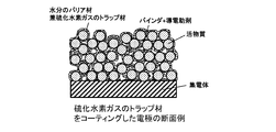
- the electrode for a non-aqueous electrolyte according to the present invention can trap the hydrogen sulfide gas generated from the inside of the electrode for some reason inside the electrode and suppress the outflow of the hydrogen sulfide gas to the outside of the electrode. Further, elution of lithium polysulfide generated inside the electrode into the electrolytic solution can be suppressed.
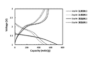
- FIG. 8 is a diagram showing a comparison of initial charge / discharge curves in Comparative Example 2 and Example 2.
- FIG. 6 is a diagram showing a comparison of initial charge / discharge curves in Comparative Example 3 and Example 3. It is the figure which compared and showed the initial charging / discharging curve in the comparative example 4 and the example 4.
- the coating material functions as a barrier material (protective film) against moisture entering from the outside, and prevents direct contact with the sulfur-based material contained in the active material layer.
- An example of the electrode for a lithium ion battery according to the electrode of the present invention is an electrode cross section as shown in FIG.
- the coating material may be present on at least the surface of the active material layer by applying the coating material to the active material layer of the electrode and drying. This coating material can suppress the elution of lithium polysulfide generated by the active material material into the electrolytic solution.
- the volume of the sulfur-based material for the active material layer does not change as much as Si and Sn, but it expands and contracts during charge and discharge, so the coating material must have some degree of binding property.
- the binding property between the coating material and the active material layer is weak, peeling or cracks are generated in the coating material due to the volume change of the active material.
- the exposed active material is brought into contact with the electrolytic solution, lithium polysulfide is eluted and the electric capacity of the electrode is reduced. Further, when the exposed active material is present, hydrogen sulfide gas is generated when moisture enters from the outside.
- the coating material is preferably an active material, or a silicate containing a siloxane bond capable of strongly adhering to the surface of the active material layer, or a silica fine particle aggregate containing a siloxane bond.
- the above-mentioned silicate or silica fine particle aggregate has a silanol group.
- the silicate having a silanol group contained in the coating material or the silica fine particle aggregate having a silanol group takes in the water that has entered the coating material, and the coating material is alkaline with a pH value of 9 or more. An aqueous solution is produced.
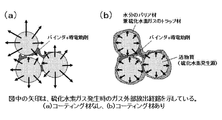
- the sulfide of an alkali metal is hydrolyzed when it comes into contact with water to generate hydrogen sulfide gas, but in the electrode of the present invention, the sulfur-based material temporarily contained in the active material layer is brought into contact with an alkaline aqueous solution, When the sulfide contained in the sulfur-based material reacts with the water content of the alkaline aqueous solution to generate hydrogen sulfide gas, the hydrogen sulfide gas is included in the coating material that covers the active material. Therefore, as shown in FIG. 2B, the hydrogen sulfide gas cannot be released to the outside of the electrode unless it passes through the coating material.
- the alkaline aqueous solution generated in the coating material is an excellent trap material for hydrogen sulfide gas, and the hydrogen sulfide gas is released to the outside of the electrode by being dissolved and neutralized in the alkaline aqueous solution. It has the effect of preventing
- the coating material suppresses the contact between the sulfur-based material and the water, and the sulfide contained in the sulfur-based material reacts with the water to generate. It has a structure that suppresses the release of hydrogen sulfide gas to the outside of the electrode.
- the silanol group is a functional group in which a hydroxy group (—OH) is bonded to silicon represented by the chemical formula —Si—OH.
- a material having a silanol group there are various silicon compounds such as silyl alcohol, silicone resin, and silanol-modified organic material.
- the coating material is a silicate containing a siloxane bond as a component, or silica fine particles. It is characterized by being an aggregate. The reason why the coating material contains a siloxane bond (Si—O—Si) as a component is that when the siloxane bond is hydrolyzed, it has an effect of producing a silanol group.
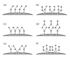
- silanol groups are present in various forms as shown in (a) to (f) of FIG.
- the silanol groups may be confined in the pores of the coating material.
- the pores contained in the silicate or silica fine particles can also be expected to have an effect such as physical adsorption of hydrogen sulfide gas by the pores.
- the pores are preferably 0.1 nm or more and 1000 nm or less, and more preferably 0.5 nm or more and 500 nm or less, based on their diameter or width.
- the siloxane bond contained in the coating material is hydrolyzed by the water inside the battery or the water supplied from outside the cell to form a silanol group. It is considered that this silanol group undergoes a dehydration reaction with hydrogen sulfide gas to form a chemical bond.
- Silicate heat treatment causes dehydration condensation reaction of silanol groups and cures while forming siloxane bonds.
- the siloxane structure changes to a silanol structure.
- the siloxane structure is less likely to change to a silanol structure as the temperature of the heat treatment increases, although it depends on the conditions for forming a siloxane bond. That is, the siloxane structure formed at low temperature relatively easily changes to the silanol structure when contacted with water.
- silica sol is an inorganic material containing a siloxane bond.
- Silica sol is a colloidal solution in which fine particles of silica (silicon oxide) are dispersed in water.
- the particle size of silica dispersed in the liquid is 1 nm or more and 500 nm or less, and hydroxyl groups and silanol groups are present on the surface thereof.
- the aggregate refers to an agglomerate formed by fine particles dispersed in a liquid.
- the silica fine particles obtained from the silica sol form a siloxane bond by a dehydration condensation reaction by heat treatment, and this siloxane bond is formed inside the oxide particles.
- the sol does not easily shrink continuously during drying, so the coating film that generated cracks adheres to the active material layer. Therefore, comparing silicate with silica sol, silicate is preferable, and the elution amount of lithium polysulfide into the electrolytic solution can be suppressed, and high capacity and long life of the battery can be achieved. Further, the aqueous solution in which the silicate is dissolved exhibits strong alkalinity (pH 10 or more), but since it does not react exceptionally with aluminum, it is possible to use aluminum for the current collector.
- silicate since silicate does not dissolve in organic solvents, it becomes a water-based (aqueous) coating material.
- the silica sol has an advantage that the nano-level silica sol can be dispersed in an organic solvent in addition to water.
- a colloidal solution in which fine silica particles are dispersed in an organic solvent is also called an organosilica sol, and is an alcohol, ketone, ether, aldehyde, amine, ester, lactone, terpene, thiol, toluene, xylene, N-methyl-2-pyrrolidone (NMP). ) And other various organic solvents. Therefore, it is possible to develop combinations such as a combination with a material that reacts by contact with water, or a combination with a resin that cannot be dissolved in water.
- the silicate containing a siloxane bond may be an alkali metal silicate, a guanidine compound silicate, or an ammonium compound silicate.
- silicates examples include orthosilicate (A 4 SiO 4 ), metasilicate (A 2 SiO 3 ), pyrosilicate (A 6 Si 2 O 7 ), and disilicate (A 2 Si 2 O 5 ), polysilicates such as tetrasilicate (A 2 Si 4 O 9 ), and many such as A 2 Si 2 O 5 , A 2 Si 3 O 7 , and A 2 Si 4 O 9 .
- A alkali metal element, or guanidine group, triethanolammonium group, tetramethanolammonium group).
- silicates tend to have a lower melting point as the proportion of A in the silicate increases and at the same time exhibit solubility in water.
- silicates are capable of continuously changing the proportion of A in the silicate, and any salt can be adjusted.
- the general molecular formula of silicate is A 2 O -Represented in the form of nSiO 2 .
- A is an alkali metal element (Li, Na, K, Rb, Cs) or at least one selected from a guanidine group, a triethanolammonium group, and a tetramethanolammonium group, and n is 0.5 or more and 5. It is 0 or less.
- a in the general formula is Li, Na, or K.
- the siloxane structure easily changes to a silanol structure.
- Li easily changes into a silanol structure, and since a coating material having high ion conductivity is obtained, the input / output characteristics of the battery are excellent.
- Na or K is excellent in the mechanical strength of the coating material, the binding property with the active material, and the wear resistance of the electrode.
- n in the general formula is 0.7 or more and 3.5 or less, and more preferably 0.8 or more and 3.0 or less. If the number n of SiO 2 exceeds 5.0, the hydrogen sulfide gas trapping property becomes low. Further, the binding property with the active material layer is poor, and peeling and cracking are likely to occur remarkably due to external factors such as a volume change of the electrode during charge / discharge and a nail piercing test.
- n is less than 0.5, the viscosity is so high that it becomes difficult for the coating material to permeate or apply to the electrode active material layer.
- A is a silicate that is an alkali element and a sulfur-based material is used as the active material
- this silicate when this silicate is applied to the active material layer, an alkali metal sulfate is formed between the active material and the coating material. Is generated.
- Hydrogen sulfide gas exhibits weak acidity when dissolved in water (H 2 S ⁇ HS ⁇ + H + ).
- hydrogen sulfide ions HS ⁇
- hydrogen sulfide gas tends to be generated as the pH shifts to an acidic region.
- a part of the Si site in the silicic acid compound is substituted with a transition metal element such as Al, Zr, Ti, Mg, Mo, Sr, Ca, Zn, Ba, B, W, Ta, Ce, Hf, and Y. Good.
- a transition metal element such as Al, Zr, Ti, Mg, Mo, Sr, Ca, Zn, Ba, B, W, Ta, Ce, Hf, and Y. Good.
- these structures can be roughly classified into crystalline and non-crystalline, but it is preferable that the siloxane structure is an amorphous one that easily changes to a silanol structure when contacted with water. Further, if it is amorphous, it does not crack in a specific direction like crystals, so that hydrogen sulfide gas can be trapped more effectively. In addition, since resistance to hydrofluoric acid is improved, it is possible to make it difficult for electrode collapse due to hydrofluoric acid to occur.
- Amorphous solids usually consist of disordered molecular arrangements and do not possess distinct crystal lattices. Also, the solubility of amorphous solids is higher than that of crystalline forms and does not have a constant melting point. Therefore, the absence of a clear peak in the powder X-ray diffraction (XRD) pattern and the absence of a melting endothermic peak in a differential thermal analysis (DTA) curve or a differential scanning calorimetry (DSC) curve indicate an amorphous form. Is shown.
- the amorphous silicate or silica fine particle aggregate does not have a sharp peak which is a characteristic of crystalline morphology in XRD, and the diffraction angle (15 ° to 40 ° within a range of Cu-K ⁇ rays ( 2 ⁇ ) shows a broad broad peak typical of the so-called halo pattern.
- an amorphous body can be obtained by heat-treating the electrode at a temperature rising rate of 10 ° C./h or more and at a temperature of 80 ° C. or more and 600 ° C. or less, though it depends on the environment and time of the heat treatment. it can.
- the amount of silanol groups in the silicate tends to decrease as the temperature of heat treatment increases.
- the silanol group becomes an essential component for reacting with hydrogen sulfide gas
- the amount of silanol group in the coating material is preferably 100 ppm or more, more preferably 200 ppm or more, and further preferably 300 ppm. .. Therefore, the upper limit of the temperature of the heat treatment is preferably 350 ° C or lower, more preferably 250 ° C or lower, and further preferably 180 ° C or lower.
- the amount of silanol groups can be quantified from the attribution of the spectrum obtained by the dipole decoupling / magic angle rotation method in Si-NMR measurement.
- the coating material preferably further contains a surfactant.
- a surfactant By including the surfactant in the coating material, the lyophilicity of the coating material to the active material layer is improved, and the coating material easily and uniformly penetrates into the active material layer. Therefore, a uniform coating material is formed in the active material layer, and the hydrogen sulfide gas trapping property is further improved.
- the sulfur-based material may exhibit water repellency.
- the content of the surfactant with respect to the coating agent may be 0.001% by mass or more and 5.0% by mass or less.
- the coating material may be difficult to permeate into the active material layer, and if it exceeds 5% by mass, foaming tends to occur on the surface of the active material layer and the electrode performance tends to vary. Addition of defoamer is required.
- nonionic surfactant nonionic surfactant, anionic surfactant, cationic surfactant, amphoteric surfactant, nonionic surfactant, etc. may be used.
- the coating material preferably further contains a metal salt of at least one transition metal element selected from Mn, Mg, Ca, Fe, Co, Ni, Cu, Zn, Al, Ba and Cu.
- the coating material containing the metal salt of these transition metal elements can trap hydrogen sulfide gas more effectively. More preferred are Mn, Fe, Co, Ni, Cu, Zn, and Al.
- an inorganic salt such as sulfuric acid, hydrochloric acid, nitric acid or phosphoric acid, or an organic salt such as formic acid, acetic acid or oxalic acid can be used.
- phosphate is preferable from the viewpoint of improving the water resistance of the coating material. When the water resistance of the coating material is low, the coating material may disappear when coming into contact with water, and the trap function may be deteriorated.
- the metal salt is preferably 1 mol% or more and 80 mol% or less, more preferably 10 mol or more and 70 mol% or less, when the total amount of the transition metal element and the silicon element in the silicate is 100 mol%. 20 mol% or more and 60 mol% or less is desirable.
- the transition metal element is less than 1 mol%, the effect of trapping hydrogen sulfide gas is not remarkably exhibited. As the amount of the transition metal element increases, the effect of trapping hydrogen sulfide gas tends to increase, but if it exceeds 80 mol%, the trapping ability decreases.
- A at least one kind of alkali metal element selected from Li, Na, K, Rb, and Cs.
- the content of A 2 CO 3 or AHCO 3 may be 1% by mass or more and 50% by mass or less with respect to the coating material.
- the coating material may be a silicate in which A 2 CO 3 or AHCO 3 powder is mixed, but since the water resistance of the coating material is greatly improved, the silicate absorbs a carbonic acid source and It is preferable to produce 2 CO 3 , or AHCO 3 . When the water resistance of the coating material is low, the coating material may disappear when coming into contact with water, and the trap function may be deteriorated.
- the carbonic acid source may be any material that reacts with silicic acid to generate A 2 CO 3 or AHCO 3 .
- carbon dioxide gas carbon dioxide gas
- liquefied carbon dioxide liquefied carbon dioxide gas
- dry ice solid carbon dioxide
- carbon oxides such as carbon monoxide
- carbonate compounds such as calcium carbonate and magnesium carbonate
- sodium hydrogen carbonate carbonic acid
- hydrogen carbonate such as calcium hydrogen.
- carbon dioxide gas is preferred.
- the electrode coated with the coating material may be left in a carbon dioxide gas atmosphere.
- the carbon dioxide gas atmosphere is preferably 0.12 MPa or more.
- liquefied carbon dioxide liquefied carbon dioxide
- dry ice solid carbon dioxide
- you may bake in the state.
- the coating material may contain carbon.
- carbon By including carbon in the coating material, electronic conductivity can be imparted to the coating material.
- the amount of carbon contained in the coating material may be 0.1% by mass or more and 70% by mass or less, when the total amount of the coating material and carbon is 100% by mass.
- the carbon the same material as the conductive auxiliary agent described later can be used.
- the active material As a method of improving the electronic conductivity of the active material, there is a method of supporting carbon on the surface of the active material by heat-treating the carbon precursor hydrocarbon gas and the like together with the active material.
- the active material is a sulfur-based material
- the sulfur-based material (sulfur-modified polyacrylonitrile) described in Non-Patent Document 1 has excellent heat resistance
- the hydrocarbon gas acts as a reducing agent
- the sulfur content in the active material becomes hydrogen sulfide gas and the sulfur content in the active material decreases.
- the electrode according to the present invention is an electrode for a non-aqueous electrolyte battery, but the non-aqueous electrolyte battery is a non-aqueous electrolyte battery that does not contain water as a main component, and other than a lithium ion battery, a sodium ion battery or a potassium ion battery. Batteries, magnesium ion batteries, calcium ion batteries and the like are included.
- the lithium-ion battery is a non-aqueous electrolyte battery that does not contain water as a main component, and also means a battery in which lithium ions are included in the ions responsible for electrical conduction.
- a lithium ion battery for example, a lithium ion battery, a metal lithium battery, a lithium polymer battery, an all-solid-state lithium battery, an air lithium ion battery, or the like is applicable, and may be a primary battery or a secondary battery (storage battery). The same applies to other non-aqueous electrolyte batteries.
- the electrodes used in these batteries include a positive electrode and a negative electrode, but when a sulfur-based material is used as the active material of the electrodes, the charging / discharging voltage is 1 V or more and 3 V or less (vs. Li / Li + ).
- the sulfur-based material can be used as an active material for both the positive electrode and the negative electrode. Examples of the sulfur-based material include elemental sulfur, carbon sulfide, polysulfide, carbon polysulfide, sulfur-modified polyacrylonitrile, disulfide compound, sulfur-modified rubber, sulfur-modified pitch, sulfur-modified anthracene, sulfur-modified ethylene glycol, and metal sulfide. Be done.
- These sulfur-based materials are solid materials that decompose when contacted with water when lithiated to generate hydrogen sulfide gas.
- the elemental sulfur is not particularly limited, but ⁇ -type sulfur, ⁇ -type sulfur, and ⁇ -type sulfur having an S 8 structure can be used.
- Sulfur-based materials have a higher sulfur content than elemental sulfur and metal sulfides from the results of elemental analysis (ICP), from the viewpoint that lithium polysulfide is difficult to elute into the electrolytic solution and the material has excellent electronic conductivity.
- ICP elemental analysis
- Is preferably 10% by mass or more and 90% by mass or less
- carbon is 10% by mass or more and 90% by mass or less
- hydrogen is 0% by mass or more and 10% by mass or less.
- Examples thereof include carbon sulfide, polysulfide, carbon polysulfide, sulfur-modified polyacrylonitrile, disulfide compound, sulfur-modified rubber, sulfur-modified pitch, and sulfur-modified anthracene.
- the sulfur content is 10 mass% or more and 80 mass% or less
- carbon is 20 mass% or more and 90 mass% or less
- hydrogen is It is a sulfur-modified polyacrylonitrile having a content of 0% by mass or more and 10% by mass or less and a nitrogen content of 5% by mass or more and 30% by mass or less.
- the sulfur-based material preferably has a median diameter (D 50 ) of 0.1 ⁇ m or more and 20 ⁇ m or less.
- the median diameter is a volume-based diameter, and the diameter of secondary particles is measured by the laser diffraction scattering method.
- the median diameter of the sulfur-based material is more preferably 1 ⁇ m or more and 20 ⁇ m or less, still more preferably 1 ⁇ m or more and 15 ⁇ m or less.
- the above-mentioned sulfur-based materials may be used alone or in combination of two or more, or may be used as a mixture with a positive electrode active material or a negative electrode active material described later.
- the shape of the sulfur-based material when used as an active material is not particularly limited, and may be spherical, elliptical, facet-shaped, fiber-shaped, flake-shaped, donut-shaped, or hollow. Further, the sulfur-based material may include a compound that decomposes into a solid electrolyte in the process of initial charge or discharge, or a compound that can store and release alkali metal ions.
- the solid electrolyte is not particularly limited as long as it is a substance having ion conductivity, but is preferably a solid electrolyte represented by Li ⁇ X ⁇ Y ⁇ . In the formula, 0 ⁇ ⁇ 4, 0 ⁇ ⁇ ⁇ 2, and 0 ⁇ ⁇ ⁇ 5.
- the solid electrolyte also serves as a buffer material that is a material that can reversibly store and release lithium ions.
- X is, for example, one or more of Si, Ti, Mg, Ca, Al, V, Ge, Zr, Mo, and Ni
- Y is O, S, F, Cl, Br, I, P, B. It is any one or more of 2 O 3 , C 2 O 4 , CO 3 , PO 4 , S, CF 3 SO 3 , and SO 3 .
- Examples of the compound that decomposes into the solid electrolyte and the compound that can store and release the alkali metal ion include SiO, GeO, GeS, GeS 2 , SnO, SnO 2 , SnC 2 O 4 , SnO-P 2 O. 5 , SnO—B 2 O 3 , SnS, SnS 2 , Sb 2 S 3 , SnF 2 , SnCl 2 , SnI 2 , SnI 4, and the like, and two or more of them may be used.
- an active material powder with a small particle size When an active material powder with a small particle size is used, particle disintegration may be reduced, the life characteristics of the electrode may be improved, or the specific surface area may increase, resulting in improved output characteristics.
- the particle size of the active material is small. Then, it is described that the initial discharge capacity is increased and the cycle life is also improved, and it can be seen that the particle size of the active material is correlated with the initial charge / discharge efficiency and the cycle life in the secondary battery.
- any one or more binders for granulation of polyimide, polybenzimidazole, styrene-butadiene rubber, polyvinylidene fluoride, carboxymethyl cellulose, and polyacrylic acid, and nano-sized active material particles As a negative electrode for a non-aqueous electrolyte secondary battery, an active material layer having silicon is provided on a current collector.
- Sulfur-based materials do not have the same large volume change as silicon, but when the particle size of the sulfur-based material as the active material is reduced to nano size, the contact area with the electrolyte solution increases and lithium polysulfide easily elutes. As a result, the electric capacity may decrease and the cycle characteristics may deteriorate.
- the coating material covers the particles of the active material. Therefore, the elution of lithium polysulfide can be suppressed.
- the primary particles of the active material preferably have a median diameter (D 50 ) of 0.01 ⁇ m or more and 20 ⁇ m or less, and the active material particles (secondary particles) after granulation have a median diameter (D 50). ) It is preferably in the range of 0.5 ⁇ m or more and 100 ⁇ m or less.
- the surface of the sulfur-based material as the active material can be partially or entirely coated with the coating material, and the elution of lithium polysulfide can be suppressed.
- a known granulation method can be applied, for example, fluidized bed granulation method, stirring granulation method, tumbling granulation method, spray drying method, extrusion granulation method, rolling granulation method.
- the dynamic granulation method and the coating granulation method are mentioned.
- the spray drying method and the fluidized bed granulation method are particularly preferable because they can be coated relatively uniformly.
- a suspension in which an active material is dispersed in a coating material is placed in a greenhouse heated to 50 ° C. or higher and 300 ° C. or lower from above, at 1 mL / min or more and 30 mL / min or less, and an air pressure of 0.
- agglomerated particles are formed and dried to obtain a granulated product.
- a powdered active material is put into a fluidized bed granulator, and hot air heated to 50 to 300 ° C. is blown from below to feed the powdered active material (granulate precursor Body) is mixed by fluidizing, and water in which the coating material is dissolved is sprayed onto the granule precursor from above with a nozzle, and the coating material is uniformly applied to the powder surface at 1 mL / min or more, 30 mL / min or less, and no air pressure.
- agglomerated particles are formed and dried to obtain a granulated product.
- the current collector Before the sulfur-based material becomes lithiated, it shows strong acidity when it comes into contact with water.Therefore, there is a problem that the current collector is oxidized when the water-based binder is used.
- the current collector to be described later should have a carbon layer. Is preferred.
- the acid in the sulfur-based material is neutralized.
- a coating material containing a silicate bond having a siloxane bond or a silica fine particle aggregate having a siloxane bond the acid in the sulfur-based material is neutralized.
- sulfate can be generated, and damage to the current collector that occurs when the aqueous binder is used can be reduced.
- the high temperature durability of the electrode may be improved.
- an aqueous solution in which silicate is dissolved exhibits strong alkalinity (pH 10 or higher), but it does not react exceptionally with aluminum. Therefore, when the current collector is aluminum, the current collector is less damaged by the alkali metal silicate.
- the active material layer contains a sulfur-based material as an active material and a resin-based binder.
- the resin-based binder is usually used, for example, polyvinylidene fluoride (PVdF), polytetrafluoroethylene (PTFE), polyimide (PI), polyamide, polyamideimide, aramid, polyacryl, styrene butadiene rubber (SBR).
- EVA Ethylene-vinyl acetate copolymer
- SEBS styrene-ethylene-butylene-styrene copolymer
- CMC carboxymethyl cellulose
- CMC-Na sodium carboxymethyl cellulose
- PVA Ethylene vinyl alcohol
- PVB Ethylene vinyl alcohol
- PE polyethylene
- PP polypropylene
- polyacrylic acid lithium polyacrylate, sodium polyacrylate, potassium polyacrylate, ammonium polyacrylate
- EVA Ethylene-vinyl acetate copolymer
- SEBS carboxymethyl
- a resin binder and an inorganic binder may be mixed and used.
- the inorganic binder may be, for example, a silicate type or a cement type, as well as a silicate type or a phosphate type as described in Patent Documents (Patent 6149147, JP-A-2018063912).
- the inorganic binder is lithium silicate, sodium silicate, potassium silicate, guanidine silicate, Inorganic materials such as ammonium silicate, fluorosilicate, aluminosilicate, aluminum phosphate, magnesium phosphate and calcium phosphate are preferable.
- the electrode of the present invention preferably contains no inorganic binder.
- the resin binder is preferably an aqueous (aqueous) binder.
- the aqueous binder, the dispersion of the binder component, or represents a binder in which the solvent used to dissolve is water, for example, styrene butadiene rubber, carboxymethyl cellulose, sodium carboxymethyl cellulose, polyacrylic acid, polyimide, polyacrylonitrile and the like. Be done.
- An electrode that uses a water-based binder makes it difficult for the water-based binder to absorb the electrolyte solvent and swell when the battery is operated in a high-temperature environment, and a battery with excellent high-temperature durability can be obtained.
- the content of the resin binder in the electrode of the present invention is 0.1% by mass or more and 60% by mass or less when the total amount of the active material, the resin binder and the conductive additive is 100% by mass. Is preferred, and more preferably 0.5% by mass or more and 30% by mass or less.
- the resin-based binder is less than 0.1% by mass, the mechanical strength of the electrode is low, so the active material is likely to fall off when the coating material is applied, and the cycle life characteristics of the battery may deteriorate. On the other hand, if it exceeds 60% by mass, the ionic conductivity and the electronic conductivity will be low, and since the ratio of the active material as an electrode is small, the electrode capacity density will be low.
- a conductive auxiliary agent can be contained in the active material layer, if necessary.
- the conductive additive is not particularly limited as long as it has electronic conductivity, and examples thereof include metals, carbon materials, conductive polymers, and conductive glasses, but in view of high electron conductivity and oxidation resistance. Therefore, carbon is preferable.
- the conductive additive is contained in an amount of 0 to 30% by mass, when the total amount of the active material, the resin binder and the conductive additive is 100% by mass. That is, the conductive additive is contained as needed. If it exceeds 30% by mass, the proportion of the active material as a battery is small, and the electrode capacity density tends to be low.
- the current collector is not particularly limited as long as it is a material that has electronic conductivity and can conduct electricity to the held sulfur-based material as an active material.
- a material that is unlikely to alloy with lithium is preferable.
- a material that is not easily oxidized is preferable.
- conductive substances such as C, Ti, Cr, Ni, Cu, Mo, Ru, Rh, Ta, W, Os, Ir, Pt, Al and Au, and these conductive substances.
- An alloy containing two or more of the above eg, stainless steel, Ni—Fe alloy
- conductive substances such as C, Ti, Cr, Ni, Cu, Mo, Ru, Rh, Ta, W, Os, Ir, Pt, Au and Al, and these conductive substances.
- Alloys containing two or more of the above eg, stainless steel, Al—Fe alloy
- a multi-layer structure of different metals such as iron coated with Al and Al coated with C may be used. From the viewpoint of material cost of the current collector and lightening of the battery, Al or an alloy using Al is preferable.
- Examples of the shape of the current collector include a linear shape, a rod shape, a plate shape, a foil shape, and a porous shape.
- the porous shape can increase the packing density, and the coating material easily penetrates into the active material layer. Therefore, it is preferable.
- Examples of the porous material include a mesh, a woven cloth, a non-woven cloth, an embossed body, a punched body, an expanded body, and a foamed body. In particular, the embossed body or the foamed body is preferable because of good output characteristics.
- the porosity of the porous current collector is not particularly limited, but may be 1% or more and 95% or less.
- An electrode of the present invention comprises the above current collector, an active material layer containing a sulfur-based material and a resin-based binder, and a coating material containing a silica fine particle aggregate containing a silicate bond containing a siloxane bond or a siloxane bond.
- the electrode of the present invention can be manufactured by forming an active material layer on the current collector and then applying a coating material to the active material layer.
- the coating material contains a silicate having a silanol group or a silica fine particle aggregate having a silanol group, and the coating material may be present in the active material layer. ..
- the coating material penetrates into the active material layer, so that the specific area of the coating material that traps hydrogen sulfide gas in the active material layer increases. Thereby, hydrogen sulfide gas generated from the active material can be efficiently trapped.
- the coating material is present in the active material layer, and further, a gap is present between the active material particles in the active material layer.
- the coating material penetrates into the active material layer, while the gaps between the active material particles in the active material layer are not completely filled with the coating material, leaving gaps between the active material particles.
- the coating amount of the coating material on the electrode varies depending on the capacity per unit of the electrode. For example, when the coating material of the electrode is applied on one side, the capacity per unit area of the electrode coated on one side is 3 mAh / In the case of cm 2 , the coating amount of the coating material on the electrode is preferably 0.01 mg / cm 2 or more and 3 mg / cm 2 or less, and more preferably the coating material per unit area of the electrode coated on one side. There, 0.02 mg / cm 2 or more and 0.5 mg / cm 2 or less.
- the preferable coating amount of the coating material to the electrode is 0.02 mg / cm 2. It is 2 or more and 6 mg / cm 2 or less, and more preferably 0.05 mg / cm 2 or more and 0.3 mg / cm 2 or less.
- the content of the coating material varies depending on the capacity per unit area of the electrode when the total solid content of the active material, the resinous binder, the conductive additive and the coating material is 100% by mass.
- the content of the coating material is preferably 0.1% by mass or more and 30% by mass or less, more preferably 0% by mass or less. 0.2 mass% or more and 20 mass% or less, and more preferably 0.5 mass% or more and 10 mass% or less.
- the active material layer before applying the coating material is preferably a porous body having voids with a porosity of 20% or more and 80% or less.
- the electrode has excellent electron conductivity, but when the porosity is less than 20%, it is difficult for the electrode to permeate when the coating material is applied and the electrode has a moisture content. It becomes difficult to trap hydrogen sulfide efficiently when it comes into contact with. Further, the coating material is likely to be deposited on the active material, which may reduce the ionic conductivity.
- it exceeds 80% not only the volume energy density of the electrode is lowered, but also the electron conductivity of the active material layer is deteriorated, and the battery tends to lack output characteristics.
- the electrode of the present invention by coating the active material layer having voids with a coating material, an electrode in which the surfaces of the voids are coated with the coating material can be manufactured.
- the void includes all of an independent space that is shielded from the outer surface, a space that has one path connected to the outer surface (so-called recess), and a space that has a plurality of paths connected to the outer surface (so-called through hole). It is a concept.
- the outer surface is the outermost surface of the active material layer, that is, the surface that comes into contact with the roll portion when the pressure of the electrode is adjusted by a roll press.
- the porosity of the active material layer can be calculated based on the following formula using the apparent density d (g / cm 3 ) and the true density ⁇ (g / cm 3 ) of the active material layer.
- the apparent density d of the active material layer is a value obtained by dividing the mass (g) of the active material layer by the volume (cm 3 ) of the entire porous body including pores
- the true density ⁇ is Represents the value obtained by dividing the mass (g) of the active material layer by the volume (cm 3 ) of the porous body excluding pores.
- Porosity of active material layer (%) (1-d / ⁇ ) ⁇ 100
- the active material layer is a porous body having voids with a porosity of 5% or more and 70% or less from the viewpoint of efficiently trapping hydrogen sulfide gas without deteriorating the electrode characteristics. Is more preferable, 20% or more and 65% or less is more preferable, and 25% or more and 60% or less is further preferable.
- the thickness of the coating material existing on the surface of the voids is preferably 10 nm or more and 5000 nm or less.
- it is less than 10 nm, it becomes difficult to trap hydrogen sulfide efficiently when the electrode comes into contact with water. Further, when lithium polysulfide is generated, it is eluted into the solvent of the electrolytic solution to reduce the electric capacity.
- it exceeds 5000 nm not only the weight energy density of the electrode is lowered, but also the ionic conductivity of the active material layer is poor, and the battery tends to lack output characteristics. From such a viewpoint, it is more preferably 50 nm or more and 1000 nm or less.
- the apparent thickness of the electrode is increased by 5000 nm at the maximum, and if it is within the preferable range, it is increased by 1000 nm or less at the maximum. Yes, it does not significantly reduce the volumetric energy density of the battery.
- the coating material is mainly made of inorganic material and is very thin, it is highly possible that an electrode with excellent heat dissipation can be obtained by suppressing the decrease in thermal conductivity of the electrode.
- the battery of the present invention has a battery structure in which the electrode of the present invention is used as a positive electrode or a negative electrode, the positive electrode and the negative electrode are joined via a separator, and the electrode is sealed in a state of being immersed in an electrolytic solution.
- the structure of the battery is not limited to this, and the present invention can be applied to existing battery forms and structures such as a laminated battery and a wound battery.
- the negative electrode is not particularly limited as long as it is the negative electrode used in the non-aqueous electrolyte secondary battery. That is, the active material used for the negative electrode is a material capable of reversibly occluding and releasing one or more ions selected from the group of lithium ions, sodium ions, potassium ions, magnesium ions and calcium ions, or lithium. The material is not particularly limited as long as it can be alloyed with.
- Li, C, Mg, Al, Si, P, Ca, Sc, Ti, V, Cr, Mn, Fe, Co, Ni, Cu, Zn, Ga, Ge, Y, Zr, Nb, Mo, Pd It has at least one element selected from the group consisting of Ag, Cd, In, Sn, Sb, W, Pb, S and Bi, and is selected from the group of Li, Na, K, Mg and Ca.
- An alloy, a compound, an oxide, a chalcogenide or a halide using any of these elements may be used.
- the elements are preferably Li, Na, K, Mg, Ca, Al, Si, Zn, Ge, Ag, Sn, S, and the like, and the alloy is Si—Al, Al—Zn. , Al-Li, Mg-Li, Si-Mg, Si-La, Al-Ge, Si-Ge, Si-Ag, Si-Sn, Si-Ti, Si-Y, Si-Cr, Si-Ni, Si -Zr, Si-V, Si-Nb, Si-Mo, Zn-Sn, Ge-Ag, Ge-Sn, Ge-Sb, Ag-Sn, Ag-Ge, Sn-Sb, S-Sn, S-Sb Etc.
- the alloy may be a solid solution alloy, a eutectic alloy, a hypoeutectic alloy, a hypereutectic alloy, or a peritectic alloy.
- the surface of the active material particles may be coated with a material having excellent electron conductivity or ceramics. Two or more materials that can reversibly occlude and release one or more ions selected from the group of lithium ion, sodium ion, potassium ion, magnesium ion and calcium ion derived from these alloys are used. You may.
- the negative electrode active material has a large irreversible capacity, the battery capacity will be extremely reduced, so it is preferable to perform pre-doping treatment in advance before assembling the battery.
- the positive electrode is not particularly limited as long as it is a positive electrode used in a non-aqueous electrolyte secondary battery. That is, known electrodes including an alkali metal transition metal oxide system, a vanadium system, a solid solution system (excess system of an element selected from the group of lithium, sodium, potassium, magnesium and calcium), a carbon system, an organic system, etc. Used.
- alkali metal transition metal oxide system examples include LiCoO 2 , Li 0.9 Na 0.1 CoO 2 , LiNiO 2 , LiNi 0.5 Co 0.5 O 2 , LiNi 0.33 Mn 0.33 Co 0. .33 O 2 , LiNi 0.5 Mn 0.2 Co 0.3 O 2 , LiNi 0.6 Mn 0.2 Co 0.2 O 2 , LiNi 0.8 Mn 0.1 Co 0.1 O 2 , Li (Ni, Co, Al) O 2 , LiMnO 2 , LiMn 2 O 4 , LiFePO 4 , LiFe 0.5 Mn 0.5 PO 4 , LiMnPO 4 , Li 2 MnSiO 4 , Li 2 FeSiO 4 , Li 2 (Mn).
- vanadium-based material examples include LiV 2 O 5 , LiVO 2 , Li 3 VO 4 , Li 3 V 2 (PO 4 ) 3 and the like.
- the solid solution system for example, Li 2 MnO 3 -LiNiO 2, Li 2 MnO 3 -LiMnO 2, Li 2 MnO 3 -LiCoO 2, Li 2 MnO 3 -Li (Ni, Mn) O 2, Li 2 MnO 3 - Examples thereof include Li (Ni, Co) O 2 , Li 2 MnO 3 —Li (Mn, Co) O 2 , and Li 2 MnO 3 —Li (Ni, Mn, Co) O 2 .
- Carbon types include graphite, soft carbon, hard carbon, and glassy carbon.
- Organic systems include rubeanic acid, tetracyanoquinodimethane, triquinoxalinylene, phenazine dioxide, trioxotriangulene, indigo carmine, nitronyl nitroxide radical compounds, radialene compounds, aliphatic cyclic nitroxyl radicals, Examples thereof include benzoquinones.
- the alkali metal transition metal oxide-based, vanadium-based, solid solution-based (lithium-rich), carbon-based, and organic-based positive electrode active materials may be materials in which all or part of oxygen sites are replaced by fluorine. Alternatively, a material in which a part of the lithium site is replaced with another alkali metal element may be used.
- the above positive electrode active materials may be used alone or in combination of two or more.
- the positive electrode active material When a sulfur-based material is used as the positive electrode active material, or when neither the positive electrode nor the negative electrode contains a lithium compound as the active material, the battery capacity is extremely reduced or does not operate. Therefore, it is preferable to perform lithium doping treatment on one or both electrodes. ..
- Patent Document 10 As the lithium doping method, as described in Patent Document 10 and Non-Patent Document 4, known methods such as an electrochemical method, an alkali metal sticking method, and a mechanical method can be used.
- the electrolyte used in the battery of the present invention can transfer one or more ions selected from the group of lithium ion, sodium ion, potassium ion, magnesium ion and calcium ion from the positive electrode to the negative electrode or from the negative electrode to the positive electrode. It may be a liquid or a solid, and one that can move lithium ions is particularly preferable, and the same electrolyte as that used for a known lithium ion battery can be used. Examples thereof include an electrolytic solution, a gel electrolyte, a solid electrolyte, an ionic liquid, and a molten salt.
- the electrolytic solution means a state in which an electrolyte is dissolved in a solvent.
- the electrolytic solution needs to contain one or more ions selected from the group of lithium ions, sodium ions, potassium ions, magnesium ions and calcium ions, it is particularly limited as long as it is used in these ion batteries. It is not composed of electrolyte salt and electrolyte solvent.
- the electrolyte salt since it is necessary to contain one or more ions selected from the group of lithium ion, sodium ion, potassium ion, magnesium ion and calcium ion, the electrolyte salt is used in these ion batteries. There is no particular limitation as long as it can be used, but a lithium salt is preferable. Examples of the lithium salt include lithium hexafluorophosphate (LiPF 6 ), lithium perchlorate (LiClO 4 ), lithium tetrafluoroborate (LiBF 4 ), lithium trifluoromethanesulfonate (LiCF 3 SO 4 ), lithium bistrifluoro.
- LiPF 6 lithium hexafluorophosphate
- LiClO 4 lithium perchlorate
- LiBF 4 lithium tetrafluoroborate
- LiCF 3 SO 4 lithium trifluoromethanesulfonate
- LiN (SO 2 CF 3 ) 2 methanesulfonylimide (LiN (SO 2 CF 3 ) 2 ), lithium bispentafluoroethanesulfonylimide (LiN (SO 2 C 2 F 5 ) 2 ), lithium bisoxalate borate (LiBC 4 O 8 ), and the like. At least one selected from the above can be used.
- LiPF 6 is particularly preferable because it has a high electronegativity and is easily ionized.
- An electrolytic solution containing LiPF 6 has excellent charge / discharge cycle characteristics and can improve the charge / discharge capacity of the secondary battery.
- the concentration of the electrolyte salt in the electrolytic solution is preferably in the range of 0.5 mol / L to 2.5 mol / L, more preferably in the range of 0.8 mol / L to 2.0 mol / L.
- the solvent for the electrolyte is not particularly limited as long as it can be used in one or more ion batteries selected from the group consisting of lithium ion, sodium ion, potassium ion, magnesium ion and calcium ion.
- ion batteries selected from the group consisting of lithium ion, sodium ion, potassium ion, magnesium ion and calcium ion.
- PC propylene carbonate
- DMC dimethyl carbonate
- DEC diethyl carbonate
- EMC ethylmethyl carbonate
- GBL ⁇ -butyrolactone
- ⁇ -valerolactone methyl formate (MF)
- 2 -Methyltetrahydrofuran 1,3-dioxolane, 4-methyl-1,3-dioxolane, dimethoxyethane (DME), 1,2-diethoxyethane, diethyl ether, sulfolane, tetrahydrofuran (TH
- a mixture of the cyclic carbonate such as EC or PC and the chain carbonate such as DMC, DEC or EMC is preferable.
- the mixing ratio of the cyclic carbonate and the chain carbonate can be arbitrarily adjusted within the range of 10% by volume to 90% by volume for both the cyclic carbonate and the chain carbonate.
- the solvent of the electrolyte containing VC or VEC, FEC, ES it is preferable to use the solvent of the electrolyte containing VC or VEC, FEC, ES.
- the content of VC, VEC, FEC, or ES is preferably 0.1 to 20% by mass, more preferably 0.1% by mass when the electrolytic solution (total amount of electrolyte and solvent) is 100% by mass. It is 2% by mass to 10% by mass.
- the concentration of this lithium salt in the electrolytic solution is preferably 0.5 to 2.5 mol / L, and more preferably 0.8 to 2.0 mol / L.
- Ionic liquids and molten salts are classified into pyridine type, alicyclic amine type, aliphatic amine type, etc. according to the type of cation (cation).
- a variety of ionic liquids or molten salts can be synthesized by selecting the type of anion (anion) to be combined with this.
- ammonium-based ions such as imidazolium salts and pyridinium salts, phosphonium-based ions, and inorganic ions are used.
- anions used include halogen-based substances such as bromide ion and triflate, boron-based substances such as tetraphenylborate, and hexafluoro.
- Phosphorus such as phosphate is available.
- Ionic liquids and molten salts include, for example, cations such as imidazolium, Br ⁇ , Cl ⁇ , BF 4 ⁇ , PF 6 ⁇ , (CF 3 SO 2 ) 2 N ⁇ , CF 3 SO 3 ⁇ , FeCl 4 ⁇ . It can be obtained by a known synthesis method in which it is combined with an anion such as. If it is an ionic liquid or a molten salt, it can function as an electrolytic solution without adding an electrolyte.
- An assembled battery according to one aspect of the present invention is characterized by including the battery of the present invention.
- An electric device is characterized by including the battery or the assembled battery of the present invention.
- Examples of the electric device include an iron, a whisk, an integrated computer, a clothes dryer, a medical device, an earphone, an intercom, a wearable terminal, a video device, an air conditioner, an air circulator, a gardening machine, a motorcycle, an oven, a music player, and the like.
- Music recorder hot air heater, toys, car components, flashlight, loudspeaker, car navigation system, cassette stove, household storage battery, nursing machine, humidifier, dryer, oil dispenser, water dispenser, suction machine, safe box, glue gun, mobile phone Telephones, portable information devices, air purifiers, air-conditioning clothes, game machines, fluorescent lights, pill removal machines, cordless phones, coffee makers, coffee warmers, ice shaving machines, kotatsu, copy machines, haircutting devices, shavers, lawn mowers, Automobiles, lighting equipment, dehumidifiers, sealers, shredders, automatic external defibrillators, rice cookers, stereos, stoves, speakers, trouser presses, smartphones, rice mills, washing machines, toilet seats with cleaning functions, sensors, fans, submarines , Blower, vacuum cleaner, flying car, tablet, body fat meter, fishing tackle, digital camera, TV, TV receiver, video game, display, disc changer, desktop computer, train, TV, electric carpet, desk lamp, Electric stoves, electric kettles, electric blankets, calculators,
- the method for producing a non-aqueous electrolyte battery of the present invention is the above-mentioned current collector as an electrode, an active material layer containing a sulfur-based material and a resin binder, and a silica fine particle aggregate containing a silicate bond or a siloxane bond.
- a coating material containing a coating material containing and is characterized by including a step of forming an active material layer on a current collector and further applying a coating material to the active material layer.
- sodium silicate is described as an example of the coating material, but the present invention is not limited to this.
- sulfur-modified polyacrylonitrile will be described as an example of the sulfur-based material, the sulfur-based material is not limited to this.
- a lithium ion battery will be described as an example of the battery, but the battery is not limited to this.
- Sulfur-modified polyacrylonitrile-1 is a mixed powder in which polyacrylonitrile and elemental sulfur are adjusted to have a mass ratio of 1: 5, and the mixture is calcined in a nitrogen gas atmosphere at 400 ° C. for 1 hour, and after desulfurization under reduced pressure, Obtained by classifying.
- the median diameter (D 50 ) of the obtained sulfur-modified polyacrylonitrile (1) is 9 ⁇ m.
- Sulfur-modified polyacrylonitrile-2 was obtained by pulverizing sulfur-modified polyacrylonitrile-1 in an automatic mortar (manufactured by Nissou Kagaku Co., Ltd .: ANM1000) for 1 hour in the air.
- the median diameter (D 50 ) of the obtained sulfur-modified polyacrylonitrile-2 is 8 ⁇ m.
- Sulfur-modified polyacrylonitrile-3 was placed in a container made of zirconia and sealed with sulfur-modified polyacrylonitrile-1 and zirconia balls having a diameter of 4 mm under an argon gas environment, and then rotated using a planetary ball mill (Pulverisette 7 manufactured by Fritsch Ltd.). It was obtained by performing mechanical milling treatment under each condition of several 360 rpm (gravitational acceleration about 10 G) for 1 hour. The median diameter (D 50 ) of the obtained sulfur-modified polyacrylonitrile-3 is 3 ⁇ m.
- Sulfur-modified polyacrylonitrile-4 uses a high-speed planetary ball mill (Kurimoto Teiji Co., Ltd., Kurimoto Eat) after sealing the sulfur-modified polyacrylonitrile-1 and zirconia balls with a diameter of 4 mm in a zirconia container in an argon gas environment and sealing.
- the input frequency was 33.7 Hz (gravitational acceleration: about 50 G), and mechanical milling was performed under each condition for 1 hour.
- the median diameter (D 50 ) of the obtained sulfur-modified polyacrylonitrile-4 is 3 ⁇ m.
- Comparative Example 1 ⁇ Preparation of sulfur-modified polyacrylonitrile positive electrode> (Comparative Example 1)
- a slurry of sulfur-modified polyacrylonitrile-1, styrene-butadiene rubber (SBR), sodium carboxymethyl cellulose (CMC-Na), and carbon black was used to prepare a carbon-coated aluminum foil (thickness) using a doctor blade. 20 ⁇ m), dried in air at 80 ° C., and then heat-treated under vacuum at 150 ° C. for 10 hours.
- the capacity density per one surface of the electrode was 2 mAh / cm 2, and the porosity of the electrode was 57%.
- Comparative example 2 The electrode of Comparative Example 2 was prepared by applying a slurry containing sulfur-modified polyacrylonitrile-2, an acrylic binder, and carbon black to a carbon-coated aluminum foil (thickness 20 ⁇ m) using a doctor blade, and then at 80 ° C. in the atmosphere. After drying, it was then heat-treated under the conditions of vacuum 140 ° C. for 10 hours. The capacity density per one surface of the electrode was 2.1 mAh / cm 2, and the porosity of the electrode was 56%.
- Comparative Example 3 The electrode of Comparative Example 3 is the same as that of Comparative Example 2 except that sulfur-modified polyacrylonitrile-3 is used.
- Comparative Example 4 The electrode of Comparative Example 4 is the same as that of Comparative Example 2 except that sulfur-modified polyacrylonitrile-4 is used.
- Example 1 For the electrode of Example 1, the same slurry as in Comparative Example 1 was applied to a carbon-coated aluminum foil (thickness 20 ⁇ m) with a doctor blade and then dried at 80 ° C. in the atmosphere, and then sodium silicate was applied to the active material layer of the electrode. An aqueous solution was applied by a spray gun, dried at 80 ° C. in the atmosphere, and then heat-treated under the conditions of vacuum 150 ° C. for 10 hours to prepare the film. The applied amount (solid content) of sodium silicate per unit area was 0.2 mg / cm 2 . The electrode thickness of Example 1 was increased by about 300 nm as compared with Comparative Example 1.
- the sodium silicate aqueous solution is prepared by adding water to a silicate of the general formula Na 2 O ⁇ 3SiO 2 so that the solid content is 15% by mass, and the nonionic surfactant (octylphenol ethoxylate) is added to the whole solution.
- the nonionic surfactant octylphenol ethoxylate
- the capacity density per one surface of the electrode was set to 2 mAh / cm 2 .
- Example 2 For the electrode of Example 2, the same slurry as in Comparative Example 2 was applied to a carbon-coated aluminum foil (thickness 20 ⁇ m) with a doctor blade and dried at 80 ° C. in the air, and then sodium silicate was applied to the active material layer of the electrode. An aqueous solution was applied by a spray gun, dried at 80 ° C. in the atmosphere, and then heat-treated under the conditions of 140 ° C. in vacuum for 10 hours to prepare the film.
- Example 2 The electrode thickness of Example 2 was increased by about 400 nm as compared with Comparative Example 2.
- the applied amount (solid content) of sodium silicate per unit area was 0.2 mg / cm 2 .
- the sodium silicate aqueous solution is prepared by adding water to a silicate of the general formula Na 2 O ⁇ 2.9SiO 2 so that the solid content is 14.5% by mass, and adding a nonionic surfactant (octylphenol) thereto.
- the one added was such that the total amount of ethanol was 2000 ppm.
- the capacity density per one surface of the electrode was 2.1 mAh / cm 2 .
- Example 3 The electrode of Example 3 was the same as the electrode of Example 2 except that the same slurry as in Comparative Example 3 was used.
- Example 4 The electrode of Example 4 uses the same slurry as that of Comparative Example 4, and is the same as the electrode of Example 2.
- a glass nonwoven fabric (GA-100, manufactured by ADVANTEC) and a polyolefin microporous membrane (Celgard # 2325, manufactured by CELGARD) were superposed on each other.
- 0.2 C-rate charge / discharge (constant current) was repeated for 5 cycles under the conditions of a 30 ° C. environment and a cutoff voltage of 1.0 to 3.0 V.
- the electrode capacity per active material after 5 cycles of charging / discharging was 500 mAh / g or more, and it was confirmed that the electrode was operating normally.
- the work after disassembling the test battery was performed in a dry environment at a temperature of 20 ° C. and a dew point of ⁇ 70 ° C. or less.
- a lithiated test electrode and ion-exchanged water (1.0 mL, 25 ° C.) were placed in a glass container (No. 6 vial made by AS ONE) having a capacity of 30 mL, and the cap was closed without delay. A closed state was formed, and it was left still for 5 minutes.
- the concentration of hydrogen sulfide generated was 3.4 ppm in Comparative Example 1 and 0.0 ppm in Example 1. In the electrode of Example 1, even hydrogen sulfide gas was not detected, whereas in the electrode of Comparative Example 1, an odor peculiar to hydrogen sulfide gas was confirmed.
- Table 1 shows the charge / discharge test results of each electrode (Examples 2 to 4, Comparative Examples 2 to 4).
- Examples 2 to 4 provided with the coating material have improved cycle characteristics as compared with Comparative Examples 2 to 4.
- the finely divided sulfur-modified polyacrylonitrile varies depending on the conditions of the mechanical pulverization process, but it is crushed or disintegrated and disintegrated, and the sulfur content that is easily dissolved in the electrolyte solvent is exposed, but the reversible electric capacity is reduced. It is considered that the area of the exposed part was narrowed and the elution of lithium polysulfide was suppressed by using the electrode coated with the coating material.
- FIG. 4 shows the initial charge / discharge curves of Comparative Example 2 and Example 2 in comparison.
- FIG. 5 shows the initial charge / discharge curves of Comparative Example 3 and Example 3 in comparison.
- FIG. 6 shows the initial charge / discharge curves of Comparative Example 4 and Example 4 in comparison.
- the electrodes coated with the coating material have a higher capacity than the uncoated electrodes (Comparative Examples 2 to 4). ..
- the electrodes having the coating material applied to the electrodes have a smaller polarization of the charge / discharge curve than the uncoated electrodes (Comparative Examples 2 to 4), which results in poor input / output characteristics. Are better. From the above results, it was clarified that by applying the coating material to the electrode, even the sulfur-modified polyacrylonitrile finely divided by mechanical pulverization has an effect of suppressing the reversible decrease in electric capacity. .. It was also found that the electrode has excellent input / output characteristics. It is considered that these were obtained by suppressing the elution of lithium polysulfide into the electrolytic solution by applying the coating material to the electrodes.
- the various concentrations and proportions of the coating material and the constitution of the active material layer are not limited to those in the above embodiment.
- the lithium ion battery is described as an example, but the present invention is not limited to the lithium ion battery, and the present invention can be applied to other nonaqueous electrolyte secondary batteries such as a sodium ion battery and a potassium ion battery. Therefore, such is also included in the scope of the present invention.
Landscapes
- Chemical & Material Sciences (AREA)
- Chemical Kinetics & Catalysis (AREA)
- Electrochemistry (AREA)
- General Chemical & Material Sciences (AREA)
- Engineering & Computer Science (AREA)
- Materials Engineering (AREA)
- Manufacturing & Machinery (AREA)
- Composite Materials (AREA)
- Inorganic Chemistry (AREA)
- Crystallography & Structural Chemistry (AREA)
- Battery Electrode And Active Subsutance (AREA)
- Cell Electrode Carriers And Collectors (AREA)
- Secondary Cells (AREA)
Abstract
何らかの理由で電池内部から生じる硫化水素ガスを電極内でトラップし、電池外部への硫化水素ガスの流出を防止する非水電解質電池用電極であって、当該非水電解質電池用電極は、シラノール基を有するコーティング材が少なくとも活物質層の表面に存在するリチウムイオン電池用の電極であって、活物質層が、硫黄系材料と樹脂系バインダとを含み、硫黄系材料が、リチウム金属と合金化が可能な活物質又はリチウムイオンを吸蔵することが可能な活物質であり、シラノール基を有するコーティング材が、成分にシロキサン結合を含むケイ酸塩、又は成分にシロキサン結合を含むシリカ微粒子凝集体である。
Description
本発明は、何らかの理由で電極内部から生じる硫化水素ガスを電極内でトラップし、電極外部への硫化水素ガスの流出を抑制する非水電解質電池用の電極及び非水電解質電池に関する。
高エネルギー密度を有する二次電池の利用分野は、スマートフォンやタブレット端末などの携帯機器用電源から、近年では電気自動車等(ハイブリッド自動車(HEV)、プラグインハイブリッド自動車(PHEV)、電気自動車(EV))や電力貯蔵用等へと拡大している。特に、自動車メーカーでは、世界的に自動車排ガスや炭酸ガスの削減を目的とした環境規制に対応するために、電気自動車等の開発と商品化が活発に進められている。2017年における自動車用電池の年間生産量は約50GWhと推定され、2020年頃には約150GWh(現行の携帯機器用途の約3倍)に達すると見込まれる。
電力貯蔵用等の分野では、発電量が環境によって変動するため、大型の蓄電システムが必要となる。最近では、風力・太陽光などの再生可能エネルギーによる発電コストが、石炭火力発電と比べて半分以下となり、2016年における世界の発電量シェアの1/5を占めるようになった。今後の普及も鑑みると、現状の5倍以上の電池生産量が求められる。
このように、二次電池は、省エネや新エネルギーの導入、又はクリーン自動車等において不可欠であり、経済成長の観点からも重要なキーデバイスとして位置付けされる。
現在の汎用二次電池としては、鉛電池、ニッケル・カドミウム(Ni-Cd)電池、ニッケル・水素(Ni-MH)電池、リチウムイオン電池が代表的であるが、小型、軽量、高電圧、メモリー効果なしという特徴から、非水電解質二次電池であるリチウムイオン電池の使用が増大している。なお、非水電解質電池には、その他ナトリウムイオン電池やカリウムイオン電池、マグネシウムイオン電池、カルシウムイオン電池なども含まれる。リチウムイオン電池は、正極、負極、セパレータ、電解液、又は電解質、外装体(電槽や収納ケース、ケーシングともいう)から構成される。
正極や負極などの電極は、活物質、導電助剤、樹脂系バインダおよび集電体から構成される。一般的に、電極は、活物質、導電助剤、樹脂系バインダを溶媒に混合してスラリー状にし、これを集電体上に塗工し、乾燥後、ロールプレスなどで圧延することによって製造される。
電解液は、非水電解質であり、市販のリチウムイオン電池には、主として、カーボネート系の有機溶媒に六フッ化リン酸リチウム(LiPF6)を溶解して用いられている。
市販電池に用いられる正極活物質は、コバルト酸リチウム(LiCoO2)、三元系材料(Li(Ni,Co,Mn)O2)、NCA材料(Li(Ni,Co,Al)O2)などであるが、その多くはコバルト(Co)やニッケル(Ni)などのレアメタルや産出地域が偏在する元素を含む酸化物である。レアメタルや産出地域が偏在する資源については、市場価格の乱高下や、入手困難になる危険性があるため、安価で入手しやすく、産出地が偏在していない材料で構成された電池の開発が求められている。
また、これら酸化物系の正極活物質は、放電電圧が3V(vs.Li/Li+)以上と高いものの、実効の電気容量は140mAh/g~220mAh/g程度で、更なる高容量化が望まれている。
電池の高容量化は、あらゆる用途に対して要求され続ける課題であるが、電池の電気容量が大きくなるほど、熱暴走するリスクが高まることとなる。市販のリチウムイオン電池の多くは、充電すると正極酸化物中のリチウムイオンがグラファイトの層間に移動してインターカレートするが、この状態で電池を加熱すると正極活物質が約200℃で熱分解し、酸素が放出されるため、電解液を激しく燃焼させることがある。
ところで、硫黄は、材料コストが低く、資源的に豊富であるが、世界における生産量に対して約7割は、石油精製時における脱硫処理で回収されている。硫黄は、多くの同素体や結晶多型が知られているが、融点(mp.)は、α硫黄(斜方)で約113℃、β硫黄(単斜)で約120℃、γ硫黄(単斜)で約107℃となる。沸点(bp.)はそれぞれ約440℃である。硫黄の用途としては、硫酸化学工業や肥料、ゴム、火薬などの原料として多岐にわたるが、硫黄の消費量よりも生産量が多いのが現状である。そのため、近年では、回収される余剰硫黄の最終処分問題が深刻化しつつある。
そこで、様々な用途展開が図られる中、電極(正極、又は負極)の活物質として硫黄を用いる技術が注目されている。硫黄は、放電電圧が約2V(vs.Li/Li+)程度と遷移金属酸化物系と比べて低くなるが、理論的な電気容量が1672mAh/gと非常に大きい。また、熱分解により酸素放出することがないため、安全性にも優れた材料として注目されている。
しかし、硫黄の電気抵抗率は、2.0×10¹⁵Ωm(20℃)で、ソーダーガラス(109~11Ωm(20℃))、ポリエステル(1012~14Ωm(20℃))、塩化ビニル(1013Ωm(20℃))、天然ゴム(1014Ωm(20℃))などと比べても大きく、絶縁性の高い材料であることが知られている。
電子伝導性に乏しい(電気抵抗率の高い)材料であっても、カーボン前駆体(有機物や炭化水素ガスなど)を熱分解してカーボンと複合化し、材料の電子伝導性を改善する手法もあるが、カーボン前駆体を熱分解するために必要な温度よりも、硫黄の沸点の方が低いため、該手法の適用は困難を極める。
また、硫黄を用いた電極は、リチウム化反応(正極として用いた場合では放電反応、負極として用いた場合では充電反応)で多硫化リチウム(Li2S2~8)や低分子量の硫黄化合物などが生成し、これが電解液中のカーボネート系溶媒に溶出することによって、実用的なサイクル特性が得られない。多硫化リチウムは、高温になるほど電解液への溶出量が増える傾向となるので、高温時における電池の動作は更に困難となる。
そこで、導電性の向上と多硫化リチウム等の溶出等を抑制するために、硫黄とカーボンや有機物などと複合化・変性化などが行われている。例えば、導電性の付与と多硫化リチウムの溶出の抑制方法として、有機ジスルフィド化合物(例えば、特許文献1)や硫化物ポリマー(例えば、特許文献2)、ポリ硫化カーボン(例えば、特許文献3,特許文献4)、硫黄変性ポリアクリロニトリル(例えば、特許文献5,非特許文献1,非特許文献2)、硫黄変性ゴム(例えば、特許文献6,非特許文献3)などが提案されている。
非特許文献1には、単体硫黄と硫黄変性ポリアクリロニトリル(S-PAN)の熱重量(TG)測定結果が示されている。単体硫黄は、200℃付近から重量減少が始まり、320℃付近までに蒸発による急激な重量減少を示すが、S-PANは、600℃で20%程度の重量減少しかない。この結果から、S-PANは単体硫黄に比べて高い耐熱性を有していることがわかる。
その他、多硫化リチウムの溶出を抑制する目的として、ポリマー電解質(例えば、特許文献7)やイオン液体(特許文献8)、固体電解質(例えば、特許文献9,非特許文献4)、を用いた電池が提案されている。これまで、ポリマー電解質や固体電解質は、電解液と比べてイオン伝導性が劣り、室温や低温環境では動作が困難とされてきたが、最近では、電解質材料の研究開発が進展し、高いイオン伝導性を示す材料がいくつか見出されている。
ポリマー電解質は、真性ポリマー電解質とゲルポリマー電解質に分類することができる。真性ポリマー電解質とは、ポリマーと電解質塩(支持塩)のみからなる電解質であり、ゲルポリマー電解質は、真性ポリマー電解質に可塑剤として電解液を添加し固定化した電解質である。
イオン液体は、150℃以下で液体として存在する塩であり、電解質塩を溶解しなくても電流を流すことができ、イオン性液体、低融点溶融塩などとも呼ばれる。陽イオンの種類でピリジン系、脂環族アミン系、脂肪族アミン系に大別することができる。
固体電解質は、硫黄系酸化物系、水素化物系などが知られており、それらの多くはアルカリ金属塩と無機誘導体から構成される非晶質(ガラス)や結晶質である。この電解質は対アニオンが移動しないため、電気伝導を担うイオン種(例えば、リチウムイオン電池ではリチウムイオン、ナトリウムイオン電池ではナトリウムイオンを示す)の輸率が1となり、副反応を抑制し、電池の利用率が改善される。また、電解液を用いた従来のリチウムイオン電池のように有機溶媒を使うことがないため、ガスや液の引火、液漏れなどが起こらなくなり、安全性に優れた電池になることが期待されている。
しかし、一般的な固体電解質は、流動性のない粉末状の材料で、且つ水分との反応に富む性質がある。特に、硫黄を主成分とする硫黄系固体電解質は、水分と接触すると硫化水素ガスを発生させる。硫化水素ガス(H2S)は、腐卵臭を有する無色の可燃性の気体である。人体に対しては、目、皮膚、粘膜を刺激する毒性を有する気体である。
空気中の硫化水素濃度が、1ppm以上でかすかな臭気が認められ、3ppm以上では臭気は著しく、5ppm以上で極めて不快臭を感じることとなる。そして、10ppm以上になると硫化水素中毒のおそれがある。硫化水素ガスの濃度が高まるほど、また曝露時間が長くなるほど生命の危険が指摘される。
従って、硫化物をセル内部に含む電池では、電池が破損した際に硫化物が空気中の水分と接触して硫化水素ガスを発生する可能性があるので、硫化水素ガスの発生を極力抑える技術が求められる。この対策として、硫化水素ガスをトラップし無毒化する方法が提案されている。
例えば、特許文献10によれば、分解により硫化水素ガスを発生する硫黄化合物を電池内に含み、硫化水素ガスをトラップし無毒化する物質で、前記電池セルの外周部が覆われている硫化物系二次電池が提案されている。
硫黄系材料は、電池を組む前に、予めプリドープ処理を行わないと電池容量が極端に低下する。そこで、予めリチウムを補填するために様々なプリドープ方法が提案されている。
例えば、特許文献11や非特許文献5にも記載されているように、電気化学的手法、アルカリ金属貼り付け法、メカニカル的手法などの公知の方法がある。
幸琢寛,小島敏勝,境哲男:「レアメタルフリー二次電池の最新技術動向」,シーエムシー出版,pp.81-101(2013)
境哲男,幸琢寛,向井孝志:電池技術,25,pp.65-74(2013)
久保達也:工業材料,63(12),pp.35-38(2015)
Akitoshi Hayashi, Takamasa Ohtomo, Fuminori Mizuno, Kiyoharu Tadanaga, Masahiro Tatsumisago:Electrochemistry Communications,5(8),pp.701-705(2003)
坂本太地、幸琢寛、境哲男:「リチウム二次電池部材の測定・分析データ集」技術情報協会、第3章、第30節、pp.200-205、(2012)
特許文献1~6および非特許文献1~3に開示の硫黄系材料は、硫黄とカーボンや有機物などと複合化・変性化などをすることで、単体の硫黄を用いた電極と比べて優れたサイクル特性が得られる。特許文献7および特許文献8に開示の電池は、多硫化リチウムが溶出しにくい電解質を用いることで、電解液を用いた電池と比べてサイクル特性が改善される。しかし、これらの文献は、電極や電池の特性を改善する検討は行われているものの、電池が破損した際に硫化物が空気中の水分と接触する想定が行われていない。
特許文献9は、硫化水素ガスをトラップし無毒化する物質で、電池セルの外周部を覆うことで、硫化水素ガスをトラップすることができる。しかし、無毒化する物質が電池セルの外周部を覆うということは、電池の体積エネルギー密度を大幅に低下させることになる。
ところで、現行の電池の温度管理は、気体や液体により電池の外装部を介して熱交換する方式(いわゆる空冷方式や水冷方式)が採用されている。電池セルの外周部が熱伝導の悪い物質で覆われると電池に熱を効率よく移動させることができない。当然、覆われる物質の厚みや空隙率が増大すると電池の熱伝導性は失われることとなる。物質の熱伝導は、強い分子間力を有する物質ほど伝わりやすいので、気体、液体、固体の順に熱伝導率が高くなる。
特許文献9での無毒化物質とは、アルカリ性物質が例示できるとし、水溶液、スラリー、ゲル、粉末として使用できるとしている。これらのうち、電池の熱交換性を高める観点からは、粉末が最も分子の振動が伝わりやすく、熱伝導率が高いといえる。しかし、粉末では、空隙が内包されることとなるので、熱伝導率が低くなる。アルカリ性物質と樹脂を混合し、成形シート状物として用いたとしても空隙が内包されることとなり、また、樹脂自体は熱伝導率が低い物質である。
この無毒化物質を電極として用いた場合、電池の外装体として、気密性を高めるための金属箔層と強度を維持するための樹脂層から構成される防湿性多層フィルムが必要で、円筒電池や角型電池などのハードケースからなる電池には不向きである。
そこで、本願の発明者らは、硫黄系材料を用いた非水電解質用の電池において、電池としての体積エネルギー密度と熱伝導性を損なうことなく、且つ、硫黄系材料と水分が接触した際に発生する硫化水素ガスが電極外部へ放出するのを抑制する電極について検討を重ねた。
前記した目的を達成するために、本発明に係る一の態様の非水電解質電池用の電極(以下、「本発明の電極」と称する)は、集電体と活物質層とコーティング材とを備え、前記コーティング材は、成分にシロキサン結合を含むケイ酸塩又はシロキサン結合を含むシリカ微粒子凝集体を有し、前記シロキサン結合を含むケイ酸塩又はシロキサン結合を含むシリカ微粒子凝集体はシラノール基を有し、前記活物質層の少なくとも表面に存在し、前記活物質層は、硫黄系材料と樹脂系バインダとを含むことを特徴とする。
本発明の電極において、硫黄系材料が、硫黄変性ポリアクリロニトリルであることが好ましい。
本発明の電極において、前記コーティング材が、前記活物質層内に存在することが好ましい。
本発明の電極において、前記コーティング材は、前記活物質層内で発生する硫化水素ガスの外部への放出を抑制することを特徴とする。
本発明の電極において、前記コーティング材は、前記活物質層内で発生する硫化水素ガスの外部への放出経路を遮断する、ことが好ましい。
本発明の電極において、前記活物質層は、空隙を有する多孔質体であり、前記コーティング材によって前記活物質層内の前記空隙の全ては満たされておらず、該空隙が該活物質層内に存在する、ことが好ましい。
本発明の電極において、前記活物質層が、空隙率5%以上70%以下の空隙を有する多孔質体であり、空隙の表面にコーティング材が被覆されていることが好ましい。
本発明の電極において、前記活物質層を被覆するコーティング材の厚みが、10nm以上5000nm以下であることが好ましい。
本発明の電極において、前記ケイ酸塩が、一般式A2O・nSiO2で表される非晶質構造であり、Aは、Li、Na、K、Rb、Csから選択される少なくとも1種のアルカリ金属元素を含み、nは、0.5以上5.0以下である化合物が好ましい。
本発明の電極において、前記集電体にアルミニウム、又はアルミニウム合金を用いていることが好ましい。
本発明の電極において、前記コーティング材が、さらにカーボンを含むことが好ましい。
本発明の電極において、前記活物質層に含まれる樹脂系バインダが、水系バインダであることが好ましい。
本発明の電極において、電極が水分と接触した際に、前記コーティング材が、前記硫黄系材料と水分との接触を抑制し、且つ、前記コーティング材が、前記活物質層内で発生する硫化水素ガスをトラップすることが好ましい。
本発明の電極において、前記硫黄系材料が、分解により硫化水素ガスを発生する固体材料であることが好ましい。
本発明の電極において、前記硫黄系材料の粒子径が、メディアン径(D50)0.1μm以上20μm以下である、ことが好ましい。
本発明の電極は、非水電解質電池用の電極として、集電体と活物質層とコーティング材とを備え、前記コーティング材は、成分にシロキサン結合を含むケイ酸塩又はシロキサン結合を含むシリカ微粒子凝集体を有し、前記シロキサン結合を含むケイ酸塩又はシロキサン結合を含むシリカ微粒子凝集体はシラノール基を有し、前記活物質層内に存在し、前記活物質層は、硫黄系材料と樹脂系バインダとを含む、ことを特徴とするものである。
本発明の非水電解質電池(以下、「本発明の電池」と称する)は、本発明の電極と、リチウム金属と合金化が可能な活物質又はリチウムイオンを吸蔵することが可能な活物質を含有する電極を含有することが好ましい。
本発明の電池は、本発明の電極と、ナトリウム金属と合金化が可能な活物質又はナトリウムイオンを吸蔵することが可能な活物質を含有する電極を含有することが好ましい。
本発明の電池は、本発明の電極と、カリウム金属と合金化が可能な活物質又はカリウムイオンを吸蔵することが可能な活物質を含有する電極を含有することが好ましい。
本発明の電池は、本発明の電極と、マグネシウム金属と合金化が可能な活物質又はマグネシウムイオンを吸蔵することが可能な活物質を含有する電極を含有することが好ましい。
本発明の電池は、本発明の電極と、カルシウム金属と合金化が可能な活物質又はカルシウムイオンを吸蔵することが可能な活物質を含有する電極を含有することが好ましい。
本発明の電池は、本発明の電極を負極として備えることが好ましい。
本発明の電池は、本発明の電極を正極として備えることが好ましい。
本発明の電池は、正極及び負極の少なくとも一方がリチウムドープ処理されていることが好ましい。
本発明の組電池は、本発明の電池を備えることを特徴とする。
本発明の電気機器、は、本発明の電池、又は本発明の組電池を備えることを特徴とする。
本発明の非水電解質電池用の電極の製造方法は、非水電解質電池用の電極として、
集電体と活物質層とコーティング材とを備え、
前記コーティング材は、成分にシロキサン結合を含むケイ酸塩又はシロキサン結合を含むシリカ微粒子凝集体を有し、
前記シロキサン結合を含むケイ酸塩又はシロキサン結合を含むシリカ微粒子凝集体はシラノール基を有し、前記活物質層の少なくとも表面に存在し、
前記活物質層は、硫黄系材料と樹脂系バインダとを含み、
活物質層に、コーティング材を塗布してなることを特徴とする。
集電体と活物質層とコーティング材とを備え、
前記コーティング材は、成分にシロキサン結合を含むケイ酸塩又はシロキサン結合を含むシリカ微粒子凝集体を有し、
前記シロキサン結合を含むケイ酸塩又はシロキサン結合を含むシリカ微粒子凝集体はシラノール基を有し、前記活物質層の少なくとも表面に存在し、
前記活物質層は、硫黄系材料と樹脂系バインダとを含み、
活物質層に、コーティング材を塗布してなることを特徴とする。
本発明に係る非水電解質用の電極は、何らかの理由で電極内部から生じる硫化水素ガスを電極内でトラップし、電極外部への硫化水素ガスの流出を抑制することができる。また、電極内部で発生した多硫化リチウムの電解液への溶出を抑制できる。
先ず、本発明の電極について説明する。本発明の電極は、コーティング材が外部から侵入する水分のバリア材(防護膜)として機能し、活物質層に含まれる硫黄系材料との直接的な接触を防止する。本発明の電極に係る一の態様のリチウムイオン電池用の電極は、例えば図1に示されるような電極断面が挙げられる。また、コーティング材は、電極の活物質層に塗布して乾燥することで、少なくとも活物質層の表面に存在しうる。このコーティング材は、活物質材料が生成する多硫化リチウムを電解液に溶出することを抑制することができる。
活物質層としての硫黄系材料は、SiやSnほどの体積変化はないものの、充放電で膨張と収縮するため、コーティング材にはある程度の結着性が求められる。コーティング材と活物質層との結着性が弱いと、活物質の体積変化でコーティング材に剥離やクラックが生成する。露出した活物質は、電解液と接触することで多硫化リチウムを溶出させ、電極の電気容量が減ることとなる。また、露出した活物質が存在すると、外部から水分が侵入した際に硫化水素ガスを発生させることとなる。
そのため、コーティング材は、活物質、又は活物質層の表面に、強く付着することができるシロキサン結合を含むケイ酸塩、又はシロキサン結合を含むシリカ微粒子凝集体であることが好ましい。
また、上記のケイ酸塩、又はシリカ微粒子凝集体は、シラノール基を有することが好ましい。電極が水分と接触すると、コーティング材に含有するシラノール基を有するケイ酸塩、又はシラノール基を有するシリカ微粒子凝集体が、コーティング材に侵入した水分を取り込み、コーティング材中にpH値9以上のアルカリ性水溶液が生成される。
通常、アルカリ金属の硫化物は、水と接触すると加水分解され、硫化水素ガスを発生させるが、本発明の電極では、仮に活物層に含有する硫黄系材料がアルカリ性水溶液と接触することで、硫黄系材料に含有する硫化物がアルカリ性水溶液の水分に反応して硫化水素ガスを生成した場合、この硫化水素ガスは活物質を被覆するコーティング材に内包される。そのため、図2の(b)に示すように、硫化水素ガスは、コーティング材を通過しないと電極外部へ放出できない。一方、コーティング材中に生成したアルカリ性水溶液は硫化水素ガスの優れたトラップ材であり、硫化水素ガスがアルカリ性水溶液中に溶解し、中和されることで、硫化水素ガスが電極外部へ放出されるのを防ぐ効果がある。
すなわち、本発明の電極は、電極が水分と接触した際に、コーティング材が硫黄系材料と水分との接触を抑制し、且つ、硫黄系材料に含有する硫化物が水分と反応して生成した硫化水素ガスが電極外部に放出されるのを抑制する構造となっている。
なお、シラノール基とは、化学式-Si-OHで示されるケイ素にヒドロキシ基(-OH)が結合した官能基である。シラノール基を有する材料としては、シリルアルコールやシリコーン樹脂、シラノール変性有機材料などの様々なケイ素化合物が存在するが、本発明では、コーティング材が、成分にシロキサン結合を含むケイ酸塩、又はシリカ微粒子凝集体であることを特徴としている。コーティング材が、成分にシロキサン結合(Si-O-Si)を含む理由は、シロキサン結合が加水分解されると、シラノール基を生成する効果があるためである。
例えば、シラノール基は、図3の(a)~(f)に示されるような様々な形態で存在している。なお、コーティング材の細孔内にシラノール基が閉じ込められていてもかまわない。ケイ酸塩、又はシリカ微粒子中に含まれる細孔は、細孔による硫化水素ガスの物理吸着などの効果も期待できる。細孔は、その直径、又は幅を基に、0.1nm以上1000nm以下であることが好ましく、0.5nm以上500nm以下であることがより好ましい。
シラノール基を有するコーティング材が、硫化水素ガスをトラップする作用機構は複雑で、コーティング材の種類や水分量によって様々な作用機構が予想され、定かではないものの、シラノール基による化学結合による吸着、コーティング材の吸着水による溶解と中和反応、細孔による物理吸着などが複合して作用していると考えられる。
コーティング材に含まれるシロキサン結合は、電池内の水分、あるいはセル外から供給される水分により、加水分解されてシラノール基を生成する。このシラノール基は、硫化水素ガスと脱水反応し、化学結合が形成されるものと思われる。
ケイ酸塩は、加熱処理によりシラノール基の脱水縮合反応が起こり、シロキサン結合を生成しながら硬化する。硬化したケイ酸塩は、水と接触するとシロキサン構造がシラノール構造へ変化する。シロキサン結合を生成する条件によっても異なるが、通常、シロキサン構造は、加熱処理の温度が高くなるに従ってシラノール構造へ変化しにくくなる。すなわち、低温で生成したシロキサン構造は水と接触すると比較的容易にシラノール構造へ変化する。
ケイ酸塩の他、シロキサン結合を含む無機材料としては、シリカゾル(コロイダルシリカ)がある。シリカゾルは、シリカ(酸化ケイ素)の微粒子が水に分散したコロイド溶液である。液中に分散したシリカの粒径は、1nm以上500nm以下であり、その表面には、ヒドロキシル基やシラノール基が存在する。シリカゾルは乾燥することでシリカ微粒子の凝集体となる。凝集体とは、液中に分散する微粒子によって生成する集塊をいう。シリカゾルより得られたシリカ微粒子は、ケイ酸塩と同様に、加熱処理により脱水縮合反応でシロキサン結合を生成するが、このシロキサン結合は、酸化物の粒子内部で形成される。
なお、ゾルは、乾燥時に連続収縮しにくいため、クラックを生成したコーティング被膜が活物質層に付着する。このため、ケイ酸塩とシリカゾルを比べると、ケイ酸塩が好ましく、多硫化リチウムの電解液への溶出量を抑え、電池の高容量化と長寿命化が図れる。また、ケイ酸塩が溶解した水溶液は、強いアルカリ性(pH10以上)を示すが、アルミニウムとは例外的に反応しないので、集電体にアルミニウムを使用することが可能である。
但し、ケイ酸塩は有機溶媒に溶解しないので水系(水性)のコーティング材となる。一方、シリカゾルは、水の他、有機溶媒にナノレベルのシリカゾルを分散させることができる長所がある。
有機溶媒にシリカ微粒子を分散させたコロイド溶液は、オルガノシリカゾルとも呼ばれ、アルコール、ケトン、エーテル、アルデヒド、アミン、エステル、ラクトン、テルペン、チオール、トルエン、キシレン、N-メチル-2-ピロリドン(NMP)などの各種有機溶媒に分散することが可能である。そのため、水と接触して反応する材料との組み合わせや、水では溶解できなかった樹脂との複合化などの展開が可能となる。
シロキサン結合を含むケイ酸塩には、アルカリ金属ケイ酸塩、グアニジン化合物のケイ酸塩、アンモニウム化合物のケイ酸塩であってもよい。
このようなケイ酸塩には、例えば、オルトケイ酸塩(A4SiO4)、メタケイ酸塩(A2SiO3)、ピロケイ酸塩(A6Si2O7)、二ケイ酸塩(A2Si2O5)、四ケイ酸塩(A2Si4O9)などの多ケイ酸塩や、A2Si2O5、A2Si3O7、A2Si4O9などの多くの種類が存在し、これらは水和物であってもよい(A=アルカリ金属元素、又はグアニジン基、トリエタノールアンモニウム基、テトラメタノールアンモニウム基)。
一般的に、ケイ酸塩は、ケイ酸塩中のAの割合が増すにつれて、融点が低下する傾向にあり、同時に水への溶解性を示すことになる。工業的には、ケイ酸塩は、ケイ酸塩中のAの割合が連続的に変化させることができ、任意の塩が調整可能であり、ケイ酸塩の一般的な分子式は、A2O・nSiO2なる形式で表される。
Aは、アルカリ金属元素(Li、Na、K、Rb、Cs)、又はグアニジン基、トリエタノールアンモニウム基、テトラメタノールアンモニウム基の少なくともいずれかの1種であり、nは、0.5以上5.0以下である。
好ましくは、このケイ酸塩は、前記一般式のAが、Li、又はNa、Kである。これらのアルカリ金属元素は、水と接触した際にシロキサン構造がシラノール構造に変化しやすい。特に、Liは、容易にシラノール構造に変化しやすく、また、イオン伝導性が高いコーティング材が得られるため電池の入出力特性に優れる。なお、Na、又はKは、コーティング材の機械強度と活物質との結着性、電極の耐摩耗性に優れる。
好ましくは、このケイ酸塩は、前記一般式のnが、0.7以上3.5以下で、より好ましくは、0.8以上3.0以下である。SiO2の数nが、5.0を超えると、硫化水素ガスのトラップ性が低くなる。また、活物質層との結着性に劣り、充放電時における電極の体積変化や、釘刺し試験などの外的要因で、剥離と亀裂が著しく発生しやすい。
逆に、nが0.5未満では、粘性が高いため、電極活物質層に対して、コーティング材が浸透、又は塗布しにくくなる。
Aがアルカリ元素であるケイ酸塩であって、活物質として硫黄系材料を用いた場合では、活物質層にこのケイ酸塩を塗布すると、活物質とコーティング材との間にアルカリ金属硫酸塩が生成される。
硫化水素ガスは、水に溶けると弱酸性を示す(H2S⇔HS-+H+)。コーティング材がアルカリ性領域であれば、硫化水素イオン(HS-)が硫化水素ガスになりにくいが、pHが低く酸性領域にシフトするに従って、硫化水素ガスが発生する傾向にある。
単体硫黄を除いて、硫黄系材料は、硫黄系材料中に硫酸根が残留している。このため、リチウム化する前は水と触れると強い酸性(pH3以下)を示す。アルカリ金属ケイ酸塩と硫黄系材料に含まれる硫酸根は、以下の反応式のようにアルカリ金属硫酸塩を生成する。
A2O・nSiO2+2H++SO4 2-→nSiO2+A2SO4+H2O
A2O・nSiO2+2H++SO4 2-→nSiO2+A2SO4+H2O
ケイ酸化合物中のSiサイトの一部は、Al、Zr、Ti、Mg、Mo、Sr、Ca、Zn、Ba、B、W、Ta、Ce、Hf、Yなどの遷移金属元素で置換されてもよい。
また、これらの構造については、結晶性と非結晶性に大別することができるが、水と接触した際にシロキサン構造がシラノール構造に変化しやすい非晶質であることが好ましい。また、非晶質であれば、結晶のように特定方向に割れることがないため、より効果的に硫化水素ガスをトラップすることができる。加えて、フッ酸に対する耐性が向上するため、フッ酸由来の電極崩壊が起こりにくくすることができる。
通常、非晶質の固体は、無秩序な分子配列から成り、区別できる結晶格子を所有しない。また、非晶質の固体の溶解性は結晶形の形態より高く、一定の融点を有しない。したがって、粉末X線回折(XRD)パターンにおいて明確なピークが無いこと、示差熱分析(DTA)曲線や示差走査熱量分析(DSC)曲線の融解吸熱ピークが無いことが、非晶質形態であることを示している。
すなわち、非晶質のケイ酸塩、又はシリカ微粒子凝集体は、XRDにおいて、結晶質形態の特長であるシャープなピークが無く、Cu-Kα線による15°~40°の範囲内の回折角(2θ)に典型的な幅広いブロードなピーク、いわゆるhaloパターンを示す。
なお、XRDでhaloパターンが得られたとしても、そのすべてが非晶質とは限らない。しかし、それは、式1に示すシェラー式より、結晶粒が5nm未満の限定された条件だけである。すなわち、結晶粒が5nm以上の場合は、回折線が幅広く非晶質と似たパターンにはならない。
D(Å)=0.9λ/(β×cosθ) ・・・・(式1)
(式中、Dは結晶粒の大きさ、λはX線管球の波長、βは結晶粒の大きさによる回折線の拡がり、θは回折角を示す)
D(Å)=0.9λ/(β×cosθ) ・・・・(式1)
(式中、Dは結晶粒の大きさ、λはX線管球の波長、βは結晶粒の大きさによる回折線の拡がり、θは回折角を示す)
また、非晶質から結晶状態に変化する場合には、大きな発熱が起こるので、これを測定することによってケイ酸塩やシリカ微粒子凝集体の結晶状態を判断することも可能である。
ケイ酸塩では、加熱処理の環境や時間によっても異なるが、電極を10℃/h以上の昇温速度で、80℃以上600℃以下の温度で熱処理することで非晶質体を得ることができる。
シリカゾルでも同様であるが、ケイ酸塩は、加熱処理の温度が高くなるに従ってケイ酸塩中のシラノール基の量が低下する傾向にある。本発明において、硫化水素ガスと反応させるには、シラノール基が必須成分となるので、コーティング材中のシラノール基の量は、100ppm以上であることが好ましく、200ppm以上がより好ましく、300ppmがさらに好ましい。そのため、加熱処理の温度の上限値は、350℃以下が好ましく、250℃以下がより好ましく、180℃以下がさらに好ましい。
なお、シラノール基の量は、Si-NMR測定においての双極子デカップリング/マジック角回転法により得られたスペクトルの帰属から定量することができる。
また、コーティング材は、さらに界面活性剤を含んでいることが好ましい。コーティング材に界面活性剤が含まれることで、コーティング材の活物質層への親液性が向上し、コーティング材が活物質層に均一に浸透しやすくなる。よって、活物質層内に均一なコーティング材が形成され、硫化水素ガスのトラップ性がさらに向上する。硫黄成分の含有量が多いと硫黄系材料は、撥水性を示すことがある。硫黄系材料を含む活物質層の場合、コーティング剤に対する界面活性剤の含有量は、0.001質量%以上5.0質量%以下であればよい。0.001質量%未満では、コーティング材が活物質層内に浸透しにくくなる場合があり、5質量%を超えると、活物質層の表面で発泡して電極性能にばらつきが生じやすくなるため、脱泡剤の添加が必要になる。
界面活性剤は、非イオン系界面活性剤、アニオン界面活性剤、カチオン界面活性剤、両性界面活性剤、ノニオン界面活性剤などを用いてもよい。
また、コーティング材は、Mn、Mg、Ca、Fe、Co、Ni、Cu、Zn、Al、Ba、Cuから選択される少なくとも1種の遷移金属元素の金属塩をさらに含むことが好ましい。これらの遷移金属元素の金属塩を含むコーティング材は、硫化水素ガスをより効果的にトラップすることができる。より好ましくは、Mn、Fe、Co、Ni、Cu、Zn、Alである。金属塩としては、硫酸、塩酸、硝酸、リン酸などの無機塩、又はギ酸、酢酸、シュウ酸などの有機塩を用いることができる。加えて、金属塩としては、コーティング材の耐水性が向上する観点から、リン酸塩が好ましい。コーティング材の耐水性が低いと、水と接触した時にコーティング材が消失し、トラップ機能が低下することがある。
前記金属塩は、遷移金属元素とケイ酸塩中のケイ素元素の合計量を100mol%とした場合、遷移金属元素が1mol%以上80mol%以下であることが好ましく、10mol以上70mol%以下がさらに好ましく、20mol%以上60mol%以下が望ましい。遷移金属元素が1mol%未満では、硫化水素ガスをトラップする効果が顕著に発揮されない。遷移金属元素の量が増えるに従って、硫化水素ガスをトラップする効果が大きくなる傾向にあるが、80mol%を超えると逆にトラップ能力が低下する。
コーティング材は、さらにA2CO3又はAHCO3(A=Li,Na,K,Rb,Csから選択される少なくとも1種のアルカリ金属元素)の少なくとも1種を含むことが好ましい。これらのアルカリ金属元素の炭酸化合物、又は炭酸水素化合物は、水に対しての溶解性が低いが、その水溶液はアルカリ性を示すので、硫化水素ガスをより効果的にトラップすることができる。
A2CO3,又はAHCO3の含有量は、コーティング材に対して1質量%以上50質量%以下であればよい。
コーティング材は、A2CO3、又はAHCO3の粉末を混合したケイ酸塩であってもよいが、コーティング材の耐水性が大きく向上する理由から、ケイ酸塩に炭酸源を吸収させ、A2CO3、又はAHCO3を生成することが好ましい。コーティング材の耐水性が低いと、水と接触した時にコーティング材が消失し、トラップ機能が低下することがある。
炭酸源には、ケイ酸と反応してA2CO3、又はAHCO3を生成する材料であればよい。例えば、二酸化炭素ガス(炭酸ガス)、液化二酸化炭素(液化炭酸ガス)、ドライアイス(固体二酸化炭素)、一酸化炭素などの酸化炭素、炭酸カルシウム、炭酸マグネシウムなどの炭酸化合物、炭酸水素ナトリウム、炭酸水素カルシウムなどの炭酸水素化物などが挙げられる。このうち、二酸化炭素ガスが好ましい。
ケイ酸塩に炭酸源を吸収させる方法としては、例えば、コーティング材を塗付した電極を、二酸化炭素ガス雰囲気中で放置すればよい。このとき、二酸化炭素ガス雰囲気は、0.12MPa以上であることが好ましい。
その他、炭酸源を吸収させる方法として、例えば、液化二酸化炭素(液化炭酸ガス)、ドライアイス(固体二酸化炭素)を電極に接触させて放置してもよいし、炭酸水素化物をコーティング材と接触させた状態で焼成してもよい。
また、コーティング材には、さらにカーボンを含んでもかまわない。コーティング材にカーボンを含有させることで、コーティング材に電子伝導性を付与させることができる。コーティング材に含有するカーボン量は、コーティング材とカーボンの合計を100質量%とした場合、0.1質量%以上70質量%以下であればよい。カーボンは、後述する導電助剤と同じ材料が使用できる。
活物質の電子伝導性を向上させる方法として、炭素前駆体である炭化水素ガス等と活物質とを一緒に熱処理することにより、活物質の表面にカーボンを担持させる方法がある。しかし、活物質が硫黄系材料である場合では、非特許文献1に記載の耐熱性に優れる硫黄系材料(硫黄変性ポリアクリロニトリル)であっても、炭化水素ガスが還元剤として働き、活物質中の硫黄分が硫化水素ガスとなり、活物質中の硫黄分が減少する問題がある。
その他、活物質とカーボンとをボールミリングやジェットミル、擂潰機などの機械的粉砕処理により、活物質とカーボンを複合化する方法がある。しかし、活物質が硫黄系材料である場合では、機械的粉砕処理によって衝撃・引張り・摩擦・圧縮・せん断等の外力が硫黄系材料に加わり、粉砕や歪みが生じて崩壊し、電解液溶媒に溶解しやすい硫黄分が露出する問題がある。
このように、活物質層における電子伝導性の向上を図るためには、炭素前駆体の熱分解によるカーボンコートではなく、予め炭化された材料(カーボン)を用いることが好ましく、同時に硫黄系材料に機械的外力を与えないことが好ましい。すなわち、カーボンを含有したコーティング材を活物質層に被覆することで、これらの問題を解決することができる。
本発明に係る電極は、非水電解質電池用の電極であるが、非水電解質電池は水を主成分としない非水電解質の電池であって、リチウムイオン電池の他、ナトリウムイオン電池やカリウムイオン電池、マグネシウムイオン電池、カルシウムイオン電池などが含まれる。また、リチウムイオン電池とは、水を主成分としない非水電解質の電池であり、且つ電気伝導を担うイオンにリチウムイオンが含まれる電池を意味する。例えば、リチウムイオン電池、金属リチウム電池、リチウムポリマー電池、全固体リチウム電池、空気リチウムイオン電池などが該当し、一次電池や二次電池(蓄電池)であってもかまわない。また、その他の非水電解質電池も同様である。
これらの電池に用いられる電極には、正極と負極があるが、電極の活物質として硫黄系材料を用いた場合、充放電電圧が1V以上3V以下(vs.Li/Li+)であることから、硫黄系材料は活物質として正極にも負極にも使用することができる。硫黄系材料には、例えば、硫黄単体、硫化カーボン、ポリスルフィド、ポリ硫化カーボン、硫黄変性ポリアクリロニトリル、ジスルフィド化合物、硫黄変性ゴム、硫黄変性ピッチ、硫黄変性アントラセン、硫黄変性エチレングリコール、硫化金属等が挙げられる。これらの硫黄系材料は、リチウム化した際に水と接触すると分解し、硫化水素ガスを発生する固体材料である。単体硫黄は、特に限定されるわけではないが、S8構造を有するα型硫黄、β型硫黄、γ型硫黄を使用することができる。
硫黄系材料は、多硫化リチウムが電解液中へ溶出しにくいことや材料の電子伝導性に優れるという観点から、単体硫黄や硫化金属よりも、元素分析(ICP)の結果より、硫黄の含有量が10質量%以上90質量%以下、炭素が10質量%以上90質量%以下、水素が0質量%以上10質量%以下の硫黄系材料であることが好ましい。例えば、硫化カーボン、ポリスルフィド、ポリ硫化カーボン、硫黄変性ポリアクリロニトリル、ジスルフィド化合物、硫黄変性ゴム、硫黄変性ピッチ、硫黄変性アントラセンなどが挙げられる。
より好ましくは、電極の電気容量とサイクル特性が優れるという観点から、元素分析の結果より、硫黄の含有量が10質量%以上80質量%以下、炭素が20質量%以上90質量%以下、水素が0質量%以上10質量%以下、窒素が5質量%以上30質量%以下の硫黄変性ポリアクリロニトリルである。
硫黄系材料は、そのメディアン径(D50)が0.1μm以上20μm以下であることが好ましい。メディアン径は体積基準の直径であり、レーザー回折散乱法では、二次粒子の直径が測定される。硫黄系材料のメディアン径を上述の範囲とすることによって、多大な労力を要せずに電池性能が向上し、且つ電極合剤層の剥離等が起こりにくくなる。硫黄系材料のメディアン径は、1μm以上20μm以下がより好ましく、1μm以上15μm以下がさらに好ましい。
また、上記した硫黄系材料は、1種を単独で用いてもよく、2種以上を組み合わせてもよいし、後に記述する正極活物質や負極活物質と混合して用いてもよい。
活物質として用いた場合の硫黄系材料の形状は特に限定されず、球状、楕円状、切子状、帯状、ファイバー状、フレーク状、ドーナツ状、中空状であってもよい。また、硫黄系材料は、初期の充電、又は放電の過程で固体電解質に分解する化合物や、アルカリ金属イオンを吸蔵・放出することができる化合物が含まれてもよい。
固体電解質は、イオン伝導性を有する物質であれば特に限定されないが、LiαXβYγで示される固体電解質であることが好ましい。ここに式中、0<α≦4、0≦β≦2、0≦γ≦5である。固体電解質は、リチウムイオンを可逆的に吸蔵・放出することが可能な材料のバッファー材にもなる。
Xは、例えば、Si、Ti、Mg、Ca、Al、V、Ge、Zr、Mo、Niのいずれか一種以上であり、Yは、O、S、F、Cl、Br、I、P、B2O3、C2O4、CO3、PO4、S、CF3SO3、SO3のいずれか一種以上である。より具体的には、例えば、LiF、LiCl、LiBr、LiI、Li3N、LiPON、Li2C2O4、Li2CO3、LiAlCl4、Li2O、Li2S、LiSO4、Li2SO4、Li3PO4、Li3VO4、Li4GeO4、Li2Si2O5、Li2SiO3、Li4SiO4、Li4ZrO4、LiMoO4、LiAlF4、Li3Ni2、LiBF4、LiCF3SO3、等が挙げられ、これらの1種又は2種以上を使用することができる。
上記の固体電解質に分解する化合物及びアルカリ金属イオンを吸蔵・放出することができる化合物としては、例えば、SiO、GeO、GeS、GeS2、SnO、SnO2、SnC2O4、SnO-P2O5、SnO-B2O3、SnS、SnS2、Sb2S3、SnF2、SnCl2、SnI2、SnI4等が挙げられ、これらを2種以上使用してもよい。
粒径の小さな活物質粉末を用いると、粒子の崩壊が低減され、電極の寿命特性が改善されたり、比表面積が増大して、出力特性が向上したりする場合がある。例えば、非特許文献(レアメタルフリー二次電池の最新技術動向,第3章第1節第4項,PP.125-135,シーエムシー出版,2013年)によれば、活物質の粒径が小さくなると初期の放電容量が増加し、サイクル寿命も改善されることが記載されており、活物質の粒子径は、二次電池における初期の充放電効率とサイクル寿命とに相関があることがわかる。
但し、ナノサイズの活物質は、取り扱いが難しいため、造粒して用いることが好ましい。例えば、特許第5525003号には、ポリイミド、ポリベンゾイミダゾール、スチレンブタジエンゴム、ポリフッ化ビニリデン、カルボキシルメチルセルロース、ポリアクリル酸のいずれか一つ以上の造粒用結着剤と、ナノサイズの活物質粒子としてシリコンを有する活物質層を集電体上に有する非水電解質二次電池用負極が示されている。硫黄系材料は、シリコンほどの大きな体積変化はないが、活物質としての硫黄系材料の粒子径がナノサイズまで小さくなると、電解液との接触面積が増大して、多硫化リチウムが溶出しやすくなり、電気容量の低下やサイクル特性が悪化する場合がある。
そこで、シロキサン結合を含むケイ酸塩又はシロキサン結合を含むシリカ微粒子凝集体を含むコーティング剤と、活物質としての硫黄系材料を用いて造粒することで、コーティング材が活物質の粒子を被覆して多硫化リチウムの溶出を抑制することができる。その場合、活物質の一次粒子は、メディアン径(D50)0.01μm以上20μm以下の範囲内であることが好ましく、造粒後の活物質粒子(二次粒子)は、メディアン径(D50)0.5μm以上100μm以下の範囲内であることが好ましい。
このような造粒体であれば、コーティング材で活物質としての硫黄系材料の表面を一部、又は全面を被覆することができ、多硫化リチウムの溶出を抑制することができる。
活物質の造粒方法としては、公知の造粒方法が適用可能であり、例えば、流動層造粒法、撹拌造粒法、転動式造粒法、スプレードライ法、押し出し造粒法、転動造粒法、及びコーティング造粒法が挙げられる。このうち、比較的均一にコーティングしやすいことから、スプレードライ法や流動層造粒法が特に好ましい。
スプレードライ法では、例えば、コーティング材に活物質を分散させた懸濁液を、50℃以上、300℃以下に加温した温室に上方より、1mL/min以上、30mL/min以下、空気圧0.01MPa以上、5MPa以下の条件で噴霧することで、凝集粒をつくり、これを乾燥させることにより造粒物を得ることができる。
流動層造粒法では、例えば、粉体の活物質を流動層造粒装置に入れ、下方から50~300℃に加温した温風を送り込むことで、粉体の活物質(造粒物前駆体)を流動させて混合し、この造粒物前駆体にコーティング材を溶解した水を上方よりノズル噴霧し、粉体表面に均一にコーティング材を1mL/min以上、30mL/min以下、空気圧0.01MPa以上、5MPa以下の条件で噴霧することで、凝集粒をつくり、これを乾燥させることにより造粒物を得ることができる。
硫黄系材料がリチウム化する前は水と触れると強い酸性を示すため、水系バインダを用いると集電体を酸化させる問題があり、後述する集電体は、カーボン層を設けたものを用いることが好ましい。
さらに、硫黄系材料を含む活物質層に対し、シロキサン結合を有するケイ酸塩、又はシロキサン結合を有するシリカ微粒子凝集体を含有するコーティング材で被覆することで、硫黄系材料中の酸を中和して硫酸塩を生成し、水系バインダを用いた際に生じる集電体のダメージを軽減することができる。また、電極の高温耐久性が向上する場合がある。
なお、ケイ酸塩が溶解した水溶液は、強いアルカリ性(pH10以上)を示すが、アルミニウムとは例外的に反応しない。そのため、集電体がアルミニウムの場合、アルカリ金属ケイ酸塩による集電体のダメージは少ない。
本発明の電極において、活物質層は、活物質としての硫黄系材料と樹脂系バインダを含有する。樹脂系バインダは、通常用いられているもの、例えば、ポリフッ化ビニリデン(PVdF)、ポリテトラフルオロエチレン(PTFE)、ポリイミド(PI)、ポリアミド、ポリアミドイミド、アラミド、ポリアクリル、スチレンブタジエンゴム(SBR)、エチレン-酢酸ビニル共重合体(EVA)、スチレン-エチレン-ブチレン-スチレン共重合体(SEBS)、カルボキシメチルセルロース(CMC)、カルボキシメチルセルロースナトリウム(CMC-Na)、ポリアクリロニトリル、キタンサンガム、ポリビニルアルコール(PVA)、エチレンビニルアルコール、ポリビニルブチラール(PVB)、エチレンビニルアルコール、ポリエチレン(PE)、ポリプロピレン(PP)、ポリアクリル酸、ポリアクリル酸リチウム、ポリアクリル酸ナトリウム、ポリアクリル酸カリウム、ポリアクリル酸アンモニウム、ポリアクリル酸メチル、ポリアクリル酸エチル、ポリアクリル酸アミン、ポリアクリル酸エステル、エポキシ樹脂、ポリエチレンテレフタレート(PET)、ポリブチレンテレフタレート(PBT)、ナイロン、塩化ビニール、シリコーンゴム、ニトリルゴム、シアノアクリレート、ユリア樹脂、メラミン樹脂、フェノール樹脂、ラテックス、ポリウレタン、シリル化ウレタン、ニトロセルロース、デキストリン、ポリビニルピロリドン、酢酸ビニル、ポリスチレン、クロロプロピレン、レゾルシノール樹脂、ポリアロマティック、変性シリコーン、メタクリル樹脂、ポリブテン、ブチルゴム、2-プロペン酸、シアノアクリル酸、メチルメタクリレート、グリシジルメタクリレート、アクリルオリゴマー、2-ヒドロキシエチルアクリレート、アルギン酸、デンプン、うるし、ショ糖、にかわ、ガゼイン、セルロースナノファイバー等の有機材料を1種単独で用いてもよく、2種以上を併用してもよい。
また、本発明の電極において、樹脂系バインダと無機バインダを混合して用いてもよい。無機バインダは、例えば、特許文献(特許6149147公報、特開2018-063912公報)に記載のようなケイ酸塩系やリン酸塩系の他、ゾル系やセメント系などでもよい。例えば、リチウムケイ酸塩、ナトリウムケイ酸塩、カリウムケイ酸塩、セシウムケイ酸塩、グアニジンケイ酸塩、アンモニウムケイ酸塩、ケイフッ化塩、ホウ酸塩、リチウムアルミン酸塩、ナトリウムアルミン酸塩、カリウムアルミン酸塩、アルミノケイ酸塩、アルミン酸リチウム、アルミン酸ナトリウム、アルミン酸カリウム、ポリ塩化アルミニウム、ポリ硫酸アルミニウム、ポリ硫酸ケイ酸アルミニウム、硫酸アルミニウム、硝酸アルミニウム、アンモニウムミョウバン、リチウムミョウバン、ナトリウムミョウバン、カリウムミョウバン、クロムミョウバン、鉄ミョウバン、マンガンミョウバン、硫酸ニッケルアンモニウム、珪藻土、ポリジルコノキサン、ポリタンタロキサン、ムライト、ホワイトカーボン、シリカゾル、コロイダルシリカ、ヒュームドシリカ、アルミナゾル、コロイダルアルミナ、ヒュームドアルミナ、ジルコニアゾル、コロイダルジルコニア、ヒュームドジルコニア、マグネシアゾル、コロイダルマグネシア、ヒュームドマグネシア、カルシアゾル、コロイダルカルシア、ヒュームドカルシア、チタニアゾル、コロイダルチタニア、ヒュームドチタニア、ゼオライト、シリコアルミノフォスフェートゼオライト、セピオライト、モンモリナイト、カオリン、サポナイト、リン酸アルミニウム塩、リン酸マグネシウム塩、リン酸カルシウム塩、リン酸鉄塩、リン酸銅塩、リン酸亜鉛塩、リン酸チタン塩、リン酸マンガン塩、リン酸バリウム塩、リン酸スズ塩、低融点ガラス、しっくい、せっこう、マグネシウムセメント、リサージセメント、ポルトランドセメント、高炉セメント、フライアッシュセメント、シリカセメント、リン酸セメント、コンクリート、固体電解質等の無機材料を1種単独で用いてもよく、2種以上を併用してもよい。
このうち、結着性および耐電解液溶出性、耐酸化還元性、エネルギー密度などの観点から、無機系バインダは、リチウムケイ酸塩、ナトリウムケイ酸塩、カリウムケイ酸塩、グアニジンケイ酸塩、アンモニウムケイ酸塩、ケイフッ化塩、アルミノケイ酸塩、リン酸アルミニウム塩、リン酸マグネシウム塩、リン酸カルシウム塩の無機材料が好ましい。
無機系バインダの比重が大きいため、無機系バインダを多量に配合すると電極の重さ当たりの電極エネルギー密度が低くなることがある。本発明の電極においては無機系バインダを含まないことが好ましい。
溶媒を用いて樹脂系バインダを分散、又は溶解する場合、溶媒がNMPなどの有機溶媒であると、活物質層に含まれる硫黄系材料が有機溶媒中に溶解して電極の電気容量が低下することがある。そのため、本発明の電極において、樹脂系バインダは水系(水性)バインダであることが好ましい。水系バインダとは、バインダ成分の分散、又は溶解するために用いられる溶媒が水であるバインダを表し、例えば、スチレンブタジエンゴム、カルボキシメチルセルロース、カルボキシメチルセルロースナトリウム、ポリアクリル酸、ポリイミド、ポリアクリロニトリル等が挙げられる。
水系バインダを使用した電極は、電池を高温環境で動作させた際に、水系バインダが電解液溶媒を吸って膨潤しにくくなり、高温耐久性に優れた電池を得ることができる。
本発明の電極における樹脂系バインダの含有量は、活物質、樹脂系バインダ、導電助剤の合計を100質量%とした場合、樹脂系バインダが0.1質量%以上60質量%以下であることが好ましく、0.5質量%以上30質量%以下であることがさらに好ましい。
樹脂系バインダが0.1質量%未満であると電極の機械強度が低いため、コーティング材を塗布する際に、活物質が脱落しやすく、電池のサイクル寿命特性が悪くなることがある。一方、60質量%を超える場合は、イオン伝導性と電子伝導性が低くなり、また、電極としての活物質の割合が少ないため、電極容量密度が低くなる。
本発明の電極において、必要に応じて活物質層に導電助剤を含有することができる。導電助剤は、電子伝導性を有していれば特に制限はなく、例えば、金属、炭素材料、導電性高分子、導電性ガラス等が挙げられるが、高い電子伝導性と耐酸化性の観点から、カーボンが好ましい。具体的にはアセチレンブラック(AB)、ケッチェンブラック(KB)、ファーネスブラック(FB)、サーマルブラック、ランプブラック、チェンネルブラック、ローラーブラック、ディスクブラック、カーボンブラック(CB)、カーボンファイバー(例えば、登録商標であるVGCFという名称の気相成長炭素繊維)、カーボンナノチューブ(CNT)、カーボンナノホーン、グラファイト、グラフェン、グラッシーカーボン、アモルファスカーボンなどが挙げられ、これらの一種、又は二種以上を用いてもよい。
本発明の電極における導電助剤の含有量は、活物質、樹脂系バインダ、導電助剤の合計を100質量%とした場合、導電助剤が0~30質量%含有されていることが好ましい。つまり、導電助剤は必要に応じて含有される。30質量%を超える場合は、電池としての活物質の割合が少ないため、電極容量密度が低くなりやすい。
本発明の電極において、集電体は、電子伝導性を有し、保持した活物質としての硫黄系材料に通電し得る材料であれば特に限定されない。ただ、負極の集電体として用いる場合、リチウムと合金化しにくい材料が好ましい。正極の集電体として用いる場合、酸化されにくい材料が好ましい。例えば、負極の集電体として用いる場合、C、Ti、Cr、Ni、Cu、Mo、Ru、Rh、Ta、W、Os、Ir、Pt、Al、Au等の導電性物質、これら導電性物質の二種類以上を含有する合金(例えば、ステンレス鋼、Ni-Fe合金)を使用し得る。
例えば、正極の集電体として用いる場合、C、Ti、Cr、Ni、Cu、Mo、Ru、Rh、Ta、W、Os、Ir、Pt、Au、Al等の導電性物質、これら導電性物質の二種類以上を含有する合金(例えば、ステンレス鋼、Al-Fe合金)を使用し得る。その他、鉄にAl、AlにCを被覆したような異種金属の多層構造体であってもよい。集電体の材料コストと、電池が軽くなるという理由からAl、又はAlを用いた合金であることが好ましい。
集電体の形状としては、線状、棒状、板状、箔状、多孔状等が挙げられるが、多孔状が、充填密度を高めることができることと、コーティング材が活物質層に浸透しやすくなるので好ましい。多孔状には、メッシュ、織布、不織布、エンボス体、パンチング体、エキスパンド、又は発泡体などが挙げられ、特に、出力特性が良好なことからエンボス体、又は発泡体が好ましい。多孔状集電体の空隙率は、特に限定されないが、1%以上95%以下であればよい。
本発明の電極は、上記の集電体、硫黄系材料と樹脂系バインダを含む活物質層及びシロキサン結合を含むケイ酸塩又はシロキサン結合を含むシリカ微粒子凝集体を含むコーティング材とを備えるものであり、集電体上に活物質層を形成させ、さらに、活物質層に対して、コーティング材を塗布することで、本発明の電極を製造することができる。
また、本発明の電極は、コーティング材がシラノール基を有するケイ酸塩、又はシラノール基を有するシリカ微粒子凝集体を含有するものであって、コーティング材が、活物質層内に存在してもよい。例えば、活物質層に対してコーティング材を塗布後に、活物質層内にコーティング材が浸透することで、活物質層内に硫化水素ガスをトラップするコーティング材の比面積が大きくなる。これにより、活物質から発生する硫化水素ガスを効率良くトラップすることができる。
また、本発明の電極において、前記コーティング材が、活物質層内に存在し、さらに、活物質層内において、活物質粒子間に隙間が存在することが好ましい。例えば、電極にコーティング材を塗布後に、活物質層内にコーティング材が浸透する一方、活物質層内において活物粒子間の隙間が完全にコーティング材では満たされず、活物質粒子間の隙間が残存する現象が挙げられる。これにより、硫化水素ガスをトラップするコーティング材の比面積が大きくなるだけでなく、電解液の活物質層内への浸透性が増し、電池の出力特性が改善される場合がある。また、充放電時の活物質の膨張収縮を許容しやすくなり、電極の集電体のしわや亀裂等の発生を抑制することが可能となる。
電極に対するコーティング材の塗布量は、電極の単位当たりの容量によっても異なるが、例えば、電極に対するコーティング材の塗布が片面塗工であって、片面塗布された電極の単位面積当たりの容量が3mAh/cm2である場合、電極に対するコーティング材の好ましい塗布量は、0.01mg/cm2以上、3mg/cm2以下であり、より好ましくは、片面塗工された電極の単位面積当たりの前記コーティング材が、0.02mg/cm2以上、0.5mg/cm2以下である。
電極に対するコーティング材の塗布が両面塗工であって、両面塗工された電極の単位面積当たりの容量が3mAh/cm2である場合、電極に対するコーティング材の好ましい塗布量は、0.02mg/cm2以上6mg/cm2以下であり、より好ましくは、0.05mg/cm2以上、0.3mg/cm2以下である。
本発明の電極において、活物質、樹脂系バインダ、導電助剤およびコーティング材の固形分合計を100質量%とした場合における、コーティング材の含有量は、電極の単位面積当たりの容量によっても異なるが、例えば、片面塗工された電極の単位面積当たりの容量が3mAh/cm2である場合、コーティング材の含有量は、0.1質量%以上、30質量%以下が好ましく、より好ましくは、0.2質量%以上20質量%以下、さらに好ましくは、0.5質量%以上10質量%以下である。
一般的に、電極表面に、コーティング材を塗布すると電極抵抗が増大する。これは、コーティング材がイオン伝導性を低下させるためである。しかし、本発明の電極では、コーティング材の塗布量を上述した範囲とすることで、分極の小さい電極を得ることができ、この電極を用いた電池は入出力特性に優れる。これは、当業者が容易に想到できる範囲を超えており、現在においては理由が定かではない。
本発明の電極において、コーティング材を塗布する前の活物質層は、空隙率が20%以上80%以下の空隙を有する多孔質体であることが好ましい。コーティング材を塗布する前の活物質層の空隙率が小さい値では、電子伝導性に優れた電極となるが、20%未満であると、コーティング材を塗布した際に浸透しにくく、電極が水分と接触した際に硫化水素を効率的にトラップしにくくなる。また、コーティング材が活物質上に堆積しやすくなり、イオン伝導性を低下させる場合がある。一方、80%を超える場合、電極の体積エネルギー密度が低下するだけでなく、活物質層の電子伝導性が悪化して、出力特性に欠ける電池となりやすい。
本発明の電極において、空隙を有する活物質層に対してコーティング材を塗布することで、前記空隙の表面がコーティング材で被覆された電極を製造することができる。ここで空隙とは、外表面と遮断された独立した空間、外表面と繋がる経路を1つ有する空間(いわゆる凹部)、および、外表面と繋がる経路を複数有する空間(いわゆる貫通孔)を全て含む概念である。また、外表面とは、活物質層の最表面、すなわち、電極をロールプレスで調圧した際に、ロール部と接触する面である。
活物質層の空隙率は、活物質層の見かけの密度d(g/cm3)及び真密度ρ(g/cm3)の値を使用し、以下の式に基づいて算出することができる。また、活物質層の見かけの密度dとは、活物質層の質量(g)を、細孔を含めた多孔質体全体の体積(cm3)で除した値であり、真密度ρとは、活物質層の質量(g)を、細孔を除く多孔質体の体積(cm3)で除した値を表す。
活物質層の空隙率(%)=(1-d/ρ)×100
活物質層の空隙率(%)=(1-d/ρ)×100
コーティング材塗布後の電極において、活物質層は、電極特性を低下させずに硫化水素ガスを効率良くトラップできる観点から、空隙率5%以上、70%以下の空隙を有する多孔質体であることが好ましく、20%以上、65%以下がより好ましく、25%以上、60%以下がさらに好ましい。
前記空隙の表面に存在するコーティング材の厚みは、10nm以上5000nm以下であることが好ましい。10nm未満であると、電極が水分と接触した際に硫化水素を効率的にトラップしにくくなる。また、多硫化リチウムが生成した際に電解液溶媒に溶出して電気容量を低下させる。一方、5000nmを超える場合では、電極の重量エネルギー密度が低下するだけでなく、活物質層のイオン伝導性も悪く、出力特性に欠ける電池となりやすい。このような観点からは、50nm以上、1000nm以下がより好ましい。
前記空隙の表面に存在するコーティング材の厚みを、上述した範囲内にすることで、電極の見かけ厚みは、最大でも5000nmの増大であり、好ましい範囲内であれば最大でも1000nm以下の増大だけであり、電池の体積エネルギー密度を大幅に低下させることない。
また、コーティング材は無機物を主体とし、且つ非常に薄いので、電極の熱伝導度の低下が抑えられ放熱性に優れた電極が得られる可能性が高い。
次に本発明の非水電解質電池(以下、「本発明の電池」と称する)について詳述する。本発明の電池は、本発明の電極を正極、又は負極に用い、正極と負極とをセパレータを介して接合され、電解液内に浸漬した状態で密閉化された電池構造が挙げられる。なお、電池の構造はこれに限られず、積層式電池や捲回式電池などの既存の電池形態や構造等に適用可能である。
正極に本発明の電極を用いる場合であれば、負極は、非水電解質二次電池で用いられる負極であれば特に限定されない。すなわち、負極に用いられる活物質は、リチウムイオン、ナトリウムイオン、カリウムイオン、マグネシウムイオン及びカルシウムイオンの群から選択される一種以上のイオンを可逆的に吸蔵・放出することが可能な材料、又はリチウムと合金化ができる材料であれば特に限定されない。例えば、Li、C、Mg、Al、Si、P、Ca、Sc、Ti、V、Cr、Mn、Fe、Co、Ni、Cu、Zn、Ga、Ge、Y、Zr、Nb、Mo、Pd、Ag、Cd、In、Sn、Sb、W、Pb、S及びBiよりなる群から選ばれた少なくとも一種以上の元素を有するものであって、Li、Na、K、Mg、Caの群から選択されるこれらの元素を用いた合金、複合化物、酸化物、カルコゲン化物又はハロゲン化物であればよい。
負極のエネルギー密度の観点から、元素としては、Li、Na、K、Mg、Ca、Al、Si、Zn、Ge、Ag、Sn、S等が好ましく、合金としては、Si-Al、Al-Zn、Al-Li、Mg―Li、Si-Mg、Si-La、Al-Ge、Si-Ge、Si-Ag、Si-Sn、Si-Ti、Si-Y、Si-Cr、Si-Ni、Si-Zr、Si-V、Si-Nb、Si-Mo、Zn-Sn、Ge-Ag、Ge-Sn、Ge-Sb、Ag-Sn、Ag-Ge、Sn-Sb、S-Sn、S-Sb等の各組み合わせ等が好ましく、酸化物としては、SiO、Fe2O3、CuO、MnO2、NiO、Li4Ti5O12、H2Ti12O25等が好ましい。合金としては、全率固溶型合金、共晶合金、亜共晶合金、過共晶合金、包晶型合金であってもよい。また、活物質粒子表面に電子伝導性に優れた材料やセラミックスでコーティングしてもよい。なお、これらの合金由来のリチウムイオン、ナトリウムイオン、カリウムイオン、マグネシウムイオン及びカルシウムイオンの群から選択される一種以上のイオンを可逆的に吸蔵・放出することが可能な材料を、2種以上使用してもよい。
但し、負極の活物質が、不可逆容量が大きい場合は、電池容量が極端に低下するため、電池を組む前に、予めプリドープ処理をすることが好ましい。
負極に本発明の電極を用いる場合であれば、正極は、非水電解質二次電池で用いられる正極であれば特に限定されない。すなわち、アルカリ金属遷移金属酸化物系、バナジウム系、固溶体系(リチウム,ナトリウム,カリウム、マグネシウム、カルシウムの群から選択される元素が過剰系)、カーボン系、有機物系、等を含む公知の電極が用いられる。
アルカリ金属遷移金属酸化物系には、例えば、LiCoO2、Li0.9Na0.1CoO2、LiNiO2、LiNi0.5Co0.5O2、LiNi0.33Mn0.33Co0.33O2、LiNi0.5Mn0.2Co0.3O2、LiNi0.6Mn0.2Co0.2O2、LiNi0.8Mn0.1Co0.1O2、Li(Ni,Co,Al)O2、LiMnO2、LiMn2O4、LiFePO4、LiFe0.5Mn0.5PO4、LiMnPO4、Li2MnSiO4、Li2FeSiO4、Li2(Mn,Fe)SiO4、Li2CoSiO4、Li2MgSiO4、Li2CaSiO4、Li2ZnSiO4、LiNb2O5、LiNbO2、LiFeO2、LiMgO2、LiCaO2、LiTiO2、LiTiS2、LiCrO2、LiRuO2、LiCuO2、LiZnO2、LiMoO2、LiMoS2、LiTaO2、LiWO2等が挙げられる。
バナジウム系には、例えば、LiV2O5、LiVO2、Li3VO4、Li3V2(PO4)3等が挙げられる。
固溶体系には、例えば、Li2MnO3-LiNiO2、Li2MnO3-LiMnO2、Li2MnO3-LiCoO2、Li2MnO3-Li(Ni,Mn)O2、Li2MnO3-Li(Ni,Co)O2、Li2MnO3-Li(Mn,Co)O2、Li2MnO3-Li(Ni,Mn,Co)O2等が挙げられる。
カーボン系には、例えば、グラファイト、ソフトカーボン、ハードカーボン、グラッシーカーボンなどが挙げられる。有機系には、ルベアン酸、テトラシアノキノジメタン、トリキノキサリニレン、フェナジンジオキシド、トリオキソトリアンギュレン、インディゴカルミン、ニトロニルニトロキシドラジカル化合物、ラジアレン系化合物、脂肪族環状ニトロキシルラジカル類、ベンゾキノン類等が挙げられる。
なお、アルカリ金属遷移金属酸化物系、バナジウム系、固溶体系(リチウム過剰系)、カーボン系、有機物系の正極活物質は、酸素サイトの全部、又は一部がフッ素に置き換わった材料であってもよいし、リチウムサイトの一部が他のアルカリ金属元素に置き換わった材料であってもよい。
また、上記した正極活物質は、1種を単独で用いてもよく、2種以上を組み合わせてもよい。
硫黄系材料を正極活物質として用いる場合、又は、正負両極ともにリチウム化合物を活物質として含有しない場合、電池容量が極端に低下あるいは動作しないため、片方あるいは両方の電極にリチウムドープ処理することが好ましい。
リチウムドープの方法については、特許文献10や非特許文献4にも記載されているように、電気化学的手法、アルカリ金属貼り付け法、メカニカル的手法などの公知の方法が使用できる。
また、本発明の電池に用いる電解質は、正極から負極、又は負極から正極にリチウムイオン、ナトリウムイオン、カリウムイオン、マグネシウムイオン及びカルシウムイオンの群から選択される一種以上のイオンを移動させることのできる液体、又は固体であればよく、特に、リチウムイオンを移動させることのできるものが好ましく、公知のリチウムイオン電池に用いられる電解質と同じものが使用可能である。例えば、電解液、ゲル電解質、固体電解質、イオン性液体、溶融塩があげられる。ここで、電解液とは、電解質が溶媒に溶けた状態のものをいう。
電解液は、リチウムイオン、ナトリウムイオン、カリウムイオン、マグネシウムイオン及びカルシウムイオンの群から選択される一種以上のイオンを含有する必要があることから、これらのイオン電池で用いられるものであれば特に限定されないが、電解質塩と電解質溶媒から構成される。
電解質塩としては、リチウムイオン、ナトリウムイオン、カリウムイオン、マグネシウムイオン及びカルシウムイオンの群から選択される一種以上のイオンを含有する必要があることから、その電解質塩としては、これらのイオン電池で用いられるものであれば特に限定されないが、リチウム塩が好適である。このリチウム塩としては、ヘキサフルオロリン酸リチウム(LiPF6)、過塩素酸リチウム(LiClO4)、テトラフルオロホウ酸リチウム(LiBF4)、トリフルオロメタンスルホン酸リチウム(LiCF3SO4)、リチウムビストリフルオロメタンスルホニルイミド(LiN(SO2CF3)2)、リチウムビスペンタフルオロエタンスルホニルイミド(LiN(SO2C2F5)2)、リチウムビスオキサレートボレート(LiBC4O8)、などからなる群より選択される少なくとも1種以上を用いることができる。上記リチウム塩のうち、特に、電気的陰性度が高く、イオン化しやすいことから、LiPF6が好ましい。LiPF6を含有した電解液であれば、充放電サイクル特性に優れ、二次電池の充放電容量を向上させることができる。
電解液中における電解質塩の濃度としては、0.5mol/L~2.5mol/Lの範囲内が好ましく、0.8mol/L~2.0mol/Lの範囲内がより好ましい。
上記電解質の溶媒としては、リチウムイオン、ナトリウムイオン、カリウムイオン、マグネシウムイオン及びカルシウムイオンの群から選択される一種以上のイオン電池で用いられるものであれば特に限定されないが、例えば、プロピレンカーボネート(PC)、エチレンカーボネート(EC)、ジメチルカーボネート(DMC)、ジエチルカーボネート(DEC)、エチルメチルカーボネート(EMC)、ジフェニルカーボネート、γ-ブチロラクトン(GBL)、γ-バレロラクトン、メチルフォルメート(MF)、2-メチルテトラヒドロフラン、1,3-ジオキソラン、4-メチル-1,3-ジオキソラン、ジメトキシエタン(DME)、1,2-ジエトキシエタン、ジエチルエーテル、スルホラン、テトラヒドロフラン(THF)、メチルスルホラン、ニトロメタン、N,N-ジメチルホルムアミド、ジメチルスルホキシド、ビニレンカーボネート(VC)、ビニルエチレンカーボネート(VEC)、フルオロエチレンカーボネート(FEC)、エチレンサルファイト(ES)よりなる群から選択される少なくとも1種を用いることができ、このうち、PC、EC、DMC、DEC、EMCなどの少なくとも1種を用いることが好ましい。特に、上記EC、PCなどの環状カーボネートと、DMC、DEC、EMCなどの鎖状カーボネートとの混合物が好適である。環状カーボネートと鎖状カーボネートとの混合比は、環状カーボネート及び鎖状カーボネートともに10体積%~90体積%の範囲で任意に調整することができる。
このうち、さらに、VC、又はVEC、FEC、ESを含有する電解質の溶媒を用いることが好ましい。VC、又はVEC、FEC、ESの含有量は、電解液(電解質、溶媒の総量)を100質量%とした場合、0.1~20質量%含まれていることが好ましく、より好ましくは0.2質量%~10質量%である。
このリチウム塩の電解液中の濃度としては、0.5~2.5mol/Lとすることが好ましく、0.8~2.0mol/Lとすることがより好ましい。
イオン性液体や溶融塩は、カチオン(陽イオン)の種類でピリジン系、脂環族アミン系、脂肪族アミン系などに類別される。これに組み合わせるアニオン(陰イオン)の種類を選択することで、多様なイオン性液体又は溶融塩を合成できる。カチオンには、イミダゾリウム塩類・ピリジニウム塩類などのアンモニウム系、ホスホニウム系イオン、無機系イオンなど、アニオンの採用例としては、臭化物イオンやトリフラートなどのハロゲン系、テトラフェニルボレートなどのホウ素系、ヘキサフルオロホスフェートなどのリン系などがある。
イオン性液体や溶融塩は、例えば、イミダゾリウム等のカチオンと、Br-、Cl-、BF4-、PF6-、(CF3SO2)2N-、CF3SO3
-、FeCl4
-等のアニオンと組み合わせて構成するような公知の合成方法で得ることができる。イオン性液体や溶融塩であれば、電解質を加えなくても電解液として機能することができる。
本発明に係る一の態様の組電池は、本発明の電池を備えることを特徴とする。
本発明に係る一の態様の電気機器は、本発明の電池、又は組電池を備えることを特徴とする。
電気機器としては、例えば、アイロン、泡だて器、一体型パソコン、衣類乾燥機、医療機器、イヤホン、インターホン、ウェアラブル端末、映像機器、エアコン、エアサーキュレーター、園芸機械、オートバイ、オーブン、音楽プレーヤー、音楽レコーダー、温風ヒーター、おもちゃ類、カーコンポ、懐中電灯、拡声器、カーナビ、カセットコンロ、家庭用蓄電池、介護機械、加湿器、乾燥機、給油機、給水器、吸引機、金庫、グルーガン、携帯電話、携帯情報機器、空気清浄器、空調服、ゲーム機、蛍光灯、毛玉取り機、コードレス電話、コーヒーメーカー、コーヒーウォーマー、氷かき機、こたつ、コピー機、散髪器具、シェーバー、芝刈り機、自動車、照明器具、除湿器、シーラー、シュレッダー、自動体外式除細動器、炊飯器、ステレオ、ストーブ、スピーカー、ズボンプレッサー、スマートフォン、精米機、洗濯機、洗浄機能付便座、センサー、扇風機、潜水艦、送風機、掃除機、空飛ぶ車、タブレット、体脂肪計、釣り具、デジタルカメラ、テレビ、テレビ受像機、テレビゲーム、ディスプレイ、ディスクチェンジャー、デスクトップ型パソコン、鉄道、テレビ、電気カーペット、電気スタンド、電気ストーブ、電気ポット、電気毛布、電卓、電動カート、電動車椅子、電動工具、電気自動車、電気うき、電動歯ブラシ、電話機、電動自転車、電撃殺虫器、電磁調理器、電子手帳、電子楽器、電子錠、電子カード、電子レンジ、電子蚊取り、電子たばこ、電話、トースター、ドライヤー、トランシーバー、時計、ドローン、生ごみ処理機、ノートパソコン、白熱電球、はんだごて、パネルヒーター、ハロゲンヒーター、発酵機、パン焼き機、ハイブリッド自動車、パソコン、パソコン周辺機器、バリカン、パネルヒーター、半導体、ビデオカメラ、ビデオデッキ、飛行機、非常用電灯、非常用蓄電池、船、美容機器、プリンター、複写機、粉砕機、噴霧器、ファクシミリ、フォークリフト、プラグインハイブリッド自動車、プロジェクタ、ヘアドライア、ヘアーアイロン、ヘッドホン、防災機器、防犯機器、ホームシアター、ホットサンドメーカー、ホットプレート、ポンプ、芳香機、マッサージ機、ミキサー、ミル、ムービープレーヤー、モニター、もちつき機、湯沸かし器、床暖房パネル、ラジオ、ラジオカセット、ランタン、ラジコン、ラミネーター、リモコン、レンジ、冷水器、冷蔵庫、冷風機、冷風扇、冷房機器、ロボット、ワープロ、GPS、などが挙げられる。
本発明の非水電解質電池の製造方法は、電極としての上記の集電体、硫黄系材料と樹脂系バインダを含む活物質層及びシロキサン結合を含むケイ酸塩又はシロキサン結合を含むシリカ微粒子凝集体を含むコーティング材とを備えるものであり、集電体上に活物質層を形成させ、さらに、活物質層に対して、コーティング材を塗布する工程を有することに特徴を有する。
以下、本発明に係る実施例を更に具体的に説明するが、本発明はこれらの実施例に何ら限定されるものではない。特に、実施例においては、コーティング材としてケイ酸ナトリウムを例に説明するが、本発明はこれに限らない。また、硫黄系材料として硫黄変性ポリアクリロニトリルを例に説明するが、これに限らない。また、電池としてリチウムイオン電池を例に説明するが、これに限られない。
<硫黄変性ポリアクリロニトリルの合成>
(硫黄変性ポリアクリロニトリル-1)
硫黄変性ポリアクリロニトリル-1は、ポリアクリロニトリルと単体硫黄を質量比で1:5となるように調整した混合粉末を、窒素ガス雰囲気中、400℃、1時間の条件で焼成し、減圧脱硫後、分級することで得られた。なお、得られた硫黄変性ポリアクリロニトリル(1)のメディアン径(D50)は9μmである。
(硫黄変性ポリアクリロニトリル-1)
硫黄変性ポリアクリロニトリル-1は、ポリアクリロニトリルと単体硫黄を質量比で1:5となるように調整した混合粉末を、窒素ガス雰囲気中、400℃、1時間の条件で焼成し、減圧脱硫後、分級することで得られた。なお、得られた硫黄変性ポリアクリロニトリル(1)のメディアン径(D50)は9μmである。
(硫黄変性ポリアクリロニトリル-2)
硫黄変性ポリアクリロニトリル-2は、大気中で、硫黄変性ポリアクリロニトリル-1を自動乳鉢(日陶科学株式会社製:ANM1000)により、1時間粉砕処理することで得られた。なお、得られた硫黄変性ポリアクリロニトリル-2のメディアン径(D50)は8μmである。
硫黄変性ポリアクリロニトリル-2は、大気中で、硫黄変性ポリアクリロニトリル-1を自動乳鉢(日陶科学株式会社製:ANM1000)により、1時間粉砕処理することで得られた。なお、得られた硫黄変性ポリアクリロニトリル-2のメディアン径(D50)は8μmである。
(硫黄変性ポリアクリロニトリル-3)
硫黄変性ポリアクリロニトリル-3は、アルゴンガス環境下で、硫黄変性ポリアクリロニトリル-1と直径4mmのジルコニアボールをジルコニア製容器に入れ密閉後、遊星型ボールミル(フリッチュ社製:PULVERISETTE7)を用いて、回転数360rpm(重力加速度約10G)、1時間の各条件でメカニカルミリング処理することにより得られた。なお、得られた硫黄変性ポリアクリロニトリル-3のメディアン径(D50)は3μmである。
硫黄変性ポリアクリロニトリル-3は、アルゴンガス環境下で、硫黄変性ポリアクリロニトリル-1と直径4mmのジルコニアボールをジルコニア製容器に入れ密閉後、遊星型ボールミル(フリッチュ社製:PULVERISETTE7)を用いて、回転数360rpm(重力加速度約10G)、1時間の各条件でメカニカルミリング処理することにより得られた。なお、得られた硫黄変性ポリアクリロニトリル-3のメディアン径(D50)は3μmである。
(硫黄変性ポリアクリロニトリル-4)
硫黄変性ポリアクリロニトリル-4は、アルゴンガス環境下で、硫黄変性ポリアクリロニトリル-1と直径4mmのジルコニアボールをジルコニア製容器に入れ密閉後、高速遊星型ボールミル(栗本鉄工所製:クリモトハイジー)を用いて、入力周波数33.7Hz(重力加速度約50G)、1時間の各条件でメカニカルミリング処理することで得られた。なお、得られた硫黄変性ポリアクリロニトリル-4のメディアン径(D50)は3μmである。
硫黄変性ポリアクリロニトリル-4は、アルゴンガス環境下で、硫黄変性ポリアクリロニトリル-1と直径4mmのジルコニアボールをジルコニア製容器に入れ密閉後、高速遊星型ボールミル(栗本鉄工所製:クリモトハイジー)を用いて、入力周波数33.7Hz(重力加速度約50G)、1時間の各条件でメカニカルミリング処理することで得られた。なお、得られた硫黄変性ポリアクリロニトリル-4のメディアン径(D50)は3μmである。
<硫黄変性ポリアクリロニトリル正極の作製>
(比較例1)
比較例1の電極は、硫黄変性ポリアクリロニトリル-1、スチレンブタジエンゴム(SBR)、カルボキシメチルセルロースナトリウム(CMC-Na)、およびカーボンブラックからなるスラリーを、ドクタブレードを用いてカーボンコートアルミニウム箔(厚さ20μm)に塗工後、大気中80℃で乾燥後、次いで真空150℃、10時間の条件で熱処理して作製された。電極の片面当たりの容量密度は、2mAh/cm2とし、電極の空隙率は57%であった。
(比較例1)
比較例1の電極は、硫黄変性ポリアクリロニトリル-1、スチレンブタジエンゴム(SBR)、カルボキシメチルセルロースナトリウム(CMC-Na)、およびカーボンブラックからなるスラリーを、ドクタブレードを用いてカーボンコートアルミニウム箔(厚さ20μm)に塗工後、大気中80℃で乾燥後、次いで真空150℃、10時間の条件で熱処理して作製された。電極の片面当たりの容量密度は、2mAh/cm2とし、電極の空隙率は57%であった。
(比較例2)
比較例2の電極は、硫黄変性ポリアクリロニトリル-2、アクリル系バインダ、およびカーボンブラックからなるスラリーを、ドクタブレードを用いてカーボンコートアルミニウム箔(厚さ20μm)に塗工後、大気中80℃で乾燥後、次いで真空140℃、10時間の条件で熱処理して作製された。電極の片面当たりの容量密度は、2.1mAh/cm2とし、電極の空隙率は56%であった。
比較例2の電極は、硫黄変性ポリアクリロニトリル-2、アクリル系バインダ、およびカーボンブラックからなるスラリーを、ドクタブレードを用いてカーボンコートアルミニウム箔(厚さ20μm)に塗工後、大気中80℃で乾燥後、次いで真空140℃、10時間の条件で熱処理して作製された。電極の片面当たりの容量密度は、2.1mAh/cm2とし、電極の空隙率は56%であった。
(比較例3)
比較例3の電極は、硫黄変性ポリアクリロニトリル-3を用いた他、比較例2と同様である。
比較例3の電極は、硫黄変性ポリアクリロニトリル-3を用いた他、比較例2と同様である。
(比較例4)
比較例4の電極は、硫黄変性ポリアクリロニトリル-4を用いた他、比較例2と同様である。
比較例4の電極は、硫黄変性ポリアクリロニトリル-4を用いた他、比較例2と同様である。
(実施例1)
実施例1の電極は、比較例1と同様のスラリーをドクタブレードによりカーボンコートアルミニウム箔(厚さ20μm)に塗工後、大気中80℃で乾燥後、電極の活物質層に、ケイ酸ナトリウム水溶液をスプレーガンにより塗布し、大気中80℃で乾燥後、次いで真空150℃、10時間の条件で熱処理して作製された。単位面積当たりのケイ酸ナトリウムの塗布量(固形分)は、0.2mg/cm2とした。実施例1の電極厚みは、比較例1と比べて約300nm増えていた。
実施例1の電極は、比較例1と同様のスラリーをドクタブレードによりカーボンコートアルミニウム箔(厚さ20μm)に塗工後、大気中80℃で乾燥後、電極の活物質層に、ケイ酸ナトリウム水溶液をスプレーガンにより塗布し、大気中80℃で乾燥後、次いで真空150℃、10時間の条件で熱処理して作製された。単位面積当たりのケイ酸ナトリウムの塗布量(固形分)は、0.2mg/cm2とした。実施例1の電極厚みは、比較例1と比べて約300nm増えていた。
なお、ケイ酸ナトリウム水溶液は、一般式Na2O・3SiO2のケイ酸塩を固形分15質量%になるよう水を加えて調整し、これに非イオン性界面活性剤(Octylphenol ethoxylate)が全体の5000ppmとなるよう添加したものを用いた。電極の片面当たりの容量密度は、2mAh/cm2とした。
(実施例2)
実施例2の電極は、比較例2と同様のスラリーをドクタブレードによりカーボンコートアルミニウム箔(厚さ20μm)に塗工後、大気中80℃で乾燥後、電極の活物質層に、ケイ酸ナトリウム水溶液をスプレーガンにより塗布し、大気中80℃で乾燥後、次いで真空140℃、10時間の条件で熱処理して作製された。
実施例2の電極は、比較例2と同様のスラリーをドクタブレードによりカーボンコートアルミニウム箔(厚さ20μm)に塗工後、大気中80℃で乾燥後、電極の活物質層に、ケイ酸ナトリウム水溶液をスプレーガンにより塗布し、大気中80℃で乾燥後、次いで真空140℃、10時間の条件で熱処理して作製された。
実施例2の電極厚みは、比較例2と比べて約400nm増えていた。単位面積当たりのケイ酸ナトリウムの塗布量(固形分)は、0.2mg/cm2とした。
なお、ケイ酸ナトリウム水溶液は、一般式Na2O・2.9SiO2のケイ酸塩を固形分14.5質量%になるよう水を加えて調整し、これに非イオン性界面活性剤(Octylphenol ethoxylate)が全体の2000ppmとなるよう添加したものを用いた。電極の片面当たりの容量密度は、2.1mAh/cm2とした。
(実施例3)
実施例3の電極は、比較例3と同様のスラリーを用いた他、実施例2の電極と同様である。
実施例3の電極は、比較例3と同様のスラリーを用いた他、実施例2の電極と同様である。
(実施例4)
実施例4の電極は、比較例4と同様のスラリーを用いた他、実施例2の電極と同様である。
実施例4の電極は、比較例4と同様のスラリーを用いた他、実施例2の電極と同様である。
<水との接触による硫化水素ガス発生の確認>
比較例1と実施例1のリチウム化した試験電極は、充放電を5サイクル繰り返した電池を、電池電圧が1.0Vになるまで0.2C-rate(定電流)で放電し、次いで試験電池を解体することで得られた。電池は、比較例1、又は実施例1の電極を試験極(φ11mm)とし、対極として金属リチウム(φ14mm)、電解液として1.0M LiPF6/(EC:DEC=50:50vol.%)、セパレータとしてガラス不織布(ADVANTEC社製:GA-100)とポリオレフィン微多孔膜(CELGARD社製:Celgard#2325)とを重ね合わせたもの、をそれぞれ用いて作製された。充放電試験は、30℃環境、カットオフ電圧1.0~3.0Vの条件で、0.2C-rate充放電(定電流)を5サイクル繰り返した。
比較例1と実施例1のリチウム化した試験電極は、充放電を5サイクル繰り返した電池を、電池電圧が1.0Vになるまで0.2C-rate(定電流)で放電し、次いで試験電池を解体することで得られた。電池は、比較例1、又は実施例1の電極を試験極(φ11mm)とし、対極として金属リチウム(φ14mm)、電解液として1.0M LiPF6/(EC:DEC=50:50vol.%)、セパレータとしてガラス不織布(ADVANTEC社製:GA-100)とポリオレフィン微多孔膜(CELGARD社製:Celgard#2325)とを重ね合わせたもの、をそれぞれ用いて作製された。充放電試験は、30℃環境、カットオフ電圧1.0~3.0Vの条件で、0.2C-rate充放電(定電流)を5サイクル繰り返した。
充放電を5サイクル行った活物質当たりの電極容量は、それぞれ500mAh/g以上示しており、正常に動作していることを確認した。なお、試験電池を解体以降の作業は、温度20℃、露点-70℃以下のドライ環境で行われた。
水との接触試験は、リチウム化した試験電極とイオン交換水(1.0mL,25℃)を容量30mLのガラス容器(アズワン製:No.6バイアル瓶)内に入れ、遅滞なく栓をして密閉状態を形成し、5分間静置した。
硫化水素濃度は、静置後のガラス容器の栓を外して、外部に硫化水素ガスが洩れないように硫化水素計(新コスモス電機株式会社製:XS-2200)のガス感知部をガラス容器の口に押し当てて測定した。
発生した硫化水素濃度は、比較例1で3.4ppm、実施例1で0.0ppmであった。実施例1の電極では、硫化水素ガスが検知すらされなかったのに対し、比較例1の電極では、硫化水素ガス特有の臭気が確認された。
以上の結果から、電極にケイ酸塩をコート処理することにより、リチウム化した硫黄変性ポリアクリロニトリル電極が水と接触しても硫化水素ガスを発生させないことが明らかとなった。これは、ケイ酸塩をコートしたことで、リチウム化した硫黄変性ポリアクリロニトリルと水との接触を抑制し、且つ、発生した硫化水素ガスがケイ酸塩にトラップされたものと考えられる。
<電池の充放電試験>
試験電池は、比較例2~5および実施例2~5の各電極を試験極(φ11mm)とし、対極として金属リチウム(φ14mm)、電解液として1.0M LiPF6/(EC:DEC=50:50vol.%)、セパレータとしてガラス不織布(ADVANTEC社製:GA-100)とポリオレフィン微多孔膜(CELGARD社製:Celgard#2325)とを重ね合わせたもの、をそれぞれ用いて作製された。
試験電池は、比較例2~5および実施例2~5の各電極を試験極(φ11mm)とし、対極として金属リチウム(φ14mm)、電解液として1.0M LiPF6/(EC:DEC=50:50vol.%)、セパレータとしてガラス不織布(ADVANTEC社製:GA-100)とポリオレフィン微多孔膜(CELGARD社製:Celgard#2325)とを重ね合わせたもの、をそれぞれ用いて作製された。
充放電試験は、30℃環境、カットオフ電圧1.0~3.0Vの条件で、0.1C-rate充放電(定電流)を3サイクル繰り返した後、0.5C-rate充放電(定電流)を50サイクル繰り返した。
表1に、各電極(実施例2~4、比較例2~4)の充放電試験結果を示す。表1から明らかなように、コーティング材を設けた実施例2~4は、比較例2~4よりもサイクル特性が改善されていることがわかる。微粒子化した硫黄変性ポリアクリロニトリルは、機械的粉砕処理の条件によって異なるものの、粉砕や歪みが生じて崩壊し、電解液溶媒に溶解しやすい硫黄分が露出し、可逆的な電気容量を低下させるが、コーティング材を塗布した電極にすることで、露出部の面積を狭くし、多硫化リチウムの溶出を抑制したものと思われる。

図4に、初回充放電曲線を比較例2と実施例2で比較して示す。図5に、初回充放電曲線を比較例3と実施例3で比較して示す。図6に、初回充放電曲線を比較例4と実施例4で比較して示す。
図4~図6から、明らかなように、実施例2~4および比較例2~4の全ての実験例において、初回のリチウム化反応(電圧が下がる過程)は、類似の電圧曲線で、電気容量もほぼ同じであるが、初回脱リチウム化反応(電圧が上がる過程)と2サイクル目以降では、大きくそれらの挙動が異なることがわかる。
2サイクル目の電圧曲線に注目してみると、電極にコーティング材を塗布した電極(実施例2~4)は、非塗布の電極(比較例2~4)と比較して、高容量である。
また、電極にコーティング材を塗布した電極(実施例2~4)は、非塗布の電極(比較例2~4)と比較して、充放電曲線の分極が小さくなっており、入出力特性に優れている。以上の結果から、電極にコーティング材を塗布することにより、機械的粉砕により微粒子化した硫黄変性ポリアクリロニトリルであっても、可逆的な電気容量の低下を抑制する効果があることが明らかとなった。また、入出力特性に優れた電極となることが判明した。これらは、電極にコーティング材を塗布したことで、多硫化リチウムの電解液中へ溶出を抑制したものと考えられる。
以上のとおり、図面を参照しながら本発明の好適な実施形態を説明したが、本発明の趣旨を逸脱しない範囲内で、種々の追加、変更、又は削除が可能である。例えば、コーティング材の各種濃度や割合、活物質層の構成は上記した実施形態に限られない。また、上記の実施形態ではリチウムイオン電池を例に説明したが、リチウムイオン電池に限らず、ナトリウムイオン電池やカリウムイオン電池など、その他の非水電解質二次電池にも本発明を適用できる。したがって、そのようなものも本発明の範囲内に含まれる。
Claims (28)
- 非水電解質電池用の電極として、
集電体と活物質層とコーティング材とを備え、
前記コーティング材は、成分にシロキサン結合を含むケイ酸塩又はシロキサン結合を含むシリカ微粒子凝集体を有し、
前記シロキサン結合を含むケイ酸塩又はシロキサン結合を含むシリカ微粒子凝集体はシラノール基を有し、前記活物質層の少なくとも表面に存在し、
前記活物質層は、硫黄系材料と樹脂系バインダとを含む、
非水電解質電池用の電極。 - 硫黄系材料が、硫黄変性ポリアクリロニトリルである、請求項1に記載の非水電解質電池用の電極。
- 前記コーティング材が、前記活物質層内に存在する、
請求項1に記載の非水電解質電池用の電極。 - 前記コーティング材は、
前記活物質層内で発生する硫化水素ガスの外部への放出を抑制する、
請求項1に記載の非水電解質電池用の電極。 - 前記コーティング材は、
前記活物質層内で発生する硫化水素ガスの外部への放出経路を遮断する、
請求項4に記載の非水電解質電池用の電極。 - 前記活物質層は、空隙を有する多孔質体であり、
前記コーティング材によって前記活物質層内の前記空隙の全ては満たされておらず、該空隙が該活物質層内に存在する、
請求項1に記載の非水電解質電池用の電極。 - 活物質層が、空隙率5%以上70%以下の空隙を有する多孔質体であり、
空隙の表面にコーティング材が被覆された、
請求項1に記載の非水電解質電池用の電極。 - 前記空隙の表面に存在するコーティング材の厚みが、10nm以上5000nm以下である、
請求項7に記載の非水電解質電池用の電極。 - ケイ酸塩が、一般式A2O・nSiO2で表される非晶質構造であり、
Aは、Li、Na、K、Rb、Csから選択される少なくとも1種のアルカリ金属元素を含み、
nは、0.5以上5.0以下である、
請求項1に記載の非水電解質電池用の電極。 - 前記集電体にアルミニウム、又はアルミニウム合金を用いた、
請求項1に記載の非水電解質電池用の電極。 - 前記コーティング材が、さらにカーボンを含む、
請求項1に記載の非水電解質電池用の電極。 - 前記活物質層に含まれる樹脂系バインダが、水系バインダである、
請求項1に記載の非水電解質電池用の電極。 - 電極が水分と接触した際に、
前記コーティング材が、前記硫黄系材料と水分との接触を抑制し、
且つ、前記コーティング材が、前記活物質層内で発生する硫化水素ガスをトラップする、
請求項1に記載の非水電解質電池用の電極。 - 前記硫黄系材料が、分解により硫化水素ガスを発生する固体材料である、
請求項1に記載の非水電解質電池用の電極。 - 前記硫黄系材料の粒子径が、メディアン径(D50)0.1μm以上20μm以下である、
請求項1に記載の非水電解質電池用の電極。 - 非水電解質電池用の電極として、
集電体と活物質層とコーティング材とを備え、
前記コーティング材は、成分にシロキサン結合を含むケイ酸塩又はシロキサン結合を含むシリカ微粒子凝集体を有し、
前記シロキサン結合を含むケイ酸塩又はシロキサン結合を含むシリカ微粒子凝集体はシラノール基を有し、前記活物質層内に存在し、
前記活物質層は、硫黄系材料と樹脂系バインダとを含む、
非水電解質電池用の電極。 - 請求項1乃至請求項16のいずれか一項に記載の電極と、リチウム金属と合金化が可能な活物質又はリチウムイオンを吸蔵することが可能な活物質を含有する電極を含有する非水電解質電池。
- 請求項1乃至請求項16のいずれか一項に記載の電極と、ナトリウム金属と合金化が可能な活物質又はナトリウムイオンを吸蔵することが可能な活物質を含有する電極を含有する非水電解質電池。
- 請求項1乃至請求項16のいずれか一項に記載の電極と、カリウム金属と合金化が可能な活物質又はカリウムイオンを吸蔵することが可能な活物質を含有する電極を含有する非水電解質電池。
- 請求項1乃至請求項16のいずれか一項に記載の電極と、マグネシウム金属と合金化が可能な活物質又はマグネシウムイオンを吸蔵することが可能な活物質を含有する電極を含有する非水電解質電池。
- 請求項1乃至請求項16のいずれか一項に記載の電極と、カルシウム金属と合金化が可能な活物質又はカルシウムイオンを吸蔵することが可能な活物質を含有する電極を含有する非水電解質電池。
- 請求項1乃至16のいずれか一項に記載の電極を負極として備える、
非水電解質電池。 - 請求項1乃至16のいずれか一項に記載の電極を正極として備える、
非水電解質電池。 - 正極及び負極の少なくとも一方がリチウムドープ処理されている、
請求項22に記載の非水電解質電池。 - 正極及び負極の少なくとも一方がリチウムドープ処理されている、
請求項23に記載の非水電解質電池。 - 請求項17に記載の非水電解質電池を備える、組電池。
- 請求項17に記載の非水電解質電池を備える、電気機器。
- 非水電解質電池用の電極として、
集電体と活物質層とコーティング材とを備え、
前記コーティング材は、成分にシロキサン結合を含むケイ酸塩又はシロキサン結合を含むシリカ微粒子凝集体を有し、
前記シロキサン結合を含むケイ酸塩又はシロキサン結合を含むシリカ微粒子凝集体はシラノール基を有し、前記活物質層の少なくとも表面に存在し、
前記活物質層は、硫黄系材料と樹脂系バインダとを含み、
活物質層に、コーティング材を塗布してなることを特徴とする非水電解質電池用の電極の製造方法。
Priority Applications (5)
| Application Number | Priority Date | Filing Date | Title |
|---|---|---|---|
| US17/295,617 US11955637B2 (en) | 2018-11-23 | 2019-11-22 | Electrode for non-aqueous electrolyte battery and non-aqueous electrolyte battery |
| KR1020217014868A KR102647517B1 (ko) | 2018-11-23 | 2019-11-22 | 비수 전해질 전지용의 전극 및 비수 전해질 전지 |
| EP19887310.1A EP3886208A4 (en) | 2018-11-23 | 2019-11-22 | ELECTRODE FOR BATTERY WITH ANHYDROUS ELECTROLYTE AND LITHIUM BATTERY WITH ANHYDROUS ELECTROLYTE |
| JP2020557682A JP7261425B2 (ja) | 2018-11-23 | 2019-11-22 | 非水電解質電池用の電極及び非水電解質電池 |
| CN201980077050.0A CN113169293B (zh) | 2018-11-23 | 2019-11-22 | 非水电解质电池用电极及非水电解质电池 |
Applications Claiming Priority (2)
| Application Number | Priority Date | Filing Date | Title |
|---|---|---|---|
| JP2018-219788 | 2018-11-23 | ||
| JP2018219788 | 2018-11-23 |
Publications (1)
| Publication Number | Publication Date |
|---|---|
| WO2020105735A1 true WO2020105735A1 (ja) | 2020-05-28 |
Family
ID=70773895
Family Applications (1)
| Application Number | Title | Priority Date | Filing Date |
|---|---|---|---|
| PCT/JP2019/045850 Ceased WO2020105735A1 (ja) | 2018-11-23 | 2019-11-22 | 非水電解質電池用の電極及び非水電解質電池 |
Country Status (7)
| Country | Link |
|---|---|
| US (1) | US11955637B2 (ja) |
| EP (1) | EP3886208A4 (ja) |
| JP (1) | JP7261425B2 (ja) |
| KR (1) | KR102647517B1 (ja) |
| CN (1) | CN113169293B (ja) |
| TW (1) | TW202036962A (ja) |
| WO (1) | WO2020105735A1 (ja) |
Cited By (6)
| Publication number | Priority date | Publication date | Assignee | Title |
|---|---|---|---|---|
| WO2021075440A1 (ja) * | 2019-10-15 | 2021-04-22 | Attaccato合同会社 | 非水電解質蓄電デバイス用の電極並びに非水電解質蓄電デバイス及びその製造方法 |
| JP2022015692A (ja) * | 2020-07-09 | 2022-01-21 | 本田技研工業株式会社 | 非水電解質二次電池用負極及びこれを備える非水電解質二次電池 |
| EP4037004A1 (en) * | 2021-01-29 | 2022-08-03 | Prime Planet Energy & Solutions, Inc. | Positive active material composite particles, positive electrode sheet, method for producing the positive active material composite particles, and method for producing the positive electrode sheet |
| JPWO2022168994A1 (ja) * | 2021-02-05 | 2022-08-11 | ||
| JP2023109717A (ja) * | 2022-01-27 | 2023-08-08 | 本田技研工業株式会社 | 電極用コーティング |
| CN117121245A (zh) * | 2021-04-07 | 2023-11-24 | 大日本印刷株式会社 | 蓄电器件用树脂膜和蓄电器件 |
Families Citing this family (8)
| Publication number | Priority date | Publication date | Assignee | Title |
|---|---|---|---|---|
| US11515538B2 (en) * | 2019-10-11 | 2022-11-29 | GM Global Technology Operations LLC | In-situ polymerization to protect lithium metal electrodes |
| TWI795074B (zh) * | 2021-11-15 | 2023-03-01 | 捷能科技股份有限公司 | 電解質及其製造方法 |
| CN115863647A (zh) * | 2022-12-22 | 2023-03-28 | 中国科学院过程工程研究所 | 一种微米级硫化聚丙烯腈二次颗粒的制备及其正极片 |
| CN117050600B (zh) * | 2023-08-15 | 2024-08-16 | 扬州纳力新材料科技有限公司 | 一种涂炭集流体及其制备方法和应用 |
| CN117219870B (zh) * | 2023-11-09 | 2024-04-16 | 宁德时代新能源科技股份有限公司 | 电解液、钠二次电池和用电装置 |
| CN118039807B (zh) * | 2024-04-12 | 2024-07-19 | 蜂巢能源科技股份有限公司 | 一种正极片及其制备方法、电池、其制备方法和用电设备 |
| CN120033246B (zh) * | 2025-02-25 | 2025-08-29 | 北京化工大学 | 共价有机聚合物的应用、负极片及其制备方法、锌基液流电池、锌离子电池 |
| CN121366986B (zh) * | 2025-12-22 | 2026-03-27 | 科艾斯化学有限公司 | 一种高阻隔锂电池铝塑软薄膜材料及其制备方法 |
Citations (14)
| Publication number | Priority date | Publication date | Assignee | Title |
|---|---|---|---|---|
| US4833048A (en) | 1988-03-31 | 1989-05-23 | The United States Of America As Represented By The United States Department Of Energy | Metal-sulfur type cell having improved positive electrode |
| JP2002154815A (ja) | 2000-02-09 | 2002-05-28 | Hitachi Maxell Ltd | ポリ硫化カーボン、その製造方法およびそれを用いた非水電解質電池 |
| JP2002164084A (ja) | 2000-11-27 | 2002-06-07 | Matsushita Electric Ind Co Ltd | リチウム電池およびその製造方法 |
| JP2003123758A (ja) | 2001-10-16 | 2003-04-25 | Hitachi Maxell Ltd | ポリ硫化カーボンおよびそれを用いた非水電解質電池 |
| JP2008103245A (ja) | 2006-10-20 | 2008-05-01 | Idemitsu Kosan Co Ltd | 硫化物系二次電池 |
| WO2010044437A1 (ja) | 2008-10-17 | 2010-04-22 | 独立行政法人産業技術総合研究所 | 硫黄変性ポリアクリロニトリル、その製造方法、及びその用途 |
| JP2013196878A (ja) | 2012-03-19 | 2013-09-30 | Yokohama National Univ | 硫黄系二次電池 |
| JP5525003B2 (ja) | 2012-05-07 | 2014-06-18 | 古河電気工業株式会社 | 非水電解質二次電池用負極及びそれを用いた非水電解質二次電池 |
| WO2015030053A1 (ja) | 2013-09-02 | 2015-03-05 | 三菱瓦斯化学株式会社 | 全固体電池および電極活物質の製造方法 |
| JP2015088437A (ja) | 2013-11-02 | 2015-05-07 | 独立行政法人産業技術総合研究所 | 非水系二次電池のプリドープ方法及びプリドープ方法により得られる電池 |
| JP6149147B1 (ja) | 2016-11-25 | 2017-06-14 | Attaccato合同会社 | 骨格形成剤及びこれを用いた負極 |
| JP2018063912A (ja) | 2016-10-14 | 2018-04-19 | Attaccato合同会社 | 骨格形成剤、これを用いた電極及び電極の製造方法 |
| JP2018065980A (ja) | 2016-10-17 | 2018-04-26 | 国立大学法人山口大学 | 含硫黄ポリマー |
| JP2018085291A (ja) | 2016-11-25 | 2018-05-31 | 住友ゴム工業株式会社 | 硫黄系活物質、電極およびリチウムイオン二次電池の製造方法 |
Family Cites Families (3)
| Publication number | Priority date | Publication date | Assignee | Title |
|---|---|---|---|---|
| US11362335B2 (en) * | 2015-02-13 | 2022-06-14 | The Regents Of The University Of California | Coated sulfur particle electrode and method |
| JP7053337B2 (ja) * | 2017-03-31 | 2022-04-12 | 株式会社Adeka | 非水電解質二次電池用電極 |
| CN114556616B (zh) * | 2019-10-15 | 2024-07-26 | Attaccato合同会社 | 非水电解质蓄电设备用的电极以及非水电解质蓄电设备及其制造方法 |
-
2019
- 2019-11-22 TW TW108142535A patent/TW202036962A/zh unknown
- 2019-11-22 CN CN201980077050.0A patent/CN113169293B/zh active Active
- 2019-11-22 JP JP2020557682A patent/JP7261425B2/ja active Active
- 2019-11-22 WO PCT/JP2019/045850 patent/WO2020105735A1/ja not_active Ceased
- 2019-11-22 US US17/295,617 patent/US11955637B2/en active Active
- 2019-11-22 EP EP19887310.1A patent/EP3886208A4/en active Pending
- 2019-11-22 KR KR1020217014868A patent/KR102647517B1/ko active Active
Patent Citations (15)
| Publication number | Priority date | Publication date | Assignee | Title |
|---|---|---|---|---|
| US4833048A (en) | 1988-03-31 | 1989-05-23 | The United States Of America As Represented By The United States Department Of Energy | Metal-sulfur type cell having improved positive electrode |
| JP2002154815A (ja) | 2000-02-09 | 2002-05-28 | Hitachi Maxell Ltd | ポリ硫化カーボン、その製造方法およびそれを用いた非水電解質電池 |
| JP2002164084A (ja) | 2000-11-27 | 2002-06-07 | Matsushita Electric Ind Co Ltd | リチウム電池およびその製造方法 |
| JP2003123758A (ja) | 2001-10-16 | 2003-04-25 | Hitachi Maxell Ltd | ポリ硫化カーボンおよびそれを用いた非水電解質電池 |
| JP2008103245A (ja) | 2006-10-20 | 2008-05-01 | Idemitsu Kosan Co Ltd | 硫化物系二次電池 |
| WO2010044437A1 (ja) | 2008-10-17 | 2010-04-22 | 独立行政法人産業技術総合研究所 | 硫黄変性ポリアクリロニトリル、その製造方法、及びその用途 |
| JP2013196878A (ja) | 2012-03-19 | 2013-09-30 | Yokohama National Univ | 硫黄系二次電池 |
| JP5525003B2 (ja) | 2012-05-07 | 2014-06-18 | 古河電気工業株式会社 | 非水電解質二次電池用負極及びそれを用いた非水電解質二次電池 |
| WO2015030053A1 (ja) | 2013-09-02 | 2015-03-05 | 三菱瓦斯化学株式会社 | 全固体電池および電極活物質の製造方法 |
| JP2015088437A (ja) | 2013-11-02 | 2015-05-07 | 独立行政法人産業技術総合研究所 | 非水系二次電池のプリドープ方法及びプリドープ方法により得られる電池 |
| JP2018063912A (ja) | 2016-10-14 | 2018-04-19 | Attaccato合同会社 | 骨格形成剤、これを用いた電極及び電極の製造方法 |
| JP2018065980A (ja) | 2016-10-17 | 2018-04-26 | 国立大学法人山口大学 | 含硫黄ポリマー |
| JP6149147B1 (ja) | 2016-11-25 | 2017-06-14 | Attaccato合同会社 | 骨格形成剤及びこれを用いた負極 |
| JP2018085291A (ja) | 2016-11-25 | 2018-05-31 | 住友ゴム工業株式会社 | 硫黄系活物質、電極およびリチウムイオン二次電池の製造方法 |
| JP2018085276A (ja) * | 2016-11-25 | 2018-05-31 | Attaccato合同会社 | 骨格形成剤及びこれを用いた負極 |
Non-Patent Citations (6)
| Title |
|---|
| "Latest Technological Trends of Rare Metal-Free Secondary Batteries", 2013, CMC PUBLISHING CO. LTD., pages: 125 - 135 |
| AKITOSHI HAYASHITAKAMASA OHTOMOFUMINORI MIZUOKIYOHARU TADANAGAMASAHIRO TATSUMISAGO, ELECTROCHEMISTRY COMMUNICATIONS, vol. 5, no. 8, 2003, pages 701 - 705 |
| KUBO TATSUYA, INDUSTRIAL MATERIAL, vol. 63, no. 12, 2015, pages 35 - 38 |
| SAKAI TETSUOMIYUKI TAKUHIROMUKAI TAKASHI, BATTERY TECHNOLOGY, vol. 25, 2013, pages 65 - 101 |
| SAKAMOTO TAICHIMIYUKI TAKUHIROSAKAI TETSUO: "Measurement / analytical data collection for lithium secondary battery components", 2012, TECHNICAL INFORMATION INSTITUTE CO., LTD., pages: 200 - 205 |
| See also references of EP3886208A4 |
Cited By (9)
| Publication number | Priority date | Publication date | Assignee | Title |
|---|---|---|---|---|
| WO2021075440A1 (ja) * | 2019-10-15 | 2021-04-22 | Attaccato合同会社 | 非水電解質蓄電デバイス用の電極並びに非水電解質蓄電デバイス及びその製造方法 |
| JP2022015692A (ja) * | 2020-07-09 | 2022-01-21 | 本田技研工業株式会社 | 非水電解質二次電池用負極及びこれを備える非水電解質二次電池 |
| JP7324737B2 (ja) | 2020-07-09 | 2023-08-10 | 本田技研工業株式会社 | 非水電解質二次電池用負極及びこれを備える非水電解質二次電池 |
| EP4037004A1 (en) * | 2021-01-29 | 2022-08-03 | Prime Planet Energy & Solutions, Inc. | Positive active material composite particles, positive electrode sheet, method for producing the positive active material composite particles, and method for producing the positive electrode sheet |
| JPWO2022168994A1 (ja) * | 2021-02-05 | 2022-08-11 | ||
| JP7771993B2 (ja) | 2021-02-05 | 2025-11-18 | 株式会社村田製作所 | 二次電池 |
| CN117121245A (zh) * | 2021-04-07 | 2023-11-24 | 大日本印刷株式会社 | 蓄电器件用树脂膜和蓄电器件 |
| JP2023109717A (ja) * | 2022-01-27 | 2023-08-08 | 本田技研工業株式会社 | 電極用コーティング |
| JP7633295B2 (ja) | 2022-01-27 | 2025-02-19 | 本田技研工業株式会社 | 電極用コーティング |
Also Published As
| Publication number | Publication date |
|---|---|
| US20220020989A1 (en) | 2022-01-20 |
| EP3886208A1 (en) | 2021-09-29 |
| CN113169293B (zh) | 2024-05-14 |
| CN113169293A (zh) | 2021-07-23 |
| JPWO2020105735A1 (ja) | 2020-05-28 |
| TW202036962A (zh) | 2020-10-01 |
| KR20210090191A (ko) | 2021-07-19 |
| US11955637B2 (en) | 2024-04-09 |
| JP7261425B2 (ja) | 2023-04-20 |
| EP3886208A4 (en) | 2022-09-14 |
| KR102647517B1 (ko) | 2024-03-15 |
Similar Documents
| Publication | Publication Date | Title |
|---|---|---|
| US11955637B2 (en) | Electrode for non-aqueous electrolyte battery and non-aqueous electrolyte battery | |
| JP7812069B2 (ja) | 非水電解質蓄電デバイス用の電極並びに非水電解質蓄電デバイス及びその製造方法 | |
| JP6369818B2 (ja) | 骨格形成剤を用いた電極 | |
| JP6635616B2 (ja) | 非水電解質二次電池用の正極及びこれを用いた電池 | |
| CN105164836B (zh) | 锂二次电池用复合活性物质及其制造方法 | |
| CN108475787B (zh) | 骨架形成剂及使用该骨架形成剂的负极 | |
| KR102188823B1 (ko) | 고체 전해질 재료 및 전고체 리튬 전지 | |
| JP6844814B2 (ja) | 負極活物質およびその製造方法、負極、ならびに電池 | |
| JP6531674B2 (ja) | 硫化物固体電解質材料、リチウム固体電池および硫化物固体電解質材料の製造方法 | |
| JP5900926B2 (ja) | ナトリウムイオン二次電池用正極活物質、正極及びナトリウムイオン二次電池 | |
| JP7730121B2 (ja) | 全固体ナトリウム蓄電池に用いられる電極合材、およびこれを用いた蓄電池 | |
| JP6678358B2 (ja) | 骨格形成剤、これを用いた電極及び電極の製造方法 | |
| JP6960176B2 (ja) | 骨格形成剤、これを用いた電極及び電極の製造方法 | |
| JP2017033858A (ja) | 固体電解質材料 | |
| JP2018101639A (ja) | セパレータ | |
| JP7696183B2 (ja) | 造粒用結着剤、これを用いた活物質造粒体及び活物質造粒体の製造方法 | |
| JP2020077615A (ja) | ナトリウムイオン二次電池用負極活物質及びその製造方法 | |
| HK40082360A (en) | Skeleton-forming agent and negative electrode using same | |
| CA3238643A1 (en) | Process for the preparation of solid sulfide material of formula mali bp cs dx e (i) | |
| HK1259189B (en) | Skeleton-forming agent and negative electrode using same |
Legal Events
| Date | Code | Title | Description |
|---|---|---|---|
| 121 | Ep: the epo has been informed by wipo that ep was designated in this application |
Ref document number: 19887310 Country of ref document: EP Kind code of ref document: A1 |
|
| DPE1 | Request for preliminary examination filed after expiration of 19th month from priority date (pct application filed from 20040101) | ||
| NENP | Non-entry into the national phase |
Ref country code: DE |
|
| ENP | Entry into the national phase |
Ref document number: 2019887310 Country of ref document: EP Effective date: 20210623 |
|
| ENP | Entry into the national phase |
Ref document number: 2020557682 Country of ref document: JP Kind code of ref document: A |