WO2020110352A1 - プリンタ - Google Patents
プリンタ Download PDFInfo
- Publication number
- WO2020110352A1 WO2020110352A1 PCT/JP2019/021249 JP2019021249W WO2020110352A1 WO 2020110352 A1 WO2020110352 A1 WO 2020110352A1 JP 2019021249 W JP2019021249 W JP 2019021249W WO 2020110352 A1 WO2020110352 A1 WO 2020110352A1
- Authority
- WO
- WIPO (PCT)
- Prior art keywords
- nozzle cap
- nozzle
- cap
- head portion
- printer
- Prior art date
- Legal status (The legal status is an assumption and is not a legal conclusion. Google has not performed a legal analysis and makes no representation as to the accuracy of the status listed.)
- Ceased
Links
Images






Classifications
-
- B—PERFORMING OPERATIONS; TRANSPORTING
- B41—PRINTING; LINING MACHINES; TYPEWRITERS; STAMPS
- B41J—TYPEWRITERS; SELECTIVE PRINTING MECHANISMS, i.e. MECHANISMS PRINTING OTHERWISE THAN FROM A FORME; CORRECTION OF TYPOGRAPHICAL ERRORS
- B41J2/00—Typewriters or selective printing mechanisms characterised by the printing or marking process for which they are designed
- B41J2/005—Typewriters or selective printing mechanisms characterised by the printing or marking process for which they are designed characterised by bringing liquid or particles selectively into contact with a printing material
- B41J2/01—Ink jet
- B41J2/135—Nozzles
- B41J2/165—Prevention or detection of nozzle clogging, e.g. cleaning, capping or moistening for nozzles
- B41J2/16517—Cleaning of print head nozzles
- B41J2/16535—Cleaning of print head nozzles using wiping constructions
- B41J2/16544—Constructions for the positioning of wipers
-
- A—HUMAN NECESSITIES
- A45—HAND OR TRAVELLING ARTICLES
- A45D—HAIRDRESSING OR SHAVING EQUIPMENT; EQUIPMENT FOR COSMETICS OR COSMETIC TREATMENTS, e.g. FOR MANICURING OR PEDICURING
- A45D29/00—Manicuring or pedicuring implements
-
- B—PERFORMING OPERATIONS; TRANSPORTING
- B41—PRINTING; LINING MACHINES; TYPEWRITERS; STAMPS
- B41J—TYPEWRITERS; SELECTIVE PRINTING MECHANISMS, i.e. MECHANISMS PRINTING OTHERWISE THAN FROM A FORME; CORRECTION OF TYPOGRAPHICAL ERRORS
- B41J2/00—Typewriters or selective printing mechanisms characterised by the printing or marking process for which they are designed
- B41J2/005—Typewriters or selective printing mechanisms characterised by the printing or marking process for which they are designed characterised by bringing liquid or particles selectively into contact with a printing material
- B41J2/01—Ink jet
-
- B—PERFORMING OPERATIONS; TRANSPORTING
- B41—PRINTING; LINING MACHINES; TYPEWRITERS; STAMPS
- B41J—TYPEWRITERS; SELECTIVE PRINTING MECHANISMS, i.e. MECHANISMS PRINTING OTHERWISE THAN FROM A FORME; CORRECTION OF TYPOGRAPHICAL ERRORS
- B41J2/00—Typewriters or selective printing mechanisms characterised by the printing or marking process for which they are designed
- B41J2/005—Typewriters or selective printing mechanisms characterised by the printing or marking process for which they are designed characterised by bringing liquid or particles selectively into contact with a printing material
- B41J2/01—Ink jet
- B41J2/135—Nozzles
- B41J2/165—Prevention or detection of nozzle clogging, e.g. cleaning, capping or moistening for nozzles
-
- B—PERFORMING OPERATIONS; TRANSPORTING
- B41—PRINTING; LINING MACHINES; TYPEWRITERS; STAMPS
- B41J—TYPEWRITERS; SELECTIVE PRINTING MECHANISMS, i.e. MECHANISMS PRINTING OTHERWISE THAN FROM A FORME; CORRECTION OF TYPOGRAPHICAL ERRORS
- B41J2/00—Typewriters or selective printing mechanisms characterised by the printing or marking process for which they are designed
- B41J2/005—Typewriters or selective printing mechanisms characterised by the printing or marking process for which they are designed characterised by bringing liquid or particles selectively into contact with a printing material
- B41J2/01—Ink jet
- B41J2/135—Nozzles
- B41J2/165—Prevention or detection of nozzle clogging, e.g. cleaning, capping or moistening for nozzles
- B41J2/16505—Caps, spittoons or covers for cleaning or preventing drying out
- B41J2/16508—Caps, spittoons or covers for cleaning or preventing drying out connected with the printer frame
-
- B—PERFORMING OPERATIONS; TRANSPORTING
- B41—PRINTING; LINING MACHINES; TYPEWRITERS; STAMPS
- B41J—TYPEWRITERS; SELECTIVE PRINTING MECHANISMS, i.e. MECHANISMS PRINTING OTHERWISE THAN FROM A FORME; CORRECTION OF TYPOGRAPHICAL ERRORS
- B41J2/00—Typewriters or selective printing mechanisms characterised by the printing or marking process for which they are designed
- B41J2/005—Typewriters or selective printing mechanisms characterised by the printing or marking process for which they are designed characterised by bringing liquid or particles selectively into contact with a printing material
- B41J2/01—Ink jet
- B41J2/135—Nozzles
- B41J2/165—Prevention or detection of nozzle clogging, e.g. cleaning, capping or moistening for nozzles
- B41J2/16505—Caps, spittoons or covers for cleaning or preventing drying out
- B41J2/16508—Caps, spittoons or covers for cleaning or preventing drying out connected with the printer frame
- B41J2/16511—Constructions for cap positioning
-
- B—PERFORMING OPERATIONS; TRANSPORTING
- B41—PRINTING; LINING MACHINES; TYPEWRITERS; STAMPS
- B41J—TYPEWRITERS; SELECTIVE PRINTING MECHANISMS, i.e. MECHANISMS PRINTING OTHERWISE THAN FROM A FORME; CORRECTION OF TYPOGRAPHICAL ERRORS
- B41J2/00—Typewriters or selective printing mechanisms characterised by the printing or marking process for which they are designed
- B41J2/005—Typewriters or selective printing mechanisms characterised by the printing or marking process for which they are designed characterised by bringing liquid or particles selectively into contact with a printing material
- B41J2/01—Ink jet
- B41J2/135—Nozzles
- B41J2/165—Prevention or detection of nozzle clogging, e.g. cleaning, capping or moistening for nozzles
- B41J2/16517—Cleaning of print head nozzles
- B41J2/16535—Cleaning of print head nozzles using wiping constructions
- B41J2/16538—Cleaning of print head nozzles using wiping constructions with brushes or wiper blades perpendicular to the nozzle plate
-
- B—PERFORMING OPERATIONS; TRANSPORTING
- B41—PRINTING; LINING MACHINES; TYPEWRITERS; STAMPS
- B41J—TYPEWRITERS; SELECTIVE PRINTING MECHANISMS, i.e. MECHANISMS PRINTING OTHERWISE THAN FROM A FORME; CORRECTION OF TYPOGRAPHICAL ERRORS
- B41J2/00—Typewriters or selective printing mechanisms characterised by the printing or marking process for which they are designed
- B41J2/005—Typewriters or selective printing mechanisms characterised by the printing or marking process for which they are designed characterised by bringing liquid or particles selectively into contact with a printing material
- B41J2/01—Ink jet
- B41J2/135—Nozzles
- B41J2/165—Prevention or detection of nozzle clogging, e.g. cleaning, capping or moistening for nozzles
- B41J2/16517—Cleaning of print head nozzles
- B41J2/16535—Cleaning of print head nozzles using wiping constructions
- B41J2/16544—Constructions for the positioning of wipers
- B41J2/16547—Constructions for the positioning of wipers the wipers and caps or spittoons being on the same movable support
-
- B—PERFORMING OPERATIONS; TRANSPORTING
- B41—PRINTING; LINING MACHINES; TYPEWRITERS; STAMPS
- B41J—TYPEWRITERS; SELECTIVE PRINTING MECHANISMS, i.e. MECHANISMS PRINTING OTHERWISE THAN FROM A FORME; CORRECTION OF TYPOGRAPHICAL ERRORS
- B41J25/00—Actions or mechanisms not otherwise provided for
- B41J25/001—Mechanisms for bodily moving print heads or carriages parallel to the paper surface
-
- B—PERFORMING OPERATIONS; TRANSPORTING
- B41—PRINTING; LINING MACHINES; TYPEWRITERS; STAMPS
- B41J—TYPEWRITERS; SELECTIVE PRINTING MECHANISMS, i.e. MECHANISMS PRINTING OTHERWISE THAN FROM A FORME; CORRECTION OF TYPOGRAPHICAL ERRORS
- B41J3/00—Typewriters or selective printing or marking mechanisms characterised by the purpose for which they are constructed
- B41J3/407—Typewriters or selective printing or marking mechanisms characterised by the purpose for which they are constructed for marking on special material
-
- A—HUMAN NECESSITIES
- A45—HAND OR TRAVELLING ARTICLES
- A45D—HAIRDRESSING OR SHAVING EQUIPMENT; EQUIPMENT FOR COSMETICS OR COSMETIC TREATMENTS, e.g. FOR MANICURING OR PEDICURING
- A45D29/00—Manicuring or pedicuring implements
- A45D2029/005—Printing or stamping devices for applying images or ornaments to nails
-
- B—PERFORMING OPERATIONS; TRANSPORTING
- B41—PRINTING; LINING MACHINES; TYPEWRITERS; STAMPS
- B41J—TYPEWRITERS; SELECTIVE PRINTING MECHANISMS, i.e. MECHANISMS PRINTING OTHERWISE THAN FROM A FORME; CORRECTION OF TYPOGRAPHICAL ERRORS
- B41J2/00—Typewriters or selective printing mechanisms characterised by the printing or marking process for which they are designed
- B41J2/005—Typewriters or selective printing mechanisms characterised by the printing or marking process for which they are designed characterised by bringing liquid or particles selectively into contact with a printing material
- B41J2/01—Ink jet
- B41J2/135—Nozzles
- B41J2/165—Prevention or detection of nozzle clogging, e.g. cleaning, capping or moistening for nozzles
- B41J2/16517—Cleaning of print head nozzles
- B41J2002/16576—Cleaning means pushed or actuated by print head movement
Definitions
- the present invention relates to a printer for printing an object.
- This type of printer includes a head unit having a nozzle surface that ejects ink toward a fingernail, and a drive mechanism that moves the head unit in a first direction and a second direction substantially orthogonal to the first direction. It has and.
- this type of printer is configured to cap the nozzle surface with a nozzle cap in order to prevent the nozzle surface from drying and clogging when the head is in the standby position.
- the above-mentioned printer is used by being carried to various places in the house, for example.
- the nozzle cap may be disengaged from the nozzle surface due to the head portion abruptly moving in the first direction and the second direction with respect to the nozzle cap due to vibration when carrying the printer. ..
- the present invention is intended to solve the above-mentioned problems, and an object thereof is to provide a printer capable of reliably capping the nozzle surface of the head portion with a nozzle cap.
- a printer for performing printing on an object, the head section having a nozzle surface for ejecting ink toward the object, A drive mechanism for moving the head portion in a first direction and a second direction substantially orthogonal to the first direction, a first position for capping the nozzle surface, and a second position for releasing capping of the nozzle surface. And a lock mechanism that restricts movement of the head portion in the first direction and the second direction when the nozzle cap is in the first position. , Is provided.
- the lock mechanism restricts the movement of the head portion in the first direction and the second direction with the nozzle cap in the first position.
- the drive mechanism includes a drive source, a worm gear that is rotated by the drive source, a worm wheel that meshes with the worm gear, and a rotation of the worm wheel that is caused by rotation of the head portion of the head unit.
- a drive conversion mechanism that converts the movement into a movement in one direction, and the lock mechanism utilizes the self-locking of the worm gear in a state where the nozzle cap is in the first position. The movement in the first direction may be restricted.
- the locking mechanism restricts the movement of the head portion in the first direction by using the self-locking of the worm gear when the nozzle cap is in the first position, so that the driving mechanism is locked by the locking mechanism.
- the printer further moves the nozzle cap to the second position in conjunction with the movement of the head portion from one side to the other side in the first direction. It may be configured to include an interlocking mechanism for moving from to the first position.
- the interlocking mechanism can move the nozzle cap from the second position to the first position in synchronization with the movement of the head portion.
- the interlocking mechanism is provided on the first engaging portion provided on the head portion, a cap supporting portion that supports the nozzle cap, and the cap supporting portion.
- a second engaging portion engageable with the first engaging portion, and when the head portion moves from the one side to the other side in the first direction, When the first engaging portion engages with the second engaging portion, the nozzle cap moves from the second position to the first position in conjunction with the movement of the head portion, and the lock is performed.
- the mechanism utilizes the engagement between the first engaging portion and the second engaging portion with the nozzle cap in the first position, and uses the engagement between the first engaging portion and the second engaging portion. It may be configured to regulate the movement of the.
- the lock mechanism utilizes the engagement between the first engaging portion and the second engaging portion with the nozzle cap in the first position, and the second cap of the head portion is utilized. Since the movement in the direction is restricted, the interlocking mechanism can also be used as the lock mechanism. As a result, the number of parts of the printer can be suppressed, and the size of the printer can be reduced.
- the printer further includes a holding mechanism that holds the nozzle cap at a third position between the first position and the second position, and the cap.
- a wiper supported by a support portion, wherein the head portion moves in the second direction with respect to the nozzle cap in a state where the nozzle cap is held at the third position, The nozzle surface may be wiped by the wiper.
- the holding mechanism holds the nozzle cap at the third position, the nozzle surface of the head portion can be held at a position where wiping with the wiper is possible.
- the holding mechanism rotates the biasing member that biases the nozzle cap from the first position toward the second position and the cap support portion.
- a head member in the first direction in a state in which the nozzle cap is in the first position and has a lever member supported movably and a claw member engageable with the lever member.
- the nozzle cap moves from the other side to the one side, the nozzle cap moves from the first position toward the third position by the urging force of the urging member, and the lever member rotates.
- the claw member By engaging the claw member, the nozzle cap is held at the third position, and the head portion is further moved in the first direction in a state where the nozzle cap is held at the third position.
- the lever cap When the lever member is moved from the other side to the one side, the lever cap is rotated to release the engagement between the lever member and the claw member, so that the nozzle cap is biased to the biasing member. It may be configured to move from the third position to the second position by a force.
- the holding mechanism can be realized with a relatively simple configuration.
- the nozzle surface of the head portion can be reliably capped by the nozzle cap.
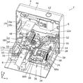
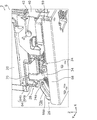
- FIG. 1 is a perspective view showing the external appearance of the printer according to the first embodiment.
- FIG. 2 is a perspective view showing the printing unit of the printer according to the first embodiment.
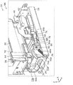
- FIG. 3 is a perspective view showing the printing unit of the printer according to the first embodiment with the head unit and the Y-axis drive mechanism omitted.
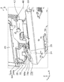
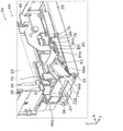
- FIG. 4 is a side view showing the printing unit of the printer according to the first embodiment with the nozzle cap in the second position.
- FIG. 5 is a perspective view showing the printing unit of the printer according to the first embodiment with the nozzle cap in the second position.
- FIG. 6 is an enlarged view showing a part of the printing unit of the printer according to the first embodiment with the nozzle cap in the second position.
- FIG. 1 is a perspective view showing the external appearance of the printer according to the first embodiment.
- FIG. 2 is a perspective view showing the printing unit of the printer according to the first embodiment.
- FIG. 3 is a perspective view showing the printing unit of the printer according to the first embodiment with the head
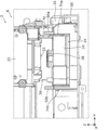
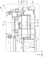
- FIG. 7 is a side view showing the printing unit of the printer according to the first embodiment with the nozzle cap in the first position.
- FIG. 8 is a perspective view showing the printing unit of the printer according to the first embodiment with the nozzle cap in the first position.
- FIG. 9 is an enlarged view showing a part of the printing unit of the printer according to the first embodiment with the nozzle cap in the first position.
- FIG. 10 is a perspective view showing the printing unit of the printer according to the second embodiment with the nozzle cap in the first position.
- FIG. 11 is a perspective view showing the printing unit of the printer according to the second embodiment with the nozzle cap in the third position.
- FIG. 12 is a perspective view showing the printing unit of the printer according to the second embodiment with the nozzle cap in the second position.
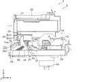
- FIG. 13 is a side view showing the printing unit of the printer according to the second embodiment with the nozzle cap in the third position.
- FIG. 14 is an enlarged view of a part of the printing unit of the printer according to the second embodiment with the
- FIG. 1 is a perspective view showing the appearance of the printer 2 according to the first embodiment.
- FIG. 2 is a perspective view showing the printing unit 6 of the printer 2 according to the first embodiment. For convenience of description, a part of the housing 4 is not shown in FIG.
- the printer 2 includes a housing 4 and a printing unit 6 arranged inside the housing 4.
- the printer 2 is a so-called nail printer for printing nails 10 (an example of an object) of the fingers 8 of the user's hand for nail polish such as color or pattern.
- the printer 2 can wirelessly communicate with an external terminal (not shown) such as a smartphone or a tablet terminal.
- the user can operate the printer 2 by using the application software installed in the external terminal as an interface.
- the housing 4 is made of resin, for example, and is formed in a box shape.
- a power switch 12 for turning on/off the power of the printer 2 is arranged on the top surface 4 a of the housing 4.
- an opening 14 for inserting a user's finger 8 is arranged on the front surface 4b of the housing 4.
- a finger holder 16 for placing the user's finger 8 is disposed below the opening 14 (negative side of the Z axis).
- a pressing cover 18 for pressing the user's finger 8 from above is arranged on the upper side (the positive side of the Z axis) of the opening 14.
- the finger holder 16 is movable in the up-down direction (Z-axis direction) with respect to the pressing cover 18, and is biased by a spring (not shown) in a direction approaching the pressing cover 18.
- a mirror 17 is arranged on the side of the finger holder 16.
- the mirror 17 is a side-view mirror having a mirror surface 17a for reflecting the side surface of the nail 10 of the finger 8 placed on the finger holder 16.
- the mirror 17 is arranged so as to incline with respect to the vertical direction (Z-axis direction) so that its mirror surface 17a is directed obliquely upward.
- the user inserts the finger 8 into the opening 14 (see FIG. 1) of the housing 4 in a state where the finger 8 is straightened with the nail 10 of the finger 8 facing upward, and the finger 8 The ventral side of is placed on the finger holder 16.
- the portion of the finger 8 including the nail 10 (for example, the portion from the tip of the finger 8 to the vicinity of the first joint) is arranged inside the housing 4.
- the finger holder 16 is urged in a direction of approaching the pressing cover 18, so that, for example, the vicinity of the first joint of the finger 8 is clamped by the finger holder 16 and the pressing cover 18 from above and below.
- the nail 10 of the finger 8 arranged inside the housing 4 is imaged by the camera unit 19 arranged above the finger holder 16 so as to face it.
- the camera unit 19 has a wiring board 19a which is arranged above the finger holder 16 so as to face it, and an imaging section 19b which is mounted on the lower surface of the wiring board 19a.
- the wiring board 19a is supported by, for example, an inner cover (not shown) arranged inside the housing 4.
- the imaging unit 19b directly images the front surface of the fingernail 10 of the finger 8 placed on the finger holder 16 and also images the side surface of the fingernail 10 of the finger 8 reflected on the mirror surface 17a of the mirror 17.
- the image data of the nail 10 captured by the image capturing unit 19b is wirelessly transmitted from the printer 2 to the external terminal and displayed on the display unit of the external terminal.
- the user confirms the position of the nail 10 in the finger holder 16 by looking at the image data of the nail 10 displayed on the display unit of the external terminal.
- the printing unit 6 is a unit for performing nail polish printing on the nail 10 of the finger 8 arranged inside the housing 4.
- the printing method of the printing unit 6 is an inkjet method in which printing is performed by spraying mist-like ink on the nail 10 of the finger 8.
- the printing unit 6 includes a head unit 20, a driving mechanism 22, a head maintaining mechanism 24, an interlocking mechanism 26 (see FIG. 4, which will be described later), and a lock mechanism 28 (see FIGS. 3 and 4, which will be described later). 4)).
- the head section 20 has a head support section 30 and an ink head 31 mounted on the head support section 30.
- the ink head 31 is filled with a plurality of colors of ink.
- a nozzle surface 32 (see FIGS. 4 and 6 described later) that ejects ink downward toward the nail 10 of the finger 8 is formed on the lower surface of the head unit 20.
- the drive mechanism 22 is a mechanism for two-dimensionally moving the head unit 20 in the first direction (X-axis direction) and the second direction (Y-axis direction) substantially orthogonal to the first direction. The specific configuration of the drive mechanism 22 will be described later.
- the head maintaining mechanism 24 is a mechanism for maintaining the nozzle surface 32 of the head unit 20.
- the head maintaining mechanism 24 is arranged on one side (the positive side of the Y axis) of the central part in the movement range of the head part 20 in the second direction, and is arranged below the nozzle surface 32 of the head part 20. Has been done.
- the head maintaining mechanism 24 has a cap support portion 34, a nozzle cap 36, and a wiper 38.
- the cap support portion 34 is movable in a direction toward the nozzle surface 32 of the head portion 20 and a direction away from the nozzle surface 32.
- the nozzle cap 36 is a cap for capping (sealing) the nozzle surface 32 of the head portion 20 at the standby position (described later), and is supported by the cap support portion 34.
- the wiper 38 is a wiper blade for wiping (cleaning) the nozzle surface 32 of the head portion 20, and is supported by the cap support portion 34.
- the wiper 38 is formed of, for example, flexible rubber or elastomer resin.
- the interlocking mechanism 26 interlocks with the movement of the head portion 20 from one side to the other side (from the negative side of the X axis to the positive side) in the first direction, and moves the head of the nozzle cap 36 supported by the cap supporting portion 34. This is a mechanism for moving the portion 20 in a direction approaching the nozzle surface 32.
- the specific configuration of the interlocking mechanism 26 will be described later.
- the lock mechanism 28 is a mechanism for restricting the movement of the head portion 20 in the first direction and the second direction when the nozzle cap 36 caps the nozzle surface 32 of the head portion 20.
- the specific configuration of the lock mechanism 28 will be described later.
- FIG. 3 is a perspective view showing the printing unit 6 of the printer 2 according to the first embodiment with the head unit 20 and the Y-axis drive mechanism 22b omitted.
- the drive mechanism 22 has an X-axis drive mechanism 22a for moving the head unit 20 in the first direction and a Y-axis drive mechanism 22b for moving the head unit 20 in the second direction.
- the Y-axis drive mechanism 22b includes a moving table 40, a Y-axis guide shaft 42, a Y-axis motor 44, and a timing belt 46.
- the Y-axis guide shaft 42 is supported by the moving table 40 arranged inside the housing 4, and extends in a long shape in the second direction.
- the head unit 20 is movably supported on the Y-axis guide shaft 42.
- the Y-axis motor 44 is composed of, for example, a servo motor, and is supported on the lower surface of the moving table 40.
- the driving force of the Y-axis motor 44 is transmitted to the head unit 20 via the timing belt 46.
- the head unit 20 reciprocates in the second direction along the Y-axis guide shaft 42 with respect to the moving table 40.
- the X-axis drive mechanism 22a includes a moving table 40 (see FIG. 2), a bearing member 48, an X-axis guide shaft 50, an X-axis motor 52 (an example of a drive source), and a worm gear 54. , A worm wheel 56, and a drive conversion mechanism 58.
- the X-axis guide shaft 50 is supported by a support plate 59 arranged inside the housing 4, and extends in a long direction in the first direction.
- a bearing member 48 fixed to the lower surface of the moving table 40 is movably supported on the X-axis guide shaft 50. That is, the moving table 40 is movably supported by the X-axis guide shaft 50 via the bearing member 48.
- the X-axis motor 52 is composed of, for example, a servo motor, and is supported by the support plate 59.
- the worm gear 54 is rotatably supported by the drive shaft of the X-axis motor 52.
- the worm wheel 56 is rotatably supported by the support plate 59 and meshes with the worm gear 54.
- the drive conversion mechanism 58 is a mechanism for converting rotation of the worm wheel 56 into linear movement of the head unit 20 in the first direction.
- the drive converting mechanism 58 includes a pinion gear 60 formed on the worm wheel 56 and a rack gear 62 formed on the bearing member 48.
- the pinion gear 60 and the rack gear 62 are meshed with each other.
- the driving force of the X-axis motor 52 is transmitted to the moving table 40 via the worm gear 54, the worm wheel 56, the pinion gear 60 and the rack gear 62.
- the head unit 20 reciprocates in the first direction along the X-axis guide shaft 50 integrally with the moving table 40.
- the nozzle surface of the head portion 20 is in a state in which the head portion 20 is reciprocating in the second direction and is moving from the other side to the one side (from the positive side to the negative side of the X axis) in the first direction.
- Ink is ejected from 32 toward the nail 10 of the finger 8 to print on the nail 10 of the finger 8.
- the head unit 20 moves from the current position from the other side to the one side in the first direction (from the plus side to the minus side of the X axis) and then from the other side to the one side in the second direction. It moves from the minus side of the Y-axis to the plus side, and temporarily stops at the position shown in FIG. 2 and FIG. 4 described later (hereinafter referred to as “relay position”). After that, the head unit 20 moves from one side to the other side (from the negative side of the X-axis to the positive side) in the first direction, and stops at a position shown in FIG. 7 (hereinafter, referred to as “standby position”) described later. To do.
- FIG. 4 is a side view showing the printing unit 6 of the printer 2 according to the first embodiment with the nozzle cap 36 in the second position.
- FIG. 5 is a perspective view showing the printing unit 6 of the printer 2 according to the first embodiment with the nozzle cap 36 in the second position.
- FIG. 6 is an enlarged view showing a part of the printing unit 6 of the printer 2 according to the first embodiment with the nozzle cap 36 in the second position.
- FIG. 7 is a side view showing the printing unit 6 of the printer 2 according to the first embodiment with the nozzle cap 36 in the first position.
- FIG. 8 is a perspective view showing the printing unit 6 of the printer 2 according to the first embodiment with the nozzle cap 36 in the first position.
- FIG. 9 is an enlarged view showing a part of the printing unit 6 of the printer 2 according to the first embodiment with the nozzle cap 36 in the first position.
- illustration of the housing 4 and the like is omitted in FIGS. 4 to 9.
- the interlocking mechanism 26 includes a first engagement portion 64, a pair of guide plates 66a and 66b, a cap support portion 34, a biasing member 68 (see FIG. 7), It has the 2nd engaging part 70.
- the first engaging portion 64 is formed at the lower end portion on the side surface of the head portion 20.
- the shape of the first engaging portion 64 in the XY cross section is formed into a substantially L shape. That is, the first engagement portion 64 includes a first wall portion 64a extending substantially vertically from the side surface of the head portion 20, and a second wall portion 64b extending substantially vertically from the tip portion of the first wall portion 64a. And have. That is, the second wall portion 64b is arranged so as to face the side surface of the head portion 20.
- the pair of guide plates 66a and 66b are supported by the support plate 59 and are arranged at intervals in the second direction.
- Guide holes 72a and 72b are formed in the pair of guide plates 66a and 66b, respectively.
- Each of the guide holes 72a and 72b extends so as to incline upward from one side in the first direction to the other side (from the negative side of the X axis to the positive side).
- protrusions 74a and 74b are formed on a pair of side surfaces of the cap support portion 34 that face each other in the second direction.
- the protrusions 74a and 74b are movably inserted into the guide holes 72a and 72b, respectively.
- the protrusions 74a and 74b move along the guide holes 72a and 72b, respectively, so that the nozzle cap 36 moves to the first position (the position shown in FIGS. 7 to 9) where the nozzle surface 32 of the head portion 20 is capped. , Away from the nozzle surface 32 and a second position (the position shown in FIGS. 4 to 6) for releasing the capping of the nozzle surface 32.
- the biasing member 68 is composed of, for example, a coil spring, and biases the nozzle cap 36 from the first position to the second position.
- One end of the biasing member 68 is supported by one side surface of the cap support portion 34, and the other end of the biasing member 68 is supported by the support plate 59.
- the second engagement portion 70 is formed in a plate shape, and extends from the upper end portion of one side surface of the cap support portion 34 toward the head portion 20. When the head portion 20 moves from the relay position to the standby position, the second engagement portion 70 is engaged with the first engagement portion 64.
- the second engagement portion 70 is engaged with the first wall portion 64 a of the first engagement portion 64 at the timing when the second intermediate portion 70 is reached.
- the head portion 20 further waits from the intermediate position.
- the nozzle cap 36 moves from the second position toward the first position in association with the movement of the head portion 20 while resisting the urging force of the urging member 68.
- the nozzle cap 36 reaches the first position and caps the nozzle surface 32 of the head unit 20.
- the head unit 20 moves from the standby position to the relay position at the start of printing, the engagement between the first wall portion 64a of the first engagement portion 64 and the second engagement portion 70 is performed. Is released. As a result, the nozzle cap 36 moves from the first position to the second position by the urging force of the urging member 68.
- the lock mechanism 28 to restrict the movement of the head portion 20 in the first direction when the nozzle cap 36 is in the first position will be described.
- the lock mechanism 28 is realized by the worm gear 54 and the worm wheel 56.
- the lead helix angle of the worm gear 54 is set to be equal to or less than the friction angle, when the rotation of the worm gear 54 and the worm wheel 56 is stopped, the frictional resistance generated on the meshing tooth surface of the worm gear 54 causes Thus, the so-called self-locking, in which the worm gear 54 cannot be rotated from the worm wheel 56 side, comes into operation. That is, when the driving of the X-axis motor 52 is stopped, the rotation of the worm gear 54 is self-locked even when an external force is applied to the head unit 20. 20 is held in the standby position.
- the lock mechanism 28 restricts the movement of the head portion 20 in the first direction by using the self-locking of the worm gear 54 with the nozzle cap 36 in the first position.
- the lock mechanism 28 for restricting the movement of the head portion 20 in the second direction when the nozzle cap 36 is in the first position will be described.
- the lock mechanism 28 is realized by the first engaging portion 64 and the second engaging portion 70.
- the head portion 20 when the head portion 20 is at the standby position, the second wall portion 64b of the first engaging portion 64 and the second engaging portion 70 are engaged with each other. Therefore, even when an external force is applied to the head portion 20 from one side to the other side (the positive side of the Y axis to the negative side) in the second direction, the head portion 20 is held at the standby position.
- the lock mechanism 28 utilizes the engagement between the first engaging portion 64 and the second engaging portion 70 while the nozzle cap 36 is in the first position, and the head portion is provided. The movement of 20 in the second direction is restricted.
- the lock mechanism 28 restricts the movement of the head portion 20 in the first direction and the second direction when the nozzle cap 36 is in the first position. Thereby, even if the printer 2 is vibrated when carrying the printer 2, for example, the head unit 20 is prevented from moving unintentionally in the first direction and the second direction with respect to the nozzle cap 36. be able to. As a result, the nozzle cap 36 can be prevented from coming off the nozzle surface 32 of the head portion 20, and the nozzle surface 36 of the head portion 20 can be reliably capped by the nozzle cap 36.
- FIG. 10 is a perspective view showing the printing unit 6A of the printer 2A according to the second embodiment with the nozzle cap 36 in the first position.
- FIG. 11 is a perspective view showing the printing unit 6A of the printer 2A according to the second embodiment with the nozzle cap 36 in the third position.
- FIG. 12 is a perspective view showing the printing unit 6A of the printer 2A according to the second embodiment with the nozzle cap 36 in the second position.
- the same components as those in the first embodiment are designated by the same reference numerals, and the description thereof will be omitted.
- the printer 2A differs from the first embodiment in that the printing unit 6A has a holding mechanism 76.
- the holding mechanism 76 positions the nozzle cap 36 at a third position (FIG. 11 and later-described FIGS. 13 and 13) between the first position (the position shown in FIG. 10) and the second position (the position shown in FIG. 12). This is a mechanism for holding it at the position (14).
- the holding mechanism 76 has a lever member 78, a biasing member 68A, and a claw member 80. The wiping of the nozzle surface 32 of the head unit 20 by the wiper 38 is performed while the holding mechanism 76 holds the nozzle cap 36 at the third position.
- the lever member 78 is formed in a horizontally long plate shape. One end portion of the lever member 78 in the longitudinal direction is rotatably supported by a rotation shaft portion 82 arranged on one side surface of the cap support portion 34. The lever member 78 extends from the rotating shaft portion 82 to the other side (the positive side of the X axis) in the first direction. That is, the lever member 78 is rotatable about the rotation shaft portion 82 in the vertical direction (in the XZ plane). A cutout portion 84 that extends in the longitudinal direction of the lever member 78 is formed on one side surface of the lever member 78 in the lateral direction (side surface facing the head portion 20).
- One end of the biasing member 68A is supported by one end of the lever member 78, and the other end of the biasing member 68A is supported by the support plate 59.
- the claw member 80 is formed on the upper end portion of the support wall portion 86 that is erected on the upper surface of the support plate 59.
- the claw member 80 engages with one end portion 84a (the end portion on the side closer to the rotation shaft portion 82) and the other end portion 84b (the end portion on the side far from the rotation shaft portion 82) of the cutout portion 84 of the lever member 78. It is possible.
- FIG. 13 is a side view showing the printing unit 6A of the printer 2A according to the second embodiment with the nozzle cap 36 in the third position.
- FIG. 14 is an enlarged view showing a part of the printing unit 6A of the printer 2A according to the second embodiment when the nozzle cap 36 is at the third position.
- the nozzle cap 36 moves the nozzle surface 32 (see FIG. 9 described above) of the head unit 20 at the first position. I'm capping.
- the claw member 80 is engaged with the one end portion 84a of the cutout portion 84 of the lever member 78.
- the head unit 20 moves from the other side to the one side in the first direction (from the positive side to the negative side of the X-axis) in the first direction with the nozzle cap 36 in the first position at the start of printing
- the nozzle cap 36 moves from the first position to the third position by the urging force of the urging member 68A.
- the lever member 78 rotates, and the claw member 80 engages with the other end portion 84b of the cutout portion 84 of the lever member 78, whereby the movement of the nozzle cap 36 is stopped and the nozzle cap 36 is moved to the first position. It is held in position 3.
- the engagement between the first engaging portion 64 and the second engaging portion 70 is released.
- the head portion 20 reciprocates in the second direction with respect to the nozzle cap 36, so that the nozzle surface 32 of the head portion 20. Are wiped by the wiper 38. That is, when the nozzle cap 36 is held at the third position, the nozzle surface 32 of the head portion 20 is held at a position where wiping by the wiper 38 is possible. During wiping, the tip of the wiper 38 comes into contact with the nozzle surface 32 of the head portion 20, so that the wiper 38 elastically deforms in a curved shape in the second direction.
- the head unit 20 moves in the second direction and returns to the position shown in FIG.
- the moving table 40 Is brought into contact with the other end of the lever member 78, the lever member 78 is rotated and the engagement between the lever member 78 and the claw member 80 is released.
- the nozzle cap 36 moves from the third position to the second position by the urging force of the urging member 68A.
- the tip portion of the wiper 38 causes the tip surface of the wiper 38 to move to the nozzle surface 32 of the head portion 20. Do not touch.
- the printer 2 (2A) prints on the nail 10 of the finger 8 of the user's hand, but the invention is not limited to this.
- printing is performed on an arbitrary object such as a golf ball. You may do it.
- the present invention can be applied as, for example, a printer for printing nail polish on the fingernails of the user's hand.
- 2,2A printer 4 housing 4a top surface 4b front surface 6,6A printing unit 8 finger 10 nail 12 power switch 14 opening 16 finger holder 17 mirror 17a mirror surface 18 holding cover 19 camera unit 19a wiring board 19b image pickup section 20 head section 22 Drive mechanism 22a X-axis drive mechanism 22b Y-axis drive mechanism 24 Head maintaining mechanism 26 Interlocking mechanism 28 Lock mechanism 30 Head support 31 Ink head 32 Nozzle surface 34 Cap support 36 Nozzle cap 38 Wiper 40 Moving table 42 Y-axis guide shaft 44 Y-axis motor 46 Timing belt 48 Bearing member 50 X-axis guide shaft 52 X-axis motor 54 Worm gear 56 Worm wheel 58 Drive conversion mechanism 59 Support plate 60 Pinion gear 62 Rack gear 64 First engagement portion 64a First wall portion 64b 2nd wall part 66a, 66b Guide plate 68, 68A Energizing member 70 2nd engaging part 72a, 72b Guide hole 74a, 74b Protrusion 76 Holding mechanism 78 Lever member 80 Claw member 82 Rotating shaft part 84
Landscapes
- Ink Jet (AREA)
Abstract
プリンタ(2)は、対象物に向けてインクを吐出するノズル面(32)を有するヘッド部(20)と、ヘッド部(20)を第1の方向及び第1の方向と略直交する第2の方向に移動させる駆動機構(22)と、ノズル面(32)をキャッピングする第1の位置及びノズル面(32)のキャッピングを解除する第2の位置との間を移動可能なノズルキャップ(36)と、ノズルキャップ(36)が第1の位置にある状態で、ヘッド部(20)の第1の方向及び第2の方向における移動を規制するロック機構(28)とを備える。
Description
本発明は、対象物に印刷を施すためのプリンタに関する。
インクジェット方式によりユーザの手の指の爪に、例えば色又は絵柄等のマニキュア用の印刷を施すためのプリンタが知られている(例えば、特許文献1参照)。この種のプリンタは、指の爪に向けてインクを吐出するノズル面を有するヘッド部と、ヘッド部を第1の方向及び当該第1の方向と略直交する第2の方向に移動させる駆動機構とを備えている。
また、この種のプリンタでは、ヘッド部が待機位置にある状態で、ノズル面が乾燥して目詰まりを起こすのを抑制するために、ノズル面をノズルキャップでキャッピングするように構成されている。
上述したプリンタは、例えば家屋内のいろいろな場所に持ち運ばれて使用される。しかしながら、プリンタを持ち運ぶ際の振動によって、ヘッド部がノズルキャップに対して第1の方向及び第2の方向に不意に動いてしまうことにより、ノズルキャップがノズル面から外れるおそれがあるという課題が生じる。
本発明は、上述した課題を解決しようとするものであり、その目的は、ノズルキャップによりヘッド部のノズル面を確実にキャッピングすることができるプリンタを提供することである。
上記目的を達成するために、本発明の一態様に係るプリンタは、対象物に印刷を施すためのプリンタであって、前記対象物に向けてインクを吐出するノズル面を有するヘッド部と、前記ヘッド部を第1の方向及び前記第1の方向と略直交する第2の方向に移動させる駆動機構と、前記ノズル面をキャッピングする第1の位置と、前記ノズル面のキャッピングを解除する第2の位置との間を移動可能なノズルキャップと、前記ノズルキャップが前記第1の位置にある状態で、前記ヘッド部の前記第1の方向及び前記第2の方向における移動を規制するロック機構と、を備える。
本態様によれば、ロック機構は、ノズルキャップが第1の位置にある状態で、ヘッド部の第1の方向及び第2の方向における移動を規制する。これにより、例えばプリンタを持ち運ぶ際にプリンタに振動が加わった場合であっても、ヘッド部がノズルキャップに対して第1の方向及び第2の方向に不意に動くのを抑制することができる。その結果、ノズルキャップがヘッド部のノズル面から外れるのを抑制することができ、ノズルキャップによりヘッド部のノズル面を確実にキャッピングすることができる。
例えば、本発明の一態様に係るプリンタにおいて、前記駆動機構は、駆動源と、前記駆動源により回転するウォームギアと、前記ウォームギアと噛み合うウォームホイールと、前記ウォームホイールの回転を前記ヘッド部の前記第1の方向における移動に変換する駆動変換機構と、を有し、前記ロック機構は、前記ノズルキャップが前記第1の位置にある状態で、前記ウォームギアのセルフロックを利用して、前記ヘッド部の前記第1の方向における移動を規制するように構成してもよい。
本態様によれば、ロック機構は、ノズルキャップが第1の位置にある状態で、ウォームギアのセルフロックを利用して、ヘッド部の第1の方向における移動を規制するので、駆動機構をロック機構として兼用することができる。その結果、プリンタの部品点数を抑えることができ、プリンタの小型化を図ることができる。
例えば、本発明の一態様に係るプリンタにおいて、前記プリンタは、さらに、前記ヘッド部の前記第1の方向における一方側から他方側への移動に連動して、前記ノズルキャップを前記第2の位置から前記第1の位置に移動させる連動機構を備えるように構成してもよい。
本態様によれば、連動機構によって、ヘッド部の移動に連動してノズルキャップを第2の位置から第1の位置に移動させることができる。
例えば、本発明の一態様に係るプリンタにおいて、前記連動機構は、前記ヘッド部に設けられた第1の係合部と、前記ノズルキャップを支持するキャップ支持部と、前記キャップ支持部に設けられ、前記第1の係合部と係合可能な第2の係合部と、を有し、前記ヘッド部が前記第1の方向における前記一方側から前記他方側へ移動した際に、前記第1の係合部が前記第2の係合部と係合することにより、前記ノズルキャップが前記ヘッド部の移動に連動して前記第2の位置から前記第1の位置に移動し、前記ロック機構は、前記ノズルキャップが前記第1の位置にある状態で、前記第1の係合部と前記第2の係合部との係合を利用して、前記ヘッド部の前記第2の方向における移動を規制するように構成してもよい。
本態様によれば、ロック機構は、ノズルキャップが第1の位置にある状態で、第1の係合部と第2の係合部との係合を利用して、ヘッド部の第2の方向における移動を規制するので、連動機構をロック機構として兼用することができる。その結果、プリンタの部品点数を抑えることができ、プリンタの小型化を図ることができる。
例えば、本発明の一態様に係るプリンタにおいて、前記プリンタは、さらに、前記ノズルキャップを前記第1の位置と前記第2の位置との間の第3の位置に保持する保持機構と、前記キャップ支持部に支持されたワイパーと、を備え、前記ノズルキャップが前記第3の位置に保持された状態で、前記ヘッド部が前記ノズルキャップに対して前記第2の方向に移動することにより、前記ノズル面が前記ワイパーによりワイピングされるように構成してもよい。
本態様によれば、保持機構はノズルキャップを第3の位置に保持するので、ヘッド部のノズル面を、ワイパーによるワイピングが可能な位置に保持することができる。
例えば、本発明の一態様に係るプリンタにおいて、前記保持機構は、前記ノズルキャップを前記第1の位置から前記第2の位置に向けて付勢する付勢部材と、前記キャップ支持部に回動可能に支持されたレバー部材と、前記レバー部材と係合可能な爪部材と、を有し、前記ノズルキャップが前記第1の位置にある状態で、前記ヘッド部が前記第1の方向における前記他方側から前記一方側へ移動した際には、前記ノズルキャップが前記付勢部材の付勢力により前記第1の位置から前記第3の位置に向けて移動し、前記レバー部材が回動して前記爪部材と係合することにより、前記ノズルキャップが前記第3の位置に保持され、前記ノズルキャップが前記第3の位置に保持された状態で、前記ヘッド部がさらに前記第1の方向における前記他方側から前記一方側へ移動した際には、前記レバー部材が回動して前記レバー部材と前記爪部材との係合が解除されることにより、前記ノズルキャップが前記付勢部材の付勢力により前記第3の位置から前記第2の位置に移動するように構成してもよい。
本態様によれば、比較的簡単な構成で保持機構を実現することができる。
本発明の一態様に係るプリンタによれば、ノズルキャップによりヘッド部のノズル面を確実にキャッピングすることができる。
以下、本発明の実施の形態について、図面を用いて詳細に説明する。なお、以下で説明する実施の形態は、いずれも包括的または具体的な例を示すものである。以下の実施の形態で示される数値、形状、材料、構成要素、構成要素の配置位置及び接続形態などは、一例であり、本発明を限定する主旨ではない。また、以下の実施の形態における構成要素のうち、独立請求項に記載されていない構成要素については、任意の構成要素として説明される。
(実施の形態1)
[1-1.プリンタの構成]
まず、図1及び図2を参照しながら、実施の形態1に係るプリンタ2の構成について説明する。図1は、実施の形態1に係るプリンタ2の外観を示す斜視図である。図2は、実施の形態1に係るプリンタ2の印刷ユニット6を示す斜視図である。なお、説明の都合上、図2では、筐体4の一部の図示を省略してある。
[1-1.プリンタの構成]
まず、図1及び図2を参照しながら、実施の形態1に係るプリンタ2の構成について説明する。図1は、実施の形態1に係るプリンタ2の外観を示す斜視図である。図2は、実施の形態1に係るプリンタ2の印刷ユニット6を示す斜視図である。なお、説明の都合上、図2では、筐体4の一部の図示を省略してある。
図1及び図2に示すように、プリンタ2は、筐体4と、筐体4の内部に配置された印刷ユニット6とを備えている。本実施の形態では、プリンタ2は、ユーザの手の指8の爪10(対象物の一例)に例えば色又は絵柄等のマニキュア用の印刷を施すための、いわゆるネイルプリンタである。
なお、プリンタ2は、例えばスマートフォン又はタブレット端末等の外部端末(図示せず)と無線通信可能である。ユーザは、外部端末にインストールされたアプリケーションソフトウェアをインタフェースとして用いることにより、プリンタ2を操作することができる。
図1に示すように、筐体4は、例えば樹脂製であり、箱形状に形成されている。筐体4の天面4aには、プリンタ2の電源をオン・オフするための電源スイッチ12が配置されている。
図1に示すように、筐体4の前面4bには、ユーザの指8を挿入するための開口部14が配置されている。図1及び図2に示すように、開口部14の下側(Z軸のマイナス側)には、ユーザの指8を載置するためのフィンガーホルダ16が配置されている。また、図1に示すように、開口部14の上側(Z軸のプラス側)には、ユーザの指8を上方から押さえるための押さえカバー18が配置されている。フィンガーホルダ16は、押さえカバー18に対して上下方向(Z軸方向)に移動可能であり、押さえカバー18に近付く方向にバネ(図示せず)で付勢されている。
なお、図2及び後述する図3に示すように、フィンガーホルダ16の側方には、ミラー17が配置されている。ミラー17は、フィンガーホルダ16に載置された指8の爪10の側面を映すための鏡面17aを有するサイドビューミラーである。ミラー17は、その鏡面17aが斜め上方を向くように、垂直方向(Z軸方向)に対して傾斜するように配置されている。
図2に示すように、ユーザは、指8の爪10が上側を向くようにして、指8を真っ直ぐに伸ばした状態で筐体4の開口部14(図1参照)に挿入し、指8の腹側をフィンガーホルダ16に載置する。これにより、指8の爪10を含む部分(例えば、指8の先端から第一関節の近傍までの部分)が筐体4の内部に配置される。この時、フィンガーホルダ16が押さえカバー18に近付く方向に付勢されることにより、例えば指8の第一関節付近がフィンガーホルダ16及び押さえカバー18により上下から挟持される。
なお、筐体4の内部に配置された指8の爪10は、フィンガーホルダ16の上方に対向して配置されたカメラユニット19により撮像される。カメラユニット19は、フィンガーホルダ16の上方に対向して配置された配線基板19aと、配線基板19aの下面に実装された撮像部19bとを有している。なお、配線基板19aは、例えば筐体4の内部に配置されたインナーカバー等(図示せず)に支持されている。撮像部19bは、フィンガーホルダ16に載置された指8の爪10の正面を直接撮像するとともに、ミラー17の鏡面17aに映った指8の爪10の側面を撮像する。撮像部19bにより撮像された爪10の画像データは、プリンタ2から外部端末に無線で送信され、当該外部端末の表示部に表示される。ユーザは、外部端末の表示部に表示された爪10の画像データを見ることにより、フィンガーホルダ16における爪10の位置を確認する。
印刷ユニット6は、筐体4の内部に配置された指8の爪10にマニキュア用の印刷を施すためのユニットである。印刷ユニット6の印刷方式は、指8の爪10にミスト状のインクを吹き付けることにより印刷を施すインクジェット方式である。
図2に示すように、印刷ユニット6は、ヘッド部20と、駆動機構22と、ヘッド維持機構24と、連動機構26(後述する図4参照)と、ロック機構28(後述する図3及び図4参照)とを有している。
ヘッド部20は、ヘッド支持部30と、ヘッド支持部30に搭載されたインクヘッド31とを有している。インクヘッド31の内部には、複数色のインクが充填されている。ヘッド部20の下面には、指8の爪10に向けて下方にインクを吐出するノズル面32(後述する図4及び図6参照)が形成されている。
駆動機構22は、ヘッド部20を、第1の方向(X軸方向)及び第1の方向と略直交する第2の方向(Y軸方向)に二次元的に移動させるための機構である。駆動機構22の具体的な構成については後述する。
ヘッド維持機構24は、ヘッド部20のノズル面32をメンテナンスするための機構である。ヘッド維持機構24は、ヘッド部20の第2の方向への移動範囲における中央部よりも一方側(Y軸のプラス側)に配置され、且つ、ヘッド部20のノズル面32よりも下方に配置されている。ヘッド維持機構24は、キャップ支持部34と、ノズルキャップ36と、ワイパー38とを有している。
キャップ支持部34は、ヘッド部20のノズル面32に近付く方向及びノズル面32から離れる方向に移動可能である。ノズルキャップ36は、待機位置(後述する)にあるヘッド部20のノズル面32をキャッピング(封止)するためのキャップであり、キャップ支持部34に支持されている。ワイパー38は、ヘッド部20のノズル面32をワイピング(清掃)するためのワイパーブレードであり、キャップ支持部34に支持されている。ワイパー38は、例えば可撓性を有するゴム又はエラストマー樹脂等で形成されている。
連動機構26は、ヘッド部20の第1の方向における一方側から他方側(X軸のマイナス側からプラス側)への移動に連動して、キャップ支持部34に支持されたノズルキャップ36をヘッド部20のノズル面32に近付く方向に移動させるための機構である。連動機構26の具体的な構成については後述する。
ロック機構28は、ノズルキャップ36がヘッド部20のノズル面32をキャッピングしている状態で、ヘッド部20の第1の方向及び第2の方向における移動を規制するための機構である。ロック機構28の具体的な構成については後述する。
[1-2.駆動機構の構成]
次に、図2及び図3を参照しながら、駆動機構22の構成について説明する。図3は、ヘッド部20及びY軸駆動機構22bを省略した状態での、実施の形態1に係るプリンタ2の印刷ユニット6を示す斜視図である。
次に、図2及び図3を参照しながら、駆動機構22の構成について説明する。図3は、ヘッド部20及びY軸駆動機構22bを省略した状態での、実施の形態1に係るプリンタ2の印刷ユニット6を示す斜視図である。
駆動機構22は、ヘッド部20を第1の方向に移動させるためのX軸駆動機構22aと、ヘッド部20を第2の方向に移動させるためのY軸駆動機構22bとを有している。
図2に示すように、Y軸駆動機構22bは、移動テーブル40と、Y軸ガイドシャフト42と、Y軸モータ44と、タイミングベルト46とを有している。
Y軸ガイドシャフト42は、筐体4の内部に配置された移動テーブル40に支持されており、第2の方向に長尺状に延びている。Y軸ガイドシャフト42には、ヘッド部20が移動可能に支持されている。Y軸モータ44は、例えばサーボモータで構成され、移動テーブル40の下面に支持されている。
Y軸モータ44の駆動力は、タイミングベルト46を介してヘッド部20に伝達される。これにより、ヘッド部20は、移動テーブル40に対して、Y軸ガイドシャフト42に沿って第2の方向に往復移動する。
図3に示すように、X軸駆動機構22aは、移動テーブル40(図2参照)と、ベアリング部材48と、X軸ガイドシャフト50と、X軸モータ52(駆動源の一例)と、ウォームギア54と、ウォームホイール56と、駆動変換機構58とを有している。
X軸ガイドシャフト50は、筐体4の内部に配置された支持プレート59に支持されており、第1の方向に長尺状に延びている。X軸ガイドシャフト50には、移動テーブル40の下面に固定されたベアリング部材48が移動可能に支持されている。すなわち、移動テーブル40は、ベアリング部材48を介してX軸ガイドシャフト50に移動可能に支持されている。X軸モータ52は、例えばサーボモータで構成され、支持プレート59に支持されている。ウォームギア54は、X軸モータ52の駆動軸に回転可能に支持されている。ウォームホイール56は、支持プレート59に回転可能に支持されており、ウォームギア54と噛み合わされている。
駆動変換機構58は、ウォームホイール56の回転をヘッド部20の第1の方向における直線移動に変換するための機構である。駆動変換機構58は、ウォームホイール56に形成されたピニオン歯車60と、ベアリング部材48に形成されたラック歯車62とを有している。ピニオン歯車60及びラック歯車62は、互いに噛み合わされている。
X軸モータ52の駆動力は、ウォームギア54、ウォームホイール56、ピニオン歯車60及びラック歯車62を介して移動テーブル40に伝達される。これにより、ヘッド部20は、移動テーブル40と一体的に、X軸ガイドシャフト50に沿って第1の方向に往復移動する。
ヘッド部20が第2の方向に往復移動しながら、第1の方向における他方側から一方側(X軸のプラス側からマイナス側)に向けて移動している状態で、ヘッド部20のノズル面32から指8の爪10に向けてインクが吐出されることにより、指8の爪10に印刷が施される。
なお、ヘッド部20は、印刷の終了後、現在位置から第1の方向における他方側から一方側(X軸のプラス側からマイナス側)に移動した後に、第2の方向における他方側から一方側(Y軸のマイナス側からプラス側)に移動し、図2及び後述する図4に示す位置(以下、「中継位置」という)で一旦停止する。さらにその後、ヘッド部20は、第1の方向における一方側から他方側(X軸のマイナス側からプラス側)に移動し、後述する図7に示す位置(以下、「待機位置」という)で停止する。
[1-3.連動機構の構成]
次に、図2及び図4~図9を参照しながら、連動機構26の構成について説明する。図4は、ノズルキャップ36が第2の位置にある状態での、実施の形態1に係るプリンタ2の印刷ユニット6を示す側面図である。図5は、ノズルキャップ36が第2の位置にある状態での、実施の形態1に係るプリンタ2の印刷ユニット6を示す斜視図である。図6は、ノズルキャップ36が第2の位置にある状態での、実施の形態1に係るプリンタ2の印刷ユニット6の一部を拡大して示す図である。
次に、図2及び図4~図9を参照しながら、連動機構26の構成について説明する。図4は、ノズルキャップ36が第2の位置にある状態での、実施の形態1に係るプリンタ2の印刷ユニット6を示す側面図である。図5は、ノズルキャップ36が第2の位置にある状態での、実施の形態1に係るプリンタ2の印刷ユニット6を示す斜視図である。図6は、ノズルキャップ36が第2の位置にある状態での、実施の形態1に係るプリンタ2の印刷ユニット6の一部を拡大して示す図である。
図7は、ノズルキャップ36が第1の位置にある状態での、実施の形態1に係るプリンタ2の印刷ユニット6を示す側面図である。図8は、ノズルキャップ36が第1の位置にある状態での、実施の形態1に係るプリンタ2の印刷ユニット6を示す斜視図である。図9は、ノズルキャップ36が第1の位置にある状態での、実施の形態1に係るプリンタ2の印刷ユニット6の一部を拡大して示す図である。なお、説明の都合上、図4~図9では、筐体4等の図示を省略してある。
図4~図6に示すように、連動機構26は、第1の係合部64と、一対のガイドプレート66a,66bと、キャップ支持部34と、付勢部材68(図7参照)と、第2の係合部70とを有している。
図4に示すように、第1の係合部64は、ヘッド部20の側面における下端部に形成されている。図5に示すように、第1の係合部64のXY断面における形状は、略L字状に形成されている。すなわち、第1の係合部64は、ヘッド部20の側面から略垂直に延びる第1の壁部64aと、第1の壁部64aの先端部からさらに略垂直に延びる第2の壁部64bとを有している。すなわち、第2の壁部64bは、ヘッド部20の側面に対向するように配置されている。
図2及び図4~図6に示すように、一対のガイドプレート66a,66bは、支持プレート59に支持されており、第2の方向に間隔を置いて配置されている。一対のガイドプレート66a,66bにはそれぞれ、ガイド用孔72a,72bが形成されている。ガイド用孔72a,72bの各々は、第1の方向における一方側から他方側(X軸のマイナス側からプラス側)に向けて上り傾斜するように延びている。
図2及び図4~図6に示すように、キャップ支持部34の第2の方向において対向する一対の側面にはそれぞれ、突起74a,74bが形成されている。突起74a,74bはそれぞれ、ガイド用孔72a,72bに移動可能に挿通されている。突起74a,74bがそれぞれガイド用孔72a,72bに沿って移動することにより、ノズルキャップ36は、ヘッド部20のノズル面32をキャッピングする第1の位置(図7~図9に示す位置)と、ノズル面32から離れてノズル面32のキャッピングを解除する第2の位置(図4~図6に示す位置)との間を移動する。
図7及び図8に示すように、付勢部材68は、例えばコイルバネで構成されており、ノズルキャップ36を第1の位置から第2の位置に向けて付勢する。付勢部材68の一端部はキャップ支持部34の一方の側面に支持され、付勢部材68の他端部は支持プレート59に支持されている。
図4及び図5に示すように、第2の係合部70は、プレート状に形成され、キャップ支持部34の一方の側面の上端部からヘッド部20に向けて延びている。ヘッド部20が中継位置から待機位置に移動した際に、第2の係合部70は第1の係合部64と係合される。
次に、図4~図9を参照しながら、連動機構26の動作について説明する。図4~図6に示すように、ヘッド部20が中継位置にある状態では、ノズルキャップ36は付勢部材68の付勢力により第2の位置に保持され、第1の係合部64と第2の係合部70との係合は解除されている。
ヘッド部20が中継位置から待機位置に向けて(第1の方向における一方側から他方側に向けて)移動した際に、ヘッド部20が中継位置と待機位置との間の位置(以下、「中間位置」という)に到達したタイミングで、第2の係合部70は第1の係合部64の第1の壁部64aと係合される。
図7~図9に示すように、第1の係合部64の第1の壁部64aと第2の係合部70とが係合された状態で、ヘッド部20がさらに中間位置から待機位置に向けて移動することにより、ノズルキャップ36は、付勢部材68の付勢力に抗しながら、ヘッド部20の移動に連動して第2の位置から第1の位置に向けて移動する。ヘッド部20が待機位置に到達したタイミングで、ノズルキャップ36は、第1の位置に到達して、ヘッド部20のノズル面32をキャッピングする。
なお、例えば印刷の開始時に、ヘッド部20が待機位置から中継位置に移動した際には、第1の係合部64の第1の壁部64aと第2の係合部70との係合が解除される。これにより、ノズルキャップ36は、付勢部材68の付勢力により、第1の位置から第2の位置に移動する。
[1-4.ロック機構の構成]
次に、ロック機構28の構成について説明する。
次に、ロック機構28の構成について説明する。
まず、図3を参照しながら、ノズルキャップ36が第1の位置にある状態で、ロック機構28がヘッド部20の第1の方向における移動を規制する機能について説明する。この場合、図3に示すように、ロック機構28は、ウォームギア54及びウォームホイール56により実現される。
具体的には、ウォームギア54のリードねじれ角が摩擦角以下に設定されているため、ウォームギア54及びウォームホイール56の各回転が停止している状態では、ウォームギア54の噛み合い歯面に生じる摩擦抵抗により、ウォームホイール56側からウォームギア54を回転させることができない、いわゆるセルフロックが働くようになる。すなわち、X軸モータ52の駆動が停止している状態では、ヘッド部20に第1の方向への外力が加えられた場合であっても、ウォームギア54の回転がセルフロックされるため、ヘッド部20は待機位置に保持される。
以上のようにして、ロック機構28は、ノズルキャップ36が第1の位置にある状態で、ウォームギア54のセルフロックを利用して、ヘッド部20の第1の方向における移動を規制する。
次に、図8を参照しながら、ノズルキャップ36が第1の位置にある状態で、ロック機構28がヘッド部20の第2の方向における移動を規制する機能について説明する。この場合、図8に示すように、ロック機構28は、第1の係合部64及び第2の係合部70により実現される。
具体的には、ヘッド部20が待機位置にある状態では、第1の係合部64の第2の壁部64bと第2の係合部70とが係合される。そのため、ヘッド部20に第2の方向における一方側から他方側(Y軸のプラス側からマイナス側)への外力が加えられた場合であっても、ヘッド部20は待機位置に保持される。
以上のようにして、ロック機構28は、ノズルキャップ36が第1の位置にある状態で、第1の係合部64と第2の係合部70との係合を利用して、ヘッド部20の第2の方向における移動を規制する。
[1-5.効果]
上述したように、ロック機構28は、ノズルキャップ36が第1の位置にある状態で、ヘッド部20の第1の方向及び第2の方向における移動を規制する。これにより、例えばプリンタ2を持ち運ぶ際にプリンタ2に振動が加わった場合であっても、ヘッド部20がノズルキャップ36に対して第1の方向及び第2の方向に不意に動くのを抑制することができる。その結果、ノズルキャップ36がヘッド部20のノズル面32から外れるのを抑制することができ、ノズルキャップ36によりヘッド部20のノズル面32を確実にキャッピングすることができる。
上述したように、ロック機構28は、ノズルキャップ36が第1の位置にある状態で、ヘッド部20の第1の方向及び第2の方向における移動を規制する。これにより、例えばプリンタ2を持ち運ぶ際にプリンタ2に振動が加わった場合であっても、ヘッド部20がノズルキャップ36に対して第1の方向及び第2の方向に不意に動くのを抑制することができる。その結果、ノズルキャップ36がヘッド部20のノズル面32から外れるのを抑制することができ、ノズルキャップ36によりヘッド部20のノズル面32を確実にキャッピングすることができる。
(実施の形態2)
[2-1.プリンタの構成]
図10~図12を参照しながら、実施の形態2に係るプリンタ2Aの構成について説明する。図10は、ノズルキャップ36が第1の位置にある状態での、実施の形態2に係るプリンタ2Aの印刷ユニット6Aを示す斜視図である。図11は、ノズルキャップ36が第3の位置にある状態での、実施の形態2に係るプリンタ2Aの印刷ユニット6Aを示す斜視図である。図12は、ノズルキャップ36が第2の位置にある状態での、実施の形態2に係るプリンタ2Aの印刷ユニット6Aを示す斜視図である。なお、本実施の形態において、上記実施の形態1と同一の構成要素には同一の符号を付して、その説明を省略する。
[2-1.プリンタの構成]
図10~図12を参照しながら、実施の形態2に係るプリンタ2Aの構成について説明する。図10は、ノズルキャップ36が第1の位置にある状態での、実施の形態2に係るプリンタ2Aの印刷ユニット6Aを示す斜視図である。図11は、ノズルキャップ36が第3の位置にある状態での、実施の形態2に係るプリンタ2Aの印刷ユニット6Aを示す斜視図である。図12は、ノズルキャップ36が第2の位置にある状態での、実施の形態2に係るプリンタ2Aの印刷ユニット6Aを示す斜視図である。なお、本実施の形態において、上記実施の形態1と同一の構成要素には同一の符号を付して、その説明を省略する。
図10~図12に示すように、本実施の形態のプリンタ2Aでは、印刷ユニット6Aが保持機構76を有している点で、上記実施の形態1と異なっている。保持機構76は、ノズルキャップ36を第1の位置(図10に示す位置)と第2の位置(図12に示す位置)との間の第3の位置(図11並びに後述する図13及び図14に示す位置)に保持するための機構である。保持機構76は、レバー部材78と、付勢部材68Aと、爪部材80とを有している。なお、保持機構76がノズルキャップ36を第3の位置に保持している状態で、ワイパー38によるヘッド部20のノズル面32のワイピングが実行される。
レバー部材78は、横長のプレート状に形成されている。レバー部材78の長手方向における一端部は、キャップ支持部34の一方の側面に配置された回動軸部82に回動可能に支持されている。レバー部材78は、回動軸部82から第1の方向における他方側(X軸のプラス側)に延びている。すなわち、レバー部材78は、回動軸部82を中心に、上下方向に(XZ平面内で)回動可能である。レバー部材78の短手方向における一方の側面(ヘッド部20に対向する側の側面)には、レバー部材78の長手方向に延びる切り欠き部84が形成されている。
付勢部材68Aの一端部はレバー部材78の一端部に支持され、付勢部材68Aの他端部は支持プレート59に支持されている。
爪部材80は、支持プレート59の上面に立設された支持壁部86の上端部に形成されている。爪部材80は、レバー部材78の切り欠き部84の一端部84a(回動軸部82に近い側の端部)及び他端部84b(回動軸部82から遠い側の端部)と係合可能である。
[2-2.保持機構の動作]
次に、図10~図14を参照しながら、保持機構76の動作について説明する。図13は、ノズルキャップ36が第3の位置にある状態での、実施の形態2に係るプリンタ2Aの印刷ユニット6Aを示す側面図である。図14は、ノズルキャップ36が第3の位置にある状態での、実施の形態2に係るプリンタ2Aの印刷ユニット6Aの一部を拡大して示す図である。
次に、図10~図14を参照しながら、保持機構76の動作について説明する。図13は、ノズルキャップ36が第3の位置にある状態での、実施の形態2に係るプリンタ2Aの印刷ユニット6Aを示す側面図である。図14は、ノズルキャップ36が第3の位置にある状態での、実施の形態2に係るプリンタ2Aの印刷ユニット6Aの一部を拡大して示す図である。
図10に示すように、ヘッド部20が待機位置にある状態では、ノズルキャップ36(上述した図9参照)は、第1の位置においてヘッド部20のノズル面32(上述した図9参照)をキャッピングしている。この時、爪部材80は、レバー部材78の切り欠き部84の一端部84aと係合している。
例えば印刷の開始時に、ノズルキャップ36が第1の位置にある状態で、ヘッド部20が第1の方向における他方側から一方側(X軸のプラス側からマイナス側)へ移動した際には、図11、図13及び図14に示すように、ノズルキャップ36は、付勢部材68Aの付勢力により第1の位置から第3の位置に向けて移動する。この時、レバー部材78が回動して、爪部材80がレバー部材78の切り欠き部84の他端部84bと係合することにより、ノズルキャップ36の移動が停止し、ノズルキャップ36が第3の位置に保持される。また、この時、第1の係合部64と第2の係合部70との係合は解除されている。
図14に示すように、ノズルキャップ36が第3の位置に保持された状態で、ヘッド部20がノズルキャップ36に対して第2の方向に往復移動することにより、ヘッド部20のノズル面32がワイパー38によりワイピングされる。すなわち、ノズルキャップ36が第3の位置に保持された状態では、ヘッド部20のノズル面32は、ワイパー38によるワイピングが可能な位置に保持される。なお、ワイピング時には、ワイパー38の先端部がヘッド部20のノズル面32に接触することにより、ワイパー38は、第2の方向に湾曲状に弾性変形する。
ワイピングの終了後、ヘッド部20は、第2の方向に移動して図14に示す位置に戻る。ノズルキャップ36が第3の位置に保持された状態で、ヘッド部20がさらに第1の方向における他方側から一方側(X軸のプラス側からマイナス側)へ移動した際には、移動テーブル40がレバー部材78の他端部に当接することにより、レバー部材78が回動してレバー部材78と爪部材80との係合が解除される。これにより、図12に示すように、ノズルキャップ36が付勢部材68Aの付勢力により第3の位置から第2の位置に移動する。
なお、ノズルキャップ36が第2の位置にある状態では、ヘッド部20のノズル面32は、ワイパー38によりワイピングされない位置に保持される。そのため、ノズルキャップ36が第2の位置にある状態で、ヘッド部20がノズルキャップ36に対して第2の方向に往復移動した場合には、ワイパー38の先端部はヘッド部20のノズル面32に接触しない。
[2-3.効果]
上述したように、保持機構76はノズルキャップ36を第3の位置に保持するので、ヘッド部20のノズル面32を、ワイパー38によるワイピングが可能な位置に保持することができる。
上述したように、保持機構76はノズルキャップ36を第3の位置に保持するので、ヘッド部20のノズル面32を、ワイパー38によるワイピングが可能な位置に保持することができる。
(変形例)
以上、本発明の実施の形態1及び2に係るプリンタについて説明したが、本発明は、これらの上記各実施の形態に限定されるものではない。例えば、上記各実施の形態をそれぞれ組み合わせてもよい。
以上、本発明の実施の形態1及び2に係るプリンタについて説明したが、本発明は、これらの上記各実施の形態に限定されるものではない。例えば、上記各実施の形態をそれぞれ組み合わせてもよい。
上記各実施の形態では、プリンタ2(2A)によりユーザの手の指8の爪10に印刷を施すようにしたが、これに限定されず、例えばゴルフボール等の任意の対象物に印刷を施すようにしてもよい。
本発明は、例えばユーザの手の指の爪にマニキュア用の印刷を施すためのプリンタとして適用することができる。
2,2A プリンタ
4 筐体
4a 天面
4b 前面
6,6A 印刷ユニット
8 指
10 爪
12 電源スイッチ
14 開口部
16 フィンガーホルダ
17 ミラー
17a 鏡面
18 押さえカバー
19 カメラユニット
19a 配線基板
19b 撮像部
20 ヘッド部
22 駆動機構
22a X軸駆動機構
22b Y軸駆動機構
24 ヘッド維持機構
26 連動機構
28 ロック機構
30 ヘッド支持部
31 インクヘッド
32 ノズル面
34 キャップ支持部
36 ノズルキャップ
38 ワイパー
40 移動テーブル
42 Y軸ガイドシャフト
44 Y軸モータ
46 タイミングベルト
48 ベアリング部材
50 X軸ガイドシャフト
52 X軸モータ
54 ウォームギア
56 ウォームホイール
58 駆動変換機構
59 支持プレート
60 ピニオン歯車
62 ラック歯車
64 第1の係合部
64a 第1の壁部
64b 第2の壁部
66a,66b ガイドプレート
68,68A 付勢部材
70 第2の係合部
72a,72b ガイド用孔
74a,74b 突起
76 保持機構
78 レバー部材
80 爪部材
82 回動軸部
84 切り欠き部
84a 一端部
84b 他端部
86 支持壁部
4 筐体
4a 天面
4b 前面
6,6A 印刷ユニット
8 指
10 爪
12 電源スイッチ
14 開口部
16 フィンガーホルダ
17 ミラー
17a 鏡面
18 押さえカバー
19 カメラユニット
19a 配線基板
19b 撮像部
20 ヘッド部
22 駆動機構
22a X軸駆動機構
22b Y軸駆動機構
24 ヘッド維持機構
26 連動機構
28 ロック機構
30 ヘッド支持部
31 インクヘッド
32 ノズル面
34 キャップ支持部
36 ノズルキャップ
38 ワイパー
40 移動テーブル
42 Y軸ガイドシャフト
44 Y軸モータ
46 タイミングベルト
48 ベアリング部材
50 X軸ガイドシャフト
52 X軸モータ
54 ウォームギア
56 ウォームホイール
58 駆動変換機構
59 支持プレート
60 ピニオン歯車
62 ラック歯車
64 第1の係合部
64a 第1の壁部
64b 第2の壁部
66a,66b ガイドプレート
68,68A 付勢部材
70 第2の係合部
72a,72b ガイド用孔
74a,74b 突起
76 保持機構
78 レバー部材
80 爪部材
82 回動軸部
84 切り欠き部
84a 一端部
84b 他端部
86 支持壁部
Claims (6)
- 対象物に印刷を施すためのプリンタであって、
前記対象物に向けてインクを吐出するノズル面を有するヘッド部と、
前記ヘッド部を第1の方向及び前記第1の方向と略直交する第2の方向に移動させる駆動機構と、
前記ノズル面をキャッピングする第1の位置と、前記ノズル面のキャッピングを解除する第2の位置との間を移動可能なノズルキャップと、
前記ノズルキャップが前記第1の位置にある状態で、前記ヘッド部の前記第1の方向及び前記第2の方向における移動を規制するロック機構と、を備える
プリンタ。 - 前記駆動機構は、
駆動源と、
前記駆動源により回転するウォームギアと、
前記ウォームギアと噛み合うウォームホイールと、
前記ウォームホイールの回転を前記ヘッド部の前記第1の方向における移動に変換する駆動変換機構と、を有し、
前記ロック機構は、前記ノズルキャップが前記第1の位置にある状態で、前記ウォームギアのセルフロックを利用して、前記ヘッド部の前記第1の方向における移動を規制する
請求項1に記載のプリンタ。 - 前記プリンタは、さらに、前記ヘッド部の前記第1の方向における一方側から他方側への移動に連動して、前記ノズルキャップを前記第2の位置から前記第1の位置に移動させる連動機構を備える
請求項1又は2に記載のプリンタ。 - 前記連動機構は、
前記ヘッド部に設けられた第1の係合部と、
前記ノズルキャップを支持するキャップ支持部と、
前記キャップ支持部に設けられ、前記第1の係合部と係合可能な第2の係合部と、を有し、
前記ヘッド部が前記第1の方向における前記一方側から前記他方側へ移動した際に、前記第1の係合部が前記第2の係合部と係合することにより、前記ノズルキャップが前記ヘッド部の移動に連動して前記第2の位置から前記第1の位置に移動し、
前記ロック機構は、前記ノズルキャップが前記第1の位置にある状態で、前記第1の係合部と前記第2の係合部との係合を利用して、前記ヘッド部の前記第2の方向における移動を規制する
請求項3に記載のプリンタ。 - 前記プリンタは、さらに、
前記ノズルキャップを前記第1の位置と前記第2の位置との間の第3の位置に保持する保持機構と、
前記キャップ支持部に支持されたワイパーと、を備え、
前記ノズルキャップが前記第3の位置に保持された状態で、前記ヘッド部が前記ノズルキャップに対して前記第2の方向に移動することにより、前記ノズル面が前記ワイパーによりワイピングされる
請求項4に記載のプリンタ。 - 前記保持機構は、
前記ノズルキャップを前記第1の位置から前記第2の位置に向けて付勢する付勢部材と、
前記キャップ支持部に回動可能に支持されたレバー部材と、
前記レバー部材と係合可能な爪部材と、を有し、
前記ノズルキャップが前記第1の位置にある状態で、前記ヘッド部が前記第1の方向における前記他方側から前記一方側へ移動した際には、前記ノズルキャップが前記付勢部材の付勢力により前記第1の位置から前記第3の位置に向けて移動し、前記レバー部材が回動して前記爪部材と係合することにより、前記ノズルキャップが前記第3の位置に保持され、
前記ノズルキャップが前記第3の位置に保持された状態で、前記ヘッド部がさらに前記第1の方向における前記他方側から前記一方側へ移動した際には、前記レバー部材が回動して前記レバー部材と前記爪部材との係合が解除されることにより、前記ノズルキャップが前記付勢部材の付勢力により前記第3の位置から前記第2の位置に移動する
請求項5に記載のプリンタ。
Priority Applications (4)
| Application Number | Priority Date | Filing Date | Title |
|---|---|---|---|
| US17/049,769 US11260663B2 (en) | 2018-11-30 | 2019-05-29 | Printer |
| JP2020557547A JP7415942B2 (ja) | 2018-11-30 | 2019-05-29 | プリンタ |
| CN201980026726.3A CN111989009B (zh) | 2018-11-30 | 2019-05-29 | 打印机 |
| EP19888787.9A EP3888488B1 (en) | 2018-11-30 | 2019-05-29 | Printer |
Applications Claiming Priority (2)
| Application Number | Priority Date | Filing Date | Title |
|---|---|---|---|
| US201862773520P | 2018-11-30 | 2018-11-30 | |
| US62/773,520 | 2018-11-30 |
Publications (1)
| Publication Number | Publication Date |
|---|---|
| WO2020110352A1 true WO2020110352A1 (ja) | 2020-06-04 |
Family
ID=70852754
Family Applications (1)
| Application Number | Title | Priority Date | Filing Date |
|---|---|---|---|
| PCT/JP2019/021249 Ceased WO2020110352A1 (ja) | 2018-11-30 | 2019-05-29 | プリンタ |
Country Status (5)
| Country | Link |
|---|---|
| US (1) | US11260663B2 (ja) |
| EP (1) | EP3888488B1 (ja) |
| JP (1) | JP7415942B2 (ja) |
| CN (1) | CN111989009B (ja) |
| WO (1) | WO2020110352A1 (ja) |
Cited By (1)
| Publication number | Priority date | Publication date | Assignee | Title |
|---|---|---|---|---|
| JP2022038511A (ja) * | 2020-08-27 | 2022-03-10 | カシオ計算機株式会社 | メンテナンス装置及び印刷装置 |
Families Citing this family (1)
| Publication number | Priority date | Publication date | Assignee | Title |
|---|---|---|---|---|
| JP2023018278A (ja) * | 2021-07-27 | 2023-02-08 | キヤノン株式会社 | 液滴吐出装置およびその制御方法 |
Citations (8)
| Publication number | Priority date | Publication date | Assignee | Title |
|---|---|---|---|---|
| JP2002187287A (ja) * | 2000-12-21 | 2002-07-02 | Seiko Epson Corp | インクジェット式記録装置 |
| JP2006130666A (ja) * | 2004-11-02 | 2006-05-25 | Seiko Epson Corp | 液体噴射装置 |
| JP2011214792A (ja) * | 2010-04-01 | 2011-10-27 | Matex Kk | モータ式ダンパー装置 |
| JP2012250396A (ja) * | 2011-06-01 | 2012-12-20 | Ricoh Co Ltd | インクジェット記録装置 |
| JP2013059579A (ja) | 2011-09-15 | 2013-04-04 | Casio Computer Co Ltd | ネイルプリンター |
| JP2014040020A (ja) * | 2012-08-21 | 2014-03-06 | Canon Inc | 測色装置 |
| JP2016169999A (ja) * | 2015-03-12 | 2016-09-23 | 株式会社トプコン | 測量機の駆動機構 |
| JP2018153940A (ja) * | 2017-03-15 | 2018-10-04 | 船井電機株式会社 | 画像描画装置 |
Family Cites Families (17)
| Publication number | Priority date | Publication date | Assignee | Title |
|---|---|---|---|---|
| JP2003197998A (ja) * | 2001-12-27 | 2003-07-11 | Denso Corp | 積層型圧電素子の製造方法 |
| US7824001B2 (en) * | 2004-09-21 | 2010-11-02 | Z Corporation | Apparatus and methods for servicing 3D printers |
| KR100667847B1 (ko) * | 2005-12-23 | 2007-01-11 | 삼성전자주식회사 | 잉크젯 화상형성장치 |
| JP5262471B2 (ja) * | 2008-09-05 | 2013-08-14 | セイコーエプソン株式会社 | 記録装置及び記録装置におけるトレイ制御方法 |
| US9434179B2 (en) | 2011-07-19 | 2016-09-06 | Casio Computer Co., Ltd. | Nail print apparatus |
| JP5321650B2 (ja) * | 2011-07-19 | 2013-10-23 | カシオ計算機株式会社 | ネイルプリント装置 |
| JP2014158638A (ja) * | 2013-02-21 | 2014-09-04 | Casio Comput Co Ltd | ネイルプリント装置 |
| JP6127793B2 (ja) * | 2013-07-18 | 2017-05-17 | カシオ計算機株式会社 | ネイルプリント装置及びネイルプリント装置の印刷方法 |
| JP6167728B2 (ja) * | 2013-07-26 | 2017-07-26 | カシオ計算機株式会社 | ネイルプリント装置及びネイルプリント装置の制御方法 |
| JP6303413B2 (ja) * | 2013-11-11 | 2018-04-04 | カシオ計算機株式会社 | ネイルプリント装置及びネイルプリント装置の印刷方法 |
| JP2015116429A (ja) * | 2013-12-20 | 2015-06-25 | カシオ計算機株式会社 | ネイルプリント装置及びネイルプリント装置の印刷制御方法 |
| JP6331409B2 (ja) * | 2014-01-20 | 2018-05-30 | カシオ計算機株式会社 | 描画装置及び描画装置の描画制御方法 |
| JP2016059735A (ja) * | 2014-09-22 | 2016-04-25 | カシオ計算機株式会社 | 描画装置 |
| JP6582611B2 (ja) * | 2015-06-25 | 2019-10-02 | カシオ計算機株式会社 | 描画装置及び描画装置の描画方法 |
| JP2017118896A (ja) * | 2015-12-28 | 2017-07-06 | カシオ計算機株式会社 | 描画装置 |
| JP2017012897A (ja) * | 2016-10-26 | 2017-01-19 | カシオ計算機株式会社 | ネイルプリント装置 |
| JP6344497B2 (ja) * | 2017-03-30 | 2018-06-20 | カシオ計算機株式会社 | ネイルプリント装置及びネイルプリント装置の印刷方法 |
-
2019
- 2019-05-29 WO PCT/JP2019/021249 patent/WO2020110352A1/ja not_active Ceased
- 2019-05-29 EP EP19888787.9A patent/EP3888488B1/en active Active
- 2019-05-29 CN CN201980026726.3A patent/CN111989009B/zh active Active
- 2019-05-29 US US17/049,769 patent/US11260663B2/en active Active
- 2019-05-29 JP JP2020557547A patent/JP7415942B2/ja active Active
Patent Citations (8)
| Publication number | Priority date | Publication date | Assignee | Title |
|---|---|---|---|---|
| JP2002187287A (ja) * | 2000-12-21 | 2002-07-02 | Seiko Epson Corp | インクジェット式記録装置 |
| JP2006130666A (ja) * | 2004-11-02 | 2006-05-25 | Seiko Epson Corp | 液体噴射装置 |
| JP2011214792A (ja) * | 2010-04-01 | 2011-10-27 | Matex Kk | モータ式ダンパー装置 |
| JP2012250396A (ja) * | 2011-06-01 | 2012-12-20 | Ricoh Co Ltd | インクジェット記録装置 |
| JP2013059579A (ja) | 2011-09-15 | 2013-04-04 | Casio Computer Co Ltd | ネイルプリンター |
| JP2014040020A (ja) * | 2012-08-21 | 2014-03-06 | Canon Inc | 測色装置 |
| JP2016169999A (ja) * | 2015-03-12 | 2016-09-23 | 株式会社トプコン | 測量機の駆動機構 |
| JP2018153940A (ja) * | 2017-03-15 | 2018-10-04 | 船井電機株式会社 | 画像描画装置 |
Non-Patent Citations (1)
| Title |
|---|
| See also references of EP3888488A4 |
Cited By (2)
| Publication number | Priority date | Publication date | Assignee | Title |
|---|---|---|---|---|
| JP2022038511A (ja) * | 2020-08-27 | 2022-03-10 | カシオ計算機株式会社 | メンテナンス装置及び印刷装置 |
| JP7512771B2 (ja) | 2020-08-27 | 2024-07-09 | カシオ計算機株式会社 | メンテナンス装置及び印刷装置 |
Also Published As
| Publication number | Publication date |
|---|---|
| EP3888488A1 (en) | 2021-10-06 |
| JP7415942B2 (ja) | 2024-01-17 |
| US20210235841A1 (en) | 2021-08-05 |
| CN111989009A (zh) | 2020-11-24 |
| EP3888488A4 (en) | 2022-08-17 |
| US11260663B2 (en) | 2022-03-01 |
| JPWO2020110352A1 (ja) | 2021-10-21 |
| EP3888488B1 (en) | 2024-07-03 |
| CN111989009B (zh) | 2023-04-28 |
Similar Documents
| Publication | Publication Date | Title |
|---|---|---|
| JP7131201B2 (ja) | ネイルプリンタ | |
| JP2005343147A (ja) | 液体供給装置および液体収納容器 | |
| WO2020110352A1 (ja) | プリンタ | |
| US7175354B2 (en) | Inkjet printing device | |
| JP4858283B2 (ja) | 流体噴射装置 | |
| JP2011235476A (ja) | 液体噴射装置 | |
| JP6277887B2 (ja) | 描画装置 | |
| US8366238B2 (en) | Inkjet head maintenance device | |
| US7959256B2 (en) | Device for cleaning out residual ink | |
| JP3835530B2 (ja) | キャリッジ、およびインクジェット記録装置 | |
| JP7622623B2 (ja) | 印刷装置 | |
| JP2021000778A (ja) | 電子機器及び印刷装置 | |
| US20090309916A1 (en) | Printer | |
| JP2007176008A (ja) | 液体噴射装置及び液体噴射装置のワイピング方法 | |
| US10118425B2 (en) | Recording apparatus | |
| JP2024115579A (ja) | 印刷装置 | |
| JP2013103379A (ja) | ワイパーユニット及び液体噴射装置 | |
| JP6570419B2 (ja) | インクジェット記録装置 | |
| JP4920903B2 (ja) | インクジェット記録装置 | |
| JP2018065334A (ja) | プリンター | |
| JP5817056B2 (ja) | インクジェット記録装置 | |
| JP2016097526A (ja) | 画像形成装置 | |
| JP2017118896A (ja) | 描画装置 | |
| JP2023079951A (ja) | 記録装置 | |
| JP2002036572A (ja) | インクジェット記録装置 |
Legal Events
| Date | Code | Title | Description |
|---|---|---|---|
| 121 | Ep: the epo has been informed by wipo that ep was designated in this application |
Ref document number: 19888787 Country of ref document: EP Kind code of ref document: A1 |
|
| ENP | Entry into the national phase |
Ref document number: 2020557547 Country of ref document: JP Kind code of ref document: A |
|
| NENP | Non-entry into the national phase |
Ref country code: DE |
|
| ENP | Entry into the national phase |
Ref document number: 2019888787 Country of ref document: EP Effective date: 20210630 |