WO2020110645A1 - 家庭用薄葉紙収納容器 - Google Patents
家庭用薄葉紙収納容器 Download PDFInfo
- Publication number
- WO2020110645A1 WO2020110645A1 PCT/JP2019/043600 JP2019043600W WO2020110645A1 WO 2020110645 A1 WO2020110645 A1 WO 2020110645A1 JP 2019043600 W JP2019043600 W JP 2019043600W WO 2020110645 A1 WO2020110645 A1 WO 2020110645A1
- Authority
- WO
- WIPO (PCT)
- Prior art keywords
- opening
- closing lid
- thin paper
- container body
- household thin
- Prior art date
- Legal status (The legal status is an assumption and is not a legal conclusion. Google has not performed a legal analysis and makes no representation as to the accuracy of the status listed.)
- Ceased
Links
Images


Classifications
-
- A—HUMAN NECESSITIES
- A47—FURNITURE; DOMESTIC ARTICLES OR APPLIANCES; COFFEE MILLS; SPICE MILLS; SUCTION CLEANERS IN GENERAL
- A47K—SANITARY EQUIPMENT; ACCESSORIES THEREFOR, e.g. TOILET ACCESSORIES
- A47K10/00—Body-drying implements; Toilet paper; Holders therefor
- A47K10/24—Towel dispensers; Toilet paper dispensers
- A47K10/32—Dispensers for paper towels or toilet paper
- A47K10/42—Dispensers for paper towels or toilet paper dispensing from a store of single sheets, e.g. stacked
- A47K10/421—Dispensers for paper towels or toilet paper dispensing from a store of single sheets, e.g. stacked dispensing from the top of the dispenser
-
- B—PERFORMING OPERATIONS; TRANSPORTING
- B65—CONVEYING; PACKING; STORING; HANDLING THIN OR FILAMENTARY MATERIAL
- B65D—CONTAINERS FOR STORAGE OR TRANSPORT OF ARTICLES OR MATERIALS, e.g. BAGS, BARRELS, BOTTLES, BOXES, CANS, CARTONS, CRATES, DRUMS, JARS, TANKS, HOPPERS, FORWARDING CONTAINERS; ACCESSORIES, CLOSURES, OR FITTINGS THEREFOR; PACKAGING ELEMENTS; PACKAGES
- B65D43/00—Lids or covers for rigid or semi-rigid containers
- B65D43/14—Non-removable lids or covers
- B65D43/16—Non-removable lids or covers hinged for upward or downward movement
- B65D43/162—Non-removable lids or covers hinged for upward or downward movement the container, the lid and the hinge being made of one piece
-
- B—PERFORMING OPERATIONS; TRANSPORTING
- B65—CONVEYING; PACKING; STORING; HANDLING THIN OR FILAMENTARY MATERIAL
- B65D—CONTAINERS FOR STORAGE OR TRANSPORT OF ARTICLES OR MATERIALS, e.g. BAGS, BARRELS, BOTTLES, BOXES, CANS, CARTONS, CRATES, DRUMS, JARS, TANKS, HOPPERS, FORWARDING CONTAINERS; ACCESSORIES, CLOSURES, OR FITTINGS THEREFOR; PACKAGING ELEMENTS; PACKAGES
- B65D43/00—Lids or covers for rigid or semi-rigid containers
- B65D43/14—Non-removable lids or covers
- B65D43/22—Devices for holding in closed position, e.g. clips
-
- B—PERFORMING OPERATIONS; TRANSPORTING
- B65—CONVEYING; PACKING; STORING; HANDLING THIN OR FILAMENTARY MATERIAL
- B65D—CONTAINERS FOR STORAGE OR TRANSPORT OF ARTICLES OR MATERIALS, e.g. BAGS, BARRELS, BOTTLES, BOXES, CANS, CARTONS, CRATES, DRUMS, JARS, TANKS, HOPPERS, FORWARDING CONTAINERS; ACCESSORIES, CLOSURES, OR FITTINGS THEREFOR; PACKAGING ELEMENTS; PACKAGES
- B65D83/00—Containers or packages with special means for dispensing contents
- B65D83/08—Containers or packages with special means for dispensing contents for dispensing thin flat articles in succession
- B65D83/0805—Containers or packages with special means for dispensing contents for dispensing thin flat articles in succession through an aperture in a wall
-
- B—PERFORMING OPERATIONS; TRANSPORTING
- B65—CONVEYING; PACKING; STORING; HANDLING THIN OR FILAMENTARY MATERIAL
- B65D—CONTAINERS FOR STORAGE OR TRANSPORT OF ARTICLES OR MATERIALS, e.g. BAGS, BARRELS, BOTTLES, BOXES, CANS, CARTONS, CRATES, DRUMS, JARS, TANKS, HOPPERS, FORWARDING CONTAINERS; ACCESSORIES, CLOSURES, OR FITTINGS THEREFOR; PACKAGING ELEMENTS; PACKAGES
- B65D83/00—Containers or packages with special means for dispensing contents
- B65D83/08—Containers or packages with special means for dispensing contents for dispensing thin flat articles in succession
- B65D83/0894—Containers or packages with special means for dispensing contents for dispensing thin flat articles in succession the articles being positioned relative to one another or to the container in a special way, e.g. for facilitating dispensing, without additional support
-
- A—HUMAN NECESSITIES
- A47—FURNITURE; DOMESTIC ARTICLES OR APPLIANCES; COFFEE MILLS; SPICE MILLS; SUCTION CLEANERS IN GENERAL
- A47K—SANITARY EQUIPMENT; ACCESSORIES THEREFOR, e.g. TOILET ACCESSORIES
- A47K10/00—Body-drying implements; Toilet paper; Holders therefor
- A47K10/24—Towel dispensers; Toilet paper dispensers
- A47K10/32—Dispensers for paper towels or toilet paper
- A47K2010/3233—Details of the housing, e.g. hinges, connection to the wall
-
- A—HUMAN NECESSITIES
- A47—FURNITURE; DOMESTIC ARTICLES OR APPLIANCES; COFFEE MILLS; SPICE MILLS; SUCTION CLEANERS IN GENERAL
- A47K—SANITARY EQUIPMENT; ACCESSORIES THEREFOR, e.g. TOILET ACCESSORIES
- A47K10/00—Body-drying implements; Toilet paper; Holders therefor
- A47K10/24—Towel dispensers; Toilet paper dispensers
- A47K10/32—Dispensers for paper towels or toilet paper
- A47K2010/3246—Locking mechanisms for the housing
-
- A—HUMAN NECESSITIES
- A47—FURNITURE; DOMESTIC ARTICLES OR APPLIANCES; COFFEE MILLS; SPICE MILLS; SUCTION CLEANERS IN GENERAL
- A47K—SANITARY EQUIPMENT; ACCESSORIES THEREFOR, e.g. TOILET ACCESSORIES
- A47K10/00—Body-drying implements; Toilet paper; Holders therefor
- A47K10/24—Towel dispensers; Toilet paper dispensers
- A47K10/32—Dispensers for paper towels or toilet paper
- A47K2010/3266—Wet wipes
Definitions
- the present invention relates to a household thin paper storage container.
- a container for household thin paper such as a wet tissue
- a biasing member such as a leaf spring
- the opening/closing lid is biased in the opening direction by a biasing member such as a leaf spring
- it can be locked in a closed state by a predetermined locking member. Therefore, when the user presses the button provided on the locking member, the one in which the opening/closing lid is opened is known (for example, refer to Patent Document 1).
- the household thin paper storage container is a refillable type, and when the household thin paper is used up, a new household thin paper is stored and the storage container is used for a long period of time.
- the leaf spring (biasing means) of the storage container of Patent Document 1 is formed of a thermoplastic resin, it deteriorates over time after long-term use, the function as a spring deteriorates, and the lid is difficult to open. There were times when it became.
- An object of the present invention is to provide a household thin paper storage container in which the opening/closing lid can be suitably opened.
- a thin paper storage container for home use comprising: The container body locks the opening/closing lid in a closed state, and releases the opening/closing lid by releasing the locking means, and the biasing means is fixed to the container body.
- the urging means is a member formed of a thermosetting resin material, It is characterized in that the urging means is fixed to the fixing portion in a state where the fixing portion is formed on a part of the container body. If the biasing means is made of a thermosetting resin material, it will not easily deteriorate over time, and since it can maintain the function as a spring that biases the opening/closing lid in the opening direction, it can be opened appropriately. It can be used as a long term.
- the invention according to claim 2 is A container body in which household thin paper is stored and which has an outlet for taking out the household thin paper, An opening/closing lid that is rotatably attached to the container body and closes the extraction hole, Urging means for urging the opening/closing lid in the opening direction, A thin paper storage container for home use, comprising:
- the container body is provided with a locking means that locks the opening/closing lid in a closed state and releases the opening/closing lid by releasing the locking.
- the opening/closing lid includes a fixing portion that fixes the biasing means to the opening/closing lid.
- the urging means is a member formed of a thermosetting resin material, It is characterized in that the biasing means is fixed to the fixing portion in a state where the fixing portion is formed on a part of the opening/closing lid. If the biasing means is made of a thermosetting resin material, it will not easily deteriorate over time, and since it can maintain the function as a spring that biases the opening/closing lid in the opening direction, it can be opened appropriately. It can be used as a long term.
- the invention according to claim 3 is the household thin paper storage container according to claim 1 or 2,
- the fixing portion is formed in a state of being inserted into a small hole or a notch provided in the urging means.
- the invention according to claim 4 is the household thin paper storage container according to claim 1 or 2,
- the fixed portion is formed in a state of covering and holding an end portion of the biasing means.
- Part of the fixing portion is arranged along the peripheral surface of the urging means.
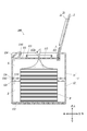
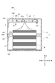
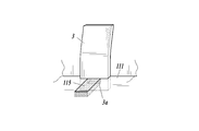
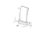
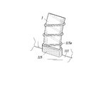
- FIG. 1 It is a perspective view which shows the household thin paper storage container of this embodiment. It is sectional drawing which shows the household thin paper storage container of this embodiment, and is sectional drawing in the Y direction center part of FIG. It is sectional drawing of the household thin paper storage container in the state which closed the opening/closing lid. It is sectional drawing of the household thin paper storage container in the state which unfastened the container main body upper part and the container main body lower part. It is explanatory drawing which expands and shows the fixing part and biasing means of a household thin paper storage container. It is explanatory drawing which expands and shows the fixing part and biasing means of a household thin paper storage container. It is explanatory drawing regarding the modification of the fixing part of the household thin paper storage container. It is explanatory drawing regarding the modification of the fixing part of the household thin paper storage container. It is explanatory drawing regarding the modification of the fixing part of the household thin paper storage container. It is sectional drawing which shows the modification of the fixing part of the household thin paper storage container. It is sectional drawing
- the side of the household thin paper storage container 100 provided with the opening/closing lid 2 is “upper”, the opposite side is “lower”, the side where the container body 1 and the opening/closing lid 2 are connected is “rear”,
- the opposite side is "front”
- the right-hand side in the front view of the container is “right”
- the left-hand side in the front view of the container is “left”
- the axis along the front-rear direction is the X-axis.
- the axis along the horizontal direction is the Y axis
- the axis along the vertical direction is the Z axis.
- the household thin paper sheet storage container 100 includes a container body 1 having an extraction hole 112a through which the domestic thin paper sheet is taken out, and a container body 1 which can be opened and closed so as to cover the extraction hole 112a.
- a storage space S for storing household thin paper P is formed inside the container body 1 by including an open/close lid 2 connected to the open/close lid and a biasing means 3 for biasing the open/close lid 2 in the opening direction.
- the container body 1 and the opening/closing lid 2 can be integrally formed by injection molding (two-color molding).
- ⁇ Household thin paper As the household thin paper P, for example, small wet sheets, wet tissues, etc. are laminated in a state of being alternately folded, and when one wet sheet, wet tissue, etc. is pulled out, the next wet sheet, wet tissue, etc. A so-called pop-up type sheet, which is formed so as to pull out the same, is used. In addition, for example, it is possible to use a long wet sheet that is perforated at regular intervals in the lengthwise direction, a wet tissue, etc., which is wound in a roll shape and is cut along the perforation and used. it can.
- the container body 1 is formed in a generally rectangular parallelepiped shape that is longer in the Y direction than in the X direction and the Z direction, and is divided into upper and lower parts in the vicinity of the substantially central portion in the Z direction.
- An upper part 11 of the container body that constitutes the upper side of the container body 1 and a lower part 12 of the container body that constitutes the lower side of the container body 1 are formed.
- the container body upper part 11 and the container body lower part 12 are connected to each other on the rear side of the container body 1.
- the container body upper part 11 and the container body lower part 12 can be integrally formed by injection molding (two-color molding).
- the container body 1 as a whole is preferably 60 mm to 150 mm in the X direction, more preferably 80 mm to 100 mm, preferably 80 mm to 200 mm in the Y direction, more preferably 145 mm to 165 mm, and preferably 30 mm to 100 mm in the Z direction. It is preferably formed to have a size of 50 mm to 70 mm.
- the thickness of each surface is preferably 0.5 mm to 3 mm, more preferably 1 mm to 2 mm. With this size and thickness, it is possible to achieve high molding efficiency and sufficient strength for practical use.
- the container body 1 has a rear side where the container body upper portion 11 and the container body lower portion 12 are connected as a fulcrum, and the container body upper portion 11 is rotated upward so that an internal storage space is formed. S can be opened to the outside.
- the connecting portion on the rear side of the container body 1 between the container body upper portion 11 and the container body lower portion 12 is formed to be thinner than other portions of the container body 1. By doing so, the rear surface of the container body can be easily bent at the connection portion, and the container body upper portion 11 can be easily rotated with respect to the container body lower portion 12 with the connection portion as a fulcrum.
- the upper part 11 of the container body and the lower part 12 of the container body are separate bodies, and to rotatably connect them by a hinge or the like, although the productivity is reduced.
- the position where the container body 1 is divided into the container body upper part 11 and the container body lower part 12 is shown near the center in the Z direction in the figure, but if it is above the center in the Z direction, , And more preferably.
- the end seal part of the package may be caught when the container is closed. It is possible to reduce the amount, and it becomes easier to refill the household thin paper P.
- the upper part 11 of the container main body is formed into a substantially rectangular parallelepiped shape having an opening on the lower surface, and a concave part 111 is formed on the upper part so as to be downwardly concave.
- a take-out portion 112 on the center side of the recess 111 is provided with a take-out hole 112a for taking out the household thin paper P in the storage space S, and a main body side closed ring portion 113 is formed so as to surround the take-out hole 112a.
- the portion surrounded by the main body side closed ring portion 113 in the recess 111 is formed as the take-out portion 112, and the take-out hole 112a is provided in the central portion of the take-out portion 112.
- a fixed portion 115 is provided in the recess 111 outside the main body side closed ring portion 113 and between the main body side closed ring portion 113 and the opening/closing lid 2, and the fixed portion 115 will be described later.
- Urging means 3 is provided. One end of the biasing means 3 is arranged so as to be embedded in the recess 111.
- locking means 114 for opening and closing the opening/closing lid 2 is formed on the front side of the upper surface.
- an upper fitting portion 116 that fits with a lower fitting portion 121 of the container body lower portion 12 described below is formed around the opening on the lower surface.
- the take-out hole 112 is a hole portion that is formed substantially in the center of the upper surface of the upper part of the container body and that connects to the storage space S.
- FIG. 1 illustrates the case where the cross shape is formed by making two notches, the present invention is not limited to this, and the number of notches may be larger than this, and, for example, the center of gravity of a right triangle may be used. It is also possible to form three notches so as to connect the apex with each of the vertices.
- the take-out hole 112a is made of a material having elasticity around it, and by applying an appropriate resistance to the household thin paper P, the household thin paper P stored in the storage space S is After being pulled out, it fulfills the function of holding the next household thin paper P. Further, when the household thin paper P is a roll sheet, it is possible to cut the household thin paper P with the perforations for cutting provided on the household thin paper P.
- the main body side closed ring portion 113 is a convex portion that protrudes upward in an annular shape so as to surround the extraction hole 112a, and as shown in FIGS. It is formed so as to be fitted to the inner peripheral surface of the opening/closing lid side closed ring portion 22 formed on the opening/closing lid 2 described later.
- the locking means 114 is formed in a button shape having a main body side claw portion 1141, and the main body side claw portion 1141 engages with an opening/closing lid side claw portion 21 formed on an opening/closing lid 2 described later. By doing so, it is locked in the closed state, and when the user presses the locking means 114, the engagement between the main body side claw portion 1141 and the opening/closing lid side claw portion 21 is released, and the opening/closing lid 2 Are formed so as to be in an open state.
- the fixing portion 115 is a portion formed to be substantially flush with the upper surface of the concave portion 111, and is formed to hold the biasing means 3 described later.
- the upper fitting portion 116 is formed around the opening in the lower portion of the container body upper portion 11 except for the rear side where the container body upper portion 11 and the container body lower portion 12 are connected.
- the lower end portion protrudes only on the outer peripheral side to form an upper protruding portion 1161, and an inner peripheral surface of the upper protruding portion 1161 is formed on the lower portion 12 of the container body described later.
- the lower fitting portion 121 is formed so as to fit with the outer peripheral surface of the lower protruding portion 1211.
- the upper fitting portion 116 is formed so that the upper protruding portion 1161 has a length of preferably 0.5 mm to 5 mm, more preferably 1 mm to 3 mm in the vertical direction.
- the take-out portion 112, the body-side closed ring portion 113, and the fixing portion 115 on the upper surface have elasticity such as thermoplastic elastomer such as styrene-butadiene type, polyester type, polyethylene type, urethane type, etc. It is formed of a material that has (hereinafter, referred to as “elastic material”).
- the elastic material preferably has a hardness of 20 to 90. The hardness is measured by JIS K 6253 (type A durometer).
- the upper fitting portion 116 of the container body upper portion 11 is also made of the same elastic material.
- the other part of the upper part 11 of the container body is formed of, for example, a polyolefin resin material such as polyethylene or polypropylene. These are integrally formed by injection molding (two-color molding). If the hardness of the elastic material is lower than the above, it is too soft and difficult to mold, resulting in poor molding efficiency. Further, if the hardness is higher than the above, the area around the ejection hole 112a becomes harder and resistance is applied too much, so that it becomes difficult to take out the sheets one by one, and it becomes difficult to put a finger inside the container when pulling out the sheets. Therefore, the hardness of the elastic material is preferably within the above range.
- the lower part 12 of the container main body is formed in a substantially rectangular parallelepiped shape having an opening on the upper surface, and the upper fitting part 116 of the upper part 11 of the container main body is formed around the opening on the upper surface.
- the lower fitting part 121 which fits is formed.
- a lower anti-slip portion 122 is formed on the lower surface.
- the lower fitting part 121 is formed around the opening in the upper part of the lower container body 12 except for the rear side where the lower container body 12 and the upper container body 11 are connected.
- the upper end protrudes only on the inner peripheral side to form a lower protruding portion 1211, and the outer peripheral surface of the lower protruding portion 1211 is an upper portion formed on the container body upper portion 11. It is formed so as to be fitted to the inner peripheral surface of the upper protruding portion 1161 of the fitting portion 116.
- the lower fitting portion 121 is formed such that the lower protruding portion 1211 has a length in the vertical direction of preferably 0.5 mm to 5 mm, more preferably 1 mm to 3 mm.
- the upper protrusion 1161 of the upper fitting portion 116 is formed so as to protrude only on the inner peripheral side
- the lower protrusion 1211 of the lower fitting portion 121 is formed so as to protrude only on the outer peripheral side.
- the outer peripheral surface of 1161 and the inner peripheral surface of the lower protrusion 1211 may be fitted together.
- the upper protrusion is formed so that the central portion between the inner peripheral side and the outer peripheral side protrudes, and the lower protrusion protrudes on both the inner peripheral side and the outer peripheral side, and a concave portion is formed between them.
- the upper protrusion and the recess between the lower protrusions may be fitted together.
- the upper protrusion is formed so as to protrude on both the inner peripheral side and the outer peripheral side, and a recess is formed therebetween, and the lower protrusion is formed so that the central portion between the inner peripheral side and the outer peripheral side protrudes. It may be formed so that the lower protrusion and the recess between the upper protrusions fit together.
- the lower anti-slip part 122 is a part for making it difficult to slip when the household thin paper storage container 100 is placed, and a part formed of an elastic material is provided on the lower surface of the lower part 12 of the container body. It is formed by being integrally provided with.
- the lower fitting part 121 and the lower anti-slip part 122 are formed of the same elastic material as that used in the upper part 11 of the container body, and the other parts are made of, for example, a polyolefin-based material such as polyethylene or polypropylene. It is made of a resin material. These are integrally formed by injection molding (two-color molding).
- the opening/closing lid 2 is a flat, substantially rectangular member rotatably connected to the rear of the concave portion 111 of the container body upper portion 11, and has the opening/closing lid side claw portion 21 on the front side.
- An opening/closing lid side sealing ring portion 22 is provided on the lower surface side.
- the opening/closing lid 2 is formed such that the shape in plan view when closed is substantially the same as the shape of the recess 111 of the upper part 11 of the container body in plan view. It is formed so that it can be fitted into the recess 111. As shown in FIG.
- the connecting portion between the opening/closing lid 2 and the container body upper portion 11 is formed thinner than other portions, so that the connecting portion can be easily bent. Therefore, the opening/closing lid 2 can be easily rotated about the connecting portion as a fulcrum.
- the opening/closing lid side claw portion 21 is a claw portion that protrudes toward the front of the opening/closing lid 2, and includes a main body side claw portion 1141 formed on the locking means 114 of the container main body upper portion 11.
- the opening/closing lid is locked in the closed state, and when the user presses the locking means 114, the engagement between the main body side claw portion 1141 and the opening/closing lid side claw portion 21 is released,
- the opening/closing lid 2 is formed to be in an open state by a biasing means 3 described later.
- the opening/closing lid side closed ring portion 22 is a convex portion that is formed in the central portion of the lower surface side when the opening/closing lid 2 is closed and that projects downward in an annular shape.
- the surface on the inner peripheral side is formed so as to fit with the surface on the outer peripheral side of the main body side closed ring portion 113 formed in the container main body upper portion 11.
- the opening/closing lid 2 is formed of, for example, a polyolefin resin material such as polyethylene or polypropylene.
- the opening/closing lid 2 and the container body 1 are integrally formed by injection molding (two-color molding).
- the urging means 3 urges the opening/closing lid 2 in the opening direction, and when the user presses the locking means 114, the main body side claw portion 1141 and the opening/closing lid side claw portion 21 are disengaged.
- it is a member for opening the opening/closing lid 2 by rotating the opening/closing lid 2 around the connecting portion with the rear upper part 11 of the container body as a rotation axis.
- the urging means 3 is a leaf spring-like member made of a thermosetting resin material such as an elastic silicone resin (silicon rubber). As shown in FIG. 5A, a small hole 3a is provided at one end of the biasing means 3, and the fixing portion 115 is inserted into the small hole 3a. Specifically, when the opening/closing lid 2 and the container body 1 are integrally formed by injection molding (two-color molding), the small holes 3a of the urging means 3 formed of a thermosetting resin material in advance are used. The elastic material to be the fixing portion 115 is injected so as to be driven in, and the biasing means 3 is fixed to the formed fixing portion 115 to be embedded in the concave portion 111.
- a thermosetting resin material such as an elastic silicone resin (silicon rubber).
- the biasing means 3 is fixed to the fixed portion 115 in a state where the fixed portion 115 is formed by injection molding.
- the fixing portion 115 is injection-molded with the elastic material
- the biasing means 3 previously formed with the thermosetting resin material is fixed to the fixing portion 115.
- the step of fixing is included. It should be noted that the biasing means 3 fixed to the fixing portion 115 cannot be removed from the container body 1 (fixing portion 115) when the fixing portion 115 is formed on a part of the container main body 1 formed by injection molding. It is fixed in the state.
- the household thin paper storage container 100 can be produced by forming the container body 1, the opening/closing lid 2, and the biasing means 3 by pseudo three-color molding. If the biasing means 3 is fixed to the injection-molded fixing portion 115, the household thin paper storage container 100 can be manufactured with high productivity. Note that, as shown in FIG. 5B, the biasing means 3 having the notch 3b at one end thereof can be similarly formed in a manner in which the biasing means 3 is fixed to the injection-molded fixing portion 115. ..
- the biasing means 3 is formed to have a band shape having a width of preferably 5 mm to 30 mm, more preferably 8 mm to 15 mm, and a thickness of preferably 0.5 mm to 3 mm, further preferably 1 mm to 2 mm. Since the urging means 3 is formed in such a size, the opening/closing lid 2 can be pushed up without difficulty, and when the opening/closing lid 2 is closed, the urging means 3 can be moved in the recess 111. Can be easily folded.
- the biasing means 3 is bent near the base of the opening/closing lid 2 when the opening/closing lid 2 is closed. Then, when the user presses the locking means 114 and the main body side claw portion 1141 is disengaged from the opening/closing lid side claw portion 21, the biasing means 3 that has been bent tries to restore.
- the opening/closing lid 2 is opened by the repulsive force, and the state shown in FIG. 2 is obtained. Further, when the user closes the opening/closing lid 2, if the opening/closing lid is pushed from above, the urging means 3 is bent and the state shown in FIG. 3 is obtained.
- the opening/closing lid 2 when the user operates the locking means 114 and the locking of the opening/closing lid 2 is released, the opening/closing lid 2 is automatically flipped up by the biasing means 3. Therefore, the opening/closing lid can be easily opened when using household thin paper.
- the urging means 3 is formed of a thermosetting resin material such as a silicone rubber resin, not a thermoplastic elastomer or a thermoplastic resin material, it does not easily deteriorate over time, and the opening/closing lid 2 is attached in the opening direction. Since the function as a biasing spring can be maintained, this household thin paper storage container 100 can be used for a long period of time.
- this household thin paper storage container 100 is manufactured so that the biasing means 3 is fixed to the fixing portion 115 when the container body 1 and the opening/closing lid 2 are integrally formed by injection molding (two-color molding). Since the container body 1, the opening/closing lid 2 and the biasing means 3 can be produced by forming the pseudo three-color molding, the biasing means 3 formed in advance by a thermosetting resin material can be manufactured. The use of does not reduce the productivity.
- the take-out portion 112 provided with the take-out hole 112a is made of an elastic material, it is possible to apply an appropriate resistance to the household thin paper P pulled out from the take-out hole 112a, and the storage space S After the housed thin paper P for housed is pulled out, the next household thin paper P can be suitably held.
- the household thin paper P is a roll sheet, the household thin paper P can be suitably cut with the perforations for cutting provided on the household thin paper P.
- the container body 1 is composed of the container body upper portion 11 and the container body lower portion 12, and these are connected at the rear surface, so that the container body 1 can be opened at its central portion and stored in the storage space S inside.
- the household thin paper P can be refilled. Therefore, at the time of refilling the household thin paper P, it is not necessary to lift the household thin paper storage container 100, and the refilling work can be performed while being placed on the table or the like.
- the container body upper part 11 and the container body lower part 12 are connected to each other on the rear surface, and the container body upper part 11 is rotated with respect to the container body lower part 12 by using the connection portion as a fulcrum to store the storage space. S can be opened and closed. Therefore, after refilling, etc., the container main body upper part 11 and the container main body lower part 12 can be easily fitted to each other to bring the container main body into a closed state without aligning the positions one by one. The trouble of refilling P can be reduced.
- the upper fitting portion 116 is formed of the elastic material on the container body upper portion 11, and the lower fitting portion 121 is formed of the elastic material on the container body lower portion 12.
- the lower non-slip portion 122 is formed of the elastic material on the lower surface of the container body 1, it is possible to improve the stability when the container body 1 is placed on a table or the like.
- an elastic material serving as the fixing portion 115 is injected so as to wrap around the lower end of the biasing means 3 formed of a thermosetting resin material, and the biasing means is formed by the molded fixing portion 115. 3 may be held.
- a linear portion 115 a that is a part of the fixed portion 115 that covers and holds the lower end portion of the biasing means 3 is arranged along the circumferential surface of the biasing means 3.
- the linear portion 115a forming a part of the fixed portion 115 can be formed by injection molding an elastic material together with the fixed portion 115.
- a coil spring-shaped linear portion 115a that spirally extends along the peripheral surface of the biasing means 3 is illustrated. In this way, the repulsive force of the urging means 3 can be adjusted by arranging part of the fixing portion 115 along the peripheral surface of the urging means 3.
- the fixing portion 115 is formed integrally with the take-out portion 112 and the main body side sealing ring portion 113 by an elastic material, but the present invention is not limited to this.
- the fixing portion 115 may be integrally formed with the opening/closing lid 2 and the like by a polyolefin resin material such as polyethylene or polypropylene.
- the fixing portion 115 for fixing the biasing means 3 to the household thin paper storage container 100 may be provided in the opening/closing lid 2. That is, in a state where the fixing portion 115 is formed on a part of the opening/closing lid 2 formed by injection molding, the biasing means 3 fixed to the fixing portion 115 cannot be removed from the opening/closing lid 2 (fixing portion 115). It is fixed in the state.
- the container body 1, the opening/closing lid 2, and the urging means 3 are formed by pseudo three-color molding so that the urging means 3 is fixed to the opening/closing lid 2 side, and the household thin paper storage container 100 is formed. Can be produced. If the biasing means 3 is fixed to the fixed portion 115 that is injection-molded together with the opening/closing lid 2, the household thin paper storage container 100 can be manufactured with high productivity.
- the container body 1 and the opening/closing lid 2 are integrally formed by injection molding (two-color molding), but the present invention is not limited to this, and the productivity is reduced.
- the container body 1 and the opening/closing lid 2 are also possible to form the container body 1 and the opening/closing lid 2 as separate bodies, and connect them rotatably by a hinge or the like.
- the opening/closing lid 2 integrally formed with the container body 1 by injection molding is formed of a polyolefin resin material such as polyethylene or polypropylene.
- the present invention is not limited to this, and the opening/closing lid 2 integrally formed with the container body 1 by injection molding (two-color molding) may be partially or entirely formed of an elastic material.
- the present invention is configured as described above, it can be used as a household thin paper storage container that can be opened with the opening/closing lid suitably.
Landscapes
- Engineering & Computer Science (AREA)
- Mechanical Engineering (AREA)
- Health & Medical Sciences (AREA)
- Public Health (AREA)
- Closures For Containers (AREA)
- Containers And Packaging Bodies Having A Special Means To Remove Contents (AREA)
Abstract
この家庭用薄葉紙収納容器100であれば、使用者が係止手段114を操作して開閉蓋2の係止が外れると、付勢手段3によって開閉蓋2が自動的に跳ね上げられるので、家庭用薄葉紙使用時の開閉蓋の開放が容易となる。特に、この付勢手段3は、熱可塑性エラストマーや熱可塑性樹脂材料ではなく、シリコンゴム樹脂など熱硬化性樹脂材料によって形成されたものであるため経年劣化し難く、開閉蓋2を開放方向に付勢するバネとしての機能を維持できるので、この家庭用薄葉紙収納容器100を長期間に亘って使い続けることができる。
Description
本発明は、家庭用薄葉紙収納容器に関する。
従来、ウェットティッシュ等の家庭用薄葉紙の収納容器としては、開閉蓋を板バネ等の付勢部材によって開放方向に付勢しつつ、これを所定の係止部材によって閉塞状態で係止可能とすることで、使用者が係止部材に設けられたボタンを押圧した際に、ワンタッチで開閉蓋が開くようにしたものが知られている(例えば、特許文献1参照。)。
家庭用薄葉紙の収納容器は詰め替え式であり、家庭用薄葉紙を使い切った際には新たな家庭用薄葉紙を収納して、その収納容器を長期間使い続けるようになっている。
家庭用薄葉紙の収納容器は詰め替え式であり、家庭用薄葉紙を使い切った際には新たな家庭用薄葉紙を収納して、その収納容器を長期間使い続けるようになっている。
しかしながら、上記特許文献1の収納容器の板バネ(付勢手段)が熱可塑性樹脂で形成されている場合、長期間使い続けるうちに経年劣化し、バネとしての機能が低下して蓋が開き難くなってしまうことがあった。
本発明の目的は、開閉蓋を好適に開放できる家庭用薄葉紙収納容器を提供することである。
以上の課題を解決するため、請求項1に記載の発明は、
内部に家庭用薄葉紙が収納され、その家庭用薄葉紙を取り出す取出孔を有する容器本体と、
前記容器本体に回動自在に取り付けられ、前記取出孔を閉塞する開閉蓋と、
前記開閉蓋を開放方向に付勢する付勢手段と、
を備えた家庭用薄葉紙収納容器であって、
前記容器本体は、前記開閉蓋を閉塞状態で係止するとともに、これを解除して前記開閉蓋を開放させることができる係止手段と、前記付勢手段を当該容器本体に固定している固定部と、を備えており、
前記付勢手段は、熱硬化性樹脂材料によって形成されている部材であり、
前記固定部が前記容器本体の一部に形成された状態で、その固定部に前記付勢手段が固定されているように構成されていることを特徴とする。
熱硬化性樹脂材料によって形成された付勢手段であれば経年劣化し難く、開閉蓋を開放方向に付勢するバネとしての機能を維持できるので、開閉蓋を好適に開放できる家庭用薄葉紙収納容器として長期間に亘って使い続けることができる。
請求項2に記載の発明は、
内部に家庭用薄葉紙が収納され、その家庭用薄葉紙を取り出す取出孔を有する容器本体と、
前記容器本体に回動自在に取り付けられ、前記取出孔を閉塞する開閉蓋と、
前記開閉蓋を開放方向に付勢する付勢手段と、
を備えた家庭用薄葉紙収納容器であって、
前記容器本体は、前記開閉蓋を閉塞状態で係止するとともに、これを解除して前記開閉蓋を開放させることができる係止手段を備えており、
前記開閉蓋は、前記付勢手段を当該開閉蓋に固定している固定部を備えており、
前記付勢手段は、熱硬化性樹脂材料によって形成されている部材であり、
前記固定部が前記開閉蓋の一部に形成された状態で、その固定部に前記付勢手段が固定されているように構成されていることを特徴とする。
熱硬化性樹脂材料によって形成された付勢手段であれば経年劣化し難く、開閉蓋を開放方向に付勢するバネとしての機能を維持できるので、開閉蓋を好適に開放できる家庭用薄葉紙収納容器として長期間に亘って使い続けることができる。
請求項3に記載の発明は、請求項1又は2に記載の家庭用薄葉紙収納容器において、
前記固定部は、前記付勢手段に設けられている小孔または切欠に差し込まれた状態に形成されていることを特徴とする。
前記固定部は、前記付勢手段に設けられている小孔または切欠に差し込まれた状態に形成されていることを特徴とする。
請求項4に記載の発明は、請求項1又は2に記載の家庭用薄葉紙収納容器において、
前記固定部は、前記付勢手段の端部を覆って保持した状態に形成されていることを特徴とする。
前記固定部は、前記付勢手段の端部を覆って保持した状態に形成されていることを特徴とする。
請求項5に記載の発明は、請求項1~4のいずれか一項に記載の家庭用薄葉紙収納容器において、
前記固定部の一部が、前記付勢手段の周面に沿わして配されていることを特徴とする。
前記固定部の一部が、前記付勢手段の周面に沿わして配されていることを特徴とする。
本発明によれば、開閉蓋を好適に開放できる家庭用薄葉紙収納容器が得られる。
以下、図面を参照して、本発明に係る家庭用薄葉紙収納容器の実施形態について詳細に説明する。但し、以下に述べる実施形態には、本発明を実施するために技術的に好ましい種々の限定が付されているが、本発明の範囲を以下の実施形態及び図示例に限定するものではない。
なお、以下においては、図1に示すように、X軸、Y軸及びZ軸並びに前後方向、左右方向及び上下方向を定めて説明する。すなわち、家庭用薄葉紙収納容器100の開閉蓋2が備えられた側を「上」、その反対側を「下」、容器本体1と開閉蓋2とが接続されている側を「後」、その反対側を「前」、容器の前面を正面視した状態における右手側を「右」、容器の前面を正面視した状態における左手側を「左」とし、前後方向に沿った軸をX軸、左右方向に沿った軸をY軸、上下方向の沿った軸をZ軸とする。
なお、以下においては、図1に示すように、X軸、Y軸及びZ軸並びに前後方向、左右方向及び上下方向を定めて説明する。すなわち、家庭用薄葉紙収納容器100の開閉蓋2が備えられた側を「上」、その反対側を「下」、容器本体1と開閉蓋2とが接続されている側を「後」、その反対側を「前」、容器の前面を正面視した状態における右手側を「右」、容器の前面を正面視した状態における左手側を「左」とし、前後方向に沿った軸をX軸、左右方向に沿った軸をY軸、上下方向の沿った軸をZ軸とする。
[実施形態の構成]
{全体構成}
家庭用薄葉紙収納容器100は、例えば、図1~図4に示すように、内部の家庭用薄葉紙を取り出す取出孔112aを有する容器本体1と、取出孔112aを覆うように開閉自在に容器本体1に接続された開閉蓋2と、開閉蓋2を開放方向に付勢する付勢手段3とを備え、容器本体1の内部に家庭用薄葉紙Pが収納される収納空間Sが形成されている。
容器本体1と、開閉蓋2とは、射出成形(2色成形)によって一体的に形成することができる。
{全体構成}
家庭用薄葉紙収納容器100は、例えば、図1~図4に示すように、内部の家庭用薄葉紙を取り出す取出孔112aを有する容器本体1と、取出孔112aを覆うように開閉自在に容器本体1に接続された開閉蓋2と、開閉蓋2を開放方向に付勢する付勢手段3とを備え、容器本体1の内部に家庭用薄葉紙Pが収納される収納空間Sが形成されている。
容器本体1と、開閉蓋2とは、射出成形(2色成形)によって一体的に形成することができる。
{家庭用薄葉紙}
家庭用薄葉紙Pとしては、例えば、小型のウェットシート、ウェットティッシュ等が交互に折り重ねられた状態で積層され、1枚のウェットシート、ウェットティッシュ等を引き出した際に次のウェットシート、ウェットティッシュ等も引き出されるように形成された、所謂ポップアップ式のシートが用いられる。その他には、例えば、長さ方向に一定の間隔でミシン目が施された長大なウェットシート、ウェットティッシュ等がロール状に巻かれ、ミシン目に沿って切り離して使用するロールシートを用いることもできる。
家庭用薄葉紙Pとしては、例えば、小型のウェットシート、ウェットティッシュ等が交互に折り重ねられた状態で積層され、1枚のウェットシート、ウェットティッシュ等を引き出した際に次のウェットシート、ウェットティッシュ等も引き出されるように形成された、所謂ポップアップ式のシートが用いられる。その他には、例えば、長さ方向に一定の間隔でミシン目が施された長大なウェットシート、ウェットティッシュ等がロール状に巻かれ、ミシン目に沿って切り離して使用するロールシートを用いることもできる。
{容器本体}
容器本体1は、図1に示すように、全体として、X方向及びZ方向に比してY方向に長い略直方体状に形成され、これがZ方向略中央部付近において上下に二分され、容器本体1の上側を構成する容器本体上部11と、容器本体1の下側を構成する容器本体下部12と、が形成されている。容器本体上部11と、容器本体下部12とは容器本体1の後側において接続されている。
容器本体上部11と、容器本体下部12とは、射出成形(2色成形)によって一体的に形成することができる。
容器本体1は、図1に示すように、全体として、X方向及びZ方向に比してY方向に長い略直方体状に形成され、これがZ方向略中央部付近において上下に二分され、容器本体1の上側を構成する容器本体上部11と、容器本体1の下側を構成する容器本体下部12と、が形成されている。容器本体上部11と、容器本体下部12とは容器本体1の後側において接続されている。
容器本体上部11と、容器本体下部12とは、射出成形(2色成形)によって一体的に形成することができる。
容器本体1は、全体が、X方向に好ましくは60mmから150mm、さらに好ましくは80mmから100mm、Y方向に好ましくは80mmから200mm、さらに好ましくは145mmから165mm、Z方向に好ましくは30mmから100mm、さらに好ましくは50mmから70mmの大きさとなるように形成されている。また、各面の厚みは、好ましくは0.5mmから3mm、さらに好ましくは1mmから2mmである。
この大きさ及び厚みであれば、成形効率が高く、かつ実使用に問題ない強度を達成することができる。
この大きさ及び厚みであれば、成形効率が高く、かつ実使用に問題ない強度を達成することができる。
容器本体1は、図4に示すように、容器本体上部11と容器本体下部12とが接続された後側を支点とし、容器本体上部11を上方へと回動させることによって、内部の収納空間Sを外部に開放することができる。
容器本体1後側の、容器本体上部11と容器本体下部12との接続部分が、図2~図4に示すように、容器本体1の他の部分と比較して薄くなるように形成されていることによって、当該接続部分において容器本体の後面を容易に曲げることができ、容器本体上部11を、当該接続部分を支点として、容器本体下部12に対して回動させ易くなる。
容器本体1後側の、容器本体上部11と容器本体下部12との接続部分が、図2~図4に示すように、容器本体1の他の部分と比較して薄くなるように形成されていることによって、当該接続部分において容器本体の後面を容易に曲げることができ、容器本体上部11を、当該接続部分を支点として、容器本体下部12に対して回動させ易くなる。
なお、生産性は低下するものの、容器本体上部11と、容器本体下部12とを別体として形成の上、これらをヒンジ等によって回動自在に接続することも可能である。
また、容器本体1が容器本体上部11と容器本体下部12とに二分される位置は、図においては、Z方向中央部付近とした場合につき図示したが、Z方向中央部よりも上部であれば、さらに好ましい。この場合、収納された家庭用薄葉紙Pが所定の包装体によって覆われた状態で、容器本体1内に収納される場合において、容器の閉塞時に包装体のエンドシール部等を挟み込んでしまうおそれを低減することができ、家庭用薄葉紙Pをさらに詰め替え易くなる。
また、容器本体1が容器本体上部11と容器本体下部12とに二分される位置は、図においては、Z方向中央部付近とした場合につき図示したが、Z方向中央部よりも上部であれば、さらに好ましい。この場合、収納された家庭用薄葉紙Pが所定の包装体によって覆われた状態で、容器本体1内に収納される場合において、容器の閉塞時に包装体のエンドシール部等を挟み込んでしまうおそれを低減することができ、家庭用薄葉紙Pをさらに詰め替え易くなる。
(容器本体上部)
容器本体上部11は、図1~図4に示すように、下面が開口部となった略直方体状に形成され、上部に下方に凹状となる凹部111が形成されている。
その凹部111の中央側の取出し部112には、収納空間Sの家庭用薄葉紙Pを取り出す取出孔112aが設けられ、取出孔112aを囲むようにして、本体側密閉環部113が形成されている。換言すれば、凹部111内における本体側密閉環部113に囲まれた部分が取出し部112として形成されており、取出し部112の中央部に取出孔112aが設けられている。
また、凹部111内における本体側密閉環部113よりも外側の部分であって、本体側密閉環部113と開閉蓋2の間には固定部115が設けられており、その固定部115に後述の付勢手段3が配設されている。その付勢手段3の一端部は凹部111に埋め込まれた態様に配設されている。
また、上面の前側には、開閉蓋2を開閉するための係止手段114が形成されている。
また、下面の開口部の周囲には、後述の容器本体下部12の下部嵌合部121と嵌合する上部嵌合部116が形成されている。
(取出孔)
取出孔112は、容器本体上部の上面略中央に形成された、収納空間Sにつながる孔部である。
図1においては、十字型に2本の切り込みを入れることにより形成されている場合につき図示したが、これに限られず、切り込みの本数はこれより多数でもよく、また、例えば、直角三角形の重心点と各頂点とを結ぶように、3本の切り込みを形成するようにしてもよい。
この取出孔112aは、後述するようにその周囲が弾性を有する材料によって形成されており、家庭用薄葉紙Pに対して適切な抵抗を掛けることで、収納空間Sに収納された家庭用薄葉紙Pが引き出された後に、次の家庭用薄葉紙Pを保持する機能を果たす。また、家庭用薄葉紙Pがロールシートである場合において、家庭用薄葉紙Pに設けられている切断用のミシン目で、これを切断することを可能とする。
(本体側密閉環部)
本体側密閉環部113は、図1に示すように、取出孔112aを囲むように環状に上方へと突出する凸部であり、図3及び図4に示すように、その外周側の面が後述の開閉蓋2に形成された開閉蓋側密閉環部22の内周側の面と嵌合するように形成されている。
本体側密閉環部113は、図1に示すように、取出孔112aを囲むように環状に上方へと突出する凸部であり、図3及び図4に示すように、その外周側の面が後述の開閉蓋2に形成された開閉蓋側密閉環部22の内周側の面と嵌合するように形成されている。
(係止手段)
係止手段114は、図1に示すように、本体側爪部1141を備えるボタン状に形成され、本体側爪部1141が後述の開閉蓋2に形成される開閉蓋側爪部21と係合することによって、これを閉塞状態で係止するとともに、使用者が係止手段114を押圧した際には、本体側爪部1141と開閉蓋側爪部21との係合が外れ、開閉蓋2が開放状態となるように形成されている。
係止手段114は、図1に示すように、本体側爪部1141を備えるボタン状に形成され、本体側爪部1141が後述の開閉蓋2に形成される開閉蓋側爪部21と係合することによって、これを閉塞状態で係止するとともに、使用者が係止手段114を押圧した際には、本体側爪部1141と開閉蓋側爪部21との係合が外れ、開閉蓋2が開放状態となるように形成されている。
(固定部)
固定部115は、図1、図5Aに示すように、凹部111の上面と略面一に形成された部分であり、後述の付勢手段3を保持するように形成されている。
固定部115は、図1、図5Aに示すように、凹部111の上面と略面一に形成された部分であり、後述の付勢手段3を保持するように形成されている。
(上部嵌合部)
上部嵌合部116は、図1~図4に示すように、容器本体上部11下部の開口部の周囲に、容器本体上部11と容器本体下部12とが接続された後側を除いて形成され、図2~図4に示すように、下端部が外周側のみ突出し、上部突出部1161が形成されており、上部突出部1161の内周側の面が、後述の容器本体下部12に形成される下部嵌合部121の下部突出部1211の外周側の面と嵌合するように形成されている。
上部嵌合部116は、上部突出部1161が、上下方向に好ましくは0.5mmから5mm、さらに好ましくは1mmから3mmの長さを有するように形成される。
上部嵌合部116は、図1~図4に示すように、容器本体上部11下部の開口部の周囲に、容器本体上部11と容器本体下部12とが接続された後側を除いて形成され、図2~図4に示すように、下端部が外周側のみ突出し、上部突出部1161が形成されており、上部突出部1161の内周側の面が、後述の容器本体下部12に形成される下部嵌合部121の下部突出部1211の外周側の面と嵌合するように形成されている。
上部嵌合部116は、上部突出部1161が、上下方向に好ましくは0.5mmから5mm、さらに好ましくは1mmから3mmの長さを有するように形成される。
(容器本体上部の材質)
容器本体上部11のうち、上面の取出し部112と本体側密閉環部113と固定部115とが、例えば、スチレン-ブタジエン系、ポリエステル系、ポリエチレン系、ウレタン系等の熱可塑性エラストマー等の弾性を有する材料(以下、「弾性材料」という。)によって形成されている。弾性材料の性質としては、硬度が20から90であることが望ましい。なお、上記硬度は、JIS K 6253(タイプAデュロメータ)によって測定されたものである。
また、容器本体上部11のうち、上部嵌合部116も、同様の弾性材料によって形成されている。
容器本体上部11のその他の部分は、例えば、ポリエチレン、ポリプロピレン等のポリオレフィン系樹脂材料によって形成されている。
これらは、射出成形(2色成形)によって一体的に形成されている。
なお、弾性材料の硬度が上記よりも低くなると、柔らか過ぎて成形が難しく、成形効率が悪くなる。また、硬度が上記よりも高くなると、取出孔112a周辺が硬くなり、抵抗が掛かり過ぎて、シートが一枚ずつ取り出しにくくなり、かつ、シートを引っ張り出す際に容器内部まで指を入れ難くなる。
したがって、弾性材料の硬度は、上記範囲とすることが望ましい。
(容器本体下部)
容器本体下部12は、図1~図4に示すように、上面が開口部となった略直方体状に形成され、上面の開口部の周囲には、容器本体上部11の上部嵌合部116と嵌合する下部嵌合部121が形成されている。また、下面には、下部滑り止め部122が形成されている。
容器本体下部12は、図1~図4に示すように、上面が開口部となった略直方体状に形成され、上面の開口部の周囲には、容器本体上部11の上部嵌合部116と嵌合する下部嵌合部121が形成されている。また、下面には、下部滑り止め部122が形成されている。
(下部嵌合部)
下部嵌合部121は、図1~図4に示すように、容器本体下部12上部の開口部の周囲に、容器本体下部12と容器本体上部11とが接続された後側を除いて形成され、図2~図4に示すように、上端部が内周側のみ突出し、下部突出部1211が形成されており、下部突出部1211の外周側の面が、容器本体上部11に形成される上部嵌合部116の上部突出部1161の内周側の面と嵌合するように形成されている。
下部嵌合部121は、下部突出部1211が、上下方向に好ましくは0.5mmから5mm、さらに好ましくは1mmから3mmの長さを有するように形成される。
下部嵌合部121は、図1~図4に示すように、容器本体下部12上部の開口部の周囲に、容器本体下部12と容器本体上部11とが接続された後側を除いて形成され、図2~図4に示すように、上端部が内周側のみ突出し、下部突出部1211が形成されており、下部突出部1211の外周側の面が、容器本体上部11に形成される上部嵌合部116の上部突出部1161の内周側の面と嵌合するように形成されている。
下部嵌合部121は、下部突出部1211が、上下方向に好ましくは0.5mmから5mm、さらに好ましくは1mmから3mmの長さを有するように形成される。
なお、上部嵌合部116の上部突出部1161が、内周側のみ突出するように形成され、下部嵌合部121の下部突出部1211が、外周側のみ突出するように形成され、上部突出部1161の外周側の面と、下部突出部1211の内周側の面とが嵌合するようにしてもよい。
また、上部突出部が、内周側と外周側の間の中央部が突出するように形成され、下部突出部が、内周側と外周側の両側において突出し、間に凹部が生じるように形成され、上部突出部と、下部突出部の間の凹部とが嵌合するようにしてもよい。反対に、上部突出部が、内周側と外周側の両側において突出し、間に凹部が生じるように形成され、下部突出部が、内周側と外周側の間の中央部が突出するように形成され、下部突出部と、上部突出部の間の凹部とが嵌合するようにしてもよい。
また、上部突出部が、内周側と外周側の間の中央部が突出するように形成され、下部突出部が、内周側と外周側の両側において突出し、間に凹部が生じるように形成され、上部突出部と、下部突出部の間の凹部とが嵌合するようにしてもよい。反対に、上部突出部が、内周側と外周側の両側において突出し、間に凹部が生じるように形成され、下部突出部が、内周側と外周側の間の中央部が突出するように形成され、下部突出部と、上部突出部の間の凹部とが嵌合するようにしてもよい。
(下部滑り止め部)
下部滑り止め部122は、家庭用薄葉紙収納容器100を載置した際にこれを滑りにくくするための部分であり、容器本体下部12の下面に、弾性材料によって形成された部分を、他の部分と一体的に設けることにより形成されている。
下部滑り止め部122は、家庭用薄葉紙収納容器100を載置した際にこれを滑りにくくするための部分であり、容器本体下部12の下面に、弾性材料によって形成された部分を、他の部分と一体的に設けることにより形成されている。
(容器本体下部の材質)
容器本体下部12は、下部嵌合部121及び下部滑り止め部122が、容器本体上部11において用いられるのと同様の弾性材料によって形成され、その他の部分は、例えば、ポリエチレン、ポリプロピレン等のポリオレフィン系樹脂材料によって形成されている。
これらは、射出成形(2色成形)によって一体的に形成されている。
容器本体下部12は、下部嵌合部121及び下部滑り止め部122が、容器本体上部11において用いられるのと同様の弾性材料によって形成され、その他の部分は、例えば、ポリエチレン、ポリプロピレン等のポリオレフィン系樹脂材料によって形成されている。
これらは、射出成形(2色成形)によって一体的に形成されている。
{開閉蓋}
開閉蓋2は、図1~図4に示すように、容器本体上部11の凹部111後方に回動自在に接続された扁平な略矩形状の部材であり、前側に開閉蓋側爪部21を備え、下面側に開閉蓋側密閉環部22を備える。
開閉蓋2は、図1~図4に示すように、閉塞時の平面視における形状が容器本体上部11の凹部111の平面視における形状と略同一となるように形成されており、閉塞時において、凹部111に嵌め込むことができるように形成されている。
なお、開閉蓋2と容器本体上部11との接続部分が、図2に示すように、他の部分と比較して薄くなるように形成されていることによって、当該接続部分を容易に曲げることができ、開閉蓋2を、当該接続部分を支点として回動させ易くなる。
(開閉蓋側爪部)
開閉蓋側爪部21は、図1~図4に示すように、開閉蓋2の前方に突出する爪部であり、容器本体上部11の係止手段114に形成される本体側爪部1141と係合することによって、開閉蓋を閉塞状態で係止するとともに、使用者が係止手段114を押圧した際には、本体側爪部1141と開閉蓋側爪部21との係合が外れ、後述の付勢手段3によって、開閉蓋2が開放状態となるように形成されている。
開閉蓋側爪部21は、図1~図4に示すように、開閉蓋2の前方に突出する爪部であり、容器本体上部11の係止手段114に形成される本体側爪部1141と係合することによって、開閉蓋を閉塞状態で係止するとともに、使用者が係止手段114を押圧した際には、本体側爪部1141と開閉蓋側爪部21との係合が外れ、後述の付勢手段3によって、開閉蓋2が開放状態となるように形成されている。
(開閉蓋側密閉環部)
開閉蓋側密閉環部22は、図1に示すように、開閉蓋2の閉塞時における下面側中央部に形成された、下方へと環状に突出する凸部であり、図3及び図4に示すように、その内周側の面が、容器本体上部11に形成された本体側密閉環部113の外周側の面と嵌合するように形成されている。
開閉蓋側密閉環部22は、図1に示すように、開閉蓋2の閉塞時における下面側中央部に形成された、下方へと環状に突出する凸部であり、図3及び図4に示すように、その内周側の面が、容器本体上部11に形成された本体側密閉環部113の外周側の面と嵌合するように形成されている。
(開閉蓋の材質)
開閉蓋2は、例えば、ポリエチレン、ポリプロピレン等のポリオレフィン系樹脂材料によって形成されている。
この開閉蓋2と、容器本体1とは、射出成形(2色成形)によって一体的に形成されている。
開閉蓋2は、例えば、ポリエチレン、ポリプロピレン等のポリオレフィン系樹脂材料によって形成されている。
この開閉蓋2と、容器本体1とは、射出成形(2色成形)によって一体的に形成されている。
{付勢手段}
付勢手段3は、開閉蓋2を開放方向へと付勢し、使用者が係止手段114を押圧し、本体側爪部1141と、開閉蓋側爪部21との係合が外れた際に、開閉蓋2を後方の容器本体上部11との接続部分を回転軸として回転するようにして開放させるための部材である。
付勢手段3は、開閉蓋2を開放方向へと付勢し、使用者が係止手段114を押圧し、本体側爪部1141と、開閉蓋側爪部21との係合が外れた際に、開閉蓋2を後方の容器本体上部11との接続部分を回転軸として回転するようにして開放させるための部材である。
付勢手段3は、弾力性を有するシリコン樹脂(シリコンゴム)など熱硬化性樹脂材料によって形成された板バネ状の部材である。
図5Aに示すように、付勢手段3の一端部には小孔3aが設けられており、その小孔3aに固定部115が差し込まれた状態に形成されている。
具体的には、開閉蓋2と容器本体1とを射出成形(2色成形)によって一体的に形成する際に、予め熱硬化性樹脂材料によって形成されている付勢手段3の小孔3aに、固定部115となる弾性材料を打ち込むように射出し、成形された固定部115に付勢手段3が固定されて、凹部111部分に埋め込まれた態様に形成される。
つまり、固定部115部分が射出成形によって形成された状態で、その固定部115に付勢手段3が固定されるようになっている。換言すれば、この家庭用薄葉紙収納容器100の製造工程には、弾性材料によって固定部115を射出成形する際に、予め熱硬化性樹脂材料によって形成されている付勢手段3を固定部115に固定する工程が含まれている。
なお、射出成形によって形成された容器本体1の一部に固定部115が形成された状態で、その固定部115に固定された付勢手段3は、容器本体1(固定部115)から取り外せない状態に固定されている。
このように、容器本体1と開閉蓋2と付勢手段3とを疑似3色成形にて形成するようにして家庭用薄葉紙収納容器100を生産することができる。
射出成形した固定部115に付勢手段3が固定されるようにすれば、生産性よく家庭用薄葉紙収納容器100を製造できる。
なお、図5Bに示すように、その一端部に切欠3bが設けられている付勢手段3であっても同様に、射出成形した固定部115に付勢手段3が固定された態様に形成できる。
付勢手段3は、幅が好ましくは5mm~30mm、さらに好ましくは8mm~15mm、厚みが好ましくは0.5mm~3mm、さらに好ましくは1mm~2mmの帯状となるように形成されている。
付勢手段3がこのような大きさに形成されていることによって、開閉蓋2を無理なく押し上げることが可能であり、かつ、開閉蓋2の閉塞時において、凹部111内において付勢手段3を容易に折り曲げることができる。
付勢手段3がこのような大きさに形成されていることによって、開閉蓋2を無理なく押し上げることが可能であり、かつ、開閉蓋2の閉塞時において、凹部111内において付勢手段3を容易に折り曲げることができる。
付勢手段3は、図3に示すように、開閉蓋2の閉塞時において、これが開閉蓋2の付け根近傍において折り曲げられることとなる。そして、使用者が係止手段114を押圧し、本体側爪部1141と、開閉蓋側爪部21との係合が外れた際には、折り曲げられていた付勢手段3が復元しようとする反発力によって、開閉蓋2が開放され、図2に示す状態となる。
また、使用者が開閉蓋2を閉塞する際には、開閉蓋を上方から押せば、付勢手段3が折り曲げられ、図3に示す状態となる。
また、使用者が開閉蓋2を閉塞する際には、開閉蓋を上方から押せば、付勢手段3が折り曲げられ、図3に示す状態となる。
[実施形態の効果]
本実施形態の家庭用薄葉紙収納容器100によれば、使用者が係止手段114を操作し、開閉蓋2の係止が外れると、付勢手段3によって、開閉蓋2が自動的に跳ね上げられることから、家庭用薄葉紙使用時の開閉蓋の開放が容易となる。
特に、この付勢手段3は、熱可塑性エラストマーや熱可塑性樹脂材料ではなく、シリコンゴム樹脂など熱硬化性樹脂材料によって形成されたものであるため経年劣化し難く、開閉蓋2を開放方向に付勢するバネとしての機能を維持できるので、この家庭用薄葉紙収納容器100を長期間に亘って使い続けることができる。
そして、この家庭用薄葉紙収納容器100は、容器本体1と開閉蓋2とを射出成形(2色成形)によって一体的に形成する際に付勢手段3を固定部115に固定するように生産することができ、容器本体1と開閉蓋2と付勢手段3とを疑似3色成形にて形成するようにして生産することができるので、予め熱硬化性樹脂材料によって形成された付勢手段3を用いることによっても生産性の低下を招くこともない。
また、取出孔112aが設けられている取出し部112は、弾性材料によって形成されているので、取出孔112aから引き出した家庭用薄葉紙Pに対して適切な抵抗を掛けることができ、収納空間Sに収納された家庭用薄葉紙Pが引き出された後に、次の家庭用薄葉紙Pを好適に保持することができる。また、家庭用薄葉紙Pがロールシートである場合、家庭用薄葉紙Pに設けられている切断用のミシン目で好適に切断することができる。
また、容器本体1が、容器本体上部11と容器本体下部12とによって構成され、これらが後面において接続されていることで、容器本体1をその中央部で開けて、内部の収納空間Sに収納された家庭用薄葉紙Pを詰め替えることができる。
したがって、家庭用薄葉紙Pの詰め替えの際に、家庭用薄葉紙収納容器100を持ち上げることを要せず、テーブル等に載置した状態のままで、詰め替え作業を行うことができる。
したがって、家庭用薄葉紙Pの詰め替えの際に、家庭用薄葉紙収納容器100を持ち上げることを要せず、テーブル等に載置した状態のままで、詰め替え作業を行うことができる。
また、容器本体上部11と容器本体下部12とは、後面で接続されており、当該接続部分を支点として、容器本体上部11を、容器本体下部12に対して回動させるようにして、収納空間Sを開閉することができる。したがって、詰め替え後等において、容器本体上部11と容器本体下部12との位置を逐一合わせることなく、容易にこれらを嵌合させて容器本体を閉じた状態とすることができ、内部の家庭用薄葉紙Pの詰め替えの手間を低減することができる。
また、容器本体上部11に弾性材料によって上部嵌合部116が形成され、容器本体下部12に弾性材料によって下部嵌合部121が形成され、容器本体1の閉塞時に、これらが嵌合することで、容器本体1の気密性も向上することができる。この効果は、上部嵌合部116及び下部嵌合部121の双方が弾性材料によって形成されていることで、特に高めることができる。
また、容器本体1の下面に弾性材料によって下部滑り止め部122が形成されていることで、容器本体1をテーブルの上等に載置した際の安定性を向上させることができる。
なお、本発明は上記実施形態に限られるものではない。
例えば、図6Aに示すように、熱硬化性樹脂材料によって形成された付勢手段3の下端部を包み込むように固定部115となる弾性材料を射出し、成形された固定部115によって付勢手段3を保持する態様にしてもよい。
例えば、図6Aに示すように、熱硬化性樹脂材料によって形成された付勢手段3の下端部を包み込むように固定部115となる弾性材料を射出し、成形された固定部115によって付勢手段3を保持する態様にしてもよい。
また、図6Bに示すように、付勢手段3の下端部を覆って保持している固定部115の一部である線条部115aが、付勢手段3の周面に沿わされて配された態様にしてもよい。固定部115の一部を構成する線条部115aは、固定部115とともに弾性材料を射出成形して形成することができる。
ここでは、付勢手段3の周面に螺旋状に沿わしたコイルバネ状の線条部115aを例示している。
このように、付勢手段3の周面に固定部115の一部を沿わすようにすることで、付勢手段3の反発力を調整することが可能になる。
ここでは、付勢手段3の周面に螺旋状に沿わしたコイルバネ状の線条部115aを例示している。
このように、付勢手段3の周面に固定部115の一部を沿わすようにすることで、付勢手段3の反発力を調整することが可能になる。
なお、以上の実施の形態においては、固定部115を、取出し部112及び本体側密閉環部113と一体的に弾性材料によって形成した場合を例に説明したが、本発明はこれに限定されるものではなく、例えば、図7に示すように、固定部115を開閉蓋2などと一体的にポリエチレン、ポリプロピレン等のポリオレフィン系樹脂材料によって形成するようにしてもよい。
また、以上の実施の形態においては、付勢手段3を家庭用薄葉紙収納容器100に固定する固定部115が容器本体1に設けられている場合を例に説明したが、本発明はこれに限定されるものではなく、例えば、図8に示すように、付勢手段3を家庭用薄葉紙収納容器100に固定する固定部115は開閉蓋2に設けられていてもよい。
つまり、射出成形によって形成された開閉蓋2の一部に固定部115が形成された状態で、その固定部115に固定された付勢手段3は、開閉蓋2(固定部115)から取り外せない状態に固定されている。
このように、開閉蓋2側に付勢手段3を固定するように、容器本体1と開閉蓋2と付勢手段3とを疑似3色成形にて形成するようにして家庭用薄葉紙収納容器100を生産することができる。開閉蓋2とともに射出成形した固定部115に付勢手段3が固定されるようにすれば、生産性よく家庭用薄葉紙収納容器100を製造できる。
つまり、射出成形によって形成された開閉蓋2の一部に固定部115が形成された状態で、その固定部115に固定された付勢手段3は、開閉蓋2(固定部115)から取り外せない状態に固定されている。
このように、開閉蓋2側に付勢手段3を固定するように、容器本体1と開閉蓋2と付勢手段3とを疑似3色成形にて形成するようにして家庭用薄葉紙収納容器100を生産することができる。開閉蓋2とともに射出成形した固定部115に付勢手段3が固定されるようにすれば、生産性よく家庭用薄葉紙収納容器100を製造できる。
また、以上の実施の形態においては、射出成形(2色成形)によって容器本体1と開閉蓋2を一体的に形成したが、本発明はこれに限定されるものではなく、生産性は低下するものの、容器本体1と開閉蓋2とを別体として形成の上、これらをヒンジ等によって回動自在に接続することも可能である。
また、以上の実施の形態においては、容器本体1と射出成形(2色成形)によって一体的に形成した開閉蓋2は、ポリエチレン、ポリプロピレン等のポリオレフィン系樹脂材料によって形成されているとしたが、本発明はこれに限定されるものではなく、容器本体1と射出成形(2色成形)によって一体的に形成した開閉蓋2の一部或いは全体が弾性材料によって形成されていてもよい。
また、本発明の適用は上述した実施形態に限定されることなく、本発明の趣旨を逸脱しない範囲で適宜変更可能である。
本発明は、以上のように構成されていることから、開閉蓋を好適に開放できる家庭用薄葉紙収納容器として利用できる。
1 容器本体
111 凹部
112 取出し部
112a 取出孔
113 本体側密閉環部
114 係止手段
115 固定部
115a 線条部
2 開閉蓋
3 付勢手段
3a 小孔
3b 切欠
100 家庭用薄葉紙収納容器
P 家庭用薄葉紙
111 凹部
112 取出し部
112a 取出孔
113 本体側密閉環部
114 係止手段
115 固定部
115a 線条部
2 開閉蓋
3 付勢手段
3a 小孔
3b 切欠
100 家庭用薄葉紙収納容器
P 家庭用薄葉紙
Claims (5)
- 内部に家庭用薄葉紙が収納され、その家庭用薄葉紙を取り出す取出孔を有する容器本体と、
前記容器本体に回動自在に取り付けられ、前記取出孔を閉塞する開閉蓋と、
前記開閉蓋を開放方向に付勢する付勢手段と、
を備えた家庭用薄葉紙収納容器であって、
前記容器本体は、前記開閉蓋を閉塞状態で係止するとともに、これを解除して前記開閉蓋を開放させることができる係止手段と、前記付勢手段を当該容器本体に固定している固定部と、を備えており、
前記付勢手段は、熱硬化性樹脂材料によって形成されている部材であり、
前記固定部が前記容器本体の一部に形成された状態で、その固定部に前記付勢手段が固定されているように構成されていることを特徴とする家庭用薄葉紙収納容器。 - 内部に家庭用薄葉紙が収納され、その家庭用薄葉紙を取り出す取出孔を有する容器本体と、
前記容器本体に回動自在に取り付けられ、前記取出孔を閉塞する開閉蓋と、
前記開閉蓋を開放方向に付勢する付勢手段と、
を備えた家庭用薄葉紙収納容器であって、
前記容器本体は、前記開閉蓋を閉塞状態で係止するとともに、これを解除して前記開閉蓋を開放させることができる係止手段を備えており、
前記開閉蓋は、前記付勢手段を当該開閉蓋に固定している固定部を備えており、
前記付勢手段は、熱硬化性樹脂材料によって形成されている部材であり、
前記固定部が前記開閉蓋の一部に形成された状態で、その固定部に前記付勢手段が固定されているように構成されていることを特徴とする家庭用薄葉紙収納容器。 - 前記固定部は、前記付勢手段に設けられている小孔または切欠に差し込まれた状態に形成されていることを特徴とする請求項1又は2に記載の家庭用薄葉紙収納容器。
- 前記固定部は、前記付勢手段の端部を覆って保持した状態に形成されていることを特徴とする請求項1又は2に記載の家庭用薄葉紙収納容器。
- 前記固定部の一部が、前記付勢手段の周面に沿わして配されていることを特徴とする請求項1~4のいずれか一項に記載の家庭用薄葉紙収納容器。
Priority Applications (3)
| Application Number | Priority Date | Filing Date | Title |
|---|---|---|---|
| CN201980076226.0A CN113165792B (zh) | 2018-11-30 | 2019-11-07 | 家庭用薄页纸收纳容器 |
| US17/298,364 US20210394974A1 (en) | 2018-11-30 | 2019-11-07 | Household thin paper storage container |
| EP19889565.8A EP3889069A4 (en) | 2018-11-30 | 2019-11-07 | HOUSEHOLD THIN PAPER STORAGE CONTAINER |
Applications Claiming Priority (2)
| Application Number | Priority Date | Filing Date | Title |
|---|---|---|---|
| JP2018224384A JP7237548B2 (ja) | 2018-11-30 | 2018-11-30 | 家庭用薄葉紙収納容器 |
| JP2018-224384 | 2018-11-30 |
Publications (1)
| Publication Number | Publication Date |
|---|---|
| WO2020110645A1 true WO2020110645A1 (ja) | 2020-06-04 |
Family
ID=70853711
Family Applications (1)
| Application Number | Title | Priority Date | Filing Date |
|---|---|---|---|
| PCT/JP2019/043600 Ceased WO2020110645A1 (ja) | 2018-11-30 | 2019-11-07 | 家庭用薄葉紙収納容器 |
Country Status (5)
| Country | Link |
|---|---|
| US (1) | US20210394974A1 (ja) |
| EP (1) | EP3889069A4 (ja) |
| JP (1) | JP7237548B2 (ja) |
| CN (1) | CN113165792B (ja) |
| WO (1) | WO2020110645A1 (ja) |
Families Citing this family (2)
| Publication number | Priority date | Publication date | Assignee | Title |
|---|---|---|---|---|
| WO2025094170A1 (en) | 2023-10-30 | 2025-05-08 | Keter Luxembourg Sarl | Biased lid arrangement and biasing element therefor |
| US12497217B2 (en) * | 2024-03-27 | 2025-12-16 | E-Link Plastic & Metal Industrial Co., Ltd. | Pill container |
Citations (4)
| Publication number | Priority date | Publication date | Assignee | Title |
|---|---|---|---|---|
| JPH11193044A (ja) * | 1997-12-26 | 1999-07-21 | Pigeon Corp | 容 器 |
| JP2010001046A (ja) * | 2008-06-19 | 2010-01-07 | Toppan Printing Co Ltd | 弾性材製複合蓋を有する包装用容器 |
| US20120048858A1 (en) * | 2010-08-30 | 2012-03-01 | Timothy James Peters | Dispenser With a Wide Lid-Activation Button Having a Stabilizing Rib |
| JP2015013681A (ja) * | 2013-07-08 | 2015-01-22 | 川崎化工株式会社 | ウェットティッシュ容器 |
Family Cites Families (16)
| Publication number | Priority date | Publication date | Assignee | Title |
|---|---|---|---|---|
| JP3615829B2 (ja) * | 1995-04-27 | 2005-02-02 | 株式会社ニフコ | 軸ユニットおよび軸構造 |
| JP3746901B2 (ja) * | 1997-10-15 | 2006-02-22 | ユニ・チャーム株式会社 | 開閉自在容器 |
| CN1131163C (zh) * | 1999-02-02 | 2003-12-17 | 东亚机工株式会社 | 湿纸收集箱及其制造方法 |
| JP3605351B2 (ja) * | 1999-12-10 | 2004-12-22 | 中村 憲司 | ウェットティッシュ収納容器の取出し部構造 |
| US7004349B2 (en) * | 2003-08-01 | 2006-02-28 | Dart Industries Inc. | Container with elastomeric lid spring |
| JP4539091B2 (ja) * | 2003-12-11 | 2010-09-08 | 凸版印刷株式会社 | 小蓋のワンタッチ開閉構造 |
| US7275658B2 (en) * | 2004-03-26 | 2007-10-02 | Kimberly-Clark Worldwide, Inc. | Dispenser capable of dispensing sheet-like articles |
| JP4456627B2 (ja) * | 2007-09-28 | 2010-04-28 | 大王製紙株式会社 | 家庭用薄葉紙収納容器 |
| JP5512116B2 (ja) * | 2008-11-14 | 2014-06-04 | ユニ・チャーム株式会社 | 開閉自在容器 |
| JP2013542137A (ja) * | 2010-09-24 | 2013-11-21 | ザ プロクター アンド ギャンブル カンパニー | 湿潤拭取り具容器 |
| WO2014128694A1 (en) * | 2013-02-20 | 2014-08-28 | AVIDAN, Nir | A reusable closure for wet wipes |
| JP5981977B2 (ja) * | 2014-09-17 | 2016-08-31 | 大日本印刷株式会社 | 蓋部開閉構造とその構造を使用した収納容器 |
| JP6498898B2 (ja) * | 2014-09-17 | 2019-04-10 | 大日本印刷株式会社 | 開閉容器の開閉機構 |
| US11702257B2 (en) * | 2015-11-13 | 2023-07-18 | Crativ Solutions, Inc. | Child-resistant storage case |
| JP6738260B2 (ja) * | 2016-11-11 | 2020-08-12 | ユニ・チャーム株式会社 | 蓋機構、包装体及び分与容器 |
| JP6975693B2 (ja) * | 2018-07-31 | 2021-12-01 | 大王製紙株式会社 | 家庭用薄葉紙収納容器 |
-
2018
- 2018-11-30 JP JP2018224384A patent/JP7237548B2/ja active Active
-
2019
- 2019-11-07 US US17/298,364 patent/US20210394974A1/en not_active Abandoned
- 2019-11-07 EP EP19889565.8A patent/EP3889069A4/en active Pending
- 2019-11-07 WO PCT/JP2019/043600 patent/WO2020110645A1/ja not_active Ceased
- 2019-11-07 CN CN201980076226.0A patent/CN113165792B/zh active Active
Patent Citations (5)
| Publication number | Priority date | Publication date | Assignee | Title |
|---|---|---|---|---|
| JPH11193044A (ja) * | 1997-12-26 | 1999-07-21 | Pigeon Corp | 容 器 |
| JP2010001046A (ja) * | 2008-06-19 | 2010-01-07 | Toppan Printing Co Ltd | 弾性材製複合蓋を有する包装用容器 |
| JP5280743B2 (ja) | 2008-06-19 | 2013-09-04 | 凸版印刷株式会社 | 弾性材製複合蓋を有する包装用容器 |
| US20120048858A1 (en) * | 2010-08-30 | 2012-03-01 | Timothy James Peters | Dispenser With a Wide Lid-Activation Button Having a Stabilizing Rib |
| JP2015013681A (ja) * | 2013-07-08 | 2015-01-22 | 川崎化工株式会社 | ウェットティッシュ容器 |
Non-Patent Citations (1)
| Title |
|---|
| See also references of EP3889069A4 |
Also Published As
| Publication number | Publication date |
|---|---|
| CN113165792A (zh) | 2021-07-23 |
| JP7237548B2 (ja) | 2023-03-13 |
| EP3889069A4 (en) | 2022-11-23 |
| US20210394974A1 (en) | 2021-12-23 |
| JP2020083433A (ja) | 2020-06-04 |
| CN113165792B (zh) | 2022-11-01 |
| EP3889069A1 (en) | 2021-10-06 |
Similar Documents
| Publication | Publication Date | Title |
|---|---|---|
| US11261020B2 (en) | Container for housing household tissue paper | |
| JP7060410B2 (ja) | 家庭用薄葉紙収納容器 | |
| WO2020026718A1 (ja) | 家庭用薄葉紙収納容器 | |
| WO2020110645A1 (ja) | 家庭用薄葉紙収納容器 | |
| TW201713578A (zh) | 構造體 | |
| US20210094752A1 (en) | Container for housing household tissue paper | |
| JP7307554B2 (ja) | 家庭用薄葉紙収納容器 | |
| JP2020196514A (ja) | 家庭用薄葉紙収納容器 | |
| JP7300837B2 (ja) | 家庭用薄葉紙収納容器 | |
| RU2798152C2 (ru) | Контейнер для хранения тонкой бытовой бумаги | |
| JP2020196516A (ja) | 家庭用薄葉紙収納容器 | |
| JP7206068B2 (ja) | 家庭用薄葉紙収納容器 | |
| JP7218133B2 (ja) | 家庭用薄葉紙収納容器 | |
| JP2020196515A (ja) | 家庭用薄葉紙収納容器 | |
| RU2780096C2 (ru) | Контейнер для хранения бытовой санитарно-гигиенической бумаги | |
| JP2022084078A (ja) | 衛生用薄葉紙収納容器 | |
| JP2017030865A (ja) | ウェットティッシュの収容容器 |
Legal Events
| Date | Code | Title | Description |
|---|---|---|---|
| 121 | Ep: the epo has been informed by wipo that ep was designated in this application |
Ref document number: 19889565 Country of ref document: EP Kind code of ref document: A1 |
|
| NENP | Non-entry into the national phase |
Ref country code: DE |
|
| ENP | Entry into the national phase |
Ref document number: 2019889565 Country of ref document: EP Effective date: 20210630 |