WO2020111026A1 - Procédé pour produire une fibre étirée - Google Patents
Procédé pour produire une fibre étirée Download PDFInfo
- Publication number
- WO2020111026A1 WO2020111026A1 PCT/JP2019/046066 JP2019046066W WO2020111026A1 WO 2020111026 A1 WO2020111026 A1 WO 2020111026A1 JP 2019046066 W JP2019046066 W JP 2019046066W WO 2020111026 A1 WO2020111026 A1 WO 2020111026A1
- Authority
- WO
- WIPO (PCT)
- Prior art keywords
- fiber
- stretching
- medium
- pressure
- inlet
- Prior art date
- Legal status (The legal status is an assumption and is not a legal conclusion. Google has not performed a legal analysis and makes no representation as to the accuracy of the status listed.)
- Ceased
Links
Images


Classifications
-
- D—TEXTILES; PAPER
- D02—YARNS; MECHANICAL FINISHING OF YARNS OR ROPES; WARPING OR BEAMING
- D02J—FINISHING OR DRESSING OF FILAMENTS, YARNS, THREADS, CORDS, ROPES OR THE LIKE
- D02J1/00—Modifying the structure or properties resulting from a particular structure; Modifying, retaining, or restoring the physical form or cross-sectional shape, e.g. by use of dies or squeeze rollers
- D02J1/22—Stretching or tensioning, shrinking or relaxing, e.g. by use of overfeed and underfeed apparatus, or preventing stretch
-
- D—TEXTILES; PAPER
- D02—YARNS; MECHANICAL FINISHING OF YARNS OR ROPES; WARPING OR BEAMING
- D02J—FINISHING OR DRESSING OF FILAMENTS, YARNS, THREADS, CORDS, ROPES OR THE LIKE
- D02J13/00—Heating or cooling the yarn, thread, cord, rope, or the like, not specific to any one of the processes provided for in this subclass
Definitions
- the present invention relates to a method for producing a drawn fiber, which comprises obtaining a drawn fiber by continuously passing the fiber through a drawing medium and drawing the fiber.
- Patent Document 1 discloses a device for stretching a long body of a polymeric material in a pressure resistant container filled with a pressurized fluid.
- the pressurized fluid inlet is provided on the elongated body supply port side of the pressure resistant container
- the pressurized fluid discharge port is provided on the elongated body outlet side of the pressure resistant container.
- the elongated body outlet is dimensioned so that a small amount of pressurized fluid flows out from a gap formed between the elongated body and the elongated body, but does not substantially cause a decrease in pressure in the pressure resistant container.
- the elongated body supply port has the same size, or has such a size that the pressurized fluid does not substantially leak out from the gap formed between the elongated body and the elongated body that smoothly passes.
- the pressurized fluid used as the stretching medium may be liquid or gas.
- Patent Document 1 even in a mass-production operation of continuously processing a long body, it becomes possible to provide an opening for supplying and taking out the long body, and to keep the internal pressure. Has been done. However, when the fiber is drawn in a gas such as steam, the fiber may be whitened. Further, even when the fiber is passed through a liquid and stretched, the fiber may be whitened.
- the mechanism of whitening fibers is considered as follows. Compared with the case of drawing in gas, the case of drawing in liquid can more efficiently remove the heat generated when the fiber is drawn. Therefore, in the case of stretching in a liquid, it is easier to prevent the fiber from being greatly stretched locally due to heat generation, and it is easier to realize stretching with a slow strain rate (slow stretching). If the strain rate is low, the polymer molecules are likely to be sufficiently rearranged with respect to the change (reduction) in fiber diameter. Therefore, in the case of drawing in a liquid, it is easier to obtain high-quality fibers without voids, and it is easier to prevent whitening of fibers due to voids. Even when the fibers are stretched in the liquid, the fibers may carry gas into the liquid. When the gas is brought into the liquid, it is considered that the fibers are partially stretched in the gas atmosphere, and whitening occurs at the part.
- the drawability may be significantly reduced when the fiber bundle has a large fineness as compared to when the fiber bundle has a small fineness. It is considered that, when the fibers are drawn in the steam, the steam is condensed in the fibers on the outer peripheral portion of the fiber bundle, and the steam hardly enters the inside of the fiber bundle as a gas. On the other hand, when stretching in a liquid, since there is no phase transition of the stretching medium, it is difficult to make a difference in stretchability between the inside and the outer periphery of the fiber bundle, and the stretchability decreases even when the fiber bundle has a large fineness. It is considered difficult to do.
- An object of the present invention is to provide a method for producing a stretched fiber, which can prevent whitening of the fiber and the stretchability of which is less affected by the fineness of the fiber bundle.
- the gist of the present invention lies in the following (1) to (7).
- a method for producing a drawn fiber which comprises obtaining a drawn fiber by passing the fiber through a drawing chamber having a fiber inlet open to the external environment and containing a drawing medium having a pressure higher than that of the external environment to draw the fiber. There Supplying the stretching medium in a liquid state of a pressure higher than the external environment to the stretching chamber, Stretching the fibers in the stretching medium in a liquid state at a pressure higher than the external environment, Discharging the drawing medium through the fiber inlet,
- a method for producing a drawn fiber characterized in that the drawing medium is boiled before being discharged from the fiber inlet.
- the former drawing chamber has a fiber outlet opened to the external environment,
- the temperature of the stretching medium supplied to the stretching chamber is set to a temperature higher than the boiling point under the pressure of the external environment, according to any one of (1) to (3) above.
- the temperature of the stretching medium supplied to the stretching chamber is set to a temperature equal to or lower than the boiling point at the pressure of the external environment, and the boiling point at the pressure of the external environment is set in the stretching chamber.
- a throttle is provided at the fiber inlet, The method for producing a drawn fiber according to any one of (1) to (5) above.
- the present invention it is possible to provide a method for producing a drawn fiber, which can prevent whitening of the fiber and the drawability of the fiber bundle is less affected by the fineness of the fiber bundle.
- the present invention relates to a method for producing a drawn fiber, in which the drawn fiber is obtained by passing the fiber through a drawing chamber containing a drawing medium and drawing the fiber.
- the present invention will be described below with reference to the drawings, but the present invention is not limited thereto.
- members having the same function are denoted by the same reference symbols in principle, and the upper side of the drawing corresponds to the upper side in the vertical direction.
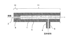
- 1 and 2 show a part of the drawing device from the vicinity of the drawing medium inlet 4 to the fiber inlet 2, and do not show the whole drawing device.
- FIGS. 1 and 2 the portion from the vicinity of the drawing medium inlet 4 to the fiber outlet is omitted.
- FIG. 5 partially shows the vicinity of the fiber inlet of the drawing device.
- the drawing apparatus includes a drawing chamber 1 that contains a drawing medium.
- the drawing chamber 1 is filled with the drawing medium.
- the drawing chamber 1 includes a fiber inlet 2, a fiber outlet (fiber outlet 3 in FIGS. 3, 4, and 6) and a drawing medium inlet 4.
- the drawing chamber 1 is formed in the space inside the container 5.
- the fiber inlet 2 is an opening of the container 5 for introducing fibers into the drawing chamber 1.
- the fiber inlet 2 is open to the external environment, ie the environment outside the drawing device (in particular the container 5).
- the fiber outlet is an opening of the container 5 for discharging the fiber from the drawing chamber 1.
- the fiber outlet is also open to the external environment.
- the drawing medium inlet 4 is an opening of the container 5 for supplying the drawing medium having a higher pressure than the external environment to the drawing chamber 1.
- a stretching medium supply pipe 6 for supplying a stretching medium from the outside to the stretching device is connected to the stretching medium inlet 4.
- the entire drawing chamber 1 is typically filled with the drawing medium (FIG. 1, etc.), as will be described later with reference to FIG. 4, there is a portion where the drawing medium does not exist in the fiber outlet 3 and its vicinity. May be.
- the pressure of the environment outside the container 5 may be negative pressure.
- environment pressure By setting the environmental pressure to a negative pressure, reduced pressure boiling can be used for boiling which will be described in detail later.
- the environment outside the container 5 may be atmospheric air, and setting the environmental pressure to atmospheric pressure is preferable from the viewpoint of simplifying the equipment.
- the drawing medium can be pressurized to a pressure above atmospheric pressure in order to be supplied from the drawing medium inlet 4.
- the environmental pressure may exceed atmospheric pressure.
- the stretching medium for example, water, alcohols such as ethanol and polyhydric alcohols such as ethylene glycol and glycerin can be used, and among them, water is particularly preferable in terms of cost and environment.
- the drawing medium is supplied to the drawing chamber 1 from the drawing medium inlet 4 in a state of a liquid having a higher pressure than the external environment. Particularly when the environmental pressure is atmospheric pressure, the drawing medium is pressurized to above atmospheric pressure and supplied from the drawing medium inlet 4 as described above. At this time, a pressure loss (differential pressure) due to a diaphragm 8 and boiling described later occurs, so that the drawing chamber 1 can be largely pressurized.
- the fact that the drawing medium is a liquid means the following. That is, when the temperature and the pressure of the stretching medium are represented by T and P, respectively, and the boiling point of the stretching medium at the pressure P is represented by Ta, T ⁇ Ta. In other words, when the saturated vapor pressure of the stretching medium at the temperature T is represented by Pa, P>Pa.
- the drawing medium supply pipe 6 may be provided with a pump (not shown), if necessary.
- High-pressure liquid drawing step The fibers are drawn in the drawing medium in a liquid state in which the pressure is higher than the external environment, which is supplied to the drawing chamber 1 (hereinafter, this step may be referred to as “high-pressure in-liquid drawing step”).
- the fibers are drawn and deformed in the liquid at a pressure higher than the external environment.
- the temperature of the drawing medium (liquid) at the time of drawing the fibers is set so that the fibers can be drawn and deformed.
- the fibers are continuously passed through the drawing chamber 1, and at that time, for example, using a plurality of rolls (not shown) provided outside the drawing device It is possible to continuously draw the fibers by increasing the drawing speed of the fibers.
- the drawing medium is discharged from the drawing chamber 1 through the fiber inlet 2.
- the drawing medium can also be discharged from the fiber outlet from the fiber outlet.
- the fiber outlet 3 is provided as shown in FIG. 3, the drawing medium is also discharged from the fiber outlet 3.
- a liquid column can be provided in the vicinity of the fiber outlet 3 to apply pressure to the drawing chamber, and in this case, the drawing medium is not discharged from the fiber outlet 3.
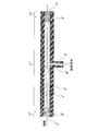
- the fiber outlet 3 is arranged at a position higher than the fiber inlet 2 so that the drawing medium is not discharged from the fiber outlet 3 due to the hydraulic pressure caused by the height difference between the fiber outlet 3 and the fiber inlet 2.
- the evaporated drawing medium may be dissipated from the fiber outlet 3 to the external environment.
- the drawing chamber 1 has a portion that extends horizontally from the fiber inlet 2 to the roll 20 and a portion that extends vertically upward from the roll 20 to the fiber outlet 3.
- a liquid surface 21 of the drawing medium is formed at a position lower than the fiber outlet 3 in a portion extending vertically upward.
- the roll 20 changes the traveling direction of the fiber, particularly from horizontal to vertically upward.
- the stretching medium discharged from the stretching chamber 1 can be appropriately collected.
- the recovered stretching medium may be circulated in the stretching chamber 1 for reuse.
- the pressure loss (difference between the drawing medium and the drawing medium flowing in the drawing chamber 1 (including a diaphragm 8 portion described later) is greater than that in the case of a liquid. Pressure) becomes significantly large.
- the confirmation that boiling occurs before discharging from the fiber inlet 2 can be visually confirmed depending on the configuration of the apparatus.
- the case A when introducing the liquid from the drawing medium inlet 4, when the case A and the case B having the same flow rate but different temperatures are carried out (the temperature of the case A>the temperature of the case B), the case A is the case. If the pressure loss (differential pressure) is high, it is recognized that Case A has boiled. This is because the viscosity of the liquid is lower in the case A where the temperature is higher, so that the pressure loss (differential pressure) is lower unless boiling occurs.
- the pressure loss (differential pressure) when the drawing medium flows through the drawing chamber 1 becomes significantly large due to boiling, it is possible to increase the opening size of the fiber inlet 2 and the running fiber contacts the drawing device. And, as a result, it is easy to prevent yarn breakage or fluff from occurring in the fiber. There is no need for precise processing of the fiber inlet 2. It is also possible to increase the pressure of the drawing medium supplied to the drawing chamber 1, and thus to increase the pressure in the high-pressure in-liquid drawing step. This means that it is possible to draw the fibers in the drawing medium in the higher temperature liquid state.
- the pressure loss can be further increased by providing the throttle 8 at the fiber inlet 2.
- a labyrinth seal can be used as the diaphragm. However, it is not necessary to use a diaphragm, and the cross-sectional area of the drawing chamber (the area of the cross section orthogonal to the fiber running direction) may be constant.
- the throttle is a member that causes a pressure loss in the fluid by providing a narrowing structure in the fluid passage.
- the labyrinth seal is a member provided with throttles in multiple stages, and causes pressure loss in the fluid by repeatedly providing a narrowing structure and a widening structure in the flow path of the fluid.
- the drawing medium discharged from the fiber inlet 2 is typically a gas-liquid two-phase composed of vapor and liquid (particularly droplets) at ambient pressure.
- Method 1 A drawing medium in a liquid state having a temperature higher than the boiling point at the environmental pressure and higher than the environmental pressure is supplied from the drawing medium inlet 4 to the drawing chamber 1. At the stage of being discharged from the fiber inlet 2, the drawing medium is released to the ambient pressure, so that the drawing medium boils before being discharged from the fiber inlet.
- the stretching device having the configuration shown in FIG. 1 can be used.
- the drawing medium is supplied to the drawing chamber 1 from the drawing medium supply pipe 6 through the drawing medium inlet 4.
- the drawing medium at this stage is in a liquid state having a temperature higher than the boiling point at the ambient pressure and higher than the ambient pressure. Therefore, the drawing medium supply pipe 6 can be provided with a heater (not shown) for heating the drawing medium and a pump (not shown) for pressurizing the drawing medium, if necessary.
- regions 11 and 12 exist in this order between the drawing medium inlet 4 and the fiber inlet 2.
- the fiber inlet 2 refers to the most advanced position where fibers are introduced into the device, as shown in detail in FIG.
- the region 11 is a region in the stretching chamber 1 in which the stretching medium is a liquid having a temperature higher than the boiling point at the ambient pressure and higher than the ambient pressure.
- the region 11 can be present not only between the drawing medium inlet 4 and the fiber inlet 2 but also between the drawing medium inlet 4 and the fiber outlet.
- the fibers are drawn in the drawing medium in a liquid state having a higher pressure than the external environment.
- the pressure of the drawing medium is slightly or substantially not decreased as it flows in the drawing chamber 1, but is drastically decreased particularly when it flows in the throttle 8, and the saturated vapor of the drawing medium at that temperature is reached. Reach pressure. At that point, the drawing medium begins to boil, and in region 12 the drawing medium boils. That is, the drawing medium boils before being discharged from the fiber inlet 2.
- ambient pressure vapor and liquid (droplets) are discharged from the fiber inlet 2.
- the area 12 may not reach the fiber inlet 2. That is, there may be a region (not shown) on the fiber inlet 2 side of the region 12 from the region 12 toward the fiber inlet 2 in which the vapor and the liquid at the environmental pressure flow while maintaining the mass ratio of the vapor and the liquid.
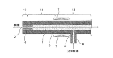
- ⁇ Method 2 The temperature of the drawing medium (liquid having a pressure higher than the environmental pressure) supplied to the drawing chamber 1 is set to be equal to or lower than the boiling point at the environmental pressure. Then, in the drawing chamber, the drawing medium is heated to a temperature exceeding the boiling point at the environmental pressure. When the temperature of the heated drawing medium reaches the boiling point at the pressure at this stage, it is possible to adjust the heating position and the heating temperature by keeping in mind that the drawing medium boils.
- the stretching device having the configuration shown in FIG. 2 can be used.
- the drawing medium supplied to the drawing chamber 1 is heated to a temperature exceeding the boiling point at the environmental pressure by the heater 7 arranged outside or inside (not shown) of the container 5.
- the heater 7 is provided so that the drawing medium flowing from the drawing medium inlet 4 toward the fiber inlet 2 can be heated in this way.
- regions 13, 11 and 12 exist in this order from the drawing medium inlet 4 to the fiber inlet 2.
- the region 13 is a region in the stretching chamber in which the stretching medium is a liquid having a temperature equal to or lower than the boiling point at the ambient pressure and higher than the ambient pressure.
- the region 13 can be present not only between the drawing medium inlet 4 and the fiber inlet 2 but also between the drawing medium inlet 4 and the fiber outlet.
- the drawing medium flowing from the drawing medium inlet 4 toward the fiber inlet 2 is heated by the heater 7 and becomes a liquid having a temperature equal to or higher than the boiling point at the environmental pressure (region 11).
- region 12 the drawing medium boils.
- region 11, or in regions 11 and 13 the fibers are drawn in a drawing medium that is in a liquid state at a pressure higher than the external environment. Typically, ambient pressure vapor and liquid (droplets) are discharged from the fiber inlet 2.
- the temperature, pressure and flow rate of the drawing medium supplied to the drawing medium inlet 4 and the amount of heat when heating in the drawing chamber 1 can be adjusted. ..
- the drawing medium can be heated by a heater provided outside or inside the container 5 in order to reach a temperature at which the fiber can be drawn and deformed.
- a heater provided outside or inside the container 5 for example, in the method 2, the heater 7 provided on the fiber inlet 2 side with respect to the drawing medium inlet 4 can be used, and/or the heater (non-heater provided on the fiber outlet side with respect to the drawing medium inlet 4 can be used). Shown) can be used.
- a heater provided on the fiber inlet 2 side of the drawing medium inlet 4 can be used for this heating, and/or on the fiber outlet side of the drawing medium inlet.
- the heater provided in can be used.
- the drawing medium does not have to be boiled before being discharged from the fiber outlet.
- the drawing medium can be discharged from the fiber outlet in the state of a liquid having a pressure higher than the environmental pressure.
- the drawing medium may be cooled to the boiling point of the environmental pressure or lower between the drawing medium inlet 4 and the fiber outlet and discharged from the fiber outlet.
- the drawing medium may not be discharged from the fiber outlet, as described above with reference to FIG.
- the drawing medium can be boiled before being discharged from the fiber outlet.
- a method of boiling the drawing medium the same method as the above-mentioned method 1 or 2 can be adopted.
- a restriction, especially a labyrinth seal, may or may not be provided at the fiber outlet.
- the portion from the drawing medium inlet 4 to the fiber inlet 2 has the configuration shown in FIG. 1, and the temperature of the drawing medium (liquid having a pressure higher than the environmental pressure) supplied to the drawing chamber 1 exceeds the boiling point at the environmental pressure.
- the portion from the drawing medium inlet 4 to the fiber outlet can have the same configuration as the portion from the drawing medium inlet 4 to the fiber inlet 2 shown in FIG. In this case, regions 11 and 12 are present in this order between the drawing medium inlet 4 and the fiber outlet.
- a typical example in this case is shown in FIG.
- the fiber inlet 2 side and the fiber outlet 3 side are symmetrical with respect to the position of the drawing medium inlet 4.
- the portion from the drawing medium inlet 4 to the fiber inlet 2 has the configuration shown in FIG. 2, and the temperature of the drawing medium (liquid having a pressure higher than the environmental pressure) supplied to the drawing chamber 1 is set to be equal to or lower than the boiling point at the environmental pressure.
- the portion from the drawing medium inlet 4 to the fiber outlet can have the same configuration (configuration shown in FIG. 3) as described above. However, in this case, the region 13 exists between the drawing medium inlet 4 and the fiber outlet 3, the regions 11 and 12 do not exist, and the drawing medium is discharged from the fiber outlet 3 in a liquid state.
- the pressure of the drawing medium at the drawing medium inlet 4 is preferably 50 to 900 kPaG.
- G means a gauge pressure (atmospheric pressure is a reference of zero pressure, and a pressure higher than atmospheric pressure is a positive value).
- this pressure is more preferably 100 kPaG or more, further preferably 170 kPaG or more, and most preferably 270 kPaG or more.
- the load on the device can be reduced by setting it to 900 kPaG or less.
- this pressure is more preferably 700 kPaG or less, further preferably 500 kPaG or less, and most preferably 450 kPaG or less.
- the pressure of the stretching medium in the liquid state exceeds the saturated vapor pressure at the stretching temperature of the stretching medium.
- the pressure described here is particularly preferable when the environmental pressure is atmospheric pressure. If the environmental pressure is different from the atmospheric pressure, the gauge pressure should be read as a relative value to the environmental pressure (the environmental pressure is a reference of pressure 0, and the pressure higher than the environmental pressure is a positive value). Is preferred.
- the optimum temperature of the drawing medium in the region 11 varies depending on the material forming the fiber.
- the temperature is preferably 100 to 170°C.
- the temperature is 100° C. or higher, the mobility of molecules constituting the fiber is increased and the drawability can be enhanced, and when the temperature is 170° C. or lower, it is easy to draw while maintaining the fiber form without melting. Become.
- it is more preferably 120° C. or higher and 165° C. or lower, and further preferably 130° C. or higher and 160° C. or lower.
- the temperature is preferably 100 to 220°C.
- the temperature is 100° C. or higher, the mobility of the molecules constituting the fiber is enhanced and the stretchability can be enhanced, and when the temperature is 220° C. or lower, the stretching is performed while maintaining the quality without causing decomposition or flame resistance reaction. It will be easy.
- the temperature is more preferably 120° C. or higher and 200° C. or lower, and further preferably 130° C. or higher and 160° C. or lower.
- the temperature is preferably 150 to 340°C.
- the temperature is 150° C. or higher, the mobility of molecules constituting the fiber is enhanced and the stretchability can be enhanced, and when the temperature is 340° C. or lower, it is easy to stretch while maintaining the fiber form without melting. Become.
- the temperature is more preferably 200° C. or higher and 320° C. or lower, and further preferably 250° C. or higher and 300° C. or lower.
- the material of the fiber to be drawn is not particularly limited, and examples thereof include polypropylene, polyacrylonitrile, cellulose acetate, polyurethane, polyvinyl chloride, viscose rayon, nylon, polyester, polyether ether ketone (PEEK) and the like. Fiber bundles can be used as the fibers.
- the stretch deformation of the fibers preferably occurs in the area 11 in the case of the method 1, in the area 11 in the case of the method 2, or in the areas 11 and 13.
- the fibers it is permissible for the fibers to be drawn not only in regions 11 and 13 but also in region 12 where the drawing medium is boiling.
- the fiber inlet 2 side of the region 12 from the region 12 toward the fiber inlet 2 where the vapor and the liquid at the environmental pressure flow while maintaining the mass ratio of the vapor and the liquid, the fiber is stretched in that region. It is also permissible for some of the deformation to occur. It is also allowed that a part of the stretching deformation of the fiber occurs between the drawing medium inlet 4 and the fiber outlet 3 and further after exiting the fiber outlet 3.
- the drawing medium inlet 4 can be provided at a position closer to the fiber outlet than the center of the drawing chamber (the center in the fiber running direction). This is preferable when the heater is installed on the fiber inlet 2 side of the drawing medium inlet 4 and the heater is not installed on the fiber outlet side of the drawing medium inlet 4.
- the drawing medium inlet 4 can also be provided in the center of the drawing chamber.
- the drawing medium inlet 4 may be provided at a position closer to the fiber inlet 2 than the center of the drawing chamber.
- the stretching device shown in FIGS. 1, 2, 3 and 6 is a horizontal type. Therefore, the fiber yarn path is substantially horizontal.
- the present invention is not limited to this, and the stretching device may be a vertical type. Alternatively, as shown in FIG. 4, the stretching device may include a horizontal portion and a vertical portion.
- the shape of the cross section (cross section orthogonal to the fiber running direction) of the drawing chamber is not particularly limited, and is, for example, a circular shape or a rectangular shape (slit shape).
- the length of the region 12 is 30 mm or more, it is easy to obtain the effect of pressure loss utilizing the gas phase formed by boiling, and when it is 300 mm or less, the length of the region 12 is less than that of fluff due to rubbing of fibers. It is preferable from the viewpoint of preventing troubles. From the above, the length of the region 12 is preferably 30 mm or more and 300 mm or less, and more preferably 50 mm or more and 200 mm or less.
- the time (hereinafter, sometimes referred to as “pre-staying time”) t from when the fiber passes through the fiber inlet 2 to the temperature at which the fiber can be stretched and deformed is preferably It is 0.2 seconds or more, more preferably 0.5 seconds or more.
- the dimensions of the stretching chamber (in particular, the region 11) and the temperature of the stretching medium can be adjusted so that such a pre-residence time t can be achieved and a desired stretching can be performed thereafter.
- the minimum dimension of the cross section of the drawing chamber where there is no restriction is from 10 mm to 30 mm.
- the minimum dimension of the cross section of the drawing chamber is the diameter when the cross section of the drawing chamber is circular, and the length of the short side when the cross section of the drawing chamber is rectangular.
- the minimum dimension of the cross section of the drawing chamber is 10 mm or more, it is easy to slow down the speed of the drawing medium flowing in the drawing chamber, and it is easy to pass the fiber through the device without receiving a large resistance from the drawing medium. ..
- the minimum dimension of the cross section of the drawing chamber is 30 mm or less, it is easy to fill the drawing medium in the apparatus without using a large amount of drawing medium, and it is easy to efficiently produce drawn fibers.
- the occupation ratio of the fiber (fiber bundle) cross section with respect to the cross sectional area of the restriction is 2% or more and 70% or less. If the occupancy rate is 2% or more, it is easy to increase the pressure loss. When the occupancy rate is 70% or less, it is easy to prevent the fiber from hitting the device due to some trouble and causing quality deterioration such as yarn breakage and fluff.
- the occupation ratio of the cross section of the fiber (fiber bundle) to the cross-sectional area of the drawing chamber is 2% or more and 70% or less, as in the case of the throttle. ..
- the length of the diaphragm 8 may be relatively short.
- the length of the diaphragm 8 can be shorter than the lengths of the regions 11 and 13.
- the temperature difference can be increased inside the diaphragm 8. The larger the temperature difference between the inner side end and the outer side end of the drawing device 8 is, the easier the uniform drawing. From this viewpoint, the temperature difference is preferably 10° C. or higher, and more preferably 50° C. or higher.
- the drawing medium pressure at the inner end of the drawing device of the drawing device 8 is preferably 50 kPa or more higher than the environmental pressure, and more preferably 400 kPa or more higher than the environmental pressure. ..
- the pressure described here is particularly preferable when the environmental pressure is atmospheric pressure.
- the drawing medium flowing from the drawing medium inlet 4 to the fiber inlet 2 has the function of raising the temperature of the fibers introduced from the fiber inlet 2 and the function of absorbing the heat generated when the fibers in the drawing device are drawn and deformed.
- the flow rate of the drawing medium flowing from the drawing medium inlet 4 to the fiber inlet 2 is 10 times or more the volume of the fibers introduced from the fiber inlet 2 per unit time. Is preferred.
- the flow rate of the stretching medium is preferably 1 L/min (1 liter per 60 seconds) or more. From the viewpoint of damage to the fibers, the flow rate of the drawing medium is preferably 20 L/min or less.
- the flow rate of the drawing medium flowing from the drawing medium inlet 4 to the fiber outlet is not particularly limited, but a low flow rate is preferable.
- the fiber introduction speed and the fiber extraction speed can be appropriately determined depending on the desired draw ratio and productivity, but the fiber introduction speed is preferably 1 m/min (1 meter per 60 seconds) or more from the viewpoint of productivity. Further, it is preferable that the fiber delivery speed is 4000 m/min or less from the viewpoint of safety during production.
- Fiber polypropylene fiber (manufactured by Nippon Polypro Co., trade name "SA01A", melt flow rate: 10 g/10 minutes (230°C, load 2.16 kg), fineness of fiber bundle before stretching: 9260 dtex, number of filaments of fiber bundle: 240),
- Drawing chamber cylindrical, diameter 26 mm, length 2.4 m (distance in fiber running direction from fiber inlet to fiber outlet),
- Labyrinth seal 8 steps, small diameter 4 mm, large diameter 22 mm, length about 175 mm.
- the tensile strength and tensile elongation of the obtained fiber were measured. In addition, the presence or absence of whitening of the fibers was visually confirmed. The results are shown in Table 1.
- the temperature of the drawing medium did not substantially change from the drawing medium inlet 4 to the region 11, dropped sharply in the region 12, and was 100° C. at the fiber inlet 2 and the fiber outlet 3. Boiling was confirmed at the fiber inlet 2 and the fiber outlet 3, and a gas-liquid two-phase flow (steam and droplets) was discharged from each.
- Example 1 although the fiber was drawn with a high productivity of 160 m/min, the fiber did not whiten.
- Example 1-2 The same experiment as in Example 1 was performed except that a sight glass was attached to the stretching chamber 1 of the stretching device used in Example 1 so that the inside of the stretching chamber could be observed. It was confirmed that water vapor and hot water were jetted from the fiber inlet 2 in a mixed state, and the fiber bundle was filled with the liquid without bringing air into the drawing chamber.
- Example 2 The same test as in Example 1 was performed except that the conditions were changed as described in Table 1. The evaluation results are shown in Table 1. The temperature of the drawing medium did not substantially change from the drawing medium inlet 4 to the region 11, dropped sharply in the region 12, and was 100° C. at the fiber inlet 2 and the fiber outlet 3. Boiling was confirmed at the fiber inlet 2 and the fiber outlet 3, and a gas-liquid two-phase flow (steam and droplets) was discharged from them. In Example 2, although the fiber was drawn with a high productivity of 160 m/min, the fiber did not whiten.
- Example 2-2 The same experiment as in Example 2 was carried out except that a sight glass was attached to the stretching chamber 1 of the stretching device used in Example 2 so that the state inside the stretching chamber could be observed. It was confirmed that water vapor and hot water were jetted from the fiber inlet 2 in a mixed state, and the fiber bundle was filled with the liquid without bringing air into the drawing chamber.
- Example 1 The same test as in Example 1 was performed except that the stretching medium was steam as described in Table 1 and the steam pressure was adjusted so that the stretching medium temperature at the inlet of the stretching medium was the same as in Example 1. As shown in the evaluation results in Table 1, the fibers were whitened.
- Example 3 A stretching device having the configuration shown in FIG. 6 was prepared.
- This drawing apparatus looks the same as the drawing apparatus used in Example 1 (see FIG. 3) in a schematic sectional view, but the drawing chamber of the drawing apparatus of Example 1 is cylindrical (perpendicular to the fiber running direction). While the cross section was circular), the drawing chamber of the drawing apparatus of Example 3 had a rectangular parallelepiped shape (the cross section orthogonal to the fiber running direction was rectangular).
- drawing chamber 1' Each component (drawing chamber 1', fiber inlet 2', fiber outlet 3', drawing medium inlet 4', container 5', drawing medium supply pipe 6', throttle 8', region 11' and region 12')
- the drawing chamber 1′ and the throttle (labyrinth seal) 8′ were configured so that their cross sections orthogonal to the fiber running direction were rectangular.
- the drawing medium inlet 4' was provided at the center of the drawing chamber in the fiber running direction.
- a labyrinth seal having the same structure was provided as a diaphragm 8'on each of the fiber inlet 2'and the fiber outlet 3'.
- the fiber drawing speed was gradually changed (increased) under the conditions shown in Table 2 and below, and the fibers were drawn until they were broken.
- Environmental pressure atmospheric pressure
- Fiber acrylic fiber (single yarn fineness 3dtex)
- Drawing chamber rectangular parallelepiped, the drawing chamber cross section (cross section orthogonal to the fiber running direction) is a rectangle of 30 mm in the vertical direction and 38 mm in the horizontal direction, and the length of the drawing chamber is 2.00 m (fiber running from the fiber inlet to the fiber outlet. Direction distance)
- Labyrinth seal 32 stages of narrowing, width of narrowing structure part 2.0 mm, width of widening structure part 12 mm, length about 460 mm.
- Table 2 shows the draw ratio at break of the obtained fiber and the evaluation result of the drawability.
- the temperature of the drawing medium did not substantially change from the drawing medium inlet 4 to the region 11, dropped sharply in the region 12, and was 100° C. at the fiber inlet 2 and the fiber outlet 3. Boiling was confirmed at the fiber inlet 2 and the fiber outlet 3, and a gas-liquid two-phase flow (steam and droplets) was discharged from each.
- Example 3-2 The same experiment as in Example 3 was carried out except that a sight glass was attached to the stretching chamber 1 of the stretching device used in Example 3 so that the state inside the stretching chamber could be observed. It was confirmed that water vapor and hot water were jetted from the fiber inlet 2 in a mixed state, and the fiber bundle was filled with the liquid without bringing air into the drawing chamber.
- Example 2 The same test as in Example 3 was carried out except that the drawing medium was steamed as described in Table 2 and the steam pressure was adjusted so that the drawing medium temperature and pressure at the drawing medium inlet were the same as in Example 3. It was The evaluation results are shown in Table 2. In Example 3, it broke when stretched to 5.6 times, but in Comparative Example 2, it broke when stretched 4.2 times.
- Example 4 The same test as in Example 3 was carried out except that the width of the narrowed structure portion of the labyrinth seal was set to 2.5 mm and the conditions were changed as shown in Table 2. The evaluation results are shown in Table 2. The temperature of the drawing medium did not substantially change from the drawing medium inlet 4 to the region 11, dropped sharply in the region 12, and was 100° C. at the fiber inlet 2 and the fiber outlet 3. Boiling was confirmed at the fiber inlet 2 and the fiber outlet 3, and a gas-liquid two-phase flow (steam and droplets) was discharged from each.
- Example 4-2 An experiment similar to that in Example 4 was performed, except that a sight glass was attached to the stretching chamber 1 of the stretching device used in Example 4 so that the inside of the stretching chamber could be observed. It was confirmed that water vapor and hot water were jetted from the fiber inlet 2 in a mixed state, and the fiber bundle was filled with the liquid without bringing air into the drawing chamber.
- Example 3 The same test as in Example 4 was carried out except that the drawing medium was steamed as shown in Table 2 and the steam pressure was adjusted so that the drawing medium temperature and pressure at the drawing medium inlet were the same as in Example 4. It was The evaluation results are shown in Table 2. In Example 4, it broke when stretched up to 5.2 times, but in Comparative Example 3, it broke at a stretch of 3.4 times.
- Example 4 and Comparative Example 3 the fineness of the fiber bundle before stretching is twice that of Example 3 and Comparative Example 2. At this time, it was confirmed that the stretchability of Example 4 was less likely to decrease than that of Comparative Example 3.
- Stretching Chamber 2 Fiber Inlet 3 Fiber Outlet 4 Stretching Medium Inlet 5 Container 6
- Stretching Medium Supply Pipe 7 Heater 8 Throttling 11 Region 12 where the stretching medium is a liquid having a temperature above the boiling point at ambient pressure and higher than ambient pressure 12 Stretching Region in which the medium boils 13 Region in which the stretching medium is a liquid having a temperature equal to or lower than the boiling point at the ambient pressure and having a pressure higher than the ambient pressure 20 Roll 21 Liquid level
Landscapes
- Engineering & Computer Science (AREA)
- Textile Engineering (AREA)
- Yarns And Mechanical Finishing Of Yarns Or Ropes (AREA)
Abstract
L'invention concerne un procédé permettant de produire une fibre étirée, qui peut empêcher un blanchissement de fibre et dans lequel l'extensibilité est peu susceptible d'être affectée par la finesse d'un faisceau de fibres. Ce procédé permettant de produire une fibre étirée consiste à faire passer une fibre à travers une chambre d'étirage qui a une entrée de fibre ouverte vers l'environnement externe et qui stocke un milieu d'étirage ayant une pression supérieure à celle de l'environnement externe, pour étirer la fibre, le procédé comprenant : une étape consistant à fournir le milieu d'étirage dans un état d'un liquide ayant une pression supérieure à celle de l'environnement externe à la chambre d'étirage ; une étape consistant à étirer la fibre dans le milieu d'étirage liquide dans un état d'un liquide ayant une pression supérieure à celle de l'environnement externe ; et une étape consistant à évacuer le milieu d'étirage à travers l'entrée de fibre, le milieu d'étirage étant porté à ébullition avant d'être évacué par l'entrée de fibre.
Priority Applications (1)
| Application Number | Priority Date | Filing Date | Title |
|---|---|---|---|
| JP2020520168A JP7318642B2 (ja) | 2018-11-29 | 2019-11-26 | 延伸繊維の製造方法 |
Applications Claiming Priority (2)
| Application Number | Priority Date | Filing Date | Title |
|---|---|---|---|
| JP2018-223127 | 2018-11-29 | ||
| JP2018223127 | 2018-11-29 |
Publications (1)
| Publication Number | Publication Date |
|---|---|
| WO2020111026A1 true WO2020111026A1 (fr) | 2020-06-04 |
Family
ID=70853963
Family Applications (1)
| Application Number | Title | Priority Date | Filing Date |
|---|---|---|---|
| PCT/JP2019/046066 Ceased WO2020111026A1 (fr) | 2018-11-29 | 2019-11-26 | Procédé pour produire une fibre étirée |
Country Status (2)
| Country | Link |
|---|---|
| JP (1) | JP7318642B2 (fr) |
| WO (1) | WO2020111026A1 (fr) |
Citations (6)
| Publication number | Priority date | Publication date | Assignee | Title |
|---|---|---|---|---|
| JPS5094221A (fr) * | 1973-12-26 | 1975-07-26 | ||
| JPS60193632A (ja) * | 1984-03-16 | 1985-10-02 | Asahi Chem Ind Co Ltd | 高分子材料の連続加圧延伸装置 |
| JPH03833A (ja) * | 1989-02-24 | 1991-01-07 | Mas Fab Rieter Ag | 合成繊維の流体力学的延伸方法及び装置 |
| JPH0544132A (ja) * | 1991-08-01 | 1993-02-23 | Mitsubishi Rayon Co Ltd | アクリル系重合体糸条の加圧スチーム延伸装置 |
| JPH0657573A (ja) * | 1992-06-09 | 1994-03-01 | Mitsubishi Rayon Co Ltd | 糸条の加圧スチーム処理装置及びその方法 |
| JPH08246284A (ja) * | 1995-03-06 | 1996-09-24 | Toray Ind Inc | スチーム延伸装置およびスチーム延伸方法 |
-
2019
- 2019-11-26 WO PCT/JP2019/046066 patent/WO2020111026A1/fr not_active Ceased
- 2019-11-26 JP JP2020520168A patent/JP7318642B2/ja active Active
Patent Citations (6)
| Publication number | Priority date | Publication date | Assignee | Title |
|---|---|---|---|---|
| JPS5094221A (fr) * | 1973-12-26 | 1975-07-26 | ||
| JPS60193632A (ja) * | 1984-03-16 | 1985-10-02 | Asahi Chem Ind Co Ltd | 高分子材料の連続加圧延伸装置 |
| JPH03833A (ja) * | 1989-02-24 | 1991-01-07 | Mas Fab Rieter Ag | 合成繊維の流体力学的延伸方法及び装置 |
| JPH0544132A (ja) * | 1991-08-01 | 1993-02-23 | Mitsubishi Rayon Co Ltd | アクリル系重合体糸条の加圧スチーム延伸装置 |
| JPH0657573A (ja) * | 1992-06-09 | 1994-03-01 | Mitsubishi Rayon Co Ltd | 糸条の加圧スチーム処理装置及びその方法 |
| JPH08246284A (ja) * | 1995-03-06 | 1996-09-24 | Toray Ind Inc | スチーム延伸装置およびスチーム延伸方法 |
Also Published As
| Publication number | Publication date |
|---|---|
| JPWO2020111026A1 (ja) | 2021-10-14 |
| JP7318642B2 (ja) | 2023-08-01 |
Similar Documents
| Publication | Publication Date | Title |
|---|---|---|
| CN101588911B (zh) | 具有毛细孔道的挤出材料 | |
| EP3778999A1 (fr) | Procédé de fabrication d'un faisceau de fibres d'acrylonitrile et procédé de fabrication d'un faisceau de fibres de carbone | |
| US8858851B2 (en) | Method for producing lower size, high tenacity and high modulus polyethylene fiber | |
| CN101568672B (zh) | 用于制备UHMW复丝聚(α-烯烃)纱的方法 | |
| JP6149583B2 (ja) | 炭素繊維前駆体アクリル繊維束の延伸方法 | |
| TW393527B (en) | Process for the production of a polyester multifilament yarn | |
| JP7010214B2 (ja) | アクリロニトリル系繊維束の製造方法および炭素繊維束の製造方法 | |
| WO2020111026A1 (fr) | Procédé pour produire une fibre étirée | |
| JP2013159874A (ja) | アクリル繊維束の製造方法と同繊維束のスチーム延伸装置 | |
| TW584680B (en) | Device for intermingling, relaxing, and/or thermosetting of filament yarn in a melt spinning process, as well as associated processes and the filament yarn manufactured therewith | |
| JP2009215680A (ja) | ポリフェニレンサルファイド繊維の製造方法およびポリフェニレンサルファイド繊維 | |
| WO1999050490A1 (fr) | Procede d'etirage et materiau etire | |
| US3126434A (en) | Damping of surface movement of quench bath in | |
| JP4673095B2 (ja) | 加圧スチーム延伸装置およびアクリル系繊維の製造方法 | |
| CN109844188B (zh) | 用于单丝纱线生产的系统及方法 | |
| US3994052A (en) | Method and apparatus for texturing yarn | |
| JP6962453B2 (ja) | 繊維延伸装置 | |
| JP6562187B1 (ja) | アクリロニトリル系繊維束の製造方法および炭素繊維束の製造方法 | |
| US3977057A (en) | Apparatus for the production of yarn | |
| JP6265068B2 (ja) | 炭素繊維前駆体アクリル繊維束の製造方法 | |
| JP2008075205A (ja) | 加圧スチームによる繊維の延伸方法及び延伸装置、並びに炭素繊維用アクリル系前駆体繊維束の製造方法 | |
| JP4332401B2 (ja) | 加圧スチーム延伸装置およびアクリル系繊維の製造方法 | |
| US1950025A (en) | Manufacture of artificial filaments or threads | |
| JP2002180347A (ja) | 結晶性高分子延伸物の製造方法 | |
| CN106480521A (zh) | 干‑湿法纺丝机 |
Legal Events
| Date | Code | Title | Description |
|---|---|---|---|
| ENP | Entry into the national phase |
Ref document number: 2020520168 Country of ref document: JP Kind code of ref document: A |
|
| 121 | Ep: the epo has been informed by wipo that ep was designated in this application |
Ref document number: 19888812 Country of ref document: EP Kind code of ref document: A1 |
|
| NENP | Non-entry into the national phase |
Ref country code: DE |
|
| 122 | Ep: pct application non-entry in european phase |
Ref document number: 19888812 Country of ref document: EP Kind code of ref document: A1 |