WO2020121374A1 - 非燃焼加熱型喫煙装置 - Google Patents
非燃焼加熱型喫煙装置 Download PDFInfo
- Publication number
- WO2020121374A1 WO2020121374A1 PCT/JP2018/045294 JP2018045294W WO2020121374A1 WO 2020121374 A1 WO2020121374 A1 WO 2020121374A1 JP 2018045294 W JP2018045294 W JP 2018045294W WO 2020121374 A1 WO2020121374 A1 WO 2020121374A1
- Authority
- WO
- WIPO (PCT)
- Prior art keywords
- heater
- tobacco rod
- region
- smoking device
- internal heater
- Prior art date
- Legal status (The legal status is an assumption and is not a legal conclusion. Google has not performed a legal analysis and makes no representation as to the accuracy of the status listed.)
- Ceased
Links
Images


Classifications
-
- A—HUMAN NECESSITIES
- A24—TOBACCO; CIGARS; CIGARETTES; SIMULATED SMOKING DEVICES; SMOKERS' REQUISITES
- A24F—SMOKERS' REQUISITES; MATCH BOXES; SIMULATED SMOKING DEVICES
- A24F40/00—Electrically operated smoking devices; Component parts thereof; Manufacture thereof; Maintenance or testing thereof; Charging means specially adapted therefor
- A24F40/40—Constructional details, e.g. connection of cartridges and battery parts
- A24F40/46—Shape or structure of electric heating means
-
- A—HUMAN NECESSITIES
- A24—TOBACCO; CIGARS; CIGARETTES; SIMULATED SMOKING DEVICES; SMOKERS' REQUISITES
- A24F—SMOKERS' REQUISITES; MATCH BOXES; SIMULATED SMOKING DEVICES
- A24F40/00—Electrically operated smoking devices; Component parts thereof; Manufacture thereof; Maintenance or testing thereof; Charging means specially adapted therefor
- A24F40/50—Control or monitoring
- A24F40/57—Temperature control
-
- A—HUMAN NECESSITIES
- A24—TOBACCO; CIGARS; CIGARETTES; SIMULATED SMOKING DEVICES; SMOKERS' REQUISITES
- A24F—SMOKERS' REQUISITES; MATCH BOXES; SIMULATED SMOKING DEVICES
- A24F40/00—Electrically operated smoking devices; Component parts thereof; Manufacture thereof; Maintenance or testing thereof; Charging means specially adapted therefor
- A24F40/20—Devices using solid inhalable precursors
Definitions
- the present invention relates to a non-combustion heating type smoking device.
- Non-combustion heating type smoking device that delivers aerosols to smokers generated by heating a tobacco rod that contains chopped tobacco and aerosol-generating base materials (glycerin, propylene glycol, etc.) with a heater such as an electric heater.
- a heater such as an electric heater.
- the present invention has been made in view of the above circumstances, the object is to suppress the condensation of the aerosol generated by heating, it is possible to deliver a sufficient amount of aerosol to smokers non-combustion It is to provide a heating type smoking device.
- a non-combustion heating type smoking device for solving the above-mentioned problems, a housing cavity for housing a tobacco rod containing a tobacco cut and an aerosol-generating substrate, and the housing cavity arranged in the housing cavity, An internal heater for penetrating into a tobacco rod inserted in or inserted into a recess formed in the end surface of the tobacco rod, for volatilizing the aerosol-generating substrate by heating the tobacco rod from the inside.
- An inner heater and a side peripheral portion of the accommodating cavity are provided, and at least the outer peripheral portion of the tobacco rod is preheated during the preheating period of the tobacco rod to suppress condensation of aerosol generated when the inner heater is operated. And an external heater.
- the controller includes a controller that controls the internal heater and the external heater, and the controller controls the temperature of the external heater to be the temperature of the internal heater during a simultaneous heating period in which both the internal heater and the external heater operate. You may control so that it may become higher.
- control unit when the elapsed time from the preheating start of the tobacco rod by the external heater reaches a predetermined set time, or when the temperature of the external heater reaches a predetermined set temperature, although the operation is stopped, the operation of the internal heater may be continued.
- the control unit may increase the temperature of the internal heater after the operation of the external heater is stopped compared to before the operation of the external heater is stopped.
- the control unit may start the preheating by operating only the external heater when starting the preheating of the tobacco rod, and may operate the internal heater after the operation of the external heater.
- the accommodating cavity is located at a tip end side of the side peripheral portion and has an insertion opening that is an open end that is opened so that the tobacco rod can be inserted, and a cavity bottom portion that is located at a proximal end side of the side peripheral portion.
- the side peripheral portion has a first region including a base end on which the cavity bottom is provided, and a second region adjacent to the first region and located on the insertion opening side, The external heater may not be arranged in the first region and may be arranged in the second region.
- the external heater may be arranged over the entire circumference along the circumferential direction of the side circumferential part in a part or the whole section of the second region.
- the internal heater may have n-fold symmetry with respect to the central axis of the accommodation cavity, and n may be an integer of 3 or more.
- the internal heater may have a columnar shape, and a conical portion may be formed on the tip side.
- the internal heater may have a truncated cone shape or a truncated cone shape, and may be tapered from the cavity bottom side toward the insertion port side.
- the internal heater may have a conical shape or a truncated cone shape.
- the side peripheral portion may further have a third region adjacent to the second region and including the insertion port, and the external heater may not be arranged in the third region.
- the tip position of the internal heater may be associated with the second region or the third region of the side peripheral portion.
- the means for solving the problems in the present invention can be adopted in combination as much as possible.
- a non-combustion heating type smoking device capable of suppressing condensation of aerosol generated by heating and delivering a sufficient amount of aerosol to a smoker.
- FIG. 1 is a diagram schematically showing the internal structure of the non-combustion heating type smoking device according to the first embodiment.
- FIG. 2 is a schematic configuration diagram of a non-combustion heating type smoking article used in the non-combustion heating type smoking device.
- FIG. 3 is a schematic view of a vertical cross section of the heater.
- FIG. 4 is a perspective view showing a schematic structure of the heater.
- FIG. 5 is a figure which shows the state which inserted the tobacco rod of the non-combustion heating type smoking article into the accommodation cavity from the insertion port in a heater.
- FIG. 6 is a figure which shows the state which inserted the tobacco rod of the non-combustion heating type smoking article into the accommodation cavity from the insertion port in a heater.
- FIG. 5 is a figure which shows the state which inserted the tobacco rod of the non-combustion heating type smoking article into the accommodation cavity from the insertion port in a heater.
- FIG. 6 is a figure which shows the state which inserted the
- FIG. 7 is a time chart showing the operating states of the external heater and the internal heater during heating control.
- FIG. 8 is a diagram for explaining changes in the surface temperature of the external heater and the internal heater during heating control.
- FIG. 9 is a figure which shows the result of a temperature measurement test.
- FIG. 10 is a figure which shows the result of a temperature measurement test.
- FIG. 11 is a figure which shows the result of a temperature measurement test.
- FIG. 12 is a figure which shows the result of a temperature measurement test.
- FIG. 13 is a diagram showing the product temperature measurement position of the tobacco rod.
- FIG. 14 is a figure which shows the modification of the internal heater in a heater.
- FIG. 15 is a figure which shows the modification of the internal heater in a heater.
- FIG. 16 is a figure which shows the modification of the internal heater in a heater.
- FIG. 1 is a diagram schematically showing an internal structure of a non-combustion heating type smoking device 1 according to the first embodiment.
- the non-combustion heating type smoking device 1 has a housing 2 which is a housing for housing various components.
- a heater 3, a controller (control unit) 4, a power supply 5 and the like are housed in the housing 2.
- FIG. 2 is a schematic configuration diagram of a non-combustion heating smoking article 10 used in the non-combustion heating smoking device 1.
- the non-combustion heating type smoking article 10 has a tobacco rod 11 and a mouthpiece portion 12.
- the end of the non-combustion heating type smoking article 10 on the side of the tobacco rod 11 is referred to as a tip
- the end of the mouthpiece portion 12 is referred to as a base end.
- the tobacco rod 11 is composed of a filler 111 including a tobacco cut and an aerosol-generating base material, and a wrapping paper 112 around which the filler 111 is wound.
- the material for cutting the tobacco is not particularly limited, but known materials such as lamina and mid-bone can be used.
- the filling material 111 includes an aerosol-generating base material that generates an aerosol.
- the type of aerosol-forming base material is not particularly limited, and various substances extracted from natural products can be appropriately selected depending on the application.
- the aerosol-forming base material include glycerin, propylene glycol, triacetin, 1,3-butanediol, and mixtures thereof.
- homogenized tobacco such as tobacco fine powder, and as a binder, a gelling agent, a cross-linking agent, a fragrance, a hydrophilic fragrance, a lipophilic fragrance, and a viscosity adjustment are added.
- the filling material 111 may include a fragrance.
- the type of fragrance is not particularly limited.
- the mouthpiece part 12 includes, for example, a filter segment or the like in which cylindrical cellulose acetate is wrapped with a roll of paper, and filters part of the aerosol generated by the tobacco rod 11 during smoking.
- the mouthpiece portion 12 may include a segment other than the filter segment.
- the tobacco rod 11 and the mouthpiece portion 12 are connected to each other by being integrally wound by a tip paper 13.
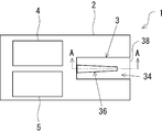
- FIG. 3 is a schematic view of a vertical cross section of the heater 3. Specifically, FIG. 3 shows a sectional structure of the heater 3 taken along the line AA in FIG.
- FIG. 4 is a perspective view showing a schematic structure of the heater 3.
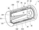
- the heater 3 has a heater housing 31 having a bottomed cylindrical shape.
- the heater housing 31 has a disk-shaped bottom portion 311 and a cylindrical outer cylinder wall 312 rising from the bottom portion 311.
- the opening end of the outer cylinder wall 312 of the heater housing 31 is open toward the outside of the housing 2 through an opening provided in the housing 2, and is a column into which the tobacco rod 11 of the non-combustion heating type smoking article 10 can be inserted.
- An accommodation cavity 34 which is a hollow shape, is formed.
- a thick portion 313 having a smaller inner diameter by one step than other portions is formed on the tip side of the outer cylinder wall 312 of the heater housing 31.
- the front end of the outer cylinder wall 312 here refers to the end of the outer cylinder wall 312 opposite to the base end connected to the bottom portion 311.
- a cavity side peripheral wall 32 having a cylindrical shape is provided inside the outer cylindrical wall 312 of the heater housing 31.
- the outer diameter of the cavity side peripheral wall 32 is equal to the inner diameter of the thick portion 313 of the outer cylindrical wall 312.
- an annular and hollow air heat insulating portion 37 is formed between the inner surface of the outer cylindrical wall 312 of the heater housing 31 and the outer peripheral surface 32b of the cavity side peripheral wall 32.
- an insertion opening 38 is formed which is opened so that the tobacco rod 11 can be inserted.
- the end of the cavity side peripheral wall 32 opposite to the tip side where the insertion port 38 is formed is referred to as a base end 32c.
- a heat resistant cup 33 having a bottomed cylindrical shape is provided on the bottom 311 side of the heater housing 31.
- the heat-resistant cup 33 is made of a heat-resistant material such as aluminum, and has a disk-shaped cavity bottom 331 and a cavity-side peripheral wall 332 rising from the cavity bottom 331.
- the cavity bottom portion 331 of the heat-resistant cup 33 is arranged in a state of being stacked inside the bottom portion 311 of the heater housing 31, and forms the cavity bottom portion of the accommodation cavity 34. Further, the cavity side peripheral wall 32 and the cavity side peripheral wall 332 form a side peripheral portion of the accommodation cavity 34.
- the heat-resistant cup 33 and the cavity-side peripheral wall 32 form an accommodation cavity 34 that is a cavity for accommodating the tobacco rod 11.
- an annular external heater 35 is provided on the cavity side peripheral wall 32 so as to face the accommodation cavity 34.
- the external heater 35 is housed in the concave portion of the cavity side peripheral wall 32 so as to be flush with the inner peripheral surface 32 a of the cavity side peripheral wall 32.
- the reference numeral 35 a is a heating surface facing the accommodation cavity 34.
- the ring-shaped external heater 35 is arranged along the entire inner circumference of the cavity-side peripheral wall 32 along the inner peripheral surface 32a.
- the external heater 35 is arranged along the circumferential direction of the accommodation cavity 34 over the entire circumference of the side peripheral portion.
- the reference numeral CL1 shown in FIG. 3 is the central axis of the heater housing 31.
- the central axis CL1 is also the central axis of the accommodation cavity 34 and the cavity side peripheral wall 32 at the same time.
- an internal heater 36 is provided in the accommodation cavity 34.
- the internal heater 36 has a truncated cone shape, and is vertically provided from the central portion of the bottom portion 311 of the heater housing 31 toward the accommodation cavity 34 side.
- a through hole 33a is formed in the center of the cavity bottom portion 331 of the heat resistant cup 33, and the internal heater 36 projects from the cavity bottom portion 331 to the accommodation cavity 34 side by inserting the through hole 33a.
- the central axis of the internal heater 36 is coaxial with the central axis CL of the heater housing 31 (accommodation cavity 34).
- Reference numeral 36a is a base end portion of the internal heater 36
- reference numeral 36b is a front end portion of the internal heater 36.
- the internal heater 36 extends from the cavity bottom portion 331 toward the insertion opening 38, and is gradually tapered from the base end portion 36a to the tip end portion 36b.
- the types of the internal heater 36 and the external heater 35 are not particularly limited, but, for example, a steel material having heating wires (for example, nichrome, iron chrome, iron nickel, etc.) stretched around, a ceramic heater, or a sheath heater ( Sheathed Heater) can be used.
- the sheathed heater is a heater in which heat rays are covered with a filler and a metal pipe.
- the cavity side peripheral wall 32 is formed of a known heat insulating and heat resistant material so as to withstand the heat of the external heater 35 and prevent the heat of the external heater 35 from diffusing.
- the material used for the cavity-side peripheral wall 32 having such heat insulation performance and heat resistance performance include ceramics of alumina/silica, PEEK (polyether ether ketone), PPS (polyphenylene sulfide), and PTFE (polytetrahydrofuran) having high heat resistance.
- resins such as fluoroethylene).
- the inner peripheral surface 32a of the cavity side peripheral wall 32, the inner peripheral surface 332a of the cavity side peripheral wall 332 of the heat resistant cup 33, and the heating surface 35a of the external heater 35 are flush with each other. Therefore, the inner diameter of the accommodation cavity 34 is constant along the central axis CL1 direction. In the present embodiment, the inner diameter of the storage cavity 34 may be equal to the outer diameter of the tobacco rod 11, or may be slightly larger than the outer diameter of the tobacco rod 11.
- R1 to R3 shown in FIG. 3 are the first to third regions in the cavity side peripheral wall 32 (side peripheral portion).
- the first region R1 of the cavity side peripheral wall 32 is a region including the base end 32c where the cavity bottom 331 is provided.
- the second region R2 of the cavity side peripheral wall 32 is a region located adjacent to the first region R1 on the insertion port 38 side, and is a region where the external heater 35 is arranged in a part or all of the region. is there. That is, the second region R2 has a meaning as a region that defines the maximum range in which the external heater 35 is formed, and the external heater 35 is arranged in the entire region or a partial region of the second region R2. .
- the third region R3 of the cavity side peripheral wall 32 is a region adjacent to the second region and including the insertion port 38.
- the first region R1 to the third region R3 are regions formed along the central axis CL1 of the accommodating cavity 34, and are the first region R1 and the second region R2 from the cavity bottom 331 toward the insertion opening 38. , And the third region R3 in this order.
- the length in the central axis CL1 direction in each of the first region R1 to the third region R3 can be changed as appropriate.
- the external heater 35 is arranged only in the second region R2, and the external heater 35 is not arranged in the first region R1 and the third region R3. Further, in the example shown in FIG. 3, the external heater 35 is arranged in the entire section of the second region R2 on the cavity side peripheral wall 32, but the external heater 35 is provided only in a part of the second region R2. You may.
- FIGS. 5 and 6 are views showing a state in which the tobacco rod 11 of the non-combustion heating type smoking article 10 is inserted into the accommodation cavity 34 through the insertion opening 38 of the heater 3.
- the internal heater 36 of the heater 3 in the present embodiment has a truncated cone shape and is tapered toward the tip 36b.
- the inner heater 36 can easily penetrate the tobacco rod 11 (filler 111).
- the tip surface 11a of the tobacco rod 11 comes into contact with the bottom of the storage cavity 34, that is, the cavity bottom 331 of the heat-resistant cup 33, the tobacco into the storage cavity 34 is cut. The insertion of the rod 11 is completed. As shown in FIG.
- the rear end portion 11b of the tobacco rod 11 is positioned corresponding to the third region R3 of the cavity side peripheral wall 32 described above.
- the reference numeral P1 shown in FIG. 3 indicates a position corresponding to the rear end portion 11b of the tobacco rod 11 in a state where the insertion of the tobacco rod 11 into the storage cavity 34 is completed (hereinafter, referred to as "housing rear end position during storage"). Showing.
- the distance between the rod rear end position P1 during accommodation and the external heater 35 is set to a relatively small size of about 1 mm.
- the heater 3 having the above-described structure includes an external heater 35 arranged on a side peripheral portion of the accommodation cavity 34, and an internal heater 36 arranged along the central axis CL1 on the center side of the cross section of the accommodation cavity 34.
- the external heater 35 and the internal heater 36 in the heater 3 generate heat when power is supplied from the power source 5.
- the power source 5 is not particularly limited, but may be, for example, a rechargeable lithium-ion battery. Further, although the connection between the external heater 35 and the internal heater 36 in the heater 3 and the power source 5 is not shown in FIG. 1, the external heater 35 and the internal heater 36 are connected to the power source, respectively.
- the controller 4 is electrically connected to the power supply 5, and the controller 4 controls the power supply from the power supply 5 to the external heater 35 and the internal heater 36.
- the non-combustion heating type smoking apparatus 1 is provided with a user interface (not shown) (eg, operation buttons) operated by a user (smoker), and the controller 4 is electrically connected to the user interface. ..
- the controller 4 controls the operation of the heater 3 (external heater 35 and internal heater 36) by detecting the operation of the user interface by the user.
- control of the external heater 35 and the internal heater 36 by the controller 4 in the non-combustion heating type smoking device 1 will be described.
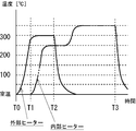
- FIG. 7 is a time chart showing the operating states of the external heater 35 and the internal heater 36 during the heating control of the heater 3 executed by the controller 4.
- FIG. 8 is a diagram for explaining changes in the surface temperature of the external heater 35 and the internal heater 36 during heating control.
- time T0 represents the timing at which the controller 4 detects the ON operation of the operation button of the non-combustion heating type smoking device 1 (hereinafter, referred to as “heating start timing”).
- the controller 4 starts power supply from the power source 5 only to the external heater 35.
- the controller 4 starts the power supply from the power source 5 to the internal heater 36 while continuing the power supply from the power source 5 to the external heater 35.
- the time T1 is referred to as "internal heating start timing”.
- the controller 4 stops the power supply from the power source 5 to the external heater 35 while continuing the power supply from the power source 5 to the internal heater 36.
- the time T2 is referred to as “external heating stop timing”. Then, at a time T3 when a predetermined smoking time has elapsed from the time T0 (heating start timing), the power supply from the power source 5 to the internal heater 36 is stopped.
- the time T3 is referred to as “heating stop timing”.
- the non-combustion heating type smoking device 1 in the present embodiment preheats the tobacco rod 11 (initial heating) by operating only the external heater 35 at the heating start timing when heating of the tobacco rod 11 is started.
- the external heater 35 is provided along the cavity side peripheral wall 32 located on the outer peripheral portion (side surface) of the accommodation cavity 34, the outer peripheral portion of the tobacco rod 11 accommodated in the accommodation cavity 34 is efficiently disposed. Can be heated to. That is, the heating of the tobacco rod 11 by the internal heater 36 at time T1 (internal heating start timing) can be efficiently preheated, particularly the outer peripheral portion of the tobacco rod 11.
- a period from time T0 (heating start timing) to time T1 (internal heater start timing) is referred to as a “preheating period”.
- the preheating period can be set as the time when the elapsed time has reached a predetermined set time from the heating start timing (that is, preheat start) or the temperature of the external heater 35 has reached the predetermined set temperature.
- the controller 4 may set the set temperature for controlling the external heater 35 to 300°C.
- the time elapsed from the heating start timing reaches a predetermined set time, or the temperature of the external heater 35 reaches a predetermined set temperature, that is, time T1 (internal heating start timing) to time T2 (external heating stop).
- the tobacco rod 11 is heated by both the external heater 35 and the internal heater 36.
- the internal heater 36 is arranged coaxially with the central axis CL1 of the housing cavity 34. Therefore, the heat of the internal heater 36 penetrating the tobacco rod 11 (filler 111) is radially transferred from the center side of the tobacco rod 11 toward the outer peripheral side.
- the tobacco rod 11 can be efficiently heated, the aerosol-generating base material (eg, glycerin, etc.) contained in the filler 111 of the tobacco rod 11 and the flavor component contained in the tobacco cut are volatilized in a short time, An aerosol can be generated that includes a flavor component.
- the aerosol-generating base material eg, glycerin, etc.
- the filling material 111 of the tobacco rod 11 including the aerosol-forming base material eg, glycerin
- the aerosol-forming base material eg, glycerin
- the aerosol-forming base material eg, glycerin
- the controller 4 controls the temperature of the external heater 35 to be higher than the temperature of the internal heater 36.
- the controller 4 controls the external heater 35 and the internal heater 36 by setting the set temperature of the external heater 35 to 300° C. and the set temperature of the internal heater 36 to 250° C.
- the outer peripheral portion of the tobacco rod 11 is rapidly and efficiently heated by the external heater 35 that is in contact with or close to the outer peripheral portion, and even during the subsequent simultaneous heating period.
- the temperature of the heater 35 is controlled to be higher than that of the internal heater 36.
- the distance from the internal heater 36 makes it difficult for the heat of the internal heater 36 to reach, and the outer peripheral portion of the tobacco rod 11 can be positively heated due to the influence of the outside air (heat dissipation loss). .. That is, the center side of the cross section of the tobacco rod 11 is efficiently heated by the internal heater 36, the heat of the internal heater 36 is hard to be transferred, and the outer peripheral portion of the tobacco rod 11 is easily affected by the outside air (heat dissipation loss). Can be heated efficiently. As a result, the entire tobacco rod 11 can be uniformly heated to a temperature at which the aerosol-generating substrate is sufficiently volatilized.
- the tobacco rod 11 is heated only by the external heater 35, and the internal heater 36 is operated after the preheating period elapses after the operation of the external heater 35, so that the external heater 35 and the internal heater 36 are operated in the preheating period. It is possible to reduce the total power consumption as compared with the case where both of them are operated.
- the aerosol-generating base material that has once volatilized is condensed (condensation) on the outer peripheral portion of the tobacco rod 11. /Liquefaction) can be suppressed. Therefore, in particular, the delivery amount of the aerosol at the time of initial smoking can be sufficiently secured, and the feeling of smoke amount can be improved.
- the external heater 35 includes the external end of the tobacco rod 11 housed in the housing cavity 34 (on the mouthpiece portion 12 side). ) Is located. Therefore, of the outer peripheral portion of the tobacco rod 11, particularly the region on the base end side can be intensively heated by the external heater 35. According to this, there is an advantage that the aerosol generated on the tip side (upstream side) of the tobacco rod 11 can be effectively suppressed from condensing on the base end side (downstream side) of the tobacco rod 11.
- the external heater width dimension which is the length of the external heater 35 extending along the central axis CL1 direction of the accommodation cavity 34, is preferably at least one third or more of the tobacco rod 11. According to this, prior to the start of heating by the internal heater 36, the outer peripheral portion of the tobacco rod 11 can be sufficiently preheated during the preheating period of the tobacco rod 11.
- the temperature of the tobacco rod 11 can be maintained at a temperature at which the aerosol does not condense only by heating by the internal heater 36, and thus the external heating is performed.
- the stop timing time T2
- the controller 4 stops the operation of the external heater 35.
- the controller 4 stops the operation of the external heater 35 before the temperature of the internal heater 36 exceeds the temperature of the external heater 35.
- the external heating stop timing (time T2) for stopping the operation of the external heater 35 reaches a predetermined set time from the heating start timing (that is, preheating start), or the external heater 35 temperature is It can be set as the time when the predetermined set temperature is reached.
- the operation of the external heater 35 may be stopped when a certain time has elapsed since the temperature of the external heater 35 reached a predetermined set temperature, and various modes can be adopted. ..
- the internal heater 36 arranged in the central portion is superior to the external heater 35 arranged on the outer peripheral side of the accommodation cavity 34 in heating efficiency when heating the tobacco rod 11. Therefore, the tobacco rod 11 is heated only by the internal heater 36 having excellent heating efficiency during the rest of the smoking period when the conditions in which the condensation of the aerosol is unlikely to occur are sufficiently raised by sufficiently heating the entire tobacco rod 11 in the simultaneous heating period. By doing so, the aerosol can be generated stably and continuously.
- the controller 4 may control the power supply from the power source 5 to the internal heater 36 after the operation of the external heater 35 is stopped so that the temperature of the internal heater 36 is increased as compared to before the operation of the external heater 35 is stopped. ..
- the controller 4 may change the set temperature of the internal heater 36 from 250°C to 350°C.
- the set temperature of the internal heater 36 during the internal heating period may be set to an appropriate temperature at which the aerosol-generating substrate contained in the tobacco rod 11 can be volatilized stably and continuously by heating only the internal heater 36. preferable.
- the set temperature of the internal heater 36 is raised after the operation of the external heater 35 is stopped, the power consumption of the internal heater 36 increases, but the operation of the external heater 35 is stopped. It is possible to reduce the total power consumption.
- the controller 4 stops the power supply from the power source 5 to the internal heater 36.
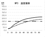
- FIG. 9 to 12 show the results of the temperature measurement test in which changes in the surface temperature of the external heater 35, the surface temperature of the internal heater 36, and the product temperature of the tobacco rod 11 were measured when the heating control of the heater 3 was performed by the controller 4.
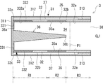
- FIG. FIG. 13 is a diagram showing the product temperature measurement position of the tobacco rod 11.
- the temperature of the tobacco rod 11 was measured from the first measurement position MP1 to the third measurement position MP3 shown in FIG.
- the distance from the measurement positions MP1 to MP3 in the radial direction of the accommodation cavity 34 to the side peripheral surface of the accommodation cavity 34 (the inner peripheral surface 32a of the cavity side peripheral wall 32) was set to 1.5 mm.
- the distance between the measurement positions MP1 to MP3 in the radial direction of the housing cavity 34 and the base end portion 36a of the internal heater 36 was set to 1.5 mm.
- the first measurement position MP1 to the third measurement position MP3 are arranged in order of the first measurement position MP1, the second measurement position MP2, and the third measurement position MP3 from the cavity bottom 331 side.
- the space between the cavity bottom 331 and the first measurement position MP1 was set to 2 mm.
- the distance between the first measurement position MP1 and the second measurement position MP2 was set to 5 mm.
- the distance between the second measurement position MP2 and the third measurement position MP3 was 6 mm.
- the distance between the third measurement position MP3 and the retracted rod rear end position P1 was set to 2 mm.
- the elapsed time from the heating start timing to the internal heater start timing is set to 6 seconds
- the elapsed time from the heating start timing to the external heating stop timing is set to 20 seconds
- heating is stopped from the heating start timing.
- the elapsed time until the timing was set to 420 seconds.
- the temperature transitions indicated by the solid lines are the temperature transitions at the respective measurement positions MP1 to MP3 when the heating control according to the present embodiment described in FIGS. (Referred to as “example”).
- the temperature change indicated by the broken line indicates the temperature change at each measurement position MP1 to MP3 (hereinafter referred to as “comparative example”) when the heating control is performed using only the internal heater 36 without using the external heater.
- the two-dot chain line shown in FIGS. 10 to 12 is the target product temperature when heating the tobacco rod 11.
- the target product temperature is, for example, 150°C.
- the example and the comparative example are compared during heating control. There was no significant difference between the two. Since the first measurement position MP1 and the second measurement position MP2 are both far from the external heater 35 and relatively close to the internal heater 36, it is considered that the influence of the external heater 35 was small. On the other hand, as shown in FIG. 12, at the third measurement position MP3, a remarkable difference appears between the example and the comparative example, and the example raises the target product temperature in a shorter time than the comparative example. It was possible to raise the temperature, and the superiority of the example to the comparative example could be confirmed.
- the internal heater 36 which is disposed in the accommodation cavity 34 and volatilizes the aerosol-generating substrate by heating the tobacco rod 11 from the inside.
- an external part for suppressing the condensation of aerosol generated during the operation of the internal heater 36 which is arranged on the side peripheral part of the storage cavity 34 and preheats at least the outer peripheral part of the tobacco rod 11 during the preheating period of the tobacco rod 11.
- a heater 35 This makes it possible to sufficiently heat the outer peripheral portion of the tobacco rod 11 in advance in the preheating period by the external heater, in which heat is difficult to reach from the internal heater and the influence of the outside air (heat dissipation loss) is likely to occur. As a result, it is possible to suppress the condensation of the aerosol generated when the internal heater 36 is activated. Therefore, it is possible to secure a sufficient amount of aerosol delivered during smoking, and to improve the feeling of smoke volume.
- the external heater 35 is arranged in the first region R1 including the base end 32c of the cavity side peripheral wall 32 (side peripheral portion) where the cavity bottom 331 is provided and the third region R3 including the insertion port 38.
- the external heater 35 is arranged in the second region R2 located closer to the insertion opening 38 side than the first region R1, so that the region of the outer peripheral portion of the tobacco rod 11, particularly on the proximal end side, is covered by the external heater 35. It can be heated intensively. Thereby, it is possible to effectively suppress the condensation of the aerosol generated on the tip end side (upstream side) of the tobacco rod 11 on the base end side (downstream side) of the tobacco rod 11.
- the internal heater 36 in the present embodiment has a tapered shape in which the diameter decreases from the base end portion 36a side toward the tip end portion 36b side, the tip end portion 36b of the internal heater 36 is smaller than the base end side.
- the amount of heat radiated to the tobacco rod 11 tends to decrease, by arranging the external heater 35 around the tip portion 36b of the internal heater 36 (a position corresponding to the tip portion 36b of the internal heater 36), The shortage of the amount of heat radiation at the tip portion 36b can be appropriately compensated.
- the external heater 35 in the first region R1 where the amount of heat radiated from the internal heater 36 can be sufficiently ensured, the power consumption of the power source 5 is suppressed, and the base end region in the outer peripheral portion of the tobacco rod 11 is kept outside. It can be efficiently heated by the heater 35.
- the external heater 35 is not arranged in the third region R3 of the cavity side peripheral wall 32 (side peripheral portion), when the external heater 35 is operated, the front end portion of the mouthpiece portion 12 is activated. It is possible to prevent the filter segment, which is located at, for example, from being burnt or melted by the heat of the external heater 35.
- the internal heater 36 is a truncated cone shape, but the internal heater 36 having a tapered shape from the cavity bottom 331 side toward the insertion port 38 side is adopted as described above.
- the internal heater 36 can easily penetrate the filler 111 of the tobacco rod 11 inserted into the storage cavity 34.
- the contact state between the internal heater 36 and the filling 111 can be maintained well.
- the heat generated by the internal heater 36 is easily transmitted to the filling material 111, and the heating efficiency of the filling material 111 can be improved.
- the internal heater 36 is inserted into the filler 111 of the tobacco rod 11 that is inserted into the storage cavity 34, but the end surface of the filler 111 on the leading end side (upstream side) of the tobacco rod 11 is inserted.
- the internal heater 36 may be inserted in the formed recess.
- the internal heater 36 can adopt various shapes.
- the internal heater 36 may have a truncated cone shape or a truncated cone shape, and may have a tapered shape from the cavity bottom 331 side toward the insertion port 38 side.
- a conical shape may be used instead of the truncated cone shape.
- the internal heater 36 may have a columnar shape. In this case, a conical portion may be formed on the tip side of the cylindrical portion of the internal heater 36.
- the internal heater 36 has n-fold symmetry with respect to the central axis CL1 of the housing cavity 34, and n may be an integer of 3 or more.
- the tip portion 36b of the internal heater 36 of the heater 3 corresponds to the tip of the second region R2 (end portion on the insertion opening 38 side) of the cavity side peripheral wall 32 (side peripheral portion).
- the present invention is not limited to this.
- the tip portion 36b of the internal heater 36 may be arranged at a position corresponding to the middle portion of the second region R2.
- the tip portion 36b of the internal heater 36 may be arranged at a position corresponding to the third region R3.
- the tip portion 36b of the internal heater 36 may be arranged at a position corresponding to the first region R1.
- the non-combustion heating type smoking device according to the present invention is not limited to these, and these can be combined as much as possible.
- Non-combustion heating type smoking device 2 For Housing 3
- Heater 4 for Controller 5
- Power source 10 for Non-combustion heating type smoking article 11
- Tobacco rod 12 for Tobacco rod 12
Landscapes
- Resistance Heating (AREA)
- Cigarettes, Filters, And Manufacturing Of Filters (AREA)
Abstract
Description
図1は、実施形態1に係る非燃焼加熱型喫煙装置1の内部構造を概略的に示す図である。非燃焼加熱型喫煙装置1は、各種構成部品を収容するための筐体であるハウジング2を有する。ハウジング2内には、加熱器3、コントローラ(制御部)4、電源5等が収容されている。
そして、時間T1において、コントローラ4は、電源5から外部ヒーター35への電力供給を継続しつつ、電源5から内部ヒーター36に対する電力供給を開始させる。以下、時間T1を「内部加熱開始タイミング」という。そして、時間T2において、コントローラ4は、電源5から内部ヒーター36に対する電力供給を継続しつつ、電源5から外部ヒーター35に対する電力供給を停止させる。以下、時間T2を「外部加熱停止タイミング」という。そして、時間T0(加熱開始タイミング)から所定の喫煙時間が経過した時間T3において、電源5から内部ヒーター36に対する電力供給を停止させる。以下、時間T3を「加熱停止タイミング」という。
2・・・ハウジング
3・・・加熱器
4・・・コントローラ
5・・・電源
10・・・非燃焼加熱型喫煙物品
11・・・たばこロッド
12・・・マウスピース部
34・・・収容キャビティ
35・・・外部ヒーター
36・・・内部ヒーター
Claims (13)
- たばこ刻み及びエアロゾル生成基材を含むたばこロッドを収容するための収容キャビティと、
前記収容キャビティ内に配置され、前記収容キャビティに挿入されるたばこロッドに貫入または当該たばこロッドの端面に形成された凹部に挿入するための内部ヒーターであって、前記たばこロッドを内側から加熱することで前記エアロゾル生成基材を揮発させるための内部ヒーターと、
前記収容キャビティの側周部に配置され、少なくとも前記たばこロッドの予熱期間に前記たばこロッドの外周部を予熱することで、前記内部ヒーターの作動時に発生したエアロゾルの凝縮を抑制するための外部ヒーターと、
を備える、
非燃焼加熱型喫煙装置。 - 前記内部ヒーター及び前記外部ヒーターを制御する制御部を備え、
前記制御部は、前記内部ヒーター及び前記外部ヒーターの双方が作動する同時加熱期間において、前記外部ヒーターの温度が前記内部ヒーターの温度より高くなるように制御する、
請求項1に記載の非燃焼加熱型喫煙装置。 - 前記制御部は、前記外部ヒーターによる前記たばこロッドの予熱開始からの経過時間が所定の設定時間に到達し、または前記外部ヒーターの温度が所定の設定温度に到達した時点で当該外部ヒーターの作動を停止させるが、前記内部ヒーターの作動を継続させる、
請求項2に記載の非燃焼加熱型喫煙装置。 - 前記制御部は、前記外部ヒーターの作動停止後、前記内部ヒーターの温度を前記外部ヒーターの作動停止前に比べて増加させる、
請求項3に記載の非燃焼加熱型喫煙装置。 - 前記制御部は、前記たばこロッドの予熱を開始する際に前記外部ヒーターのみを作動させることで当該予熱を開始し、前記外部ヒーターの作動に遅れて前記内部ヒーターを作動させる、
請求項2から4の何れか一項に記載の非燃焼加熱型喫煙装置。 - 前記収容キャビティは、前記側周部の先端側に位置すると共に前記たばこロッドを挿入可能に開放された開放端である挿入口と、前記側周部における基端側に位置するキャビティ底部と、を有し、
前記側周部は、前記キャビティ底部が設けられる基端を含む第1領域と、前記第1領域に隣接して前記挿入口側に位置する第2領域と、を有し、
前記外部ヒーターは、前記第1領域に配置されておらず且つ前記第2領域に配置されている、
請求項1から5の何れか一項に記載の非燃焼加熱型喫煙装置。 - 前記外部ヒーターは、前記第2領域における一部の区間または全区間において前記側周部の周方向に沿って全周に亘って配置されている、
請求項6に記載の非燃焼加熱型喫煙装置。 - 前記内部ヒーターは、前記収容キャビティの中心軸に対してn回対称性を有し、nは3以上の整数である、
請求項6または7に記載の非燃焼加熱型喫煙装置。 - 前記内部ヒーターは円柱形状を有し、且つ、先端側に円錐部が形成されている、請求項6から8の何れか一項に記載の非燃焼加熱型喫煙装置。
- 前記内部ヒーターは錐形状または錐台形状を有し、且つ、前記キャビティ底部側から前記挿入口側に向かって先細り形状となっている、請求項6から8の何れか一項に記載の非燃焼加熱型喫煙装置。
- 前記内部ヒーターは円錐形状または円錐台形状を有する、請求項6から8の何れか一項に記載の非燃焼加熱型喫煙装置。
- 前記側周部は、前記第2領域に隣接すると共に前記挿入口を含む第3領域を更に有し、当該第3領域には前記外部ヒーターが配置されていない、請求項6から11の何れか一項に記載の非燃焼加熱型喫煙装置。
- 前記内部ヒーターの先端位置は、前記側周部における前記第2領域または前記第3領域に対応付けられている、請求項12に記載の非燃焼加熱型喫煙装置。
Priority Applications (6)
| Application Number | Priority Date | Filing Date | Title |
|---|---|---|---|
| JP2020558811A JP7140841B2 (ja) | 2018-12-10 | 2018-12-10 | 非燃焼加熱型喫煙装置 |
| PCT/JP2018/045294 WO2020121374A1 (ja) | 2018-12-10 | 2018-12-10 | 非燃焼加熱型喫煙装置 |
| EP18942739.6A EP3895561B1 (en) | 2018-12-10 | 2018-12-10 | Non-combustible heating-type smoking device |
| PL18942739.6T PL3895561T3 (pl) | 2018-12-10 | 2018-12-10 | Niespalające, ogrzewające urządzenie do palenia |
| CN201880100110.1A CN113163869B (zh) | 2018-12-10 | 2018-12-10 | 非燃烧加热型吸烟装置 |
| JP2022143141A JP7315766B2 (ja) | 2018-12-10 | 2022-09-08 | 非燃焼加熱型喫煙装置 |
Applications Claiming Priority (1)
| Application Number | Priority Date | Filing Date | Title |
|---|---|---|---|
| PCT/JP2018/045294 WO2020121374A1 (ja) | 2018-12-10 | 2018-12-10 | 非燃焼加熱型喫煙装置 |
Publications (1)
| Publication Number | Publication Date |
|---|---|
| WO2020121374A1 true WO2020121374A1 (ja) | 2020-06-18 |
Family
ID=71076809
Family Applications (1)
| Application Number | Title | Priority Date | Filing Date |
|---|---|---|---|
| PCT/JP2018/045294 Ceased WO2020121374A1 (ja) | 2018-12-10 | 2018-12-10 | 非燃焼加熱型喫煙装置 |
Country Status (5)
| Country | Link |
|---|---|
| EP (1) | EP3895561B1 (ja) |
| JP (1) | JP7140841B2 (ja) |
| CN (1) | CN113163869B (ja) |
| PL (1) | PL3895561T3 (ja) |
| WO (1) | WO2020121374A1 (ja) |
Cited By (6)
| Publication number | Priority date | Publication date | Assignee | Title |
|---|---|---|---|---|
| CN112471601A (zh) * | 2020-11-27 | 2021-03-12 | 上海烟草集团有限责任公司 | 多段温控方法、多段加热设备及计算机可读存储介质 |
| CN113100495A (zh) * | 2021-04-09 | 2021-07-13 | 福建中烟工业有限责任公司 | 电子烟及其控制方法、控制器和气溶胶生成装置 |
| US20230240367A1 (en) * | 2020-06-26 | 2023-08-03 | Nicoventures Trading Limited | Apparatus for heating aersolisable material |
| JP2024521971A (ja) * | 2021-06-18 | 2024-06-04 | ニコベンチャーズ トレーディング リミテッド | エアロゾル生成デバイス |
| JP2025504782A (ja) * | 2022-01-26 | 2025-02-19 | ニコベンチャーズ トレーディング リミテッド | 電子蒸気供給システム及び方法 |
| EP4272588B1 (en) | 2022-05-04 | 2025-04-23 | JT International SA | Heating method for a flat-shaped heating chamber of an aerosol generating device and associated aerosol generating device |
Families Citing this family (3)
| Publication number | Priority date | Publication date | Assignee | Title |
|---|---|---|---|---|
| EP3957199A4 (en) * | 2019-04-18 | 2022-12-14 | Japan Tobacco Inc. | HEATED TOBACCO PRODUCT |
| KR102915809B1 (ko) * | 2022-02-09 | 2026-01-22 | 주식회사 케이티앤지 | 에어로졸 발생 물품 및 에어로졸 발생 시스템 |
| GB202215593D0 (en) * | 2022-10-21 | 2022-12-07 | Nicoventures Trading Ltd | Aerosol provision device |
Citations (11)
| Publication number | Priority date | Publication date | Assignee | Title |
|---|---|---|---|---|
| JP3976345B2 (ja) * | 1996-10-22 | 2007-09-19 | フイリップ モーリス プロダクツ インコーポレイテッド | 電気喫煙システムを作動させる電力制御器及びその方法 |
| JP2010520742A (ja) * | 2006-08-03 | 2010-06-17 | ブリティッシュ・アメリカン・タバコ・ジャパン合同会社 | 揮発装置 |
| JP2012527222A (ja) * | 2009-05-21 | 2012-11-08 | フィリップ・モーリス・プロダクツ・ソシエテ・アノニム | 電気加熱式喫煙システム |
| JP2013511962A (ja) | 2009-11-27 | 2013-04-11 | フィリップ・モーリス・プロダクツ・ソシエテ・アノニム | 内部又は外部ヒータを備える電気加熱式喫煙システム |
| CN203748672U (zh) * | 2013-12-30 | 2014-08-06 | 深圳市合元科技有限公司 | 电子烟用雾化器及电子烟 |
| JP2014525251A (ja) | 2011-09-06 | 2014-09-29 | ブリティッシュ アメリカン タバコ (インヴェストメンツ) リミテッド | 喫煙材の加熱 |
| JP2015506170A (ja) * | 2011-12-30 | 2015-03-02 | フィリップ・モーリス・プロダクツ・ソシエテ・アノニム | 温度分布が改善されたエアロゾル発生装置 |
| CN104799438A (zh) * | 2015-04-30 | 2015-07-29 | 云南昆船数码科技有限公司 | 一种低温加热电子卷烟烟具发热器 |
| JP2017503499A (ja) * | 2013-12-31 | 2017-02-02 | フィリップ・モーリス・プロダクツ・ソシエテ・アノニム | エアロゾル発生装置、およびエアロゾル発生装置で使用するためのカプセル |
| US20170273357A1 (en) * | 2016-03-23 | 2017-09-28 | Elise Barbuck | Vaporizer Adapter For a Rolled Article |
| JP2018512142A (ja) * | 2015-03-31 | 2018-05-17 | ブリティッシュ アメリカン タバコ (インヴェストメンツ) リミテッドBritish American Tobacco (Investments) Limited | 喫煙材を加熱するための装置、それに使用する物品および物品の製造方法 |
Family Cites Families (2)
| Publication number | Priority date | Publication date | Assignee | Title |
|---|---|---|---|---|
| JP6686157B2 (ja) * | 2016-10-12 | 2020-04-22 | 日本たばこ産業株式会社 | 香味吸引器 |
| KR102199794B1 (ko) * | 2018-11-16 | 2021-01-07 | 주식회사 케이티앤지 | 연속사용이 가능한 에어로졸 생성장치의 히터의 전력을 제어하는 방법 및 그 에어로졸 생성장치 |
-
2018
- 2018-12-10 JP JP2020558811A patent/JP7140841B2/ja active Active
- 2018-12-10 WO PCT/JP2018/045294 patent/WO2020121374A1/ja not_active Ceased
- 2018-12-10 PL PL18942739.6T patent/PL3895561T3/pl unknown
- 2018-12-10 EP EP18942739.6A patent/EP3895561B1/en active Active
- 2018-12-10 CN CN201880100110.1A patent/CN113163869B/zh active Active
Patent Citations (12)
| Publication number | Priority date | Publication date | Assignee | Title |
|---|---|---|---|---|
| JP3976345B2 (ja) * | 1996-10-22 | 2007-09-19 | フイリップ モーリス プロダクツ インコーポレイテッド | 電気喫煙システムを作動させる電力制御器及びその方法 |
| JP2010520742A (ja) * | 2006-08-03 | 2010-06-17 | ブリティッシュ・アメリカン・タバコ・ジャパン合同会社 | 揮発装置 |
| JP2012527222A (ja) * | 2009-05-21 | 2012-11-08 | フィリップ・モーリス・プロダクツ・ソシエテ・アノニム | 電気加熱式喫煙システム |
| JP2013511962A (ja) | 2009-11-27 | 2013-04-11 | フィリップ・モーリス・プロダクツ・ソシエテ・アノニム | 内部又は外部ヒータを備える電気加熱式喫煙システム |
| JP2014525251A (ja) | 2011-09-06 | 2014-09-29 | ブリティッシュ アメリカン タバコ (インヴェストメンツ) リミテッド | 喫煙材の加熱 |
| JP2015506170A (ja) * | 2011-12-30 | 2015-03-02 | フィリップ・モーリス・プロダクツ・ソシエテ・アノニム | 温度分布が改善されたエアロゾル発生装置 |
| JP6026556B2 (ja) | 2011-12-30 | 2016-11-16 | フィリップ・モーリス・プロダクツ・ソシエテ・アノニム | 温度分布が改善されたエアロゾル発生装置 |
| CN203748672U (zh) * | 2013-12-30 | 2014-08-06 | 深圳市合元科技有限公司 | 电子烟用雾化器及电子烟 |
| JP2017503499A (ja) * | 2013-12-31 | 2017-02-02 | フィリップ・モーリス・プロダクツ・ソシエテ・アノニム | エアロゾル発生装置、およびエアロゾル発生装置で使用するためのカプセル |
| JP2018512142A (ja) * | 2015-03-31 | 2018-05-17 | ブリティッシュ アメリカン タバコ (インヴェストメンツ) リミテッドBritish American Tobacco (Investments) Limited | 喫煙材を加熱するための装置、それに使用する物品および物品の製造方法 |
| CN104799438A (zh) * | 2015-04-30 | 2015-07-29 | 云南昆船数码科技有限公司 | 一种低温加热电子卷烟烟具发热器 |
| US20170273357A1 (en) * | 2016-03-23 | 2017-09-28 | Elise Barbuck | Vaporizer Adapter For a Rolled Article |
Non-Patent Citations (1)
| Title |
|---|
| See also references of EP3895561A4 |
Cited By (8)
| Publication number | Priority date | Publication date | Assignee | Title |
|---|---|---|---|---|
| US20230240367A1 (en) * | 2020-06-26 | 2023-08-03 | Nicoventures Trading Limited | Apparatus for heating aersolisable material |
| CN112471601A (zh) * | 2020-11-27 | 2021-03-12 | 上海烟草集团有限责任公司 | 多段温控方法、多段加热设备及计算机可读存储介质 |
| CN113100495A (zh) * | 2021-04-09 | 2021-07-13 | 福建中烟工业有限责任公司 | 电子烟及其控制方法、控制器和气溶胶生成装置 |
| JP2024521971A (ja) * | 2021-06-18 | 2024-06-04 | ニコベンチャーズ トレーディング リミテッド | エアロゾル生成デバイス |
| JP7796146B2 (ja) | 2021-06-18 | 2026-01-08 | ニコベンチャーズ トレーディング リミテッド | エアロゾル生成デバイス |
| JP2025504782A (ja) * | 2022-01-26 | 2025-02-19 | ニコベンチャーズ トレーディング リミテッド | 電子蒸気供給システム及び方法 |
| JP7821889B2 (ja) | 2022-01-26 | 2026-02-27 | ニコベンチャーズ トレーディング リミテッド | 電子蒸気供給システム及び方法 |
| EP4272588B1 (en) | 2022-05-04 | 2025-04-23 | JT International SA | Heating method for a flat-shaped heating chamber of an aerosol generating device and associated aerosol generating device |
Also Published As
| Publication number | Publication date |
|---|---|
| CN113163869A (zh) | 2021-07-23 |
| EP3895561B1 (en) | 2024-10-09 |
| EP3895561A4 (en) | 2022-08-03 |
| EP3895561C0 (en) | 2024-10-09 |
| EP3895561A1 (en) | 2021-10-20 |
| PL3895561T3 (pl) | 2025-02-10 |
| JPWO2020121374A1 (ja) | 2021-10-28 |
| JP7140841B2 (ja) | 2022-09-21 |
| CN113163869B (zh) | 2025-02-11 |
Similar Documents
| Publication | Publication Date | Title |
|---|---|---|
| JP7140841B2 (ja) | 非燃焼加熱型喫煙装置 | |
| JP7623422B2 (ja) | 制御ユニット、エアロゾル生成装置、ヒータを制御する方法及びプログラム、並びに喫煙物品 | |
| EP3818872B1 (en) | Aerosol generation device having first heater and second heater, and method for controlling power to first heater and second heater of aerosol generation device | |
| JP7086859B2 (ja) | 加熱式エアロゾル発生物品を備えるエアロゾル発生システム | |
| JP7601995B2 (ja) | 積層ラッパーを備えるエアロゾル発生物品 | |
| JP6584447B2 (ja) | 喫煙材の加熱 | |
| JP6176737B2 (ja) | 物質を蒸発させるための方法とシステム | |
| EP3760060A1 (en) | Aerosol generating systems | |
| KR20210021291A (ko) | 에어로졸 발생 기재의 중공형 로드를 포함하는 에어로졸 발생 물품 | |
| EA036871B1 (ru) | Способ работы электронного парового ингалятора | |
| TW202015564A (zh) | 控制單元、霧氣生成裝置、控制加熱器之方法及程式以及吸煙物品 | |
| JP2024539888A (ja) | エアロゾル供給デバイス | |
| CN118265467A (zh) | 气溶胶供应装置 | |
| JP7315766B2 (ja) | 非燃焼加熱型喫煙装置 | |
| KR20230047142A (ko) | 플라워 스틱용 이중 대류 및 전도 오븐 | |
| JP2025106617A (ja) | 加熱デバイスおよび加熱システム | |
| TW202021488A (zh) | 非燃燒加熱型吸煙裝置 | |
| RU2775629C1 (ru) | Негорючее нагревательное курительное устройство | |
| EP4051030B1 (en) | Aerosol generating device and system | |
| WO2023148915A1 (ja) | 喫煙システムおよび香味吸引器 | |
| CN116075242A (zh) | 气溶胶产生制品 |
Legal Events
| Date | Code | Title | Description |
|---|---|---|---|
| 121 | Ep: the epo has been informed by wipo that ep was designated in this application |
Ref document number: 18942739 Country of ref document: EP Kind code of ref document: A1 |
|
| ENP | Entry into the national phase |
Ref document number: 2020558811 Country of ref document: JP Kind code of ref document: A |
|
| NENP | Non-entry into the national phase |
Ref country code: DE |
|
| ENP | Entry into the national phase |
Ref document number: 2018942739 Country of ref document: EP Effective date: 20210712 |
|
| WWG | Wipo information: grant in national office |
Ref document number: 201880100110.1 Country of ref document: CN |