WO2020121671A1 - モータ一体型流体機械及び垂直離着陸機 - Google Patents
モータ一体型流体機械及び垂直離着陸機 Download PDFInfo
- Publication number
- WO2020121671A1 WO2020121671A1 PCT/JP2019/042502 JP2019042502W WO2020121671A1 WO 2020121671 A1 WO2020121671 A1 WO 2020121671A1 JP 2019042502 W JP2019042502 W JP 2019042502W WO 2020121671 A1 WO2020121671 A1 WO 2020121671A1
- Authority
- WO
- WIPO (PCT)
- Prior art keywords
- rotating
- motor
- shaft
- rotation
- outer peripheral
- Prior art date
- Legal status (The legal status is an assumption and is not a legal conclusion. Google has not performed a legal analysis and makes no representation as to the accuracy of the status listed.)
- Ceased
Links
Images


Classifications
-
- H—ELECTRICITY
- H02—GENERATION; CONVERSION OR DISTRIBUTION OF ELECTRIC POWER
- H02K—DYNAMO-ELECTRIC MACHINES
- H02K7/00—Arrangements for handling mechanical energy structurally associated with dynamo-electric machines, e.g. structural association with mechanical driving motors or auxiliary dynamo-electric machines
- H02K7/14—Structural association with mechanical loads, e.g. with hand-held machine tools or fans
-
- B—PERFORMING OPERATIONS; TRANSPORTING
- B64—AIRCRAFT; AVIATION; COSMONAUTICS
- B64C—AEROPLANES; HELICOPTERS
- B64C11/00—Propellers, e.g. of ducted type; Features common to propellers and rotors for rotorcraft
- B64C11/001—Shrouded propellers
-
- B—PERFORMING OPERATIONS; TRANSPORTING
- B64—AIRCRAFT; AVIATION; COSMONAUTICS
- B64C—AEROPLANES; HELICOPTERS
- B64C11/00—Propellers, e.g. of ducted type; Features common to propellers and rotors for rotorcraft
- B64C11/02—Hub construction
- B64C11/04—Blade mountings
- B64C11/08—Blade mountings for non-adjustable blades
- B64C11/10—Blade mountings for non-adjustable blades rigid
-
- B—PERFORMING OPERATIONS; TRANSPORTING
- B64—AIRCRAFT; AVIATION; COSMONAUTICS
- B64C—AEROPLANES; HELICOPTERS
- B64C27/00—Rotorcraft; Rotors peculiar thereto
- B64C27/04—Helicopters
-
- B—PERFORMING OPERATIONS; TRANSPORTING
- B64—AIRCRAFT; AVIATION; COSMONAUTICS
- B64C—AEROPLANES; HELICOPTERS
- B64C29/00—Aircraft capable of landing or taking-off vertically, e.g. vertical take-off and landing [VTOL] aircraft
-
- B—PERFORMING OPERATIONS; TRANSPORTING
- B64—AIRCRAFT; AVIATION; COSMONAUTICS
- B64D—EQUIPMENT FOR FITTING IN OR TO AIRCRAFT; FLIGHT SUITS; PARACHUTES; ARRANGEMENT OR MOUNTING OF POWER PLANTS OR PROPULSION TRANSMISSIONS IN AIRCRAFT
- B64D27/00—Arrangement or mounting of power plants in aircraft; Aircraft characterised by the type or position of power plants
- B64D27/02—Aircraft characterised by the type or position of power plants
- B64D27/30—Aircraft characterised by electric power plants
- B64D27/34—All-electric aircraft
-
- B—PERFORMING OPERATIONS; TRANSPORTING
- B64—AIRCRAFT; AVIATION; COSMONAUTICS
- B64U—UNMANNED AERIAL VEHICLES [UAV]; EQUIPMENT THEREFOR
- B64U30/00—Means for producing lift; Empennages; Arrangements thereof
- B64U30/20—Rotors; Rotor supports
- B64U30/29—Constructional aspects of rotors or rotor supports; Arrangements thereof
-
- B—PERFORMING OPERATIONS; TRANSPORTING
- B64—AIRCRAFT; AVIATION; COSMONAUTICS
- B64U—UNMANNED AERIAL VEHICLES [UAV]; EQUIPMENT THEREFOR
- B64U50/00—Propulsion; Power supply
- B64U50/10—Propulsion
- B64U50/13—Propulsion using external fans or propellers
- B64U50/14—Propulsion using external fans or propellers ducted or shrouded
-
- B—PERFORMING OPERATIONS; TRANSPORTING
- B64—AIRCRAFT; AVIATION; COSMONAUTICS
- B64U—UNMANNED AERIAL VEHICLES [UAV]; EQUIPMENT THEREFOR
- B64U50/00—Propulsion; Power supply
- B64U50/10—Propulsion
- B64U50/19—Propulsion using electrically powered motors
-
- H—ELECTRICITY
- H02—GENERATION; CONVERSION OR DISTRIBUTION OF ELECTRIC POWER
- H02K—DYNAMO-ELECTRIC MACHINES
- H02K21/00—Synchronous motors having permanent magnets; Synchronous generators having permanent magnets
- H02K21/12—Synchronous motors having permanent magnets; Synchronous generators having permanent magnets with stationary armatures and rotating magnets
- H02K21/24—Synchronous motors having permanent magnets; Synchronous generators having permanent magnets with stationary armatures and rotating magnets with magnets axially facing the armatures, e.g. hub-type cycle dynamos
-
- Y—GENERAL TAGGING OF NEW TECHNOLOGICAL DEVELOPMENTS; GENERAL TAGGING OF CROSS-SECTIONAL TECHNOLOGIES SPANNING OVER SEVERAL SECTIONS OF THE IPC; TECHNICAL SUBJECTS COVERED BY FORMER USPC CROSS-REFERENCE ART COLLECTIONS [XRACs] AND DIGESTS
- Y02—TECHNOLOGIES OR APPLICATIONS FOR MITIGATION OR ADAPTATION AGAINST CLIMATE CHANGE
- Y02T—CLIMATE CHANGE MITIGATION TECHNOLOGIES RELATED TO TRANSPORTATION
- Y02T50/00—Aeronautics or air transport
- Y02T50/40—Weight reduction
-
- Y—GENERAL TAGGING OF NEW TECHNOLOGICAL DEVELOPMENTS; GENERAL TAGGING OF CROSS-SECTIONAL TECHNOLOGIES SPANNING OVER SEVERAL SECTIONS OF THE IPC; TECHNICAL SUBJECTS COVERED BY FORMER USPC CROSS-REFERENCE ART COLLECTIONS [XRACs] AND DIGESTS
- Y02—TECHNOLOGIES OR APPLICATIONS FOR MITIGATION OR ADAPTATION AGAINST CLIMATE CHANGE
- Y02T—CLIMATE CHANGE MITIGATION TECHNOLOGIES RELATED TO TRANSPORTATION
- Y02T50/00—Aeronautics or air transport
- Y02T50/60—Efficient propulsion technologies, e.g. for aircraft
Definitions
- the present invention relates to a motor-integrated fluid machine and a vertical take-off and landing aircraft.
- an electric tail rotor of a helicopter is known (for example, refer to Patent Document 1).
- the tail rotor includes a housing and two synchronous motors integrated with the housing.
- the two synchronous motors include two stators arranged on the inner circumference of the annular body of the housing, two rotary components arranged on the inner circumference sides of the two stators, and between the two rotary components. And a blade provided.
- the blade is centrally supported by the hub.
- the blades are rotated by a bevel gear provided between the two rotating components.
- Each rotating component is provided with a plurality of permanent magnets on its outer circumference, and each stator is provided with a plurality of poles corresponding to the plurality of permanent magnets.
- the two synchronous motors rotate the two rotating components and rotate the bevel gear to rotate the blades.
- the tail rotor of Patent Document 1 since the tail rotor of Patent Document 1 includes the bevel gear, the structure is complicated and it is difficult to achieve compactness. Further, in order to simplify the structure, if the tail rotor of Patent Document 1 is to be rotated without a gear, the hub is not supported, so that it is necessary to provide a bearing on the outer peripheral portion. However, if the peripheral speed of the outer peripheral portion of the blade is high, it is difficult to apply a mechanical bearing to the outer peripheral portion.
- an object of the present invention is to provide a motor-integrated fluid machine and a vertical take-off and landing machine that can simplify the structure while appropriately rotating the blade.
- a motor-integrated fluid machine of the present invention is a motor-integrated fluid machine in which one or more motors are integrally provided, and a shaft portion serving as a support system provided at the center of a rotation shaft and a rotation rotating about the shaft portion.
- the rotating part can rotate while being rotatably supported by at least the shaft part. Therefore, even if the peripheral speed is high, the rotating portion can have a simple gearless structure including a plurality of blades and a rotation supporting member, and thus the rotating portion can be made compact.
- the motor is an outer peripheral drive motor that applies power from the outer peripheral portion to rotate the rotating portion, and the rotating portion has an annular shape with the rotation shaft as a center. And is a rotation support ring connected to the outer peripheral side of the plurality of blades in the radial direction of the rotary shaft, and the motor is provided on the outer peripheral side in the radial direction of the rotary support ring. It is preferable to have a rotor-side magnet and a stator-side magnet that is provided on the inner peripheral side of the outer peripheral portion and that faces the rotor-side magnet.
- the rotating unit can be rotated by the motor that drives the outer circumference.
- the motor can be provided on the outer peripheral side of the rotation support ring, the configuration of the shaft portion can be simplified.
- the rotor-side magnet and the stator-side magnet may be opposed to each other in the axial direction of the rotating shaft (may be arranged axially) or may be opposed to each other in the radial direction of the rotating shaft (may be arranged radially). It is not particularly limited.
- the motor is an inner peripheral drive motor that applies power from the shaft portion to rotate the rotating portion
- the rotation support member in the rotating portion, has an annular shape with the rotation shaft as a center.
- the rotation support ring is formed in a shape and is connected to the inner circumference side of the plurality of blades in the radial direction of the rotation shaft, and the motor is the inner circumference in the radial direction of the rotation support ring. It is preferable to have a rotor-side magnet provided on the side, and a stator-side magnet provided on the outer peripheral side of the shaft portion so as to face the rotor-side magnet.
- the rotating part can be rotated by the motor that drives the inner circumference.
- the motor can be provided on the outer peripheral side of the rotation support ring, the structure of the outer peripheral portion can be simplified.
- the rotor-side magnet and the stator-side magnet may be opposed to each other in the axial direction of the rotating shaft (may be arranged axially) or may be opposed to each other in the radial direction of the rotating shaft (may be arranged radially). It is not particularly limited.
- the rotor-side magnet and the stator-side magnet are provided to face each other in the axial direction of the rotating shaft.
- the rotor-side magnet and the stator-side magnet can be arranged over the plane orthogonal to the axial direction. Therefore, since the installation areas of the rotor-side magnet and the stator-side magnet can be made large, the rotation output of the motor can be increased.
- the rotor-side magnet and the stator-side magnet are provided to face each other in the radial direction of the rotation shaft.
- the rotating portion can be preferably rotated in the circumferential direction by the motor.
- the rotating portion is provided on an inflow side into which a fluid flows in with respect to the shaft portion in an axial direction of the rotating shaft.
- the rotating part can be arranged on the inflow side, the length of the flow path of the fluid flowing into the rotating part is shortened and the length of the flow path of the fluid flowing out of the rotating part is lengthened. be able to. Therefore, when the thrust is generated by the fluid, the fluid can be easily sucked and the fluid can be appropriately blown out, so that the high thrust can be generated.
- the outer peripheral portion is a duct that is formed in an annular shape and that generates a thrust force by the rotation of the rotating portion.
- a downstream side portion, and a middle-stream side portion between the upstream side portion and the downstream side portion, at least the inner peripheral surface of the upstream side portion is a surface orthogonal to the circumferential direction of the rotating shaft.
- the surface has a predetermined radius of curvature
- the inner peripheral surface of the midstream side portion is a surface having a straight line portion in the cross section, and the inner peripheral surface of the downstream side portion. Is preferably a surface that spreads from the inflow side toward the downstream side in the cross section.
- the aerodynamic device for suppressing the separation of the fluid flowing along the inner peripheral surface, wherein the aerodynamic device, the midstream side portion and It is preferable that it is provided at least on the boundary side of the midstream side portion in the boundary with the downstream side portion.
- the aerodynamic device can suppress the fluid separation on the inner peripheral surface of the duct, and thus can suppress the decrease in thrust.
- control unit for controlling the aerodynamic device, and the control unit preferably operates the aerodynamic device until the rotating unit reaches a predetermined rotation speed.
- the flow of the fluid along the inner peripheral surface becomes slow until the rotating portion reaches a predetermined number of rotations, but the fluid can be made to flow along the inner peripheral surface by operating the aerodynamic device.
- the separation of the fluid from the inner peripheral surface can be suppressed.
- a surface on the inflow side orthogonal to the axial direction of the rotating shaft of the rotating portion is a rotating surface
- it is preferable that the rotating surface is located at the midstream side portion in the axial direction.
- the fluid sucked in in the upstream side part can be blown out in the downstream side part, so that the thrust can be appropriately generated.
- a rolling bearing provided between the rotating portion and the outer peripheral portion and between at least one of the rotating portion and the shaft portion.
- the rotating part can be smoothly rotated in a state where at least one of the rotating part and the outer peripheral part and between the rotating part and the shaft part are connected.
- a magnetic bearing provided between at least one of the rotating portion and the outer peripheral portion and between the rotating portion and the shaft portion.
- the rotating part can be smoothly rotated in a state where at least one of the rotating part and the outer peripheral part and the at least one of the rotating part and the shaft part are not connected.
- a straightening plate which is provided on the outflow side of the rotating portion, connects the shaft portion and the outer peripheral portion, and regulates the flow of fluid from the rotating portion.
- a vertical take-off and landing aircraft of the present invention includes the above-described motor-integrated fluid machine and a machine body that moves by thrust generated by the motor-integrated fluid machine.
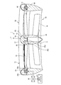
- FIG. 1 is a cross-sectional view of a motor-integrated fan according to the first embodiment.
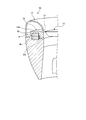
- FIG. 2 is an explanatory diagram of a duct of the motor-integrated fan according to the first embodiment.
- FIG. 3 is a partial cross-sectional view of a modified example of the motor-integrated fan according to the first embodiment.
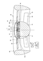
- FIG. 4 is a cross-sectional view of the motor-integrated fan according to the second embodiment.
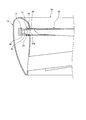
- FIG. 5 is a cross-sectional view of a motor-integrated fan according to the third embodiment.
- FIG. 6 is a partial sectional view of a modified example of the motor-integrated fan according to the third embodiment.
- FIG. 7 is a sectional view of the motor-integrated fan according to the fourth embodiment.
- the motor-integrated fluid machine is an axial fluid machine.
- the motor-integrated fluid machine is a motor-integrated fan 1 (hereinafter referred to as fan 1) that takes in air from a suction port and blows air from a blowout port to generate a propulsive force.
- the motor-integrated fluid machine is described as being applied to the motor-integrated fan 1, but the configuration is not particularly limited to this.
- the motor-integrated fluid machine may be applied, for example, as a motor-integrated propulsion device such as a propeller that generates a propulsive force by taking in a liquid such as water or seawater from a suction port and injecting the liquid from an outlet. ..
- the motor-integrated fan 1 is provided, for example, in a vertical take-off and landing aircraft such as a helicopter or a drone.
- the motor-integrated fan 1 provided in the vertical takeoff and landing aircraft generates a propulsive force for levitating the airframe and a propulsive force for controlling the attitude of the airframe.
- the motor-integrated fan 1 may be applied to an air cushion vehicle such as a hovercraft. Furthermore, when applied as a motor-integrated propulsion device, it may be applied to a ship.
- FIG. 1 is a cross-sectional view of a motor-integrated fan according to the first embodiment.
- FIG. 2 is an explanatory diagram of a duct of the motor-integrated fan according to the first embodiment.
- the motor-integrated fan 1 is called a duct type propeller or a ducted fan.
- the motor-integrated fan 1 is used, for example, in a horizontal state with the axial direction being the vertical direction, takes in air from the upper side in the vertical direction, and blows air to the lower side in the vertical direction.
- the motor-integrated fan 1 may be used in a vertical state in which the axial direction is horizontal.
- the motor-integrated fan 1 is a fan in which one motor is integrally provided, and includes a shaft portion 11, a rotating portion 12, an outer peripheral portion 13, a motor 14, a rolling bearing 15, a current plate 16, and aerodynamic force.
- the device 17 and the control unit 20 are provided.
- the shaft 11 is provided at the center of the rotating shaft I and serves as a support system (fixed side).
- the axis of rotation I has a vertical direction in FIG. 1, and is a direction along the vertical direction. Therefore, the air flow direction is along the axial direction of the rotation axis I.
- the shaft portion 11 includes a shaft-side fitting portion 25, which is a portion provided on the upstream side in the axial direction of the rotation shaft I, and a shaft main body 26, which is a portion provided on the downstream side of the shaft-side fitting portion 25.
- the shaft-side fitting portion 25 is fitted with the hub 31 of the rotating portion 12, which will be described later.
- the shaft-side fitting portion 25 has a cylindrical shape and is provided so as to project in the axial direction from the upstream end surface of the shaft body 26.
- the shaft-side fitting portion 25 has a cylindrical space formed on the center side of the rotating shaft I. A part of the hub 31 of the rotating unit 12 is inserted into this space.
- the outer peripheral side of the shaft side fitting portion 25 is surrounded by a part of the hub 31 of the rotating portion 12.
- the shaft body 26 has a substantially conical shape that tapers from the upstream side to the downstream side in the axial direction.
- the outer peripheral surface of the shaft main body 26 is a surface from the outer side to the inner side in the radial direction from the upstream side to the downstream side in the axial direction.
- the device is, for example, a control device, a camera, or the like.
- an outer end surface of the rectifying plate 16, which will be described later, is connected to the outer peripheral surface of the shaft body 26.
- the rotating unit 12 is a rotating system (rotating side) that rotates around the shaft 11.
- the rotating portion 12 is provided on the inflow side where air flows in with respect to the shaft portion 11 in the axial direction of the rotation shaft I.
- the rotating unit 12 includes a hub 31, a plurality of blades 32, and a rotation support ring 33.
- the hub 31 is provided on the upstream side of the shaft portion 11 in the axial direction, and is rotatably fitted to the shaft-side fitting portion 25.
- the hub 31 has a hub main body 35 that is a portion provided on the upstream side in the axial direction, and a hub side fitting portion 36 that is a portion provided on the downstream side of the hub main body 35.
- the hub body 35 is formed into a hemispherical surface whose upstream end surface has a predetermined radius of curvature.
- the hub-side fitting portion 36 has a shape complementary to the shaft-side fitting portion 25.
- the hub-side fitting portion 36 includes a central shaft 36a provided at the center of the rotating shaft and a cylindrical portion 36b having a cylindrical shape provided on the outer peripheral side of the central shaft 36a.
- the central shaft 36a is inserted into the space at the center of the rotation shaft of the shaft-side fitting portion 25.
- the cylindrical portion 36b is provided so as to project in the axial direction from the end surface on the downstream side of the hub body 35.
- the cylindrical portion 36b is arranged so as to surround the outer periphery of the shaft-side fitting portion 25.
- the rolling bearing 15 is provided between the inner peripheral surface of the shaft-side fitting portion 25 and the outer peripheral surface of the central shaft 36a of the hub 31.
- the surface from the end surface of the hub body 35, through the outer peripheral surface of the cylindrical portion 36b, to the outer peripheral surface of the shaft body 26 is a smooth surface without steps.
- the shaft portion 11 and the hub 31 have a configuration in which unevenness is fitted. That is, the shaft-side fitting portion 25 of the cylindrical shaft portion 11 is made concave, the center shaft 36a of the hub 31 is made convex, and the center shaft 36a is inserted into the shaft-side fitting portion 25 to make the shaft portion 11 and the hub 31 31 and 31 are fitted together.
- the configuration is not limited to this, and the configuration in which the concavities and convexities are fitted may be the reverse configuration.
- the shaft-side fitting portion 25 of the shaft portion 11 is formed in a convex shape
- the hub 31 is provided with a recess portion
- the shaft-side fitting portion 25 is inserted into the recess portion of the hub 31 to connect the shaft portion 11 and the hub 31. It may be configured to be fitted together.
- the rolling bearing 15 is provided between the outer peripheral surface of the shaft side fitting portion 25 and the inner peripheral surface of the recess of the hub 31.
- the plurality of blades 32 are provided so as to extend from the hub 31 toward the outer side in the radial direction, and are arranged side by side at predetermined intervals in the circumferential direction. Each blade 32 has a wing shape.
- the surface formed by rotating the plurality of blades 32 by the end portion on the inflow side orthogonal to the axial direction of the rotation axis I is the rotation surface P.
- the plurality of blades 32 may be made of, for example, a metal material or a composite material, and are not particularly limited.
- the rotation support ring 33 is formed in an annular shape around the rotation axis I.
- the rotation support ring 33 is connected to the outer peripheral side of the plurality of blades 32 in the radial direction of the rotation axis I.
- the rotation support ring 33 includes an inner ring portion 33a that is a portion that forms a part of the inner peripheral surface of the outer peripheral portion 13 described below, and a flange portion 33b that is a portion that is provided so as to project radially outward of the inner ring portion 33a. Is included.
- the inner peripheral surface of the inner ring portion 33 a on the radially inner side is a part of the inner peripheral surface of the outer peripheral portion 13.
- the radially outer ends of the blades 32 are joined to the inner peripheral surface of the inner ring portion 33a by welding or the like, or fixed by using bolts or rivets.
- the flange portion 33b is provided on the upstream side in the axial direction of the inner ring portion 33a.
- the flange portion 33b holds a permanent magnet 45 of the motor 14, which will be described later.
- the flange portion 33b holds the permanent magnet 45 so that the permanent magnet 45 faces the downstream side in the axial direction.
- the hub 12, the plurality of blades 32, and the rotation support ring 33 are integrally joined to the rotating portion 12 and rotate about the hub 31.
- a part or all of the rotating portion 12 may be integrally molded.
- the plurality of blades 32 and the rotation support ring 33 may be integrally molded using a composite material, or the hub 31, the plurality of blades 32, and the rotation support ring 33. May be integrally molded using a composite material.
- the outer peripheral portion 13 is provided on the outer side in the radial direction of the shaft portion 11 and serves as a support system (fixed side).
- the outer peripheral portion 13 is formed in an annular shape and serves as a duct that generates thrust by the rotation of the rotating portion 12.
- the upstream side opening is a suction port 38 and the downstream side opening is a blowout port 39 in the axial direction of the rotating shaft I.
- the duct 13 has an annular internal space formed therein for accommodating a flange portion 33b of the rotation support ring 33 of the rotating portion 12 and a coil 46 of the motor 14, which will be described later.
- the duct 13 holds a coil 46 provided inside the duct 13 at a position facing the permanent magnet 45 held by the rotating unit 12.
- the duct 13 includes an upstream side portion 41 on the inflow side into which air flows in, a downstream side portion 43 on the outflow side from which air flows out, and a portion between the upstream side portion 41 and the downstream side portion 43. And a middle stream side portion 42. That is, the duct 13 is divided into three parts in the axial direction: the upstream part 41, the midstream part 42, and the downstream part 43.
- the outer peripheral surface and the inner peripheral surface of the duct 13 in the upstream portion 41 are curved surfaces having a predetermined radius of curvature r.
- at least the inner peripheral surface of the upstream portion 41 may be a curved surface having a predetermined radius of curvature r.
- the outer peripheral surface and the inner peripheral surface of the duct 13 in the midstream side portion 42 are surfaces having straight portions.
- at least the inner peripheral surface of the midstream side portion 42 may be a surface having a linear portion.
- the surface having the straight line portion is a surface along the axial direction of the rotation axis I.
- a part of the surface having the linear portion is the inner peripheral surface of the inner ring portion 33a of the rotation support ring 33 of the rotating portion 12. That is, the rotating portion 12 is located in the midstream side portion 42 of the duct 13 in the axial direction of the rotating shaft I. Further, in the cross section, the inner peripheral surface of the duct 13 in the downstream side portion 43 is a surface that widens from the inflow side toward the downstream side.
- the diameter of the rotating surface 12 of the rotating portion 12 is set to D, that is, the diameter of the inner peripheral surface of the inner ring portion 33a of the rotating support ring 33 is set to D.
- the diameter D of the rotating portion 12 is longer than the length L1 of the motor-integrated fan 1 in the axial direction of the rotating shaft I.
- the length L1 of the motor-integrated fan 1 in the axial direction of the rotating shaft I is shorter than the diameter D of the rotating portion 12, and is, for example, “0.2D ⁇ L1 ⁇ 0.8D”.
- “0.4D ⁇ L1 ⁇ 0.5D” is satisfied. Therefore, the motor-integrated fan 1 is a flat fan whose length L1 is half the diameter D or less.
- the length of the downstream side portion 43 is longer than the length of the upstream side portion 41 and the length of the midstream side portion 42.
- the predetermined radius of curvature r in the upstream portion 41 is, for example, “0.02D ⁇ L1 ⁇ 0.10D”, specifically, “0.03D ⁇ r ⁇ 0.09D”. ..
- the radius of curvature r may be different on the outer peripheral surface and the inner peripheral surface of the upstream side portion 41 as long as they are within the above numerical range.
- the rotating surface P of the rotating portion 12 is located on the upstream side of the midstream side portion 42. Specifically, if the length L2 at the midstream side portion 42 is, for example, 0.1D, the length L3 from the upstream boundary of the midstream side portion 42 to the rotation surface P is, for example, 0.01D. Is becoming
- the spread of the inner peripheral surface of the downstream side portion 43 will be described.
- the angle formed by the inner circumferential surface of the downstream side portion 43 and the direction along the inner circumferential surface of the midstream side portion 42 (the axial direction of the rotation axis I) is ,
- the diffuser angle ⁇ is “0° ⁇ 30°”.
- the duct 13 has the above-described shape, when the rotating unit 12 rotates, air is sucked from the suction port 38 and the sucked air is blown out from the blowout port 39 to generate thrust.
- the motor 14 is an outer peripheral drive motor that rotates the rotating part 12 by applying power from the duct 13 side to the rotating part 12.
- the motor 14 has a rotor-side magnet provided on the rotating unit 12 side and a stator-side magnet provided on the duct 13 side.
- the rotor-side magnet is the permanent magnet 45
- the stator-side magnet is the coil (electromagnet) 46.
- the coil 46 is provided in the support system to simplify the configuration related to the wiring around the coil 46, but the configuration is not particularly limited to this.
- the rotor side magnet may be a coil
- the stator side magnet may be a permanent magnet 45.
- the permanent magnet 45 is provided so as to be held by the flange portion 33b of the rotation support ring 33, and is arranged in an annular shape in the circumferential direction. Further, the permanent magnet 45 is configured such that the positive electrode and the negative electrode are alternately arranged at predetermined intervals in the circumferential direction.
- the permanent magnets 45 may have a Halbach array.
- the permanent magnet 45 is provided at a position facing the coil 46 in the axial direction of the rotation axis I.
- the permanent magnet 45 has a length in the radial direction of the rotary shaft I that is longer than the length in the axial direction of the rotary shaft I.
- the coil 46 is provided while being held inside the duct 13, a plurality of coils 46 are provided facing each pole of the permanent magnet 45, and are arranged side by side in the circumferential direction.
- the coil 46 is provided at a position facing the permanent magnet 45 held by the rotating portion 12 in the axial direction of the rotating shaft I. That is, the permanent magnet 45 and the coil 46 are arranged axially so as to face each other in the axial direction of the rotation axis I.
- the rolling bearing 15 is provided between the inner peripheral surface of the shaft-side fitting portion 25 of the shaft portion 11 and the outer peripheral surface of the central shaft 36a of the hub 31 of the rotating portion 12.
- the rolling bearing 15 connects the shaft portion 11 and the rotation portion 12 while allowing the rotation portion 12 to rotate with respect to the shaft portion 11.
- the rolling bearing 15 is, for example, a ball bearing or the like.
- the current plate 16 is provided by connecting the shaft portion 11 and the duct 13.
- the current plate 16 is provided on the downstream side of the rotating unit 12 in the axial direction of the rotating shaft I. That is, the current plate 16 is provided at the position of the downstream side portion 43 of the duct 13 in the axial direction.
- the straightening vanes 16 are arranged side by side in the circumferential direction of the rotation axis I. Further, the current plate 16 has a streamlined shape such as a blade shape, and rectifies the air flowing from the rotating portion 12 to generate thrust.
- the shape of the current plate 16 is not limited to the blade shape, and may be a flat plate shape.
- the aerodynamic device 17 is provided on the inner peripheral surface of the duct 13 on the downstream side of the rotating unit 12.
- the aerodynamic device 17 suppresses separation of air flowing along the inner peripheral surface of the duct 13.
- the aerodynamic device 17 is a plasma actuator, a synthetic jet, or the like.
- the aerodynamic device 17 the one that applies a flow toward the downstream side to the air is applied so that the flow of the air along the inner peripheral surface of the duct 13 becomes the flow toward the downstream side, Specifically, a plasma actuator is applied.
- the aerodynamic device 17 is provided around the boundary between the midstream side portion 42 and the downstream side portion 43 of the duct 13 in the axial direction of the rotation axis I. Specifically, the aerodynamic device 17 is provided at least on the boundary side of the midstream side portion 42. The aerodynamic device 17 may be provided on the inner peripheral surface of the downstream side portion 43, and is appropriately provided on a portion where air separation may occur.
- the control unit 20 is connected to each unit of the motor-integrated fan 1 and controls each unit to control the motor-integrated fan 1.
- the control unit 20 is connected to the coil 46.
- the control unit 20 controls the rotation of the rotating unit 12 by controlling the magnetic field of the coil 46.
- the control unit 20 is also connected to the aerodynamic device 17.
- the control unit 20 controls the operation of the aerodynamic device 17. Further, a rotation speed detection sensor (not shown) is connected to the control unit 20, and acquires the rotation speed of the rotation unit 12.
- the control unit 20 controls the operation of the aerodynamic device 17 based on the rotation speed of the rotation unit 12 detected by the rotation speed detection sensor. Specifically, the control unit 20 operates the aerodynamic device 17 until the rotation unit 12 reaches a predetermined rotation speed. That is, the control unit 20 operates the aerodynamic device 17 in the low speed rotation range until the rotation unit 12 reaches a predetermined rotation speed. On the other hand, the control unit 20 stops the operation of the aerodynamic device 17 in the rotation range where the rotation unit 12 has a predetermined rotation speed or more.
- the predetermined rotation speed is, for example, a commonly used rotation speed or a rated rotation speed in a rated operating state.
- the rotating portion 12 is rotated by applying power from the duct 13 side to the rotating portion 12 by the magnetic field by the motor 14.
- the motor-integrated fan 1 sucks air from the suction port 38 and blows air toward the air outlet 39.
- the air blown out from the rotating portion 12 flows along the inner peripheral surface of the duct 13 to generate thrust.
- the aerodynamic device 17 suppresses the separation of air from the inner peripheral surface of the duct 13, and the flow of the air is rectified by the rectifying plate 16, so that the rectifying plate 16 also generates thrust.
- the rotating portion 12 can rotate while being rotatably supported by at least the shaft portion 11. For this reason, it is possible to prevent the rotating portion 12 from moving in the axial direction of the rotating shaft I due to the influence of vibration or the like during rotation, so that the rotating portion 12 can be rotated appropriately. Further, since the rotating portion 12 can have a simple structure including the plurality of blades 32 and the rotation supporting ring 33, the rotating portion 12 can be configured compactly.
- the rotating unit 12 can be rotated by the motor 14 that is driven on the outer periphery. Moreover, since the motor 14 can be provided on the outer peripheral side of the rotation support ring 33, the configuration of the shaft portion 11 can be simplified.
- the permanent magnet 45 and the coil 46 can be arranged over the surface orthogonal to the axial direction of the rotation axis I. Therefore, since the installation areas of the permanent magnet 45 and the coil 46 can be widened, the rotation output of the motor 14 can be increased.
- the rotating portion 12 can be arranged on the upstream side with respect to the shaft portion 11, the length of the flow path of the air flowing into the rotating portion 12 is shortened and The length of the flow path of the outflowing air can be increased. Therefore, when the thrust is generated by air, it is easy to suck the air because the flow path of the air flowing into the rotating portion 12 is short, and the air is appropriately blown out because the flow path of the air flowing out of the rotating portion 12 is long. Therefore, the thrust can be configured to be high.
- the thrust can be appropriately generated by the duct 13.
- the aerodynamic device 17 can suppress the air separation on the inner peripheral surface of the duct 13, it is possible to suppress the decrease in the thrust.
- the inner peripheral surface of the duct 13 is activated by operating the aerodynamic device 17. Since the separation of the air from the can be suppressed, the air can be made to flow along the inner peripheral surface of the duct 13.
- the rotation surface P can be positioned on the upstream side of the midstream side portion 42 and the rotating portion 12 can be rotated at the midstream side portion 42. Therefore, the air sucked in the upstream portion 41 can be blown out in the downstream portion 43, so that the thrust can be appropriately generated.
- the rotating portion 12 and the shaft portion 11 are rotatably connected to each other, thereby restricting the movement of the rotating portion 12 in the axial direction while rotating the rotating portion 12.
- the part 12 can be rotated smoothly.
- the air from the rotating portion 12 can be rectified and blown out from the air outlet 39.
- the compact motor-integrated fan 1 by mounting the compact motor-integrated fan 1 on the vertical take-off and landing aircraft, it is possible to reduce the weight, and the motor-integrated fan 1 can generate an appropriate thrust.
- FIG. 3 is a partial cross-sectional view of a modified example of the motor-integrated fan according to the first embodiment.
- the permanent magnet 45 and the coil 46 are arranged in a radial arrangement in which they are arranged to face each other in the radial direction of the rotation axis I.
- the rotary support ring 33 that holds the permanent magnet 45 has a structure in which the flange portion 33b is omitted, and holds the permanent magnet 45 on the outer peripheral side of the inner ring portion 33a.
- the permanent magnet 45 is held and provided on the outer peripheral side of the inner ring portion 33a of the rotation support ring 33, and is arranged in an annular shape in the circumferential direction.
- the permanent magnet 45 is provided at a position facing the coil 46 in the radial direction of the rotation axis I.
- the coils 46 are provided while being held inside the duct 13, a plurality of coils 46 are provided so as to face each pole of the permanent magnet 45, and the coils 46 are provided side by side in the circumferential direction.
- the coil 46 is provided at a position facing the permanent magnet 45 held by the rotating portion 12 in the radial direction of the rotating shaft I. In this way, the permanent magnet 45 and the coil 46 may be arranged radially opposite to each other in the radial direction of the rotation axis I.
- the permanent magnet 45 of the rotation support ring 33 is provided inside the rotating shaft I in the radial direction, and the coil 46 provided inside the duct 13 is provided outside the rotating shaft I in the radial direction.
- the permanent magnet 45 of the rotation support ring 33 may be provided on the outer side in the radial direction of the rotary shaft I, and the coil 46 provided inside the duct 13 may be provided on the inner side in the radial direction of the rotary shaft I.
- FIG. 4 is a cross-sectional view of the motor-integrated fan according to the second embodiment.
- the motor-integrated fan 50 according to the second embodiment further includes a rolling bearing 51 between the rotating portion 12 and the duct 13 in addition to the configuration of the motor-integrated fan 1 according to the first embodiment.
- the rolling bearings 51 are provided on both sides of the inner ring portion 33a of the rotation support ring 33 in the axial direction of the rotation shaft I. Therefore, in the motor-integrated fan 50, the rotating portion 12 is rotatably supported by the shaft portion 11 and the duct 13.
- the rotating portion 12 and the shaft portion 11 and the rotating portion 12 and the duct 13 are rotatably connected. By doing so, the rotating portion 12 can be smoothly rotated while restricting the movement of the rotating portion 12 in the axial direction.
- the rolling bearing 51 when the rolling bearing 51 is provided between the rotating portion 12 and the duct 13, the rolling bearing 15 provided between the rotating portion 12 and the shaft portion 11 may be omitted. Good.
- FIG. 5 is a cross-sectional view of a motor-integrated fan according to the third embodiment.
- the motor-integrated fan 1 of the first embodiment is a motor in which the motor 14 is driven on the outer circumference
- the motor-integrated fan 60 of the third embodiment is a motor in which the motor 64 is driven in the inner circumference.
- the motor-integrated fan 60 includes a shaft portion 61, a rotating portion 62, a duct 63, a motor 64, a rolling bearing 65, a current plate 66, an aerodynamic device 67, and a control portion 70. ing. Since the rolling bearing 65, the current plate 66, the aerodynamic device 67, and the control unit 70 are almost the same as those in the first embodiment, the description thereof will be omitted.
- the shaft portion 61 is provided at the center of the rotating shaft I and serves as a support system (fixed side).
- the shaft portion 61 includes a shaft-side fitting portion 75, which is a portion provided on the upstream side in the axial direction of the rotation shaft I, and a shaft main body 76, which is a portion provided on the downstream side of the shaft-side fitting portion 75.
- the shaft side fitting portion 75 is fitted with a rotation support ring 83 of the rotating portion 62 described later.
- the shaft-side fitting portion 75 has a cylindrical shape, and is provided on the upstream end surface of the shaft body 76 so as to project from the center of the rotation shaft I to the upstream side in the axial direction.
- the outer peripheral side of the shaft-side fitting portion 75 is surrounded by the rotation support ring 83 of the rotating portion 62.
- the shaft body 76 has a hemispherical shape that is convex from the upstream side to the downstream side in the axial direction. For this reason, the outer peripheral surface of the shaft main body 76 is a surface from the outer side to the inner side in the radial direction from the upstream side to the downstream side in the axial direction. Further, the shaft main body 76 holds the coil 46 at a position on the outer peripheral side of the shaft side fitting portion 75 on the end face on the upstream side in the axial direction. Note that, as in the first embodiment, an internal space in which a device can be installed may be formed inside the shaft body 76.
- the rotating part 62 is a rotating system (rotating side) that rotates around the shaft part 61.
- the rotating portion 62 is provided on the inflow side where air flows in with respect to the shaft portion 61 in the axial direction of the rotating shaft I.
- the rotating portion 62 has a hub 81, a plurality of blades 82, and a rotation support ring 83.
- the hub 81 is provided on the upstream side of the shaft 61 in the axial direction.
- the hub 81 is formed into a spherical surface whose upstream end surface has a predetermined radius of curvature.
- the rotation support ring 83 is provided on the downstream side of the hub 81 in the axial direction and is integrated with the hub 81.
- the rotation support ring 83 is rotatably fitted in the shaft-side fitting portion 75.
- the rotation support ring 83 is formed in an annular shape around the rotation axis I.
- the rotation support ring 83 includes an outer ring portion 83a provided on the outer side in the radial direction, a flange portion 83b that is a portion provided to project radially inward of the outer ring portion 83a, and a portion provided on the inner side in the radial direction of the flange portion 83b.
- the outer ring portion 83a has a cylindrical shape, and has a smooth outer peripheral surface having no step with respect to the outer peripheral surface of the shaft portion 61.
- the radially inner end of each blade 82 is joined to the outer peripheral surface of the outer ring portion 83a by welding or the like, or is fixed by using a bolt or a rivet.
- the flange portion 83b is provided on the upstream side in the axial direction of the outer ring portion 83a.
- the flange portion 83b holds the permanent magnet 45 of the motor 64, which will be described later.
- the flange portion 83b holds the permanent magnet 45 so that the permanent magnet 45 faces the downstream side in the axial direction.
- the inner ring portion 83c has a cylindrical shape and is provided so as to surround the shaft-side fitting portion 75.
- the inner peripheral surface of the inner ring portion 83c faces the outer peripheral surface of the shaft-side fitting portion 75.
- the rolling bearing 65 is provided between the outer peripheral surface of the shaft side fitting portion 75 of the shaft portion 11 and the inner peripheral surface of the inner ring portion 83 c of the rotation support ring 83.
- the shaft portion 61 and the rotation support ring 83 integrated with the hub 81 have a configuration in which unevenness is fitted. That is, the inner ring portion 83c of the cylindrical rotation support ring 83 is concave, the shaft-side fitting portion 75 of the shaft portion 61 is convex, and the shaft-side fitting portion 75 is inserted into the inner ring portion 83c.
- the part 61 and the rotation support ring 83 are fitted together.
- the configuration is not limited to this, and the configuration in which the concavities and convexities are fitted may be the reverse configuration.
- the shaft side fitting portion 75 of the shaft portion 61 is formed in a concave shape
- the rotation supporting ring 83 is provided with a convex portion
- the projection portion of the rotation supporting ring 83 is inserted into the shaft side fitting portion 75 of the shaft portion 61.
- the shaft portion 61 and the hub 81 may be fitted together.
- the rolling bearing 65 is provided between the inner peripheral surface of the shaft side fitting portion 75 and the outer peripheral surface of the convex portion of the rotation support ring 83.
- the configuration of such fitting of the concavities and convexities is almost the same as that described in the first embodiment.
- the plurality of blades 82 are connected to the outer peripheral surface of the rotation support ring 83.
- the plurality of blades 82 are provided so as to extend outward from the rotation support ring 83 in the radial direction, and are arranged side by side at predetermined intervals in the circumferential direction.
- Each blade 32 has a wing shape. Further, each blade 32 has its radially inner end connected to the outer peripheral surface of the rotation support ring 83, while its radially outer end is a free end.
- the plurality of blades 82 may be made of, for example, a metal material or a composite material, and are not particularly limited.
- the hub 81, the plurality of blades 82, and the rotation support ring 83 are integrally joined to the rotating portion 62, and rotate about the hub 81.
- a part or all of the rotating portion 62 may be integrally molded.
- the plurality of blades 82 and the rotation support ring 83 may be integrally molded using a composite material, or the hub 81, the plurality of blades 82, and the rotation support ring 83. May be integrally molded using a composite material.
- the duct 63 is provided on the outer side in the radial direction of the shaft portion 61 and serves as a support system (fixed side).
- the duct 63 is formed in an annular shape and serves as a duct that generates thrust by the rotation of the rotating portion 62.
- the opening on the upstream side is the suction port 38 and the opening on the downstream side is the air outlet 39.
- the shape of the duct 63 is similar to that of the first embodiment.
- the motor 64 is an inner peripheral drive motor that rotates the rotating portion 62 by applying power from the shaft portion 61 side to the rotating portion 62.
- the motor 64 has a rotor-side magnet provided on the rotating portion 62 side and a stator-side magnet provided on the shaft portion 61 side.
- the rotor-side magnet is the permanent magnet 45
- the stator-side magnet is the coil (electromagnet) 46.
- the coil 46 is provided in the support system to simplify the configuration of the wiring around the coil 46, but the configuration is not limited to this.
- the rotor side magnet may be a coil
- the stator side magnet may be a permanent magnet 45.
- the permanent magnet 45 is provided so as to be held by the flange portion 83b of the rotation support ring 83, and is arranged in an annular shape in the circumferential direction.
- the rest of the configuration of the permanent magnet 45 is the same as that of the first embodiment, and the description thereof is omitted.
- the coil 46 is provided so as to be held on the upstream end surface of the shaft body 76 of the shaft portion 61, and a plurality of coils 46 are provided so as to face each pole of the permanent magnet 45 and are arranged side by side in the circumferential direction. Since the other configurations of the coil 46 are the same as those in the first embodiment, the description thereof will be omitted.
- the rotating portion 62 is rotated by applying power from the magnetic field to the rotating portion 62 from the shaft portion 61 side by the motor 64.
- the motor-integrated fan 60 sucks air from the suction port 38 and blows air toward the air outlet 39.
- the air blown out from the rotating portion 62 flows along the inner peripheral surface of the duct 63 to generate thrust.
- the rotating portion 62 can rotate while being rotatably supported by at least the shaft portion 61. For this reason, it is possible to prevent the rotating portion 62 from moving in the axial direction of the rotating shaft I due to the influence of vibration or the like during rotation, so that the rotating portion 62 can be appropriately rotated. Further, since the rotating portion 62 can have a simple structure including the plurality of blades 82 and the rotation support ring 83, the rotating portion 62 can be made compact.
- the rotating portion 62 can be rotated by the motor 64 that is driven inward. Further, since the motor 64 can be provided on the inner peripheral side of the rotation support ring 83, the structure of the duct 63 can be simplified.
- FIG. 6 is a partial sectional view of a modified example of the motor-integrated fan according to the third embodiment.
- the permanent magnet 45 and the coil 46 are arranged in a radial arrangement in which they are arranged to face each other in the radial direction of the rotation axis I.
- the permanent magnet 45 is held and provided on the outer peripheral side of the inner ring portion 83c of the rotation support ring 83, and is arranged in an annular shape in the circumferential direction.
- the permanent magnet 45 is provided at a position facing the coil 46 in the radial direction of the rotation axis I.
- the coils 46 are held and provided inside the shaft portion 61, and a plurality of coils 46 are provided so as to face each pole of the permanent magnet 45 and are arranged side by side in the circumferential direction.
- the coil 46 is provided at a position facing the permanent magnet 45 held by the rotating portion 62 in the radial direction of the rotating shaft I. In this way, the permanent magnet 45 and the coil 46 may be arranged radially opposite to each other in the radial direction of the rotation axis I.
- FIG. 7 is a sectional view of the motor-integrated fan according to the fourth embodiment.
- the motor-integrated fan 90 of the fourth embodiment uses a magnetic bearing 91 instead of the rolling bearing 51 provided in the motor-integrated fan 50 of the second embodiment.
- the magnetic bearing 91 includes a pair of rotation-side magnets 95 provided on both sides in the axial direction of the inner ring portion 33 a of the rotation support ring 33, and a pair of fixed sides of the duct 13 facing the pair of rotation-side magnets 95. And a magnet 96.
- the rotating magnet 95 is a permanent magnet
- the stationary magnet 96 is a coil.
- the rotation-side magnet 95 and the fixed-side magnet 96 are provided so as to face each other in the axial direction of the rotation axis I.
- the rotating magnet 95 may be a coil
- the stationary magnet 96 may be a permanent magnet.
- the magnetic bearing 91 rotatably supports the rotation support ring 33 in a non-contact state with the duct 13 by controlling the magnetic field so that the rotation-side magnet 95 and the fixed-side magnet 96 repel each other. ing.
- the permanent magnet 45 of the motor 14 is provided radially outside of the inner ring portion 33a of the rotation support ring 33, and the coil 46 is a permanent magnet in the radial direction of the rotating shaft.
- the duct 13 is provided so as to face 45.
- the rotating part 12 can be smoothly rotated in a state where the rotating part 12 and the duct 13 are not connected. Therefore, it is possible to prevent the load applied to the rotating unit 12 from being transmitted to the duct 13.
- the rolling bearing 51 provided in the motor integrated fan 50 of the second embodiment is the magnetic bearing 91, but the rolling bearing 15 provided in the motor integrated fan 1 of the first embodiment is a magnetic bearing. It may be 91.
Landscapes
- Engineering & Computer Science (AREA)
- Aviation & Aerospace Engineering (AREA)
- Chemical & Material Sciences (AREA)
- Combustion & Propulsion (AREA)
- Power Engineering (AREA)
- Mechanical Engineering (AREA)
- Structures Of Non-Positive Displacement Pumps (AREA)
- Permanent Magnet Type Synchronous Machine (AREA)
- Connection Of Motors, Electrical Generators, Mechanical Devices, And The Like (AREA)
Abstract
Description
実施形態1に係るモータ一体型流体機械は、軸流の流体機械となっている。モータ一体型流体機械は、吸込口から空気を取り込み、吹出口から空気を吹き出すことで、推進力を発生させるモータ一体型ファン1(以下、ファン1という)である。なお、実施形態1では、モータ一体型流体機械として、モータ一体型ファン1に適用して説明するが、この構成に特に限定されない。モータ一体型流体機械は、例えば、吸込口から水または海水等の液体を取り込み、吹出口から液体を噴射することで、推進力を発生させるプロペラ等のモータ一体型推進器として適用してもよい。
次に、図4を参照して、実施形態2に係るモータ一体型ファン50について説明する。なお、実施形態2では、重複した記載を避けるべく、実施形態1と異なる部分について説明し、実施形態1と同様の構成である部分については、同じ符号を付して説明する。図4は、実施形態2に係るモータ一体型ファンに関する断面図である。
次に、図5を参照して、実施形態3に係るモータ一体型ファン60について説明する。なお、実施形態3でも、重複した記載を避けるべく、実施形態1及び2と異なる部分について説明し、実施形態1及び2と同様の構成である部分については、同じ符号を付して説明する。図5は、実施形態3に係るモータ一体型ファンに関する断面図である。
次に、図7を参照して、実施形態4に係るモータ一体型ファン90について説明する。なお、実施形態4でも、重複した記載を避けるべく、実施形態1から3と異なる部分について説明し、実施形態1から3と同様の構成である部分については、同じ符号を付して説明する。図7は、実施形態4に係るモータ一体型ファンに関する断面図である。
11 軸部
12 回転部
13 ダクト
14 モータ
15 転がり軸受
16 整流板
17 空力デバイス
20 制御部
31 ハブ
32 ブレード
33 回転支持リング
38 吸込口
39 吹出口
41 上流側部位
42 中流側部位
43 下流側部位
45 永久磁石
46 コイル
50 モータ一体型ファン(実施形態2)
51 転がり軸受
60 モータ一体型ファン(実施形態3)
61 軸部
62 回転部
63 ダクト
64 モータ
65 転がり軸受
66 整流板
67 空力デバイス
70 制御部
81 ハブ
82 ブレード
83 回転支持リング
90 モータ一体型ファン(実施形態4)
91 磁気軸受
95 回転側磁石
96 固定側磁石
Claims (14)
- 1以上のモータが一体に設けられるモータ一体型流体機械において、
回転軸の中心に設けられる支持系となる軸部と、
前記軸部を中心に回転する回転系となる回転部と、
前記軸部の外周に設けられる支持系となる外周部と、
前記回転部を回転させるモータと、を備え、
前記回転部は、少なくとも前記軸部に回転自在に支持されて回転し、
前記回転軸の周方向において並べて設けられる複数のブレードと、
前記回転軸の径方向において、複数の前記ブレードの一方側に接続され、複数の前記ブレードを支持する回転支持部材と、を有するモータ一体型流体機械。 - 前記モータは、前記外周部から動力を与えて前記回転部を回転させる外周駆動のモータとなっており、
前記回転部は、
前記回転支持部材が、前記回転軸を中心とする円環形状に形成されると共に、前記回転軸の径方向において、複数の前記ブレードの外周側に接続される回転支持リングとなっており、
前記モータは、
前記回転支持リングの前記径方向の外周側に設けられる回転子側磁石と、
前記外周部の内周側に設けられ、前記回転子側磁石に対向して設けられる固定子側磁石と、を有する請求項1に記載のモータ一体型流体機械。 - 前記モータは、前記軸部から動力を与えて前記回転部を回転させる内周駆動のモータとなっており、
前記回転部は、
前記回転支持部材が、前記回転軸を中心とする円環形状に形成されると共に、前記回転軸の径方向において、複数の前記ブレードの内周側に接続される回転支持リングとなっており、
前記モータは、
前記回転支持リングの前記径方向の内周側に設けられる回転子側磁石と、
前記軸部の外周側に設けられ、前記回転子側磁石に対向して設けられる固定子側磁石と、を有する請求項1に記載のモータ一体型流体機械。 - 前記回転子側磁石と前記固定子側磁石とは、前記回転軸の軸方向に対向して設けられる請求項2または3に記載のモータ一体型流体機械。
- 前記回転子側磁石と前記固定子側磁石とは、前記回転軸の径方向に対向して設けられる請求項2または3に記載のモータ一体型流体機械。
- 前記回転部は、前記回転軸の軸方向において、前記軸部に対して、流体が流入する流入側に設けられる請求項1から5のいずれか1項に記載のモータ一体型流体機械。
- 前記外周部は、円環形状に形成され、前記回転部の回転により推力を生じさせるダクトであり、
前記ダクトは、流体が流入する流入側の上流側部位と、前記流体が流出する流出側の下流側部位と、前記上流側部位と前記下流側部位との間の中流側部位と、を有し、
前記上流側部位の少なくとも内周面は、前記回転軸の周方向に直交する面で切った断面において、所定の曲率半径を有する面となっており、
前記中流側部位の内周面は、前記断面において、直線部を有する面となっており、
前記下流側部位の内周面は、前記断面において、流入側から下流側に向かって広がる面となっている請求項1から6のいずれか1項に記載のモータ一体型流体機械。 - 前記回転部の流出側における前記ダクトの内周面に設けられ、前記内周面に沿って流れる流体のはく離を抑制する空力デバイスを、さらに備え、
前記空力デバイスは、前記中流側部位と前記下流側部位との境界において、少なくとも前記中流側部位の前記境界側に設けられる請求項7に記載のモータ一体型流体機械。 - 前記空力デバイスを制御する制御部を、さらに備え、
前記制御部は、前記回転部が所定の回転数に達するまで、前記空力デバイスを作動させる請求項8に記載のモータ一体型流体機械。 - 前記回転部の前記回転軸の軸方向に直交する流入側の面を回転面とすると、
前記回転面は、前記軸方向において、前記中流側部位に位置する請求項7から9のいずれか1項に記載のモータ一体型流体機械。 - 前記回転部と前記外周部との間、及び前記回転部と前記軸部との間の少なくとも一方に設けられる転がり軸受を、さらに備える請求項1から10のいずれか1項に記載のモータ一体型流体機械。
- 前記回転部と前記外周部との間、及び前記回転部と前記軸部との間の少なくとも一方に設けられる磁気軸受を、さらに備える請求項1から10のいずれか1項に記載のモータ一体型流体機械。
- 前記回転部の流出側に設けられ、前記軸部と前記外周部とを連結すると共に、前記回転部からの流体の流れを整える整流板を、さらに備える請求項1から12のいずれか1項に記載のモータ一体型流体機械。
- 請求項1から13のいずれか1項に記載のモータ一体型流体機械と、
前記モータ一体型流体機械から発生する推力によって移動する機体と、を備える垂直離着陸機。
Priority Applications (2)
| Application Number | Priority Date | Filing Date | Title |
|---|---|---|---|
| US17/299,098 US12246842B2 (en) | 2018-12-13 | 2019-10-30 | Motor-integrated fluid machine and vertical take-off and landing aircraft |
| EP19896687.1A EP3875369B1 (en) | 2018-12-13 | 2019-10-30 | Motor-integrated fluid machine and vertical take-off and landing aircraft |
Applications Claiming Priority (2)
| Application Number | Priority Date | Filing Date | Title |
|---|---|---|---|
| JP2018233716A JP7269722B2 (ja) | 2018-12-13 | 2018-12-13 | モータ一体型流体機械及び垂直離着陸機 |
| JP2018-233716 | 2018-12-13 |
Publications (1)
| Publication Number | Publication Date |
|---|---|
| WO2020121671A1 true WO2020121671A1 (ja) | 2020-06-18 |
Family
ID=71075778
Family Applications (1)
| Application Number | Title | Priority Date | Filing Date |
|---|---|---|---|
| PCT/JP2019/042502 Ceased WO2020121671A1 (ja) | 2018-12-13 | 2019-10-30 | モータ一体型流体機械及び垂直離着陸機 |
Country Status (4)
| Country | Link |
|---|---|
| US (1) | US12246842B2 (ja) |
| EP (1) | EP3875369B1 (ja) |
| JP (1) | JP7269722B2 (ja) |
| WO (1) | WO2020121671A1 (ja) |
Families Citing this family (7)
| Publication number | Priority date | Publication date | Assignee | Title |
|---|---|---|---|---|
| WO2018175349A1 (en) * | 2017-03-19 | 2018-09-27 | Zunum Aero, Inc. | Hybrid-electric aircraft, and methods, apparatus and systems for facilitating same |
| CN112912691A (zh) * | 2018-08-26 | 2021-06-04 | 航空电机工程有限公司 | 电磁陀螺稳定推进系统方法及设备 |
| WO2020150747A1 (en) | 2019-01-20 | 2020-07-23 | Airborne Motors, Llc | Medical stabilizer harness method and apparatus |
| JP7413013B2 (ja) * | 2019-12-27 | 2024-01-15 | 三菱重工業株式会社 | モータ一体型流体機械、垂直離着陸機及びモータ一体型流体機械の設計方法 |
| US12546287B2 (en) | 2020-02-28 | 2026-02-10 | Airborne Motorworks Inc. | Sound vibration and friction limiting turbine generator gyroscope method and apparatus |
| JP7629597B2 (ja) * | 2021-02-08 | 2025-02-14 | 株式会社ドローン技術研究所 | シャフト無し推進装置 |
| JP7558122B2 (ja) * | 2021-07-15 | 2024-09-30 | 三菱重工業株式会社 | 電動ファンおよび電動垂直離着陸機 |
Citations (7)
| Publication number | Priority date | Publication date | Assignee | Title |
|---|---|---|---|---|
| US3708251A (en) * | 1968-07-01 | 1973-01-02 | North American Rockwell | Gearless drive method and means |
| US4459087A (en) * | 1982-06-02 | 1984-07-10 | Aciers Et Outillage Peugeot | Fan unit for an internal combustion engine of automobile vehicle |
| US4953811A (en) * | 1988-10-19 | 1990-09-04 | The United States Of America As Represented By The Secretary Of The Army | Self-driving helicopter tail rotor |
| JP2001097288A (ja) * | 1999-09-30 | 2001-04-10 | Mitsubishi Heavy Ind Ltd | ヘリコプタダクテッドファン |
| US20110272520A1 (en) * | 2009-10-30 | 2011-11-10 | Beijing University Of Technology | Electrical driven flying saucer based on magnetic suspension |
| DE102011054849B3 (de) * | 2011-10-27 | 2013-01-31 | Deutsches Zentrum für Luft- und Raumfahrt e.V. | Heckrotoranordnung |
| JP2013139247A (ja) | 2011-12-28 | 2013-07-18 | Eurocopter Deutschland Gmbh | ヘリコプタの電動テールロータ |
Family Cites Families (15)
| Publication number | Priority date | Publication date | Assignee | Title |
|---|---|---|---|---|
| US5220231A (en) * | 1990-08-23 | 1993-06-15 | Westinghouse Electric Corp. | Integral motor propulsor unit for water vehicles |
| US5185545A (en) * | 1990-08-23 | 1993-02-09 | Westinghouse Electric Corp. | Dual propeller shock resistant submersible propulsor unit |
| FR2712562B1 (fr) * | 1993-11-17 | 1996-01-12 | Cosmos | Ensemble propulseur pour aéronef léger et lent. |
| FR2719551B1 (fr) * | 1994-05-04 | 1996-07-12 | Eurocopter France | Dispositif anti-couple à rotor et stator redresseur carénés, et à aubes redresseuses inclinées. |
| US6390418B1 (en) * | 1999-02-25 | 2002-05-21 | United Technologies Corporation | Tangentially directed acoustic jet controlling boundary layer |
| US6464459B2 (en) * | 1999-05-21 | 2002-10-15 | Avionic Instruments, Inc. | Lifting platform with energy recovery |
| US7032859B2 (en) * | 2004-07-23 | 2006-04-25 | The United States Of America As Represented By The Secretary Of The Navy | Counter rotating ducted fan having a permanent magnet drive |
| US8123460B2 (en) * | 2008-07-23 | 2012-02-28 | Honeywell International Inc. | UAV pod cooling using integrated duct wall heat transfer |
| US8668449B2 (en) * | 2009-06-02 | 2014-03-11 | Siemens Energy, Inc. | Turbine exhaust diffuser with region of reduced flow area and outer boundary gas flow |
| NL2011128C2 (nl) * | 2013-07-09 | 2015-01-12 | Eco Logical Entpr B V | Rotatie-inrichting, bijvoorbeeld een luchtverplaatser, zoals een ventilator, een propeller of een hefschroef, een waterturbine of een windturbine. |
| US20170104385A1 (en) * | 2015-10-08 | 2017-04-13 | Adam C. Salamon | Reduced Complexity Ring Motor Design for Propeller Driven Vehicles |
| US11485486B2 (en) * | 2016-05-18 | 2022-11-01 | The University Of Toledo | Active flow control for ducted fans and fan-in-wing configurations |
| US10473107B1 (en) * | 2017-11-29 | 2019-11-12 | Stephen Thomas Newton | Variable performance axial flow ducted fan with high efficiency and reduced current drawn |
| US11352132B2 (en) * | 2018-07-23 | 2022-06-07 | General Electric Company | Lift fan with diffuser duct |
| JP7281911B2 (ja) * | 2019-01-30 | 2023-05-26 | 三菱重工業株式会社 | モータ一体型流体機械及び垂直離着陸機 |
-
2018
- 2018-12-13 JP JP2018233716A patent/JP7269722B2/ja active Active
-
2019
- 2019-10-30 WO PCT/JP2019/042502 patent/WO2020121671A1/ja not_active Ceased
- 2019-10-30 EP EP19896687.1A patent/EP3875369B1/en active Active
- 2019-10-30 US US17/299,098 patent/US12246842B2/en active Active
Patent Citations (7)
| Publication number | Priority date | Publication date | Assignee | Title |
|---|---|---|---|---|
| US3708251A (en) * | 1968-07-01 | 1973-01-02 | North American Rockwell | Gearless drive method and means |
| US4459087A (en) * | 1982-06-02 | 1984-07-10 | Aciers Et Outillage Peugeot | Fan unit for an internal combustion engine of automobile vehicle |
| US4953811A (en) * | 1988-10-19 | 1990-09-04 | The United States Of America As Represented By The Secretary Of The Army | Self-driving helicopter tail rotor |
| JP2001097288A (ja) * | 1999-09-30 | 2001-04-10 | Mitsubishi Heavy Ind Ltd | ヘリコプタダクテッドファン |
| US20110272520A1 (en) * | 2009-10-30 | 2011-11-10 | Beijing University Of Technology | Electrical driven flying saucer based on magnetic suspension |
| DE102011054849B3 (de) * | 2011-10-27 | 2013-01-31 | Deutsches Zentrum für Luft- und Raumfahrt e.V. | Heckrotoranordnung |
| JP2013139247A (ja) | 2011-12-28 | 2013-07-18 | Eurocopter Deutschland Gmbh | ヘリコプタの電動テールロータ |
Non-Patent Citations (1)
| Title |
|---|
| See also references of EP3875369A4 |
Also Published As
| Publication number | Publication date |
|---|---|
| EP3875369B1 (en) | 2025-12-03 |
| JP2020093705A (ja) | 2020-06-18 |
| EP3875369A1 (en) | 2021-09-08 |
| EP3875369A4 (en) | 2021-12-29 |
| JP7269722B2 (ja) | 2023-05-09 |
| US20220063820A1 (en) | 2022-03-03 |
| US12246842B2 (en) | 2025-03-11 |
Similar Documents
| Publication | Publication Date | Title |
|---|---|---|
| JP7269722B2 (ja) | モータ一体型流体機械及び垂直離着陸機 | |
| EP3626611B1 (en) | Aircraft propulsion system | |
| GB2565886B (en) | Electric engine | |
| KR20130076781A (ko) | 헬리콥터의 전동 테일로터 | |
| WO2020122056A1 (ja) | モータ一体型ファン及び垂直離着陸機 | |
| JP7325191B2 (ja) | モータ一体型流体機械及び垂直離着陸機 | |
| EP4247708B1 (en) | Electrically powered engine | |
| JP7210409B2 (ja) | モータ一体型流体機械及び垂直離着陸機 | |
| EP3889035B1 (en) | Motor-integrated fluid machine and vertical take-off and landing machine | |
| JP7413013B2 (ja) | モータ一体型流体機械、垂直離着陸機及びモータ一体型流体機械の設計方法 | |
| US11581782B2 (en) | Electric propulsion system | |
| JP7617696B1 (ja) | 飛行体の揚力発生装置及び推力発生装置 | |
| CN117326055B (zh) | 一种基于一体式磁轴承的磁悬浮共轴反向双旋翼 | |
| US12107459B2 (en) | Rotor for an electric aircraft motor comprising a plurality of magnets | |
| WO2025191882A1 (ja) | 飛行体の揚力発生装置及び推力発生装置 | |
| JP2022129157A (ja) | 流体機械および垂直離着陸機 | |
| WO2024171865A1 (ja) | 回転電機 |
Legal Events
| Date | Code | Title | Description |
|---|---|---|---|
| 121 | Ep: the epo has been informed by wipo that ep was designated in this application |
Ref document number: 19896687 Country of ref document: EP Kind code of ref document: A1 |
|
| ENP | Entry into the national phase |
Ref document number: 2019896687 Country of ref document: EP Effective date: 20210601 |
|
| NENP | Non-entry into the national phase |
Ref country code: DE |
|
| WWG | Wipo information: grant in national office |
Ref document number: 17299098 Country of ref document: US |
|
| WWG | Wipo information: grant in national office |
Ref document number: 2019896687 Country of ref document: EP |