WO2020121816A1 - 電気刺激装置 - Google Patents
電気刺激装置 Download PDFInfo
- Publication number
- WO2020121816A1 WO2020121816A1 PCT/JP2019/046372 JP2019046372W WO2020121816A1 WO 2020121816 A1 WO2020121816 A1 WO 2020121816A1 JP 2019046372 W JP2019046372 W JP 2019046372W WO 2020121816 A1 WO2020121816 A1 WO 2020121816A1
- Authority
- WO
- WIPO (PCT)
- Prior art keywords
- output
- electrodes
- electrode
- unit
- output end
- Prior art date
- Legal status (The legal status is an assumption and is not a legal conclusion. Google has not performed a legal analysis and makes no representation as to the accuracy of the status listed.)
- Ceased
Links
Images


Classifications
-
- A—HUMAN NECESSITIES
- A61—MEDICAL OR VETERINARY SCIENCE; HYGIENE
- A61N—ELECTROTHERAPY; MAGNETOTHERAPY; RADIATION THERAPY; ULTRASOUND THERAPY
- A61N1/00—Electrotherapy; Circuits therefor
- A61N1/18—Applying electric currents by contact electrodes
- A61N1/32—Applying electric currents by contact electrodes alternating or intermittent currents
- A61N1/36—Applying electric currents by contact electrodes alternating or intermittent currents for stimulation
- A61N1/36014—External stimulators, e.g. with patch electrodes
- A61N1/3603—Control systems
- A61N1/36034—Control systems specified by the stimulation parameters
-
- G—PHYSICS
- G08—SIGNALLING
- G08B—SIGNALLING SYSTEMS, e.g. PERSONAL CALLING SYSTEMS; ORDER TELEGRAPHS; ALARM SYSTEMS
- G08B6/00—Tactile signalling systems, e.g. tactile personal calling systems
-
- A—HUMAN NECESSITIES
- A61—MEDICAL OR VETERINARY SCIENCE; HYGIENE
- A61N—ELECTROTHERAPY; MAGNETOTHERAPY; RADIATION THERAPY; ULTRASOUND THERAPY
- A61N1/00—Electrotherapy; Circuits therefor
- A61N1/02—Details
- A61N1/04—Electrodes
- A61N1/0404—Electrodes for external use
- A61N1/0408—Use-related aspects
- A61N1/0452—Specially adapted for transcutaneous muscle stimulation [TMS]
-
- A—HUMAN NECESSITIES
- A61—MEDICAL OR VETERINARY SCIENCE; HYGIENE
- A61N—ELECTROTHERAPY; MAGNETOTHERAPY; RADIATION THERAPY; ULTRASOUND THERAPY
- A61N1/00—Electrotherapy; Circuits therefor
- A61N1/02—Details
- A61N1/04—Electrodes
- A61N1/0404—Electrodes for external use
- A61N1/0472—Structure-related aspects
- A61N1/0476—Array electrodes (including any electrode arrangement with more than one electrode for at least one of the polarities)
-
- A—HUMAN NECESSITIES
- A61—MEDICAL OR VETERINARY SCIENCE; HYGIENE
- A61N—ELECTROTHERAPY; MAGNETOTHERAPY; RADIATION THERAPY; ULTRASOUND THERAPY
- A61N1/00—Electrotherapy; Circuits therefor
- A61N1/02—Details
- A61N1/08—Arrangements or circuits for monitoring, protecting, controlling or indicating
- A61N2001/083—Monitoring integrity of contacts, e.g. by impedance measurement
Definitions
- the present invention relates to an electric stimulator, and more particularly to an electric stimulator that stimulates a human body by passing an electric current between electrodes.
- low-frequency treatment devices and electrical muscle stimulators have been used as electrical stimulators that stimulate the human body by passing an electric current between electrodes.
- the electrodes a1, a2, a3 provided on the pad 300A are selectively set to high potential, and the electrodes b1, b2, b3 provided on the pad 300B are selectively set to low potential.
- the electrodes b1, b2, b3 provided on the pad 300B are selectively set to low potential.
- Patent Document 1 can only change the current flow in one direction from the electrodes a1, a2, a3 to the electrodes b1, b2, b3.
- the current flow from the electrode a1 to the electrode b1 cannot be changed to the current flow from the electrode b1 to the electrode a1.
- Patent Document 1 As described above, according to the technique disclosed in Patent Document 1, it is not possible to create a current flow from the electrode b1 to the electrode a1 or a current flow from the electrode b1 to the electrode b3, and thus the human body It is not possible to diversify the stimulus given to. This means that, for example, in the field of tactile presentation by electrical stimulation as shown in Non-Patent Document 1, even if the technique shown in Patent Document 1 is used, it is not possible to diversify the tactile presentation. doing.
- the present invention has been made to solve such a problem, and an object thereof is to provide an electric stimulator capable of diversifying tactile presentation in the field of tactile presentation by electrical stimulation. To do.
- the present invention provides one or more output units having a plurality of electrodes (1) and a first output end (P1) and a second output end (P2) that generate a potential difference. (2), and the output selection unit configured to arbitrarily switch the combination of the electrodes that form the electrode pair connected between the first output end and the second output end of the output unit ( 3) and are provided.
- a combination of electrodes forming an electrode pair connected between the first output end and the second output end of the output section (hereinafter, simply referred to as an electrode pair connected to the output section). It can be switched arbitrarily. As a result, the number of electrodes connected to the output unit (effective electrode area) can be changed or the output unit can be connected to the output unit by dynamically switching the combination of electrodes that make up the electrode pair connected to the output unit. It becomes possible to freely change the positions of the electrodes to be formed (effective electrode arrangement).
- control unit may instruct the output selection unit about a combination of electrodes forming an electrode pair connected to the output unit, and control the number of electrodes connected to the output unit and the output unit. It is possible to change the position of the electrode to be connected.
- control unit for each of the plurality of electrodes, the contact state between the electrode and the place where the electrode is installed is inspected, the electrode determined to be poor contact state, It is conceivable to provide a functional unit that is excluded from the combination of electrodes instructing the output selection unit.
- the present invention it is possible to arbitrarily switch the combination of the electrodes that form the electrode pair connected to the output unit. Therefore, the number of electrodes connected to the output unit (effective It becomes possible to freely change the electrode area) and the position of the electrode connected to the output section (effective electrode arrangement), and in the field of tactile presentation by electrical stimulation, tactile presentation It becomes possible to diversify.
- FIG. 1 is a diagram showing a main part of an electric stimulation device according to an embodiment of the present invention.
- FIG. 2 is a diagram for explaining a specific example 1 of the operation in the output selection unit according to the selection signal from the control unit in this electric stimulation device.
- FIG. 3 is a diagram for explaining a specific example 2 of the operation in the output selection unit according to the selection signal from the control unit in this electric stimulation device.
- FIG. 4 is a diagram showing an example in which the contact state inspection unit is provided in the control unit.
- FIG. 5: is a figure which shows the principal part of the low frequency treatment apparatus shown in patent document 1.
- FIG. 6A is a diagram showing an example in which the position of the energization area is changed in this low frequency treatment device.
- FIG. 6A is a diagram showing an example in which the position of the energization area is changed in this low frequency treatment device.
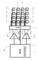
- FIG. 1 is a diagram showing a main part of an electric stimulation device 100 according to an embodiment of the present invention.
- This electrostimulation apparatus 100 includes a plurality of electrodes 1 arranged in a matrix, two output units 2, an output selection unit 3 provided between the two output units 2 and a plurality of electrodes 1, and the whole. And a control unit 4 for controlling the above.
- the output selection unit 3 includes an output terminal P1 (P1 1 , P1 2 ) on the high potential side and an output terminal P2 (P2 1 on the low potential side) of the output unit 2 (2-1, 2-2). , P2 2 ), the combination of the electrodes 1 forming an electrode pair connected between the electrodes 1 and P2 2 ) can be arbitrarily switched.
- the output selection unit 3 is composed of a large number of switching elements such as transistors. By switching the connection mode of the switching elements, the output terminal P1 (P1 1 , P1 2 ) on the high potential side and the low potential side are output. The combination of the electrodes 1 connected to the output terminals P2 (P2 1 , P2 2 ) can be arbitrarily switched.
- control unit 4 controls the output unit 2 (2-1, 2-2) at the high potential side output end P1 (P1 1 , P1 2 ) and the low potential side output end P2 (P2 1 , P2 2 ) is provided with a function of sending a signal (hereinafter, referred to as a selection signal) for instructing a combination of the electrodes 1 connected to the output selection unit 3.
- a selection signal a signal for instructing a combination of the electrodes 1 connected to the output selection unit 3.
- control unit 4 is realized by hardware including a processor and a storage device and a program that realizes various functions in cooperation with these hardware.
- the control unit 4 When presenting information such as characters displayed on the display to the wearer, the control unit 4 outputs a signal indicating the information to the output selection unit 3 as a selection signal.
- the output selection unit 3 connects the electrodes 1-1 and 1-2 to the high-potential-side output end P1 1 of the output unit 2-1 as shown in FIG.
- the electrodes 1-11, 1-12, 1-15, and 1-16 are connected to the output terminal P2 1 on the low potential side of the output section 2-1.
- the electrodes 1-1 and 1-2 become equipotential surfaces, and the two electrodes 1-1 and 1-2 form one large positive electrode. Further, the electrodes 1-11, 1-12, 1-15, and 1-16 become equipotential surfaces, and the four electrodes 1-11, 1-12, 1-15, and 1-16 form one large negative electrode. Is made.
- the combination of the electrodes 1-1 and 1-2 is used as the positive electrode between the high-potential-side output end P1 1 and the low-potential-side output end P2 1 of the output section 2-1.
- An electrode pair is formed using the combination of 11, 1-12, 1-15, and 1-16 as the negative electrode, and a current flows through this electrode pair through the wearer's body.
- the output selection unit 3 connects the electrode 1-9 to the output terminal P1 2 on the high potential side of the output unit 2-2 as shown in FIG.
- the electrode 1-14 is connected to the low-potential side output terminal P2 2 .
- one electrode 1-9 forms a positive electrode
- one electrode 1-14 forms a negative electrode. That is, between the high-potential-side output end P1 1 and the low-potential-side output end P2 1 of the output section 2-1, the electrode 1-9 serves as the plus-side electrode and the electrode 1-14 serves as the minus-side electrode. An electrode pair is created, and a current flows through the electrode pair through the wearer's body. This changes the sensation given to the wearer.
- the output terminal P2 (P2 1 , P2 2 ) on the low potential side are dynamically switched between combinations of the electrodes 1 forming the electrode pair, and the output unit 2 (2-1, 2- Change the number of electrodes connected to 2) (effective electrode area), change the position of electrodes connected to the output section 2 (2-1, 2-2) (effective electrode arrangement), etc. Will be able to do freely.
- the arrangement of the electrodes specifically, the distance between the electrodes through which an electric current is passed, it is possible to change the penetration depth and range of the applied electric signal into the body.
- the shape of the electrodes connected to the output unit 2 can be changed by changing the number and positions of the electrodes connected to the output unit 2.
- the number of electrodes 1 is 16 and the number of output units 2 is 2.
- the number is not limited to this, and the number of output units 2 may be one.
- an instruction from the control unit 4 to the output selection unit 3 creates a current flow from the electrode b1 to the electrode a1 shown in FIG. 8 or from the electrode b1 to the electrode b3 shown in FIG. It is also possible to create a current flow. Further, by issuing an instruction from the control unit 4 to the output selection unit 3, the electrode pairs connected to the output unit 2 can be switched at high speed with the electrodes 1-1 to 1-16 still attached. it can.
- the output end P1 of the output unit 2 is the high-potential side output end and the output end P2 of the output unit 2 is the low-potential side output end.
- the polarities of P2 and P2 may be switched. That is, at a certain timing, the output end P1 of the output unit 2 is set to a high potential and the output end P2 is set to a low potential, and at a certain timing, the output end P1 of the output unit 2 is set to a low potential and the output end P2 is set to a high potential.
- a configuration may be adopted in which bipolar potentials (AC signals) are output from the output terminals P1 and P2.
- control unit 4 may be provided with a functional unit that inspects the contact state between the electrode 1 and the place (skin) where the electrode 1 is installed.
- FIG. 4 shows an example in which the control section 4 is provided with a contact state inspection section 41 as a functional section for inspecting the contact state between the electrode 1 and the skin.
- the contact state inspection unit 41 is provided as one of the functions realized by the cooperation of the hardware and the program in the control unit 4, and for each of the electrodes 1-1 to 1-16, the contact between the electrode and the skin is performed. A process of inspecting the contact state between the electrodes and excluding the electrode determined to be in the poor contact state from the combination of electrodes instructing the output selection unit 3 is performed.
- the contact state between the electrode 1 and the skin can be known by applying a weaker electric current than usual, which is too weak for the wearer to feel.
- the contact state inspection unit 41 sends, for example, a command for flowing a weak current to the output unit 2-1, and also between the high-potential-side output end P1 1 and the low-potential-side output end P2 1 of the output unit 2-1.
- the combination of electrode pairs to be created is switched in order such as “#01-#02”, “#02-#03”,... “#15-#16”, “#16-#01”.
- An instruction to go is sent to the output selection unit 3.
- the combination of electrode pairs is switched to "#01-#02", “#02-#03",... "#15-#16", “#16-#01".
- the respective current amounts at that time are acquired from the output unit 2-1, and the contact state with the skin of each of the electrodes 1-1 to 1-16 is determined from the acquired current amounts.
- the contact state inspection unit 41 scrutinizes the vicinity of a portion determined to have a poor contact state. Since the electrodes 1 form one closed circuit as a pair, for example, when there is a problem with the electrode 1-2, there is a problem between the electrodes 1-1 and 1-2 and between the electrodes 1-2 and 1-3. Should happen. Therefore, it can be seen that the location where the problem occurs is an environment where the contact state between the electrode and the skin is poor and is not suitable for use.
- the contact state inspection unit 41 excludes an electrode determined to have a poor contact state with the skin from the combination of electrodes instructing the output selection unit 3. This prevents selection of electrodes that are not in contact with the skin.
- Electrode 1 (1-1 to 1-16)... Electrode, 2 (2-1, 2-2)... Output unit, 3... Output selection unit, 4... Control unit, 41... Contact state inspection unit, P1 (P1 1 , P1 2 )... High potential side output end, P2 (P2 1 , P2 2 )... Low potential side output end, 100... Electrostimulator.
Landscapes
- Health & Medical Sciences (AREA)
- Life Sciences & Earth Sciences (AREA)
- Engineering & Computer Science (AREA)
- Biomedical Technology (AREA)
- Nuclear Medicine, Radiotherapy & Molecular Imaging (AREA)
- Radiology & Medical Imaging (AREA)
- Animal Behavior & Ethology (AREA)
- General Health & Medical Sciences (AREA)
- Public Health (AREA)
- Veterinary Medicine (AREA)
- General Physics & Mathematics (AREA)
- Biophysics (AREA)
- Heart & Thoracic Surgery (AREA)
- Physics & Mathematics (AREA)
- Electrotherapy Devices (AREA)
Abstract
1つ以上の出力部2と複数の電極1との間に出力選択部3を設ける。出力選択部3は、出力部2に接続される電極対を構成する電極1の組み合わせを任意に切り替え可能な構成とされている。制御部4から、出力選択部3へ選択信号を送り、出力部2に接続する電極対を構成する電極1の組み合わせを指示する。これにより、触覚提示の多様化を図る。
Description
本発明は、電気刺激装置に関し、特に電極間に電流を流すことによって人間の体に刺激を与える電気刺激装置に関する。
従来より、電極間に電流を流すことによって人間の体に刺激を与える電気刺激装置として、低周波治療装置や電気的筋肉刺激装置などが用いられている。
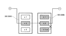
図5に、従来の電気刺激装置の一例として、特許文献1に示された低周波治療装置の要部を示す。この低周波治療装置は、治療部位に貼り付けられる1対のパッド300(300A,300B)を備えており、高電位側(プラス側)のパッド300Aには電極a1,a2,a3が設けられ、低電位側(マイナス側)のパッド300Bには電極b1,b2,b3が設けられている。
この低周波治療装置では、パッド300Aに設けられた電極a1,a2,a3が選択的に高電位とされ、パッド300Bに設けられた電極b1,b2,b3が選択的に低電位とされる。これにより、通電エリアの位置や面積を変化させるようにして、もみ刺激やさすり刺激などを作り出すことが可能となる。
例えば、図6Aに示すように、電極a1を高電位とし、電極b1を低電位とすると、電極a1からb1へ電流が流れる。この状態から、図6Bに示すように、電極b1に変えて電極b2を低電位とすると、電極a1からb2へ電流が流れるようになる。これにより、通電エリアの位置(実効的な電極の配置)が変化する。
例えば、図7Aに示すように、電極a1,a2を高電位とし、電極b1,b2を低電位とすると、電極a1,a2から電極b1,b2へ電流が流れる。この状態から、図7Bに示すように、さらに、電極a3を高電位とし、電極b3を低電位とすると、電極a3から電極b3へも電流が流れるようになる。これにより、通電エリアの面積(実効的な電極の面積)が変化する。
梶本他,"額に装着する電気触覚ディスプレイ",日本バーチャルリアリティ学会第11回大会論文集,pp.1-4,2006
しかしながら、この特許文献1に示された技術では、電極a1,a2,a3から電極b1,b2,b3への一方向への電流の流れしか変更することができない。例えば、図8に示すように、電極a1から電極b1への電流の流れを電極b1から電極a1への電流の流れに変更することはできない。また、例えば、図9に示すように、電極a2から電極b2への電流の流れに、電極b1から電極b3への電流の流れを加える、というような変更はできない。
このように、特許文献1に示された技術では、電極b1から電極a1への電流の流れを作り出したり、電極b1から電極b3への電流の流れを作り出したりすることができず、人間の体に与える刺激の多様化を図ることができない。このことは、例えば非特許文献1に示されるような電気刺激による触覚提示の分野において、特許文献1に示された技術を利用したとしても、触覚提示の多様化を図ることができないことを意味している。
本発明は、このような課題を解決するためになされたもので、その目的とするところは、電気刺激による触覚提示の分野において、触覚提示の多様化を図ることが可能な電気刺激装置を提供することにある。
このような目的を達成するために本発明は、複数の電極(1)と、電位差を生じる第1の出力端(P1)と第2の出力端(P2)とを備える1つ以上の出力部(2)と、前記出力部の第1の出力端と第2の出力端との間に接続される電極対を構成する前記電極の組み合わせを任意に切り替え可能な構成とされた出力選択部(3)とを備えることを特徴とする。
本発明では、出力部の第1の出力端と第2の出力端との間に接続される電極対(以下、単に出力部に接続される電極対と呼ぶ。)を構成する電極の組み合わせを任意に切り替えることが可能である。これにより、出力部に接続される電極対を構成する電極の組み合わせを動的に切り替えるようにして、出力部に接続される電極の数(実効的な電極の面積)の変更や出力部に接続される電極の位置(実効的な電極の配置)の変更などを自由に行うことができるようになる。
本発明の一構成例として、制御部から出力選択部に対して、出力部に接続する電極対を構成する電極の組み合わせを指示するようにし、出力部に接続される電極の数や出力部に接続される電極の位置を変更させたりすることが考えられる。
また、本発明の一構成例として、制御部に、複数の電極のそれぞれについて、その電極とその電極が設置された箇所との間の接触状態を検査し、接触状態が悪いと判断した電極を出力選択部に対して指示する電極の組み合わせから除外する機能部を設けるようにすることも考えられる。
なお、上記説明では、一例として、発明の構成要素に対応する図面上の構成要素を、括弧を付した参照符号によって示している。
以上説明したように、本発明によれば、出力部に接続される電極対を構成する電極の組み合わせ任意に切り替えることができるようにしたので、出力部に接続される電極の数(実効的な電極の面積)の変更や出力部に接続される電極の位置(実効的な電極の配置)の変更などを自由に行うことができるようになり、電気刺激による触覚提示の分野において、触覚提示の多様化を図ることが可能となる。
以下、本発明の実施の形態を図面に基づいて詳細に説明する。図1は本発明の実施の形態に係る電気刺激装置100の要部を示す図である。
この電気刺激装置100は、マトリックス状に配置された複数の電極1と、2つの出力部2と、2つの出力部2と複数の電極1との間に設けられた出力選択部3と、全体の制御を行う制御部4とを備えている。
出力部2は、高電位側(プラス側)の電位の出力端P1と低電位側(マイナス側)の電位の出力端P2とを備えており、制御部2からの指令を受けて動作する。本実施の形態では、2つの出力部2のうち一方を出力部2-1(#DRV1)とし、他方を出力部2-2(#DRV2)とする。以下、出力端P1を高電位側の出力端、出力端P2を低電位側の出力端と呼ぶ。
本実施の形態において、複数の電極1は電極1-1~1-16の16個とされ、この電極1-1~1-16が縦4列、横4列として、互いに独立して配置されている。この電極1-1~1-16は、パッド上に設けられ、利用者の体に装着される。以下、電極1-1~1-16を示す番号を#01~#16とする。
本実施の形態において、出力選択部3は、出力部2(2-1,2-2)の高電位側の出力端P1(P11,P12)と低電位側の出力端P2(P21,P22)との間に接続される電極対を構成する電極1の組合せを任意に切り替え可能な構成とされている。例えば、出力選択部3は、トランジスタなどの多数のスイッチング素子により構成されており、このスイッチング素子の接続モードを切り替えることによって、高電位側の出力端P1(P11,P12)および低電位側の出力端P2(P21,P22)に接続される電極1の組み合わせを、任意に切り替えることができるようになっている。
また、本実施の形態において、制御部4は、出力部2(2-1,2-2)の高電位側の出力端P1(P11,P12)および低電位側の出力端P2(P21,P22)に接続する電極1の組み合わせを指示する信号(以下、この信号を選択信号と呼ぶ。)を出力選択部3へ送る機能を備えている。
本実施の形態において、制御部4は、プロセッサや記憶装置からなるハードウェアと、これらのハードウェアと協働して各種機能を実現させるプログラムとによって実現される。以下、制御部4からの選択信号に従う出力選択部3における動作について、具体例を挙げて説明する。なお、制御部4は、例えばディスプレイに表示されている文字などの情報を装着者に提示するような場合、その情報を示す信号を選択信号として出力選択部3に出力する。
〔具体例1〕
制御部4より、例えば、出力部2-1の高電位側の出力端P11に接続する電極1の組み合わせとして「#01,#02」を、出力部2-1の低電位側の出力端P21に接続する電極1の組み合わせとして「#11,#12,#15,#16」を指示する選択信号が、出力選択部3へ送られたとする。
制御部4より、例えば、出力部2-1の高電位側の出力端P11に接続する電極1の組み合わせとして「#01,#02」を、出力部2-1の低電位側の出力端P21に接続する電極1の組み合わせとして「#11,#12,#15,#16」を指示する選択信号が、出力選択部3へ送られたとする。
この選択信号が送られてくると、出力選択部3は、図2に示すように、出力部2-1の高電位側の出力端P11に電極1-1,1-2を接続し、出力部2-1の低電位側の出力端P21に電極1-11,1-12,1-15,1-16を接続する。
これにより、電極1-1,1-2が等電位面となり、2つの電極1-1,1-2で1つの大きなプラス側の電極が作られる。また、電極1-11,1-12,1-15,1-16が等電位面となり、4つの電極1-11,1-12,1-15,1-16で1つの大きなマイナス側の電極が作られる。
すなわち、出力部2-1の高電位側の出力端P11と低電位側の出力端P21との間に、電極1-1,1-2の組み合わせをプラス側の電極とし、電極1-11,1-12,1-15,1-16の組み合わせをマイナス側の電極とする電極対が作られ、この電極対に装着者の体を通して電流が流れるものとなる。
なお、選択された電極以外のその他の電極はどこにも接続されずに、フローティング状態となる。このため、出力に影響を及ぼすことはない。下記の具体例2でも同じである。
〔具体例2〕
次に、制御部4より、さらに、出力部2-2の高電位側の出力端P12に接続する電極1の組み合わせとして「#09」を、出力部2-2の低電位側の出力端P22に接続する電極1の組み合わせとして「#14」を指示する選択信号が、出力選択部3へ送られたとする。
次に、制御部4より、さらに、出力部2-2の高電位側の出力端P12に接続する電極1の組み合わせとして「#09」を、出力部2-2の低電位側の出力端P22に接続する電極1の組み合わせとして「#14」を指示する選択信号が、出力選択部3へ送られたとする。
この選択信号が送られてくると、出力選択部3は、図3に示すように、出力部2-2の高電位側の出力端P12に電極1-9を接続し、出力部2-2の低電位側の出力端P22に電極1-14を接続する。
これにより、1つの電極1-9でプラス側の電極が作られ、1つの電極1-14でマイナス側の電極が作られる。すなわち、出力部2-1の高電位側の出力端P11と低電位側の出力端P21との間に、電極1-9をプラス側の電極とし、電極1-14をマイナス側の電極とする電極対が作られ、この電極対に装着者の体を通して電流が流れるものとなる。これにより、装着者に与えられる感覚が変化する。
この具体例1,2からも分かるように、本実施の形態の電気刺激装置100では、出力部2(2-1,2-2)の高電位側の出力端P1(P11,P12)と低電位側の出力端P2(P21,P22)との間に接続される電極対を構成する電極1の組み合わせを動的に切り替えるようにして、出力部2(2-1,2-2)に接続される電極の数(実効的な電極の面積)の変更や出力部2(2-1,2-2)に接続される電極の位置(実効的な電極の配置)の変更などを自由に行うことができるようになる。例えば、電極の配置、具体的には電流を流す電極間の距離を変更することで、印加する電気信号の体内への侵入深さや、範囲を変更することができる。また、出力部2に接続される電極の数や位置を変えることによって、出力部2に接続される電極の形状も変えることができる。このようにして、本実施の形態によれば、電気刺激による触覚提示の分野において、触覚提示の多様化を図ることが可能となる。
上述した実施の形態では、電極1の数を16個とし、出力部2の数を2個としたが、これに限られるものではなく、出力部2は1つであっても構わない。電極1の数や出力部2の数を多くすることにより、多様な制御が可能となる。しかし、電極1は必ずペアで利用しない限り閉ループが形成できないため、電流が装着者に流れることがない。そのため、電極1の数をeとし、出力部2の数をdとすると、e ≧ 2dで用いることが望ましい。本実施の形態では、制御部4からの出力選択部3に対する指示により、図8に示した電極b1から電極a1への電流の流れを作り出したり、図9に示した電極b1から電極b3への電流の流れを作り出すことも可能である。また、制御部4から出力選択部3へ指示を出すことにより、電極1-1~1-16を装着したままの状態で、出力部2に接続される電極対の切り替えを高速に行うことができる。
また、上述した実施の形態では、出力部2の出力端P1を高電位側の出力端とし、出力部2の出力端P2を低電位側の出力端としたが、出力部2の出力端P1とP2の極性が入れ替わるような構成をとるようにしてもよい。すなわち、あるタイミングでは、出力部2の出力端P1を高電位、出力端P2を低電位とし、あるタイミングでは、出力部2の出力端P1を低電位、出力端P2を高電位とするというように、出力端P1,P2から両極性の電位(交流的な信号)を出力するような構成をとるようにしてもよい。
また、上述した実施の形態において、制御部4に、電極1とその電極1が設置された箇所(皮膚)との間の接触状態を検査する機能部を設けるようにしてもよい。図4に、制御部4に、電極1と皮膚との間の接触状態の検査を行う機能部として接触状態検査部41を設けた例を示す。
この接触状態検査部41は、制御部4におけるハードウェアとプログラムとの協働によって実現される機能の1つとして設けられ、電極1-1~1-16のそれぞれについて、その電極と皮膚との間の接触状態を検査し、接触状態が悪いと判断した電極を出力選択部3に対して指示する電極の組み合わせから除外する処理を行う。
電極1と皮膚との間の接触状態は、装着者が感じ取れないほどの通常より弱い微弱電流を流すことで知ることができる。接触状態検査部41は、例えば出力部2-1に微弱電流を流す指令を送るとともに、出力部2-1の高電位側の出力端P11と低電位側の出力端P21との間に作られる電極対の組み合わせを、「#01-#02」、「#02-#03」、・・・・「#15-#16」、「#16-#01」というように、順番に切り替えて行く指示を出力選択部3へ送る。
接触状態検査部41は、電極対の組み合わせが「#01-#02」、「#02-#03」、・・・・「#15-#16」、「#16-#01」と切り替えられた時の各電流量を出力部2-1から取得し、この取得した各電流量から電極1-1~1-16のそれぞれについて皮膚との間の接触状態を判断する。
この場合、接触状態検査部41は、接触状態が悪いと判断した箇所については、その周辺を精査する。電極1はペアで1つの閉回路となるため、例えば電極1-2で問題があった場合は電極1-1と1-2との間、電極1-2と1-3との間で問題が起こるはずである。よって、問題が起こった箇所が電極と皮膚との間の接触状態が悪く利用に適していない環境であることが分かる。
接触状態検査部41は、皮膚との間の接触状態が悪いと判断した電極があった場合、その電極を出力選択部3に対して指示する電極の組み合わせから除外する。これにより、皮膚に接触していない状態の電極が選択されることが防がれる。
〔実施の形態の拡張〕
以上、実施の形態を参照して本発明を説明したが、本発明は上記の実施の形態に限定されるものではない。本発明の構成や詳細には、本発明の技術思想の範囲内で当業者が理解し得る様々な変更をすることができる。
以上、実施の形態を参照して本発明を説明したが、本発明は上記の実施の形態に限定されるものではない。本発明の構成や詳細には、本発明の技術思想の範囲内で当業者が理解し得る様々な変更をすることができる。
1(1-1~1-16)…電極、2(2-1,2-2)…出力部、3…出力選択部、4…制御部、41…接触状態検査部、P1(P11,P12)…高電位側の出力端、P2(P21,P22)…低電位側の出力端、100…電気刺激装置。
Claims (5)
- 複数の電極と、
電位差を生じる第1の出力端と第2の出力端とを備える1つ以上の出力部と、
前記出力部の第1の出力端と第2の出力端との間に接続される電極対を構成する前記電極の組み合わせを任意に切り替え可能な構成とされた出力選択部と
を備えることを特徴とする電気刺激装置。 - 請求項1に記載された電気刺激装置において、
前記出力部の第1の出力端と第2の出力端との間に接続する電極対を構成する前記電極の組み合わせを前記出力選択部に対して指示する制御部
をさらに備えることを特徴とする電気刺激装置。 - 請求項2に記載された電気刺激装置において、
前記制御部は、
前記出力部の第1の出力端に接続される前記電極の数および前記出力部の第2の出力端に接続される前記電極の数を変更する
ことを特徴とする電気刺激装置。 - 請求項2に記載された電気刺激装置において、
前記制御部は、
前記出力部の第1の出力端に接続される前記電極の位置および前記出力部の第2の出力端に接続される前記電極の位置を変更する
ことを特徴とする電気刺激装置。 - 請求項2~4の何れか1項に記載された電気刺激装置において、
前記制御部は、
前記複数の電極のそれぞれについて、その電極とその電極が設置された箇所との間の接触状態を検査し、接触状態が悪いと判断した電極を前記出力選択部に対して指示する前記電極の組み合わせから除外する接触状態検査部
を備えることを特徴とする電気刺激装置。
Priority Applications (1)
| Application Number | Priority Date | Filing Date | Title |
|---|---|---|---|
| US17/291,011 US20210402183A1 (en) | 2018-12-11 | 2019-11-27 | Electrostimulation Device |
Applications Claiming Priority (2)
| Application Number | Priority Date | Filing Date | Title |
|---|---|---|---|
| JP2018-231358 | 2018-12-11 | ||
| JP2018231358A JP2020092762A (ja) | 2018-12-11 | 2018-12-11 | 電気刺激装置 |
Publications (1)
| Publication Number | Publication Date |
|---|---|
| WO2020121816A1 true WO2020121816A1 (ja) | 2020-06-18 |
Family
ID=71076384
Family Applications (1)
| Application Number | Title | Priority Date | Filing Date |
|---|---|---|---|
| PCT/JP2019/046372 Ceased WO2020121816A1 (ja) | 2018-12-11 | 2019-11-27 | 電気刺激装置 |
Country Status (3)
| Country | Link |
|---|---|
| US (1) | US20210402183A1 (ja) |
| JP (1) | JP2020092762A (ja) |
| WO (1) | WO2020121816A1 (ja) |
Cited By (1)
| Publication number | Priority date | Publication date | Assignee | Title |
|---|---|---|---|---|
| WO2022045051A1 (ja) * | 2020-08-24 | 2022-03-03 | 株式会社Mtg | 電気刺激装置 |
Families Citing this family (5)
| Publication number | Priority date | Publication date | Assignee | Title |
|---|---|---|---|---|
| JP7235005B2 (ja) * | 2020-05-27 | 2023-03-08 | 株式会社三洋物産 | 遊技機 |
| JP7235007B2 (ja) * | 2020-05-27 | 2023-03-08 | 株式会社三洋物産 | 遊技機 |
| JP7235006B2 (ja) * | 2020-05-27 | 2023-03-08 | 株式会社三洋物産 | 遊技機 |
| JP7298546B2 (ja) * | 2020-05-27 | 2023-06-27 | 株式会社三洋物産 | 遊技機 |
| JP7235004B2 (ja) * | 2020-05-27 | 2023-03-08 | 株式会社三洋物産 | 遊技機 |
Citations (5)
| Publication number | Priority date | Publication date | Assignee | Title |
|---|---|---|---|---|
| JPH05337203A (ja) * | 1992-06-04 | 1993-12-21 | Nec San-Ei Instr Co Ltd | 電気刺激装置 |
| JP2014104248A (ja) * | 2012-11-29 | 2014-06-09 | Nidek Co Ltd | 半導体回路及び該半導体回路を備える生体組織刺激装置 |
| JP2016147103A (ja) * | 2010-05-18 | 2016-08-18 | ゾール メディカル コーポレイションZOLL Medical Corporation | 複数の検知電極を備えた着用可能な携行型医療装置 |
| WO2017155085A1 (ja) * | 2016-03-10 | 2017-09-14 | H2L株式会社 | 電気刺激装置及び電気刺激システム |
| WO2017173493A1 (en) * | 2016-04-05 | 2017-10-12 | Saluda Medical Pty Ltd | Improved feedback control of neuromodulation |
Family Cites Families (9)
| Publication number | Priority date | Publication date | Assignee | Title |
|---|---|---|---|---|
| JPH0984885A (ja) * | 1995-09-22 | 1997-03-31 | Nippon Medics:Kk | 治療装置 |
| US6516227B1 (en) * | 1999-07-27 | 2003-02-04 | Advanced Bionics Corporation | Rechargeable spinal cord stimulator system |
| JP4360497B2 (ja) * | 2005-03-09 | 2009-11-11 | 国立大学法人 東京大学 | 電気触覚提示装置及び電気触覚提示方法 |
| US8620452B2 (en) * | 2006-06-30 | 2013-12-31 | Medtronic, Inc. | Selecting electrode combinations for stimulation therapy |
| FR2922460B1 (fr) * | 2007-10-22 | 2011-11-18 | Centre Nat Rech Scient | "dispositif de stimulation d'un tissu vivant par microelectrodes,ses modules amovibles et utilisation" |
| US9630012B2 (en) * | 2015-08-06 | 2017-04-25 | Meagan Medical, Inc. | Spinal cord stimulation with interferential current |
| CN109310874B (zh) * | 2016-06-08 | 2021-07-23 | 阿莫善斯有限公司 | 一种皮肤美容装置 |
| US10525268B2 (en) * | 2016-08-23 | 2020-01-07 | Medtronic, Inc. | Delivery of independent interleaved programs to produce higher-frequency electrical stimulation therapy |
| GB2572439A (en) * | 2018-03-29 | 2019-10-02 | Bio Medical Res Limited | Electrode contact monitoring |
-
2018
- 2018-12-11 JP JP2018231358A patent/JP2020092762A/ja active Pending
-
2019
- 2019-11-27 US US17/291,011 patent/US20210402183A1/en not_active Abandoned
- 2019-11-27 WO PCT/JP2019/046372 patent/WO2020121816A1/ja not_active Ceased
Patent Citations (5)
| Publication number | Priority date | Publication date | Assignee | Title |
|---|---|---|---|---|
| JPH05337203A (ja) * | 1992-06-04 | 1993-12-21 | Nec San-Ei Instr Co Ltd | 電気刺激装置 |
| JP2016147103A (ja) * | 2010-05-18 | 2016-08-18 | ゾール メディカル コーポレイションZOLL Medical Corporation | 複数の検知電極を備えた着用可能な携行型医療装置 |
| JP2014104248A (ja) * | 2012-11-29 | 2014-06-09 | Nidek Co Ltd | 半導体回路及び該半導体回路を備える生体組織刺激装置 |
| WO2017155085A1 (ja) * | 2016-03-10 | 2017-09-14 | H2L株式会社 | 電気刺激装置及び電気刺激システム |
| WO2017173493A1 (en) * | 2016-04-05 | 2017-10-12 | Saluda Medical Pty Ltd | Improved feedback control of neuromodulation |
Cited By (3)
| Publication number | Priority date | Publication date | Assignee | Title |
|---|---|---|---|---|
| WO2022045051A1 (ja) * | 2020-08-24 | 2022-03-03 | 株式会社Mtg | 電気刺激装置 |
| JP2022036444A (ja) * | 2020-08-24 | 2022-03-08 | 株式会社 Mtg | 電気刺激装置 |
| JP7573390B2 (ja) | 2020-08-24 | 2024-10-25 | 株式会社 Mtg | 電気刺激装置 |
Also Published As
| Publication number | Publication date |
|---|---|
| US20210402183A1 (en) | 2021-12-30 |
| JP2020092762A (ja) | 2020-06-18 |
Similar Documents
| Publication | Publication Date | Title |
|---|---|---|
| WO2020121816A1 (ja) | 電気刺激装置 | |
| Aoyama et al. | Four-pole galvanic vestibular stimulation causes body sway about three axes | |
| US10269223B2 (en) | Haptic communication apparatus and method | |
| US20030093133A1 (en) | Method and apparatus for electrical stimulation | |
| JP6667810B2 (ja) | 触覚提示装置 | |
| US20210220646A1 (en) | Noninvasive electric brain stimulation system | |
| CN102805900B (zh) | 用于产生人工电触觉的电刺激系统 | |
| JP2019534131A5 (ja) | ||
| KR102170138B1 (ko) | 인간 피험자의 전정 활동을 억제하기 위한 시스템 및 방법 | |
| JP6499335B2 (ja) | 複数の電極の静電摩擦効果の生成を制御する方法及び装置 | |
| CN101495181A (zh) | 低频治疗仪及其控制方法 | |
| CN106200895B (zh) | 触觉提示装置及触觉提示装置的驱动方法 | |
| CN101495180A (zh) | 低频治疗仪及其控制方法 | |
| Bahmer et al. | New parallel stimulation strategies revisited: effect of synchronous multi electrode stimulation on rate discrimination in cochlear implant users | |
| JP3204183U (ja) | 低周波治療器 | |
| TW200831150A (en) | Low-frequency electric therapy apparatus | |
| JP4910652B2 (ja) | 低周波治療器 | |
| JP2018055659A (ja) | 触覚提示装置及びその制御方法 | |
| JP2018038514A (ja) | 電気治療器 | |
| CN115463342A (zh) | 按摩设备控制方法及相关设备 | |
| EA200601337A1 (ru) | Игровой автомат | |
| KR102768160B1 (ko) | 음원과 연동된 저주파 자극을 생성할 수 있는 저주파 자극 생성 장치 및 방법 | |
| CN115970154A (zh) | 按摩设备和信号输出方法 | |
| KR20240105731A (ko) | 고령층 및 건강취약 계층의 근력운동, 치료 및 피로개선을 위한 전기적 근육 자극 기능을 구비하는 스파 시스템 | |
| Deiana et al. | Characterization of electrotactile stimulation intensity to exploit the funneling illusion |
Legal Events
| Date | Code | Title | Description |
|---|---|---|---|
| 121 | Ep: the epo has been informed by wipo that ep was designated in this application |
Ref document number: 19895928 Country of ref document: EP Kind code of ref document: A1 |
|
| NENP | Non-entry into the national phase |
Ref country code: DE |
|
| 122 | Ep: pct application non-entry in european phase |
Ref document number: 19895928 Country of ref document: EP Kind code of ref document: A1 |