WO2020122169A1 - 空気入りタイヤ - Google Patents
空気入りタイヤ Download PDFInfo
- Publication number
- WO2020122169A1 WO2020122169A1 PCT/JP2019/048653 JP2019048653W WO2020122169A1 WO 2020122169 A1 WO2020122169 A1 WO 2020122169A1 JP 2019048653 W JP2019048653 W JP 2019048653W WO 2020122169 A1 WO2020122169 A1 WO 2020122169A1
- Authority
- WO
- WIPO (PCT)
- Prior art keywords
- tire
- pneumatic tire
- rim
- belt
- vehicle
- Prior art date
- Legal status (The legal status is an assumption and is not a legal conclusion. Google has not performed a legal analysis and makes no representation as to the accuracy of the status listed.)
- Ceased
Links
Images





Classifications
-
- B—PERFORMING OPERATIONS; TRANSPORTING
- B60—VEHICLES IN GENERAL
- B60C—VEHICLE TYRES; TYRE INFLATION; TYRE CHANGING; CONNECTING VALVES TO INFLATABLE ELASTIC BODIES IN GENERAL; DEVICES OR ARRANGEMENTS RELATED TO TYRES
- B60C9/00—Reinforcements or ply arrangement of pneumatic tyres
- B60C9/02—Carcasses
- B60C9/04—Carcasses the reinforcing cords of each carcass ply arranged in a substantially parallel relationship
- B60C9/08—Carcasses the reinforcing cords of each carcass ply arranged in a substantially parallel relationship the cords extend transversely from bead to bead, i.e. radial ply
-
- B—PERFORMING OPERATIONS; TRANSPORTING
- B60—VEHICLES IN GENERAL
- B60C—VEHICLE TYRES; TYRE INFLATION; TYRE CHANGING; CONNECTING VALVES TO INFLATABLE ELASTIC BODIES IN GENERAL; DEVICES OR ARRANGEMENTS RELATED TO TYRES
- B60C3/00—Tyres characterised by the transverse section
- B60C3/04—Tyres characterised by the transverse section characterised by the relative dimensions of the section, e.g. low profile
-
- B—PERFORMING OPERATIONS; TRANSPORTING
- B60—VEHICLES IN GENERAL
- B60C—VEHICLE TYRES; TYRE INFLATION; TYRE CHANGING; CONNECTING VALVES TO INFLATABLE ELASTIC BODIES IN GENERAL; DEVICES OR ARRANGEMENTS RELATED TO TYRES
- B60C5/00—Inflatable pneumatic tyres or inner tubes
-
- B—PERFORMING OPERATIONS; TRANSPORTING
- B60—VEHICLES IN GENERAL
- B60C—VEHICLE TYRES; TYRE INFLATION; TYRE CHANGING; CONNECTING VALVES TO INFLATABLE ELASTIC BODIES IN GENERAL; DEVICES OR ARRANGEMENTS RELATED TO TYRES
- B60C9/00—Reinforcements or ply arrangement of pneumatic tyres
- B60C9/0007—Reinforcements made of metallic elements, e.g. cords, yarns, filaments or fibres made from metal
-
- B—PERFORMING OPERATIONS; TRANSPORTING
- B60—VEHICLES IN GENERAL
- B60C—VEHICLE TYRES; TYRE INFLATION; TYRE CHANGING; CONNECTING VALVES TO INFLATABLE ELASTIC BODIES IN GENERAL; DEVICES OR ARRANGEMENTS RELATED TO TYRES
- B60C9/00—Reinforcements or ply arrangement of pneumatic tyres
- B60C9/18—Structure or arrangement of belts or breakers, crown-reinforcing or cushioning layers
- B60C9/20—Structure or arrangement of belts or breakers, crown-reinforcing or cushioning layers built-up from rubberised plies each having all cords arranged substantially parallel
- B60C9/2003—Structure or arrangement of belts or breakers, crown-reinforcing or cushioning layers built-up from rubberised plies each having all cords arranged substantially parallel characterised by the materials of the belt cords
- B60C9/2009—Structure or arrangement of belts or breakers, crown-reinforcing or cushioning layers built-up from rubberised plies each having all cords arranged substantially parallel characterised by the materials of the belt cords comprising plies of different materials
-
- B—PERFORMING OPERATIONS; TRANSPORTING
- B60—VEHICLES IN GENERAL
- B60C—VEHICLE TYRES; TYRE INFLATION; TYRE CHANGING; CONNECTING VALVES TO INFLATABLE ELASTIC BODIES IN GENERAL; DEVICES OR ARRANGEMENTS RELATED TO TYRES
- B60C9/00—Reinforcements or ply arrangement of pneumatic tyres
- B60C9/18—Structure or arrangement of belts or breakers, crown-reinforcing or cushioning layers
- B60C9/20—Structure or arrangement of belts or breakers, crown-reinforcing or cushioning layers built-up from rubberised plies each having all cords arranged substantially parallel
- B60C9/22—Structure or arrangement of belts or breakers, crown-reinforcing or cushioning layers built-up from rubberised plies each having all cords arranged substantially parallel the plies being arranged with all cords disposed along the circumference of the tyre
- B60C9/2204—Structure or arrangement of belts or breakers, crown-reinforcing or cushioning layers built-up from rubberised plies each having all cords arranged substantially parallel the plies being arranged with all cords disposed along the circumference of the tyre obtained by circumferentially narrow strip winding
-
- B—PERFORMING OPERATIONS; TRANSPORTING
- B60—VEHICLES IN GENERAL
- B60C—VEHICLE TYRES; TYRE INFLATION; TYRE CHANGING; CONNECTING VALVES TO INFLATABLE ELASTIC BODIES IN GENERAL; DEVICES OR ARRANGEMENTS RELATED TO TYRES
- B60C9/00—Reinforcements or ply arrangement of pneumatic tyres
- B60C9/02—Carcasses
- B60C9/04—Carcasses the reinforcing cords of each carcass ply arranged in a substantially parallel relationship
- B60C2009/0416—Physical properties or dimensions of the carcass cords
- B60C2009/0425—Diameters of the cords; Linear density thereof
-
- B—PERFORMING OPERATIONS; TRANSPORTING
- B60—VEHICLES IN GENERAL
- B60C—VEHICLE TYRES; TYRE INFLATION; TYRE CHANGING; CONNECTING VALVES TO INFLATABLE ELASTIC BODIES IN GENERAL; DEVICES OR ARRANGEMENTS RELATED TO TYRES
- B60C9/00—Reinforcements or ply arrangement of pneumatic tyres
- B60C9/02—Carcasses
- B60C9/04—Carcasses the reinforcing cords of each carcass ply arranged in a substantially parallel relationship
- B60C2009/0416—Physical properties or dimensions of the carcass cords
- B60C2009/0441—Density in width direction
-
- B—PERFORMING OPERATIONS; TRANSPORTING
- B60—VEHICLES IN GENERAL
- B60C—VEHICLE TYRES; TYRE INFLATION; TYRE CHANGING; CONNECTING VALVES TO INFLATABLE ELASTIC BODIES IN GENERAL; DEVICES OR ARRANGEMENTS RELATED TO TYRES
- B60C9/00—Reinforcements or ply arrangement of pneumatic tyres
- B60C9/02—Carcasses
- B60C9/04—Carcasses the reinforcing cords of each carcass ply arranged in a substantially parallel relationship
- B60C2009/0416—Physical properties or dimensions of the carcass cords
- B60C2009/0466—Twist structures
-
- B—PERFORMING OPERATIONS; TRANSPORTING
- B60—VEHICLES IN GENERAL
- B60C—VEHICLE TYRES; TYRE INFLATION; TYRE CHANGING; CONNECTING VALVES TO INFLATABLE ELASTIC BODIES IN GENERAL; DEVICES OR ARRANGEMENTS RELATED TO TYRES
- B60C9/00—Reinforcements or ply arrangement of pneumatic tyres
- B60C9/18—Structure or arrangement of belts or breakers, crown-reinforcing or cushioning layers
- B60C9/26—Folded plies
- B60C9/263—Folded plies further characterised by an endless zigzag configuration in at least one belt ply, i.e. no cut edge being present
- B60C2009/266—Folded plies further characterised by an endless zigzag configuration in at least one belt ply, i.e. no cut edge being present combined with non folded cut-belt plies
-
- B—PERFORMING OPERATIONS; TRANSPORTING
- B60—VEHICLES IN GENERAL
- B60C—VEHICLE TYRES; TYRE INFLATION; TYRE CHANGING; CONNECTING VALVES TO INFLATABLE ELASTIC BODIES IN GENERAL; DEVICES OR ARRANGEMENTS RELATED TO TYRES
- B60C2200/00—Tyres specially adapted for particular applications
- B60C2200/06—Tyres specially adapted for particular applications for heavy duty vehicles
Definitions
- the present invention relates to a small-diameter pneumatic tire with improved load bearing capacity.
- Such a small shuttle bus has a total length of about 5 m and a total width of about 2 m, and it is assumed that the total vehicle weight may exceed 3 tons. Space saving is also required for pneumatic tires mounted on such small shuttle buses.
- pneumatic tires attached to such a small shuttle bus require a high load bearing capacity that is not comparable to the conventional small diameter tires described above.
- an object of the present invention is to provide a pneumatic tire capable of achieving high space efficiency while having a higher load bearing capacity.
- One aspect of the present invention is a pneumatic tire (pneumatic tire 10) mounted on a vehicle (vehicle 1), wherein the outer diameter of the pneumatic tire is OD, and a rim wheel (rim is assembled to the pneumatic tire.
- the rim width of the wheel 100) is RW
- the tire width of the pneumatic tire is SW
- the rim diameter of the rim wheel is RD
- the OD is 350 mm or more and 600 mm or less
- 0.56 ⁇ RD/OD ⁇ 0.75 are satisfied.
- FIG. 1 is an overall schematic side view of a vehicle 1 to which a pneumatic tire 10 is attached.
- FIG. 2 is a cross-sectional view of the pneumatic tire 10 and the rim wheel 100.
- FIG. 3 is a unit cross-sectional view of the pneumatic tire 10.
- FIG. 4 is a diagram showing positioning of a typical tire size based on a combination of a tire shape (tire outer diameter OD and tire width SW) and a rim wheel shape (rim diameter RD and rim width RW).
- FIG. 5 is a sectional view of a pneumatic tire 10A according to a modification.
- FIG. 6A is a perspective view of the belt layer 50A alone during the manufacturing process.
- FIG. 6B is a perspective view of the belt layer 50A as a unit after manufacturing.
- FIG. 7 is a partial perspective view of the carcass 40 provided in the pneumatic tire 10A.
- FIG. 8 is a diagram schematically showing the cross-sectional shape of the carcass cord 40a.
- FIG. 9 is a cross-sectional view of a pneumatic tire 10B according to another modification.
- FIG. 1 is an overall schematic side view of a vehicle 1 equipped with a pneumatic tire 10 according to the present embodiment.
- the vehicle 1 is a four-wheeled vehicle.
- the vehicle 1 is not limited to four wheels, and may have a six-wheel configuration, an eight-wheel configuration, or the like.
- the vehicle 1 is equipped with a predetermined number of pneumatic tires 10 according to the wheel configuration. Specifically, the vehicle 1 is equipped with the pneumatic tire 10 assembled to the rim wheel 100 at a predetermined position.
- the new small shuttle bus belongs to a new small shuttle bus that focuses on transporting people and things in the city.
- the new small shuttle bus is assumed to be a vehicle having a total length of 4 m to 7 m, a total width of about 2 m, and a total vehicle weight of about 3 t.
- the size and the total weight of the vehicle are not necessarily limited to the range, and may be out of the range as long as they are small.
- the small shuttle bus may be used not only for transportation of people but also for transportation of goods, mobile shops, mobile offices, and the like.
- the small shuttle bus is focused on transporting people and goods in the city, so a relatively low traveling speed range (maximum speed of 70 km/h or less, average speed of about 50 km/h) is assumed. .. Therefore, the hydroplaning countermeasure does not have to be emphasized.
- the vehicle 1 is an electric vehicle having an automatic driving function (assuming level 4 or higher), but the automatic driving function is not essential and may not be an electric vehicle. Absent.
- the vehicle 1 is an electric vehicle, it is preferable to use an in-wheel motor (not shown) as a power unit.
- the in-wheel motor the entire unit may be provided in the inner space of the rim wheel 100, or a part of the unit may be provided in the inner space of the rim wheel 100.
- the vehicle 1 When using an in-wheel motor, it is preferable that the vehicle 1 has an independent steering function that allows each wheel to be independently steered. As a result, turning on the spot and lateral movement are possible, and the power transmission mechanism is not required, so that the space efficiency of the vehicle 1 can be improved.
- the pneumatic tire 10 preferably has a diameter as small as possible.
- the pneumatic tire 10 has a load bearing capacity corresponding to the total weight of the vehicle 1 while reducing the tire outer diameter OD (not shown in FIG. 1, see FIG. 2) in order to satisfy such requirements.
- the flatness of the pneumatic tire 10 is low from the viewpoint of improving responsiveness.
- the rim diameter RD of 10 (not shown in FIG. 1, see FIG. 2) is preferably large.
- FIG. 2 is a sectional view of the pneumatic tire 10 and the rim wheel 100. Specifically, FIG. 2 is a cross-sectional view along the tire width direction and tire radial direction of the pneumatic tire 10 assembled to the rim wheel 100. In FIG. 2, cross-section hatching display is omitted (the same applies to FIG. 3 and subsequent figures).
- the Pneumatic tire 10 has a relatively small diameter but is wide.
- the rim diameter RD which is the diameter of the rim wheel 100, is preferably 12 inches or more and 17.5 inches or less.
- the rim diameter RD may be 10 inches or more and 22 inches or less as long as it satisfies the other numerical range.
- the rim diameter RD is the outer diameter of the rim body of the rim wheel 100, and does not include the rim flange 110.
- the tire width SW of the pneumatic tire 10 is preferably 125 mm or more and 255 mm or less. As shown in FIG. 2, the tire width SW means the sectional width of the pneumatic tire 10, and when the pneumatic tire 10 includes a rim guard (not shown), the rim guard portion is not included.
- the flatness of the pneumatic tire 10 is preferably 35% or more and 75% or less.
- the flatness ratio is calculated using Equation 1.
- the tire outer diameter OD which is the outer diameter of the pneumatic tire 10, is 350 mm or more and 600 mm or less.
- the tire outer diameter OD is preferably 500 mm or less.
- the pneumatic tire 10 has the following formulas (2) and (3). Meet a relationship.
- the pneumatic tire 10 preferably satisfies 0.78 ⁇ RW/SW ⁇ 0.98, and more preferably 0.78 ⁇ RW/SW ⁇ 0.95. Further, the pneumatic tire 10 preferably satisfies 0.56 ⁇ RD/OD ⁇ 0.72, and more preferably 0.56 ⁇ RD/OD ⁇ 0.71.
- the pneumatic tire 10 satisfying such a relationship can have an air volume necessary for supporting the total vehicle weight of the vehicle 1 while having a small diameter.
- the air volume needs to be 20,000 cm 3 or more in consideration of load bearing performance. Also, in consideration of space saving, it is necessary to be 80,000 cm 3 or less.
- the rim width RW is not particularly limited as long as the above relationship is satisfied, but it is preferable that the rim width RW is as wide as possible from the viewpoint of securing an air volume.
- the rim width can be 3.8-7.8J.
- the ratio of the rim diameter RD to the tire outer diameter OD is small, that is, the flatness ratio is high.
- the flatness ratio is low from the viewpoint of responsiveness, and in consideration of the accommodation space such as the in-wheel motor, it is preferable that the rim diameter RD is large. Has a trade-off relationship between the air volume and the responsiveness and the accommodation space such as the in-wheel motor.
- the compatible rim width is about 7.5J.
- 215/45R12 is another example of a suitable size. In this case, the compatible rim width is about 7.0J.
- the set internal pressure (normal internal pressure) of the pneumatic tire 10 is assumed to be 400 to 1,100 kPa, and realistically 500 to 900 kPa.
- the regular internal pressure is, for example, the air pressure corresponding to the maximum load capacity of the JATMA (Japan Automobile Tire Manufacturer's Association) YearBook in Japan, and ETRTO in Europe, TRA in the US, and tire standards of other countries correspond to it.
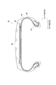
- FIG. 3 is a sectional view of the pneumatic tire 10 alone. Specifically, FIG. 3 is a cross-sectional view of the pneumatic tire 10 taken along the tire width direction and the tire radial direction.
- the pneumatic tire 10 includes a tread 20, a tire side portion 30, a carcass 40, a belt layer 50 and a bead portion 60.
- Tread 20 is the part that contacts the road surface.
- a pattern (not shown) is formed on the tread 20 according to the environment in which the pneumatic tire 10 is used and the type of vehicle on which the pneumatic tire 10 is mounted.
- the tire side part 30 is connected to the tread 20 and is located inside the tread 20 in the tire radial direction.
- the tire side portion 30 is an area from the tire width direction outer end of the tread 20 to the upper end of the bead portion 60.
- the tire side portion 30 is sometimes called a sidewall or the like.
- the carcass 40 forms the skeleton of the pneumatic tire 10.
- the carcass 40 has a radial structure in which carcass cords (not shown) radially arranged along the tire radial direction are covered with a rubber material.
- the structure is not limited to the radial structure, and may be a bias structure in which the carcass cords are arranged so as to intersect in the tire radial direction.
- the belt layer 50 is provided inside the tire in the tire radial direction of the tread 20.
- the belt layer 50 has a three-belt structure, but may have a four-belt structure.
- the belt layer 50 includes a pair of intersecting belts in which cords intersect each other.
- the structure of such a belt layer 50 is substantially the same as the structure of the belt layer of a general truck/bus tire.
- the bead portion 60 is connected to the tire side portion 30 and is located inside the tire side portion 30 in the tire radial direction.
- the bead portion 60 has an annular shape extending in the tire circumferential direction, and the carcass 40 is folded back from the tire width direction inner side to the tire width direction outer side via the bead portion 60.
- the bead portion 60 may be provided with a bead filler on the outer side in the tire radial direction of the bead core. Fur may be provided.
- FIG. 4 is a diagram showing positioning of a typical tire size based on a combination of a tire shape (tire outer diameter OD and tire width SW) and a rim wheel shape (rim diameter RD and rim width RW).
- the horizontal axis of the graph shown in FIG. 4 represents the ratio (RW/SW) of the rim width RW and the tire width SW, and the vertical axis represents the ratio of the rim diameter RD and the tire outer diameter OD (RD /OD).
- typical tire size positions are plotted according to RW/SW and RD/OD values.
- the area of truck/bus tires is low for both RW/SW and RD/OD.
- the area of tires for passenger cars or light trucks is higher in both RW/SW and RD/OD than tires for trucks and buses.
- the area A1 is included in the area A1.
- the area A1 is in the range of 0.78 ⁇ RW/SW ⁇ 0.99 and 0.56 ⁇ RD/OD ⁇ 0.75.
- Such an area A1 is positioned as an area of a new small-sized shuttle bus tire that focuses on transportation of people and goods in a city like the vehicle 1 described above.
- RD/OD in the area of new small shuttle bus tires does not differ much from RD/OD in the area of passenger car or light truck tires, and some overlap.
- RW/SW in the area of new small shuttle bus tires is higher than RW/SW in the area of passenger car or light truck tires.
- the tire outer diameter OD of the pneumatic tire 10 is 350 mm or more and 600 mm or less. Therefore, the diameter is sufficiently smaller than the size of the vehicle 1, which can contribute to space saving of the vehicle 1.
- the rim width RW with respect to the tire width SW is wide, that is, a wide tire can be configured and is high. It is easy to secure the air volume necessary to exert the load bearing capacity. Note that if the rim width RW becomes too wide, the tire width SW also widens, space efficiency decreases, and the bead portion 60 easily comes off the rim wheel 100.
- the relationship of 0.56 ⁇ RD/OD ⁇ 0.75 is satisfied, so that the rim diameter RD is large with respect to the tire outer diameter OD, and the accommodation space for the in-wheel motor etc. is secured. Easy to do.
- the rim diameter RD becomes too small, the diameter size of the disc brake or the drum brake becomes small. For this reason, the effective contact area of the brake becomes small, and it becomes difficult to secure the required braking performance.
- the rim diameter RD of the pneumatic tire 10 is preferably 12 inches or more and 17.5 inches or less. This makes it possible to secure a necessary and sufficient air volume and a storage space for the in-wheel motor while maintaining the small diameter. In addition, braking performance and driving performance can be ensured.
- the tire width SW of the pneumatic tire 10 is preferably 125 mm or more and 255 mm or less. Further, the flatness of the pneumatic tire 10 is preferably 35% or more and 75% or less. As a result, a necessary and sufficient air volume and a storage space for the in-wheel motor and the like can be secured.
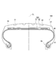
- FIG. 5 is a sectional view of a pneumatic tire 10A according to a modification.
- the pneumatic tire 10A includes a belt layer 50A.
- the belt layer 50A includes a core belt 51 and a sheath vest 52.
- the core belt 51 is provided from one shoulder portion 26 of the tread 20 to the other shoulder portion 27 of the tread 20.
- the shoulder portion 26 is an area outside the circumferential main groove 21 in the tire width direction
- the shoulder portion 27 is an area outside the circumferential main groove 22 in the tire width direction. That is, the shoulder portion 26 and the shoulder portion 27 are regions on the outer side in the tire width direction with respect to the circumferential main groove formed on the outermost side in the tire width direction.
- the core belt 51 is a belt in which a belt cord 51a (not shown in FIG. 5, see FIG. 6A) inclined at a low angle with respect to the tire width direction is covered with rubber.
- the sheath vest 52 is a tape-shaped belt including a cord, and is wrapped around the entire circumference of the core belt 51.
- Belt layer 50A provides the same function as the interlaced belt layer.
- the folded end 41 of the carcass 40 folded at the bead portion 60 is provided so as to be wound along the bead core 61.
- the folded-back end portion 41 is in contact with the tire radial outer end of the bead core 61.
- the bead portion 60 may be provided with a bead filler.
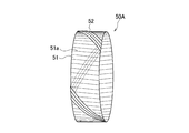
- FIG. 6A and 6B show the structure of the belt layer 50A. Specifically, FIG. 6A is a single perspective view of the belt layer 50A during manufacturing, and FIG. 6B is a single perspective view of the belt layer 50A after manufacturing.
- the core belt 51 has belt cords 51a arranged along the tire width direction.
- the core belt 51 is an annular belt formed by coating a plurality of belt cords 51a with rubber.
- the belt cord 51a is slightly inclined with respect to the tire width direction as shown in FIG. 6A. Specifically, it is preferable that the belt cord 51a is inclined in the same direction as the inclination direction of the sheath vest 52 (upward to the left in FIG. 6A).
- the sheath vest 52 is a tape-shaped belt with a width of about 1 cm, and is wound around the core belt 51 in a spiral shape along the tire circumferential direction. Specifically, the sheath vest 52 is spirally wound around the core belt 51 along the tire circumferential direction with a predetermined distance larger than the width of the sheath vest 52.
- the sheath vest 52 is wound over a plurality of turns in the tire circumferential direction so as not to overlap the adjacent sheath vests 52, so that the tire radial direction outer side surface of the core belt 51 and the tire radial direction inner side surface of the core belt 51. cover.
- the longitudinal end (not shown) of the tape-shaped sheath vest 52 is wound around the core belt 51 so as not to be located in the shoulder portions 26, 27 and the center region (immediately below the tire equator line).
- the sheath vest 52 is wound around the entire circumference of an annular core belt 51 as shown in FIG. 6B.
- the belt layer 50A is composed of only the core belt 51 and the sheath vest 52. As described above, the belt layer 50A provides the same function as the cross belt layer, but in the present embodiment, no additional belt such as a reinforcing belt is provided other than the core belt 51 and the sheath vest 52.
- the number of belt cords 51a driven into the core belt 51 is preferably 15/50 mm or more and 30/50 mm or less. Further, the number of cords to be driven in the sheath vest 52 is preferably 10/50 mm or more and 25/50 mm or less. Further, it is preferable that the number of belt cords 51a driven in is larger (that is, denser) than the number of cords driven in the sheath vest 52.
- the angle formed by the belt cord 51a and the tire width direction is preferably 20 degrees or more and 60 degrees or less.
- the angle formed by the cord of the sheath vest 52 with the tire width direction is preferably 50 degrees or more and 80 degrees or less.
- the angle formed by the cord of the sheath vest 52 with the tire width direction is preferably larger than the angle formed by the belt cord 51a with the tire width direction.
- the number of turns of the sheath vest 52 in the tire circumferential direction is preferably 3 times or more and 6 times or less in consideration of ensuring performance and productivity.
- FIG. 7 is a partial perspective view of the carcass 40 provided in the pneumatic tire 10A. As shown in FIG. 7, the carcass 40 has a carcass cord 40a arranged along the tire width direction.
- the plurality of carcass cords 40a arranged along the tire width direction are covered with a rubber material.
- the carcass cord 40a is formed by twisting metal filaments. Specifically, the carcass cord 40a is formed of a steel filament.
- FIG. 8 schematically shows the cross-sectional shape of the carcass cord 40a.
- the carcass cord 40a is formed by twisting a plurality of filaments FL1 and a plurality of filaments FL2.
- the carcass cord 40a is formed by two filaments FL1 and six filaments FL2.
- the carcass cord 40a has a smaller outer diameter than a general carcass cord so that it can easily follow the shape of the bead portion 60 of the small diameter pneumatic tire 10. Specifically, the outer diameter of the carcass cord 40a is 0.7 mm or less. The outer diameter of the carcass cord 40a is more preferably 0.6 mm or less.
- the outer diameter of the filament FL1 and the filament FL2 forming such a carcass cord 40a is preferably 0.2 mm or less.
- the outer diameter of the filament FL1 is 0.15 mm and the outer diameter of the filament FL2 is 0.175 mm.
- the gap G between adjacent carcass cords 40a is 4.0 mm or less. Specifically, the gap G is a distance between the outer peripheral surfaces of the adjacent carcass cords 40a in the tire circumferential direction.
- the gap G is more preferably 3.5 mm or less, further preferably 3.0 mm or less.
- the distance G is preferably 0.5 mm or more, more preferably 1.0 mm or more, further preferably 1.5 mm or more.
- the interval G is a distance between the adjacent carcass cords 40a immediately below the tire equator line CL (see FIG. 5).
- FIG. 9 is a sectional view of a pneumatic tire 10B according to another modification.
- the pneumatic tire 10B includes a belt layer 50B.
- the belt layer 50B is a spiral belt formed by winding a resin-coated cord covered with a resin material in the tire circumferential direction.
- the configuration of the belt layer and the shape of the folded end 41 of the carcass 40 may be appropriately changed according to the characteristics of the vehicle 1.
Landscapes
- Engineering & Computer Science (AREA)
- Mechanical Engineering (AREA)
- Tires In General (AREA)
Abstract
Description
図1は、本実施形態に係る空気入りタイヤ10が装着される車両1の全体概略側面図である。図1に示すように、本実施形態では、車両1は、4輪自動車である。なお、車両1は、4輪に限定されず、6輪構成或いは8輪構成などであってもよい。
このため、ハイドロプレーニング対策は重視されなくても構わない。
図2は、空気入りタイヤ10及びリムホイール100の断面図である。具体的には、図2は、リムホイール100に組み付けられた空気入りタイヤ10のタイヤ幅方向及びタイヤ径方向に沿った断面図である。なお、図2では、断面のハッチング表示は、省略されている(図3以降も同様)。
空気入りタイヤ10の外径であるタイヤ外径ODは、350mm以上、600mm以下である。なお、タイヤ外径ODは、500mm以下であることが好ましい。
0.56≦RD/OD≦0.75 …(式3)
なお、空気入りタイヤ10は、0.78≦RW/SW≦0.98を満たすことが好ましく、0.78≦RW/SW≦0.95を満たすことがより好ましい。また、空気入りタイヤ10は、0.56≦RD/OD≦0.72を満たすことが好ましく、0.56≦RD/OD≦0.71を満たすことがより好ましい。
次に、上述した空気入りタイヤ10の作用・効果について説明する。図4は、タイヤ形状(タイヤ外径OD及びタイヤ幅SW)と、リムホイール形状(リム径RD及びリム幅RW)との組合せに基づく典型的なタイヤサイズのポジショニングを示す図である。
以上、実施例に沿って本発明の内容を説明したが、本発明はこれらの記載に限定されるものではなく、種々の変形及び改良が可能であることは、当業者には自明である。
なお、間隔Gは、タイヤ赤道線CL(図5参照)直下において隣接するカーカスコード40a間の距離である。
10, 10A, 10B 空気入りタイヤ
20 トレッド
21, 22 周方向主溝
26, 27 ショルダー部
30 タイヤサイド部
40 カーカス
40a カーカスコード
41 折り返し端部
50, 50A, 50B ベルト層
51 コアベルト
51a ベルトコード
52 シースベスト
60 ビード部
61 ビードコア
100 リムホイール
110 リムフランジ
Claims (4)
- 車両に装着される空気入りタイヤであって、
前記空気入りタイヤの外径をOD、
前記空気入りタイヤに組み付けられるリムホイールのリム幅をRW、
前記空気入りタイヤのタイヤ幅をSW、
前記リムホイールのリム径をRDとした場合、
前記ODは、350mm以上、600mm以下であり、
0.78≦RW/SW≦0.99、及び
0.56≦RD/OD≦0.75
の関係を満たす空気入りタイヤ。 - 前記RDは、12インチ以上、17.5インチ以下である請求項1に記載の空気入りタイヤ。
- 前記SWは、125mm以上、255mm以下である請求項1または2に記載の空気入りタイヤ。
- 前記空気入りタイヤの偏平率は、35%以上、75%以下である請求項1乃至3の何れか一項
に記載の空気入りタイヤ。
Priority Applications (5)
| Application Number | Priority Date | Filing Date | Title |
|---|---|---|---|
| CN201980082081.5A CN113165432A (zh) | 2018-12-13 | 2019-12-12 | 充气轮胎 |
| JP2020559309A JP7519904B2 (ja) | 2018-12-13 | 2019-12-12 | 空気入りタイヤ |
| US17/312,876 US20220055407A1 (en) | 2018-12-13 | 2019-12-12 | Pneumatic tire |
| EP19896119.5A EP3882049B1 (en) | 2018-12-13 | 2019-12-12 | Pneumatic tire |
| KR1020217021234A KR20210100158A (ko) | 2018-12-13 | 2019-12-12 | 공기 타이어 |
Applications Claiming Priority (2)
| Application Number | Priority Date | Filing Date | Title |
|---|---|---|---|
| JP2018233867 | 2018-12-13 | ||
| JP2018-233867 | 2018-12-13 |
Publications (1)
| Publication Number | Publication Date |
|---|---|
| WO2020122169A1 true WO2020122169A1 (ja) | 2020-06-18 |
Family
ID=71076481
Family Applications (1)
| Application Number | Title | Priority Date | Filing Date |
|---|---|---|---|
| PCT/JP2019/048653 Ceased WO2020122169A1 (ja) | 2018-12-13 | 2019-12-12 | 空気入りタイヤ |
Country Status (6)
| Country | Link |
|---|---|
| US (1) | US20220055407A1 (ja) |
| EP (1) | EP3882049B1 (ja) |
| JP (1) | JP7519904B2 (ja) |
| KR (1) | KR20210100158A (ja) |
| CN (1) | CN113165432A (ja) |
| WO (1) | WO2020122169A1 (ja) |
Cited By (15)
| Publication number | Priority date | Publication date | Assignee | Title |
|---|---|---|---|---|
| JP2022128438A (ja) * | 2021-02-22 | 2022-09-01 | 横浜ゴム株式会社 | タイヤ |
| JP2022128439A (ja) * | 2021-02-22 | 2022-09-01 | 横浜ゴム株式会社 | タイヤ |
| JP2023036443A (ja) * | 2021-09-02 | 2023-03-14 | 横浜ゴム株式会社 | タイヤ |
| JP2023036444A (ja) * | 2021-09-02 | 2023-03-14 | 横浜ゴム株式会社 | タイヤ |
| DE112022000336T5 (de) | 2021-02-22 | 2023-09-14 | The Yokohama Rubber Co., Ltd. | Reifen |
| DE112022000337T5 (de) | 2021-02-22 | 2023-09-14 | The Yokohama Rubber Co., Ltd. | Reifen |
| DE112022000626T5 (de) | 2021-04-07 | 2023-10-26 | The Yokohama Rubber Co., Ltd. | Reifen |
| DE112022000645T5 (de) | 2021-04-07 | 2023-11-02 | The Yokohama Rubber Co., Ltd. | R e i f e n |
| DE112022000543T5 (de) | 2021-03-30 | 2023-11-09 | The Yokohama Rubber Co., Ltd. | R e i f e n |
| DE112022003540T5 (de) | 2021-09-17 | 2024-05-23 | The Yokohama Rubber Co., Ltd. | Reifen |
| DE112022003544T5 (de) | 2021-09-17 | 2024-05-23 | The Yokohama Rubber Co., Ltd. | Reifen |
| DE112022003524T5 (de) | 2021-09-17 | 2024-05-23 | The Yokohama Rubber Co., Ltd. | Reifen |
| DE112022003553T5 (de) | 2021-09-17 | 2024-05-23 | The Yokohama Rubber Co., Ltd. | Reifen |
| DE112023001930T5 (de) | 2022-06-24 | 2025-02-20 | The Yokohama Rubber Co., Ltd. | Reifen |
| DE112023002334T5 (de) | 2022-08-19 | 2025-03-06 | The Yokohama Rubber Co., Ltd. | Reifen |
Families Citing this family (2)
| Publication number | Priority date | Publication date | Assignee | Title |
|---|---|---|---|---|
| JP2025002223A (ja) * | 2023-06-22 | 2025-01-09 | 住友ゴム工業株式会社 | 空気入りタイヤ |
| JP2025084553A (ja) * | 2023-11-22 | 2025-06-03 | 住友ゴム工業株式会社 | 空気入りタイヤ |
Citations (6)
| Publication number | Priority date | Publication date | Assignee | Title |
|---|---|---|---|---|
| JP2001088502A (ja) * | 1999-09-20 | 2001-04-03 | Bridgestone Corp | タイヤとホイールとの組み立て体 |
| JP2002178720A (ja) * | 2000-10-23 | 2002-06-26 | Goodyear Tire & Rubber Co:The | より高い荷重保持能力を有する空気入りタイヤ用の三角形ビード構成 |
| JP2009190546A (ja) * | 2008-02-14 | 2009-08-27 | Bridgestone Corp | 低圧空気入りタイヤ |
| JP2010001006A (ja) * | 2008-05-19 | 2010-01-07 | Yokohama Rubber Co Ltd:The | 空気入りタイヤ |
| JP2017043202A (ja) * | 2015-08-26 | 2017-03-02 | 横浜ゴム株式会社 | 空気入りタイヤ |
| JP2018138435A (ja) | 2017-02-24 | 2018-09-06 | 横浜ゴム株式会社 | 空気入りタイヤ |
Family Cites Families (12)
| Publication number | Priority date | Publication date | Assignee | Title |
|---|---|---|---|---|
| JPS5851046Y2 (ja) * | 1982-07-05 | 1983-11-21 | 横浜ゴム株式会社 | スペアタイヤ |
| JP2951458B2 (ja) * | 1991-12-12 | 1999-09-20 | 株式会社ブリヂストン | スペアタイヤ |
| US6499521B2 (en) * | 2000-06-07 | 2002-12-31 | The Goodyear Tire & Rubber Company | Low aspect ratio pneumatic tire without sidewalls |
| JP4441333B2 (ja) * | 2004-06-03 | 2010-03-31 | 住友ゴム工業株式会社 | 空気入りタイヤ |
| JP4546812B2 (ja) * | 2004-12-02 | 2010-09-22 | 住友ゴム工業株式会社 | 空気入りタイヤ |
| JP4996670B2 (ja) * | 2009-11-10 | 2012-08-08 | 住友ゴム工業株式会社 | 空気入りタイヤ |
| US10226966B2 (en) * | 2011-06-22 | 2019-03-12 | Bridgestone Corporation | Pneumatic radial tire for passenger vehicle, method for using the tire, and tire-rim assembly including the tire |
| US20140290816A1 (en) * | 2011-07-28 | 2014-10-02 | Bridgestone Corporation | Pneumatic radial tire for a passenger vehicle and method of using the tire |
| JP6516726B2 (ja) * | 2014-04-09 | 2019-05-22 | 株式会社ブリヂストン | 空気入りタイヤ |
| JP5841225B1 (ja) * | 2014-12-12 | 2016-01-13 | 株式会社ブリヂストン | タイヤ |
| JP6779073B2 (ja) * | 2016-09-15 | 2020-11-04 | 株式会社キャタラー | 排ガス浄化触媒の製造方法 |
| JP6766578B2 (ja) * | 2016-10-11 | 2020-10-14 | 横浜ゴム株式会社 | 空気入りタイヤ |
-
2019
- 2019-12-12 WO PCT/JP2019/048653 patent/WO2020122169A1/ja not_active Ceased
- 2019-12-12 KR KR1020217021234A patent/KR20210100158A/ko not_active Ceased
- 2019-12-12 US US17/312,876 patent/US20220055407A1/en not_active Abandoned
- 2019-12-12 CN CN201980082081.5A patent/CN113165432A/zh active Pending
- 2019-12-12 JP JP2020559309A patent/JP7519904B2/ja active Active
- 2019-12-12 EP EP19896119.5A patent/EP3882049B1/en active Active
Patent Citations (6)
| Publication number | Priority date | Publication date | Assignee | Title |
|---|---|---|---|---|
| JP2001088502A (ja) * | 1999-09-20 | 2001-04-03 | Bridgestone Corp | タイヤとホイールとの組み立て体 |
| JP2002178720A (ja) * | 2000-10-23 | 2002-06-26 | Goodyear Tire & Rubber Co:The | より高い荷重保持能力を有する空気入りタイヤ用の三角形ビード構成 |
| JP2009190546A (ja) * | 2008-02-14 | 2009-08-27 | Bridgestone Corp | 低圧空気入りタイヤ |
| JP2010001006A (ja) * | 2008-05-19 | 2010-01-07 | Yokohama Rubber Co Ltd:The | 空気入りタイヤ |
| JP2017043202A (ja) * | 2015-08-26 | 2017-03-02 | 横浜ゴム株式会社 | 空気入りタイヤ |
| JP2018138435A (ja) | 2017-02-24 | 2018-09-06 | 横浜ゴム株式会社 | 空気入りタイヤ |
Non-Patent Citations (1)
| Title |
|---|
| See also references of EP3882049A4 |
Cited By (17)
| Publication number | Priority date | Publication date | Assignee | Title |
|---|---|---|---|---|
| DE112022000336T5 (de) | 2021-02-22 | 2023-09-14 | The Yokohama Rubber Co., Ltd. | Reifen |
| JP2022128439A (ja) * | 2021-02-22 | 2022-09-01 | 横浜ゴム株式会社 | タイヤ |
| JP2022128438A (ja) * | 2021-02-22 | 2022-09-01 | 横浜ゴム株式会社 | タイヤ |
| DE112022000337T5 (de) | 2021-02-22 | 2023-09-14 | The Yokohama Rubber Co., Ltd. | Reifen |
| DE112022000543T5 (de) | 2021-03-30 | 2023-11-09 | The Yokohama Rubber Co., Ltd. | R e i f e n |
| DE112022000626T5 (de) | 2021-04-07 | 2023-10-26 | The Yokohama Rubber Co., Ltd. | Reifen |
| DE112022000645T5 (de) | 2021-04-07 | 2023-11-02 | The Yokohama Rubber Co., Ltd. | R e i f e n |
| DE112022000645T9 (de) | 2021-04-07 | 2024-03-28 | The Yokohama Rubber Co., Ltd. | R e i f e n |
| JP2023036444A (ja) * | 2021-09-02 | 2023-03-14 | 横浜ゴム株式会社 | タイヤ |
| JP2023036443A (ja) * | 2021-09-02 | 2023-03-14 | 横浜ゴム株式会社 | タイヤ |
| JP7839379B2 (ja) | 2021-09-02 | 2026-04-02 | 横浜ゴム株式会社 | タイヤ |
| DE112022003540T5 (de) | 2021-09-17 | 2024-05-23 | The Yokohama Rubber Co., Ltd. | Reifen |
| DE112022003544T5 (de) | 2021-09-17 | 2024-05-23 | The Yokohama Rubber Co., Ltd. | Reifen |
| DE112022003524T5 (de) | 2021-09-17 | 2024-05-23 | The Yokohama Rubber Co., Ltd. | Reifen |
| DE112022003553T5 (de) | 2021-09-17 | 2024-05-23 | The Yokohama Rubber Co., Ltd. | Reifen |
| DE112023001930T5 (de) | 2022-06-24 | 2025-02-20 | The Yokohama Rubber Co., Ltd. | Reifen |
| DE112023002334T5 (de) | 2022-08-19 | 2025-03-06 | The Yokohama Rubber Co., Ltd. | Reifen |
Also Published As
| Publication number | Publication date |
|---|---|
| EP3882049A4 (en) | 2022-08-10 |
| EP3882049B1 (en) | 2024-06-19 |
| JP7519904B2 (ja) | 2024-07-22 |
| US20220055407A1 (en) | 2022-02-24 |
| EP3882049A1 (en) | 2021-09-22 |
| KR20210100158A (ko) | 2021-08-13 |
| JPWO2020122169A1 (ja) | 2021-10-28 |
| CN113165432A (zh) | 2021-07-23 |
Similar Documents
| Publication | Publication Date | Title |
|---|---|---|
| WO2020122169A1 (ja) | 空気入りタイヤ | |
| JP7535636B2 (ja) | タイヤ | |
| JP7789888B2 (ja) | 空気入りタイヤ | |
| JP7353902B2 (ja) | 空気入りタイヤ | |
| WO2020122159A1 (ja) | 空気入りタイヤ | |
| JP7681065B2 (ja) | 空気入りタイヤ | |
| JP7311459B2 (ja) | 空気入りタイヤ | |
| JP2021059197A (ja) | 空気入りタイヤ | |
| JP7482673B2 (ja) | 空気入りタイヤ | |
| JP2021059196A (ja) | 空気入りタイヤ | |
| JP2021059198A (ja) | 空気入りタイヤ | |
| JP2007176449A (ja) | 車輪 |
Legal Events
| Date | Code | Title | Description |
|---|---|---|---|
| 121 | Ep: the epo has been informed by wipo that ep was designated in this application |
Ref document number: 19896119 Country of ref document: EP Kind code of ref document: A1 |
|
| ENP | Entry into the national phase |
Ref document number: 2020559309 Country of ref document: JP Kind code of ref document: A |
|
| NENP | Non-entry into the national phase |
Ref country code: DE |
|
| ENP | Entry into the national phase |
Ref document number: 2019896119 Country of ref document: EP Effective date: 20210618 |
|
| ENP | Entry into the national phase |
Ref document number: 20217021234 Country of ref document: KR Kind code of ref document: A |