WO2020129123A1 - 回転子、電動機、送風機、及び空気調和機、並びに回転子の製造方法 - Google Patents
回転子、電動機、送風機、及び空気調和機、並びに回転子の製造方法 Download PDFInfo
- Publication number
- WO2020129123A1 WO2020129123A1 PCT/JP2018/046344 JP2018046344W WO2020129123A1 WO 2020129123 A1 WO2020129123 A1 WO 2020129123A1 JP 2018046344 W JP2018046344 W JP 2018046344W WO 2020129123 A1 WO2020129123 A1 WO 2020129123A1
- Authority
- WO
- WIPO (PCT)
- Prior art keywords
- permanent magnet
- rotor
- axial direction
- magnet
- permanent
- Prior art date
- Legal status (The legal status is an assumption and is not a legal conclusion. Google has not performed a legal analysis and makes no representation as to the accuracy of the status listed.)
- Ceased
Links
Images


















Classifications
-
- H—ELECTRICITY
- H02—GENERATION; CONVERSION OR DISTRIBUTION OF ELECTRIC POWER
- H02K—DYNAMO-ELECTRIC MACHINES
- H02K21/00—Synchronous motors having permanent magnets; Synchronous generators having permanent magnets
- H02K21/12—Synchronous motors having permanent magnets; Synchronous generators having permanent magnets with stationary armatures and rotating magnets
- H02K21/14—Synchronous motors having permanent magnets; Synchronous generators having permanent magnets with stationary armatures and rotating magnets with magnets rotating within the armatures
- H02K21/16—Synchronous motors having permanent magnets; Synchronous generators having permanent magnets with stationary armatures and rotating magnets with magnets rotating within the armatures having annular armature cores with salient poles
-
- H—ELECTRICITY
- H01—ELECTRIC ELEMENTS
- H01F—MAGNETS; INDUCTANCES; TRANSFORMERS; SELECTION OF MATERIALS FOR THEIR MAGNETIC PROPERTIES
- H01F41/00—Apparatus or processes specially adapted for manufacturing or assembling magnets, inductances or transformers; Apparatus or processes specially adapted for manufacturing materials characterised by their magnetic properties
- H01F41/02—Apparatus or processes specially adapted for manufacturing or assembling magnets, inductances or transformers; Apparatus or processes specially adapted for manufacturing materials characterised by their magnetic properties for manufacturing cores, coils, or magnets
- H01F41/0253—Apparatus or processes specially adapted for manufacturing or assembling magnets, inductances or transformers; Apparatus or processes specially adapted for manufacturing materials characterised by their magnetic properties for manufacturing cores, coils, or magnets for manufacturing permanent magnets
- H01F41/0273—Imparting anisotropy
- H01F41/028—Radial anisotropy
-
- H—ELECTRICITY
- H01—ELECTRIC ELEMENTS
- H01F—MAGNETS; INDUCTANCES; TRANSFORMERS; SELECTION OF MATERIALS FOR THEIR MAGNETIC PROPERTIES
- H01F7/00—Magnets
- H01F7/02—Permanent magnets [PM]
- H01F7/0205—Magnetic circuits with PM in general
- H01F7/021—Construction of PM
-
- H—ELECTRICITY
- H02—GENERATION; CONVERSION OR DISTRIBUTION OF ELECTRIC POWER
- H02K—DYNAMO-ELECTRIC MACHINES
- H02K1/00—Details of the magnetic circuit
- H02K1/02—Details of the magnetic circuit characterised by the magnetic material
-
- H—ELECTRICITY
- H02—GENERATION; CONVERSION OR DISTRIBUTION OF ELECTRIC POWER
- H02K—DYNAMO-ELECTRIC MACHINES
- H02K1/00—Details of the magnetic circuit
- H02K1/06—Details of the magnetic circuit characterised by the shape, form or construction
- H02K1/22—Rotating parts of the magnetic circuit
- H02K1/27—Rotor cores with permanent magnets
- H02K1/2706—Inner rotors
- H02K1/272—Inner rotors the magnetisation axis of the magnets being perpendicular to the rotor axis
- H02K1/2726—Inner rotors the magnetisation axis of the magnets being perpendicular to the rotor axis the rotor consisting of a single magnet or two or more axially juxtaposed single magnets
- H02K1/2733—Annular magnets
-
- H—ELECTRICITY
- H02—GENERATION; CONVERSION OR DISTRIBUTION OF ELECTRIC POWER
- H02K—DYNAMO-ELECTRIC MACHINES
- H02K1/00—Details of the magnetic circuit
- H02K1/06—Details of the magnetic circuit characterised by the shape, form or construction
- H02K1/22—Rotating parts of the magnetic circuit
- H02K1/27—Rotor cores with permanent magnets
- H02K1/2706—Inner rotors
- H02K1/272—Inner rotors the magnetisation axis of the magnets being perpendicular to the rotor axis
- H02K1/274—Inner rotors the magnetisation axis of the magnets being perpendicular to the rotor axis the rotor consisting of two or more circumferentially positioned magnets
- H02K1/2746—Inner rotors the magnetisation axis of the magnets being perpendicular to the rotor axis the rotor consisting of two or more circumferentially positioned magnets the rotor consisting of magnets arranged with the same polarity, e.g. consequent pole type
-
- H—ELECTRICITY
- H02—GENERATION; CONVERSION OR DISTRIBUTION OF ELECTRIC POWER
- H02K—DYNAMO-ELECTRIC MACHINES
- H02K1/00—Details of the magnetic circuit
- H02K1/06—Details of the magnetic circuit characterised by the shape, form or construction
- H02K1/22—Rotating parts of the magnetic circuit
- H02K1/27—Rotor cores with permanent magnets
- H02K1/2706—Inner rotors
- H02K1/272—Inner rotors the magnetisation axis of the magnets being perpendicular to the rotor axis
- H02K1/274—Inner rotors the magnetisation axis of the magnets being perpendicular to the rotor axis the rotor consisting of two or more circumferentially positioned magnets
- H02K1/2753—Inner rotors the magnetisation axis of the magnets being perpendicular to the rotor axis the rotor consisting of two or more circumferentially positioned magnets the rotor consisting of magnets or groups of magnets arranged with alternating polarity
- H02K1/278—Surface mounted magnets; Inset magnets
-
- H—ELECTRICITY
- H02—GENERATION; CONVERSION OR DISTRIBUTION OF ELECTRIC POWER
- H02K—DYNAMO-ELECTRIC MACHINES
- H02K1/00—Details of the magnetic circuit
- H02K1/06—Details of the magnetic circuit characterised by the shape, form or construction
- H02K1/22—Rotating parts of the magnetic circuit
- H02K1/27—Rotor cores with permanent magnets
- H02K1/2786—Outer rotors
-
- H—ELECTRICITY
- H02—GENERATION; CONVERSION OR DISTRIBUTION OF ELECTRIC POWER
- H02K—DYNAMO-ELECTRIC MACHINES
- H02K15/00—Processes or apparatus specially adapted for manufacturing, assembling, maintaining or repairing of dynamo-electric machines
- H02K15/02—Processes or apparatus specially adapted for manufacturing, assembling, maintaining or repairing of dynamo-electric machines of stator or rotor bodies
- H02K15/03—Processes or apparatus specially adapted for manufacturing, assembling, maintaining or repairing of dynamo-electric machines of stator or rotor bodies having permanent magnets
-
- H—ELECTRICITY
- H02—GENERATION; CONVERSION OR DISTRIBUTION OF ELECTRIC POWER
- H02K—DYNAMO-ELECTRIC MACHINES
- H02K7/00—Arrangements for handling mechanical energy structurally associated with dynamo-electric machines, e.g. structural association with mechanical driving motors or auxiliary dynamo-electric machines
- H02K7/14—Structural association with mechanical loads, e.g. with hand-held machine tools or fans
-
- C—CHEMISTRY; METALLURGY
- C22—METALLURGY; FERROUS OR NON-FERROUS ALLOYS; TREATMENT OF ALLOYS OR NON-FERROUS METALS
- C22C—ALLOYS
- C22C2202/00—Physical properties
- C22C2202/02—Magnetic
-
- H—ELECTRICITY
- H02—GENERATION; CONVERSION OR DISTRIBUTION OF ELECTRIC POWER
- H02K—DYNAMO-ELECTRIC MACHINES
- H02K2201/00—Specific aspects not provided for in the other groups of this subclass relating to the magnetic circuits
- H02K2201/06—Magnetic cores, or permanent magnets characterised by their skew
-
- H—ELECTRICITY
- H02—GENERATION; CONVERSION OR DISTRIBUTION OF ELECTRIC POWER
- H02K—DYNAMO-ELECTRIC MACHINES
- H02K2213/00—Specific aspects, not otherwise provided for and not covered by codes H02K2201/00 - H02K2211/00
- H02K2213/03—Machines characterised by numerical values, ranges, mathematical expressions or similar information
Definitions
- the present invention relates to a rotor used for an electric motor.
- a rotor having two kinds of magnets is used as a rotor used in an electric motor (for example, refer to Patent Document 1).
- a permanent magnet having a high magnetic force also referred to as a first permanent magnet
- a permanent magnet also referred to as a second permanent magnet
- the first permanent magnet forms the entire outer peripheral surface of the rotor, the magnetic force of the rotor can be effectively increased.
- the first permanent magnet having a high magnetic force forms the entire outer peripheral surface of the rotor, a sufficient magnetic force of the rotor can be obtained, but a magnet having a high magnetic force is usually expensive. However, there is a problem that the cost of the rotor increases.
- the object of the present invention is to obtain a sufficient magnetic force of the rotor even when the amount of the first permanent magnet having a high magnetic force is reduced.
- a rotor according to one aspect of the present invention is a rotor having 2n (n is a natural number) magnetic poles, forms a part of the outer peripheral surface of the rotor, and has polar anisotropy.
- the at least one first permanent magnet magnetized to and the at least one first permanent magnet are different types, and are adjacent to the at least one first permanent magnet in the circumferential direction of the rotor, At least one second permanent magnet having a magnetic force lower than that of the at least one first permanent magnet and magnetized so as to have polar anisotropy.
- a rotor according to another aspect of the present invention has 2n (n is a natural number) magnetic poles and has a plurality of layers from 2 layers to m layers (m is a natural number and a divisor of n) stacked in the axial direction.
- a rotor including a magnet, wherein each layer magnet of the plurality of layer magnets forms a part of an outer peripheral surface of the rotor and is magnetized to have polar anisotropy.
- One permanent magnet and the at least one first permanent magnet are different types, and are adjacent to the at least one first permanent magnet in the circumferential direction of the rotor, and the at least one first permanent magnet.
- FIG. 1 It is sectional drawing which shows roughly the structure of the rotor which concerns on a comparative example. It is a figure which shows the magnetic flux density distribution on the outer peripheral surface of a rotor corresponding to the cross section vicinity of the rotor shown in FIG. It is a figure which shows the magnetic flux density distribution on the outer peripheral surface of a rotor corresponding to the cross section vicinity of the rotor shown in FIG. It is a figure which shows the magnetic flux density distribution on the outer peripheral surface of a rotor corresponding to the cross section vicinity of the rotor shown in FIG. It is a figure which shows the magnetic flux density distribution on the outer peripheral surface of the whole rotor.
- FIG. 8 is a side view schematically showing the structure of a rotor according to Modification 1.
- FIG. 9 is a plan view schematically showing the structure of a rotor according to Modification 1.
- FIG. 9 is a cross-sectional view schematically showing the structure of a rotor according to Modification 1.
- FIG. 9 is a cross-sectional view schematically showing the structure of a rotor according to Modification 1.
- FIG. 8 is a diagram showing an example of a manufacturing process of a rotor according to Modification 1.
- FIG. 8 is a diagram showing an example of a manufacturing process of a rotor according to Modification 1.
- FIG. 9 is a cross-sectional view schematically showing the structure of a rotor according to modification 2.
- FIG. 9 is a plan view schematically showing the structure of a rotor according to Modification 3. It is a side view which shows the structure of the rotor which concerns on the modification 3 schematically.
- FIG. 11 is a cross-sectional view schematically showing the structure of a rotor according to Modification 3.
- FIG. 9 is a plan view schematically showing the structure of a rotor according to modification 4.
- FIG. 11 is a side view schematically showing the structure of a rotor according to modification 4.
- FIG. 9 is a cross-sectional view schematically showing the structure of a rotor according to modification 2.
- FIG. 11 is a cross-sectional view schematically showing the structure of a rotor according to Modification 4.
- FIG. 11 is a plan view schematically showing the structure of a rotor according to modification 5.
- FIG. 9 is a side view schematically showing the structure of a rotor according to Modification 5.
- FIG. 11 is a cross-sectional view schematically showing the structure of a rotor according to Modification 6. It is a side view which shows roughly the structure of the rotor which concerns on the modification 6.
- FIG. 11 is a sectional view schematically showing the structure of a rotor according to modification 7.
- FIG. 11 is a side view schematically showing the structure of a rotor according to Modification 7.
- FIG. 11 is a plan view schematically showing the structure of a rotor according to modification 8.
- FIG. 11 is a side view schematically showing the structure of a rotor according to modification 8.
- FIG. 11 is a plan view schematically showing the structure of a rotor according to modification 9. It is a side view which shows the structure of the rotor which concerns on the modification 9 schematically.
- FIG. 11 is a plan view schematically showing the structure of a rotor according to modification 10. It is a side view which shows the structure of the rotor which concerns on the modification 10 schematically.
- It is a figure which shows schematically the structure of the fan which concerns on Embodiment 3 of this invention.
- Embodiment 1 In the xyz orthogonal coordinate system shown in each drawing, the z-axis direction (z-axis) indicates a direction parallel to the axis line Ax of the rotor 2, and the x-axis direction (x-axis) corresponds to the z-axis direction (z-axis).
- the orthogonal direction is shown, and the y-axis direction (y-axis) shows the direction orthogonal to both the z-axis direction and the x-axis direction.
- the axis Ax is the center of rotation of the rotor 2.
- the axis Ax also indicates the axis of the electric motor 1 described later.
- the direction parallel to the axis Ax is also referred to as "axial direction of the rotor 2" or simply “axial direction”.
- the “radial direction” is the radial direction of the rotor 2 or the stator 3, and is the direction orthogonal to the axis Ax.
- the xy plane is a plane orthogonal to the axial direction.
- the arrow D1 indicates the circumferential direction about the axis Ax.
- N and S shown in some figures indicate the north pole and the south pole of the rotor 2 (including the modified example), respectively.
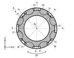
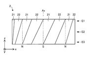
- FIG. 1 is a side view schematically showing the structure of a rotor 2 according to the first embodiment of the present invention.
- the broken line indicates the position of the magnetic pole (N pole or S pole) of the rotor 2.
- FIG. 2 is a plan view schematically showing the structure of the rotor 2.
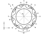
- 3 and 4 are sectional views schematically showing the structure of the rotor 2. 2 is a plan view taken along line C2-C2 in FIG. 1
- FIG. 3 is a sectional view taken along line C3-C3 in FIG.
- FIG. 4 is taken along line C4-C4 in FIG. FIG. 2 to 4, arrows on the rotor 2 indicate main magnetic flux directions.
- the rotor 2 is used for an electric motor (for example, the electric motor 1 described later).
- the rotor 2 has at least one first permanent magnet 21 and at least one second permanent magnet 22 different in type from the first permanent magnet 21.
- the “at least one first permanent magnet 21” includes two or more first permanent magnets 21, and the “at least one second permanent magnet 22” includes two or more second permanent magnets 22.
- the rotor 2 has 2n (n is a natural number) magnetic poles. In this embodiment, n is 4 and the rotor 2 has 8 magnetic poles. In the present embodiment, the rotor 2 has eight first permanent magnets 21 and one second permanent magnet 22. For example, as shown in FIG. 1, the N poles of the first permanent magnets 21 and the S poles of the first permanent magnets 21 are alternately arranged on the outer peripheral surface of the rotor 2. However, the plurality of first permanent magnets 21 may be connected to each other by, for example, a ring-shaped connecting portion, and the second permanent magnets 22 may be divided into a plurality of portions.
- Each of the first permanent magnets 21 forms a part of the outer peripheral surface of the rotor 2.
- Each first permanent magnet 21 is magnetized so as to have polar anisotropy. In other words, each of the first permanent magnets 21 is magnetized so that the rotor 2 has polar anisotropy.
- Each first permanent magnet 21 is a rare earth magnet.
- each first permanent magnet 21 is a bond magnet made by mixing a rare earth magnet and a resin, that is, a rare earth bond magnet.
- Each first permanent magnet 21 has a magnetic force higher than that of the second permanent magnet 22.
- the rare earth magnet is, for example, a magnet containing Nd (neodymium)-Fe (iron)-B (boron) or a magnet containing Sm (samarium)-Fe (iron)-N (nitrogen).
- the resin is, for example, a nylon resin, a PPS (polyphenylene sulfide) resin, or an epoxy resin.
- the second permanent magnet 22 is adjacent to the first permanent magnet 21 in the circumferential direction of the rotor 2 and forms a part of the outer peripheral surface of the rotor 2. Specifically, a part of the second permanent magnet 22 is adjacent to the first permanent magnet 21 in the circumferential direction of the rotor 2, and another part is a first permanent magnet in the radial direction of the rotor 2. It is located inside 21. Therefore, the second permanent magnet 22 is a ring-shaped magnet.
- a plurality of portions of the plurality of first permanent magnets 21 and the plurality of second permanent magnets 22 are alternately arranged in the circumferential direction of the rotor 2. It is arranged.
- the second permanent magnet 22 is magnetized so as to have polar anisotropy.
- the second permanent magnet 22 is magnetized so that the rotor 2 has polar anisotropy.
- the second permanent magnet 22 is one integrated magnet.
- the second permanent magnets 22 form magnetic poles in the rotor 2 together with the respective first permanent magnets 21.
- the second permanent magnet 22 is a magnet different in type from the first permanent magnet 21.
- the second permanent magnet 22 is a ferrite magnet.
- the second permanent magnet 22 is a bond magnet made by mixing a ferrite magnet and a resin, that is, a ferrite bond magnet.
- the resin is, for example, a nylon resin, a PPS (polyphenylene sulfide) resin, or an epoxy resin.
- the second permanent magnet 22 has a magnetic force lower than that of each first permanent magnet.
- each first permanent magnet 21 In the xy plane, the inner peripheral surface and the outer peripheral surface of each first permanent magnet 21 are concentrically formed. That is, the thickness of each first permanent magnet 21 in the xy plane is constant in the circumferential direction.
- FIG. 5 is a diagram showing the length of the first permanent magnet 21 in the axial direction of the rotor 2.
- the length of the first permanent magnet 21 in the axial direction of the rotor 2 is the longest at the center P1 of the first permanent magnet 21 in the circumferential direction of the rotor 2.
- the center P1 of the first permanent magnet 21 in the circumferential direction of the rotor 2 is located on the magnetic pole center of the rotor 2 in the xy plane. That is, as shown in FIG. 5, the length L1 at the center P1 is the longest in each first permanent magnet 21.
- the length of the first permanent magnet 21 in the axial direction of the rotor 2 becomes shorter as it goes away from the center P1 in the circumferential direction.
- the length L2 at the position P2 that is separated from the center P1 in the circumferential direction is shorter than the length L1.
- the length of each first permanent magnet 21 in the axial direction becomes shorter from the magnetic pole center portion (that is, the center P1) toward the interpole portion.
- the inter-pole portion is located at the center of two magnetic poles (that is, N pole and S pole) that are adjacent to each other in the circumferential direction.
- FIG. 6 is a flowchart showing an example of the manufacturing process of the rotor 2.
- 7 and 8 are diagrams showing an example of a forming process of the second permanent magnet 22.
- a magnetizing magnet is used to generate a polar anisotropic magnetic field inside the mold M11 for the second permanent magnet 22.
- the second permanent magnet 22 is molded. Specifically, the second permanent magnet 22 is molded by injection molding in the mold M11 (FIG. 7). As a result, the second permanent magnet 22 magnetized so as to have polar anisotropy is molded. Further, as shown in FIG. 8, the second permanent magnet 22 magnetized so as to have polar anisotropy is obtained by pulling out the mold M11.
- the mold corresponding to the shape of the first permanent magnet 21 is formed in the mold M11, the second permanent magnet 22 is obtained, and at the same time, the shape of the first permanent magnet 21 is formed on the outer peripheral surface of the second permanent magnet 22. Molded.
- a polar anisotropic magnetic field is generated inside the mold for the first permanent magnet 21 using a magnetizing magnet.
- one or more first permanent magnets 21 are molded. Specifically, a part of the outer peripheral surface of the rotor 2 is formed on the outer peripheral surface of the second permanent magnet 22 in a state where the second permanent magnet 22 is arranged inside the mold for the first permanent magnet 21. Thus, one or more first permanent magnets 21 are molded by injection molding. As a result, the one or more first permanent magnets 21 magnetized so as to have polar anisotropy are molded, and the rotor 2 is obtained.
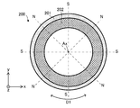
- FIG. 9 is a sectional view schematically showing the structure of the rotor 200 according to the comparative example.
- a ring-shaped rare earth bond magnet 201 having a magnetic force higher than that of the ferrite bond magnet 202 is arranged on the outer peripheral surface of the cylindrical ferrite bond magnet 202.
- the ring-shaped rare earth bonded magnet 201 extends in the circumferential direction of the rotor 200, and the thickness in the xy plane is constant in the axial direction of the rotor 200. That is, the ring-shaped rare earth bonded magnet 201 forms the entire outer peripheral surface of the rotor 200.
- the rotor 2 according to the first embodiment has a plurality of first permanent magnets 21.
- Each first permanent magnet 21 forms a part of the outer peripheral surface of the rotor 2 and does not form the entire outer peripheral surface of the rotor 2.
- the amount of the first permanent magnets 21 having a high magnetic force can be reduced as compared with the rotor 200 according to the comparative example.
- the first permanent magnet 21 is an expensive rare earth bond magnet
- the amount of the rare earth bond magnet can be reduced as compared with the rotor 200 according to the comparative example, and thus the cost of the rotor 2 can be reduced.
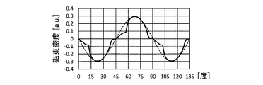
- FIG. 10 is a diagram showing a magnetic flux density distribution on the outer peripheral surface of the rotor 2 corresponding to the vicinity of the cross section of the rotor 2 shown in FIG. Specifically, FIG. 10 is a diagram showing the magnetic flux density distribution at the position E1 shown in FIGS. 14 and 15.
- FIG. 11 is a diagram showing a magnetic flux density distribution on the outer peripheral surface of the rotor 2 corresponding to the vicinity of the cross section of the rotor 2 shown in FIG. Specifically, FIG. 11 is a diagram showing the magnetic flux density distribution at the position E2 shown in FIGS. 14 and 15.
- FIG. 12 is a diagram showing a magnetic flux density distribution on the outer peripheral surface of the rotor 2 corresponding to the vicinity of the cross section of the rotor 2 shown in FIG.
- FIG. 12 is a diagram showing the magnetic flux density distribution at the position E3 shown in FIGS. 14 and 15.
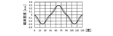
- FIG. 13 is a diagram showing a magnetic flux density distribution on the outer peripheral surface of the entire rotor 2.
- the horizontal axis indicates the relative position [degree] in the circumferential direction of the rotor 2
- the vertical axis indicates the magnetic flux density.
- the solid line shows the magnetic flux density distribution of the rotor 2 according to the first embodiment
- the broken line shows the magnetic flux density distribution of the rotor 200 according to the comparative example.
- FIG. 14 is a diagram showing positions for detecting the magnetic flux density distribution on the outer peripheral surface of the rotor 2 according to the first embodiment.
- the broken line indicates the position of the magnetic pole center portion (N pole or S pole) of the rotor 2, “N” indicates the N pole, and “S” indicates the S pole.
- FIG. 15 is a diagram showing positions for detecting the magnetic flux density distribution on the outer peripheral surface of the rotor 200 according to the comparative example.
- the broken line indicates the position of the magnetic pole center portion (N pole or S pole) of the rotor 200, “N” indicates the N pole, and “S” indicates the S pole.
- a uniform sine wave is formed in the circumferential direction.
- a non-uniform sine wave is formed near each cross section of the rotor 2 according to the first embodiment.
- the magnetic flux density distribution obtained as a whole of the rotor 2 forms a relatively uniform sine wave as shown in FIG. That is, in the entire rotor 2 according to the first embodiment, abrupt changes in magnetic flux density in the circumferential direction are suppressed. Thereby, an induced voltage equivalent to that of the rotor 200 according to the comparative example can be obtained.
- each of the first permanent magnets 21 forms a part of the outer peripheral surface of the rotor 2, so that the first permanent magnets 21 are more permanent than the rotor 200 according to the comparative example. It is possible to reduce the amount of magnets 21 by about 20%.
- the material cost of the rare earth magnet is 10 times or more that of the ferrite magnet.
- the second permanent magnet 22 when a magnet including a rare earth magnet (for example, a rare earth bond magnet) is used as the first permanent magnet 21 and a magnet including a ferrite magnet (for example, a ferrite bond magnet) is used as the second permanent magnet 22, the second permanent magnet is used. Even if the amount of 22 increases, the cost of the first permanent magnet 21 can be significantly reduced. As a result, the cost of the rotor 2 can be significantly reduced.
- a rare earth magnet for example, a rare earth bond magnet
- a magnet including a ferrite magnet for example, a ferrite bond magnet
- a sufficient magnetic force of the rotor 2 can be obtained even if the amount of the first permanent magnets 21 having a high magnetic force is reduced.
- the induced voltage equivalent to that of the rotor 2 according to the comparative example can be obtained, and thus the accuracy of rotation control equivalent to that of the rotor 2 according to the comparative example can be obtained.
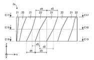
- FIG. 16 is a side view schematically showing the structure of the rotor 2a according to the first modification.
- FIG. 17 is a plan view schematically showing the structure of the rotor 2a according to the first modification.
- 18 and 19 are cross-sectional views schematically showing the structure of the rotor 2a according to the first modification. 17 is a plan view taken along line C17-C17 in FIG. 16
- FIG. 18 is a cross-sectional view taken along line C18-C18 in FIG. 16
- FIG. 19 is taken along line C19-C19 in FIG.
- the width of each first permanent magnet 21 in the circumferential direction of the rotor 2a is different in the axial direction of the rotor 2a.
- the width of the first permanent magnet 21 in the circumferential direction of the rotor 2a is the largest in the center in the axial direction of the rotor 2a. This largest width is indicated by d2 in FIG.
- the width in the circumferential direction is the smallest at the end portion in the axial direction. This smallest width is indicated by d3 in FIG. That is, in each of the first permanent magnets 21, the relationship between the width d2 and the width d3 satisfies d2>d3.
- the width of the outer peripheral surface of the second permanent magnet 22 in the circumferential direction is different in the axial direction. Specifically, the width of the outer peripheral surface of the second permanent magnet 22 in the circumferential direction is the largest at the end portion in the axial direction. This maximum width is indicated by d4 in FIG. The width of the outer peripheral surface of the second permanent magnet 22 in the circumferential direction is the smallest in the middle in the axial direction. This smallest width is indicated by d5 in FIG. That is, in the second permanent magnet 22, the relationship between the width d4 and the width d5 satisfies d4>d5.
- FIG. 20 and FIG. 21 are diagrams showing an example of a manufacturing process of the rotor 2a according to the first modification. Specifically, FIG. 20 and FIG. 21 are diagrams showing a forming process of the second permanent magnet 22.
- the second permanent magnet 22 is molded using a mold divided into two, that is, the mold M21 and the mold M22.
- a polar anisotropy magnetic field is generated inside the mold M21 and the mold M22 for the second permanent magnet 22 using a magnetizing magnet.
- the second permanent magnet 22 is formed. Specifically, in the mold M21 and the mold M22, the second permanent magnet 22 is molded by injection molding (FIG. 20). As a result, the second permanent magnet 22 magnetized so as to have polar anisotropy is molded. Furthermore, as shown in FIG. 21, the second permanent magnet 22 magnetized so as to have polar anisotropy is obtained by pulling out the mold M21 and the mold M22 in opposite directions.
- the mold corresponding to the shape of the first permanent magnet 21 is formed in the mold M21 and the mold M22, the second permanent magnet 22 is obtained, and at the same time, the first permanent magnet is formed on the outer peripheral surface of the second permanent magnet 22. 21 shapes are molded.
- a magnet for magnetizing is used to generate a magnetic field of polar anisotropy inside the mold for the first permanent magnet 21.
- one or more first permanent magnets 21 are formed. Specifically, a part of the outer peripheral surface of the rotor 2a is formed on the outer peripheral surface of the second permanent magnet 22 in a state where the second permanent magnet 22 is arranged inside the mold for the first permanent magnet 21. Thus, one or more first permanent magnets 21 are molded by injection molding. As a result, the one or more first permanent magnets 21 magnetized so as to have polar anisotropy are molded, and the rotor 2 is obtained.
- the other structure of the rotor 2a is the same as that of the rotor 2 according to the first embodiment.
- the rotor 2a according to the first modification has the same effects as the effects of the rotor 2 according to the first embodiment described above.
- the magnetic flux density distribution obtained as the whole rotor 2a can be made into a more uniform sine wave.
- the proportion of harmonic components in the induced voltage can be reduced, and the distortion of the induced voltage is reduced.
- the pulsation of the torque of the electric motor is reduced, and vibration and noise in the electric motor can be reduced.
- the method of manufacturing the rotor 2a according to the first modification it is possible to manufacture the rotor 2a having the above effects. Furthermore, according to the manufacturing method of the rotor 2a, since the divided molds M21 and M22 are used, the degree of freedom in the shape of each first permanent magnet 21 can be increased. Further, according to the manufacturing method of the rotor 2a, the divided molds M21 and M22 are used, so that the mold M21 and the mold M22 can be easily pulled out from the second permanent magnet 22.
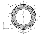
- FIG. 22 is a sectional view schematically showing the structure of the rotor 2b according to Modification 2.
- the angle A1 formed by the rotation center of the rotor 2b that is, the axis Ax
- the two straight lines T11 passing through both ends P11 of the inner peripheral surface of the first permanent magnet 21 is equal to the rotation center of the rotor 2b and the first permanent axis. It is larger than an angle A2 formed by two straight lines T12 passing through both ends P12 of the outer peripheral surface of the magnet 21.
- the inner peripheral surface of the first permanent magnet 21 is a radially inner surface of the first permanent magnet 21.
- the outer peripheral surface of the first permanent magnet 21 is a radially outer surface of the first permanent magnet 21.
- the angle A3 is smaller than the angle A4 on the xy plane. As a result, it is possible to prevent the first permanent magnet 21 from coming off the second permanent magnet 22 due to the centrifugal force generated when the rotor 2b rotates.
- the angle A3 is an angle formed by two straight lines T22 passing through end portions P13 adjacent to each other in the circumferential direction of the rotor 2 on the inner peripheral surfaces of the two first permanent magnets 21 in the xy plane. In other words, the two ends P13 face each other in the circumferential direction of the rotor 2.
- the angle A4 is an angle formed by two straight lines T21 passing through both ends P21 of the outer peripheral surface of the second permanent magnet 22 between the two first permanent magnets 21 in the xy plane.
- the outer peripheral surface of the second permanent magnet 22 is a radially outer surface of the second permanent magnet 22.
- FIG. 23 is a plan view schematically showing the structure of the rotor 2c according to Modification 3.
- FIG. 24 is a side view schematically showing the structure of the rotor 2c according to Modification 3.
- FIG. 25 is a sectional view schematically showing the structure of the rotor 2c according to Modification 3. Specifically, FIG. 25 is a cross-sectional view taken along the line C25-C25 in FIG.
- the first permanent magnet 21 is integrated.
- the first permanent magnet 21 has a plurality of main bodies 21a and at least one ring-shaped portion 21b.
- the plurality of main bodies 21a correspond to the respective first permanent magnets 21 (for example, the respective first permanent magnets 21 shown in FIG. 1) in the first embodiment. Therefore, each main body 21a forms a part of the outer peripheral surface of the rotor 2c and is magnetized so as to have polar anisotropy.
- a part of the second permanent magnet 22 exists between the two main bodies 21a that are adjacent to each other in the circumferential direction.
- the ring-shaped portion 21b is integrated with a plurality of main bodies 21a. Therefore, in Modification 3, the rotor 2c has one first permanent magnet 21 and one second permanent magnet 22.
- the ring-shaped portions 21b are formed at both ends of the first permanent magnet 21 in the axial direction. However, the ring-shaped portion 21b may be formed at one end of the first permanent magnet 21 in the axial direction.
- Each ring-shaped portion 21b covers the end of the second permanent magnet 22 in the axial direction of the rotor 2c.
- each ring-shaped portion 21b may have at least one protrusion 21c or at least one recess 21d.
- Each ring-shaped portion 21b may have both at least one protrusion 21c and at least one recess 21d.
- the protrusion 21c projects toward the second permanent magnet 22.
- the protrusion 21c engages with the recess formed in the second permanent magnet 22.
- the recess 21d engages with a protrusion formed on the second permanent magnet 22.
- the magnet when the temperature of the rotor changes, the magnet may deform. In this case, one of the two types of magnets may come off the rotor due to the difference in heat shrinkage.
- Modification 3 since the rotor 2c has the ring-shaped portion 21b, when the temperature of the rotor 2c changes, even when the first permanent magnet 21 or the second permanent magnet 22 is deformed due to the difference in thermal contraction rate, It is possible to prevent the first permanent magnet 21 (particularly the main body 21a) from coming off the second permanent magnet 22. Furthermore, it is possible to prevent the first permanent magnet 21 (particularly the main body 21a) from coming off the second permanent magnet 22 due to the centrifugal force generated when the rotor 2c rotates.
- each ring-shaped portion 21b has at least one protrusion 21c that engages with the second permanent magnet 22, the first permanent magnet 21 can be firmly fixed to the second permanent magnet 22. As a result, it is possible to effectively prevent the first permanent magnet 21 (particularly the main body 21a) from coming off the second permanent magnet 22.
- each ring-shaped portion 21b has at least one recess 21d that engages with the second permanent magnet 22, the first permanent magnet 21 can be firmly fixed to the second permanent magnet 22. As a result, it is possible to effectively prevent the first permanent magnet 21 (particularly the main body 21a) from coming off the second permanent magnet 22.
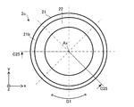
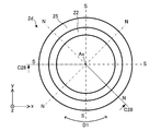
- FIG. 26 is a plan view schematically showing the structure of the rotor 2d according to Modification 4.
- FIG. 27 is a side view schematically showing the structure of the rotor 2d according to Modification 4.
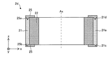
- FIG. 28 is a sectional view schematically showing the structure of a rotor 2d according to Modification 4. Specifically, FIG. 28 is a cross-sectional view taken along the line C28-C28 in FIG.
- the rotor 2d according to Modification 4 further includes at least one resin 25.
- the resin 25 can be integrally formed with ribs for fixing the shaft in the rotor 2d.
- each resin 25 is fixed to both ends of the first permanent magnet 21 in the axial direction of the rotor 2d.
- the resin 25 may be formed on one end of the first permanent magnet 21 in the axial direction of the rotor 2d.
- each resin 25 is a ring-shaped resin in the xy plane.
- Each resin 25 covers the end of the first permanent magnet 21 in the axial direction of the rotor 2d.
- each resin 25 may have at least one protrusion 25a or at least one recess 25b.
- Each resin 25 may have both at least one protrusion 25a and at least one recess 25b.
- the protrusion 25 a projects toward the second permanent magnet 22.
- the protrusion 25a engages with a recess formed in the first permanent magnet 21 or the second permanent magnet 22.
- the recess 25b engages with a protrusion formed on the first permanent magnet 21 or the second permanent magnet 22.
- the magnet when the temperature of the rotor changes, the magnet may deform. In this case, one of the two types of magnets may come off the rotor due to the difference in heat shrinkage.
- Modification 4 since the rotor 2d has the resin 25, even when the first permanent magnet 21 or the second permanent magnet 22 is deformed due to the difference in the thermal contraction rate when the temperature of the rotor 2d is changed, the first It is possible to prevent the permanent magnet 21 from coming off the second permanent magnet 22. Further, it is possible to prevent the first permanent magnet 21 from coming off the second permanent magnet 22 due to the centrifugal force generated when the rotor 2d rotates.
- each resin 25 has at least one protrusion 25a that engages with the first permanent magnet 21 or the second permanent magnet 22, each resin 25 covers each first permanent magnet 21 and 25 can be firmly fixed to the first permanent magnet 21 or the second permanent magnet 22. As a result, it is possible to effectively prevent the first permanent magnet 21 from coming off the second permanent magnet 22.
- each resin 25 has at least one recess 25b that engages with the first permanent magnet 21 or the second permanent magnet 22, each resin 25 covers each first permanent magnet 21, 25 can be firmly fixed to the first permanent magnet 21 or the second permanent magnet 22. As a result, it is possible to effectively prevent the first permanent magnet 21 from coming off the second permanent magnet 22.
- the rotor 2d according to Modification 4 has at least one resin 25, the amount of the first permanent magnets 21 can be reduced compared to the rotor 2c according to Modification 3.
- FIG. 29 is a plan view schematically showing the structure of the rotor 2e according to Modification 5.
- FIG. 30 is a side view schematically showing the structure of the rotor 2e according to Modification 5.
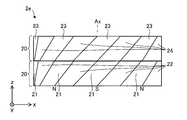
- the rotor 2e according to Modification 5 includes at least one first permanent magnet 21, one second permanent magnet 22, at least one third permanent magnet 23, and at least one fourth permanent magnet 24. ..
- the structure of each third permanent magnet 23 is the same as the structure of the first permanent magnet 21, and the structure of each fourth permanent magnet 24 is the same as the structure of the second permanent magnet 22. is there.
- the third permanent magnet 23 and the fourth permanent magnet 24 are laminated on the first permanent magnet 21 and the second permanent magnet 22 in the axial direction of the rotor 2e.
- each third permanent magnet 23 forms a part of the outer peripheral surface of the rotor 2e, and is magnetized so as to have polar anisotropy.
- Each third permanent magnet 23 is, for example, a bond magnet made by mixing a rare earth magnet and a resin, that is, a rare earth bond magnet.
- Each third permanent magnet 23 has a magnetic force higher than that of the fourth permanent magnet 24.
- the rare earth magnet is, for example, a magnet containing Nd(neodymium)-Fe(iron)-B(boron) or a magnet containing Sm(samarium)-Fe(iron)-N(nitrogen).
- the resin is, for example, a nylon resin, a PPS (polyphenylene sulfide) resin, or an epoxy resin.
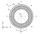
- the fourth permanent magnet 24 is adjacent to the third permanent magnet 23 in the circumferential direction of the rotor 2e and forms a part of the outer peripheral surface of the rotor 2e. Specifically, a part of the fourth permanent magnet 24 is adjacent to the third permanent magnet 23 in the circumferential direction of the rotor 2e, and another part is a third permanent magnet in the radial direction of the rotor 2e. It is located inside 23. Therefore, the fourth permanent magnet 24 is a ring-shaped magnet.
- the fourth permanent magnet 24 is magnetized so as to have polar anisotropy.
- the fourth permanent magnet 24 is a different type of magnet from the third permanent magnet 23.
- the fourth permanent magnet 24 is, for example, a bond magnet made by mixing a ferrite magnet and a resin, that is, a ferrite bond magnet.
- the resin is, for example, a nylon resin, a PPS (polyphenylene sulfide) resin, or an epoxy resin.
- the fourth permanent magnet 24 has a magnetic force lower than that of each third permanent magnet.
- the rotor 2e has two layers of magnets. In other words, the rotor 2e is divided into two layers. That is, the rotor 2e has the first layer magnet 20 composed of the first permanent magnet 21 and the second permanent magnet 22, and the second layer magnet composed of the third permanent magnet 23 and the fourth permanent magnet 24. It has a layer magnet 20. Therefore, since the rotor 2e has a plurality of layers, the eddy current loss in the rotor 2e can be reduced.
- the magnetic pole center position of the first permanent magnet 21 (for example, the N pole position) is preferably coincident with the magnetic pole center position of the third permanent magnet 23 (for example, the N pole position).
- the magnetic flux density at each magnetic pole center position of the rotor 2e can be increased, so that in the electric motor, the magnetic flux flowing from the rotor 2e into the stator is increased, and the output of the electric motor can be increased.
- the magnetic pole center position of the first permanent magnet 21 and the magnetic pole center position of the third permanent magnet 23 are the positions indicated by broken lines in FIG.
- first permanent magnets 21 of the plurality of layer magnets 20 when one cycle is defined as an angle between the N pole and the adjacent N pole in the xy plane, two first permanent magnets 21 that are adjacent to each other in the axial direction are provided.
- the positions of the N poles may be shifted from each other by n/m periods in the circumferential direction with respect to the position at the time of orientation.
- the positions of the S poles of the two first permanent magnets 21 adjacent to each other in the axial direction are also shifted from each other by n/m cycles in the circumferential direction.
- the layer magnets 20 have variations in orientation, variations in magnetic flux density in the circumferential direction are suppressed in the entire rotor 2e, distortion of induced voltage can be reduced, and vibration and vibration in the electric motor can be reduced. Noise can be reduced.
- FIG. 31 is a sectional view schematically showing the structure of a rotor 2f according to Modification 6. Specifically, FIG. 31 is a cross-sectional view taken along the line C31-C31 in FIG. FIG. 32 is a side view schematically showing the structure of the rotor 2f according to Modification 6.
- the rotor 2f according to Modification 6 includes at least one first permanent magnet 21, one second permanent magnet 22, at least one third permanent magnet 23, and at least one fourth permanent magnet 24. ..
- the structure of each third permanent magnet 23 is the same as the structure of the first permanent magnet 21, and the structure of each fourth permanent magnet 24 is the same as the structure of the second permanent magnet 22. is there.
- the third permanent magnet 23 may be integrated or may be divided into a plurality of parts.
- the fourth permanent magnet 24 may be integrated or may be divided into a plurality of parts.
- the third permanent magnet 23 and the fourth permanent magnet 24 are laminated on the first permanent magnet 21 and the second permanent magnet 22 in the axial direction of the rotor 2f.
- each third permanent magnet 23 forms a part of the outer peripheral surface of the rotor 2f, and is magnetized so as to have polar anisotropy.
- Each third permanent magnet 23 is, for example, a bond magnet made by mixing a rare earth magnet and a resin, that is, a rare earth bond magnet.
- Each third permanent magnet 23 has a magnetic force higher than that of the fourth permanent magnet 24.
- the rare earth magnet is, for example, a magnet containing Nd(neodymium)-Fe(iron)-B(boron) or a magnet containing Sm(samarium)-Fe(iron)-N(nitrogen).
- the resin is, for example, a nylon resin, a PPS (polyphenylene sulfide) resin, or an epoxy resin.
- the fourth permanent magnet 24 is adjacent to the third permanent magnet 23 in the circumferential direction of the rotor 2f and forms a part of the outer peripheral surface of the rotor 2f. Specifically, a part of the fourth permanent magnet 24 is adjacent to the third permanent magnet 23 in the circumferential direction of the rotor 2f, and another part is a third permanent magnet in the radial direction of the rotor 2f. It is located inside 23. Therefore, the fourth permanent magnet 24 is a ring-shaped magnet.
- the fourth permanent magnet 24 is magnetized so as to have polar anisotropy.
- the fourth permanent magnet 24 is a different type of magnet from the third permanent magnet 23.
- the fourth permanent magnet 24 is, for example, a bond magnet made by mixing a ferrite magnet and a resin, that is, a ferrite bond magnet.
- the resin is, for example, a nylon resin, a PPS (polyphenylene sulfide) resin, or an epoxy resin.
- the fourth permanent magnet 24 has a magnetic force lower than that of each third permanent magnet.
- the first permanent magnet 21 is integrated.
- the first permanent magnet 21 has a plurality of main bodies 21a and at least one ring-shaped portion 21b (also referred to as a first ring-shaped portion in Modification 6).
- the plurality of main bodies 21a correspond to the respective first permanent magnets 21 (for example, the respective first permanent magnets 21 shown in FIG. 1) in the first embodiment. Therefore, each main body 21a forms a part of the outer peripheral surface of the rotor 2f and is magnetized so as to have polar anisotropy.
- a part of the second permanent magnet 22 exists between the two main bodies 21a that are adjacent to each other in the circumferential direction.
- the ring-shaped portion 21b is integrated with a plurality of main bodies 21a. Therefore, in Modified Example 6, the rotor 2f has one first permanent magnet 21 and one second permanent magnet 22. In the example shown in FIG. 32, the ring-shaped portion 21b is formed at the end of the first permanent magnet 21 in the axial direction. The ring-shaped portion 21b covers the end of the second permanent magnet 22 in the axial direction of the rotor 2f.
- the third permanent magnet 23 is integrated.
- the third permanent magnet 23 has a plurality of main bodies 23a and at least one ring-shaped portion 23b (also referred to as a second ring-shaped portion in Modification 6).
- the plurality of main bodies 23a correspond to each first permanent magnet 21 (for example, each first permanent magnet 21 shown in FIG. 1) in the first embodiment. Therefore, each body 23a forms a part of the outer peripheral surface of the rotor 2f and is magnetized so as to have polar anisotropy.
- a part of the fourth permanent magnet 24 exists between the two main bodies 23a that are adjacent to each other in the circumferential direction.
- the ring-shaped portion 23b is integrated with the plurality of main bodies 23a. Therefore, in Modified Example 6, the rotor 2f has one third permanent magnet 23 and one fourth permanent magnet 24. In the example shown in FIG. 32, the ring-shaped portion 23b is formed at the end of the third permanent magnet 23 in the axial direction. The ring-shaped portion 23b covers the end of the fourth permanent magnet 24 in the axial direction of the rotor 2f.
- the ring-shaped portion 21b faces the ring-shaped portion 23b in the axial direction of the rotor 2f.
- the axial length of the rotor 2f be longer than the axial length of the stator. Thereby, leakage of magnetic flux from the rotor 2f can be reduced. That is, in the electric motor, the magnetic flux flowing from the rotor 2f to the stator increases, and the output of the electric motor can be increased.
- the rotor 2f has two layers of magnets. In other words, the rotor 2f is divided into two layers. That is, the rotor 2f has a first layer composed of the first permanent magnet 21 and the second permanent magnet 22, and a second layer composed of the third permanent magnet 23 and the fourth permanent magnet 24. Therefore, since the rotor 2f has a plurality of layers, the eddy current loss in the rotor 2f can be reduced.
- the magnetic pole center position of the first permanent magnet 21 (for example, the N pole position) is preferably coincident with the magnetic pole center position of the third permanent magnet 23 (for example, the N pole position).
- the magnetic flux density at each magnetic pole center position of the rotor 2f can be increased, so that in the electric motor, the magnetic flux flowing from the rotor 2f into the stator is increased, and the output of the electric motor can be increased.
- the magnetic pole center position of the first permanent magnet 21 and the magnetic pole center position of the third permanent magnet 23 are the positions shown by the broken lines in FIG.
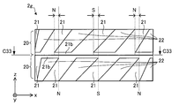
- FIG. 33 is a sectional view schematically showing the structure of a rotor 2g according to Modification 7. 33 is a cross-sectional view taken along the line C33-C33 in FIG.
- FIG. 34 is a side view schematically showing the structure of the rotor 2g according to Modification 7.
- Each layer magnet 20 of the plurality of layer magnets 20 has at least one first permanent magnet 21 and one second permanent magnet 22.
- the plurality of layer magnets 20 are laminated in the axial direction of the rotor 2g.
- the rotor 2g has two layers of magnets. In other words, the rotor 2g is divided into two layers. Therefore, since the rotor 2g has a plurality of layers, eddy current loss in the rotor 2g can be reduced.
- each first permanent magnet 21 faces the ring-shaped portion 21b of the other first permanent magnet 21 in the axial direction of the rotor 2g.
- the ratio of the first permanent magnets 21 can be increased in the central portion of the rotor 2g in the axial direction.
- the electric motor the magnetic flux flowing from the rotor 2g to the stator increases, and the output of the electric motor can be increased.
- each of the first permanent magnets 21 of the plurality of layer magnets 20 when one cycle is defined as an angle between the N pole and the adjacent N pole in the xy plane, two first permanent magnets 21 that are adjacent to each other in the axial direction are provided.
- the positions of the N poles of are shifted from each other by n/m periods in the circumferential direction.
- the positions of the S poles of the two first permanent magnets 21 adjacent to each other in the axial direction are also shifted from each other by n/m cycles in the circumferential direction.
- FIG. 35 is a plan view schematically showing the structure of the rotor 2h according to Modification 8.
- FIG. 36 is a side view schematically showing the structure of the rotor 2h according to Modification 8.
- the structure of the first permanent magnet 21 of the rotor 2h is different from the structure of the first permanent magnet 21 of the rotor 2 according to the first embodiment. Specifically, as shown in FIGS. 35 and 36, both ends of the first permanent magnet 21 in the axial direction overlap with each other by an angle w1 [degree] on the xy plane. In this case, the angle w1 satisfies 0 ⁇ w1 ⁇ 0.2 ⁇ 2n/360. Similar to the first embodiment, the rotor 2h has 2n (n is a natural number) magnetic poles. In the modified example 8, n is 4.
- the volume of the first permanent magnet 21 near the center of the magnetic pole of the rotor 2h can be increased.
- the proportion of the first permanent magnets 21 near the center of the magnetic pole of the rotor 2h can be increased.
- the magnetic force of the rotor 2h can be increased, and the efficiency of the electric motor having the rotor 2h can be improved.
- FIG. 37 is a plan view schematically showing the structure of the rotor 2i according to Modification 9.
- FIG. 38 is a side view schematically showing the structure of the rotor 2i according to Modification 9.
- the structure of the first permanent magnet 21 of the rotor 2i is different from the structure of the first permanent magnet 21 of the rotor 2 according to the first embodiment. Specifically, as shown in FIGS. 37 and 38, both ends of the first permanent magnet 21 in the axial direction overlap with each other by an angle w1 [degree] on the xy plane. In this case, the angle w1 satisfies 0 ⁇ w1 ⁇ 0.2 ⁇ 2n/360. Similar to the first embodiment, the rotor 2i has 2n (n is a natural number) magnetic poles. In the modification 9, n is 4.
- the volume of the first permanent magnet 21 near the center of the magnetic pole of the rotor 2i can be increased.
- the proportion of the first permanent magnets 21 near the center of the magnetic pole of the rotor 2h can be increased.
- the magnetic force of the rotor 2i can be increased, and the efficiency of the electric motor having the rotor 2i can be improved.
- the rotor 2i has a plurality of layer magnets 20 from two layers to m layers (m is a natural number and a divisor of n) stacked in the axial direction.
- m is a natural number and a divisor of n
- Each layer magnet 20 of the plurality of layer magnets 20 has at least one first permanent magnet 21 and one second permanent magnet 22.
- the plurality of layer magnets 20 are laminated in the axial direction of the rotor 2i.
- the rotor 2i has two layers of magnets. In other words, the rotor 2i is divided into two layers. Therefore, since the rotor 2i has a plurality of layers, the eddy current loss in the rotor 2i can be reduced.
- each first permanent magnet 21 faces the ring-shaped part 21b of the other first permanent magnet 21 in the axial direction of the rotor 2i.
- the proportion of the first permanent magnets 21 can be increased in the central portion of the rotor 2i in the axial direction.
- the magnetic flux flowing from the rotor 2i to the stator can be increased.
- each of the first permanent magnets 21 of the plurality of layer magnets 20 when one cycle is defined as an angle between the N pole and the adjacent N pole in the xy plane, two first permanent magnets 21 that are adjacent to each other in the axial direction are provided.
- the positions of the N poles of are shifted from each other by n/m periods in the circumferential direction.
- the positions of the S poles of the two first permanent magnets 21 adjacent to each other in the axial direction are also shifted from each other by n/m cycles in the circumferential direction.
- FIG. 39 is a plan view schematically showing the structure of the rotor 2j according to Modification 10.
- FIG. 40 is a side view schematically showing the structure of the rotor 2j according to Modification 10.
- the structure of the first permanent magnet 21 of the rotor 2j is different from the structure of the first permanent magnet 21 of the rotor 2 according to the first embodiment.
- both ends in the axial direction of the first permanent magnet 21 are overlapped with each other by an angle w2 [degree] in the interpolar portion of the rotor 2j.
- the angle w2 satisfies 0 ⁇ w2 ⁇ 0.2 ⁇ 2n/360.
- the rotor 2i has 2n (n is a natural number) magnetic poles. In the modification 10, n is 4.
- the magnetic flux density distribution obtained as a whole of the rotor 2j can be made into a more uniform sine wave.
- the proportion of harmonic components in the induced voltage can be reduced, and the distortion of the induced voltage is reduced.
- the pulsation of the torque of the electric motor is reduced, and vibration and noise in the electric motor can be reduced.
- the rotor 2j has a plurality of layer magnets 20 from two layers to m layers (m is a natural number and a divisor of n) stacked in the axial direction.
- m is a natural number and a divisor of n
- Each layer magnet 20 of the plurality of layer magnets 20 has at least one first permanent magnet 21 and one second permanent magnet 22.
- the plurality of layer magnets 20 are laminated in the axial direction of the rotor 2j.
- the rotor 2j has two layers of magnets. In other words, the rotor 2j is divided into two layers. Therefore, since the rotor 2j has a plurality of layers, eddy current loss in the rotor 2j can be reduced.
- each of the first permanent magnets 21 of the plurality of layer magnets 20 when one cycle is defined as an angle between the N pole and the adjacent N pole in the xy plane, two first permanent magnets 21 that are adjacent to each other in the axial direction are provided.
- the positions of the N poles of are shifted from each other by n/m periods in the circumferential direction.
- the positions of the S poles of the two first permanent magnets 21 adjacent to each other in the axial direction are also shifted from each other by n/m cycles in the circumferential direction.
- the rotors 2a to 2j according to the modified example described above also have the effects of the rotor 2 according to the first embodiment.
- FIG. 41 is a partial cross-sectional view schematically showing the structure of electric motor 1 according to the second embodiment of the present invention.
- the electric motor 1 has the rotor 2 and the stator 3 according to the first embodiment.
- the rotors 2 a to 2 j according to each modification of the first embodiment can be applied to the electric motor 1.
- the electric motor 1 includes a rotor 2, a stator 3, a circuit board 4, a magnetic sensor 5 for detecting a rotational position of the rotor 2, a bracket 6, bearings 7a and 7b, and a rotational position detection of the rotor 2. It has a sensor magnet 8 as a working magnet and a shaft 37 fixed to the rotor 2.
- the electric motor 1 is, for example, a permanent magnet synchronous electric motor.
- the rotor 2 is rotatably arranged inside the stator 3. An air gap is formed between the rotor 2 and the stator 3. The rotor 2 rotates about the axis Ax.
- the electric motor 1 according to the second embodiment has the rotor 2 (including the modifications) according to the first embodiment, the effects of the rotor 2 described in the first embodiment (including the effects of the modifications) are included. The same effect is obtained.
- the efficiency of the electric motor 1 can be improved.
- FIG. 42 is a diagram schematically showing the structure of the fan 60 according to the third embodiment of the present invention.
- the fan 60 has blades 61 and an electric motor 62.
- the fan 60 is also called a blower.
- the electric motor 62 is the electric motor 1 according to the second embodiment.
- the blade 61 is fixed to the shaft of the electric motor 62.
- the electric motor 62 drives the blade 61.
- the electric motor 62 is driven, the blades 61 rotate and an air flow is generated. As a result, the fan 60 can blow air.
- the fan 60 according to the third embodiment since the electric motor 1 described in the second embodiment is applied to the electric motor 62, the same effect as the effect described in the second embodiment can be obtained. Furthermore, the efficiency of the fan 60 can be improved.
- FIG. 43 is a diagram schematically showing a configuration of the air conditioner 50 according to the fourth embodiment.
- the air conditioner 50 according to Embodiment 4 includes an indoor unit 51 as a blower (first blower), a refrigerant pipe 52, and a blower (second blower) connected to the indoor unit 51 via the refrigerant pipe 52. ) As an outdoor unit 53.
- the indoor unit 51 includes an electric motor 51a (for example, the electric motor 1 according to the second embodiment), a blowing unit 51b that blows air when driven by the electric motor 51a, and a housing 51c that covers the electric motor 51a and the blowing unit 51b. ..
- the blower unit 51b has, for example, blades 51d driven by the electric motor 51a.
- the blades 51d are fixed to the shaft of the electric motor 51a and generate an air flow.
- the outdoor unit 53 has an electric motor 53a (for example, the electric motor 1 according to the second embodiment), a blower unit 53b, a compressor 54, and a heat exchanger (not shown).
- the blower unit 53b blows air by being driven by the electric motor 53a.
- the blower unit 53b has, for example, blades 53d driven by an electric motor 53a.
- the blades 53d are fixed to the shaft of the electric motor 53a and generate an air flow.
- the compressor 54 includes an electric motor 54a (for example, the electric motor 1 according to the second embodiment), a compression mechanism 54b (for example, a refrigerant circuit) driven by the electric motor 54a, and a housing 54c that covers the electric motor 54a and the compression mechanism 54b.
- a compression mechanism 54b for example, a refrigerant circuit
- At least one of the indoor unit 51 and the outdoor unit 53 has the electric motor 1 described in the second embodiment.
- the electric motor 1 described in the second embodiment is applied to at least one of the electric motors 51a and 53a as the drive source of the blower unit. Further, the electric motor 1 described in the second embodiment may be used as the electric motor 54a of the compressor 54.
- the air conditioner 50 can perform an operation such as a cooling operation in which cool air is blown from the indoor unit 51 or a heating operation in which warm air is blown.
- the electric motor 51a is a drive source for driving the blower unit 51b.
- the blower unit 51b can blow the adjusted air.
- the air conditioner 50 of the fourth embodiment since the electric motor 1 described in the second embodiment is applied to at least one of the electric motors 51a and 53a, the same effect as the effect described in the second embodiment can be obtained. Obtainable. Furthermore, the efficiency of the air conditioner 50 can be improved.
- the electric motor 1 according to the second embodiment as a drive source of the blower (for example, the indoor unit 51), the same effect as the effect described in the second embodiment can be obtained. This can improve the efficiency of the blower.
- the blower including the electric motor 1 according to the second embodiment and the blades (for example, the blades 51d or 53d) driven by the electric motor 1 can be used alone as a device for blowing air. This blower can be applied to devices other than the air conditioner 50.
- the electric motor 1 according to the second embodiment as the drive source of the compressor 54, the same effect as the effect described in the second embodiment can be obtained. Furthermore, the efficiency of the compressor 54 can be improved.
- the electric motor 1 described in the second embodiment can be mounted on a device having a drive source such as a ventilation fan, a home electric appliance, or a machine tool, in addition to the air conditioner 50.
- a drive source such as a ventilation fan, a home electric appliance, or a machine tool
Landscapes
- Engineering & Computer Science (AREA)
- Power Engineering (AREA)
- Manufacturing & Machinery (AREA)
- Physics & Mathematics (AREA)
- Electromagnetism (AREA)
- Permanent Field Magnets Of Synchronous Machinery (AREA)
- Iron Core Of Rotating Electric Machines (AREA)
- Connection Of Motors, Electrical Generators, Mechanical Devices, And The Like (AREA)
Abstract
Description
本発明の他の態様に係る回転子は、2n個(nは自然数)の磁極を持ち、軸方向に積層された2層からm層(mは自然数且つnの約数)までの複数の層磁石を備えた回転子であって、前記複数の層磁石の各層磁石は、前記回転子の外周面の一部を形成しており、極異方性を持つように磁化された少なくとも1つの第1永久磁石と、前記少なくとも1つの第1永久磁石とは種類が異なっており、前記回転子の周方向において前記少なくとも1つの第1永久磁石に隣接しており、前記少なくとも1つの第1永久磁石の磁力よりも低い磁力を持ち、極異方性を持つように磁化された少なくとも1つの第2永久磁石とを有し、前記複数の層磁石の各第1永久磁石において、1周期を、前記回転子の軸方向と直交する平面におけるN極と隣り合うN極との間の角度としたとき、前記軸方向において互いに隣接する2つの前記第1永久磁石のN極の位置は、周方向において互いにn/m周期ずれている。
各図に示されるxyz直交座標系において、z軸方向(z軸)は、回転子2の軸線Axと平行な方向を示し、x軸方向(x軸)は、z軸方向(z軸)に直交する方向を示し、y軸方向(y軸)は、z軸方向及びx軸方向の両方に直交する方向を示す。軸線Axは、回転子2の回転中心である。軸線Axは、後述する電動機1の軸線も示す。軸線Axと平行な方向は、「回転子2の軸方向」又は単に「軸方向」ともいう。「径方向」は、回転子2又は固定子3の半径方向であり、軸線Axと直交する方向である。xy平面は、軸方向と直交する平面である。矢印D1は、軸線Axを中心とする周方向を示す。
図2は、回転子2の構造を概略的に示す平面図である。
図3及び図4は、回転子2の構造を概略的に示す断面図である。
図2は、図1における線C2-C2に沿った平面図であり、図3は、図1における線C3-C3に沿った断面図であり、図4は、図1における線C4-C4に沿った断面図である。
図2から図4において、回転子2上の矢印は、主な磁束の向きを示す。
第2永久磁石22は、各第1永久磁石の磁力よりも低い磁力を持つ。
回転子2の軸方向における第1永久磁石21の長さは、回転子2の周方向における第1永久磁石21の中央P1において最も長い。回転子2の周方向における第1永久磁石21の中央P1は、xy平面における回転子2の磁極中心上に位置する。すなわち、図5に示されるように、中央P1における長さL1が、各第1永久磁石21において最も長い。
図6は、回転子2の製造工程の一例を示すフローチャートである。
図7及び図8は、第2永久磁石22の成形工程の一例を示す図である。
図9は、比較例に係る回転子200の構造を概略的に示す断面図である。図9に示される比較例に係る回転子200では、円筒形状のフェライトボンド磁石202の外周面に、フェライトボンド磁石202よりも高い磁力を持つリング形状の希土類ボンド磁石201が配置されている。このリング形状の希土類ボンド磁石201は、回転子200の周方向に延在しており、xy平面における厚みが、回転子200の軸方向において一定である。すなわち、リング形状の希土類ボンド磁石201が、回転子200の外周面の全てを形成している。
図11は、図3に示される回転子2の断面付近に対応する、回転子2の外周面上の磁束密度分布を示す図である。具体的には、図11は、図14及び図15に示される位置E2における磁束密度分布を示す図である。
図12は、図4に示される回転子2の断面付近に対応する、回転子2の外周面上の磁束密度分布を示す図である。具体的には、図12は、図14及び図15に示される位置E3における磁束密度分布を示す図である。
図13は、回転子2全体の外周面上の磁束密度分布を示す図である。
図10から図13において、横軸は、回転子2の周方向における相対位置[度]を示し、縦軸は、磁束密度を示す。図10から図13において、実線は、実施の形態1に係る回転子2の磁束密度分布を示し、破線は、比較例に係る回転子200の磁束密度分布を示す。
図15は、比較例に係る回転子200の外周面上の磁束密度分布を検出する位置を示す図である。図15において、破線は回転子200の磁極中心部(N極又はS極)の位置を示し、「N」はN極を示し、「S」はS極を示す。
図16は、変形例1に係る回転子2aの構造を概略的に示す側面図である。
図17は、変形例1に係る回転子2aの構造を概略的に示す平面図である。
図18及び図19は、変形例1に係る回転子2aの構造を概略的に示す断面図である。
図17は、図16における線C17-C17に沿った平面図であり、図18は、図16における線C18-C18に沿った断面図であり、図19は、図16における線C19-C19に沿った断面図である。
図20及び図21は、変形例1に係る回転子2aの製造工程の一例を示す図である。具体的には、図20及び図21は、第2永久磁石22の成形工程を示す図である。
図22は、変形例2に係る回転子2bの構造を概略的に示す断面図である。
xy平面において、回転子2bの回転中心(すなわち、軸線Ax)と第1永久磁石21の内周面の両端P11を通る2直線T11が成す角度A1は、回転子2bの回転中心と第1永久磁石21の外周面の両端P12を通る2直線T12が成す角度A2よりも大きい。第1永久磁石21の内周面とは、第1永久磁石21の径方向内側の表面である。第1永久磁石21の外周面とは、第1永久磁石21の径方向外側の表面である。
図23は、変形例3に係る回転子2cの構造を概略的に示す平面図である。
図24は、変形例3に係る回転子2cの構造を概略的に示す側面図である。
図25は、変形例3に係る回転子2cの構造を概略的に示す断面図である。具体的には、図25は、図23における線C25-C25に沿った断面図である。
図26は、変形例4に係る回転子2dの構造を概略的に示す平面図である。
図27は、変形例4に係る回転子2dの構造を概略的に示す側面図である。
図28は、変形例4に係る回転子2dの構造を概略的に示す断面図である。具体的には、図28は、図26における線C28-C28に沿った断面図である。
図29は、変形例5に係る回転子2eの構造を概略的に示す平面図である。
図30は、変形例5に係る回転子2eの構造を概略的に示す側面図である。
図31は、変形例6に係る回転子2fの構造を概略的に示す断面図である。具体的には、図31は、図32における線C31-C31に沿った断面図である。
図32は、変形例6に係る回転子2fの構造を概略的に示す側面図である。
図33は、変形例7に係る回転子2gの構造を概略的に示す断面図である。図33は、図34における線C33-C33に沿った断面図である。
図34は、変形例7に係る回転子2gの構造を概略的に示す側面図である。
図35は、変形例8に係る回転子2hの構造を概略的に示す平面図である。
図36は、変形例8に係る回転子2hの構造を概略的に示す側面図である。
図37は、変形例9に係る回転子2iの構造を概略的に示す平面図である。
図38は、変形例9に係る回転子2iの構造を概略的に示す側面図である。
図39は、変形例10に係る回転子2jの構造を概略的に示す平面図である。
図40は、変形例10に係る回転子2jの構造を概略的に示す側面図である。
図41は、本発明の実施の形態2に係る電動機1の構造を概略的に示す部分断面図である。
電動機1は、実施の形態1に係る回転子2と、固定子3とを有する。回転子2の代わりに、実施の形態1の各変形例に係る回転子2aから2jを、電動機1に適用可能である。
図42は、本発明の実施の形態3に係るファン60の構造を概略的に示す図である。
ファン60は、羽根61と、電動機62とを有する。ファン60は、送風機とも言う。電動機62は、実施の形態2に係る電動機1である。羽根61は、電動機62のシャフトに固定されている。電動機62は、羽根61を駆動させる。電動機62が駆動すると、羽根61が回転し、気流が生成される。これにより、ファン60は送風することができる。
本発明の実施の形態4に係る空気調和機50(冷凍空調装置又は冷凍サイクル装置ともいう)について説明する。
図43は、実施の形態4に係る空気調和機50の構成を概略的に示す図である。
Claims (20)
- 2n(nは自然数)個の磁極を持つ回転子であって、
前記回転子の外周面の一部を形成しており、極異方性を持つように磁化された少なくとも1つの第1永久磁石と、
前記少なくとも1つの第1永久磁石とは種類が異なっており、前記回転子の周方向において前記少なくとも1つの第1永久磁石に隣接しており、前記少なくとも1つの第1永久磁石の磁力よりも低い磁力を持ち、極異方性を持つように磁化された少なくとも1つの第2永久磁石と
を備えた
回転子。 - 前記回転子の軸方向における前記少なくとも1つの第1永久磁石の長さは、前記回転子の前記周方向における前記少なくとも1つの第1永久磁石の中央において最も長い請求項1に記載の回転子。
- 前記回転子の軸方向における前記少なくとも1つの第1永久磁石の長さは、前記中央から前記周方向に離れるにつれて短くなる請求項2に記載の回転子。
- 前記回転子の軸方向と直交する平面において、前記回転子の回転中心と前記少なくとも1つの第1永久磁石の内周面の両端を通る2直線が成す角度は、前記回転子の前記回転中心と前記少なくとも1つの第1永久磁石の外周面の両端を通る2直線が成す角度よりも大きい請求項1から3のいずれか1項に記載の回転子。
- 前記少なくとも1つの第1永久磁石は、2つの第1永久磁石を含み、
前記回転子の軸方向と直交する平面において、前記2つの第1永久磁石の内周面の、前記周方向において互いに隣接する端部を通る2直線が成す角度は、前記2つの第1永久磁石の間の前記第2永久磁石の外周面の両端を通る2直線が成す角度よりも小さい請求項1から4のいずれか1項に記載の回転子。 - 前記少なくとも1つの第1永久磁石は、前記回転子の軸方向における前記第2永久磁石の端部を覆うリング状部分を有する請求項1から3のいずれか1項に記載の回転子。
- 前記回転子の軸方向における前記少なくとも1つの第1永久磁石の端部を覆う樹脂をさらに有する請求項1から5のいずれか1項に記載の回転子。
- 前記回転子の外周面の一部を形成しており、極異方性を持つように磁化された少なくとも1つの第3永久磁石と、
前記少なくとも1つの第3永久磁石とは種類が異なっており、前記周方向において前記少なくとも1つの第3永久磁石に隣接しており、前記少なくとも1つの第3永久磁石の磁力よりも低い磁力を持ち、極異方性を持つように磁化された少なくとも1つの第4永久磁石と
をさらに備え、
前記少なくとも1つの第1永久磁石は、前記回転子の軸方向における前記第2永久磁石の端部を覆う第1リング状部分を有し、
前記少なくとも1つの第3永久磁石は、前記回転子の軸方向における前記第4永久磁石の端部を覆う第2リング状部分を有し、
前記回転子の軸方向において、前記第1リング状部分は、前記第2リング状部分に対向している
請求項1から3のいずれか1項に記載の回転子。 - 前記回転子の軸方向と直交する平面において、前記少なくとも1つの第1永久磁石の磁極中心位置は、前記少なくとも1つの第3永久磁石の磁極中心位置と一致している請求項8に記載の回転子。
- 前記回転子の外周面の一部を形成しており、極異方性を持つように磁化された少なくとも1つの第3永久磁石と、
前記少なくとも1つの第3永久磁石とは種類が異なっており、前記周方向において前記少なくとも1つの第3永久磁石に隣接しており、前記少なくとも1つの第3永久磁石の磁力よりも低い磁力を持ち、極異方性を持つように磁化された少なくとも1つの第4永久磁石と
をさらに備え、
前記回転子の軸方向と直交する平面において、前記少なくとも1つの第1永久磁石の磁極中心位置は、前記少なくとも1つの第3永久磁石の磁極中心位置と一致している請求項1から3のいずれか1項に記載の回転子。 - 前記少なくとも1つの第1永久磁石の軸方向における両端は、前記回転子の軸方向と直交する平面において角度w1[度]重なっており、
前記角度w1は、0<w1<0.2×2n/360を満たす
請求項1から3のいずれか1項に記載の回転子。 - 前記回転子の軸方向と直交する平面において、前記少なくとも1つの第1永久磁石の軸方向における両端は、前記回転子の極間部において角度w2[度]重なっており、
前記角度w2は、0<w2<0.2×2n/360を満たす
請求項1又は2に記載の回転子。 - 前記周方向における前記第1永久磁石の幅は、前記回転子の軸方向における真ん中で最も大きい請求項1から3のいずれか1項に記載の回転子。
- 2n個(nは自然数)の磁極を持ち、軸方向に積層された2層からm層(mは自然数且つnの約数)までの複数の層磁石を備えた回転子であって、
前記複数の層磁石の各層磁石は、
前記回転子の外周面の一部を形成しており、極異方性を持つように磁化された少なくとも1つの第1永久磁石と、
前記少なくとも1つの第1永久磁石とは種類が異なっており、前記回転子の周方向において前記少なくとも1つの第1永久磁石に隣接しており、前記少なくとも1つの第1永久磁石の磁力よりも低い磁力を持ち、極異方性を持つように磁化された少なくとも1つの第2永久磁石と
を有し、
前記複数の層磁石の各第1永久磁石において、1周期を、前記回転子の軸方向と直交する平面におけるN極と隣り合うN極との間の角度としたとき、前記軸方向において互いに隣接する2つの前記第1永久磁石のN極の位置は、周方向において互いにn/m周期ずれている
回転子。 - 前記少なくとも1つの第1永久磁石は、希土類磁石である請求項1から14のいずれか1項に記載の回転子。
- 前記第2永久磁石は、フェライト磁石である請求項1から15のいずれか1項に記載の回転子。
- 固定子と、
前記固定子の内側に回転可能に配置された、請求項1から16のいずれか1項に記載の回転子と
を備えた電動機。 - 請求項17に記載の電動機と、
前記電動機によって駆動される羽根と
を備えた送風機。 - 室内機と、
前記室内機に接続された室外機と
を備え、
前記室内機及び前記室外機の少なくとも1つは請求項17に記載の電動機を有する
空気調和機。 - 第1永久磁石と、周方向において前記第1永久磁石に隣接しており、前記第1永久磁石の磁力よりも低い磁力を持つ第2永久磁石とを有する回転子の製造方法であって、
着磁用の磁石を用いて前記第2永久磁石用の金型の内部に極異方性の磁場を発生させる工程と、
極異方性を持つように磁化された前記第2永久磁石を射出成形で成形する工程と、
着磁用の磁石を用いて前記第1永久磁石用の金型の内部に極異方性の磁場を発生させる工程と、
前記第1永久磁石用の金型の内部に前記第2永久磁石を配置した状態で、前記第2永久磁石の外周面に、前記回転子の外周面の一部を形成するように前記第1永久磁石を、射出成形で成形する工程と
を備える
回転子の製造方法。
Priority Applications (6)
| Application Number | Priority Date | Filing Date | Title |
|---|---|---|---|
| EP18943492.1A EP3902114A4 (en) | 2018-12-17 | 2018-12-17 | Rotor, electric motor, fan, air conditioner, and method for manufacturing rotor |
| AU2018453979A AU2018453979B2 (en) | 2018-12-17 | 2018-12-17 | Rotor, electric motor, fan, air conditioner, and method for manufacturing rotor |
| JP2020560654A JP7191121B2 (ja) | 2018-12-17 | 2018-12-17 | 回転子、電動機、送風機、及び空気調和機、並びに回転子の製造方法 |
| CN201880099608.0A CN113169600A (zh) | 2018-12-17 | 2018-12-17 | 转子、电动机、送风机及空气调节机以及转子的制造方法 |
| PCT/JP2018/046344 WO2020129123A1 (ja) | 2018-12-17 | 2018-12-17 | 回転子、電動機、送風機、及び空気調和機、並びに回転子の製造方法 |
| US17/413,353 US11888368B2 (en) | 2018-12-17 | 2018-12-17 | Rotor, electric motor, air blower, air conditioner, and method for fabricating rotor |
Applications Claiming Priority (1)
| Application Number | Priority Date | Filing Date | Title |
|---|---|---|---|
| PCT/JP2018/046344 WO2020129123A1 (ja) | 2018-12-17 | 2018-12-17 | 回転子、電動機、送風機、及び空気調和機、並びに回転子の製造方法 |
Publications (1)
| Publication Number | Publication Date |
|---|---|
| WO2020129123A1 true WO2020129123A1 (ja) | 2020-06-25 |
Family
ID=71102185
Family Applications (1)
| Application Number | Title | Priority Date | Filing Date |
|---|---|---|---|
| PCT/JP2018/046344 Ceased WO2020129123A1 (ja) | 2018-12-17 | 2018-12-17 | 回転子、電動機、送風機、及び空気調和機、並びに回転子の製造方法 |
Country Status (6)
| Country | Link |
|---|---|
| US (1) | US11888368B2 (ja) |
| EP (1) | EP3902114A4 (ja) |
| JP (1) | JP7191121B2 (ja) |
| CN (1) | CN113169600A (ja) |
| AU (1) | AU2018453979B2 (ja) |
| WO (1) | WO2020129123A1 (ja) |
Cited By (5)
| Publication number | Priority date | Publication date | Assignee | Title |
|---|---|---|---|---|
| JPWO2022054149A1 (ja) * | 2020-09-09 | 2022-03-17 | ||
| WO2022153441A1 (ja) * | 2021-01-14 | 2022-07-21 | 三菱電機株式会社 | 回転子、電動機、送風機及び空気調和装置 |
| JPWO2023042366A1 (ja) * | 2021-09-17 | 2023-03-23 | ||
| US20230163648A1 (en) * | 2020-03-27 | 2023-05-25 | Mitsubishi Electric Corporation | Rotor, motor, blower, air conditioner, and manufacturing method of rotor |
| JPWO2023195076A1 (ja) * | 2022-04-05 | 2023-10-12 |
Citations (10)
| Publication number | Priority date | Publication date | Assignee | Title |
|---|---|---|---|---|
| JPS5992759A (ja) * | 1982-11-17 | 1984-05-29 | Toshiba Corp | ブラシレスモ−タ |
| JPH0279738A (ja) * | 1988-09-12 | 1990-03-20 | Mitsubishi Electric Corp | 同期式acサーボモータの回転子 |
| JP2000197288A (ja) * | 1998-12-28 | 2000-07-14 | Kusatsu Denki Kk | モ―タの製造方法 |
| JP2001025193A (ja) * | 1999-07-09 | 2001-01-26 | Nippon Densan Corp | 永久磁石型回転子及び永久磁石飛散防止用カバー |
| JP2003052140A (ja) * | 2001-08-06 | 2003-02-21 | Mitsubishi Electric Corp | Dcブラシレスモータの回転子 |
| JP2005045978A (ja) * | 2003-07-25 | 2005-02-17 | Favess Co Ltd | モータ |
| JP2005151757A (ja) | 2003-11-19 | 2005-06-09 | Mate Co Ltd | ローター及びローターの製造方法 |
| JP2008245488A (ja) * | 2007-03-29 | 2008-10-09 | Tdk Corp | リング状磁石及びその製造方法、並びにモータ |
| JP2010252419A (ja) * | 2009-04-10 | 2010-11-04 | Honda Motor Co Ltd | 電動機、ロータおよび電動機の製造方法 |
| JP2012228072A (ja) * | 2011-04-20 | 2012-11-15 | Mitsubishi Electric Corp | 永久磁石型回転電機およびその製造方法 |
Family Cites Families (13)
| Publication number | Priority date | Publication date | Assignee | Title |
|---|---|---|---|---|
| US5091021A (en) * | 1990-09-28 | 1992-02-25 | General Motors Corporation | Magnetically coded device and method of manufacture |
| US20040108789A1 (en) * | 2002-12-09 | 2004-06-10 | Marshall Eric Giles | High torque brushless DC motors and generators |
| JP2006086319A (ja) * | 2004-09-16 | 2006-03-30 | Mitsubishi Electric Corp | リング型焼結磁石 |
| JP2007208104A (ja) | 2006-02-03 | 2007-08-16 | Matsushita Electric Ind Co Ltd | 複合ボンド磁石成形体 |
| JP5501660B2 (ja) * | 2009-06-04 | 2014-05-28 | カヤバ工業株式会社 | 電動モータ及びそのロータ |
| JP5183608B2 (ja) | 2009-10-14 | 2013-04-17 | 三菱電機株式会社 | 同期電動機の回転子 |
| CN203166649U (zh) | 2012-07-25 | 2013-08-28 | 艾默生环境优化技术(苏州)有限公司 | 混合永磁体转子组件及相应的电机 |
| JP2015122936A (ja) * | 2013-10-31 | 2015-07-02 | 三星電子株式会社Samsung Electronics Co.,Ltd. | 埋込磁石型モータ及び埋込磁石型モータの使用方法 |
| US9780610B2 (en) | 2014-04-14 | 2017-10-03 | Asmo Co., Ltd. | Rotor and motor |
| JP6544992B2 (ja) | 2015-05-21 | 2019-07-17 | 中川電化産業株式会社 | 磁石およびマグネットロータ |
| JP6297222B2 (ja) * | 2015-06-15 | 2018-03-20 | 三菱電機株式会社 | 永久磁石電動機 |
| KR101918065B1 (ko) | 2017-04-06 | 2018-11-13 | 엘지전자 주식회사 | 영구자석을 가지는 전동기 및 이를 구비한 압축기 |
| EP3386075B1 (en) * | 2017-04-06 | 2020-07-29 | LG Electronics Inc. | Electric motor with permament magnet and compressor having the same |
-
2018
- 2018-12-17 EP EP18943492.1A patent/EP3902114A4/en not_active Withdrawn
- 2018-12-17 JP JP2020560654A patent/JP7191121B2/ja active Active
- 2018-12-17 WO PCT/JP2018/046344 patent/WO2020129123A1/ja not_active Ceased
- 2018-12-17 US US17/413,353 patent/US11888368B2/en active Active
- 2018-12-17 CN CN201880099608.0A patent/CN113169600A/zh active Pending
- 2018-12-17 AU AU2018453979A patent/AU2018453979B2/en not_active Ceased
Patent Citations (10)
| Publication number | Priority date | Publication date | Assignee | Title |
|---|---|---|---|---|
| JPS5992759A (ja) * | 1982-11-17 | 1984-05-29 | Toshiba Corp | ブラシレスモ−タ |
| JPH0279738A (ja) * | 1988-09-12 | 1990-03-20 | Mitsubishi Electric Corp | 同期式acサーボモータの回転子 |
| JP2000197288A (ja) * | 1998-12-28 | 2000-07-14 | Kusatsu Denki Kk | モ―タの製造方法 |
| JP2001025193A (ja) * | 1999-07-09 | 2001-01-26 | Nippon Densan Corp | 永久磁石型回転子及び永久磁石飛散防止用カバー |
| JP2003052140A (ja) * | 2001-08-06 | 2003-02-21 | Mitsubishi Electric Corp | Dcブラシレスモータの回転子 |
| JP2005045978A (ja) * | 2003-07-25 | 2005-02-17 | Favess Co Ltd | モータ |
| JP2005151757A (ja) | 2003-11-19 | 2005-06-09 | Mate Co Ltd | ローター及びローターの製造方法 |
| JP2008245488A (ja) * | 2007-03-29 | 2008-10-09 | Tdk Corp | リング状磁石及びその製造方法、並びにモータ |
| JP2010252419A (ja) * | 2009-04-10 | 2010-11-04 | Honda Motor Co Ltd | 電動機、ロータおよび電動機の製造方法 |
| JP2012228072A (ja) * | 2011-04-20 | 2012-11-15 | Mitsubishi Electric Corp | 永久磁石型回転電機およびその製造方法 |
Non-Patent Citations (1)
| Title |
|---|
| See also references of EP3902114A4 |
Cited By (16)
| Publication number | Priority date | Publication date | Assignee | Title |
|---|---|---|---|---|
| US12249871B2 (en) * | 2020-03-27 | 2025-03-11 | Mitsubishi Electric Corporation | Rotor, motor, blower, air conditioner, and manufacturing method of rotor |
| US20230163648A1 (en) * | 2020-03-27 | 2023-05-25 | Mitsubishi Electric Corporation | Rotor, motor, blower, air conditioner, and manufacturing method of rotor |
| JP7415024B2 (ja) | 2020-09-09 | 2024-01-16 | 三菱電機株式会社 | 電動機、送風機及び空気調和装置 |
| WO2022054149A1 (ja) * | 2020-09-09 | 2022-03-17 | 三菱電機株式会社 | 回転子、電動機、送風機及び空気調和装置 |
| JPWO2022054149A1 (ja) * | 2020-09-09 | 2022-03-17 | ||
| CN116034529A (zh) * | 2020-09-09 | 2023-04-28 | 三菱电机株式会社 | 转子、电动机、送风机以及空调装置 |
| AU2020467017B2 (en) * | 2020-09-09 | 2024-02-01 | Mitsubishi Electric Corporation | Rotor, motor, blower, and air conditioner |
| EP4213346A4 (en) * | 2020-09-09 | 2023-11-01 | Mitsubishi Electric Corporation | Rotor, electric motor, blower, and air conditioning device |
| WO2022153441A1 (ja) * | 2021-01-14 | 2022-07-21 | 三菱電機株式会社 | 回転子、電動機、送風機及び空気調和装置 |
| JPWO2022153441A1 (ja) * | 2021-01-14 | 2022-07-21 | ||
| JP7442688B2 (ja) | 2021-01-14 | 2024-03-04 | 三菱電機株式会社 | 回転子、電動機、送風機及び空気調和装置 |
| JPWO2023042366A1 (ja) * | 2021-09-17 | 2023-03-23 | ||
| WO2023042366A1 (ja) * | 2021-09-17 | 2023-03-23 | 三菱電機株式会社 | 回転子、電動機、送風機、空気調和装置、及び回転子の製造方法 |
| WO2023195076A1 (ja) * | 2022-04-05 | 2023-10-12 | 三菱電機株式会社 | 電動機、送風機および空気調和装置 |
| JPWO2023195076A1 (ja) * | 2022-04-05 | 2023-10-12 | ||
| JP7706645B2 (ja) | 2022-04-05 | 2025-07-11 | 三菱電機株式会社 | 電動機、送風機および空気調和装置 |
Also Published As
| Publication number | Publication date |
|---|---|
| JPWO2020129123A1 (ja) | 2021-06-10 |
| EP3902114A4 (en) | 2021-12-29 |
| AU2018453979B2 (en) | 2022-12-22 |
| JP7191121B2 (ja) | 2022-12-16 |
| US11888368B2 (en) | 2024-01-30 |
| AU2018453979A1 (en) | 2021-06-17 |
| US20220045589A1 (en) | 2022-02-10 |
| EP3902114A1 (en) | 2021-10-27 |
| CN113169600A (zh) | 2021-07-23 |
Similar Documents
| Publication | Publication Date | Title |
|---|---|---|
| JP7072726B2 (ja) | 回転子、電動機、送風機、空気調和機、及び回転子の製造方法 | |
| JP7191121B2 (ja) | 回転子、電動機、送風機、及び空気調和機、並びに回転子の製造方法 | |
| JP5816822B2 (ja) | モータおよびそれを搭載した電気機器 | |
| JPWO2019049203A1 (ja) | コンシクエントポール型ロータ、電動機、圧縮機、送風機、及び空気調和機 | |
| JP6615375B2 (ja) | 電動機および空気調和装置 | |
| CN116134707A (zh) | 电动机 | |
| JPWO2020090007A1 (ja) | 回転子、コンシクエントポール型回転子、電動機、送風機、冷凍空調装置、回転子の製造方法、及びコンシクエントポール型回転子の製造方法 | |
| JP2023060060A (ja) | ロータ、電動機、ファン、及び空気調和機 | |
| CN102904358B (zh) | 永久磁体转子和组装该永久磁体转子的方法 | |
| JP7098047B2 (ja) | モータ、ファン、および空気調和機 | |
| CN116349116B (zh) | 电动机、风扇以及空调机 | |
| JP7026805B2 (ja) | ステータ、モータ、ファン、及び空気調和機並びにステータの製造方法 | |
| JP7058740B2 (ja) | モータ、ファン、空気調和装置、及びモータの製造方法 | |
| WO2021171476A1 (ja) | 電動機、ファン、及び空気調和機 | |
| WO2021171474A1 (ja) | コンシクエントポール型ロータ、電動機、ファン、及び空気調和機 | |
| JP7531692B2 (ja) | 回転子、電動機、送風機及び空気調和装置 | |
| JPWO2020026403A1 (ja) | ロータ、モータ、ファン、空気調和装置、及びロータの製造方法 | |
| WO2024100869A1 (ja) | 回転子、電動機、ファン、及び空気調和機 | |
| CN118591965A (zh) | 转子、电动机、送风机以及空调装置 |
Legal Events
| Date | Code | Title | Description |
|---|---|---|---|
| 121 | Ep: the epo has been informed by wipo that ep was designated in this application |
Ref document number: 18943492 Country of ref document: EP Kind code of ref document: A1 |
|
| ENP | Entry into the national phase |
Ref document number: 2020560654 Country of ref document: JP Kind code of ref document: A |
|
| ENP | Entry into the national phase |
Ref document number: 2018453979 Country of ref document: AU Date of ref document: 20181217 Kind code of ref document: A |
|
| NENP | Non-entry into the national phase |
Ref country code: DE |
|
| ENP | Entry into the national phase |
Ref document number: 2018943492 Country of ref document: EP Effective date: 20210719 |